Embed Size (px)
Citation preview
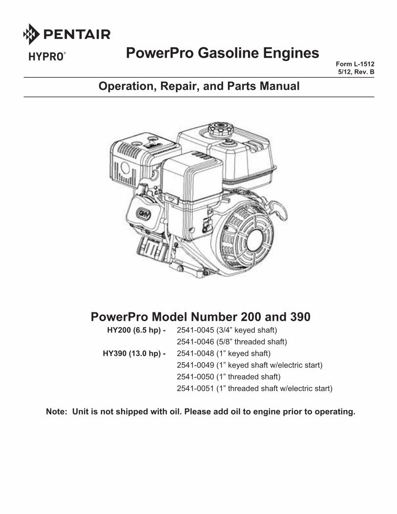
PowerPro Gasoline Engines
Operation, Repair, and Parts Manual
Form L-1512 5/12, Rev. B
PowerPro Model Number 200 and 390 HY200 (6.5 hp) - 2541-0045 (3/4” keyed shaft) 2541-0046 (5/8” threaded shaft) HY390 (13.0 hp) - 2541-0048 (1” keyed shaft) 2541-0049 (1” keyed shaft w/electric start) 2541-0050 (1” threaded shaft) 2541-0051 (1” threaded shaft w/electric start)
Note: Unit is not shipped with oil. Please add oil to engine prior to operating.
ENGINE SAFETY ..................................................................................................................................... 3COMPONENTS & CONTROL LOCATIONS ............................................................................................ 4CONTROLS .............................................................................................................................................. 5CHECK BEFORE OPERATION ............................................................................................................... 6OPERATION ............................................................................................................................................ 7MAINTENANCE ....................................................................................................................................... 9STORAGE/TRANSPORTATION ............................................................................................................ 16TROUBLESHOOTING ........................................................................................................................... 18TECHNICAL & CONSUMER INFORMATION ........................................................................................ 19SPECIFICATIONS .................................................................................................................................. 22ENGINE REPLACEMENT PARTS ......................................................................................................... 23WIRING DIAGRAMS .............................................................................................................................. 24OPTIONAL PARTS – BATTERY ............................................................................................................ 26EMISSIONS WARRANTY ...................................................................................................................... 27
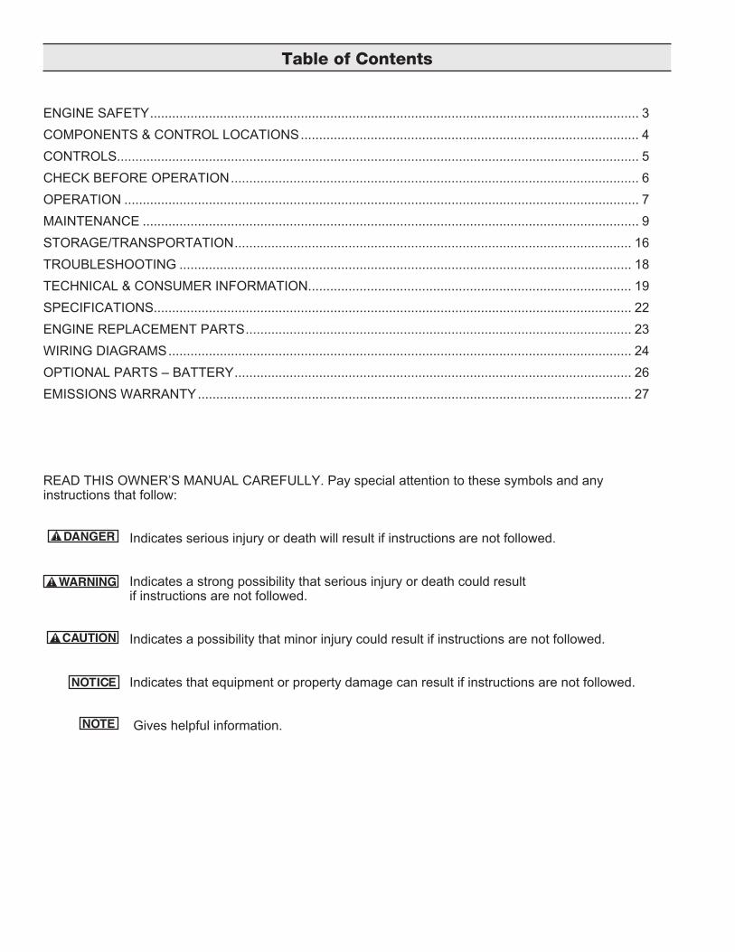
READ THIS OWNER’S MANUAL CAREFULLY. Pay special attention to these symbols and any instructions that follow:
Indicates serious injury or death will result if instructions are not followed.
Indicates a strong possibility that serious injury or death could result if instructions are not followed.
Indicates a possibility that minor injury could result if instructions are not followed. Indicates that equipment or property damage can result if instructions are not followed.
Gives helpful information.
Table of Contents
3
California Proposition 65 Warning -- This product and related accessories contain chemicals known to the State of California to cause cancer, birth defects or other reproductive harm.
IMPORTANT SAFETY INFORMATIONMost accidents with engines can be prevented if you follow all instructions in this manual and on the engine. Some of the most common hazards are discussed below, along with the best way to protect yourself and others.
Owner Responsibilities• The engines are designed to give safe and dependable service if operated according to instructions. Read and understand this owner’s manual before operating the engine. Failure to do so could result in personal injury or equipment damage.• Know how to stop the engine quickly, and under-stand the operation of all controls. Never permit anyone to operate the engine without proper instructions.• Do not allow children to operate the engine. Keep children and pets away from the area of operation.
Refuel with CareGasoline is extremely flammable, and gasoline vapor can explode. Refuel outdoors, in a well-ven-tilated area, with the engine stopped. Never smoke near gasoline, and keep other flames and sparks away. Always store gasoline in an approved con-tainer. If any fuel is spilled, make sure the area is dry before starting the engine.
Hot Exhaust• The muffler becomes very hot during operation and remains hot for a while after stopping the en-gine. Be careful not to touch the muffler while it is hot. Let the engine cool before storing it indoors.• To prevent fire hazards and to provide adequate ventilation for stationary equipment applications, keep the engine at least 3 feet (1 meter) away from building walls and other equipment during opera-tion. Do not place flammable objects close to the engine.
Carbon Monoxide HazardExhaust gas contains poisonous carbon monox-ide. Avoid inhalation of exhaust gas. Never run the engine in a closed garage or confined area.
Other EquipmentReview the instructions provided with the equip-ment powered by this engine for any additional safety precautions that should be observed in con-junction with engine startup, shutdown, operation, or protective apparel that may be needed to oper-ate the equipment.
Engine Safety Information
4
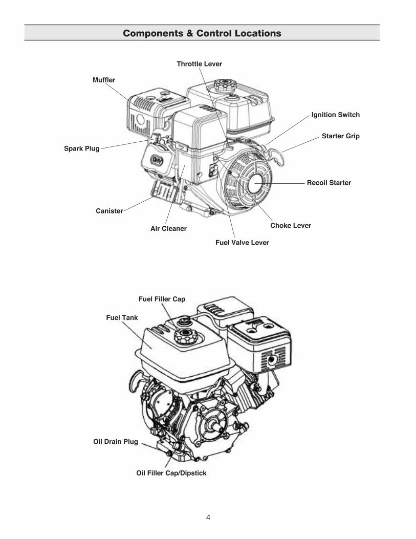
Components & Control Locations
Fuel Filler Cap
Ignition Switch
Starter Grip
Recoil Starter
Muffler
Throttle Lever
Spark Plug
Canister
Air Cleaner Choke Lever
Fuel Valve Lever
Fuel Tank
Oil Drain Plug
Oil Filler Cap/Dipstick
5
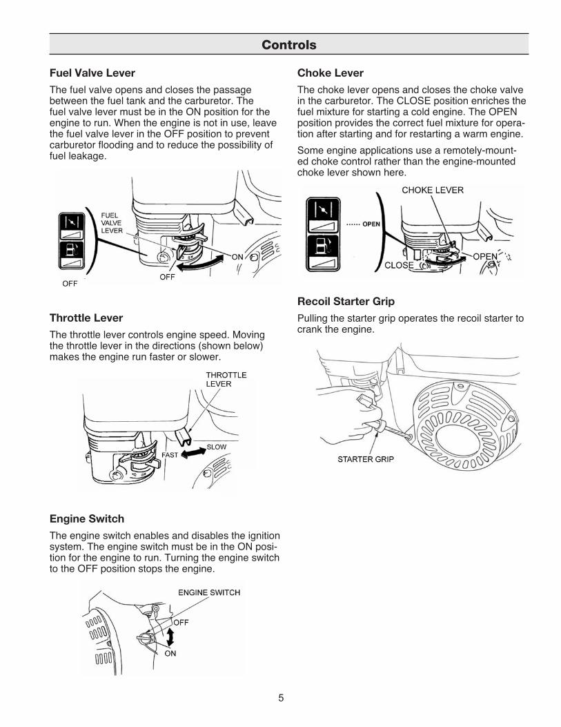
Fuel Valve LeverThe fuel valve opens and closes the passage between the fuel tank and the carburetor. The fuel valve lever must be in the ON position for the engine to run. When the engine is not in use, leave the fuel valve lever in the OFF position to prevent carburetor flooding and to reduce the possibility of fuel leakage.
Throttle LeverThe throttle lever controls engine speed. Moving the throttle lever in the directions (shown below) makes the engine run faster or slower.
Engine SwitchThe engine switch enables and disables the ignition system. The engine switch must be in the ON posi-tion for the engine to run. Turning the engine switch to the OFF position stops the engine.
Choke LeverThe choke lever opens and closes the choke valve in the carburetor. The CLOSE position enriches the fuel mixture for starting a cold engine. The OPEN position provides the correct fuel mixture for opera-tion after starting and for restarting a warm engine.Some engine applications use a remotely-mount-ed choke control rather than the engine-mounted choke lever shown here.
Recoil Starter GripPulling the starter grip operates the recoil starter to crank the engine.
Controls
6
IS YOUR ENGINE READY TO GO? For your safety, and to maximize the service life of your equipment, it is very important to take a few moments before you operate the engine to check its condition. Be sure to take care of any problem you find, or have your servicing dealer correct it, prior to operating the engine.
Improperly maintaining this engine, or failing to correct a problem before operation, could cause a malfunction in which you could be seriously injured.Always perform a preoperation inspection before each operation, and correct any problem.
Before beginning your preoperation checks, be sure the engine is level and the engine switch is in the OFF position.
Check the General Condition of the Engine • Look around and underneath the engine for signs of oil or gasoline leaks. • Remove any excessive dirt or debris, especially around the muffler and recoil starter. • Look for signs of damage. • Check that all shields and covers are in place, and all nuts, bolts, and screws are tightened.
Check the Engine • Check the engine oil level. Running the engine with a low oil level can cause engine damage. The Low Oil Sensor (applicable engine types) will automatically stop the engine before the oil level falls below safe limits. However, to avoid the inconvenience of an unexpected shutdown, always check the engine oil level before startup. • Check the air filter. A dirty air filter will restrict air flow to the carburetor, reducing engine performance. • Check the fuel level. Starting with a full tank will help to eliminate or reduce operating interruptions for refueling.
Check the Equipment Powered by this Engine Review the instructions provided with the equipment powered by this engine for any precautions and procedures that should be followed before engine startup.
Check Before Operation
7
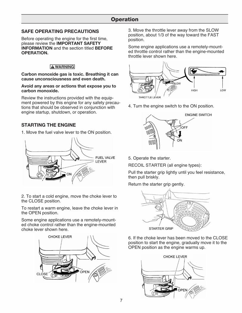
SAFE OPERATING PRECAUTIONS Before operating the engine for the first time, please review the IMPORTANT SAFETY INFORMATION and the section titled BEFORE OPERATION.
Carbon monoxide gas is toxic. Breathing it can cause unconsciousness and even death.Avoid any areas or actions that expose you to carbon monoxide.Review the instructions provided with the equip-ment powered by this engine for any safety precau-tions that should be observed in conjunction with engine startup, shutdown, or operation.
STARTING THE ENGINE 1. Move the fuel valve lever to the ON position.
2. To start a cold engine, move the choke lever to the CLOSE position. To restart a warm engine, leave the choke lever in the OPEN position. Some engine applications use a remotely-mount-ed choke control rather than the engine-mounted choke lever shown here.
3. Move the throttle lever away from the SLOW position, about 1/3 of the way toward the FAST position. Some engine applications use a remotely-mount-ed throttle control rather than the engine-mounted throttle lever shown here.
4. Turn the engine switch to the ON position.
5. Operate the starter. RECOIL STARTER (all engine types): Pull the starter grip lightly until you feel resistance, then pull briskly. Return the starter grip gently.
6. If the choke lever has been moved to the CLOSE position to start the engine, gradually move it to the OPEN position as the engine warms up.
Operation

8
SETTING ENGINE SPEED Position the throttle lever for the desired engine speed. Some engine applications use a remote-ly-mounted throttle control rather than the engine-mounted throttle lever shown here. For engine speed recommendations, refer to the instructions provided with the equipment powered by this engine.
STOPPING THE ENGINE To stop the engine in an emergency, simply turn the engine switch to the OFF position. Under nor-mal conditions, use the following procedure. 1. Move the throttle lever to the SLOW position. Some engine applications use a remotely-mount-ed throttle control rather than the engine-mounted throttle lever shown here.
2. Turn the engine switch to the OFF position.
3. Turn the fuel valve lever to the OFF position.
Operation

9
THE IMPORTANCE OF MAINTENANCE Good maintenance is essential for safe, econom-ical, and trouble-free operation. It will also help reduce air pollution.
Improperly maintaining this engine, or failure to correct a problem before operation, can cause a malfunction in which you can be seriously hurt or killed. Always follow the inspection and maintenance recommendations and schedules in this own-er’s manual.
To help you properly care for your engine, the following pages include a maintenance schedule, routine inspection procedures, and simple main-tenance procedures using basic hand tools. Other service tasks that are more difficult, or require spe-cial tools, are best handled by professionals and are normally performed by a technician or other qualified mechanic. The maintenance schedule applies to normal oper-ating conditions. If you operate your engine under unusual conditions, such as sustained high-load or high-temperature operation, or use in unusually wet or dusty conditions, consult your servicing dealer for recommendations applicable to your individual needs and use.
MAINTENANCE SAFETY Some of the most important safety precautions are as follows. (Note: We cannot warn you of every conceivable hazard that can arise in performing maintenance. Only you can decide whether or not you should perform a given task.)
Failure to properly follow maintenance instructions and precautions can cause you to be seriously hurt or killed. Always follow the procedures and precautions in the owner’s manual.
Safety Precautions • Make sure the engine is off before you begin any maintenance or repairs. This will eliminate several potential hazards:
• Carbon monoxide poisoning from engine exhaust. Be sure there is adequate ventilation whenever you operate the engine. • Burns from hot parts. Let the engine and exhaust system cool before touching. • Injury from moving parts. Do not run the engine unless instructed to do so.
• Read the instructions before you begin, and make sure you have the tools and skills required to per-form the maintenance. • To reduce the possibility of fire or explosion, be careful when working around gasoline. Use only a nonflammable solvent, not gasoline, to clean parts. Keep cigarettes, sparks and flames away from all fuel-related parts. Remember that your servicing dealer knows your engine best and is fully equipped to maintain and repair it.To ensure the best quality and reliability, use only new, genuine parts or their equivalents for repair and replacement.
Maintenance
10
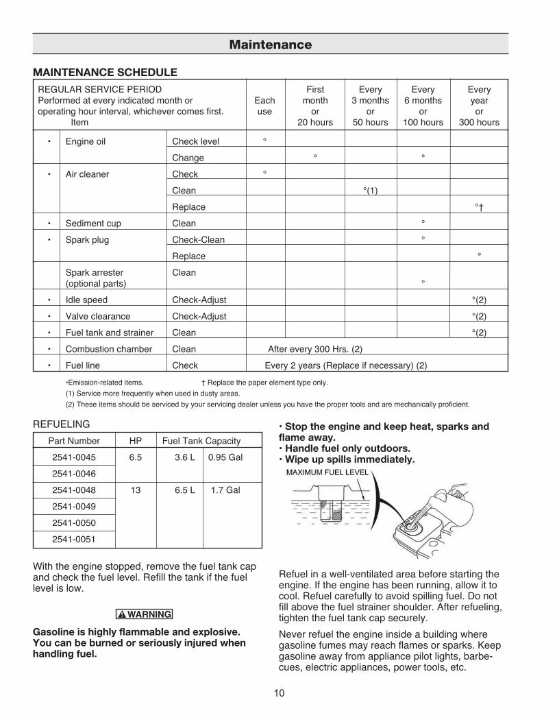
REFUELING Part Number HP Fuel Tank Capacity
2541-0045 6.5 3.6 L 0.95 Gal
2541-0046
2541-0048 13 6.5 L 1.7 Gal
2541-0049
2541-0050
2541-0051
With the engine stopped, remove the fuel tank cap and check the fuel level. Refill the tank if the fuel level is low.
Gasoline is highly flammable and explosive. You can be burned or seriously injured when handling fuel.
• Stop the engine and keep heat, sparks and flame away. • Handle fuel only outdoors. • Wipe up spills immediately.
Refuel in a well-ventilated area before starting the engine. If the engine has been running, allow it to cool. Refuel carefully to avoid spilling fuel. Do not fill above the fuel strainer shoulder. After refueling, tighten the fuel tank cap securely. Never refuel the engine inside a building where gasoline fumes may reach flames or sparks. Keep gasoline away from appliance pilot lights, barbe-cues, electric appliances, power tools, etc.
Maintenance
MAINTENANCE SCHEDULE REGULAR SERVICE PERIOD First Every Every Every Performed at every indicated month or Each month 3 months 6 months year operating hour interval, whichever comes first. use or or or or Item 20 hours 50 hours 100 hours 300 hours
• Engine oil Check level °
Change ° °
• Air cleaner Check °
Clean °(1)
Replace °†
• Sediment cup Clean °
• Spark plug Check-Clean °
Replace °
Spark arrester Clean (optional parts) °
• Idle speed Check-Adjust °(2)
• Valve clearance Check-Adjust °(2)
• Fuel tank and strainer Clean °(2)
• Combustion chamber Clean After every 300 Hrs. (2)
• Fuel line Check Every 2 years (Replace if necessary) (2)
•Emission-related items. † Replace the paper element type only. (1) Service more frequently when used in dusty areas. (2) These items should be serviced by your servicing dealer unless you have the proper tools and are mechanically proficient.
11
Spilled fuel is not only a fire hazard, it causes envi-ronmental damage. Wipe up spills immediately.
Fuel can damage paint and plastic. Be care-ful not to spill fuel when filling your fuel tank. Damage caused by spilled fuel is not covered under warranty.
FUEL RECOMMENDATIONS Use unleaded gasoline with a pump octane rating of 86 or higher. These engines are certified to operate on unlead-ed gasoline. Unleaded gasoline produces fewer engine and spark plug deposits and extends exhaust system life. Never use stale or contaminated gasoline or an oil/gasoline mixture. Avoid getting dirt or water in the fuel tank. Occasionally you may hear a light ‘‘spark knock’’ or ‘‘pinging’’ (metallic rapping noise) while operating under heavy loads. This is no cause for concern. If spark knock or pinging occurs at a steady engine speed, under normal load, change brands of gas-oline. If spark knock or pinging persists, see an authorized servicing dealer. Running the engine with persistent spark knock or pinging can cause engine damage. Running the engine with persistent spark knock or pinging is considered misuse, and Hypro’s Limited Warranty does not cover parts dam-aged by misuse.
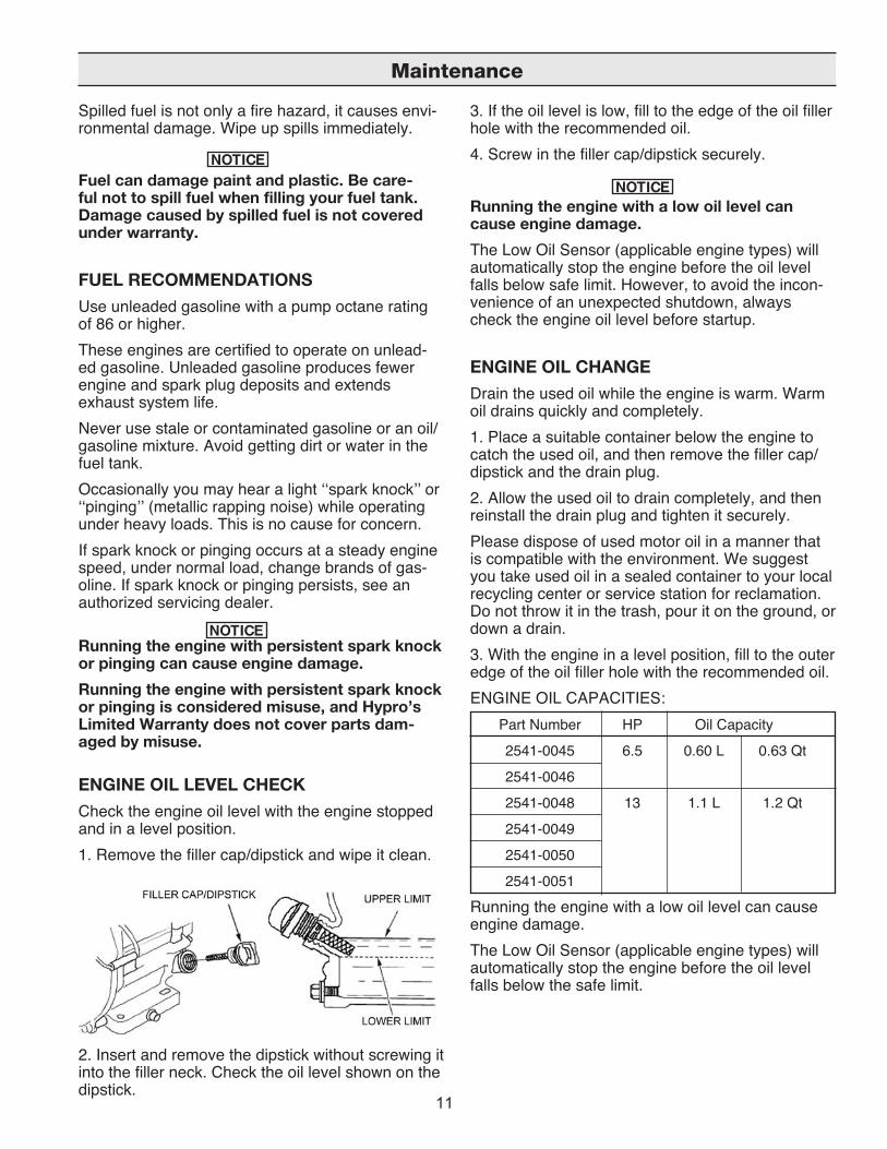
ENGINE OIL LEVEL CHECK Check the engine oil level with the engine stopped and in a level position. 1. Remove the filler cap/dipstick and wipe it clean.
2. Insert and remove the dipstick without screwing it into the filler neck. Check the oil level shown on the dipstick.
3. If the oil level is low, fill to the edge of the oil filler hole with the recommended oil. 4. Screw in the filler cap/dipstick securely.
Running the engine with a low oil level can cause engine damage. The Low Oil Sensor (applicable engine types) will automatically stop the engine before the oil level falls below safe limit. However, to avoid the incon-venience of an unexpected shutdown, always check the engine oil level before startup.
ENGINE OIL CHANGE Drain the used oil while the engine is warm. Warm oil drains quickly and completely. 1. Place a suitable container below the engine to catch the used oil, and then remove the filler cap/dipstick and the drain plug. 2. Allow the used oil to drain completely, and then reinstall the drain plug and tighten it securely. Please dispose of used motor oil in a manner that is compatible with the environment. We suggest you take used oil in a sealed container to your local recycling center or service station for reclamation. Do not throw it in the trash, pour it on the ground, or down a drain. 3. With the engine in a level position, fill to the outer edge of the oil filler hole with the recommended oil. ENGINE OIL CAPACITIES: Part Number HP Oil Capacity
2541-0045 6.5 0.60 L 0.63 Qt
2541-0046
2541-0048 13 1.1 L 1.2 Qt
2541-0049
2541-0050
2541-0051
Running the engine with a low oil level can cause engine damage. The Low Oil Sensor (applicable engine types) will automatically stop the engine before the oil level falls below the safe limit.
Maintenance
12
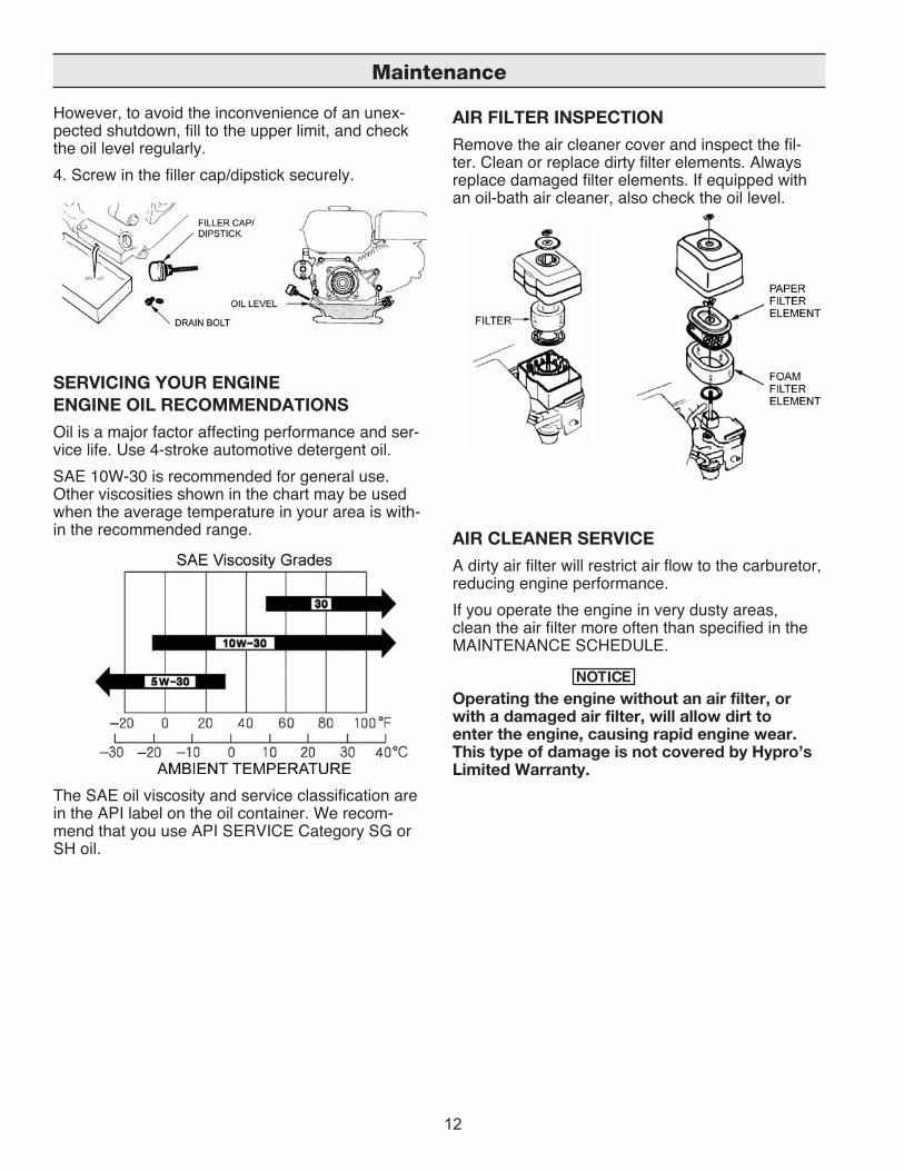
However, to avoid the inconvenience of an unex-pected shutdown, fill to the upper limit, and check the oil level regularly. 4. Screw in the filler cap/dipstick securely.
SERVICING YOUR ENGINEENGINE OIL RECOMMENDATIONS Oil is a major factor affecting performance and ser-vice life. Use 4-stroke automotive detergent oil. SAE 10W-30 is recommended for general use. Other viscosities shown in the chart may be used when the average temperature in your area is with-in the recommended range.
The SAE oil viscosity and service classification are in the API label on the oil container. We recom-mend that you use API SERVICE Category SG or SH oil.
AIR FILTER INSPECTION Remove the air cleaner cover and inspect the fil-ter. Clean or replace dirty filter elements. Always replace damaged filter elements. If equipped with an oil-bath air cleaner, also check the oil level.
AIR CLEANER SERVICEA dirty air filter will restrict air flow to the carburetor, reducing engine performance. If you operate the engine in very dusty areas, clean the air filter more often than specified in the MAINTENANCE SCHEDULE.
Operating the engine without an air filter, or with a damaged air filter, will allow dirt to enter the engine, causing rapid engine wear. This type of damage is not covered by Hypro’s Limited Warranty.
Maintenance
13
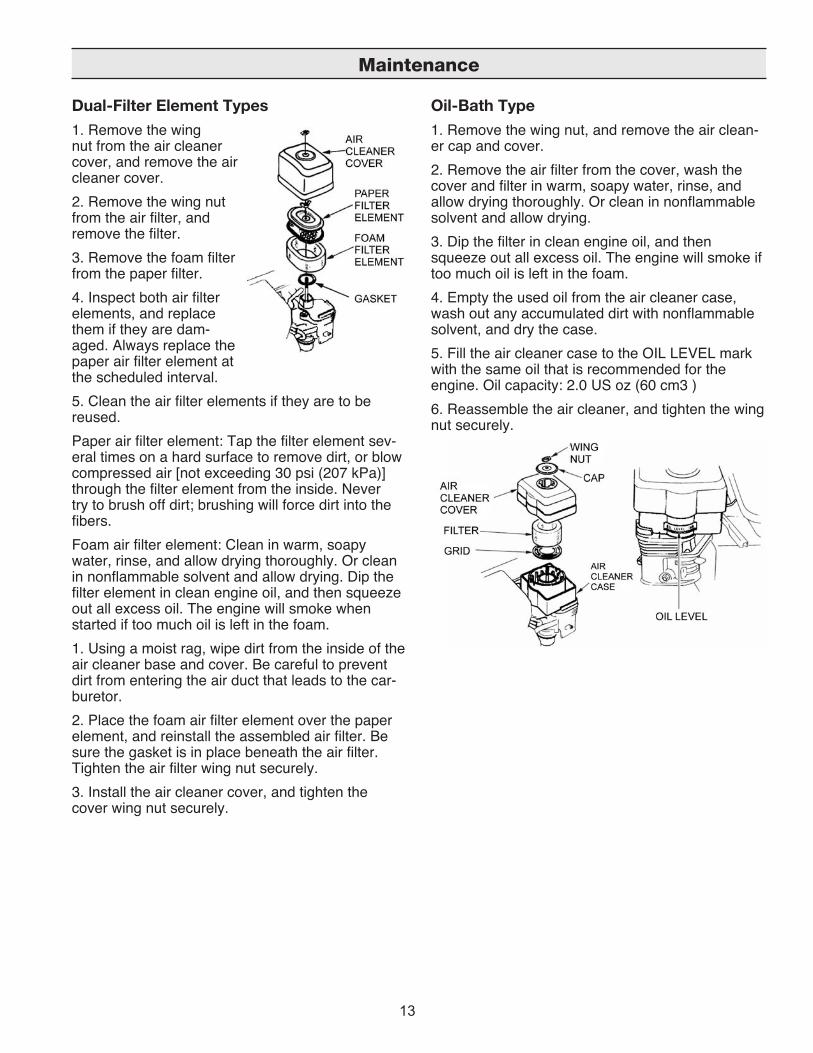
Dual-Filter Element Types 1. Remove the wing nut from the air cleaner cover, and remove the air cleaner cover. 2. Remove the wing nut from the air filter, and remove the filter. 3. Remove the foam filter from the paper filter. 4. Inspect both air filter elements, and replace them if they are dam-aged. Always replace the paper air filter element at the scheduled interval.5. Clean the air filter elements if they are to be reused. Paper air filter element: Tap the filter element sev-eral times on a hard surface to remove dirt, or blow compressed air [not exceeding 30 psi (207 kPa)] through the filter element from the inside. Never try to brush off dirt; brushing will force dirt into the fibers. Foam air filter element: Clean in warm, soapy water, rinse, and allow drying thoroughly. Or clean in nonflammable solvent and allow drying. Dip the filter element in clean engine oil, and then squeeze out all excess oil. The engine will smoke when started if too much oil is left in the foam. 1. Using a moist rag, wipe dirt from the inside of the air cleaner base and cover. Be careful to prevent dirt from entering the air duct that leads to the car-buretor. 2. Place the foam air filter element over the paper element, and reinstall the assembled air filter. Be sure the gasket is in place beneath the air filter. Tighten the air filter wing nut securely. 3. Install the air cleaner cover, and tighten the cover wing nut securely.
Oil-Bath Type1. Remove the wing nut, and remove the air clean-er cap and cover. 2. Remove the air filter from the cover, wash the cover and filter in warm, soapy water, rinse, and allow drying thoroughly. Or clean in nonflammable solvent and allow drying. 3. Dip the filter in clean engine oil, and then squeeze out all excess oil. The engine will smoke if too much oil is left in the foam. 4. Empty the used oil from the air cleaner case, wash out any accumulated dirt with nonflammable solvent, and dry the case. 5. Fill the air cleaner case to the OIL LEVEL mark with the same oil that is recommended for the engine. Oil capacity: 2.0 US oz (60 cm3 ) 6. Reassemble the air cleaner, and tighten the wing nut securely.
Maintenance
14
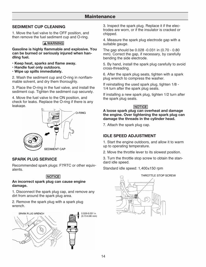
SEDIMENT CUP CLEANING 1. Move the fuel valve to the OFF position, and then remove the fuel sediment cup and O-ring.
Gasoline is highly flammable and explosive. You can be burned or seriously injured when han-dling fuel. • Keep heat, sparks and flame away. • Handle fuel only outdoors. • Wipe up spills immediately.2. Wash the sediment cup and O-ring in nonflam-mable solvent, and dry them thoroughly. 3. Place the O-ring in the fuel valve, and install the sediment cup. Tighten the sediment cup securely. 4. Move the fuel valve to the ON position, and check for leaks. Replace the O-ring if there is any leakage.
SPARK PLUG SERVICERecommended spark plugs: F7RTC or other equiv-alents.
An incorrect spark plug can cause engine damage. 1. Disconnect the spark plug cap, and remove any dirt from around the spark plug area.2. Remove the spark plug with a spark plug wrench.
3. Inspect the spark plug. Replace it if the elec-trodes are worn, or if the insulator is cracked or chipped. 4. Measure the spark plug electrode gap with a suitable gauge. The gap should be 0.028 -0.031 in (0.70 - 0.80 mm). Correct the gap, if necessary, by carefully bending the side electrode. 5. By hand, install the spark plug carefully to avoid cross-threading. 6. After the spark plug seats, tighten with a spark plug wrench to compress the washer. If reinstalling the used spark plug, tighten 1/8 - 1/4 turn after the spark plug seats. If installing a new spark plug, tighten 1/2 turn after the spark plug seats.
A loose spark plug can overheat and damage the engine. Over tightening the spark plug can damage the threads in the cylinder head. 7. Attach the spark plug cap.
IDLE SPEED ADJUSTMENT1. Start the engine outdoors, and allow it to warm up to operating temperature.2. Move the throttle lever to its slowest position. 3. Turn the throttle stop screw to obtain the stan-dard idle speed. Standard idle speed: 1,400±150 rpm
Maintenance
15
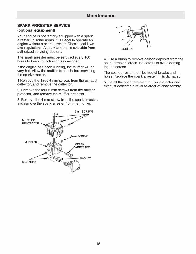
SPARK ARRESTER SERVICE (optional equipment) Your engine is not factory-equipped with a spark arrester. In some areas, it is illegal to operate an engine without a spark arrester. Check local laws and regulations. A spark arrester is available from authorized servicing dealers. The spark arrester must be serviced every 100 hours to keep it functioning as designed. If the engine has been running, the muffler will be very hot. Allow the muffler to cool before servicing the spark arrester. 1 Remove the three 4 mm screws from the exhaust deflector, and remove the deflector. 2. Remove the four 5 mm screws from the muffler protector, and remove the muffler protector. 3. Remove the 4 mm screw from the spark arrester, and remove the spark arrester from the muffler.
4. Use a brush to remove carbon deposits from the spark arrester screen. Be careful to avoid damag-ing the screen. The spark arrester must be free of breaks and holes. Replace the spark arrester if it is damaged.5. Install the spark arrester, muffler protector and exhaust deflector in reverse order of disassembly.
Maintenance

16
STORING YOUR ENGINE Storage Preparation Proper storage preparation is essential for keeping your engine trouble free and looking good. The following steps will help to keep rust and corrosion from impairing your engine’s function and appear-ance, and will make the engine easier to start after storage.
Cleaning If the engine has been running, allow it to cool for at least half an hour before cleaning. Clean all exterior surfaces, touch up any damaged paint, and coat other areas that may rust with a light film of oil.
Using a garden hose or pressure washing equipment can force water into the air clean-er or muffler opening. Water in the air cleaner will soak the air filter, and water that passes through the air filter or muffler can enter the cylinder, causing damage.Water contacting a hot engine can cause dam-age. If the engine has been running, allow it to cool for at least half an hour before washing.
Fuel Gasoline will oxidize and deteriorate in storage. Old gasoline will cause hard starting, and it leaves gum deposits that clog the fuel system. If the gasoline in your engine deteriorates during storage, you may need to have the carburetor and other fuel system components serviced or replaced. The length of time that gasoline can be left in your fuel tank and carburetor without causing functional problems will vary with such factors as gasoline blend, your storage temperatures, and whether the fuel tank is partially or completely filled. The air in a partially-filled fuel tank promotes fuel deteriora-tion. Very warm storage temperatures accelerate fuel deterioration. Fuel deterioration problems may occur within a few months, or even less if the gaso-line was not fresh when you filled the fuel tank.
Hypro’s Limited Warranty does not cover fuel system damage or engine performance prob-lems resulting from neglected storage prepara-tion.
You can extend fuel storage life by adding a fuel stabilizer that is formulated for that purpose, or you can avoid fuel deterioration problems by draining the fuel tank and carburetor.
Adding a Fuel Stabilizer to Extend Fuel Storage Life When adding a fuel stabilizer, fill the fuel tank with fresh gasoline. If only partially filled, air in the tank will promote fuel deterioration during storage. If you keep a container of gasoline for refueling, be sure that it contains only fresh gasoline. 1. Add fuel stabilizer following the manufacturer’s instructions. 2. After adding a fuel stabilizer, run the engine outdoors for 10 minutes to be sure that treated gasoline has replaced the untreated gasoline in the carburetor. 3. Stop the engine, and move the fuel valve to the OFF position.
Draining the Fuel Tank and Carburetor1. Place an approved gasoline container below the carburetor, and use a funnel to avoid spilling fuel. 2. Remove the carburetor drain bolt and sediment cup, and then move the fuel valve lever to the ON position.
3. After all the fuel has drained into the container, reinstall the drain bolt and sediment cup. Tighten them securely.
Storage/Transportation
17
Storage Precautions1. Change the engine oil. 2. Remove the spark plugs. 3. Pour a tablespoon (5-10 cc) of clean engine oil into the cylinder. 4. Pull the starter rope several times to distribute the oil in the cylinder. 5. Reinstall the spark plugs.6. Pull the starter rope slowly until resistance is felt. This will close the valves so moisture cannot enter the engine cylinder. Return the starter rope gently. If your engine will be stored with gasoline in the fuel tank and carburetor, it is important to reduce the hazard of gasoline vapor ignition. Select a well-ven-tilated storage area away from any appliance that operates with a flame, such as a furnace, water heater or clothes dryer. Also avoid any area with a spark-producing electric motor, or where power tools are operated. If possible, avoid storage areas with high humidity, because that promotes rust and corrosion. Unless all fuel has been drained from the fuel tank, leave the fuel valve lever in the OFF position to reduce the possibility of fuel leakage. Position the equipment so the engine is level. Tilting can cause fuel or oil leakage. With the engine and exhaust system cool, cover the engine to keep out dust. A hot engine and exhaust system can ignite or melt some materials. Do not use sheet plastic as a dust cover. A nonporous cover will trap moisture around the engine, promot-ing rust and corrosion. If equipped with a battery for an electric starter, recharge the battery once a month while the engine is in storage. This will help to extend the service life of the battery.
Removal from Storage Check your engine as described in the section CHECK BEFORE OPERATION. If the fuel was drained during storage prepara-tion, fill the tank with fresh gasoline. If you keep a container of gasoline for refueling, be sure that it contains only fresh gasoline. Gasoline oxidizes and deteriorates over time, causing hard starting. If the cylinders were coated with oil during storage preparation, the engine may smoke briefly at start-up. This is normal.
TRANSPORTING If the engine has been running, allow it to cool for at least 15 minutes before loading the engine-pow-ered equipment on the transport vehicle. A hot engine and exhaust system can burn you and can ignite some materials. Keep the engine level when transporting to reduce the possibility of fuel leakage. Move the fuel valve lever to the OFF position.
Storage/Transportation

18
ENGINE WILL NOT START Possible Cause Correction
1. Electric starting: Battery discharged. Recharge battery. check battery.
2. Check control positions. Fuel valve OFF. Move lever to ON.
Choke OPEN. Move lever to CLOSE unless engine is warm.
Engine switch OFF. Turn engine switch to ON.
3. Check fuel. Out of fuel. Refuel.
Bad fuel; engine stored without Drain fuel tank and carburetor. treating or draining gasoline, or Refuel with fresh gasoline. refueled with bad gasoline.
4. Remove and inspect Spark plugs faulty, fouled, or Gap, or replace spark plugs. spark plugs. improperly gapped.
Spark plugs wet with fuel Dry and reinstall spark plugs. (flooded engine). Start engine with throttle lever in FAST position.
5. Other conditions. Fuel filter clogged, carburetor Replace or repair faulty malfunction, ignition malfunction, components as necessary. valve stuck, etc.
ENGINE LACKS POWER Possible Cause Correction
1. Check air filter. Filter element(s) clogged. Clean or replace filter element(s).
2. Check fuel. Out of fuel. Refuel.
Bad fuel; engine stored without Drain fuel tank and carburetor. treating or draining gasoline, or Refuel with fresh gasoline. refueled with bad gasoline.
3. Other conditions. Fuel filter clogged, carburetor Replace or repair faulty malfunction, ignition malfunction, components as necessary. valve stuck, etc.
Troubleshooting
19
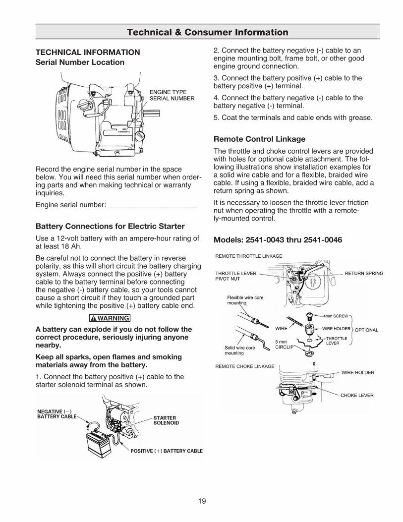
TECHNICAL INFORMATION Serial Number Location
Record the engine serial number in the space below. You will need this serial number when order-ing parts and when making technical or warranty inquiries. Engine serial number: ______________________
Battery Connections for Electric Starter Use a 12-volt battery with an ampere-hour rating of at least 18 Ah. Be careful not to connect the battery in reverse polarity, as this will short circuit the battery charging system. Always connect the positive (+) battery cable to the battery terminal before connecting the negative (-) battery cable, so your tools cannot cause a short circuit if they touch a grounded part while tightening the positive (+) battery cable end.
A battery can explode if you do not follow the correct procedure, seriously injuring anyone nearby. Keep all sparks, open flames and smoking materials away from the battery. 1. Connect the battery positive (+) cable to the starter solenoid terminal as shown.
2. Connect the battery negative (-) cable to an engine mounting bolt, frame bolt, or other good engine ground connection. 3. Connect the battery positive (+) cable to the battery positive (+) terminal. 4. Connect the battery negative (-) cable to the battery negative (-) terminal. 5. Coat the terminals and cable ends with grease.
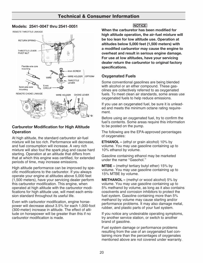
Remote Control Linkage The throttle and choke control levers are provided with holes for optional cable attachment. The fol-lowing illustrations show installation examples for a solid wire cable and for a flexible, braided wire cable. If using a flexible, braided wire cable, add a return spring as shown. It is necessary to loosen the throttle lever friction nut when operating the throttle with a remote-ly-mounted control.
Models: 2541-0043 thru 2541-0046
Technical & Consumer Information
20
Models: 2541-0047 thru 2541-0051
Carburetor Modification for High Altitude Operation At high altitude, the standard carburetor air-fuel mixture will be too rich. Performance will decrease, and fuel consumption will increase. A very rich mixture will also foul the spark plug and cause hard starting. Operation at an altitude that differs from that at which this engine was certified, for extended periods of time, may increase emissions. High altitude performance can be improved by spe-cific modifications to the carburetor. If you always operate your engine at altitudes above 5,000 feet (1,500 meters), have your servicing dealer perform this carburetor modification. This engine, when operated at high altitude with the carburetor modi-fications for high altitude use, will meet each emis-sion standard throughout its useful life. Even with carburetor modification, engine horse-power will decrease about 3.5% for each 1,000-foot (300-meter) increase in altitude. The effect of alti-tude on horsepower will be greater than this if no carburetor modification is made.
When the carburetor has been modified for high altitude operation, the air-fuel mixture will be too lean for low altitude use. Operation at altitudes below 5,000 feet (1,500 meters) with a modified carburetor may cause the engine to overheat and result in serious engine damage. For use at low altitudes, have your servicing dealer return the carburetor to original factory specifications.
Oxygenated Fuels Some conventional gasolines are being blended with alcohol or an ether compound. These gas-olines are collectively referred to as oxygenated fuels. To meet clean air standards, some areas use oxygenated fuels to help reduce emissions. If you use an oxygenated fuel, be sure it is unlead-ed and meets the minimum octane rating require-ment. Before using an oxygenated fuel, try to confirm the fuel’s contents. Some areas require this information to be posted on the pump. The following are the EPA-approved percentages of oxygenates: ETHANOL – (ethyl or grain alcohol) 10% by volume. You may use gasoline containing up to 10% ethanol by volume. Gasoline containing ethanol may be marketed under the name ‘‘Gasohol.’’MTBE – (methyl tertiary butyl ether) 15% by volume. You may use gasoline containing up to 15% MTBE by volume. METHANOL – (methyl or wood alcohol) 5% by volume. You may use gasoline containing up to 5% methanol by volume, as long as it also contains cosolvents and corrosion inhibitors to protect the fuel system. Gasoline containing more than 5% methanol by volume may cause starting and/or performance problems. It may also damage metal, rubber, and plastic parts of your fuel system. If you notice any undesirable operating symptoms, try another service station, or switch to another brand of gasoline. Fuel system damage or performance problems resulting from the use of an oxygenated fuel con-taining more than the percentages of oxygenates mentioned above are not covered under warranty.
Technical & Consumer Information
21
EMISSION CONTROL SYSTEM INFORMATION Source of EmissionsThe combustion process produces carbon monoxide, oxides of nitrogen, and hydrocarbons. Control of hydrocarbons and oxides of nitrogen is very important because, under certain conditions, they react to form photochemical smog when subjected to sunlight. Carbon monoxide does not react in the same way, but it is toxic. This utilizes lean carburetor settings and other systems to reduce the emissions of carbon monoxide, oxides of nitrogen and hydrocarbons.
Tampering and Altering Tampering with or altering the emission control system may increase emissions beyond the legal limit. Among those acts that constitute tampering are: • Removal or alteration of any part of the intake, fuel or exhaust systems. • Altering or defeating the governor linkage or speed-adjusting mechanism to cause the engine to operate outside its design parameters.
Problems that may Affect Emissions If you are aware of any of the following symptoms, have your engine inspected and repaired by your servicing dealer. • Hard starting or stalling after starting • Rough idle • Misfiring or backfiring under load • Afterburning (backfiring) • Black exhaust smoke or high fuel consumption
Replacement Parts The emission control systems on your engine were designed, built. We recommend the use of genuine parts whenever you have maintenance done. These original-design replacement parts are manufactured to the same standards as the original parts, so you can be confident of their performance. The use of replacement parts that are not of the original design and quality may impair the effectiveness of your emission control system. A manufacturer of an aftermarket part assumes the responsibility that the part will not adversely affect emission performance. The manufacturer or rebuilder of the part must certify that use of the part will not result in a failure of the engine to comply with emission regulations.
Maintenance Follow the maintenance schedule. Remember that this schedule is based on the assumption that your machine will be used for its designed purpose. Sustained high-load or high-temperature operation, or use in unusually wet or dusty conditions, will require more frequent service.
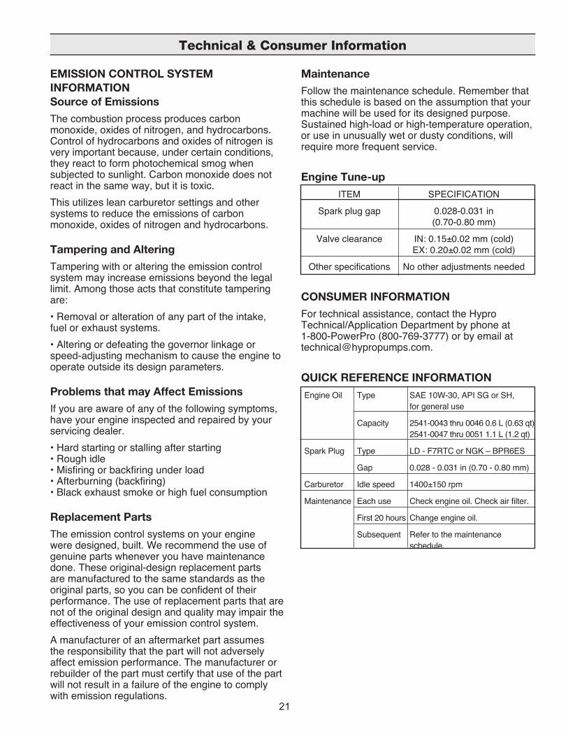
Engine Tune-up ITEM SPECIFICATION
Spark plug gap 0.028-0.031 in (0.70-0.80 mm)
Valve clearance IN: 0.15±0.02 mm (cold) EX: 0.20±0.02 mm (cold)
Other specifications No other adjustments needed
CONSUMER INFORMATION For technical assistance, contact the Hypro Technical/Application Department by phone at 1-800-PowerPro (800-769-3777) or by email at [email protected].
QUICK REFERENCE INFORMATION Engine Oil Type SAE 10W-30, API SG or SH, for general use
Capacity 2541-0043 thru 0046 0.6 L (0.63 qt) 2541-0047 thru 0051 1.1 L (1.2 qt)
Spark Plug Type LD - F7RTC or NGK – BPR6ES
Gap 0.028 - 0.031 in (0.70 - 0.80 mm)
Carburetor Idle speed 1400±150 rpm
Maintenance Each use Check engine oil. Check air filter.
First 20 hours Change engine oil.
Subsequent Refer to the maintenance schedule.
Technical & Consumer Information
22
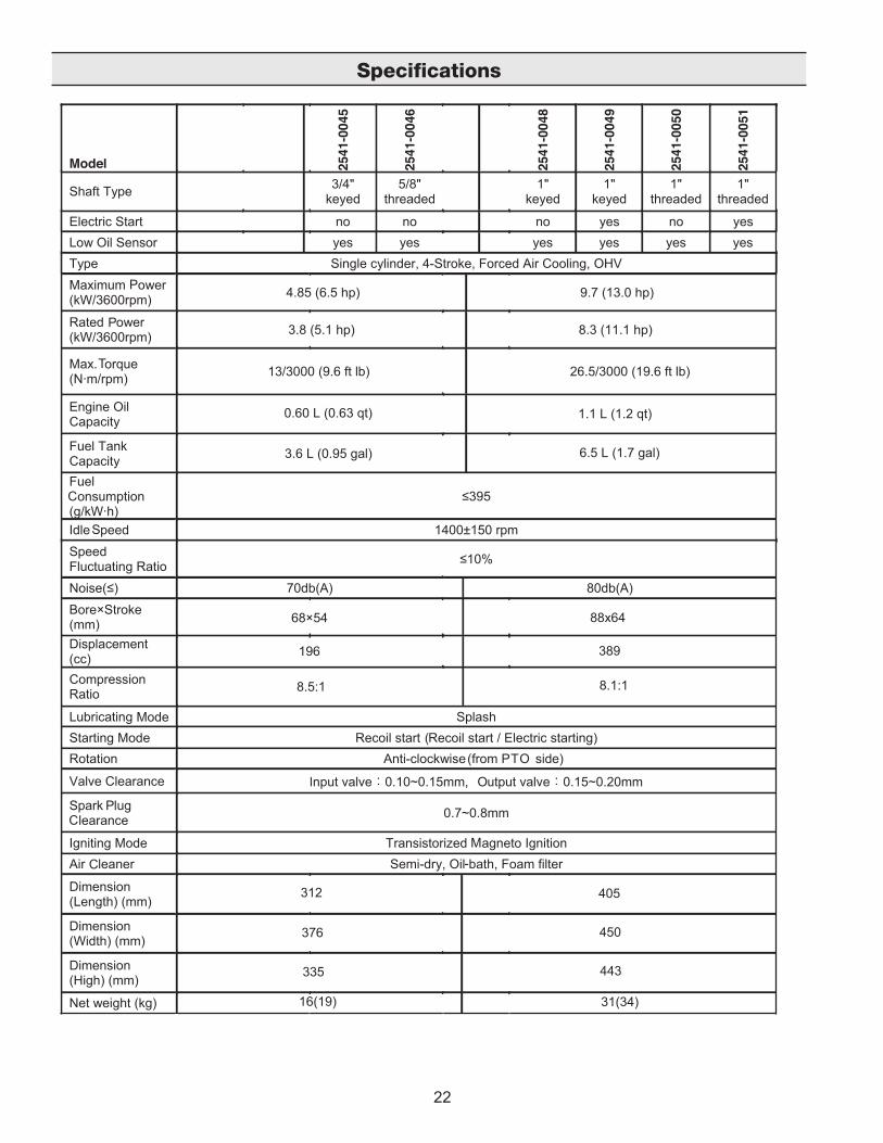
Specifications
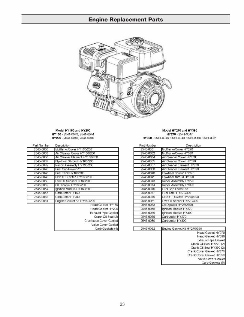
23
Engine Replacement Parts
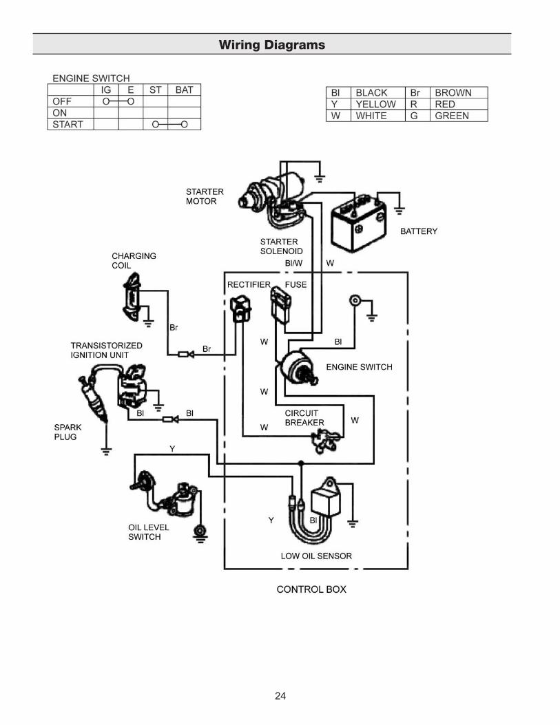
24
Wiring Diagrams

25
Wiring Diagrams
Engine Type with Oil Alert and without Electric Starting
26
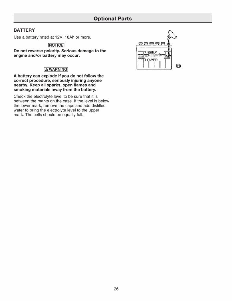
BATTERYUse a battery rated at 12V, 18Ah or more.
Do not reverse polarity. Serious damage to the engine and/or battery may occur.
A battery can explode if you do not follow the correct procedure, seriously injuring anyone nearby. Keep all sparks, open flames and smoking materials away from the battery.Check the electrolyte level to be sure that it is between the marks on the case. If the level is below the lower mark, remove the caps and add distilled water to bring the electrolyte level to the upper mark. The cells should be equally full.
Optional Parts
27
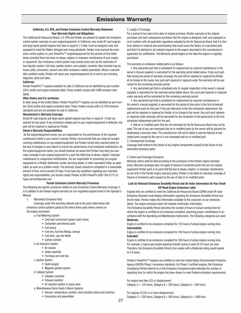
Emissions Warranty
Limited Warranty on PowerPro Gasoline EnginesHypro warrants to the original purchaser of its PowerPro gasoline engine to be free from defects in material and workmanship under normal use for the period of one (1) year from the date of purchase. This warranty does not cover freight damage, normal wear and tear, or damage caused by misapplication, lack of routine maintenance, negligence, alterations, or repair that affects the performance or reliability of the engine (see limitations and exclusions listed below). The repair or replacement of any part or parts under this Limited Warranty shall not extend the terms of the warranty beyond the original warrantable period.
THIS WARRANTY IS EXCLUSIVE. HYPRO MAKES NO OTHER WARRANTY, EXPRESS OR IMPLIED, INCLUDING BUT NOT LIMITED TO ANY WARRANTY OF MERCHANTABILITY OR FITNESS FOR A PARTICULAR PURPOSE.
Hypro’s obligation under this warranty is, at Hypro’s option, to either repair or replace free of charge, any part, or parts of the engine upon return of the entire product to the Hypro factory in accordance with the return procedures set forth below. THIS IS THE EXCLUSIVE REMEDY FOR ANY BREACH OF WARRANTY.
LIMITATIONS AND EXCLUSIONS: This Limited Warranty shall not apply to:1. Bent or broken crankshaft or damage caused by vibration related to a bent or broken crankshaft. Also, damage caused by
loose engine mounting bolts or improper or imbalanced accessories.2. Repairs required because of prolonged storage including damage caused by old or contaminated fuel in the fuel tank, fuel lines
or carburetor, sticky valves or corrosion and rust of engine parts.3. Repair required due to overheating. Common causes of overheating are clogged or damaged flywheel, fan, inlet air passages,
cooling fins or air shrouds.4. Damaged or broken parts caused by low oil levels or dirty or improper grade of motor oil.5. Engine tune-ups and normal maintenance services including, but not limited to, fuel and lubricating oil, valve adjustments and
normal replacement of service items.6. Dirt or grit related wear caused by improper air cleaner maintenance. The damages include but not limited to worn pistons, pis-
ton rings, cylinders, valves, valve guides, carburetors and other internal components.7. Engines that have been serviced or repaired with parts or components not manufactured or approved by Hypro.8. Engines that have been serviced by someone other than Hypro or its dealerships.9. Instances when normal use has worn out the component or a engine without any signs of breakage or defects.
IN NO EVENT SHALL HYPRO BE LIABLE FOR ANY INCIDENTAL OR CONSEQUENTIAL DAMAGES OF ANY KIND, WHETHER FOR BREACH OF ANY WARRANTY, FOR NEGLIGENCE, ON THE BASIS OF STRICT LIABILITY, OR OTHERWISE.
Return ProceduresAll engines must be flushed of any flammable liquids before being shipped* to Hypro for service or warranty consider-ation. For technical or application assistance, call the Hypro Technical/Application number: 1-800-PowerPro (800-769-3777), or send an email to: [email protected]. To obtain service, warranty assistance, or a Return Merchandise Authorization num-ber, call the Hypro Service and Warranty number: 1-800-468-3428; or send a fax to the Hypro Service and Warranty FAX: (651) 766-6618.
Be prepared to give Hypro full details of the problem, including the following information: 1. Model number, date and the company from whom you purchased your PowerPro engine.2. Approximate number of hours on the engine. 3. In what application the engine is currently being used.4. Maintenance that has been done on the engine prior to failure.
Hypro may request additional information to help determine the cause of failure. Contact the factory to receive a return mate-rial authorization number (RMA) before sending the product. The customer is responsible for all transportation charges related to warranty work. If found warrantable, returned product(s) will be sent back to the customer at Hypro’s expense. Non-warrantable items will be evaluated and an estimate of repair will be sent to the customer.Please send products back prepaid to: HYPRO / PENTAIR
Attention: Service Department 375 Fifth Avenue NW New Brighton, Minnesota 55112
* Carriers, including U.S.P.S., airlines, UPS, ground freight, etc., require specific identification of any hazardous materials being shipped. Failure to do so may result in a substantial fine and/or prison term. Check with your shipping company for specific instructions.
Hypro 2012Printed in USA
375 Fifth Avenue NW • New Brighton, MN 55112Phone: (651) 766-6300 • 800-424-9776 • Fax: 800-323-6496www.hypropumps.com