Embed Size (px)
Citation preview

powerworks Focus Supercharger Kit
Instruction Manual Version 2.0.4
PDF created with pdfFactory Pro trial version www.pdffactory.com
Focus Supercharger Kit Instructions
i
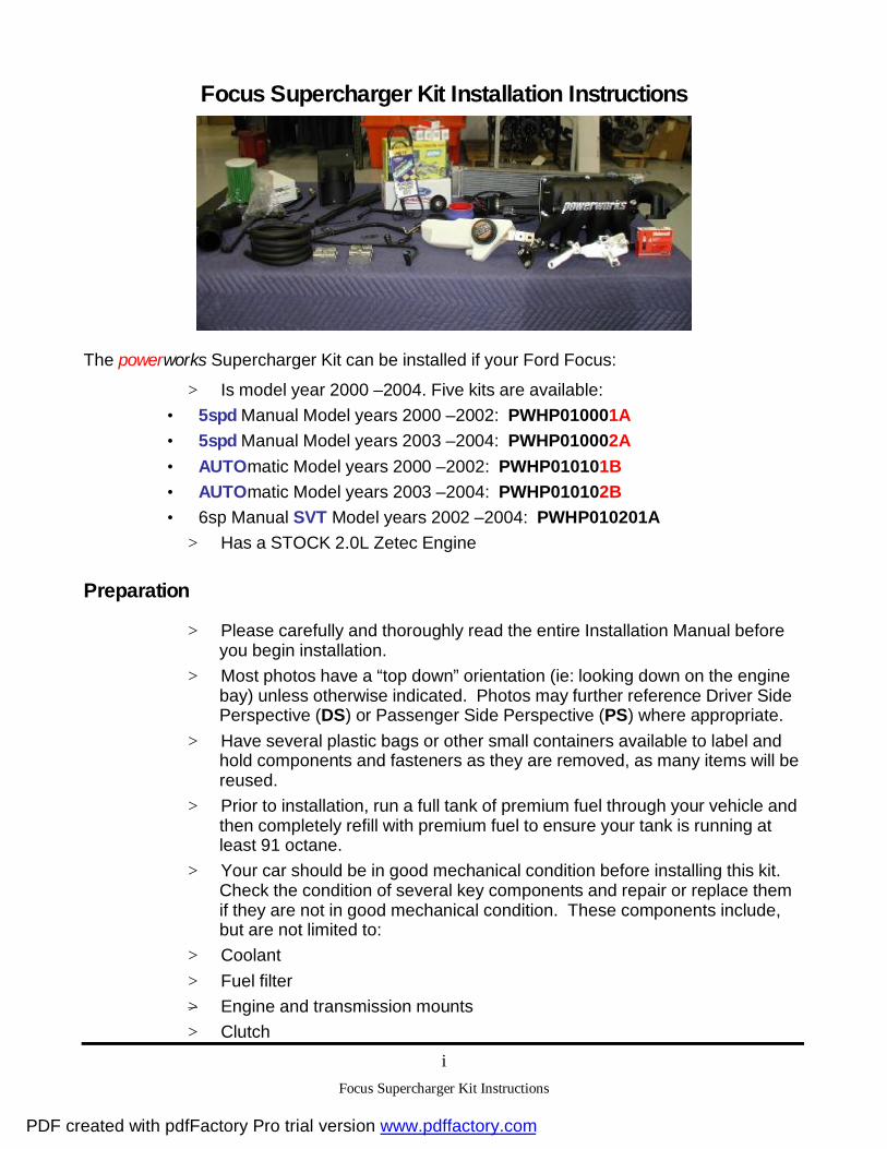
Focus Supercharger Kit Installation Instructions
The powerworks Supercharger Kit can be installed if your Ford Focus:
> Is model year 2000 – 2004. Five kits are available:
• 5spd Manual Model years 2000 – 2002: PWHP010001A
• 5spd Manual Model years 2003 – 2004: PWHP010002A
• AUTOmatic Model years 2000 – 2002: PWHP010101B
• AUTOmatic Model years 2003 – 2004: PWHP010102B
• 6sp Manual SVT Model years 2002 – 2004: PWHP010201A
> Has a STOCK 2.0L Zetec Engine
Preparation
> Please carefully and thoroughly read the entire Installation Manual before you begin installation.
> Most photos have a “top down” orientation (ie: looking down on the engine bay) unless otherwise indicated. Photos may further reference Driver Side Perspective (DS) or Passenger Side Perspective (PS) where appropriate.
> Have several plastic bags or other small containers available to label and hold components and fasteners as they are removed, as many items will be reused.
> Prior to installation, run a full tank of premium fuel through your vehicle and then completely refill with premium fuel to ensure your tank is running at least 91 octane.
> Your car should be in good mechanical condition before installing this kit. Check the condition of several key components and repair or replace them if they are not in good mechanical condition. These components include, but are not limited to:
> Coolant
> Fuel filter
> Engine and transmission mounts
> Clutch
PDF created with pdfFactory Pro trial version www.pdffactory.com
Focus Supercharger Kit Instructions
ii
> Water pump (install thread lock to the water pump pulley bolts for added safety)
> Further, depending on your driving habits, you may need to upgrade power train mounts to heavy duty aftermarket components.
> Adding a “water wetter”-type product to your engine coolant system is also recommended.
> Timing Belt
> Starter
Safety
> FOLLOW STANDARD SHOP SAFETY PRACTICES and EXERCISE COMMON SENSE. Responsibility for your vehicle and your safety is yours.
> Always wear eye protection.
> Do not allow flames, sparks, or other heat sources near the battery, wiring, or fuel lines (use extra zip ties or clamps if necessary to secure loose hoses and wires).
> Allow the engine to run only in a well-ventilated area.
> Cover fuel lines with a towel or shop rag before disconnecting to absorb any fuel that may still be in the line.
> Immediately clean any fuel spills and dispose of materials properly.
> With the supercharger installed, your car will be substantially faster. Ensure that other components on the car, such as tires and brakes, are equipped to handle this extra speed.
> You should NOT use a supercharged Focus to tow a trailer.
Service
Adding a supercharger to your car demands increased attention to service. You should perform the following maintenance items, in addition to those listed in your owner’s manual:
> Check the accessory drive belt for wear at 10,000 miles and every 5000 miles thereafter. Call powerworks for a replacement belt or locally locate a suitable 6-rib replacement (’00-02 5spd/AUTO and SVT = 87.5” long, ’03-04 5spd/AUTO = 86.5” long)
> After completing the supercharger kit install, drive the car 50-100 miles and then verify all new components are still tightly fastened.
> Clean and re-oil your air filter as necessary, depending on your driving conditions. Cleaning kits are available at most auto parts stores.
> Change your oil and filter with full synthetic 5W30 oil every 3000 miles.
PDF created with pdfFactory Pro trial version www.pdffactory.com

Focus Supercharger Kit Instructions
iii
For Occasional Track Use
Although the powerworks Supercharger Kit is not warranted for racing, occasional racetrack use is acceptable when you follow these guidelines:
> Change all fluids before and after track events.
> Use an “air-blast” oil cooler – the remote oil filter adapter has an extra inlet and outlet to make installation easier. When installing the heat exchanger, however, do not block the engine coolant radiator or the intercooler radiator.
> Recommend using aftermarket urethane engine and transmission mounts.
> Recommend the use of a limited slip differential - “Quaife”, “Torsen”, etc…..
> The fuel pump in 2000-2002 models should be upgraded to the 2003+ Focus fuel pump. Contact powerworks before doing this, as a new calibration will be required, which can be supplied to you by powerworks for a nominal fee.
Disclaimer
The following instructions are general guidelines for installing the powerworks Supercharger Kit. The photos shown may differ slightly from your car, especially if other modifications have been made to your vehicle.
If you have any doubt about your mechanical ability to perform this installation, please have the supercharger installed by a trained professional.
If you choose to install the kit yourself and have questions about installation, or need replacement (service) parts, please call our technical support line:
Technical Support 248.473.WORKS (phone)
Monday – Friday: 9:00 am– 4:00 pm (EST) 248.471.3680 (fax)
MAHLE Powertrain, Inc.
41000 Vincenti Court Novi, Michigan 48375
Please note: The latest version of this instruction manual is always available on the powerworks website. Be sure to check the “In the Garage” section of the website for any updates to this manual as well as helpful hints on installation.
www.powerworks.net
PDF created with pdfFactory Pro trial version www.pdffactory.com

Focus Supercharger Kit Instructions
iv
Required Tools
• Ratchet drive with assorted extensions and swivel
• 10mm socket
• 8mm socket
• 13mm socket
• 1 1/16” wrench
• Needle nose pliers
• 7mm socket
• Small flathead screwdriver or pick
• Large flathead screwdriver
• 10mm deep well socket
• E8 inverted Torx socket
• 15mm wrench
• Prybar
• 15mm socket
• Torx bits: T15, T20, T27, T40
• Security Torx bit: T20H (hole in center)
• Hex (Allen) keys or bits: 3mm, 3/8”, 8mm
• 7/8” socket
• 7/8” wrench
• Drill and 1/8” drill bit
• 3/8” nut driver or socket
• Paint pen (or other marking instrument)
• File or belt sander or die grinder
• Hose cutter or knife
• 5/8” (spark plug) socket
• 5/16” Fuel-line disconnect tool
• Ratchet Strap
• Jack and jack stands (2 minimum)
Other Items Required
• Thread sealing tape (TFE)
• Assorted zip ties (approx. 10)
• Shop rags or towels
• Liquid thread lock
• Fully synthetic 5W30 oil (approx. 5 quarts) and favorite coolant (1 gallon)
PDF created with pdfFactory Pro trial version www.pdffactory.com

powerworks DISASSEMBLY
Focus Supercharger Kit Instructions
1
1. Remove the battery cover.
2. Disconnect the battery cables (negative, then positive) and remove the battery and battery tray from the vehicle.
3. From inside the passenger compartment, pull the passenger side plastic kick-panel trim and locate the Engine Control Module (ECM) (behind the glove box). (DS)
4. Use a 10mm socket to disconnect the harness from the ECM. Slide the ECM from the plastic retainer and remove it from the car.
5. Package the ECM into the pre-paid shipping envelope supplied and send it to powerworks for a calibration update. powerworks will return your PCM via overnight express. See orange insert for additional instructions.
PDF created with pdfFactory Pro trial version www.pdffactory.com

powerworks DISASSEMBLY
Focus Supercharger Kit Instructions
2
6. Disconnect the mass airflow sensor harness, located on top of the air intake tube.
7. Disconnect the breather tube from the cam cover.
8. Remove the air box assembly and clean air duct from the engine bay by loosening the clamp at the throttle body and then firmly pulling the air box upward out of the rubber retention grommets. Leave the grommets in the body for later use.
9. Disconnect the vacuum harness from the Exhaust Gas Recirculation (EGR) valve.
10. Use a 1-1/16” wrench to disconnect the EGR tube from the bottom of the EGR valve. Remove the 10mm-head EGR attachment bolts to remove the EGR valve.
NOTE: SVT DOES NOT have an EGR system. Please ignore the EGR and DPFE steps.
PDF created with pdfFactory Pro trial version www.pdffactory.com

powerworks DISASSEMBLY
Focus Supercharger Kit Instructions
3
11. Remove the throttle cable clip. Disconnect the throttle cable and cruise control cable from the throttle body. Remove both from the throttle cable bracket. Set the cables aside, out of the engine bay.
12. SVT Remove the Intake Manifold Runner Control (IMRC) cable.
IMPORTANT: DO NOT BEND OR CRIMP CABLES.
13. Use a special 5/16” fuel line removal tool to disconnect the fuel line from the supply tube at the dash panel. (PS)
CAUTION: WRAP A RAG AROUND THE CONNECTION WHILE DISCONNECTING TO ABSORB ANY RESIDUAL FUEL IN THE LINE.
14. Disconnect the vacuum reference line from the Vapor Management Valve (VMV) (located on the passenger-side bulkhead). Squeeze the connector to disconnect the purge vapor hose.
PDF created with pdfFactory Pro trial version www.pdffactory.com

powerworks DISASSEMBLY
Focus Supercharger Kit Instructions
4
15. Disconnect the brake booster vacuum hose from the brake booster assembly (located below and behind the fuse box on the driver’s side).
16. Disconnect the electrical connector and hoses from the Delta Pressure Feedback Exhaust (DPFE) sensor (located in the center of the bulkhead). Remove the hoses from the vehicle. This step does not apply to Model Year 2001 vehicles, as the DPFE Sensor in these vehicles is located directly on the EGR tube.
17. Disconnect the electrical connector and vacuum lines from the Electronic Vacuum Regulator (EVR) solenoid (located in the top center of the bulkhead). Remove the solenoid from the vehicle and save for later use.
18. Remove the brake fluid reservoir assembly from the dash panel WITHOUT DISCONNECTING THE BRAKE LINES. You will have to bleed the brake lines if they become disconnected.
PDF created with pdfFactory Pro trial version www.pdffactory.com

powerworks DISASSEMBLY
Focus Supercharger Kit Instructions
5
19. Disconnect the Throttle Position Sensor (TPS), located on the driver’s side of the throttle body.
20. Disconnect the fuel injectors by pushing in on the wire retainers with a small, flathead screwdriver while carefully lifting the plastic harness block.
21. Disconnect the fuel pressure sensor.
22. Remove the bolt holding the coolant reservoir to the fender, release the tab at the rear of the reservoir, and move the bottle aside, out of the engine bay.
PDF created with pdfFactory Pro trial version www.pdffactory.com

powerworks DISASSEMBLY
Focus Supercharger Kit Instructions
6
23. Disconnect the Cylinder Head Temperature (CHT) sensor.
24. Disconnect the vacuum line from the fuel pressure sensor and remove the fuel rail and fuel injectors using an 8mm socket.
IMPORTANT: TAPE OVER THE INJECTOR HOLES TO KEEP OBJECTS FROM ENTERING THE ENGINE.
CAUTION: SOME FUEL MAY SPILL – CLEAN UP IMMEDIATELY.
25. Lift the power steering reservoir out of the mounting bracket and set the bottle aside, out of the engine bay.
26. Disconnect the main injector harness plug along with the oil pressure sending unit, knock sensor, cam position sensor, and IAC plug. You can then remove the harness from the vehicle.
PDF created with pdfFactory Pro trial version www.pdffactory.com

powerworks DISASSEMBLY
Focus Supercharger Kit Instructions
7
27. Remove the PCV hose from the crossover tube at the back of the engine, below the ignition coil.
28. Remove the passenger-side engine lifting eye and the intake support bracket. Remove the lifting eyebolt first, separating it from the manifold support (the intake support will not be reused). The lifting eye can be set aside, with the ground wire still attached. Remove and discard the support bracket.
29. Remove the camshaft Position sensor from the head. Use a T40 Torx bit for 5sp Base and Auto: use a 8mm socket for SVT.
30. SVT Disconnect the intake manifold runner clamps and separate the intake manifold. From below the vehicle, remove the lower mounting bolt using an 8mm socket or wrench.
PDF created with pdfFactory Pro trial version www.pdffactory.com

powerworks DISASSEMBLY
Focus Supercharger Kit Instructions
8
31. Remove all intake manifold fasteners (2 nuts and 5 bolts) from the head. You may need to access the middle bolt from underneath.
32. Remove the studs (2) from the head with an inverted Torx (E8) bit.
33. Raise the front of the vehicle onto jack stands.
CAUTION: USE CARE TO ENSURE THE VEHICLE IS STABLE ON THE STANDS.
32. Remove both front wheels and the plastic drivers-side inner splash shield (splash shield secured with a Torx-head screw, 8mm-head screw and five push-in plastic fasteners).
33. Remove the engine roll restrictor from the sub-frame and transmission.
34. SVT Remove the fan pack. The engine will need to be rocked slightly to allow clearance. The fan pack is removed from under the vehicle.
PDF created with pdfFactory Pro trial version www.pdffactory.com

powerworks DISASSEMBLY
Focus Supercharger Kit Instructions
9
35. Remove the mounting bolts from the passenger side engine mount. Using a pry bar move the engine mount forward as shown.
36. Remove the intake manifold assembly, and all associated vacuum lines, from the vehicle.
IMPORTANT: BE SURE TO TAPE OVER CYLINDER HEAD INTAKE PORTS
37. If required, disconnect the exhaust at the flex-pipe (either end will work) if necessary to gain more movement in moving the engine forward.
PDF created with pdfFactory Pro trial version www.pdffactory.com

powerworks DISASSEMBLY
Focus Supercharger Kit Instructions
10
38. If an accessory drive belt guard is fitted to your vehicle, remove and retain.
39. Remove the accessory drive belt and discard it. As the drive belt will not be reused, you may cut the belt for easier removal.
40. Disconnect the harness from the alternator, remove the front/rear alternator mounting bolts from the mounting bracket and remove the alternator.
41. Remove the alternator bracket fasteners - 3 bolts and 1 nut.
42. Use an E8 inverted Torx socket to remove the alternator bracket mounting stud from the block. Remove the alternator bracket.
PDF created with pdfFactory Pro trial version www.pdffactory.com

powerworks DISASSEMBLY
Focus Supercharger Kit Instructions
11
43. Disconnect and remove the cruise control module from the bulkhead, if applicable.
NOTE If your vehicle has the cruise control cable end shown, the cable assembly must be replaced with Ford P/N 3S4Z-9A825-BA.
44. Remove oil filter.
45. SVT Use locking pliers to clamp off the oil cooler coolant lines, otherwise carefully drain coolant. If possible drain into clean catch bucket, so coolant can be reused. Remove oil cooler lines, oil cooler, and oil cooler gasket from engine block.
46. Remove the original cold air duct.
PDF created with pdfFactory Pro trial version www.pdffactory.com

powerworks SUBASSEMBLY PREPARATION
Focus Supercharger Kit Instructions
12
1. On 2000 – 2002 MY vehicles remove the throttle cable bracket from the production throttle body. On 2003 – 2004 MY vehicles use the new bracket supplied in the kit. Install the bracket on the new throttle body (screws supplied in throttle body box). The stock throttle body may need to be removed from the intake to perform this task.
2. On SVT and 2000 – 2002 MY vehicles remove the TPS from the production throttle body. On 2003 -2004 MY vehicles use the new TPS supplied in the kit. Install the TPS on the new throttle body using the screws provided in the throttle body box.
3. Remove the bolt holding the pulley onto the factory belt tensioner. Re-use the washer and the M8 bolt (provided) to attach the new idler pulley (provided) to the new tensioner-bracket. (Refer to Installation Step 35)
4. Remove the stock tensioner from the alternator bracket.
PDF created with pdfFactory Pro trial version www.pdffactory.com

powerworks SUBASSEMBLY PREPARATION
Focus Supercharger Kit Instructions
13
5. 5sp and AUTO Modify the alternator bracket by removing the area shown in red above by filing or grinding.
IMPORTANT: PERFORM THIS OPERATION AWAY FROM THE ENGINE BAY TO PREVENT DEBRIS FROM ENTERING THE ENGINE
6. Attach the new tensioner (supplied in kit) to tensioner-bracket using the original tensioner bolts. Sufficiently tighten bolts with thread-locker.
7. Attach the tensioner bracket to the alternator bracket (bolts supplied). Do not tighten these bolts yet, as you will need to properly locate the supercharger (S/C) snout support first, (Refer to Installation Step 35).
PDF created with pdfFactory Pro trial version www.pdffactory.com

powerworks SUBASSEMBLY PREPARATION
Focus Supercharger Kit Instructions
14
Step 8 – Vacuum Hose Routing
5spd & AUTO
Vacuum Pad at Bottom of Intake Neck
Fit the vacuum hoses to the supercharger according to the photos above. You may choose to connect the brake booster line to the vehicle side first and then connect to the supercharger after it has been installed. Also, connect the supercharger boost bypass solenoid now using the closest vacuum fitting on the vacuum tree.
SVT
Vacuum Pad on Back of Intake Neck
Fit the vacuum hoses to the supercharger according to the photos above. You may choose to connect the brake booster line to the vehicle side first and then connect to the supercharger after it has been installed. Also, connect the supercharger boost bypass solenoid now using the closest vacuum fitting on the vacuum tree.
PDF created with pdfFactory Pro trial version www.pdffactory.com

powerworks SUBASSEMBLY PREPARATION
Focus Supercharger Kit Instructions
15
9. AUTO Remove bracket from cruise control module.
10. AUTO Peel off paper backing from double-sided tape on new cruise module bracket. Attach the new cruise control module bracket with the supplied screws.
PDF created with pdfFactory Pro trial version www.pdffactory.com
Powerworks INSTALLATION
Focus Supercharger Kit Instructions
16
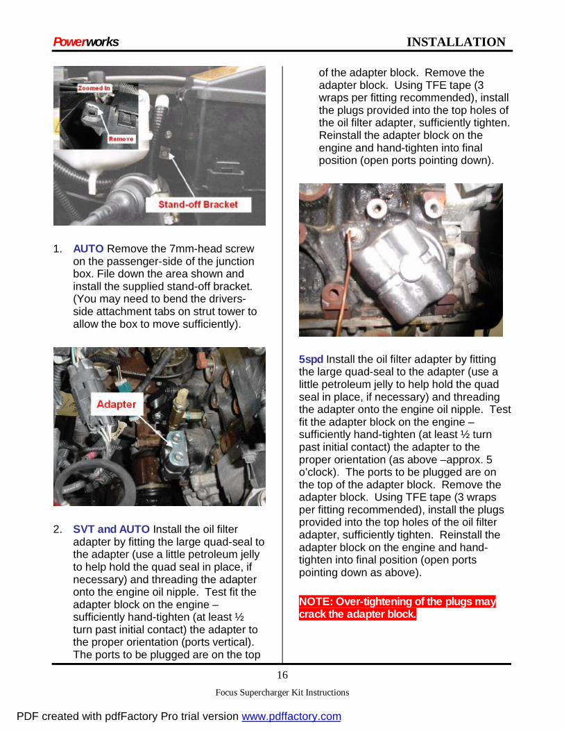
1. AUTO Remove the 7mm-head screw on the passenger-side of the junction box. File down the area shown and install the supplied stand-off bracket. (You may need to bend the drivers-side attachment tabs on strut tower to allow the box to move sufficiently).
2. SVT and AUTO Install the oil filter adapter by fitting the large quad-seal to the adapter (use a little petroleum jelly to help hold the quad seal in place, if necessary) and threading the adapter onto the engine oil nipple. Test fit the adapter block on the engine – sufficiently hand-tighten (at least ½ turn past initial contact) the adapter to the proper orientation (ports vertical). The ports to be plugged are on the top
of the adapter block. Remove the adapter block. Using TFE tape (3 wraps per fitting recommended), install the plugs provided into the top holes of the oil filter adapter, sufficiently tighten. Reinstall the adapter block on the engine and hand-tighten into final position (open ports pointing down).
5spd Install the oil filter adapter by fitting the large quad-seal to the adapter (use a little petroleum jelly to help hold the quad seal in place, if necessary) and threading the adapter onto the engine oil nipple. Test fit the adapter block on the engine – sufficiently hand-tighten (at least ½ turn past initial contact) the adapter to the proper orientation (as above – approx. 5 o’clock). The ports to be plugged are on the top of the adapter block. Remove the adapter block. Using TFE tape (3 wraps per fitting recommended), install the plugs provided into the top holes of the oil filter adapter, sufficiently tighten. Reinstall the adapter block on the engine and hand-tighten into final position (open ports pointing down as above).
NOTE: Over-tightening of the plugs may crack the adapter block.
PDF created with pdfFactory Pro trial version www.pdffactory.com

Powerworks INSTALLATION
Focus Supercharger Kit Instructions
17
5spd Using TFE tape (3 wraps per fitting recommended) install the supplied AN union fittings into the lower ports.
NOTE: Over-tightening of the fittings may crack the adapter block.
5spd Connect the steel lines (provided) to the AN fittings but do not yet tighten. DO NOT use any TFE tape on these fittings as they have a built-in tapered seal. The two steel extension lines are different. Use care when installing to ensure the lines fit close to the engine block and AWAY from the driveshaft.
3. Remove the through-bolt from the lower supercharger-mounting bracket.
4. Loosely fit the supercharger-mounting bracket to the block using only the top and driver-side bolts provided. 5spd and AUTO Install the two provided spacers behind the drivers-side of bracket and engine block (Note cut out on backside of bracket). ’02-03 SVT may require the use of one spacer between the drivers-side of bracket and engine block.
NOTE: If the bolts are difficult to turn, run an M10x1.5 tap through the holes in the block.
PDF created with pdfFactory Pro trial version www.pdffactory.com

Powerworks INSTALLATION
Focus Supercharger Kit Instructions
18
5. SVT and AUTO Remove the two bellhousing bolts below the starter as shown.
6. SVT and AUTO Install rear S/C support bracket using provided M10x60 bolt as shown and one of the original bolts.
PDF created with pdfFactory Pro trial version www.pdffactory.com

Powerworks INSTALLATION
Focus Supercharger Kit Instructions
19
7. SVT ONLY Disconnect shifter cables and remove from existing bracket. Remove bracket and shift linkage counter weight. Install new shifter cable bracket supplied with kit. Re-install shifter cable and adjust as needed. Disconnect upper shift cable from linkage and bracket - upper shift cable needs to be final installed in bracket after S/C is installed. Do not re-install counter weight. For preventative maintenance you may wish to use zip ties, to hold shift cables in place over the ball clips. This will help prevent the shift cables from popping off during aggressive shifting.
PDF created with pdfFactory Pro trial version www.pdffactory.com

Powerworks INSTALLATION
Focus Supercharger Kit Instructions
20
8. SVT ONLY Remove rear catalyst heat shield and modify as shown.
9. SVT and Auto Using TFE tape (3 wraps per fitting recommended), install one (1) M8-tapped brass plug and one (1) steel plug into the remote filter mount as shown.
Note: If an oil temperature gauge is desired, replace the steel plug with the gauge sender/adapter parts supplied with the gauge.
10. SVT and Auto Install the remote filter adapter on the filter relocation bracket with four M8 bolts and three washers and nuts provided in the kit.
11. SVT ONLY Install the oil cooler using the original oil cooler gasket onto the remote filter adapter.
12. SVT ONLY Remove IMRC module and bracket. Driver side inner fender well.
PDF created with pdfFactory Pro trial version www.pdffactory.com

Powerworks INSTALLATION
Focus Supercharger Kit Instructions
21
13. SVT and Auto Drill out existing hole in drivers-side frame rail (as shown) to 11/32”. Temporarily attach the relocation bracket on the frame rail with a supplied M8 bolt/nut and mark/drill the two lower bracket hole locations if necessary (11/32”). SVT ONLY Use the lower holes from the removed IMRC bracket to attach the relocation bracket on the frame rail. Mark and drill the upper hole.
14. SVT and Auto Attach the filter relocation bracket to the frame with the supplied M8 bolts, washers and nuts.
15. SVT ONLY Relocate the oil cooler line coming from the radiator cross over tube, size and cut the hose to length from the cross over tube to the oil cooler. Attach the hose to the oil cooler. Cut the other oil cooler line past the 90 degree bend after the heater core. Splice together with the hose, adapter and clamps supplied in the kit. Route the hose and connect to the oil cooler.
16. SVT and Auto Route supplied oil hoses through the drivers-side inner fender access hole. Hoses run between the ABS module and brake booster, above the brake lines and cruise module at the back of the engine compartment.
PDF created with pdfFactory Pro trial version www.pdffactory.com

Powerworks INSTALLATION
Focus Supercharger Kit Instructions
22
17. SVT and Auto From underneath the vehicle, note the outlet port of the engine oil adapter block. Choose the appropriate hose assembly that would attach to the outlet port and label the other end of that hose ‘IN’ for attachment to the filter relocation block.
IMPORTANT: SOME OIL FILTERS USE A CHECK VALVE TO PREVENT OIL FROM DRAINING BACK INTO THE ENGINE. IF THE HOSES ARE REVERSED, THE ENGINE WILL BE STARVED OF OIL, CAUSING IRREVERSIBLE DAMAGE. BOTH CASTINGS HAVE ARROWS TO ASSIST IN VERIFYING OIL FLOW.
18. SVT and Auto Underneath the vehicle, using TFE tape (3 wraps per fitting recommended), attach the oil hoses to the engine oil adapter block (in-board hose first) and sufficiently tighten.
19. SVT and Auto In the drivers-side wheel well, route the oil hoses as shown (secure lines with P-Clips and zip ties.). Using TFE tape (3 wraps per fitting recommended), attach the appropriate hose to the appropriate port on the filter relocation block (‘IN’ should be outboard) and sufficiently tighten.
20. AUTO Install the oil filter onto the relocation block. SVT Install the oil filter onto the oil cooler.
21. SVT and AUTO Re-install the plastic drivers-side inner splash shield.
22. Remove the tape previously applied to the cylinder head face. Be sure to thoroughly clean head face of any adhesive residue.
PDF created with pdfFactory Pro trial version www.pdffactory.com

Powerworks INSTALLATION
Focus Supercharger Kit Instructions
23
23. Using two people, lower the new powerworks Supercharger assembly down behind the engine, pulley first.
24. Install the four (4) rubber intake gaskets supplied into the grooves machined into the new supercharger intake manifold.
25. Begin to re-connect the fuel injector harness by connecting the oil pressure sensor and knock sensor from below.
IMPORTANT: THE HARNESS MUST BE ROUTED AROUND THE #1 (PASSENGER-SIDE) CYLINDER RUNNER, NOT BETWEEN THE RUNNERS.
26. Loosely install the intake manifold to the head using the flange bolts provided.
27. Loosely install the S/C through bolt, attaching the supercharger to the engine block mounting bracket.
28. Loosely install the third mounting bracket bolt (may be necessary to grind away some of the bolt head flange).
PDF created with pdfFactory Pro trial version www.pdffactory.com

Powerworks INSTALLATION
Focus Supercharger Kit Instructions
24
29. Loosely install the transmission support bolt, using the shims supplied where necessary. 5spd Bolt points from engine to transmission (threads in transmission boss). SVT and AUTO Bolt points from transmission to engine (threads into rear s/c support bracket). More than one shim may be required. Sufficiently tighten all lower bolts (S/C through bolt, transmission support bolt, and three engine block mounting bolts).
30. Sufficiently tighten the intake flange bolts, using a criss-cross pattern, as illustrated above. Bolts 2/4/5 can be accessed from the passenger-side where the alternator normally resides.
PDF created with pdfFactory Pro trial version www.pdffactory.com

Powerworks INSTALLATION
Focus Supercharger Kit Instructions
25
31. SVT ONLY Install the upper shift cable into the shift cable bracket and adjust if needed. Zip tie cable end to linkage for extra retention. Note the shift cable routing, refer back to step 8 if needed.
32. Connect the other end of the brake booster vacuum hose to the brake booster.
33. Remove the Idle Air Control (IAC) from the production intake manifold. Install the stock IAC on the powerworks intake manifold using the new flat gasket (supplied in kit).
NOTE: IAC MUST be installed in the orientation shown for proper operation.
PDF created with pdfFactory Pro trial version www.pdffactory.com

Powerworks INSTALLATION
Focus Supercharger Kit Instructions
26
34. Install the alternator/tensioner bracket assembly into place from above and install the M8 Torx-head stud along with the three alternator bracket bolts and nut.
35. Install the lower 8mm-head tensioner bracket bolt and sufficiently tighten. Position the supercharger snout support bracket (see Subassembly Step 3) to be snug up against the supercharger and then sufficiently tighten both 10mm-head tensioner bracket mounting bolts.
36. Install the supplied idler pulley with supplied bolt and carry-over washer to the tensioner bracket and sufficiently tighten bolt.
37. 5spd Add the supplied P-clamp to the steel oil lines, fastening it underneath the lower tensioner bracket bolt. Now tighten the steel oil line nuts to the AN union adapters.
38. Re-install the alternator assembly and make all necessary connections.
PDF created with pdfFactory Pro trial version www.pdffactory.com

Powerworks INSTALLATION
Focus Supercharger Kit Instructions
27
39. Install the new drive belt and route the belt as shown above (or reference the under-hood decal supplied with re-flashed ECM). Move the tensioner to the maximum open position by turning the tensioner pulley bolt clockwise with a 14mm wrench and wrap belt around A/C compressor last.
PDF created with pdfFactory Pro trial version www.pdffactory.com

Powerworks INSTALLATION
Focus Supercharger Kit Instructions
28
40. Finish installing the new PCV hose by attaching it to the metal tube on the engine block located under the coil.
41. From underneath the vehicle, re-fit the cruise control module on the bulkhead.
42. Re-position engine mounts and re-install the engine mount bolts - sufficiently tighten bolts.
43. SVT ONLY Reinstall the fan pack and make all necessary connections.
44. Re-install the camshaft position sensor. Re-connect the electrical connector.
45. 5spd and AUTO Thoroughly clean the mounting flange on the EGR valve and install it on the supercharger manifold using the new gasket (supplied in kit). DO NOT TIGHTEN the mounting bolts until the tube has been re-installed into the valve bottom (2 13mm tube mounting bolts on the cylinder head may need to be loosened). Tighten the whole assembly once all connections are made. Connect the EGR vacuum line. SVT Install the EGR block-off plate and gasket supplied in the kit.
PDF created with pdfFactory Pro trial version www.pdffactory.com

Powerworks INSTALLATION
Focus Supercharger Kit Instructions
29
46. Re-install the brake fluid reservoir to the dash panel.
47. Finish installing the new vapor line by attaching the other quick-connect fitting to the Vapor Management Valve (VMV). Also, connect the smaller vacuum control line to the VMV. (PS)
48. Re-install the EVR solenoid on the driver-side set of holes, regardless of where the solenoid was originally located (varies by model). Connect the small vacuum line and reconnect the original electrical harness.
49. 5spd and AUTO Re-install the Delta PFE sensor using the new rubber hoses (provided) and reconnect the original electrical harness. Remember that this step does not apply to Model Year 2001 vehicles.
IMPORTANT: THE HOSES ARE DIFFERENT SIZES. EACH HOSE MUST BE ATTACHED TO THE APPROPRIATE CONNECTION. BE CERTAIN THEY ARE RE-ATTACHED PROPERLY. INCORRECT INSTALLATION WILL CAUSE THE EGR TO MALFUNCTION AND TRIGGER A MIL LIGHT.
PDF created with pdfFactory Pro trial version www.pdffactory.com

Powerworks INSTALLATION
Focus Supercharger Kit Instructions
30
50. Re-install the engine-lifting eye without the intake support. Reattach the ground strap (if previously disassembled).
51. Remove the fuel rail and supply hose from the stock intake manifold. The supply hose need not be separated from the rail.
52. Remove the stock fuel injectors by prying the clips off the rail and gently pulling the injectors out of the rail. Ensure all O-rings are removed with the injectors, or the new injectors cannot be inserted.
53. Install the new injectors into the rail, using a small amount of mineral oil (or similar lubricant) on the seals.
54. SVT ONLY Rotate fuel pulse damper approximately 180 deg.
PDF created with pdfFactory Pro trial version www.pdffactory.com

Powerworks INSTALLATION
Focus Supercharger Kit Instructions
31
55. Install the injector and fuel rail assembly into the intake manifold runners using the original bolts. You may want to test fit the injector harness before pushing the injectors into the manifold by routing the appropriate connectors to each sensor and verifying the wire lengths.
56. SVT ONLY As you tighten the fuel rail into place, you will need to slightly bend the inlet fuel line away from the manifold. Insert a punch into the fuel line and carefully bend inlet to the position shown above as you tighten fuel rail.
57. Route the remaining injector harness wiring as shown.
PDF created with pdfFactory Pro trial version www.pdffactory.com

Powerworks INSTALLATION
Focus Supercharger Kit Instructions
32
58. Re-connect the fuel jumper hose to the supply tube on the bulkhead.
59. Install and tighten the supplied IAT sensor in the intake manifold as shown.
60. Install the single vacuum boost line between the fuel pressure sensor and one of the 1/8” barbed fittings on the upper intake manifold.
Note that the second 1/8” barbed port is used for a boost gauge. If you are not using a boost gauge, leave this cap in place and secure with a zip tie, if necessary.
61. Install the intercooler pump relay harness by removing the ground bolt on the driver side fender (inside the engine bay) and attaching the relay to the body with the bolt (existing ground under relay). Alternately, you may leave this ground junction intact and attach the relay to the body with a self-tapping screw. (DS)
PDF created with pdfFactory Pro trial version www.pdffactory.com

Powerworks INSTALLATION
Focus Supercharger Kit Instructions
33
62. Remove one of the ground bolts underneath the transmission/air box bracket. Re-install the ground you just removed, along with the ground eyelet for the intercooler pump, in this ground location. Insure all grounds are reconnected; otherwise vehicle may not start. (DS)
63. Route the single pin trigger wire toward the throttle body and the two-pin pump connector down toward the driver’s side of the radiator. These two connections will be made in subsequent steps.
64. Install the Idle Air Control valve (IAC) jumper harness, routing the harness behind and around the throttle body inlet and AWAY from the EGR valve.
65. Attach the intercooler pump control harness trigger wire to the single pin connector on the IAC jumper harness.
PDF created with pdfFactory Pro trial version www.pdffactory.com

Powerworks INSTALLATION
Focus Supercharger Kit Instructions
34
66. Install TPS to the throttle body using the supplied screws (in throttle body box).
67. Install the new throttle body assembly using the supplied bolts and gasket.
68. Connect and route the TPS jumper harness behind and around the throttle body inlet and AWAY from the EGR valve. Route all jumper harnesses away from heat sources such as the EGR tube or valve to avoid any potential damage caused by heat.
69. Route the throttle and cruise control cables to avoid kinking or binding in the cable and to prevent any contact with the exhaust manifold. Move the original factory throttle cable clip to the driver’s side of the heater hose. The cable will be re-routed under the air filter assembly, instead of the original location over the exhaust manifold.
70. Connect the cables to the throttle body cable bracket and correct lever posts and check for functionality.
PDF created with pdfFactory Pro trial version www.pdffactory.com

Powerworks INSTALLATION
Focus Supercharger Kit Instructions
35
71. Cut approximately 1-1/2” from the short end of the two (2) formed rubber hoses (labeled 4206 and 4207).
72. Use the clamps provided to attach the shorter of the two (2) formed hoses (labeled 4206) to the rear intercooler fitting and the intercooler reservoir bottle. The short end of the rubber hose will attach to the intercooler, while the other end will attach to the upper fitting on the bottle. The hose should go under the electrical connections and under the power steering bottle and hoses. You may want to zip tie this intercooler hose to the vapor line or another convenient location to ensure the hose does not contact the accessory belt.
73. If brackets are not a part of the reservoir bottle, attach mounting brackets with supplied screws.
74. Attach one end of the longer straight rubber hose to the lower fitting of the intercooler reservoir bottle and route the hose down into the inner fender.
PDF created with pdfFactory Pro trial version www.pdffactory.com
Powerworks INSTALLATION
Focus Supercharger Kit Instructions
36
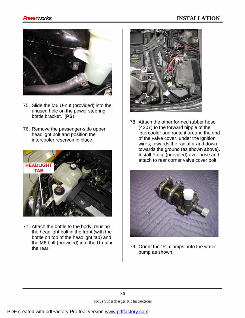
75. Slide the M6 U-nut (provided) into the unused hole on the power steering bottle bracket. (PS)
76. Remove the passenger-side upper headlight bolt and position the intercooler reservoir in place.
77. Attach the bottle to the body, reusing the headlight bolt in the front (with the bottle on top of the headlight tab) and the M6 bolt (provided) into the U-nut in the rear.
78. Attach the other formed rubber hose (4207) to the forward nipple of the intercooler and route it around the end of the valve cover, under the ignition wires, towards the radiator and down towards the ground (as shown above). Install P-clip (provided) over hose and attach to rear corner valve cover bolt.
79. Orient the “P”-clamps onto the water pump as shown.
PDF created with pdfFactory Pro trial version www.pdffactory.com

Powerworks INSTALLATION
Focus Supercharger Kit Instructions
37
80. Determine the proper mounting location for the pump and fasten it to the frame rail with the self-tapping screws provided. The pump should be mounted with the inlet forward, the outlet up and toward the center of the car (roughly at 45 degrees). Hold the pump against the frame rail, mark the hole locations, and then drill pilot holes with before attaching the pump directly to the frame. Connect the 2-pin electrical connector to the pump.
81. Connect the other end of the formed rubber hose (4207) to the outlet of the pump using one of the clamps provided. It may be necessary to trim some of the rubber hose, depending on the exact pump mounting location.
82. Install the Low Temperature Radiator (LTR) under the bumper beam and behind the lower bumper grill using the self-tapping fasteners supplied. You may need to remove some factory paneling to gain access to the underside of the bumper beam. Mark the LTR location and pre-drill pilot holes.
83. Connect and clamp the other end of the longer hose (attached to the intercooler reservoir outlet) to the inlet of the Low Temperature Radiator (LTR). Depending on the location of the LTR, you may need to trim the length of this hose.
84. Use the shorter intercooler hose and clamps (provided) to connect the LTR to the electric pump. Trim the hose if necessary for optimal fitment.
PDF created with pdfFactory Pro trial version www.pdffactory.com

Powerworks INSTALLATION
Focus Supercharger Kit Instructions
38
85. 5spd Using TFE tape, install two (2) barbed nipples and two (2) plugs into the remote filter mount as shown.
86. 5spd Install the remote filter adapter on the body rail using the self-tapping fasteners provided in the kit. Ensure the bottom of the filter points toward the outside of the car (passenger side). Hold the part against the frame rail, mark the hole locations, and then drill pilot holes. (PS)
87. 5spd Trim and install the oil hoses from the engine adapter to the filter adapter, ensuring the hoses are connected in the proper orientation for flow direction.
PDF created with pdfFactory Pro trial version www.pdffactory.com

Powerworks INSTALLATION
Focus Supercharger Kit Instructions
39
88. Re-install the roll restrictor using blue thread lock on the bolt.
89. Re-install accessory drive belt guard, if equipped and desired.
90. Re-install the factory coolant bottle and power steering reservoir.
91. Remove the air filter clamp from the air filter and thread it through the slot in the air tube-mounting base.
92. Install the new air induction base by pushing the three pins into the factory rubber grommets that remain in the body.
PDF created with pdfFactory Pro trial version www.pdffactory.com
Powerworks INSTALLATION
Focus Supercharger Kit Instructions
40
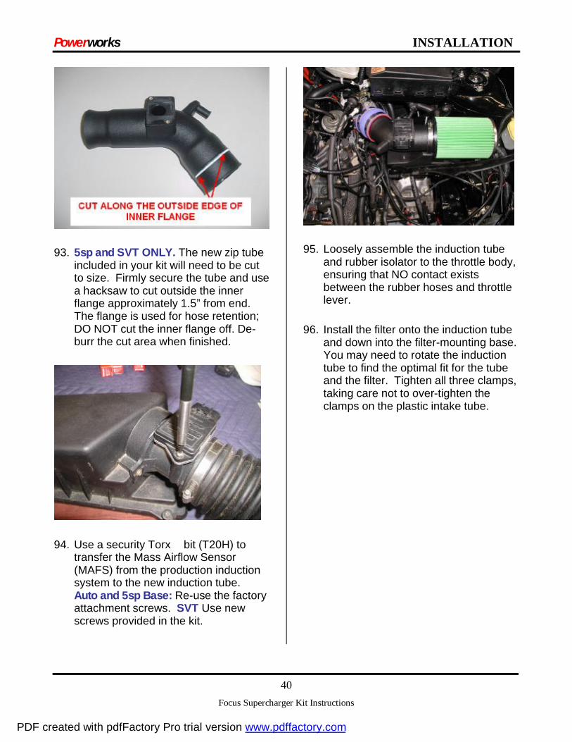
93. 5sp and SVT ONLY. The new zip tube included in your kit will need to be cut to size. Firmly secure the tube and use a hacksaw to cut outside the inner flange approximately 1.5” from end. The flange is used for hose retention; DO NOT cut the inner flange off. De-burr the cut area when finished.
94. Use a security Torx bit (T20H) to transfer the Mass Airflow Sensor (MAFS) from the production induction system to the new induction tube. Auto and 5sp Base: Re-use the factory attachment screws. SVT Use new screws provided in the kit.
95. Loosely assemble the induction tube and rubber isolator to the throttle body, ensuring that NO contact exists between the rubber hoses and throttle lever.
96. Install the filter onto the induction tube and down into the filter-mounting base. You may need to rotate the induction tube to find the optimal fit for the tube and the filter. Tighten all three clamps, taking care not to over-tighten the clamps on the plastic intake tube.
PDF created with pdfFactory Pro trial version www.pdffactory.com

Powerworks INSTALLATION
Focus Supercharger Kit Instructions
41
97. Re-install the closure tube from the cam cover to the fitting on the new air intake tube. SVT ONLY will require the tube to be cut to size. AUTO ONLY may require hose to be extended with provided hose and coupler.
98. Use a pick or very small flathead screwdriver to remove the yellow pin lock in the factory (6-pin) MAF connector.
99. First, pull the outer pins from the stock MAF connector (labeled “1” and “6” on the connector) and insert the two pins into the new 2-pin connector shell (provided). It does not matter which pin goes where in the new connector, but ensure the pins are inserted with the same orientation in which they were removed from the old connector. You will hear and feel a distinct click when the pins are installed correctly. Push the yellow pin lock into place on the two-pin connector.
PDF created with pdfFactory Pro trial version www.pdffactory.com

Powerworks INSTALLATION
Focus Supercharger Kit Instructions
42
100. Pull the remaining four pins from the MAF and insert them into the new 4-pin connector shell (provided) in the following locations. You may want to pull one pin out and reinsert it into the new connector before removing the next pin. Pin numbers are molded into the connectors for your reference:
a. Stock pin #5 to new pin #4 b. Stock pin #4 to new pin #3 c. Stock pin #3 to new pin #2 d. Stock pin #2 to new pin #1
101. Plug the supplied MAF and Air Charge Temperature (ACT) jumper harnesses into the new connectors.
102. Route the ACT jumper harness across the top of the intake manifold to the new ACT sensor (shown in the diagram) and connect the harness to the sensor. You may wish to zip tie the harness to the open hole in the coil bracket to prevent the harness from resting on the EGR tube.
103. 5spd and AUTO Remove the stock spark plugs and replace them with the new spark plugs provided. Verify the plug gap (1.14mm or .045”) before installation. SVT Remove spark plugs and verify plug gap (1.14mm or .045”).
104. Install the recalibrated Engine Control module back into the production location in the passenger foot well.
105. Fill the intercooler reservoir bottle with a 50/50 glycol/water mix until full to avoid running the coolant pump dry on the initial key up.
PDF created with pdfFactory Pro trial version www.pdffactory.com

Powerworks INSTALLATION
Focus Supercharger Kit Instructions
43
106. Re-install the battery into the vehicle.
107. Route the other end of the MAF jumper harness to the stock MAF connector.
108. Make the final coolant pump electrical connection to the battery positive cable.
109. Reconnect the battery and re-install the battery cover, if desired.
110. SVT ONLY If coolant was drained during oil cooler relocation Refill engine coolant, as needed. Use Ford recommended coolant.
111. Drain oil and refill with synthetic 5w30. (approx. 5 quarts)
112. Key on and off several times, searching for possible fuel and coolant leaks. Be certain to continue filling the coolant reservoir bottle each time the ignition is turned on.
113. With the key in the ON position, continue to fill the intercooler system until all air is purged from system. The engine need not be started to perform this operation.
114. Disconnect the coil harness (plug shown) and turn the engine over for 15-20 seconds to circulate oil throughout the new oil lines. Re-connect the coil harness when complete.
115. Start the engine and let it idle. Check for leaks in all systems: oil, air and coolant.
PDF created with pdfFactory Pro trial version www.pdffactory.com

Powerworks INSTALLATION
Focus Supercharger Kit Instructions
44
116. Apply your CARB E.O. decal (provided with your recalibrated ECM) under the hood as shown.
117. Apply the “premium fuel only” decal to a conspicuous place (e.g. inside the fuel door).
118. Check all fluid levels
119. Get out on the road and enjoy your new powerworks supercharged Focus! Re-check fastener tightness after the first 50 - 100 miles.
PDF created with pdfFactory Pro trial version www.pdffactory.com

Powerworks INSTALLATION
Focus Supercharger Kit Instructions
45
Troubleshooting
• If after initial engine warming, the engine does not seem to idle properly, follow this procedure to set the base idle RPM;
• Start the engine and let it warm-up until engine temp is stable (base idle = 850 RPM)
• Unplug the IAC connector. If the engine stalls, reset the throttle stop screw on the throttle body by turning clockwise half a turn.
• Restart the car holding the throttle slightly open, then slowly allow the throttle to rest against the stop screw. Adjust the idle speed to be 650 RPM (use an inductive tachometer if possible because it is more accurate than the factory tachometer).
• Turn the engine off, re-connect the IAC connector, and disconnect the battery for at least 20 seconds to clear all ‘check-engine’ codes – this will reset the ECM to allow IAC re-learning.
• Re-connect the battery and re-start the car. Let the car idle for a few minutes and then drive the car to verify functionality.
• Idle may need to be further adjusted depending on driving habits and accessory loading (ie. high alternator loads). The idle screw can vibrate loose over time – use a drop of blue thread lock to retain.
• If while driving the car, you experience a high-idle condition when coming to a stop, check that there is no interference between the throttle body lever and the bellows boot. The boot can be re-oriented or trimmed as necessary to allow for proper clearance.
DEALER SERVICE INFORMATION
Dealers using WDS (Worldwide Diagnostic System) and PDS (Portable Diagnostic System - Palm Version) to communicate with PCMs in Powerworks equipped vehicles may not be able to communicate with the PCM. WDS and PDS attempt to automatically "ID" the vehicle by checking the PCM Catchword / CAL ID, and does not recognize the ID in the Powerworks flashed module. Dealers can force WDS to communicate with the PCM by manually entering the PCM "Tear Tag" number (located on a white sticker on the PCM, and sometimes also located in the door jam), or by entering the PCM "Part Number" (located on the PCM part # sticker), or by entering the original vehicle calibration number (accessable to dealers by running a Ford OASIS printout using the VIN number from the vehicle).There should be no issues like this using NGS.
If you have any other issues,
please call the powerworks tech line at (248) 473-WORKS
PDF created with pdfFactory Pro trial version www.pdffactory.com