Embed Size (px)
Citation preview

PPCI7443 Advanced 4 Axes Servo / Stepper
Motion Control Card User's Guide
(Version : 2.00)

Table of Contents •••• i
Table of Contents
INTRODUCTION...................................................................................................... 1
1.1 FEATURES..................................................................................................... 4
1.2 SPECIFICATIONS............................................................................................ 5
1.3 SOFTWARESUPPORTING................................................................................ 6
1.3.1 Programming Library .......................................................................... 6
1.3.2 PPCI7443 Utility.................................................................................. 6
INSTALLATION....................................................................................................... 7
2.1 WHAT YOU HAVE ......................................................................................... 7
2.2 PPCI7443 OUTLINE DRAWING ...................................................................... 8
2.3 HARDWARE INSTALLATION............................................................................ 9
2.3.1 Hardware configuration....................................................................... 9
2.3.2 PCI slot selection ................................................................................. 9
2.3.3 Installation Procedures ........................................................................ 9
2.3.4 Trouble shooting: ................................................................................. 9
2.4 SOFTWAREDRIVER INSTALLATION .............................................................. 10
2.5 CN1 PIN ASSIGNMENTS: EXTERNAL POWERINPUT...................................... 10
2.6 CN2 PIN ASSIGNMENTS: MAIN CONNECTOR................................................ 11
2.7 CN3 PIN ASSIGNMENTS: MANUAL PULSERINPUT........................................ 12
2.8 CN4 PIN ASSIGNMENTS: SIMULTANEOUS START/STOP................................. 12
2.9 CN5 PIN ASSIGNMENT: TTL OUTPUT......................................................... 13
2.10 JUMPERSETTING FORPULSEOUTPUT .......................................................... 13
2.11 SWITCH SETTING FOREL LOGIC.................................................................. 14
SIGNAL CONNECTIONS...................................................................................... 15
3.1 PULSEOUTPUTSIGNALS OUT AND DIR...................................................... 16
3.2 ENCODERFEEDBACK SIGNALS EA, EBAND EZ........................................... 18
3.3 ORIGIN SIGNAL ORG .................................................................................. 21
3.4 END-LIMIT SIGNALS PELAND MEL............................................................ 22
3.5 RAMPING-DOWN & PCS .............................................................................. 23
3.6 IN-POSITIONSIGNAL INP............................................................................. 24
3.7 ALARM SIGNAL ALM.................................................................................. 25
3.8 DEVIATION COUNTERCLEAR SIGNAL ERC.................................................. 26
3.9 GENERAL-PURPOSESIGNAL SVON.............................................................. 27
3.10 GENERAL-PURPOSESIGNAL RDY................................................................ 28
3.11 POSITION COMPARE OUTPUT PIN: CMP......................................................... 29
3.12 POSITION LATCH INPUT PIN: LTC ................................................................. 30
3.13 PULSERINPUTSIGNALS PA AND PB ............................................................ 31
3.14 SIMULTANEOUSLY START/STOPSIGNALS STA AND STP ............................. 32
3.15 GENERAL-PURPOSEDTTL OUTPUT.............................................................. 33
OPERATION THEOREM...................................................................................... 35
ii •••• Table of Contents
4.1 MOTION CONTROLMODES.......................................................................... 35
4.1.1 Pulse Command Output...................................................................... 36
4.1.2 Velocity mode motion ......................................................................... 39
4.1.3 Trapezoidal Motion Profile ................................................................ 40
4.1.4 S-curve Motion Profile ....................................................................... 42
4.1.5 Linear interpolation for 2~4 axes....................................................... 44
4.1.6 Circular interpolation for 2 axes........................................................ 48
4.1.7 Circular interpolation with Acc/Dec time .......................................... 50
4.1.8 The Relationship between Velocity and Acceleration Time................ 51
4.1.9 Continuous motion ............................................................................. 54
4.1.10 Home Return Mode ............................................................................ 59
4.1.11 Manual Pulser Mode.......................................................................... 67
4.1.12 Timer Mode ........................................................................................ 67
4.1.13 Pulser Interpolation ........................................................................... 68
4.2 THE MOTOR DRIVER INTERFACE................................................................... 69
4.2.1 INP .................................................................................................... 69
4.2.2 ALM................................................................................................... 70
4.2.3 ERC................................................................................................... 71
4.2.4 SVON and RDY .................................................................................. 71
4.3 THE LIMIT SWITCH INTERFACE AND I/O STATUS.................................................. 72
4.3.1 SD/PCS............................................................................................... 72
4.3.2 EL...................................................................................................... 73
4.3.3 ORG .................................................................................................. 73
4.4 THE COUNTERS........................................................................................... 75
4.4.1 Command position counter ................................................................ 75
4.4.2 Feedback position counter ................................................................. 75
4.4.3 Position error counter........................................................................ 77
4.4.4 General-Purposed counter ................................................................. 77
4.4.5 Target position recorder .................................................................... 79
4.5 MULTIPLE PPCI7443 CARDSOPERATION.................................................... 80
4.6 CHANGE POSITION OR SPEED ON THE FLY...................................................... 81
4.6.1 Change speed on the fly...................................................................... 81
4.6.2 Change position on the fly.................................................................. 85
4.7 POSITION COMPARE ANDLATCH .................................................................. 87
4.7.1 Comparators of PPCI7443................................................................. 87
4.7.2 Position compare................................................................................ 88
4.7.3 Position Latch .................................................................................... 91
4.8 HARDWARE BACKLASH COMPENSATOR AND VIBRATION SUPPRESSION.......... 92 4.9 SOFTWARELIMIT FUNCTION........................................................................ 93
4.10 INTERRUPTCONTROL .................................................................................. 94
4.11 IDLING CONTROL......................................................................................... 99
PPCI7443 UTILITY .............................................................................................. 101
5.1 EXECUTEPPCI7443 UTILITY .................................................................... 102
5.2 ABOUT PPCI7443 UTILITY ........................................................................ 102
5.3 PPCI7443 UTILITY FORM INTRODUCING................................................... 103
Table of Contents •••• iii
5.3.1 Main form......................................................................................... 103
5.3.2 Interface I/O Configuration Form.................................................... 103
5.3.3 Pulse IO & Interrupt Configuration Form ....................................... 104
5.3.4 Operate form:................................................................................... 105
FUNCTION LIBRARY......................................................................................... 111
6.1 LIST OFFUNCTIONS................................................................................... 111
6.2 C/C++ PROGRAMMING LIBRARY ............................................................... 118
6.3 INITIALIZATION ......................................................................................... 119
6.4 PULSEINPUT/OUTPUTCONFIGURATION..................................................... 121
6.5 VELOCITY MODE MOTION........................................................................... 123
6.6 SINGLE AXIS POSITIONMODE.................................................................... 126
6.7 LINEAR INTERPOLATEDMOTION................................................................ 131
6.8 CIRCULAR INTERPOLATIONMOTION.......................................................... 137
6.9 HOME RETURNMODE ............................................................................... 143
6.10 MANUAL PULSERMOTION......................................................................... 145
6.11 MOTION STATUS ....................................................................................... 148
6.12 MOTION INTERFACEI/O ............................................................................ 149
6.13 MOTION I/O MONITORING......................................................................... 151
6.14 INTERRUPTCONTROL ................................................................................ 152
6.15 POSITIONCONTROL AND COUNTERS.......................................................... 158
6.16 POSITIONCOMPARE ANDLATCH................................................................ 161
6.17 CONTINUOUS MOTION................................................................................ 167
6.18 MULTIPLE AXESSIMULTANEOUS OPERATION............................................ 168
6.19 GENERAL-PURPOSEDTTL OUTPUT............................................................. 171
CONNECTION EXAMPLE ................................................................................. 172
7.1 GENERAL DESCRIPTION OFWIRING ........................................................... 172
7.2 CONNECTIONEXAMPLE WITH SERVODRIVER ............................................ 173

How to Use This Guide
This manual is designed to help you use the PPCI7443. The manualdescribes how to modify various settings on the PPCI7443 card to meetyour requirements. It is divided into six chapters:
Chapter 1 “ Introduction” , gives an overview of the product features,applications, and specifications.
Chapter 2 “ Installation” , describes how to install the PPCI7443.
Chapter 3 “Signal Connection” , describes the connectors’ pinassignment and how to connect the outside signal anddevices with the PPCI7443.
Chapter 4 “Operation Theorem” , describes detail operations of thePPCI7443.
Chapter 5 “PPCI7443 Utility” , describes how to utilize a MicrosoftWindows based utility program to configure and test runningthe PPCI7443.
Chapter 6 “C/C++ Function Library” , describes high-levelprogramming interface in C/C++ language. It helpsprogrammer to control PPCI7443 in high level languagestyle.
Chapter 7 “Connection Example” shows some typical connectionexamples between PPCI7443 and servo driver and steppingdriver.

Introduction •••• 1
1
Introduction
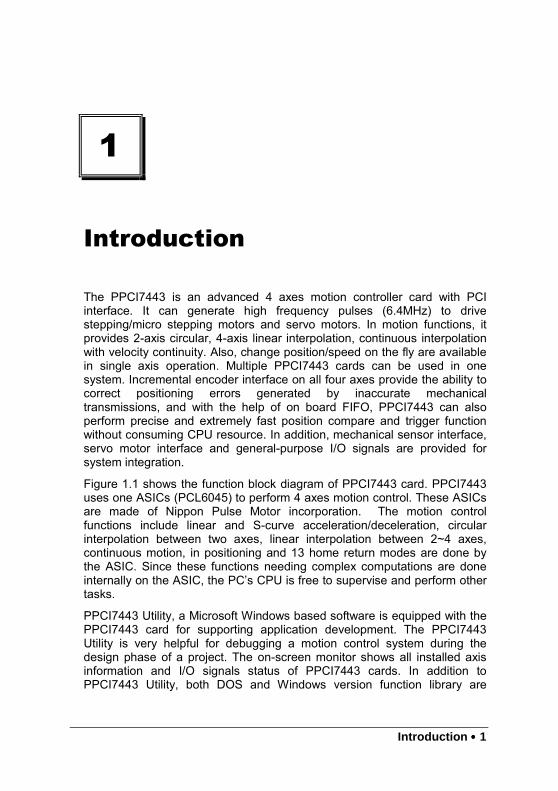
The PPCI7443 is an advanced 4 axes motion controller card with PCIinterface. It can generate high frequency pulses (6.4MHz) to drivestepping/micro stepping motors and servo motors. In motion functions, itprovides 2-axis circular, 4-axis linear interpolation, continuous interpolationwith velocity continuity. Also, change position/speed on the fly are availablein single axis operation. Multiple PPCI7443 cards can be used in onesystem. Incremental encoder interface on all four axes provide the ability tocorrect positioning errors generated by inaccurate mechanicaltransmissions, and with the help of on board FIFO, PPCI7443 can alsoperform precise and extremely fast position compare and trigger functionwithout consuming CPU resource. In addition, mechanical sensor interface,servo motor interface and general-purpose I/O signals are provided forsystem integration.
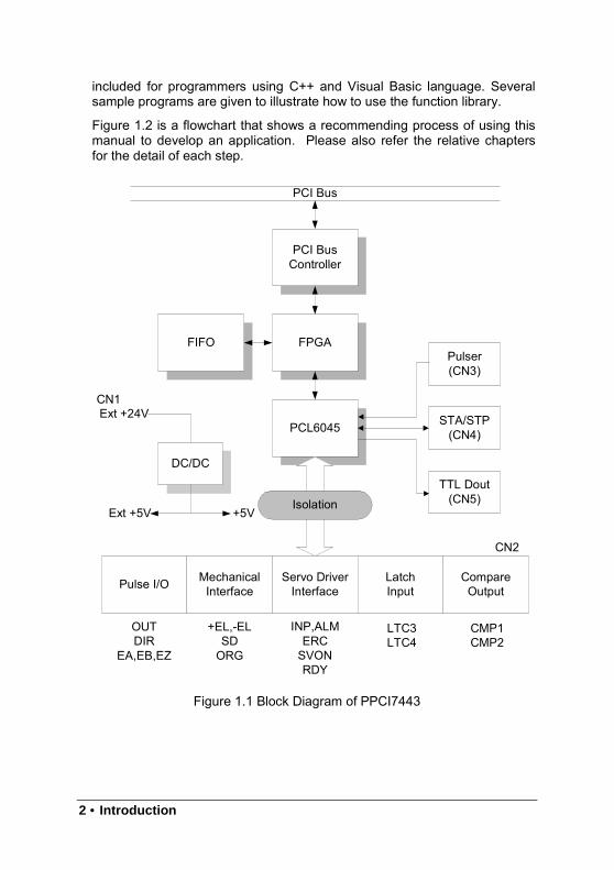
Figure 1.1 shows the function block diagram of PPCI7443 card. PPCI7443uses one ASICs (PCL6045) to perform 4 axes motion control. These ASICsare made of Nippon Pulse Motor incorporation. The motion controlfunctions include linear and S-curve acceleration/deceleration, circularinterpolation between two axes, linear interpolation between 2~4 axes,continuous motion, in positioning and 13 home return modes are done bythe ASIC. Since these functions needing complex computations are doneinternally on the ASIC, the PC’s CPU is free to supervise and perform othertasks.
PPCI7443 Utility, a Microsoft Windows based software is equipped with thePPCI7443 card for supporting application development. The PPCI7443Utility is very helpful for debugging a motion control system during thedesign phase of a project. The on-screen monitor shows all installed axisinformation and I/O signals status of PPCI7443 cards. In addition toPPCI7443 Utility, both DOS and Windows version function library are
2 • Introduction
included for programmers using C++ and Visual Basic language. Severalsample programs are given to illustrate how to use the function library.
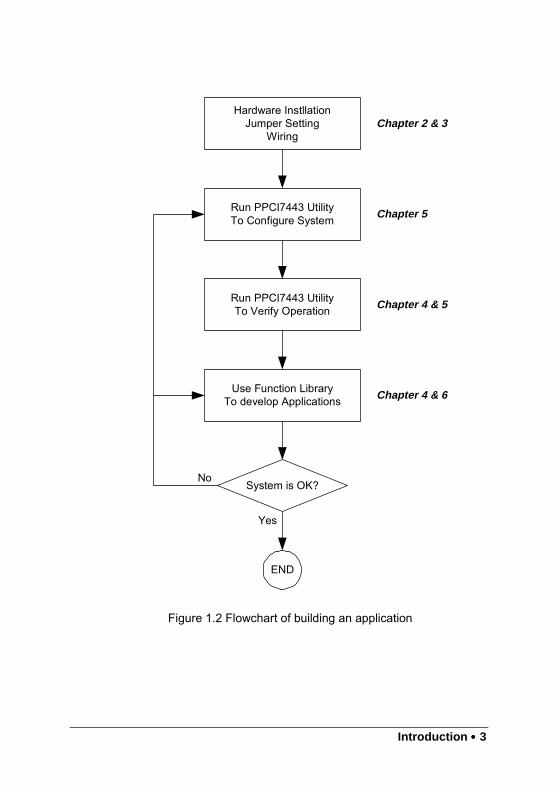
Figure 1.2 is a flowchart that shows a recommending process of using thismanual to develop an application. Please also refer the relative chaptersfor the detail of each step.
Figure 1.1 Block Diagram of PPCI7443
PCI Bus
PCI BusController
FPGAFIFO
PCL6045
Pulser(CN3)
STA/STP(CN4)
TTL Dout(CN5)
Pulse I/O MechanicalInterface
Servo DriverInterface
LatchInput
CompareOutput
Isolation
OUTDIR
EA,EB,EZ
+EL,-ELSDORG
INP,ALMERCSVONRDY
CMP1CMP2
LTC3LTC4
DC/DC
Ext +24V
+5VExt +5V
CN2
CN1
Introduction •••• 3
Figure 1.2 Flowchart of building an application
Hardware InstllationJumper Setting
Wiring
Run PPCI7443 UtilityTo Configure System
Run PPCI7443 UtilityTo Verify Operation
Use Function LibraryTo develop Applications
System is OK?
END
Chapter 2 & 3
Chapter 5
Chapter 4 & 5
Chapter 4 & 6
No
Yes
4 • Introduction
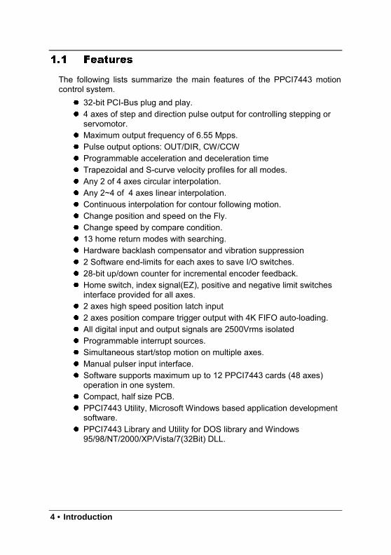
1.1 Features
The following lists summarize the main features of the PPCI7443 motioncontrol system.
32-bit PCI-Bus plug and play. 4 axes of step and direction pulse output for controlling stepping or
servomotor. Maximum output frequency of 6.55 Mpps. Pulse output options: OUT/DIR, CW/CCW Programmable acceleration and deceleration time Trapezoidal and S-curve velocity profiles for all modes. Any 2 of 4 axes circular interpolation. Any 2~4 of 4 axes linear interpolation. Continuous interpolation for contour following motion. Change position and speed on the Fly. Change speed by compare condition. 13 home return modes with searching. Hardware backlash compensator and vibration suppression 2 Software end-limits for each axes to save I/O switches. 28-bit up/down counter for incremental encoder feedback. Home switch, index signal(EZ), positive and negative limit switches
interface provided for all axes. 2 axes high speed position latch input 2 axes position compare trigger output with 4K FIFO auto-loading. All digital input and output signals are 2500Vrms isolated Programmable interrupt sources. Simultaneous start/stop motion on multiple axes. Manual pulser input interface. Software supports maximum up to 12 PPCI7443 cards (48 axes)
operation in one system. Compact, half size PCB. PPCI7443 Utility, Microsoft Windows based application development
software. PPCI7443 Library and Utility for DOS library and Windows
95/98/NT/2000/XP/Vista/7(32Bit) DLL.
Introduction •••• 5
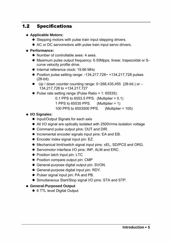
1.2 Specifications
Applicable Motors: Stepping motors with pulse train input stepping drivers. AC or DC servomotors with pulse train input servo drivers.
Performance: Number of controllable axes: 4 axes. Maximum pulse output frequency: 6.55Mpps, linear, trapezoidal or S-
curve velocity profile drive. Internal reference clock: 19.66 MHz Position pulse setting range: -134,217,728~ +134,217,728 pulses
(28-bit). Up / down counter counting range: 0~268,435,455 (28-bit.) or –
134,217,728 to +134,217,727 Pulse rate setting range (Pulse Ratio = 1: 65535):
0.1 PPS to 6553.5 PPS. (Multiplier = 0.1)1 PPS to 65535 PPS. (Multiplier = 1)100 PPS to 6553500 PPS. (Multiplier = 100)
I/O Signales: Input/Output Signals for each axis All I/O signal are optically isolated with 2500Vrms isolation voltage Command pulse output pins: OUT and DIR. Incremental encoder signals input pins: EA and EB. Encoder index signal input pin: EZ. Mechanical limit/switch signal input pins: ±EL, SD/PCS and ORG. Servomotor interface I/O pins: INP, ALM and ERC. Position latch input pin: LTC Position compare output pin: CMP General-purpose digital output pin: SVON. General-purpose digital input pin: RDY. Pulser signal input pin: PA and PB. Simultaneous Start/Stop signal I/O pins: STA and STP.
General-Purposed Output 6 TTL level Digital Output

6 • Introduction
General Specifications Connectors: 100-pin SCSI-type connector Operating Temperature: 0° C ~ 50° C Storage Temperature: -20° C ~ 80° C Humidity: 5 ~ 85%, non-condensing Power Consumption:
Slot power supply(input): +5V DC ±5%, 900mA max. External power supply(input): +24V DC ±5%, 500mA max. External power supply(output): +5V DC ±5%, 500mA, max.
Dimension: 185mm(L) X 98.4mm(H)
1.3 Software Supporting
1.3.1 Programming Library
For the customers who are writing their own programs, we provide MS-DOSBorland C/C++ (Version: 3.1) programming library and Windows-95/98/NT/2000/XP/Vista/7(32bit) DLL for PPCI7443. These function librariesare shipped with the board.
1.3.2 PPCI7443 Utility
A Windows-based Utility for users to setup cards, motors and system. It canhelp users to debug their hardware and software. It also can let users tosetting the I/O logic parameters which can be loaded in their own program.This product is bundled with this card.
Refer to Chapter 5 for details.

Installation • 7
2
Installation
This chapter describes how to install the PPCI7443. Please follow thesesteps below to install the PPCI7443.
Check what you have (section 2.1) Check the PCB (section 2.2) Install the hardware (section 2.3) Install the software driver (section 2.4) Understanding the I/O signal connections (chapter 3) and their
operation (chapter 4) Understanding the connectors’ pin assignments (the rest of the
sections) and wiring the connections
2.1 What You Have
In addition to this User’s Guide, the package includes the following items: PPCI7443: advanced 4 Axes Servo / Stepper Motion Control Card Install CD-ROM +24V power input cable (for CN1) accessory. Input/output signal cable(for CN2) accessory. Manual pulser input cable(for CN3) accessory. simultaneously start/stop signals for multiple axes cable(for CN4)
accessory. general-purposed TTL output signals cable(for CN5) accessory.
If any of these items are missing or damaged, contact the dealer fromwhom you purchased the product. Save the shipping materials and cartonin case you want to ship or store the product in the future.
8 • Installation
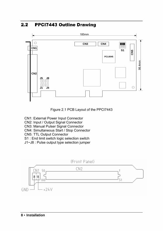
2.2 PPCI7443 Outline Drawing
Figure 2.1 PCB Layout of the PPCI7443
Figure 2.1 PCB Layout of the PPCI7443
CN1: External Power Input ConnectorCN2: Input / Output Signal ConnectorCN3: Manual Pulser Signal ConnectorCN4: Simultaneous Start / Stop ConnectorCN5: TTL Output ConnectorS1 : End limit switch logic selection switchJ1~J8 : Pulse output type selection jumper
CN1
CN2
J1 J4
J5 J8
PCL6045
CN3 CN4
CN
5S1
185mm
98.4mm

Installation • 9
2.3 Hardware Installation
2.3.1 Hardware configuration
PPCI7443 has plug and play PCI controller on board. The memory usage(I/O port locations) of the PCI card is assigned by system BIOS. Theaddress assignment is done on a board-by-board basis for all PCI cards inthe system.
2.3.2 PCI slot selection
Your computer will probably have both PCI and ISA slots. Do not force thePCI card into a PC/AT slot. The PPCI7443 can be used in any PCI slot.
2.3.3 Installation Procedures
1. Read through this manual, and setup the jumper according to yourapplication
2. Turn off your computer, Turn off all accessories (printer, modem, monitor,etc.) connected to computer.
Remove the cover from your computer.
3. Select a 32-bit PCI expansion slot. PCI slots are shorter than ISA or EISAslots and are usually white or ivory.
4. Before handling the PPCI7443, discharge any static buildup on your bodyby touching the metal case of the computer. Hold the edge and do nottouch the components.
5. Position the board into the PCI slot you selected.
6. Secure the card in place at the rear panel of the system unit using screwremoved from the slot.
2.3.4 Trouble shooting:
If your system won’t boot or if you experience erratic operation with yourPCI board in place, it’s likely caused by an interrupt conflict (perhapsbecause you incorrectly described the ISA setup). In general, the solution,once you determine it is not a simple oversight, is to consult the BIOSdocumentation that come with your system.

10 • Installation
2.4 Software Driver Installation
Step 1: Run setup from install CD
Step 2: Follow the procedures of installer.
Step 3: After setup completion, restart windows.
2.5 CN1 Pin Assignments: External Power Input
CN1 Pin No Name Description1 EXGND Grounds of the external power.2 EX+24V External power supply of +24V DC ± 5%
Notes:
1. CN1 is a plug-in terminal board with no screw.
2. Be sure to use the external power supply. The +24V DC is used byexternal input/output signal circuit. The power circuit is configured asfollows.
3. Wires for connection to CN1Solid wire: ϕ 0.32mm to ϕ 0.65mm (AWG28 to AWG22)Twisted wire:0.08mm2 to 0.32mm2 (AWG28 to AWG22)Naked wire length:10mm standard
The following diagram shows the external power supply system of thePPCI7443. The external +24V power must be provided, an on-boardregulator generates +5V for both internal and external usage.
Note: Please don’t use the +5V power source to drive too manydevices, especially stepping drivers or external encoders. The drivingcapacity would be not enough.
DC/DC
Externaal
Power
Supply
Isolation
(Bus Power)
+5VGND
I/O SIGNALS
(External Power)
EX+24V
EXGND
EX+5V
I/OSIGNALS
(OUTPUT)
Internal
Power
Supply
fromPC
IBUS

Installation • 11
2.6 CN2 Pin Assignments: Main connector
The CN2 is the major connector for the motion control I/O signals.No. Name I/O Function(axis/) No. Name I/O Function(axis/)1 VPP O +5V power supply output 51 VPP O +5V power supply output2 GND Ext. power ground 52 GND Ext. power ground3 OUT1+ O Pulse signal (+), 53 OUT3+ O Pulse signal (+), 4 OUT1- O Pulse signal (-), 54 OUT3- O Pulse signal (-),5 DIR1+ O Dir. signal (+), 55 DIR3+ O Dir. signal (+), 6 DIR1- O Dir. signal (-), 56 DIR3- O Dir. signal (-), 7 SVON1 O Multi-purpose signal, 57 SVON3 O Multi-purpose signal, 8 ERC1 O Dev. ctr, clr. signal, 58 ERC3 O Dev. ctr, clr. signal, 9 ALM1 I Alarm signal, 59 ALM3 I Alarm signal, 10 INP1 I In-position signal, 60 INP3 I In-position signal, 11 RDY1 I Multi-purpose signal, 61 RDY3 I Multi-purpose signal, 12 GND Ext. power ground 62 EXGND Ext. power ground13 EA1+ I Encoder A-phase (+), 63 EA3+ I Encoder A-phase (+), 14 EA1- I Encoder A-phase (-), 64 EA3- I Encoder A-phase (-),15 EB1+ I Encoder B-phase (+), 65 EB3+ I Encoder B-phase (+),16 EB1- I Encoder B-phase (-), 66 EB3- I Encoder B-phase (-),17 EZ1+ I Encoder Z-phase (+), 67 EZ3+ I Encoder Z-phase (+),18 EZ1- I Encoder Z-phase (-), 68 EZ3- I Encoder Z-phase (-),19 VPP O +5V power supply output 69 VPP O +5V power supply output20 GND Ext. power ground 70 GND Ext. power ground21 OUT2+ O Pulse signal (+), 71 OUT4+ O Pulse signal (+),22 OUT2- O Pulse signal (-), 72 OUT4- O Pulse signal (-),23 DIR2+ O Dir. signal (+), 73 DIR4+ O Dir. signal (+),24 DIR2- O Dir. signal (-), 74 DIR4- O Dir. signal (-),25 SVON2 O Multi-purpose signal, 75 SVON4 O Multi-purpose signal, 26 ERC2 O Dev. ctr, clr. signal, 76 ERC4 O Dev. ctr, clr. signal, 27 ALM2 I Alarm signal, 77 ALM4 I Alarm signal, 28 INP2 I In-position signal, 78 INP4 I In-position signal, 29 RDY2 I Multi-purpose signal, 79 RDY4 I Multi-purpose signal, 30 GND Ext. power ground 80 GND Ext. power ground31 EA2+ I Encoder A-phase (+), 81 EA4+ I Encoder A-phase (+), 32 EA2- I Encoder A-phase (-), 82 EA4- I Encoder A-phase (-), 33 EB2+ I Encoder B-phase (+), 83 EB4+ I Encoder B-phase (+), 34 EB2- I Encoder B-phase (-), 84 EB4- I Encoder B-phase (-), 35 EZ2+ I Encoder Z-phase (+), 85 EZ4+ I Encoder Z-phase (+), 36 EZ2- I Encoder Z-phase (-), 86 EZ4- I Encoder Z-phase (-), 37 PEL1 I End limit signal (+), 87 PEL3 I End limit signal (+), 38 MEL1 I End limit signal (-), 88 MEL3 I End limit signal (-), 39 CMP1 O Position compare output 89 LTC3 I Position latch input 40 SD/PCS1 I Ramp-down signal 90 SD/PCS3 I Ramp-down signal 41 ORG1 I Origin signal, 91 ORG3 I Origin signal, 42 GND Ext. power ground 92 GND Ext. power ground43 PEL2 I End limit signal (+), 93 PEL4 I End limit signal (+), 44 MEL2 I End limit signal (-), 94 MEL4 I End limit signal (-), 45 CMP2 O Position compare output 95 LTC4 I Position latch input, 46 SD/PCS2 I Ramp-down signal 96 SD/PCS4 I Ramp-down signal 47 ORG2 I Origin signal, 97 ORG4 I Origin signal, 48 GND Ext. power ground 98 GND Ext. power ground49 GND Ext. power ground 99 E_24V 0 Ext. power supply, +24V50 GND Ext. power ground 100 E_24V 0 Ext. power supply, +24V
12 • Installation
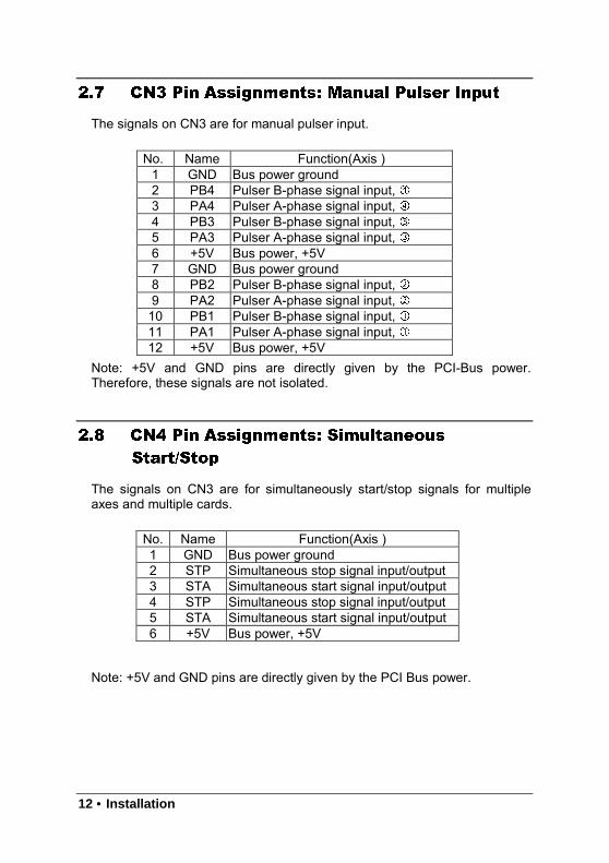
2.7 CN3 Pin Assignments: Manual Pulser Input
The signals on CN3 are for manual pulser input.
No. Name Function(Axis )1 GND Bus power ground2 PB4 Pulser B-phase signal input, 3 PA4 Pulser A-phase signal input, 4 PB3 Pulser B-phase signal input, 5 PA3 Pulser A-phase signal input, 6 +5V Bus power, +5V7 GND Bus power ground8 PB2 Pulser B-phase signal input, 9 PA2 Pulser A-phase signal input, 10 PB1 Pulser B-phase signal input, 11 PA1 Pulser A-phase signal input, 12 +5V Bus power, +5V
Note: +5V and GND pins are directly given by the PCI-Bus power.Therefore, these signals are not isolated.
2.8 CN4 Pin Assignments: Simultaneous
Start/Stop
The signals on CN3 are for simultaneously start/stop signals for multipleaxes and multiple cards.
No. Name Function(Axis )1 GND Bus power ground2 STP Simultaneous stop signal input/output3 STA Simultaneous start signal input/output4 STP Simultaneous stop signal input/output5 STA Simultaneous start signal input/output6 +5V Bus power, +5V
Note: +5V and GND pins are directly given by the PCI Bus power.
Installation • 13
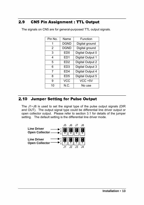
2.9 CN5 Pin Assignment : TTL Output
The signals on CN5 are for general-purposed TTL output signals.
2.10 Jumper Setting for Pulse Output
The J1~J8 is used to set the signal type of the pulse output signals (DIRand OUT). The output signal type could be differential line driver output oropen collector output. Please refer to section 3.1 for details of the jumpersetting. The default setting is the differential line driver mode.
Line DriverOpen Collector
Line DriverOpen Collector
Pin No. Name Function1 DGND Digital ground2 DGND Digital ground3 ED0 Digital Output 04 ED1 Digital Output 15 ED2 Digital Output 26 ED3 Digital Output 37 ED4 Digital Output 48 ED5 Digital Output 59 VCC VCC +5V10 N.C. No use
123
J5 J6 J7 J8
J1 J2 J3 J4
123
14 • Installation
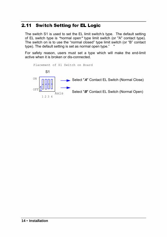
2.11 Switch Setting for EL Logic
The switch S1 is used to set the EL limit switch’s type. The default settingof EL switch type is “ normal open” type limit switch (or "A" contact type).The switch on is to use the “normal closed” type limit switch (or “B” contacttype). The default setting is set as normal open type.” "
For safety reason, users must set a type which will make the end-limitactive when it is broken or dis-connected.
Placement of S1 Switch on Board
Axis4321
OFF
ON
S1
Select "B" Contact EL Switch (Normal Open)
Select "A" Contact EL Switch (Normal Close)
Single Connections • 15
3
Signal Connections
The signal connections of all the I/O signals are described in this chapter.Please refer the contents of this chapter before wiring the cable betweenthe PPCI7443 and the motor drivers.
This chapter contains the following sections:Section 3.1 Pulse output signals OUT and DIRSection 3.2 Encoder feedback signals EA, EB and EZSection 3.3 Origin signal ORGSection 3.4 End-Limit signals PEL and MELSection 3.5 Ramping-down & PCSSection 3.6 In-position signal INPSection 3.7 Alarm signal ALMSection 3.8 Deviation counter clear signal ERCSection 3.9 General-purpose signal SVONSection 3.10 General-purpose signal RDYSection 3.11 Position compare output pin: CMPSection 3.12 Position latch input pin: LTCSection 3.13 Pulser input signals PA and PBSection 3.14 Simultaneous start/stop signals STA and STPSection 3.15 General-purposed TTL Output
16 • Single Connections
3.1 Pulse Output Signals OUT and DIR
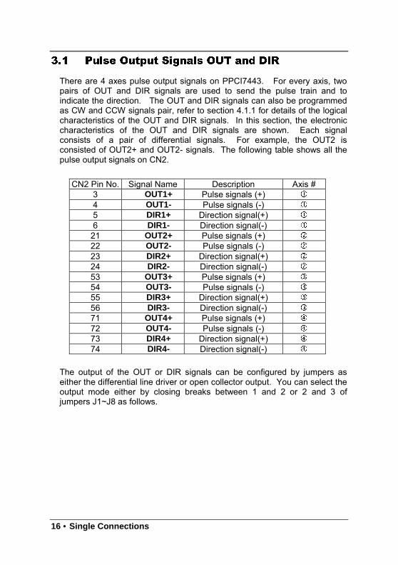
There are 4 axes pulse output signals on PPCI7443. For every axis, twopairs of OUT and DIR signals are used to send the pulse train and toindicate the direction. The OUT and DIR signals can also be programmedas CW and CCW signals pair, refer to section 4.1.1 for details of the logicalcharacteristics of the OUT and DIR signals. In this section, the electroniccharacteristics of the OUT and DIR signals are shown. Each signalconsists of a pair of differential signals. For example, the OUT2 isconsisted of OUT2+ and OUT2- signals. The following table shows all thepulse output signals on CN2.
CN2 Pin No. Signal Name Description Axis #3 OUT1+ Pulse signals (+)
4 OUT1- Pulse signals (-)
5 DIR1+ Direction signal(+)
6 DIR1- Direction signal(-)
21 OUT2+ Pulse signals (+)
22 OUT2- Pulse signals (-)
23 DIR2+ Direction signal(+)
24 DIR2- Direction signal(-)
53 OUT3+ Pulse signals (+)
54 OUT3- Pulse signals (-)
55 DIR3+ Direction signal(+)
56 DIR3- Direction signal(-)
71 OUT4+ Pulse signals (+)
72 OUT4- Pulse signals (-)
73 DIR4+ Direction signal(+)
74 DIR4- Direction signal(-)
The output of the OUT or DIR signals can be configured by jumpers aseither the differential line driver or open collector output. You can select theoutput mode either by closing breaks between 1 and 2 or 2 and 3 ofjumpers J1~J8 as follows.
Single Connections • 17
OutputSignal
For differential line driveroutput, close a breakbetween 1 and 2 of
For open collectoroutput, close a breakbetween 2 and 3 of:
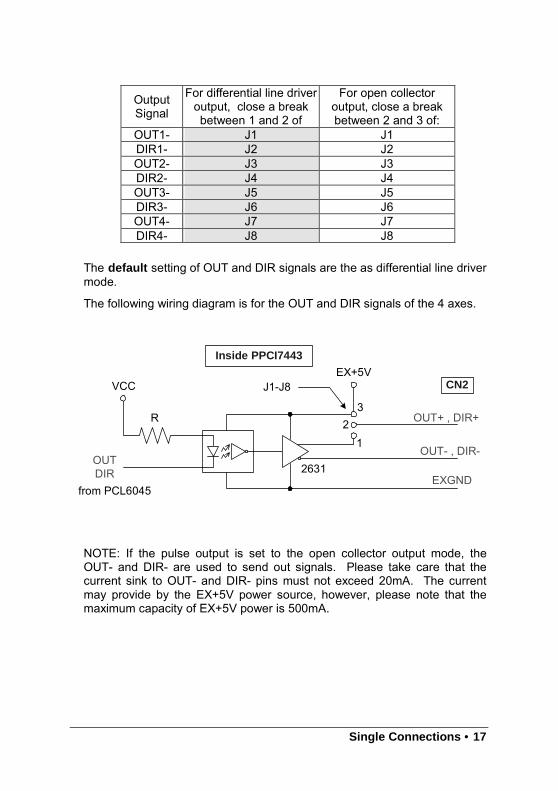
OUT1- J1 J1DIR1- J2 J2OUT2- J3 J3DIR2- J4 J4OUT3- J5 J5DIR3- J6 J6OUT4- J7 J7DIR4- J8 J8
The default setting of OUT and DIR signals are the as differential line drivermode.
The following wiring diagram is for the OUT and DIR signals of the 4 axes.
OUT+ , DIR+
EXGNDfrom PCL6045
R
VCC
OUTDIR
EX+5V
32
1
J1-J8
OUT- , DIR-2631
CN2
Inside PPCI7443
NOTE: If the pulse output is set to the open collector output mode, theOUT- and DIR- are used to send out signals. Please take care that thecurrent sink to OUT- and DIR- pins must not exceed 20mA. The currentmay provide by the EX+5V power source, however, please note that themaximum capacity of EX+5V power is 500mA.
18 • Single Connections
3.2 Encoder Feedback Signals EA, EB and EZ
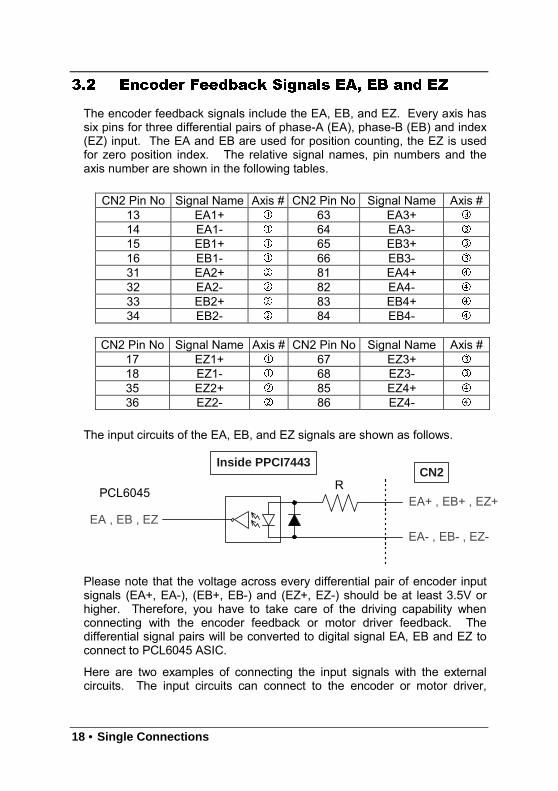
The encoder feedback signals include the EA, EB, and EZ. Every axis hassix pins for three differential pairs of phase-A (EA), phase-B (EB) and index(EZ) input. The EA and EB are used for position counting, the EZ is usedfor zero position index. The relative signal names, pin numbers and theaxis number are shown in the following tables.
CN2 Pin No Signal Name Axis # CN2 Pin No Signal Name Axis #13 EA1+ 63 EA3+
14 EA1- 64 EA3-
15 EB1+ 65 EB3+
16 EB1- 66 EB3-
31 EA2+ 81 EA4+
32 EA2- 82 EA4-
33 EB2+ 83 EB4+
34 EB2- 84 EB4-
CN2 Pin No Signal Name Axis # CN2 Pin No Signal Name Axis #17 EZ1+ 67 EZ3+
18 EZ1- 68 EZ3-
35 EZ2+ 85 EZ4+
36 EZ2- 86 EZ4-
The input circuits of the EA, EB, and EZ signals are shown as follows.
EA+ , EB+ , EZ+PCL6045 R
CN2Inside PPCI7443
EA- , EB- , EZ-EA , EB , EZ
Please note that the voltage across every differential pair of encoder inputsignals (EA+, EA-), (EB+, EB-) and (EZ+, EZ-) should be at least 3.5V orhigher. Therefore, you have to take care of the driving capability whenconnecting with the encoder feedback or motor driver feedback. Thedifferential signal pairs will be converted to digital signal EA, EB and EZ toconnect to PCL6045 ASIC.
Here are two examples of connecting the input signals with the externalcircuits. The input circuits can connect to the encoder or motor driver,

Single Connections • 19
which are equipped with: (1) differential line driver or (2) open collectoroutput.
20 • Single Connections
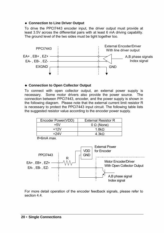
Connection to Line Driver Output
To drive the PPCI7443 encoder input, the driver output must provide atleast 3.5V across the differential pairs with at least 6 mA driving capability.The ground level of the two sides must be tight together too.
A,B phase signalsIndex signal
EXGND GNDEA- , EB- , EZ-
EA+ , EB+ , EZ+
PPCI7443External Encoder/DriverWith line driver output
Connection to Open Collector Output
To connect with open collector output, an external power supply isnecessary. Some motor drivers also provide the power source. Theconnection between PPCI7443, encoder, and the power supply is shown inthe following diagram. Please note that the external current limit resistor Ris necessary to protect the PPCI7443 input circuit. The following table liststhe suggested resistor value according to the encoder power supply.
Encoder Power(VDD) External Resistor R+5V 0 Ω (None)+12V 1.8kΩ+24V 4.3kΩ
If=6mA max.
A,B phase signalIndex signal
EA- , EB- , EZ-EA+ , EB+ , EZ+
PPCI7443
Motor Encoder/DriverWith Open Collector Output
VDDGND
External Powerfor Encoder
R
For more detail operation of the encoder feedback signals, please refer tosection 4.4.
Single Connections • 21
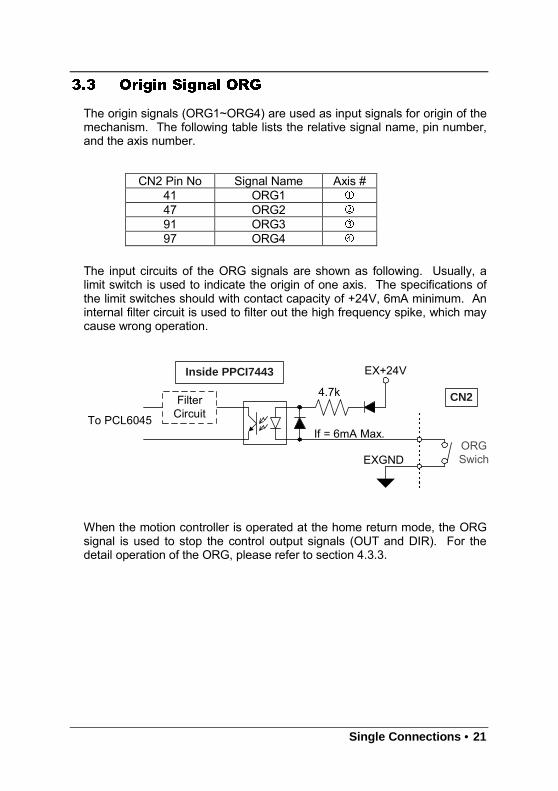
3.3 Origin Signal ORG
The origin signals (ORG1~ORG4) are used as input signals for origin of themechanism. The following table lists the relative signal name, pin number,and the axis number.
CN2 Pin No Signal Name Axis #41 ORG1
47 ORG2
91 ORG3
97 ORG4
The input circuits of the ORG signals are shown as following. Usually, alimit switch is used to indicate the origin of one axis. The specifications ofthe limit switches should with contact capacity of +24V, 6mA minimum. Aninternal filter circuit is used to filter out the high frequency spike, which maycause wrong operation.
To PCL6045
4.7k CN2
Inside PPCI7443
FilterCircuit
EX+24V
If = 6mA Max.ORGSwichEXGND
When the motion controller is operated at the home return mode, the ORGsignal is used to stop the control output signals (OUT and DIR). For thedetail operation of the ORG, please refer to section 4.3.3.
22 • Single Connections
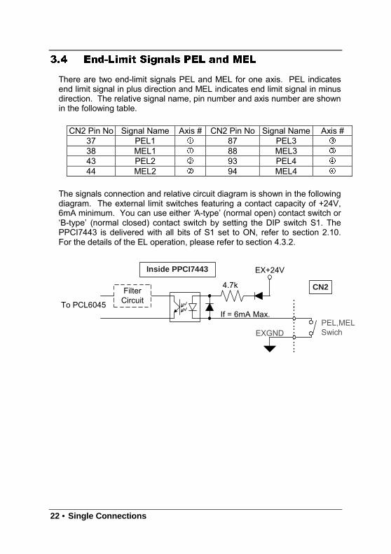
3.4 End-Limit Signals PEL and MEL
There are two end-limit signals PEL and MEL for one axis. PEL indicatesend limit signal in plus direction and MEL indicates end limit signal in minusdirection. The relative signal name, pin number and axis number are shownin the following table.
CN2 Pin No Signal Name Axis # CN2 Pin No Signal Name Axis #37 PEL1 87 PEL3
38 MEL1 88 MEL3
43 PEL2 93 PEL4
44 MEL2 94 MEL4
The signals connection and relative circuit diagram is shown in the followingdiagram. The external limit switches featuring a contact capacity of +24V,6mA minimum. You can use either ‘A-type’ (normal open) contact switch or‘B-type’ (normal closed) contact switch by setting the DIP switch S1. ThePPCI7443 is delivered with all bits of S1 set to ON, refer to section 2.10.For the details of the EL operation, please refer to section 4.3.2.
To PCL6045
4.7k CN2
Inside PPCI7443
FilterCircuit
EX+24V
If = 6mA Max.PEL,MELSwichEXGND
Single Connections • 23
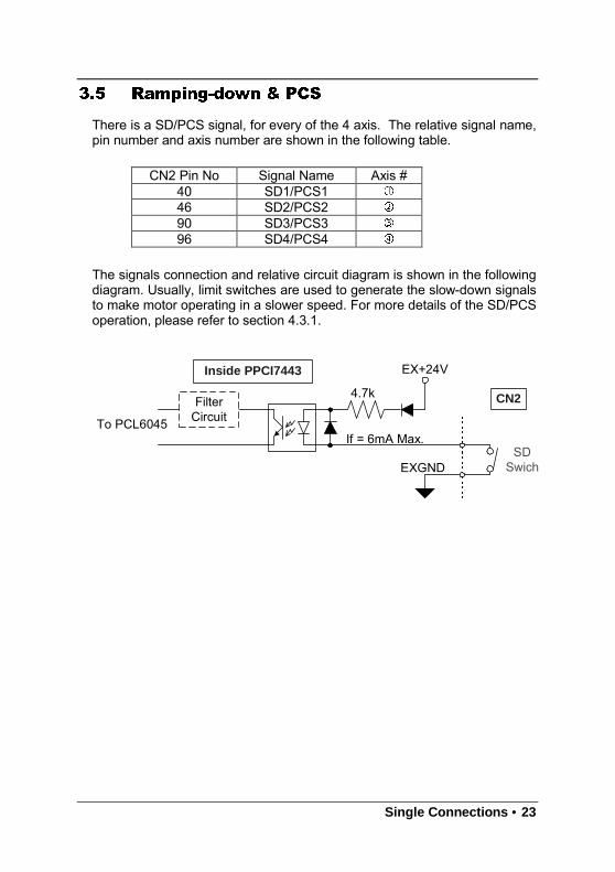
3.5 Ramping-down & PCS
There is a SD/PCS signal, for every of the 4 axis. The relative signal name,pin number and axis number are shown in the following table.
CN2 Pin No Signal Name Axis #40 SD1/PCS1
46 SD2/PCS2
90 SD3/PCS3
96 SD4/PCS4
The signals connection and relative circuit diagram is shown in the followingdiagram. Usually, limit switches are used to generate the slow-down signalsto make motor operating in a slower speed. For more details of the SD/PCSoperation, please refer to section 4.3.1.
To PCL6045
4.7k CN2
Inside PPCI7443
FilterCircuit
EX+24V
If = 6mA Max.SD
SwichEXGND
24 • Single Connections
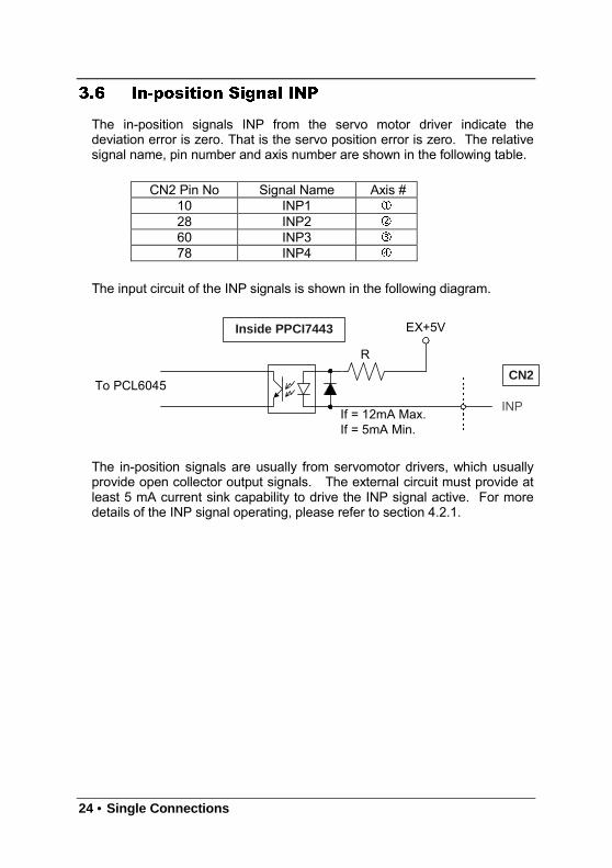
3.6 In-position Signal INP
The in-position signals INP from the servo motor driver indicate thedeviation error is zero. That is the servo position error is zero. The relativesignal name, pin number and axis number are shown in the following table.
CN2 Pin No Signal Name Axis #10 INP1
28 INP2
60 INP3
78 INP4
The input circuit of the INP signals is shown in the following diagram.
To PCL6045
RCN2
Inside PPCI7443 EX+5V
If = 12mA Max.If = 5mA Min.
INP
The in-position signals are usually from servomotor drivers, which usuallyprovide open collector output signals. The external circuit must provide atleast 5 mA current sink capability to drive the INP signal active. For moredetails of the INP signal operating, please refer to section 4.2.1.
Single Connections • 25
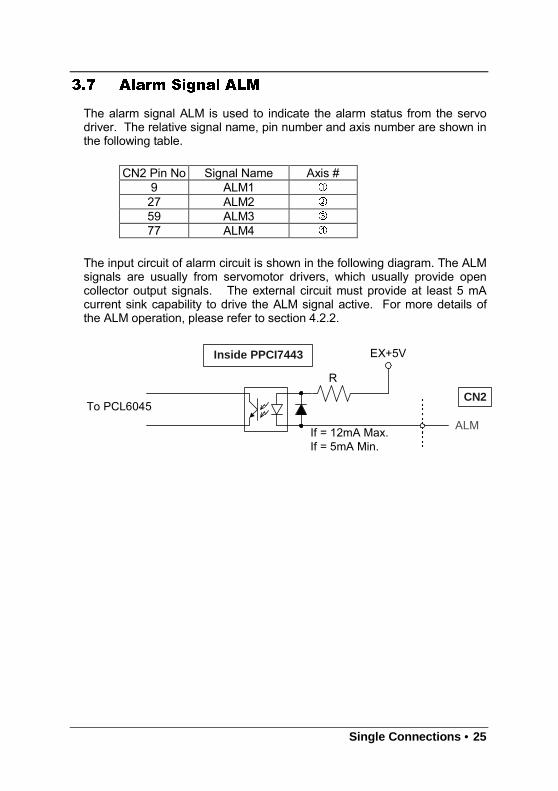
3.7 Alarm Signal ALM
The alarm signal ALM is used to indicate the alarm status from the servodriver. The relative signal name, pin number and axis number are shown inthe following table.
CN2 Pin No Signal Name Axis #9 ALM1
27 ALM2
59 ALM3
77 ALM4
The input circuit of alarm circuit is shown in the following diagram. The ALMsignals are usually from servomotor drivers, which usually provide opencollector output signals. The external circuit must provide at least 5 mAcurrent sink capability to drive the ALM signal active. For more details ofthe ALM operation, please refer to section 4.2.2.
To PCL6045
RCN2
Inside PPCI7443 EX+5V
If = 12mA Max.If = 5mA Min.
ALM
26 • Single Connections
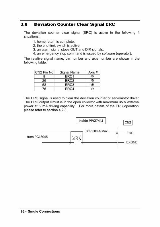
3.8 Deviation Counter Clear Signal ERC
The deviation counter clear signal (ERC) is active in the following 4situations:
1. home return is complete;2. the end-limit switch is active;3. an alarm signal stops OUT and DIR signals;4. an emergency stop command is issued by software (operator).
The relative signal name, pin number and axis number are shown in thefollowing table.
CN2 Pin No Signal Name Axis #8 ERC1
26 ERC2
58 ERC3
76 ERC4
The ERC signal is used to clear the deviation counter of servomotor driver.The ERC output circuit is in the open collector with maximum 35 V externalpower at 50mA driving capability. For more details of the ERC operation,please refer to section 4.2.3.
from PCL6045
CN2Inside PPCI7443
35V 50mA Max.
EXGND
ERC
Single Connections • 27
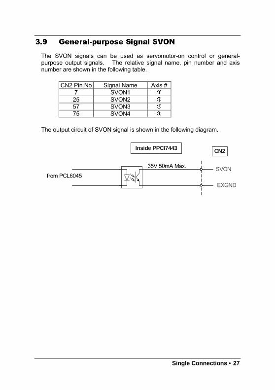
3.9 General-purpose Signal SVON
The SVON signals can be used as servomotor-on control or general-purpose output signals. The relative signal name, pin number and axisnumber are shown in the following table.
CN2 Pin No Signal Name Axis #7 SVON1
25 SVON2
57 SVON3
75 SVON4
The output circuit of SVON signal is shown in the following diagram.
from PCL6045
CN2Inside PPCI7443
35V 50mA Max.
EXGND
SVON
28 • Single Connections
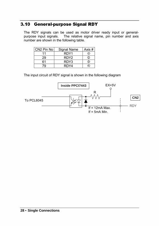
3.10 General-purpose Signal RDY
The RDY signals can be used as motor driver ready input or general-purpose input signals. The relative signal name, pin number and axisnumber are shown in the following table.
CN2 Pin No Signal Name Axis #11 RDY1
29 RDY2
61 RDY3
79 RDY4
The input circuit of RDY signal is shown in the following diagram
To PCL6045
RCN2
Inside PPCI7443 EX+5V
If = 12mA Max.If = 5mA Min.
RDY
Single Connections • 29
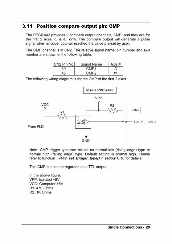
3.11 Position compare output pin: CMP
The PPCI7443 provides 2 compare output channels, CMP, and they are forthe first 2 axes, & , only. The compare output will generate a pulsesignal when encoder counter reached the value pre-set by user.
The CMP channel is in CN2. The relative signal name, pin number and axisnumber are shown in the following table.
CN2 Pin No Signal Name Axis #39 CMP1
45 CMP2
The following wiring diagram is for the CMP of the first 2 axes.
R2CN2
Inside PPCI7443
CMP1 , CMP2
VCC
From PLD
GND
VPP
R1
Note: CMP trigger type can be set as normal low (rising edge) type ornormal high (falling edge) type. Default setting is normal high. Pleaserefer to function _7443_set_trigger_type() in section 6.16 for details.
This CMP pin can be regarded as a TTL output.
In the above figure:VPP: Isolated +5VVCC: Computer +5VR1: 470 OhmsR2: 1K Ohms
30 • Single Connections
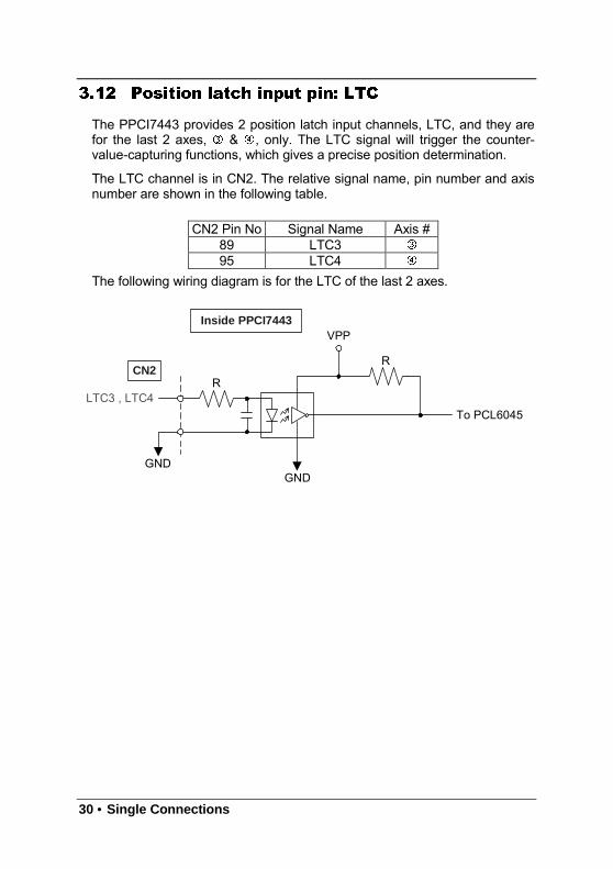
3.12 Position latch input pin: LTC
The PPCI7443 provides 2 position latch input channels, LTC, and they arefor the last 2 axes, & , only. The LTC signal will trigger the counter-value-capturing functions, which gives a precise position determination.
The LTC channel is in CN2. The relative signal name, pin number and axisnumber are shown in the following table.
CN2 Pin No Signal Name Axis #89 LTC3
95 LTC4
The following wiring diagram is for the LTC of the last 2 axes.
RCN2
Inside PPCI7443
To PCL6045LTC3 , LTC4
GND
VPP
R
GND
Single Connections • 31
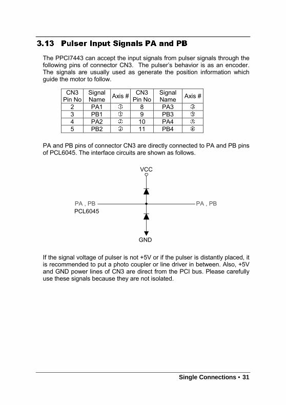
3.13 Pulser Input Signals PA and PB
The PPCI7443 can accept the input signals from pulser signals through thefollowing pins of connector CN3. The pulser’s behavior is as an encoder.The signals are usually used as generate the position information whichguide the motor to follow.
CN3Pin No
SignalName Axis # CN3
Pin NoSignalName Axis #
2 PA1 8 PA3
3 PB1 9 PB3
4 PA2 10 PA4
5 PB2 11 PB4
PA and PB pins of connector CN3 are directly connected to PA and PB pinsof PCL6045. The interface circuits are shown as follows.
VCC
GND
PA , PBPA , PBPCL6045
If the signal voltage of pulser is not +5V or if the pulser is distantly placed, itis recommended to put a photo coupler or line driver in between. Also, +5Vand GND power lines of CN3 are direct from the PCI bus. Please carefullyuse these signals because they are not isolated.
32 • Single Connections
3.14 Simultaneously Start/Stop Signals STA and
STP
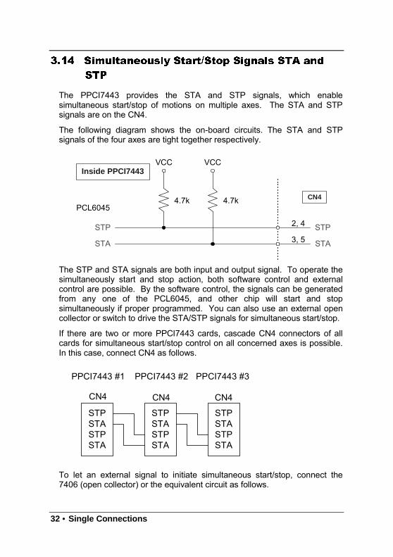
The PPCI7443 provides the STA and STP signals, which enablesimultaneous start/stop of motions on multiple axes. The STA and STPsignals are on the CN4.
The following diagram shows the on-board circuits. The STA and STPsignals of the four axes are tight together respectively.
4.7k 4.7k
2, 4 STP
STA
CN4
Inside PPCI7443
STP
STA
PCL6045
VCC VCC
3, 5
The STP and STA signals are both input and output signal. To operate thesimultaneously start and stop action, both software control and externalcontrol are possible. By the software control, the signals can be generatedfrom any one of the PCL6045, and other chip will start and stopsimultaneously if proper programmed. You can also use an external opencollector or switch to drive the STA/STP signals for simultaneous start/stop.
If there are two or more PPCI7443 cards, cascade CN4 connectors of allcards for simultaneous start/stop control on all concerned axes is possible.In this case, connect CN4 as follows.
STPSTASTPSTA
STPSTASTPSTA
STPSTASTPSTA
CN4 CN4 CN4
PPCI7443 #1 PPCI7443 #3PPCI7443 #2
To let an external signal to initiate simultaneous start/stop, connect the7406 (open collector) or the equivalent circuit as follows.
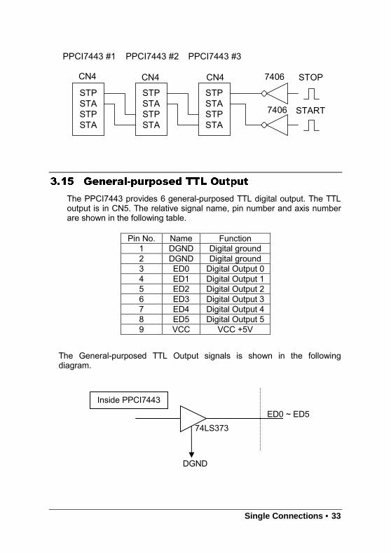
Single Connections • 33
STPSTASTPSTA
STPSTASTPSTA
STPSTASTPSTA
CN4 CN4 CN4
PPCI7443 #1 PPCI7443 #3PPCI7443 #2
7406
7406
STOP
START
3.15 General-purposed TTL Output
The PPCI7443 provides 6 general-purposed TTL digital output. The TTLoutput is in CN5. The relative signal name, pin number and axis numberare shown in the following table.
The General-purposed TTL Output signals is shown in the followingdiagram.
Pin No. Name Function1 DGND Digital ground2 DGND Digital ground3 ED0 Digital Output 04 ED1 Digital Output 15 ED2 Digital Output 26 ED3 Digital Output 37 ED4 Digital Output 48 ED5 Digital Output 59 VCC VCC +5V
Inside PPCI7443
DGND
74LS373ED0 ~ ED5

34 • Single Connections
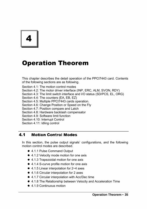
Operation Theorem • 35
4
Operation Theorem
This chapter describes the detail operation of the PPCI7443 card. Contentsof the following sections are as following.Section 4.1: The motion control modesSection 4.2: The motor driver interface (INP, ERC, ALM, SVON, RDY)Section 4.3: The limit switch interface and I/O status (SD/PCS, EL, ORG)Section 4.4: The counters (EA, EB, EZ)Section 4.5: Multiple PPCI7443 cards operation.Section 4.6: Change Position or Speed on the FlySection 4.7: Position compare and LatchSection 4.8: Hardware backlash compensatorSection 4.9: Software limit functionSection 4.10: Interrupt ControlSection 4.11: Idling control
4.1 Motion Control Modes
In this section, the pulse output signals’ configurations, and the followingmotion control modes are described. 4.1.1 Pulse Command Output 4.1.2 Velocity mode motion for one axis 4.1.3 Trapezoidal motion for one axis 4.1.4 S-curve profile motion for one axis 4.1.5 Linear interpolation for 2~4 axes 4.1.6 Circular interpolation for 2 axes 4.1.7 Circular interpolation with Acc/Dec time 4.1.8 The Relationship between Velocity and Acceleration Time 4.1.9 Continuous motion
36 • Operation Theorem
4.1.10 Home return mode for one axis 4.1.11 Manual pulser mode for one axis 4.1.12 Timer Mode 4.1.13 Pulser Interpolation
4.1.1 Pulse Command Output
The PPCI7443 uses pulse command to control the servo / stepper motorsvia the drivers. The pulse command consists of two signals: OUT and DIR.There are two command types: (1) single pulse output mode (OUT/DIR);and (2) dual pulse output mode (CW/CCW type pulse output). The softwarefunction: _7443_set_pls_outmode() is used to program the pulsecommand type. The modes vs. signal type of OUT and DIR pins are asfollowing table:
Mode Output of OUT pin Output of DIR pinDual pulse output
(CW/CCW)Pulse signal in plus(or CW) direction
Pulse signal in minus(or CCW) direction
Single pulse output(OUT/DIR) Pulse signal Direction signal (level)
The interface characteristics of these signals could be differential line driveror open collector output. Please refer to section 3.1 for the jumper settingof signal types.
Single Pulse Output Mode(OUT/DIR Mode)
In this mode, the OUT signal is for the command pulse (position or velocity)chain. The numbers of OUT pulse represent the relative “distance” or“position”, the frequency of the OUT pulse represents the command for“speed” or “velocity”. The DIR signal represents direction command of thepositive (+) or negative (-). This mode is the most common used mode.The following diagrams show the output waveform. It is possible to set thepolarity of pulse chain.
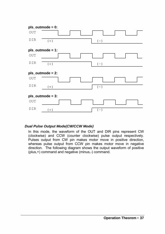
Operation Theorem • 37
pls_outmode = 0:
pls_outmode = 1:
pls_outmode = 2:
pls_outmode = 3:
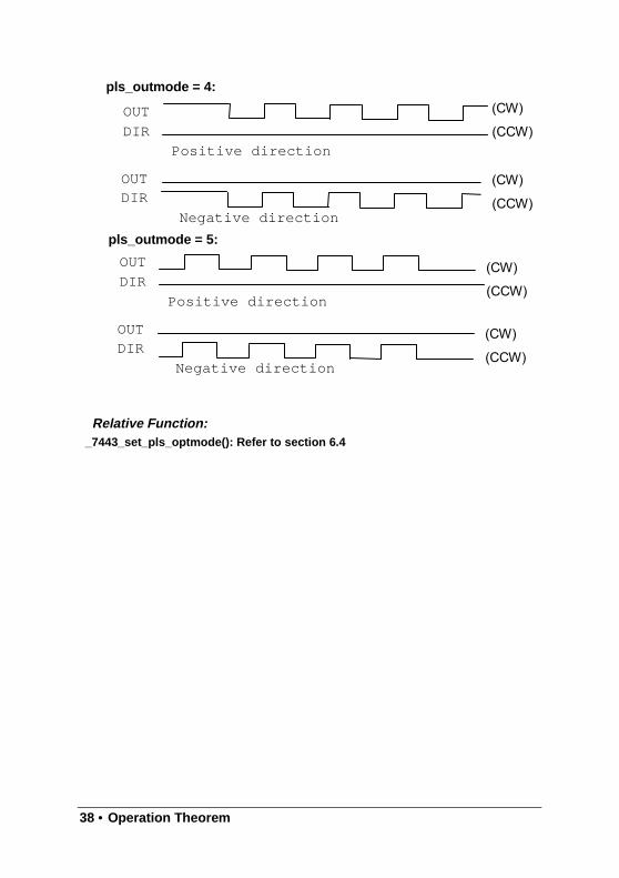
Dual Pulse Output Mode(CW/CCW Mode)In this mode, the waveform of the OUT and DIR pins represent CW(clockwise) and CCW (counter clockwise) pulse output respectively.Pulses output from CW pin makes motor move in positive direction,whereas pulse output from CCW pin makes motor move in negativedirection. The following diagram shows the output waveform of positive(plus,+) command and negative (minus,-) command.
OUT
DIR (+) (-)
OUT
DIR (+) (-)
OUT
DIR (+) (-)
OUT
DIR (+) (-)
38 • Operation Theorem
pls_outmode = 4:
pls_outmode = 5:
Relative Function:_7443_set_pls_optmode(): Refer to section 6.4
(CW)
OUTDIR
Negative direction
OUT
DIR
Positive direction
OUTDIR
Negative direction
OUT
DIR
Positive direction
(CCW)
(CW)
(CCW)
(CW)
(CCW)
(CW)
(CCW)
Operation Theorem • 39
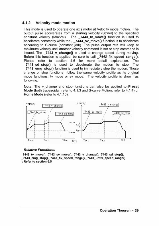
4.1.2 Velocity mode motion
This mode is used to operate one axis motor at Velocity mode motion. Theoutput pulse accelerates from a starting velocity (StrVel) to the specifiedconstant velocity (MaxVel). The _7443_tv_move() function is used toaccelerate constantly while the , _7443_sv_move() function is to accelerateaccording to S-curve (constant jerk). The pulse output rate will keep atmaximum velocity until another velocity command is set or stop command isissued. The _7443_v_change() is used to change speed during moving.Before this function is applied, be sure to call _7443_fix_speed_range() .Please refer to section 4.6 for more detail explanation. The_7443_sd_stop() is used to decelerate the motion to stop. The_7443_emg_stop() function is used to immediately stop the motion. Thosechange or stop functions follow the same velocity profile as its originalmove functions, tv_move or sv_move. The velocity profile is shown asfollowing.
Note: The v_change and stop functions can also be applied to PresetMode (both trapezoidal, refer to 4.1.3 and S-curve Motion, refer to 4.1.4) orHome Mode (refer to 4.1.10).
Relative Functions:_7443_tv_move(),_7443_sv_move(),_7443_v_change(),_7443_sd_stop(),_7443_emg_stop(),_7443 _fix_speed_range(),_7443 _unfix_speed_range(): Refer to section 6.5
40 • Operation Theorem
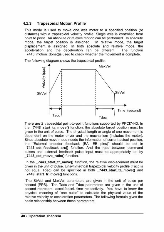
4.1.3 Trapezoidal Motion Profile
This mode is used to move one axis motor to a specified position (ordistance) with a trapezoidal velocity profile. Single axis is controlled frompoint to point. An absolute or relative motion can be performed. In absolutemode, the target position is assigned. In relative mode, the targetdisplacement is assigned. In both absolute and relative mode, theacceleration and the deceleration can be different. The function_7443_motion_done()is used to check whether the movement is complete.
The following diagram shows the trapezoidal profile.
There are 2 trapezoidal point-to-point functions supported by PPCI7443. Inthe _7443_start_ta_move() function, the absolute target position must begiven in the unit of pulse. The physical length or angle of one movement isdependent on the motor driver and the mechanism (includes the motor).Since absolute move mode needs the information of current actual position,the “External encoder feedback (EA, EB pins)” should be set in_7443_set_feedback_src() function. And the ratio between commandpulses and external feedback pulse input must be appropriately set by_7443_set_move_ratio() function.
In the _7443_start_tr_move() function, the relative displacement must begiven in the unit of pulse. Unsymmetrical trapezoidal velocity profile (Tacc isnot equal Tdec) can be specified in both _7443_start_ta_move() and_7443_start_tr_move() functions.
The StrVel and MaxVel parameters are given in the unit of pulse persecond (PPS). The Tacc and Tdec parameters are given in the unit ofsecond represent accel./decel. time respectively. You have to know thephysical meaning of “one pulse” to calculate the physical value of therelative velocity or acceleration parameters. The following formula gives thebasic relationship between these parameters.
Velocity
(pps)
StrVel
Tacc Tdec
MaxVel
StrVel
Time (second)
Operation Theorem • 41
MaxVel = StrVel + accel*Tacc;StrVel = MaxVel + decel *Tdec;
where accel/decel represents the acceleration/deceleration rate in unit ofpps/sec^2. The area inside the trapezoidal profile represents the movingdistance.
The unit of velocity setting is pulses per second (PPS). Usually, the unit ofvelocity in the manual of motor or driver is in rounds per minute (rpm). Asimple conversion is necessary to match between these two units. Here weuse a example to illustrate the conversion.
For example:
A servomotor with a AB phase encoder is used in a X-Y table. Theresolution of encoder is 2000 counts per phase. The maximumrotating speed of motor is designed to be 3600 rpm. What is themaximum pulse command output frequency that you have to set onPPCI7443?
Answer:MaxVel = 3600/60*2000*4
= 48000ppsThe reason why *4 is because there are four states per AB phase (SeeFigures in Section 4.4).
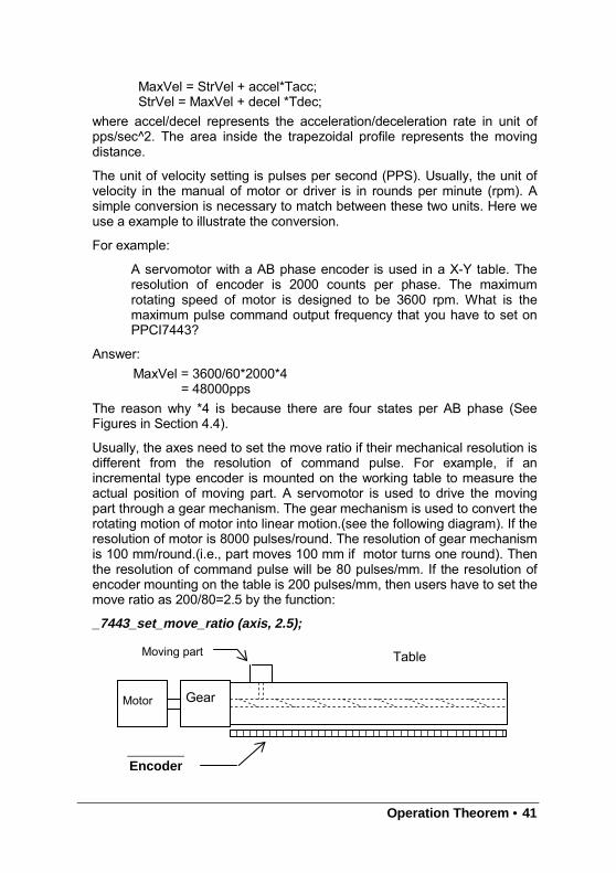
Usually, the axes need to set the move ratio if their mechanical resolution isdifferent from the resolution of command pulse. For example, if anincremental type encoder is mounted on the working table to measure theactual position of moving part. A servomotor is used to drive the movingpart through a gear mechanism. The gear mechanism is used to convert therotating motion of motor into linear motion.(see the following diagram). If theresolution of motor is 8000 pulses/round. The resolution of gear mechanismis 100 mm/round.(i.e., part moves 100 mm if motor turns one round). Thenthe resolution of command pulse will be 80 pulses/mm. If the resolution ofencoder mounting on the table is 200 pulses/mm, then users have to set themove ratio as 200/80=2.5 by the function:
_7443_set_move_ratio (axis, 2.5);
Moving part
Motor Gear
Encoder
Table
42 • Operation Theorem
If this ratio is not set before issuing the start moving command, it will causeproblems when running in “Absolute Mode”. Because the PPCI7443 can’trecognize the actual absolute position during motion.
Relative Functions:_7443_start_ta_move() ,_7443_start_tr_move() : Refer to section 6.6_7443_motion_done(): Refer to section 6.11_7443_set_feedback_src(): Refer to section 6.4_7443_set_move_ratio(): Refer to section 6.6
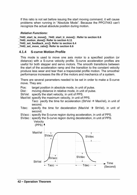
4.1.4 S-curve Motion Profile
This mode is used to move one axis motor to a specified position (ordistance) with a S-curve velocity profile. S-curve acceleration profiles areuseful for both stepper and servo motors. The smooth transitions betweenthe start of the acceleration ramp and the transition to the constant velocityproduce less wear and tear than a trapezoidal profile motion. The smootherperformance increases the life of the motors and mechanics of a system.
There are several parameters needed to be set in order to make a S-curvemove. They are:Pos: target position in absolute mode, in unit of pulse.Dist : moving distance in relative mode, in unit of pulse.StrVel: specify the start velocity, in unit of PPS.MaxVel: specify the maximum velocity, in unit of PPS.
Tacc pecify the time for acceleration (StrVel MaxVel), in unit ofsecond.
Tdec: specify the time for deceleration (MaxVel StrVel), in unit ofsecond.
SVacc : specify the S-curve region during acceleration, in unit of PPS.SVdec : specify the S-curve region during deceleration, in unit of PPS.
Tacc Tdec
SVacc
SVacc SVdec
SVdec
Time(Second)
Velocity(PPS)
StrVel
MaxVel
Operation Theorem • 43
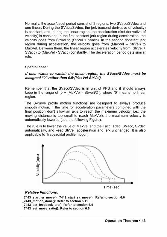
Normally, the accel/decel period consist of 3 regions, two SVacc/SVdec andone linear. During the SVacc/SVdec, the jerk (second derivative of velocity)is constant, and, during the linear region, the acceleration (first derivative ofvelocity) is constant. In the first constant jerk region during acceleration, thevelocity goes from StrVel to (StrVel + Svacc). In the second constant jerkregion during acceleration, the velocity goes from (MaxVel – StrVel) toMaxVel. Between them, the linear region accelerates velocity from (StrVel +SVacc) to (MaxVel - SVacc) constantly. The deceleration period gets similarrule.
Special case:
if user wants to vanish the linear region, the SVacc/SVdec must beassigned “0” rather than 0.5*(MaxVel-StrVel).
Remember that the SVacc/SVdec is in unit of PPS and it should alwayskeep in the range of [0 ~ (MaxVel - Strvel)/2 ], where “0” means no linearregion.
The S-curve profile motion functions are designed to always producesmooth motion. If the time for acceleration parameters combined with thefinal position don’t allow an axis to reach the maximum velocity( i.e.: themoving distance is too small to reach MaxVel), the maximum velocity isautomatically lowered (see the following Figure).
The rule is to lower the value of MaxVel and the Tacc, Tdec, SVacc, SVdecautomatically, and keep StrVel, acceleration and jerk unchanged. It is alsoapplicable to Trapezoidal profile motion.
Relative Functions:_7443_start_sr_move(),_7443_start_sa_move() : Refer to section 6.6_7443_motion_done(): Refer to section 6.11_7443_set_feedback_src(): Refer to section 6.4_7443_set_move_ratio(): Refer to section 6.6
Velocity
(pps)
Time (sec)
44 • Operation Theorem
The Following table shows the difference between all the single axis motionfunctions, including Preset Mode(both trapezoidal and S-curve Motion) andconstant velocity mode .
Velocity ProfileTrapezoidal S-curve Relative Absolute
_7443_tv_move √ N/A ----------- -----------_7443_sv_move N/A √ ----------- -----------
_7443_v_change √ √ ----------- -----------_7443_sd_stop √ √ ----------- -----------_7443_emg_stop() ----------- ------------ ----------- -----------_7443_start_ta_move √ N/A N/A √
_7443_start_tr_move √ N/A √ N/A_7443_start_sr_move N/A √ √ N/A_7443_start_sa_move N/A √ N/A √
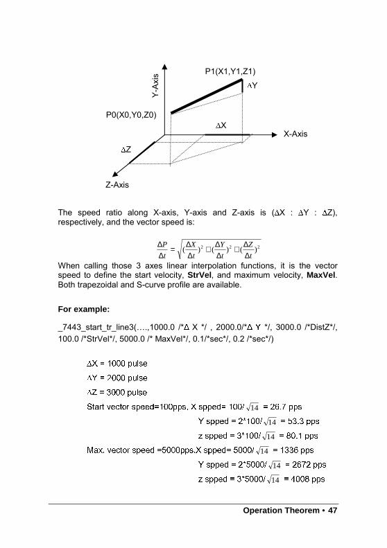
4.1.5 Linear interpolation for 2~4 axes
In this mode, any 2 of the 4, 3 of the 4 or all the 4 axes may be chosen toperform linear interpolation. “Interpolation between multi-axes” means theseaxes “start simultaneously, and reach their ending points at the same time”.Linear means the ratio of speed of every axis is a constant value. Noticethat you can’t use 2 groups of 2 axes linear interpolation in one card at thesame time. But you can use one 2 axes linear and one 2 axes circularinterpolation at the same time. If you want to stop one interpolation group,you can just use _7443_sd_stop() or _7443_emg_stop() with first axis of thegroup as parameter to stop all axes of this interpolation.
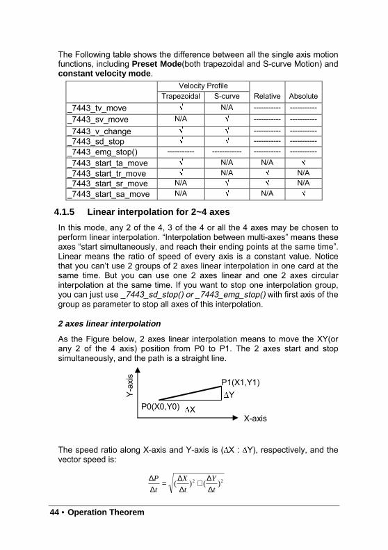
2 axes linear interpolation
As the Figure below, 2 axes linear interpolation means to move the XY(orany 2 of the 4 axis) position from P0 to P1. The 2 axes start and stopsimultaneously, and the path is a straight line.
The speed ratio along X-axis and Y-axis is (∆X : ∆Y), respectively, and thevector speed is:
P0(X0,Y0)
P1(X1,Y1)
X-axis
Y-axis
∆X
∆Y
22 )()(t
Y
t
X
t
P
∆∆+
∆∆=
∆∆
Operation Theorem • 45
When calling the 2 axes linear interpolation functions, it is the vector speedto define the start velocity, StrVel , and maximum velocity, MaxVel , Bothtrapezoidal and S-curve profile are available.
Example:
_7443_start_tr_move_xy(0 , 30000.0 , 40000.0 , 1000.0 , 5000.0 , 0.1,0.2 )
It will cause the X,Y axes (axes 0 & 1) of Card 0 to perform a linearinterpolation movement, in which:
∆
∆
Acceleration time = 0.1 secDeceleration time = 0.2 sec
There are two groups of functions that provide 2 axes linear interpolation.The first group divides the 4 axes into XY (axis 0 & axis 1) and ZU(axis 2 &axis 3). By calling these functions, the target axes are already assigned.
_7443_start_tr_move_xy(), _7443_start_tr_move_zu(),_7443_start_ta_move_xy(), _7443_start_ta_move_zu(),_7443_start_sr_move_xy(), _7443_start_sr_move_zu(),_7443_start_sa_move_xy(), _7443_start_sa_move_zu(),: Refer to section 6.7
The second group allows user to freely assign the 2 target axes._7443_start_tr_line2(), _7443_start_sr_line2(),_7443_start_ta_line2(),_7443_start_sa_line2(),: Refer to section 6.7
The characters “t”, “s”, “r”, “a” after _7443_start means:t – Trapezoidal profiles – S-curve profiler – Relative motiona – Absolute motion
3 axes linear interpolation
Any 3 of the 4 axes of PPCI7443 may perform 3 axes linear interpolation.As the figure below, 3 axes linear interpolation means to move the XYZ (if

46 • Operation Theorem
axes 0, 1, 2 are selected and assigned to be X, Y, Z respectively) positionfrom P0 to P1 and start and stop simultaneously. The path is a straight linein space.
Operation Theorem • 47
The speed ratio along X-axis, Y-axis and Z-axis is (∆X : ∆Y : ∆Z),respectively, and the vector speed is:
When calling those 3 axes linear interpolation functions, it is the vectorspeed to define the start velocity, StrVel , and maximum velocity, MaxVel .Both trapezoidal and S-curve profile are available.
For example:
_7443_start_tr_line3(….,1000.0 /* X */ , 2000.0/* */, 3000.0 /*DistZ*/,100.0 /*StrVel*/, 5000.0 /* MaxVel*/, 0.1/*sec*/, 0.2 /*sec*/)
∆
∆
∆
14 !
" 14
#" 14
14
" 14 !
#" 14
222 )()()(t
Z
t
Y
t
X
t
P
∆∆+
∆∆+
∆∆=
∆∆
P0(X0,Y0,Z0)
P1(X1,Y1,Z1)
X-Axis
Y-Axis
∆X
∆Y
Z-Axis
∆Z
48 • Operation Theorem
These functions related to 3 axes linear interpolation are listed below:_7443_start_tr_line3(), _7443_start_sr_line3()_7443_start_ta_line3() , _7443_start_sa_line3(): Refer to section 6.7
The characters “t”, “s”, “r”, “a” after _7443_start means:t – Trapezoidal profiles – S-curve profiler – Relative motiona – Absolute motion
4 axes linear interpolation
In 4 axes linear interpolation, the speed ratio along X-axis, Y-axis, Z-axisand U-axis Is (∆X: ∆Y: ∆Z: ∆U), respectively, and the vector speed is:
The functions related to 4 axes linear interpolation are listed below:_7443_start_tr_line4(), _7443_start_sr_line4()_7443_start_ta_line4(),_7443_start_sa_line4(): Refer to section 6.7
The characters “t”, “s”, “r”, “a” after _7443_start means:t – Trapezoidal profiles – S-curve profiler – Relative motiona – Absolute motion
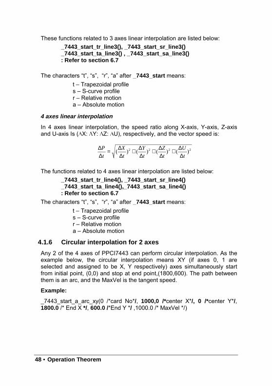
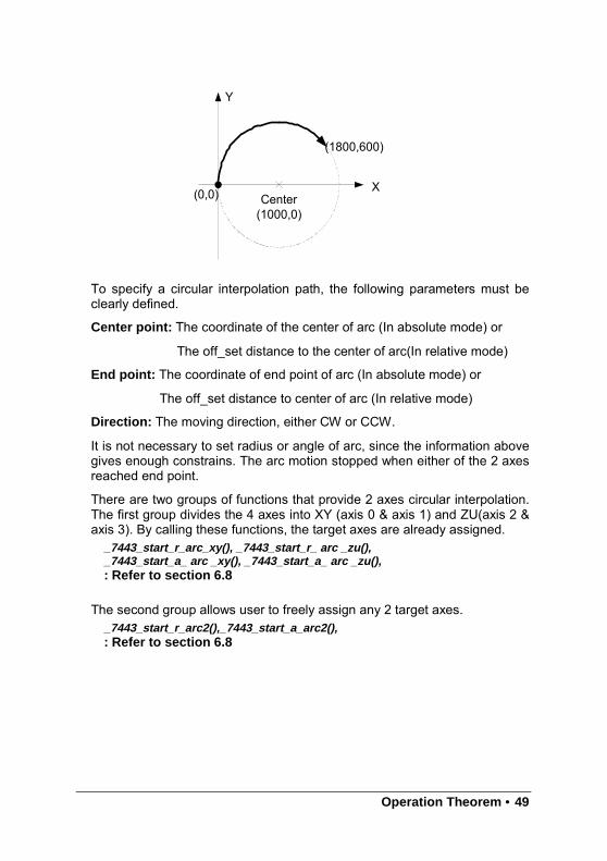
4.1.6 Circular interpolation for 2 axes
Any 2 of the 4 axes of PPCI7443 can perform circular interpolation. As theexample below, the circular interpolation means XY (if axes 0, 1 areselected and assigned to be X, Y respectively) axes simultaneously startfrom initial point, (0,0) and stop at end point,(1800,600). The path betweenthem is an arc, and the MaxVel is the tangent speed.
Example:
_7443_start_a_arc_xy(0 /*card No*/, 1000,0 /*center X*/, 0 /*center Y*/,1800.0 /* End X */, 600.0 /*End Y */ ,1000.0 /* MaxVel */)
2222 )()()()(t
U
t
Z
t
Y
t
X
t
P
∆∆+
∆∆+
∆∆+
∆∆=
∆∆
Operation Theorem • 49
To specify a circular interpolation path, the following parameters must beclearly defined.
Center point: The coordinate of the center of arc (In absolute mode) or
The off_set distance to the center of arc(In relative mode)
End point: The coordinate of end point of arc (In absolute mode) or
The off_set distance to center of arc (In relative mode)
Direction: The moving direction, either CW or CCW.
It is not necessary to set radius or angle of arc, since the information abovegives enough constrains. The arc motion stopped when either of the 2 axesreached end point.
There are two groups of functions that provide 2 axes circular interpolation.The first group divides the 4 axes into XY (axis 0 & axis 1) and ZU(axis 2 &axis 3). By calling these functions, the target axes are already assigned.
_7443_start_r_arc_xy(), _7443_start_r_ arc _zu(),_7443_start_a_ arc _xy(), _7443_start_a_ arc _zu(),: Refer to section 6.8
The second group allows user to freely assign any 2 target axes._7443_start_r_arc2(),_7443_start_a_arc2(),: Refer to section 6.8
X
Y
(0,0) Center(1000,0)
(1800,600)
50 • Operation Theorem
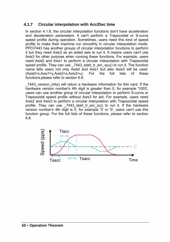
4.1.7 Circular interpolation with Acc/Dec time
In section 4.1.6, the circular interpolation functions don't have accelerationand deceleration parameters. It can't perform a Trapezoidal or S-curvespeed profile during operation. Sometimes, users need this kind of speedprofile to make their machine run smoothly in circular interpolation mode.PPCI7443 has another groups of circular interpolation functions to performit but they need Axis3 as an aided axis to run it. It means users can't useAxis3 for other purpose when running these functions. For example, usersneed Axis0 and Axis1 to perform a circular interpolation with Trapezoidalspeed profile. They can use _7443_start_tr_arc_xyu() to run it. The functionname tells users not only Axis0 and Axis1 but also Axis3 will be used.(Axis0=x,Axis1=y,Axis2=z,Axis3=u). For the full lists of thesefunctions,please refer to section 6.8.
_7443_version_info() will return a hardware information for this card. If thehardware version number's 4th digit is greater than 0, for example '1003',users can use another group of circular interpolation to perform S-curve orTrapezoidal speed profile without Axis3 for aid. For example, users needAxis2 and Axis3 to perform a circular interpolation with Trapezoidal speedprofile. They can use _7443_start_tr_arc_zu() to run it. If the hardwareversion number's 4th digit is 0, for example '3' or '0', users can't use thisfunction group. For the full lists of these functions, please refer to section6.8.
Time
Speed
(pps)
Tsacc
Tlacc
Tsacc
Operation Theorem • 51
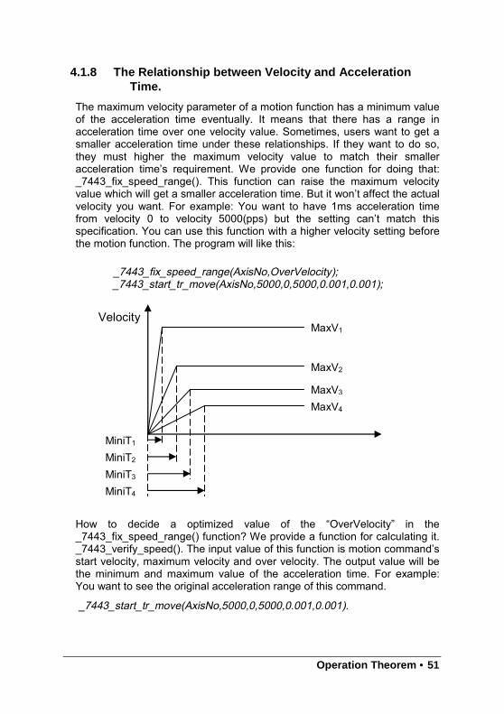
4.1.8 The Relationship between Velocity and AccelerationTime.
The maximum velocity parameter of a motion function has a minimum valueof the acceleration time eventually. It means that there has a range inacceleration time over one velocity value. Sometimes, users want to get asmaller acceleration time under these relationships. If they want to do so,they must higher the maximum velocity value to match their smalleracceleration time’s requirement. We provide one function for doing that:_7443_fix_speed_range(). This function can raise the maximum velocityvalue which will get a smaller acceleration time. But it won’t affect the actualvelocity you want. For example: You want to have 1ms acceleration timefrom velocity 0 to velocity 5000(pps) but the setting can’t match thisspecification. You can use this function with a higher velocity setting beforethe motion function. The program will like this:
_7443_fix_speed_range(AxisNo,OverVelocity);_7443_start_tr_move(AxisNo,5000,0,5000,0.001,0.001);
How to decide a optimized value of the “OverVelocity” in the_7443_fix_speed_range() function? We provide a function for calculating it._7443_verify_speed(). The input value of this function is motion command’sstart velocity, maximum velocity and over velocity. The output value will bethe minimum and maximum value of the acceleration time. For example:You want to see the original acceleration range of this command.
_7443_start_tr_move(AxisNo,5000,0,5000,0.001,0.001).
MiniT1MiniT2MiniT3MiniT4
MaxV1
MaxV2
MaxV3
MaxV4
Velocity
52 • Operation Theorem
You can try this function:
_7443_verify_speed(0,5000,&minAccT, &maxAccT,5000);
The value of minAccT will be 0.0267sec and maxAccT will be 873.587sec.This minimum acceleration time can’t match our requirements, so we mustuse over speed value to do that.
If we use over speed as 20000,
_7443_verify_speed(0,5000,&minAccT, &maxAccT,20000);
The value of miniAccT will be 0.00666sec and maxAccT will be 218.387sec.This minimum acceleration time still can’t match our requirements. If we useover speed as 140000,
_7443_verify_speed(0,5000,&minAccT, &maxAccT,140000);
The value of miniAccT will be 0.000948sec and maxAccT will be 31.08sec.This minimum acceleration time can match our requirements. So, themotion command will be like this.
_7443_fix_speed_range(AxisNo,140000);
_7443_start_tr_move(AxisNo,5000,0,5000,0.001,0.001);
[Note1] The return value of _7443_verify_speed() is a minimum velocity ofyour motion command, it will not always equal to your start velocity setting.In the above example, it will be 3pps more than your 0pps setting.
[Note2] Once you don’t need a fixed over speed setting, you can use_7443_unfix_speed_range() to disable it.
[Note3] Don’t try to use the over speed all the time, you must know whenyou need it. Remember that more over speed setting will results in coarserspeed interval.
Operation Theorem • 53
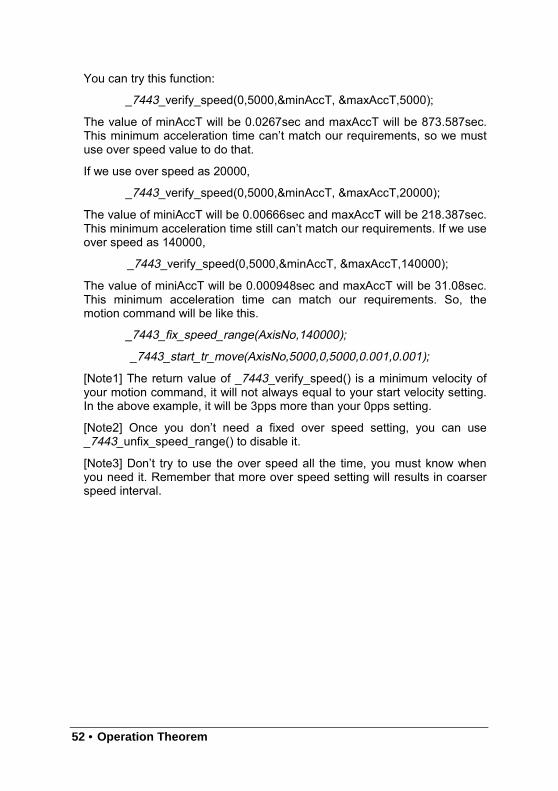
Example:
User’s Desired Profile : ( MaxV2 , Target T ) But this is not possible underthis MaxV2 according to (MaxV, MiniT) relationship. So we must change the(MaxV, MiniT) relationship to a higher one, (MaxV1 , MiniT1 ). Finally, thecommand would be
_7443_fix_speed_range(AxisNo, MaxV1);
_7443_start_tr_move(AxisNo,Distance, 0 , MaxV2 , Target T, Target T);
Relative Functions:_7443_fix_speed_range(), _7443_unfix_speed_range(),_7443_verify_speed(): Refer to section 6.5
Target T
MiniT2
MaxV1
MaxV2
Velocity
MiniT1
54 • Operation Theorem
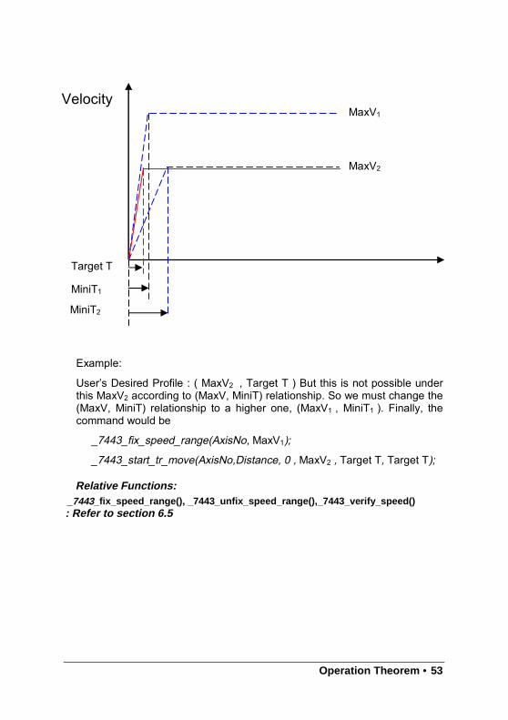
4.1.9 Continuous motion
The PPCI7443 allow user to perform continuous motion. Both single axismovement (section 4.1.3: Trapezoidal, section 4.1.4: S-curve) and multi-axis interpolation (4.1.5: linear interpolation, 4.1.6: circular interpolation) canbe extended to be continuous motion.
For example, if user calls the follow function to perform a single axis presetmotion:
_7443_start_ta_move(0,50000.0,100.0,30000.0,0.1,0.0)
It will cause the axis “0” to move to position “50000.0”, before the axisarrives, user can call a second pressed motion:
_7443_start_tr_move(0,20000.0,100.0,30000.0,0.0,0.2)
The second function call won’t affect the first one, actually it will beexecuted and write into the pre-register in PPCI7443. After the first move isfinished, PPCI7443 will continue the second move according to the pre-register value. So, no time interval exists between these two moves. Andpulses will be continuously generated at the instant of position “50000.0”
The working theory of continuous motion is described below:
working theory of continuous motion
The following diagram shows the register data flow of PPCI7443.
RunningRegister
Pre-reg1
Pre-reg2
Pre-register emptyinterrupt
HostProgram
Next Commandloading
Operation Theorem • 55
Step 0: All Register and Pre-Register is empty.
Step 1: The first motion is executed and CPU writes corresponding valuesinto pre-register 2.
_7443_start_ta_move(0,50000.0,100.0,30000.0,0.1,0.0)
Step 2: Since Pre-register1 & Register is empty, the data in pre-register 2 ismoved to Register automatically and executed instantly by ASIC.
Step 3: Then second function is called. CPU writes the correspondingvalues into pre-register2.
_7443_start_tr_move(0,20000.0,100.0,30000.0,0.0,0.2)
Step 4: Since Pre-register1 is empty; the data in pre-register 2 is moved toPre-register1 automatically and wait to be executed.
Step 5: Now user can execute 3rd function, and it will be stored in Pre-register2
Step 6: When the first function finished, the Register becomes empty, anddata in pre-register1 is allowed to move to register then executed instantlyby ASIC, and, data in pre-register2 is moved to pre-register1.
Step 7: The ASIC will inform CPU by interrupt that motion is completed. Anduser can write 4th motion into Pre-Register 2.
Procedures to perform continuous motion
The following procedures are to help user making continuous motion.
Step 1:
(if Under Dos)
Enable the interrupt service by _7443_int_contol()
(if Under Windows)
Enable the interrupt service by _7443_int_contol() and_7443_int_enable() .
Step 2: Set bit “2” of INT factor to be “True” by _7443_set_int_factor()
Step 3: Set the “conti_logic” to be “1” by: _7443_set_continuous_move()(note: if all motions are of relative mode, this function could beignored. )
Step 4: Call the first three motion functions.
Step 5: Wait for INT(under DOS) or EVENT(under Windows) of pre-registerempty.
56 • Operation Theorem
Step 6: call the 4th motion function.
Step 7: Wait for INT(if under DOS) / EVENT(if under Windows) of pre-register empty.
Step 8: call the 5th motion function.
(Repeat 7 , 8 ……continue…..)
Step n: Call the last motion function and wait for all moves completion.
(note: Another way to detect completion of motion is by poling. User mayconstantly check the buffer status by _7443_check_continuous_buffer() .)
Restrictions of continuous motion
The statements below are restrictions and suggestions for continuousmotion:
1. While Pre-register is not empty, user may not execute any more motion.Otherwise, the new one will overwrite the previous in pre-register2.
2. To get a continuity of velocity between 2 motions, the end velocity ofprevious and starting velocity of next must be the same. There areseveral methods to achieve this. The easiest way is to set thedeceleration/acceleration time to be ‘0’.
For example :
1st motion: _7443_start_tr_move_XY(0,1000,0,0,5000,0.2, 0.0)
(Start a relative 2-axis linear interpolation, x distance=1000, ydistance= 0 , start vel = 0, max vel = 5000, Tacc = 0.2, Tdec = 0)
2nd motion: _7443_start_r_arc_xy(0,0,500,500,500,1,5000);
(Start a relative 2-axis circular interpolation, center x distance=0,center y distance= 500 , End x distance = 500, end y distance =500. max vel = 5000. It is a quarter ccw circle, with velocity = 5000 )
3rd motion: _7443_start_tr_move_XY(0,0,1000,0,5000,0.0, 0.2)
(Start a relative 2-axis linear interpolation, x distance=0, ydistance= 1000 , start vel = 0, max vel = 5000, Tacc = 0.0,Tdec = 0)
Operation Theorem • 57
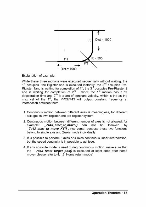
Explanation of example:
While these three motions were executed sequentially without waiting, the1st occupies the Rigister and is executed instantly; the 2nd occupies Pre-Rigister 1and is waiting for completion of 1st; the 3rd occupies Pre-Rigister 2and is waiting for completion of 2nd . Since the 1st motion has a ‘0’deceleration time and 2nd is a arc of constant velocity, which is the as themax vel of the 1st, the PPCI7443 will output constant frequency atintersection between them.
1. Continuous motion between different axes is meaningless, for differentaxis get its own register and pre-register system.
2. Continuous motion between different number of axes is not allowed, forexample: _7443_start_tr_move() can not be followed by_7443_start_ta_move_XY() , vice versa, because these two functionsbelong to single axis and 2-axis mode individually.
3. It is possible to perform 3 axes or 4 axes continuous linear interpolation,but the speed continuity is impossible to achieve.
4. If any absolute mode is used during continuous motion, make sure thatthe _7443_reset_target_pos() is executed at least once after homemove.(please refer to 4.1.8: Home return mode)
Dist = 1000
Dist = 1000
R = 500(1)(2)
(3)
58 • Operation Theorem
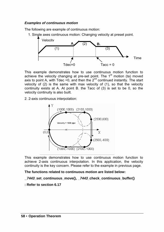
Examples of continuous motion
The following are example of continuous motion:1. Single axes continuous motion: Changing velocity at preset point.
This example demonstrates how to use continuous motion function toachieve the velocity changing at pre-set point. The 1st motion (ta) movedaxis to point A, with Tdec =0, and then the 2nd continued instantly. The startvelocity of (2) is the same with max velocity of (1), so that the velocitycontinuity exists at A. At point B. the Tacc of (3) is set to be 0, so thevelocity continuity is also built.
2. 2-axis continuous interpolation:
This example demonstrates how to use continuous motion function toachieve 2-axis continuous interpolation. In this application, the velocitycontinuity is the key concern. Please refer to the example in previous page.
The functions related to continuous motion are listed below:
_7443_set_continuous_move(), _ 7443_check_continuous_buffer()
: Refer to section 6.17
Time
Velocity
Tdec=0 Tacc = 0
(1)(2)
(3)A. B.
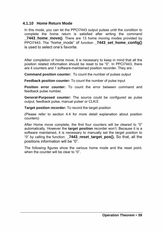
Operation Theorem • 59
4.1.10 Home Return Mode
In this mode, you can let the PPCI7443 output pulses until the condition tocomplete the home return is satisfied after writing the command_7443_home_move (). There are 13 home moving modes provided byPPCI7443. The “home_mode” of function _7443_set_home_config()is used to select one’s favorite.
After completion of home move, it is necessary to keep in mind that all theposition related information should be reset to be “0”. In PPCI7443, thereare 4 counters and 1 software-maintained position recorder. They are :
Command position counter: To count the number of pulses output
Feedback position counter: To count the number of pulse input
Position error counter: To count the error between command andfeedback pulse number.
General-Purposed counter: The source could be configured as pulseoutput, feedback pulse, manual pulser or CLK/2.
Target position recorder: To record the target position
(Please refer to section 4.4 for more detail explanation about positioncounters)
After Home move complete, the first four counters will be cleared to “0”automatically. However the target position recorder won’t. Because it is asoftware maintained, it is necessary to manually set the target position to“0” by calling the function: _7443_reset_target_pos(). So that, all thepositions information will be “0”.The following figures show the various home mode and the reset point,when the counter will be clear to “0”.
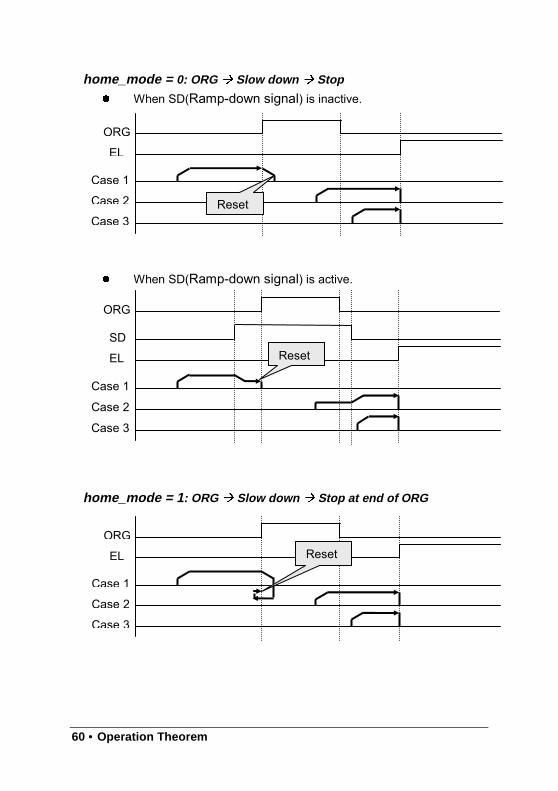
60 • Operation Theorem
home_mode = 0: ORG Slow down Stop
When SD(Ramp-down signal) is inactive.
When SD(Ramp-down signal) is active.
home_mode = 1 : ORG Slow down Stop at end of ORG
ORG
EL
Case 1
Case 2
Case 3Reset
ORG
EL
Case 1
Case 2
Case 3
SDReset
ORG
EL
Case 1
Case 2
Case 3
Reset
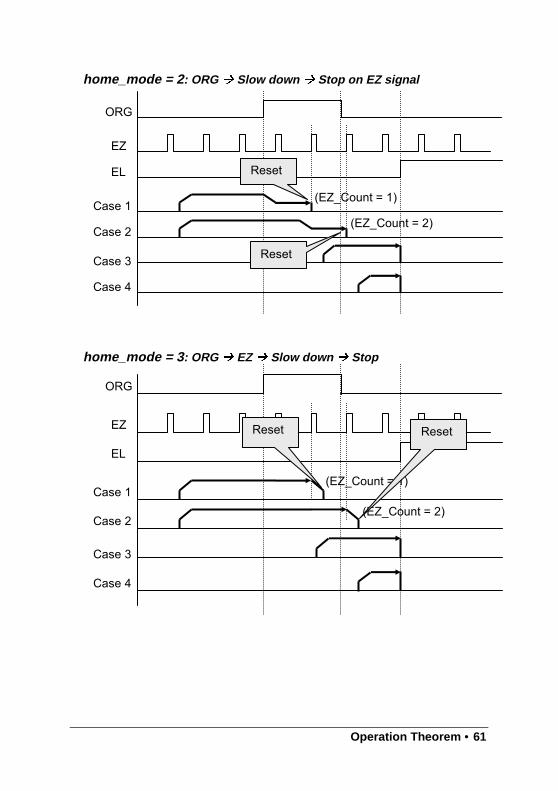
Operation Theorem • 61
home_mode = 2 : ORG Slow down Stop on EZ signal
home_mode = 3 : ORG EZ Slow down Stop
ORG
EL
Case 1
Case 3
Case 4
EZ
Case 2
(EZ_Count = 1)
(EZ_Count = 2)
Reset
Reset
ORG
EL
Case 1
Case 3
Case 4
EZ
Case 2
(EZ_Count = 1)
(EZ_Count = 2)
Reset Reset
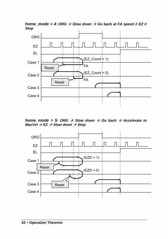
62 • Operation Theorem
home_mode = 4 : ORG Slow down Go back at FA speed EZStop
home_mode = 5 : ORG Slow down Go back Accelerate toMaxVel EZ Slow down Stop
ORG
EL
Case 1
Case 3
Case 4
EZ
Case 2
(EZ_Count = 1)
(EZ_Count = 0)
FA
FA
Reset
Reset
ORG
EL
Case 1
Case 3
Case 4
EZ
Case 2
(EZD = 1)
(EZD = 0)Reset
Reset
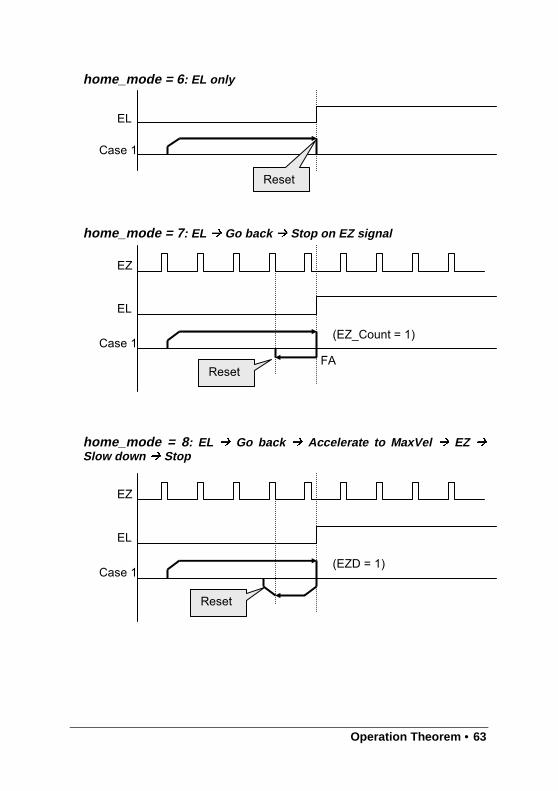
Operation Theorem • 63
home_mode = 6 : EL only
home_mode = 7 : EL Go back Stop on EZ signal
home_mode = 8 : EL Go back Accelerate to MaxVel EZ Slow down Stop
EL
Case 1
Reset
EL
Case 1
EZ
FA
(EZ_Count = 1)
Reset
EL
Case 1
EZ
(EZD = 1)
Reset
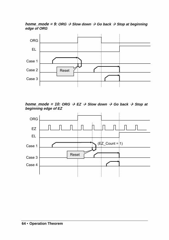
64 • Operation Theorem
home_mode = 9 : ORG Slow down Go back Stop at beginningedge of ORG
home_mode = 10 : ORG EZ Slow down Go back Stop atbeginning edge of EZ
ORG
EL
Case 1
Case 2
Case 3
Reset
ORG
EL
Case 1
Case 3
Case 4
EZ
(EZ_Count = 1)
Reset
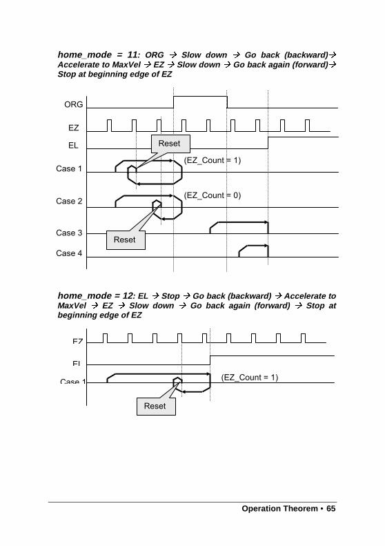
Operation Theorem • 65
home_mode = 11 : ORG Slow down Go back (backward) Accelerate to MaxVel EZ Slow down Go back again (forward) Stop at beginning edge of EZ
home_mode = 12 : EL Stop Go back (backward) Accelerate toMaxVel EZ Slow down Go back again (forward) Stop atbeginning edge of EZ
ORG
EL
Case 1
Case 3
Case 4
EZ
Case 2
(EZ_Count = 1)
(EZ_Count = 0)
Reset
Reset
EL
Case 1
EZ
(EZ_Count = 1)
Reset
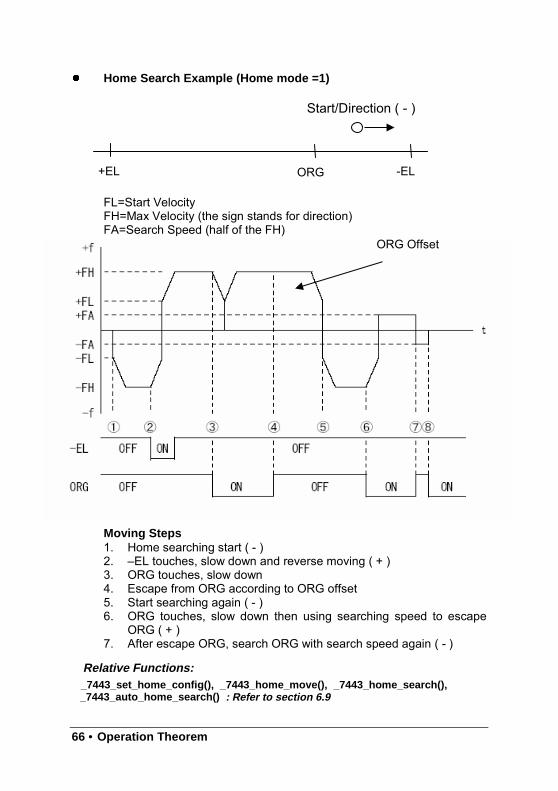
66 • Operation Theorem
Home Search Example (Home mode =1)
FL=Start VelocityFH=Max Velocity (the sign stands for direction)FA=Search Speed (half of the FH)
Relative Functions:Moving Steps1. Home searching start ( - )2. –EL touches, slow down and reverse moving ( + )3. ORG touches, slow down4. Escape from ORG according to ORG offset5. Start searching again ( - )6. ORG touches, slow down then using searching speed to escape
ORG ( + )7. After escape ORG, search ORG with search speed again ( - )
Relative Functions:_7443_set_home_config(), _7443_home_move(), _7443_home_search(),_7443_auto_home_search() : Refer to section 6.9
ORG+EL -EL
Start/Direction ( - )
ORG Offset
Operation Theorem • 67
4.1.11 Manual Pulser Mode
For manual operation of a device, you may use a manual pulser such as arotary encoder. The PPCI7443 can input signals from the pulser and outputcorresponding pulses from the OUT and DIR pins, thereby allowing you tosimplify the external circuit and control the present position of axis. Thismode is effective when a _7443_pulser_vmove(), _7443_pulser_pmove()or _7443_pulser_home_move() command has been called. To stop, by a_7443_sd_stop() or_7443_emg_stop() command or till satisfaction ofmovement.
The PPCI7443 receives plus and minus pulses (CW/CCW) or 90 degreesphase difference signals(AB phase) from the pulser at PA and PB pins. Toset the input signal modes of pulser, use _7443_set_pulser_iptmode()function. The 90° phase difference signals can be input throughmultiplication by 1, 2 or 4. If the AB phase input mode is selected, the PAand PB signals should be with 90° phase shifted, and the position countingis increasing when the PA signal is leading the PB signal by 90° phase.
Relative Functions:
_7443_pulser_vmove(), _7443_pulser_pmove(), _7443_pulser_home_move(),
_7443_set_pulser_iptmode(): Refer to section 6.10
4.1.12 Timer Mode
In this mode, user can delay the execution of program by a specified delaytime (msec).
For example._7443_delay_time (0, 100); after executing this command,there will be 100 msec delay before executing next command.It is the
Relative Functions:
_7443_delay_time(): Refer to Section 6.1
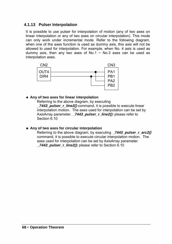
68 • Operation Theorem
4.1.13 Pulser Interpolation
It is possible to use pulser for interpolation of motion (any of two axes onlinear interpolation or any of two axes on circular interpolation). This modecan only work under incremental mode. Refer to the following diagram,when one of the axes function is used as dummy axis, this axis will not beallowed to used for interpolation. For example, when No. 4 axis is used asdummy axis, then any two axes of No.1 ~ No.3 axes can be used asinterpolation axes.
Any of two axes for linear interpolationReferring to the above diagram, by executing_7443_pulser_r_line2() command, it is possible to execute linearinterpolation motion. The axes used for interpolation can be set byAxisArray parameter. _7443_pulser_r_line2(): please refer toSection 6.10
Any of two axes for circular interpolationReferring to the above diagram, by executing _7443_pulser_r_arc2()command, it is possible to execute circular interpolation motion. Theaxes used for interpolation can be set by AxisArray parameter._7443_pulser_r_line2(): please refer to Section 6.10
PB1PA1
CN3
PB2PA2
DIR4OUT4
CN2
Operation Theorem • 69
4.2 The motor driver interface
The PPCI7443 provides the INP, ALM, ERC, SVON, RDY signals forservomotor driver’s control interface. The INP and ALM are used forfeedback the servo driver’s status. The ERC is used to reset the servodriver’s deviation counter under special conditions. The SVON is general-purposed output signal, and RDY is general-purposed input signal. Themeaning of “general-purposed” is that the processing of signal is not abuild-in procedure of hardware. The hardware processes INP, ALM andERC signals according to pre-defined rule. For example, when receivingALM signal, the PPCI7443 stop or decelerate to stop output pulsesautomatically. However, SVON and RDY are not that case, they actually actlike common I/O.
4.2.1 INP
The processing of INP signal is a hardware build-in procedure, and it isdesigned to cooperate with the in-position signal of servomotor driver.
Usually, servomotor driver with pulse train input has a deviation (positionerror) counter to detect the deviation between the input pulse command andfeedback counter. The driver controls the motion of servomotor to minimizethe deviation until it becomes 0. Theoretically, the servomotor operateswith some time delay from command pulses. Accordingly, when the pulsegenerator stops outputting pulses, the servomotor does not stop but keeprunning until the deviation counter become zero. Then, the servo driversends out the in-position signal (INP) to the pulse generator to indicate themotor stops running.
Usually, the PPCI7443 stops outputting pulses upon completion ofoutputting designated pulses. But by setting parameter inp_enable in_7443_set_inp() function, you can delay the completion of motion to thetime when the INP signal is turned on, ie, the motor arrives the targetposition. Status of _7443_motion_done() and INT signal are also delayed.That is, when performing under position control mode, the completion of_7443_start_ta_move() , _7443_start_sr_move() ,…etc, is delayed untilINP signal is turned ON.
The in-position function can be enable or disable, and the input logicpolarity is also programmable by parameter “inp_logic” of _7443_set_inp() .The INP signal status can be monitored by software function:_7443_get_io_status() .
Relative Functions:_7443_set_inp() : Refer to section 6.12_7443_get_io_status() : Refer to section 6.13_7443_motion_done() : Refer to section 6.11
70 • Operation Theorem
4.2.2 ALM
The processing of ALM signal is a hardware build-in procedure, and it isdesigned to cooperate with the alarm signal of servomotor driver.
The ALM signal is an output from servomotor driver. Usually, It is designedto inform that something wrong with the driver or motor.
The ALM pin receives the alarm signal output from the servo driver. Thesignal immediately stops the PPCI7443 from generating pulses or stops itafter deceleration. If the ALM signal is in the ON status at the start, thePPCI7443 outputs the INT signal without generating any command pulse.The ALM signal may be a pulse signal, of which the shortest width is a timelength of 5 microseconds.
You can change the input logic of ALM by set the parameter “alm_logic ” of_7443_set_alm function and the stop mode by “alm_mode”. Whether ornot the PPCI7443 is generating pulses, the ALM signal lets it output the INTsignal.. The ALM status can be monitored by software function:_7443_get_io_status() . The ALM signal can generate IRQ if the interruptservice is enabled, please refer to section 4.7.
Relative Functions:_7443_set_alm() : Refer to section 6.12_7443_get_io_status() : Refer to section 6.13
Operation Theorem • 71
4.2.3 ERC
The ERC signal is an output from PPCI7443. The processing of ERC signalis a hardware build-in procedure, and it is designed to cooperate with thedeviation counter clear signal of servomotor driver.
The deviation counter clear signal is inserted in the following 4 situations:
1home return is complete;2 the end-limit switch is active;3an alarm signal stops OUT and DIR signals;4an emergency stop command is issued by software operator.
Since the servomotor operates with some delay from pulse generated fromthe PPCI7443, it keeps moving till the deviation counter of the driver downto zero even if the PPCI7443 stop outputting pulses because of the ±ELsignal or the completion of home return. The ERC signal allows you toimmediately stop the servomotor by resetting the deviation counter to zero.The ERC signal is output as an one-shot signal. The pulse width is a timelength defined by function call _7443_set_erc() . The ERC signal willautomatically output when ±EL signals, ALM signal is turned on toimmediately stop the servomotor.
Relative Functions:_7443_set_erc() : Refer to section 6.12
4.2.4 SVON and RDY
In PPCI7443, every axis is equipped with SVON and RDY, which aregeneral-purposed output and input channels, respectively. Usually, theSVON is useful to cooperate with servomotor drivers as Servo ONcommand, and RDY to receive the Servo Ready signal from servomotordrivers. That is the reason why they are named as SVON and RDY. Thereis no build-in procedure for SVON and RDY.
The SVON signals are controlled by software function: _7443_Set_Servo() .
RDY pins are dedicated for digital input use. The status of this signal can bemonitored by software function _7443_get_io_status() .
Relative Functions:
_7443_Set_Servo(): Refer to section 6.12_7443_get_io_status(): Refer to section 6.13
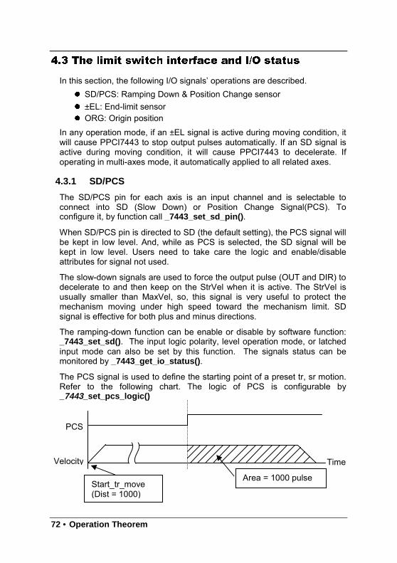
72 • Operation Theorem
4.3 The limit switch interface and I/O status
In this section, the following I/O signals’ operations are described. SD/PCS: Ramping Down & Position Change sensor ±EL: End-limit sensor ORG: Origin position
In any operation mode, if an ±EL signal is active during moving condition, itwill cause PPCI7443 to stop output pulses automatically. If an SD signal isactive during moving condition, it will cause PPCI7443 to decelerate. Ifoperating in multi-axes mode, it automatically applied to all related axes.
4.3.1 SD/PCS
The SD/PCS pin for each axis is an input channel and is selectable toconnect into SD (Slow Down) or Position Change Signal(PCS). Toconfigure it, by function call _7443_set_sd_pin() .
When SD/PCS pin is directed to SD (the default setting), the PCS signal willbe kept in low level. And, while as PCS is selected, the SD signal will bekept in low level. Users need to take care the logic and enable/disableattributes for signal not used.
The slow-down signals are used to force the output pulse (OUT and DIR) todecelerate to and then keep on the StrVel when it is active. The StrVel isusually smaller than MaxVel, so, this signal is very useful to protect themechanism moving under high speed toward the mechanism limit. SDsignal is effective for both plus and minus directions.
The ramping-down function can be enable or disable by software function:_7443_set_sd() . The input logic polarity, level operation mode, or latchedinput mode can also be set by this function. The signals status can bemonitored by _7443_get_io_status() .
The PCS signal is used to define the starting point of a preset tr, sr motion.Refer to the following chart. The logic of PCS is configurable by_7443_set_pcs_logic()
Start_tr_move(Dist = 1000)
Area = 1000 pulse
PCS
Velocity Time
Operation Theorem • 73
Relative Functions:
_7443_set_sd_pin(),_ 7443_set_pcs_logic(): Refer to section 6.5_7443_set_sd(): Refer to section 6.12_7443_get_io_status(): Refer to section 6.13
4.3.2 EL
The end-limit signals are used to stop the control output signals (OUT andDIR) when the end-limit is active. There are two possible stop modes, oneis “stop immediately”, and, the other is “decelerate to StrVel then stop”. Toselect the mode: _7443_set_el().
PEL signal indicates end-limit in positive (plus) direction. MEL signalindicates end-limit in negative (minus) direction. When the output pulsesignals (OUT and DIR) are toward positive direction, the pulse train will beimmediately stopped when the PEL signal is inserted, while the MEL signalis meaningless in this case, and vise versa. When the PEL is inserted, onlythe negative (minus) direction output pulse can be generated for moving themotor to negative (minus) direction.
The EL signal can generate IRQ if the interrupt service is enabled, pleaserefer to section 4.7.
You can use either ‘a’ contact switch or ‘b’ contact switch by setting the dipswitch S1. The PPCI7443 is delivered from the factory with all bits of S1set to ON.
The signal status can be monitored by software function:_7443_get_io_status().
Relative Functions:
_7443_set_el(): Refer to section 6.12_7443_get_io_status(): Refer to section 6.13
4.3.3 ORG
The ORG signal is used, when the motion controller is operated at thehome return mode. There are 13 home return modes (please refer tosection 4.1.8), you can select one of them by setting “home_mode”argument in software function: _7443_set_home_config() . The logicpolarity of the ORG signal, level input or latched input mode are selectableby this software function.
After setting the configuration of home return mode by_7443_set_home_config() , a _7443_home_move() command canperform the home return function.
Relative Functions:

74 • Operation Theorem
_7443_set_home_config(),_7443_home_move(): Refer to section 6.9
Operation Theorem • 75
4.4 The Counters
The PPCI7443 provides 4 counters for every axis, and, they are introducedin this section:
Command position counter: To count the number of pulses output
Feedback position counter: To count the number of pulse input
Position error counter: To count the error between command andfeedback pulse number.
General-Purposed counter: The source could be configured as pulseoutput, feedback pulse, manual pulser or CLK/2.
Also, the target position recorder , a software-maintained position recorder,is discussed.
4.4.1 Command position counter
The command position counter is a 28-bits binary up/down counter, and itsinput source is the output pulse from PPCI7443, thus, it provide as exactinformation of current command position. Note: the command position isdifferent from target position. The command position increases ordecreases as pulse output, while the target position changes only when anew motion command was executed. The target position is recorded bysoftware, and need manually resetting after home move completed.
The command position counter will be clear to “0” automatically after homemove completed. Besides, the function call, _7443_set_command() , canbe executed in any time to set an new command position value. To readcurrent command position: _7443_get_command().
Relative Functions:_7443_set_command(),_7443_get_command(): Refer to section 6.15
4.4.2 Feedback position counter
The PPCI7443 has a 28-bits binary up/down counter for managing thepresent position feedback for each axis. The counter counts signals inputfrom EA and EB pins.
It can accept 2 kinds of pulse input: (1). plus and minus pulsesinput(CW/CCW mode); (2). 90 phase difference signals(AB phase mode).
90 phase difference signals may be selected to be multiplied by a factor of
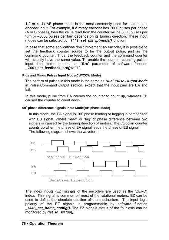
76 • Operation Theorem
1,2 or 4. 4x AB phase mode is the most commonly used for incrementalencoder input. For example, if a rotary encoder has 2000 pulses per phase(A or B phase), then the value read from the counter will be 8000 pulses perturn or –8000 pulses per turn depends on its turning direction. These inputmodes can be selected by _7443_set_pls_iptmode() function.
In case that some applications don’t implement an encoder, it is possible toset the feedback counter source to be the output pulse, just as thecommand counter. Thus, the feedback counter and the command counterwill actually have the same value. To enable the counters counting pulsesinput from pulse output, set “Src ” parameter of software function_7443_set_feedback_src () to “1”.
Plus and Minus Pulses Input Mode(CW/CCW Mode)
The pattern of pulses in this mode is the same as Dual Pulse Output Modein Pulse Command Output section, expect that the input pins are EA andEB.
In this mode, pulse from EA causes the counter to count up, whereas EBcaused the counter to count down.
90 phase difference signals Input Mode(AB phase Mode)
In this mode, the EA signal is 90 phase leading or lagging in comparisonwith EB signal. Where “lead” or “lag’ of phase difference between twosignals is caused by the turning direction of motors. The up/down countercounts up when the phase of EA signal leads the phase of EB signal.The following diagram shows the waveform.
The index inputs (EZ) signals of the encoders are used as the “ZERO”index. This signal is common on most of the rotational motors. EZ can beused to define the absolute position of the mechanism. The input logicpolarity of the EZ signals is programmable by software function_7443_set_home_config(). The EZ signals status of the four axis can bemonitored by get_io_status() .
EA
EB
Negative Direction
EA
EB
Positive Direction
Operation Theorem • 77
The feedback position counter will be clear to “0” automatically after homemove completed. Besides, the function call, _7443_set_position() , can beexecuted in any time to set an new command position value. To readcurrent command position: _7443_get_position().
Relative Function:_7443_set_pls_iptmode(), _7443_set_feedback_src() :Refer to section 6.4_7443_set_position(), _7443_get_position(): Refer to section 6.15_7443_set_home_config(): Refer to section 6.9
4.4.3 Position error counter
The position error counter is used to calculate the error between commandposition and feedback position. The working theory is that it adds one countwhen PPCI7443 output one pulse and subtracts one count when PPCI7443receives one pulse (from EA,EB). It is very useful to detect the step-losingsituation (stall) of stepping motors when encoder is applied.
Since the position error counter automatically calculate the differencebetween pulse output and pulse feedback, it is inevitable to get error if themotion ratio is not equal to “1”.
To get the position error, use the function call: _7443_get_error_counter().To reset the position error counter, use the function call:_7443_reset_error_counter(). The position error counter will automaticallyclear to “0” after home move complete.
Relative Function:_7443_get_error_counter(),_7443_reset_error_counter() :Refer to section 6.15
4.4.4 General-Purposed counter
The source of general-purposed counter is the most versatile, it could be:1. Pulse output - just as command position counter2. Pulse input – just as feedback position counter3. Manual Pulser inpu t – the default status.4. Clock – an accurate timer. (9.8 MHz)
The default source of general-purposed counter is manual pulser. (Pleaserefer to section 4.1.9 for detail explanation of manual pulser) To set othersource, use the function call: _7443_set_general_counter(). To get thecounter value, use the function call: _7443_get_general_counter().
Relative Function:
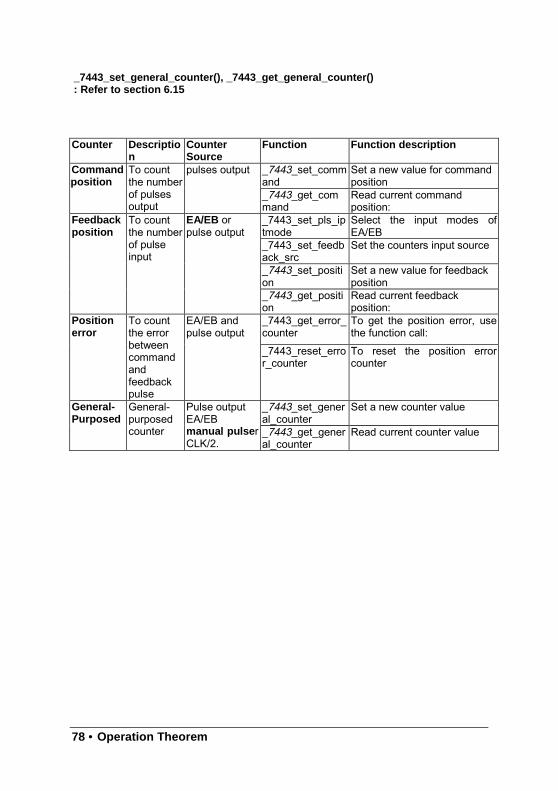
78 • Operation Theorem
_7443_set_general_counter(), _7443_get_general_counter(): Refer to section 6.15
Counter Description
CounterSource
Function Function description
_7443_set_command
Set a new value for commandposition
Commandposition
To countthe numberof pulsesoutput
pulses output
_7443_get_command
Read current commandposition:
_7443_set_pls_iptmode
Select the input modes ofEA/EB
_7443_set_feedback_src
Set the counters input source
_7443_set_position
Set a new value for feedbackposition
Feedbackposition
To countthe numberof pulseinput
EA/EB orpulse output
_7443_get_position
Read current feedbackposition:
_7443_get_error_counter
To get the position error, usethe function call:
Positionerror
To countthe errorbetweencommandandfeedbackpulse
EA/EB andpulse output
_7443_reset_error_counter
To reset the position errorcounter
_7443_set_general_counter
Set a new counter valueGeneral-Purposed
General-purposedcounter
Pulse outputEA/EBmanual pulse rCLK/2.
_7443_get_general_counter
Read current counter value
Operation Theorem • 79
4.4.5 Target position recorder
The target position recorder is very useful for providing target positioninformation. For example, if the PPCI7443 is operating in continuous motionwith absolute mode, the target position let next absolute motion knows thetarget position of previous one.
It is very important to know that the target position recorder is handled bysoftware. Every time when a new motion command is executed, thedisplacement is added automatically into the target position recorder. Tomake sure the correctness of target position recorder, user needs tomanually maintain it in the following two situations by the function call_7443_reset_target_pos() :
1. After Home move complete2. After new feedback position is set
Relative Functions:_7443_reset_target_pos(): Refer to section 6.15
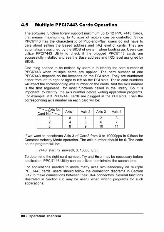
80 • Operation Theorem
4.5 Multiple PPCI7443 Cards Operation
The software function library support maximum up to 12 PPCI7443 Cards,that means maximum up to 48 axes of motors can be controlled. SincePPCI7443 has the characteristic of Plug-and-Play, users do not have tocare about setting the Based address and IRQ level of cards. They areautomatically assigned by the BIOS of system when booting up. Users canutilize PPCI7443 Utility to check if the plugged PPCI7443 cards aresuccessfully installed and see the Base address and IRQ level assigned byBIOS.
One thing needed to be noticed by users is to identify the card number ofPPCI7443 when multiple cards are applied. The card number of onePPCI7443 depends on the locations on the PCI slots. They are numberedeither from left to right or right to left on the PCI slots. These card numberswill effect the corresponding axis number on the cards. And the axis numberis the first argument for most functions called in the library. So it isimportant to identify the axis number before writing application programs.For example, if 3 PPCI7443 cards are plugged in the PCI slots. Then thecorresponding axis number on each card will be:
Axis No.Card No. Axis 1 Axis 2 Axis 3 Axis 4
1 0 1 2 32 4 5 6 73 8 9 10 11
If we want to accelerate Axis 3 of Card2 from 0 to 10000pps in 0.5sec forConstant Velocity Mode operation. The axis number should be 6. The codeon the program will be:
_7443_start_tv_move(6, 0, 10000, 0.5);
To determine the right card number, Try and Error may be necessary beforeapplication. PPCI7443 Utility can be utilized to minimize the search time.
For applications needed to move many axes simultaneously on multiplePCI_7443 cards, users should follow the connection diagrams in Section3.12 to make connections between their CN4 connectors. Several functionsillustrated in Section 6.8 may be useful when writing programs for suchapplications.
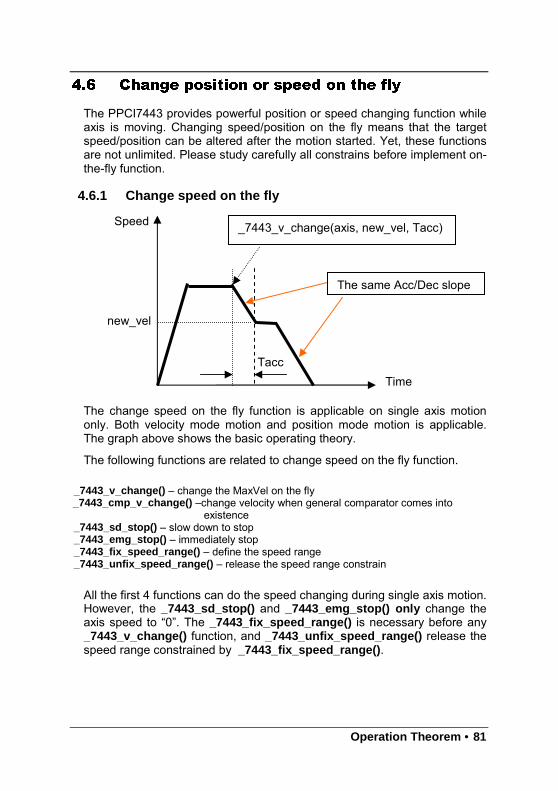
Operation Theorem • 81
4.6 Change position or speed on the fly
The PPCI7443 provides powerful position or speed changing function whileaxis is moving. Changing speed/position on the fly means that the targetspeed/position can be altered after the motion started. Yet, these functionsare not unlimited. Please study carefully all constrains before implement on-the-fly function.
4.6.1 Change speed on the fly
The change speed on the fly function is applicable on single axis motiononly. Both velocity mode motion and position mode motion is applicable.The graph above shows the basic operating theory.
The following functions are related to change speed on the fly function.
_7443_v_change() – change the MaxVel on the fly_7443_cmp_v_change() –change velocity when general comparator comes into
existence_7443_sd_stop() – slow down to stop_7443_emg_stop() – immediately stop_7443_fix_speed_range() – define the speed range_7443_unfix_speed_range() – release the speed range constrain
All the first 4 functions can do the speed changing during single axis motion.However, the _7443_sd_stop() and _7443_emg_stop() only change theaxis speed to “0”. The _7443_fix_speed_range() is necessary before any_7443_v_change() function, and _7443_unfix_speed_range() release thespeed range constrained by _7443_fix_speed_range() .
_7443_v_change(axis, new_vel, Tacc)
The same Acc/Dec slope
Tacc
new_vel
Time
Speed
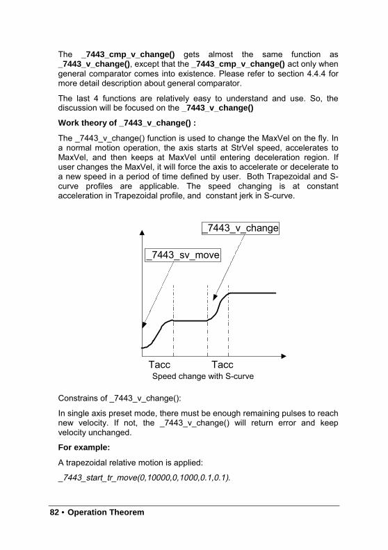
82 • Operation Theorem
The _7443_cmp_v_change() gets almost the same function as_7443_v_change(), except that the _7443_cmp_v_change() act only whengeneral comparator comes into existence. Please refer to section 4.4.4 formore detail description about general comparator.
The last 4 functions are relatively easy to understand and use. So, thediscussion will be focused on the _7443_v_change()
Work theory of _7443_v_change() :
The _7443_v_change() function is used to change the MaxVel on the fly. Ina normal motion operation, the axis starts at StrVel speed, accelerates toMaxVel, and then keeps at MaxVel until entering deceleration region. Ifuser changes the MaxVel, it will force the axis to accelerate or decelerate toa new speed in a period of time defined by user. Both Trapezoidal and S-curve profiles are applicable. The speed changing is at constantacceleration in Trapezoidal profile, and constant jerk in S-curve.
Speed change with S-curve
Constrains of _7443_v_change():
In single axis preset mode, there must be enough remaining pulses to reachnew velocity. If not, the _7443_v_change() will return error and keepvelocity unchanged.
For example:
A trapezoidal relative motion is applied:
_7443_start_tr_move(0,10000,0,1000,0.1,0.1).
_7443_sv_move
_7443_v_change
TaccTacc
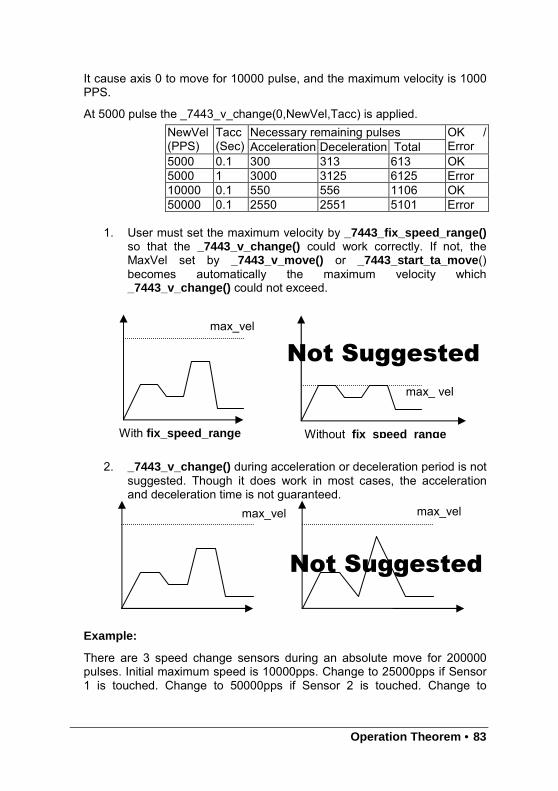
Operation Theorem • 83
It cause axis 0 to move for 10000 pulse, and the maximum velocity is 1000PPS.
At 5000 pulse the _7443_v_change(0,NewVel,Tacc) is applied.Necessary remaining pulsesNewVel
(PPS)Tacc(Sec) Acceleration Deceleration Total
OK /Error
5000 0.1 300 313 613 OK5000 1 3000 3125 6125 Error10000 0.1 550 556 1106 OK50000 0.1 2550 2551 5101 Error
1. User must set the maximum velocity by _7443_fix_speed_range()so that the _7443_v_change() could work correctly. If not, theMaxVel set by _7443_v_move() or _7443_start_ta_move()becomes automatically the maximum velocity which_7443_v_change() could not exceed.
2. _7443_v_change() during acceleration or deceleration period is notsuggested. Though it does work in most cases, the accelerationand deceleration time is not guaranteed.
Example:
There are 3 speed change sensors during an absolute move for 200000pulses. Initial maximum speed is 10000pps. Change to 25000pps if Sensor1 is touched. Change to 50000pps if Sensor 2 is touched. Change to
max_vel max_vel
Not Suggested
max_vel
With fix_speed_range
Not Suggested
max_ vel
Without fix s peed ran ge
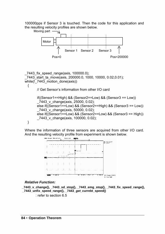
84 • Operation Theorem
100000pps if Sensor 3 is touched. Then the code for this application andthe resulting velocity profiles are shown below.
_7443_fix_speed_range(axis, 100000.0);_7443_start_ta_move(axis, 200000.0, 1000, 10000, 0.02,0.01);while(!_7443_motion_done(axis))
// Get Sensor’s information from other I/O card
if((Sensor1==High) && (Sensor2==Low) && (Sensor3 == Low))_7443_v_change(axis, 25000, 0.02);else if((Sensor1==Low) && (Sensor2==High) && (Sensor3 == Low))_7443_v_change(axis, 50000, 0.02);else if((Sensor1==Low) && (Sensor2==Low) && (Sensor3 == High))_7443_v_change(axis, 100000, 0.02);
Where the information of three sensors are acquired from other I/O card.And the resulting velocity profile from experiment is shown below.
Relative Function:_7443_v_change(), _7443_sd_stop(), _7443_emg_stop(), _7443 _fix_speed_range(),_7443_unfix_speed_range(), _7443 _get_currebt_speed()
: refer to section 6.5
Motor
Sensor 2 Sensor 3
Pos=0 Pos=200000
Moving part
Sensor 1
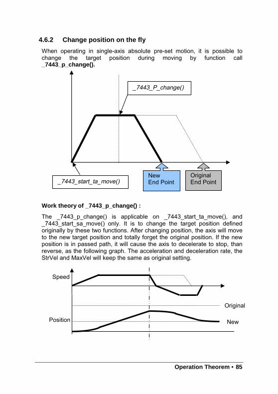
Operation Theorem • 85
4.6.2 Change position on the fly
When operating in single-axis absolute pre-set motion, it is possible tochange the target position during moving by function call_7443_p_change().
Work theory of _7443_p_change() :
The _7443_p_change() is applicable on _7443_start_ta_move(), and_7443_start_sa_move() only. It is to change the target position definedoriginally by these two functions. After changing position, the axis will moveto the new target position and totally forget the original position. If the newposition is in passed path, it will cause the axis to decelerate to stop, thanreverse, as the following graph. The acceleration and deceleration rate, theStrVel and MaxVel will keep the same as original setting.
Speed
Position
Original
New
_7443_P_change()
_7443_start_ta_move()OriginalEnd Point
NewEnd Point
86 • Operation Theorem
Constrains of _7443_p_change() :
1. _7443_p_change() is only applicable on single-axis absolute pre-setmotion, ie, _7443_start_ta_move() , and _7443_start_sa_move() only
2. Position change on deceleration period is not allowed.
3. There must be enough distance between new target position and currentposition where _7443_p_change() is executed. Because, PPCI7443needs enough space to finish deceleration.
For example:
A trapezoidal absolute motion is applied:
_7443_start_ta_move(0,10000,0,1000,0.5,1).
It cause axis 0 to move to pulse 10000 position, and the maximum velocityis 1000 PPS. The necessary number of pulses to decelerate is 0.5*1000*1= 500.
At position “CurrentPos” the _7443_p_change(0, NewPos) is applied.
Relative Function:_7443_p_change() : refer to section 6.6
NewPos CurrentPos OK / Error Note
5000 4000 OK5000 4501 Error5000 5000 Error5000 5499 Error5000 6000 OK Go back5000 9499 OK Go back5000 9500 Error5000 9999 Error
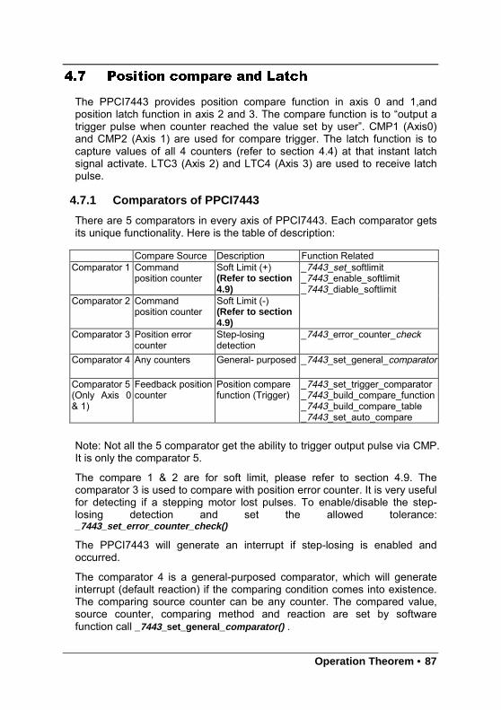
Operation Theorem • 87
4.7 Position compare and Latch
The PPCI7443 provides position compare function in axis 0 and 1,andposition latch function in axis 2 and 3. The compare function is to “output atrigger pulse when counter reached the value set by user”. CMP1 (Axis0)and CMP2 (Axis 1) are used for compare trigger. The latch function is tocapture values of all 4 counters (refer to section 4.4) at that instant latchsignal activate. LTC3 (Axis 2) and LTC4 (Axis 3) are used to receive latchpulse.
4.7.1 Comparators of PPCI7443
There are 5 comparators in every axis of PPCI7443. Each comparator getsits unique functionality. Here is the table of description:
Note: Not all the 5 comparator get the ability to trigger output pulse via CMP.It is only the comparator 5.
The compare 1 & 2 are for soft limit, please refer to section 4.9. Thecomparator 3 is used to compare with position error counter. It is very usefulfor detecting if a stepping motor lost pulses. To enable/disable the step-losing detection and set the allowed tolerance:_7443_set_error_counter_check()
The PPCI7443 will generate an interrupt if step-losing is enabled andoccurred.
The comparator 4 is a general-purposed comparator, which will generateinterrupt (default reaction) if the comparing condition comes into existence.The comparing source counter can be any counter. The compared value,source counter, comparing method and reaction are set by softwarefunction call _7443_set_general _comparator() .
Compare Source Description Function RelatedComparator 1 Command
position counterSoft Limit (+)(Refer to section4.9)
Comparator 2 Commandposition counter
Soft Limit (-)(Refer to section4.9)
_7443_set_softlimit_7443_enable_softlimit_7443_diable_softlimit
Comparator 3 Position errorcounter
Step-losingdetection
_7443_error_counter_check
Comparator 4 Any counters General- purposed _7443_set_general_comparator
Comparator 5(Only Axis 0& 1)
Feedback positioncounter
Position comparefunction (Trigger)
_7443_set_trigger_comparator_7443_build_compare_function_7443_build_compare_table_7443_set_auto_compare
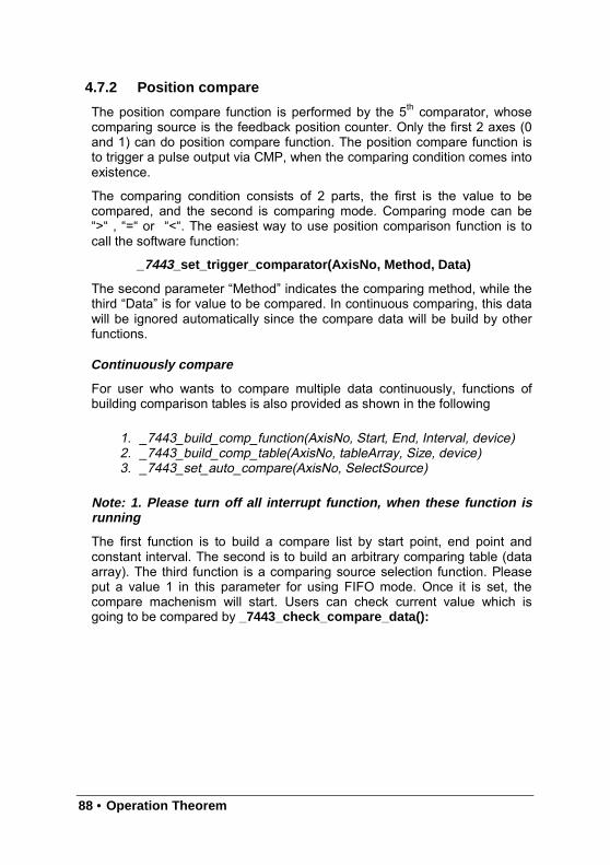
88 • Operation Theorem
4.7.2 Position compare
The position compare function is performed by the 5th comparator, whosecomparing source is the feedback position counter. Only the first 2 axes (0and 1) can do position compare function. The position compare function isto trigger a pulse output via CMP, when the comparing condition comes intoexistence.
The comparing condition consists of 2 parts, the first is the value to becompared, and the second is comparing mode. Comparing mode can be“>“ , “=“ or “<“. The easiest way to use position comparison function is tocall the software function:
_7443_set_trigger_comparator(AxisNo, Method, Data)
The second parameter “Method” indicates the comparing method, while thethird “Data” is for value to be compared. In continuous comparing, this datawill be ignored automatically since the compare data will be build by otherfunctions.
Continuously compare
For user who wants to compare multiple data continuously, functions ofbuilding comparison tables is also provided as shown in the following
1. _7443_build_comp_function(AxisNo, Start, End, Interval, device)2. _7443_build_comp_table(AxisNo, tableArray, Size, device)3. _7443_set_auto_compare(AxisNo, SelectSource)
Note: 1. Please turn off all interrupt function, when these function isrunning
The first function is to build a compare list by start point, end point andconstant interval. The second is to build an arbitrary comparing table (dataarray). The third function is a comparing source selection function. Pleaseput a value 1 in this parameter for using FIFO mode. Once it is set, thecompare machenism will start. Users can check current value which isgoing to be compared by _7443_check_compare_data():
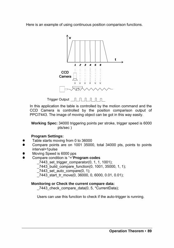
Operation Theorem • 89
Here is an example of using continuous position comparison functions.
In this application the table is controlled by the motion command and theCCD Camera is controlled by the position comparison output ofPPCI7443. The image of moving object can be got in this way easily.
Working Spec: 34000 triggering points per stroke, trigger speed is 6000pts/sec )
Program Settings:
Table starts moving from 0 to 36000 Compare points are on 1001 35000, total 34000 pts, points to points
interval=1pulse Moving Speed is 6000 pps Compare condition is “=“Program codes
_7443_set_trigger_comparator(0, 1, 1, 1001);_7443_build_compare_function(0, 1001, 35000, 1, 1);_7443_set_auto_compare(0, 1);_7443_start_tr_move(0, 36000, 0, 6000, 0.01, 0.01);
Monitoring or Check the current compare data:_7443_check_compare_data(0, 5, *CurrentData);
Users can use this function to check if the auto-trigger is running.
t
v
1 2 3 4 5 6
CCDCamera
t
v
1 2 3 4 5 6
CCDCamera
Trigger Output
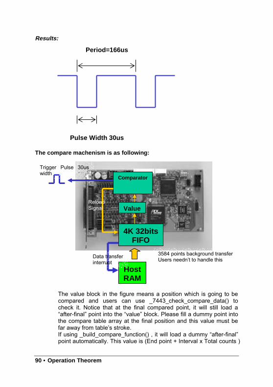
90 • Operation Theorem
Pulse Width 30us
Period=166us
Results:
The compare machenism is as following:
The value block in the figure means a position which is going to becompared and users can use _7443_check_compare_data() tocheck it. Notice that at the final compared point, it will still load a“after-final” point into the “value” block. Please fill a dummy point intothe compare table array at the final position and this value must befar away from table’s stroke.If using _build_compare_function() , it will load a dummy “after-final”point automatically. This value is (End point + Interval x Total counts )
Comparator
Value
4K 32bitsFIFO
HostRAM
Data transferinterrupt
ReloadSignal
Trigger Pulse 30uswidth
3584 points background transferUsers needn’t to handle this
Operation Theorem • 91
x moving ratio.
Relative Function:_7443_set_trigger_comparator(), _7443_build_comp_function(),_7443_build_comp_table(), _7443_set_auto_compare(),_7443_check_compare_data(),_7443_set_trigger_type ()
: refer to section 6.16
4.7.3 Position Latch
Position latch is a contrary function to position compare. The positioncompare function is to trigger a pulse output via CMP, when the comparingcondition comes into existence. Yet, the position latch function is to receivepulse input via LTC, and then capture all counters’ (refer to section 4.4)data in that instant. The latency between occurring of latch signal andfinishing of position capturing is extremely short, for the latching procedureis made by hardware. Only the last 2 axes (2 and 3) can do position latchfunction. LTC3 (Axis 2) and LTC4 (Axis 3) are used to receive latch pulse.
To set the latch logic: _7443_set_ltc_logic().
To get the latched values of counters: _7443_get_latch_data(AxisNo,CntNo, Pos). The second parameter “CntNo” is used to indicate thecounter of which the latched data will be read. And, it can latched evenexcept for the LTC pin by the _7443_set_enable_inp() command.
Relative Function:_7443_set_ltc_logic(),_7443_get_latch_data() : refer to section 6.16
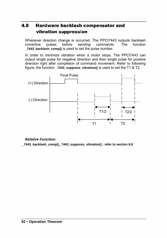
92 • Operation Theorem
4.8 Hardware backlash compensator and
vibration suppression
Whenever direction change is occurred, The PPCI7443 outputs backlashcorrective pulses before sending commands. The function_7443_backlash_comp() is used to set the pulse number.
In order to minimize vibration when a motor stops. The PPCI7443 canoutput single pulse for negative direction and then single pulse for positivedirection right after completion of command movement. Refer to followingfigure, the function _7443_suppress_vibration() is used to set the T1 & T2.
Relative Function:_7443_backlash_comp(),_7443_suppress_vibration() : refer to section 6.6
(+) Direction
(-) Direction
Final Pulse
T1 T2
T1/2 T2/2
Operation Theorem • 93
4.9 Software Limit Function
The PPCI7443 provides 2 software limits for each axis. The soft limit isextremely useful to protect user’s mechanical system, for it works as aphysical limit switch, when setting correctly.
The soft limit is built on comparator 1 and 2 (please refer to section 4.7.1),and the comparing source is command position counter. The working theoryis that pre-setting limits value on comparator 1 and 2, then, when thecommand position counter reached the limit value, the PPCI7443 reacts asthe physical limit switch is touched. Thus, it stops immediately ordecelerates to stop pulse output.To set the soft limit: _7443_set_softlimit();To enable soft limit: _7443_enable _softlimit();To disable soft limit: _7443_diable _softlimit()
Note: The soft limit is applied to command position , but not the feedbackposition (please refer to 4.4). In case the moving ratio is not equal to “1”, itis necessary for user to manually calculate the corresponding commandposition where the soft limit is, when using _7443_set_softlimit() .
Relative Function:_7443_set_softlimit(),_7443_enable_softlimit(), _7443_diable_softlimit()
: refer to section 6.16
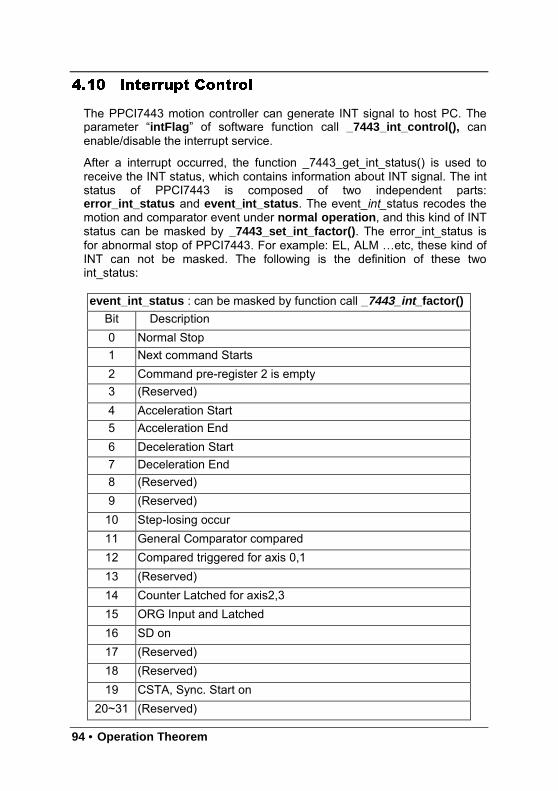
94 • Operation Theorem
4.10 Interrupt Control
The PPCI7443 motion controller can generate INT signal to host PC. Theparameter “intFlag ” of software function call _7443_int_control(), canenable/disable the interrupt service.
After a interrupt occurred, the function _7443_get_int_status() is used toreceive the INT status, which contains information about INT signal. The intstatus of PPCI7443 is composed of two independent parts:error_int_status and event_int_status. The event_ int_status recodes themotion and comparator event under normal operation , and this kind of INTstatus can be masked by _7443_set_int_factor() . The error_int_status isfor abnormal stop of PPCI7443. For example: EL, ALM …etc, these kind ofINT can not be masked. The following is the definition of these twoint_status:
event_int_status : can be masked by function call _7443_int_ factor()
Bit Description0 Normal Stop1 Next command Starts2 Command pre-register 2 is empty3 (Reserved)4 Acceleration Start5 Acceleration End6 Deceleration Start7 Deceleration End8 (Reserved)9 (Reserved)10 Step-losing occur11 General Comparator compared12 Compared triggered for axis 0,113 (Reserved)14 Counter Latched for axis2,315 ORG Input and Latched16 SD on17 (Reserved)18 (Reserved)19 CSTA, Sync. Start on
20~31 (Reserved)
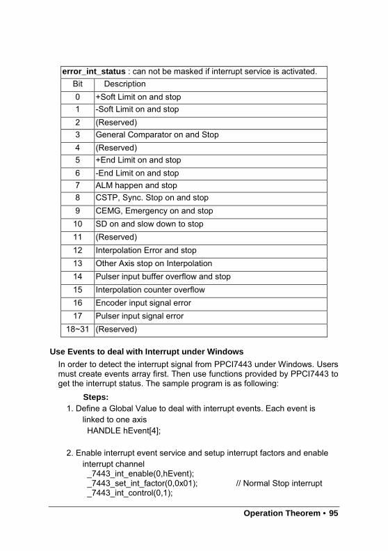
Operation Theorem • 95
Use Events to deal with Interrupt under Windows
In order to detect the interrupt signal from PPCI7443 under Windows. Usersmust create events array first. Then use functions provided by PPCI7443 toget the interrupt status. The sample program is as following:
Steps:1. Define a Global Value to deal with interrupt events. Each event is
linked to one axisHANDLE hEvent[4];
2. Enable interrupt event service and setup interrupt factors and enableinterrupt channel_7443_int_enable(0,hEvent);_7443_set_int_factor(0,0x01); // Normal Stop interrupt_7443_int_control(0,1);
error_int_status : can not be masked if interrupt service is activated.Bit Description0 +Soft Limit on and stop1 -Soft Limit on and stop2 (Reserved)3 General Comparator on and Stop4 (Reserved)5 +End Limit on and stop6 -End Limit on and stop7 ALM happen and stop8 CSTP, Sync. Stop on and stop9 CEMG, Emergency on and stop10 SD on and slow down to stop11 (Reserved)12 Interpolation Error and stop13 Other Axis stop on Interpolation14 Pulser input buffer overflow and stop15 Interpolation counter overflow16 Encoder input signal error17 Pulser input signal error
18~31 (Reserved)
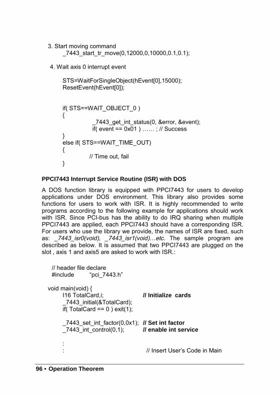
96 • Operation Theorem
3. Start moving command_7443_start_tr_move(0,12000,0,10000,0.1,0.1);
4. Wait axis 0 interrupt event
STS=WaitForSingleObject(hEvent[0],15000);ResetEvent(hEvent[0]);
if( STS==WAIT_OBJECT_0 )
_7443_get_int_status(0, &error, &event);if( event == 0x01 ) …… ; // Success
else if( STS==WAIT_TIME_OUT)
// Time out, fail
PPCI7443 Interrupt Service Routine (ISR) with DOS
A DOS function library is equipped with PPCI7443 for users to developapplications under DOS environment. This library also provides somefunctions for users to work with ISR. It is highly recommended to writeprograms according to the following example for applications should workwith ISR. Since PCI-bus has the ability to do IRQ sharing when multiplePPCI7443 are applied, each PPCI7443 should have a corresponding ISR.For users who use the library we provide, the names of ISR are fixed, suchas: _7443_isr0(void), _7443_isr1(void)…etc. The sample program aredescribed as below. It is assumed that two PPCI7443 are plugged on theslot , axis 1 and axis5 are asked to work with ISR.:
// header file declare#include “pci_7443.h”
void main(void) I16 TotalCard,i; // Initialize cards_7443_initial(&TotalCard);if( TotalCard == 0 ) exit(1);
_7443_set_int_factor(0,0x1); // Set int factor_7443_int_control(0,1); // enable int service
:: // Insert User’s Code in Main
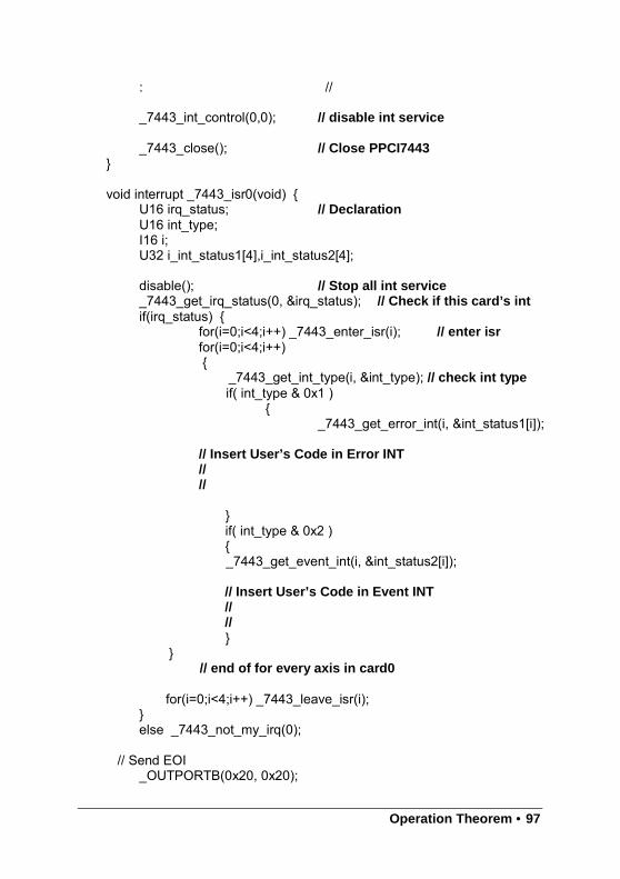
Operation Theorem • 97
: //
_7443_int_control(0,0); // disable int service
_7443_close(); // Close PPCI7443
void interrupt _7443_isr0(void) U16 irq_status; // DeclarationU16 int_type;I16 i;U32 i_int_status1[4],i_int_status2[4];
disable(); // Stop all int service_7443_get_irq_status(0, &irq_status); // Check if this card’s intif(irq_status)
for(i=0;i<4;i++) _7443_enter_isr(i); // enter isrfor(i=0;i<4;i++)
_7443_get_int_type(i, &int_type); // check int typeif( int_type & 0x1 )
_7443_get_error_int(i, &int_status1[i]);
// Insert User’s Code in Error INT////
if( int_type & 0x2 )_7443_get_event_int(i, &int_status2[i]);
// Insert User’s Code in Event INT////
// end of for every axis in card0
for(i=0;i<4;i++) _7443_leave_isr(i);else _7443_not_my_irq(0);
// Send EOI_OUTPORTB(0x20, 0x20);
98 • Operation Theorem
_OUTPORTB(0xA0, 0x20);enable(); // allow int service
void interrupt _7443_isr1(void)void interrupt _7443_isr2(void)void interrupt _7443_isr3(void)void interrupt _7443_isr4(void)void interrupt _7443_isr5(void)void interrupt _7443_isr6(void)void interrupt _7443_isr7(void)void interrupt _7443_isr8(void)void interrupt _7443_isr9(void)void interrupt _7443_isra(void)void interrupt _7443_isrb(void)
So with the sample, user can get the interrupt signal about each axis in themotion control system.
Relative Function:_7443_int_control(), _7443_set_int_factor(), _7443_int_enable(),_7443_int_disable(), _7443_get_int_status(), _7443_link_interrupt(),_7443_get_int_type(), _7443_enter_isr(), _7443_leave_isr()_7443_get_event_int(), _7443_get_error_int(), _7443_get_irq_status()_7443_not_my_irq(), _7443_isr0~9, a, b
: refer to section 6.14
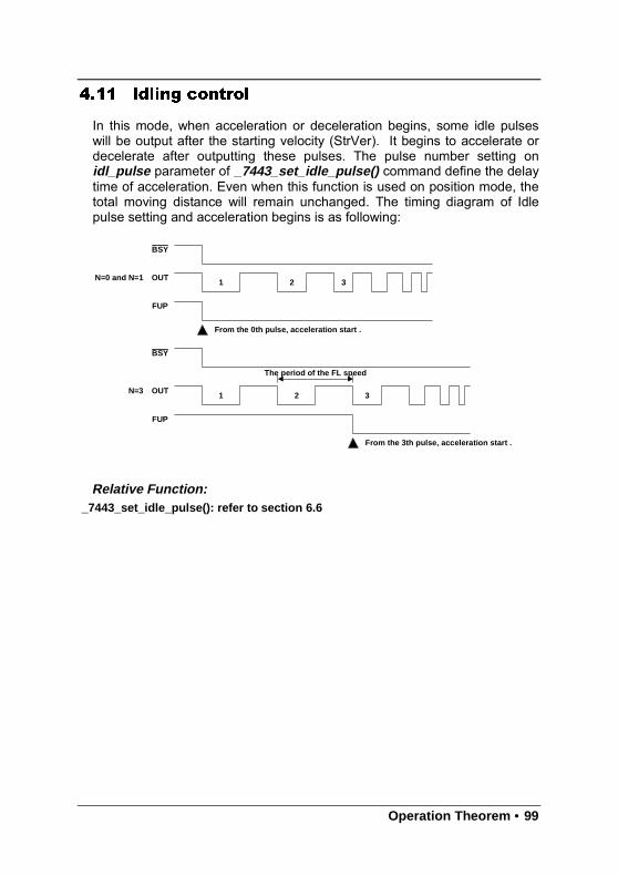
Operation Theorem • 99
4.11 Idling control
In this mode, when acceleration or deceleration begins, some idle pulseswill be output after the starting velocity (StrVer). It begins to accelerate ordecelerate after outputting these pulses. The pulse number setting onidl_pulse parameter of _7443_set_idle_pulse() command define the delaytime of acceleration. Even when this function is used on position mode, thetotal moving distance will remain unchanged. The timing diagram of Idlepulse setting and acceleration begins is as following:
Relative Function:_7443_set_idle_pulse(): refer to section 6.6
BSY
OUT1 2 3
FUP
From the 0th pulse, acceleration start .
BSY
OUT1 2 3
FUP
From the 3th pulse, acceleration start .
The period of the FL speed
N=0 and N=1
N=3


PPCI7443 Utility • 101
5
PPCI7443 Utility
After installing all the hardware properly according to Chapter 2 and 3, it isnecessary to correctly configure cards and double check before running.This chapter gives guidelines for establishing a control system andmanually exercising the PPCI7443 cards to verify correct operation.PPCI7443 Utility provides a simple yet powerful means to setup, configure,test and debug motion control system that uses PPCI7443 cards.
Note that PPCI7443 Utility is available only for Windows 95/98 or WindowsNT/2000/XP with the screen resolution higher than 800x600 environmentand can not run on DOS.
102 • PPCI7443 Utility
5.1 Execute PPCI7443 Utility
After installing the software driver of PPCI7443 on Windows95/98/NT/2000/XP, the PPCI7443 Utility program can be find in <chosenpath >/ PPCI7443/Utility. To execute it, double click it or use desktop “Start” “Program files” “PPCI7443” “PPCI7443 Utility”.
5.2 About PPCI7443 Utility
Before Running PPCI7443 Utility for PPCI7443, the following issues shouldbe kept in mind.
1. PPCI7443 Utility is a program written by VB 5.0, and is available only forWindows with the screen resolution higher than 800x600 environment. Itcan not run on DOS.
2. PPCI7443 Utility allows users to save settings or configurations forPPCI7443 cards and those saved configurations will be loadedautomatically when PPCI7443 Utility is executed later again. The two files7443.ini and 7443MC.ini in windows root directory are used to save allsettings and configurations.
3. To duplicate configurations from one system to another system, just copy7443.ini and 7443MC.ini into windows root directory.
4. If users want to use the configurations set by PPCI7443 Utility, the DLLfunction call _7443_config_from_file() is helpful. After calling thisfunction in user’s program, user can use those PPCI7443 cards as thesame configuration as set by PPCI7443 Utility.
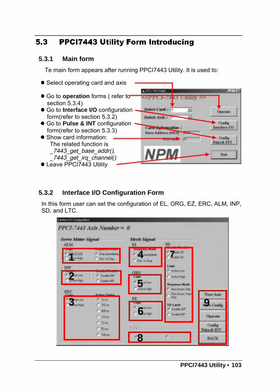
PPCI7443 Utility • 103
5.3 PPCI7443 Utility Form Introducing
5.3.1 Main form
Te main form appears after running PPCI7443 Utility. It is used to:
5.3.2 Interface I/O Configuration Form
In this form user can set the configuration of EL, ORG, EZ, ERC, ALM, INP,SD, and LTC.
Select operating card and axis
Go to operation forms ( refer tosection 5.3.4)
Go to Interface I/O configurationform(refer to section 5.3.2)
Go to Pulse & INT configurationform(refer to section 5.3.3)
Show card information:The related function is_7443_get_base_addr(),_7443_get_irq_channel()
Leave PPCI7443 Utility
1
2
3
4
5
6
7
8
9
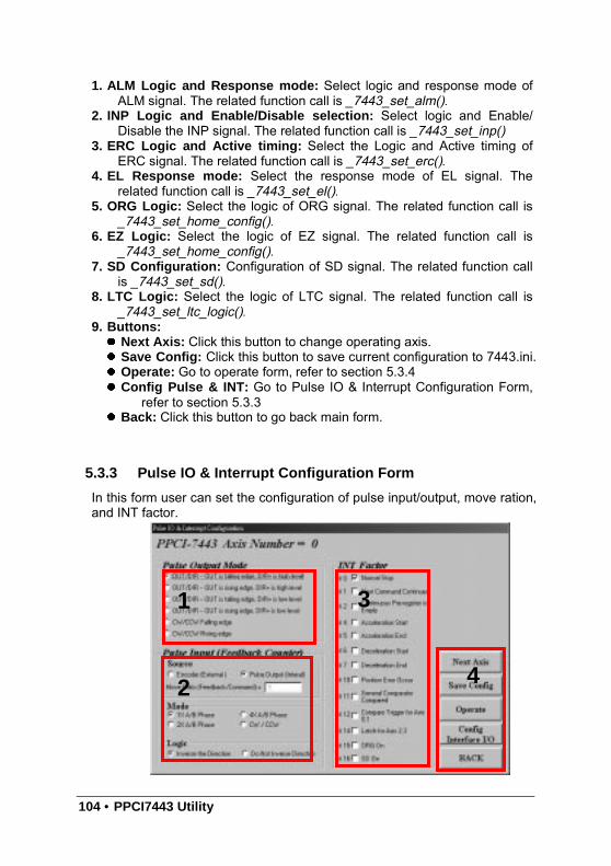
104 • PPCI7443 Utility
1. ALM Logic and Response mode: Select logic and response mode ofALM signal. The related function call is _7443_set_alm().
2. INP Logic and Enable/Disable selection: Select logic and Enable/Disable the INP signal. The related function call is _7443_set_inp()
3. ERC Logic and Active timing: Select the Logic and Active timing ofERC signal. The related function call is _7443_set_erc().
4. EL Response mode: Select the response mode of EL signal. Therelated function call is _7443_set_el().
5. ORG Logic: Select the logic of ORG signal. The related function call is_7443_set_home_config().
6. EZ Logic: Select the logic of EZ signal. The related function call is_7443_set_home_config().
7. SD Configuration: Configuration of SD signal. The related function callis _7443_set_sd().
8. LTC Logic: Select the logic of LTC signal. The related function call is_7443_set_ltc_logic().
9. Buttons: Next Axis: Click this button to change operating axis. Save Config: Click this button to save current configuration to 7443.ini. Operate: Go to operate form, refer to section 5.3.4 Config Pulse & INT: Go to Pulse IO & Interrupt Configuration Form,
refer to section 5.3.3 Back: Click this button to go back main form.
5.3.3 Pulse IO & Interrupt Configuration Form
In this form user can set the configuration of pulse input/output, move ration,and INT factor.
1
2
3
4
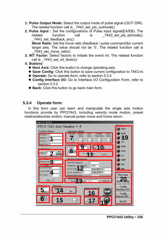
PPCI7443 Utility • 105
1. Pulse Output Mode: Select the output mode of pulse signal (OUT/ DIR).The related function call is _7443_set_pls_outmode().
2. Pulse Input : Set the configurations of Pulse input signal(EA/EB). Therelated function call is _7443_set_pls_iptmode(),_7443_set_feedback_src().Move Ratio: Set the move ratio (feedback / pulse command)for currenttarget axis. The value should not be ‘0’. The related function call is_7443_set_move_ratio().
3. INT Factor: Select factors to initiate the event int. The related functioncall is _7443_set_int_factor().
4. Buttons: Next Axis: Click this button to change operating axis. Save Config: Click this button to save current configuration to 7443.ini. Operate: Go to operate form, refer to section 5.3.4 Config Interface I/O: Go to Interface I/O Configuration Form, refer to
section 5.3.2 Back: Click this button to go back main form.
5.3.4 Operate form:In this form user can learn and manipulate the single axis motion
functions provide by PPCI7443, including velocity mode motion, presetrelative/absolute motion, manual pulser move and home return.
1
23
4
56
14
15
7
89 10
11
12
13
16
18
19
20
17
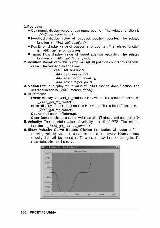
106 • PPCI7443 Utility
1.Position:Command: display value of command counter. The related function is
_7443_get_command(). Feedback: display value of feedback position counter. The related
function is _7443_get_position() Pos Error: display value of position error counter. The related function
is _7443_get_error_counter(). Target Pos: display value of target position recorder. The related
function is _7443_get_target_pos().2. Position Reset: click this button will set all position counter to specified
value. The related functions are:_7443_set_position(),_7443_set_command(),_7443_reset_error_counter()_7443_reset_target_pos()
3. Motion Status: display return value of _7443_motion_done function. Therelated function is _7443_motion_done().
4. INT Status:Event : display of event_int_status in Hex value. The related function is
_7443_get_int_status().Error : display of error_int_status in Hex value. The related function is
_7443_get_int_status().Count : total count of interrupt.Clear Button: click this button will clear all INT status and counter to ‘0’.
5. Velocity: The absolute value of velocity in unit of PPS. The relatedfunction is _7443_get_current_speed().
6. Show Velocity Curve Button: Clicking this button will open a formshowing velocity vs. time curve. In this curve, every 100ms a newvelocity data will be added in. To close it, click this button again. Toclear data, click on the curve.
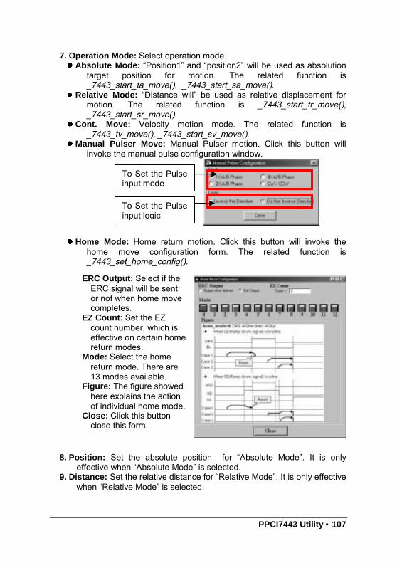
PPCI7443 Utility • 107
7. Operation Mode: Select operation mode. Absolute Mode: “Position1” and “position2” will be used as absolution
target position for motion. The related function is_7443_start_ta_move(), _7443_start_sa_move().
Relative Mode: “Distance will” be used as relative displacement formotion. The related function is _7443_start_tr_move(),_7443_start_sr_move().
Cont. Move: Velocity motion mode. The related function is_7443_tv_move(), _7443_start_sv_move().
Manual Pulser Move: Manual Pulser motion. Click this button willinvoke the manual pulse configuration window.
Home Mode: Home return motion. Click this button will invoke thehome move configuration form. The related function is_7443_set_home_config().
8. Position: Set the absolute position for “Absolute Mode”. It is onlyeffective when “Absolute Mode” is selected.
9. Distance: Set the relative distance for “Relative Mode”. It is only effectivewhen “Relative Mode” is selected.
To Set the Pulseinput mode
To Set the Pulseinput logic
ERC Output: Select if theERC signal will be sentor not when home movecompletes.
EZ Count: Set the EZcount number, which iseffective on certain homereturn modes.
Mode: Select the homereturn mode. There are13 modes available.
Figure: The figure showedhere explains the actionof individual home mode.
Close: Click this buttonclose this form.
108 • PPCI7443 Utility
10. Repeat Mode: When “On” is selected, the motion will go in repeatmode(forward backward or position1 position2 ). It is onlyeffective when “Relative Mode” or “Absolute Mode” is selected.
11. Vel. Profile: Select the velocity profile. Both Trapezoidal and S-curveare available for “Absolute Mode”, “Relative Mode” and “Cont. Move”.
12. Motion Parameters: Set the parameters for single axis motion. Theseparameter is meaningless if “Manual Pulser Move” is selected, sincethe velocity and moving distance is decided by pulse input. Start Velocity: Set the start velocity of motion in unit of PPS. In
“Absolute Mode” or “Relative Mode”, only the value is effective.ie, -100.0 is the same as 100.0. In “Cont. Move”, both the valueand sing is effective. –100.0 means 100.0 in minus direction.
Maximum Velocity: Set the maximum velocity of motion in unit ofPPS. In “Absolute Mode” or “Relative Mode”, only the value iseffective. ie, -5000.0 is the same as 5000.0. In “Cont. Move”,both the value and sing is effective. –5000.0 means 5000.0 inminus direction.
Accel. Time :Set the acceleration time in unit of second. Decel. Time :Set the deceleration time in unit of second. SVacc: Set the S-curve range during acceleration in unit of PPS. SVdec: Set the S-curve range during deceleration in unit of PPS. Move Delay : This setting is effective only when repeat mode is set
“On”. It will cause PPCI7443 to delay specified time before itcontinue next motion.
13. Speed Range: Set the max speed of motion. If “Not Fix” is selected,the “Maximum Speed” will automatically become the maximum speedrange, which can not be exceeded by on-the-fly velocity change.
14. Servo On: Set the SVON signal output status. The related function is_7443_set_servo().
15. Play Key:Left play button: Click this button will cause PPCI7443 start to outletpulses according to previous setting.In “Absolute Mode”, it cause axis move to position1.In “Relative Mode”, it cause axis move forward.In “Cont. Move”, it cause axis start to move according to the
velocity setting.In “Manual Pulser Move”, it cause axis get into pulser move. The
speed limit is the value set by “Maximum Velocity”Right play button: Click this button will cause PPCI7443 start to outletpulses according to previous setting.In “Absolute Mode”, it cause axis move to position2.In “Relative Mode”, it cause axis move backward.In “Cont. Move”, it cause axis start to move according to the
velocity setting, but the other direction.In “Manual Pulser Move”, it cause axis get into pulser move. The
speed limit is the value set by “Maximum Velocity”
PPCI7443 Utility • 109
16. Change Position On The Fly Button: When this button is enabled,users can change the target position of current motion. The newposition must be defined in “Position2”. The related function is_7443_p_change().
17. Change Velocity On The Fly Button: When this button is enabled,users can change the velocity of current motion. The new velocity mustbe defined in “Maximum Velocity”. The related function is_7443_v_change()
18. Stop Button: Click this button will cause PPCI7443 to decelerate tostop. The deceleration time is defined in “Decel. Time”. The relatedfunction is _7443_sd_stop().
19. I/O Status: The status of motion I/O. Light-On means Active, whileLight-Off indicates inactive. The related function is_7443_get_io_status().
20. Buttons: Next Axis: Click this button to change operating axis. Save Config: Click this button to save current configuration to 7443.ini. Config Pulse & INT: Go to Pulse IO & Interrupt Configuration Form,
refer to section 5.3.3 Config Interface I/O: Go to Interface I/O Configuration Form, refer to
section 5.3.2 Back: Click this button to go back main form.

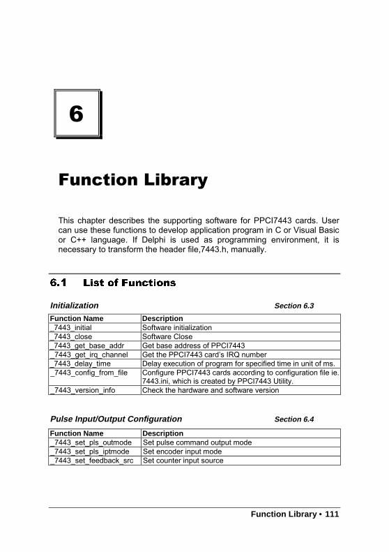
Function Library • 111
6
Function Library
This chapter describes the supporting software for PPCI7443 cards. Usercan use these functions to develop application program in C or Visual Basicor C++ language. If Delphi is used as programming environment, it isnecessary to transform the header file,7443.h, manually.
6.1 List of Functions
Initialization Section 6.3
Pulse Input/Output Configuration Section 6.4
Function Name Description_7443_initial Software initialization_7443_close Software Close_7443_get_base_addr Get base address of PPCI7443_7443_get_irq_channel Get the PPCI7443 card’s IRQ number_7443_delay_time Delay execution of program for specified time in unit of ms._7443_config_from_file Configure PPCI7443 cards according to configuration file ie.
7443.ini, which is created by PPCI7443 Utility._7443_version_info Check the hardware and software version
Function Name Description_7443_set_pls_outmode Set pulse command output mode_7443_set_pls_iptmode Set encoder input mode_7443_set_feedback_src Set counter input source
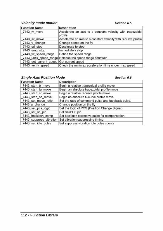
112 • Function Library
Velocity mode motion Section 6.5
Single Axis Position Mode Section 6.6
Function Name Description_7443_tv_move Accelerate an axis to a constant velocity with trapezoidal
profile_7443_sv_move Accelerate an axis to a constant velocity with S-curve profile_7443_v_change Change speed on the fly_7443_sd_stop Decelerate to stop_7443_emg_stop Immediately stop_7443_fix_speed_range Define the speed range_7443_unfix_speed_range Release the speed range constrain_7443_get_current_speed Get current speed_7443_verify_speed Check the min/max acceleration time under max speed
Function Name Description_7443_start_tr_move Begin a relative trapezoidal profile move_7443_start_ta_move Begin an absolute trapezoidal profile move_7443_start_sr_move Begin a relative S-curve profile move_7443_start_sa_move Begin an absolute S-curve profile move_7443_set_move_ratio Set the ratio of command pulse and feedback pulse._7443_p_change Change position on the fly_7443_set_pcs_logic Set the logic of PCS (Position Change Signal)_7443_set_sd_pin Set SD/PCS pin_7443_backlash_comp Set backlash corrective pulse for compensation_7443_suppress_vibration Set vibration suppressing timing_7443_set_idle_pulse Set suppress vibration idle pulse counts
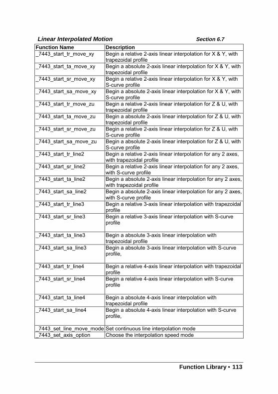
Function Library • 113
Linear Interpolated Motion Section 6.7
Function Name Description_7443_start_tr_move_xy Begin a relative 2-axis linear interpolation for X & Y, with
trapezoidal profile_7443_start_ta_move_xy Begin a absolute 2-axis linear interpolation for X & Y, with
trapezoidal profile_7443_start_sr_move_xy Begin a relative 2-axis linear interpolation for X & Y, with
S-curve profile_7443_start_sa_move_xy Begin a absolute 2-axis linear interpolation for X & Y, with
S-curve profile_7443_start_tr_move_zu Begin a relative 2-axis linear interpolation for Z & U, with
trapezoidal profile_7443_start_ta_move_zu Begin a absolute 2-axis linear interpolation for Z & U, with
trapezoidal profile_7443_start_sr_move_zu Begin a relative 2-axis linear interpolation for Z & U, with
S-curve profile_7443_start_sa_move_zu Begin a absolute 2-axis linear interpolation for Z & U, with
S-curve profile_7443_start_tr_line2 Begin a relative 2-axis linear interpolation for any 2 axes,
with trapezoidal profile_7443_start_sr_line2 Begin a relative 2-axis linear interpolation for any 2 axes,
with S-curve profile_7443_start_ta_line2 Begin a absolute 2-axis linear interpolation for any 2 axes,
with trapezoidal profile_7443_start_sa_line2 Begin a absolute 2-axis linear interpolation for any 2 axes,
with S-curve profile_7443_start_tr_line3 Begin a relative 3-axis linear interpolation with trapezoidal
profile_7443_start_sr_line3 Begin a relative 3-axis linear interpolation with S-curve
profile
_7443_start_ta_line3 Begin a absolute 3-axis linear interpolation withtrapezoidal profile
_7443_start_sa_line3 Begin a absolute 3-axis linear interpolation with S-curveprofile,
_7443_start_tr_line4 Begin a relative 4-axis linear interpolation with trapezoidalprofile
_7443_start_sr_line4 Begin a relative 4-axis linear interpolation with S-curveprofile
_7443_start_ta_line4 Begin a absolute 4-axis linear interpolation withtrapezoidal profile
_7443_start_sa_line4 Begin a absolute 4-axis linear interpolation with S-curveprofile,
_7443_set_line_move_mode Set continuous line interpolation mode_7443_set_axis_option Choose the interpolation speed mode
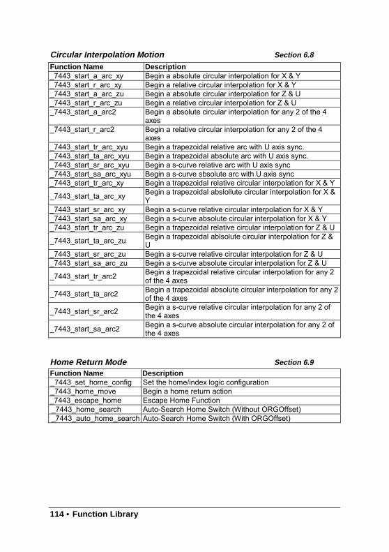
114 • Function Library
Circular Interpolation Motion Section 6.8
Home Return Mode Section 6.9
Function Name Description_7443_start_a_arc_xy Begin a absolute circular interpolation for X & Y_7443_start_r_arc_xy Begin a relative circular interpolation for X & Y_7443_start_a_arc_zu Begin a absolute circular interpolation for Z & U_7443_start_r_arc_zu Begin a relative circular interpolation for Z & U_7443_start_a_arc2 Begin a absolute circular interpolation for any 2 of the 4
axes_7443_start_r_arc2 Begin a relative circular interpolation for any 2 of the 4
axes_7443_start_tr_arc_xyu Begin a trapezoidal relative arc with U axis sync._7443_start_ta_arc_xyu Begin a trapezoidal absolute arc with U axis sync._7443_start_sr_arc_xyu Begin a s-curve relative arc with U axis sync_7443_start_sa_arc_xyu Begin a s-curve sbsolute arc with U axis sync_7443_start_tr_arc_xy Begin a trapezoidal relative circular interpolation for X & Y
_7443_start_ta_arc_xy Begin a trapezoidal abslollute circular interpolation for X &Y
_7443_start_sr_arc_xy Begin a s-curve relative circular interpolation for X & Y_7443_start_sa_arc_xy Begin a s-curve absolute circular interpolation for X & Y_7443_start_tr_arc_zu Begin a trapezoidal relative circular interpolation for Z & U
_7443_start_ta_arc_zu Begin a trapezoidal ablsolute circular interpolation for Z &U
_7443_start_sr_arc_zu Begin a s-curve relative circular interpolation for Z & U_7443_start_sa_arc_zu Begin a s-curve absolute circular interpolation for Z & U
_7443_start_tr_arc2 Begin a trapezoidal relative circular interpolation for any 2of the 4 axes
_7443_start_ta_arc2 Begin a trapezoidal absolute circular interpolation for any 2of the 4 axes
_7443_start_sr_arc2 Begin a s-curve relative circular interpolation for any 2 ofthe 4 axes
_7443_start_sa_arc2 Begin a s-curve absolute circular interpolation for any 2 ofthe 4 axes
Function Name Description_7443_set_home_config Set the home/index logic configuration_7443_home_move Begin a home return action_7443_escape_home Escape Home Function_7443_home_search Auto-Search Home Switch (Without ORGOffset)_7443_auto_home_search Auto-Search Home Switch (With ORGOffset)
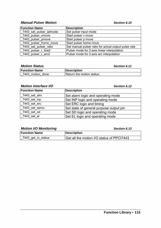
Function Library • 115
Manual Pulser Motion Section 6.10
Motion Status Section 6.11
Motion Interface I/O Section 6.12
Motion I/O Monitoring Section 6.13
Function Name Description_7443_set_pulser_iptmode Set pulser input mode_7443_pulser_vmove Start pulser v move_7443_pulser_pmove Start pulser p move_7443_pulser_home_move Start pulser home move_7443_set_pulser_ratio Set manual pulser ratio for actual output pulse rate_7443_pulser_r_line2 Pulser mode for 2-axis linear interpolation_7443_pulser_r_arc2 Pulser mode for 2-axis arc interpolation
Function Name Description_7443_motion_done Return the motion status
Function Name Description
_7443_set_alm Set alarm logic and operating mode_7443_set_inp Set INP logic and operating mode_7443_set_erc Set ERC logic and timing_7443_set_servo Set state of general purpose output pin_7443_set_sd Set SD logic and operating mode_7443_set_el Set EL logic and operating mode
Function Name Description
_7443_get_io_status Get all the motion I/O status of PPCI7443
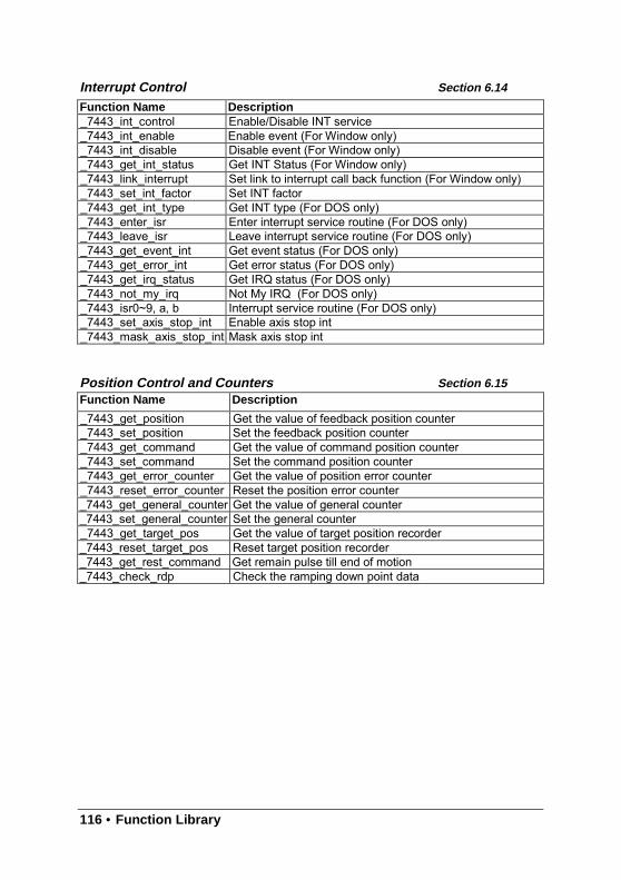
116 • Function Library
Interrupt Control Section 6.14
Position Control and Counters Section 6.15
Function Name Description_7443_int_control Enable/Disable INT service_7443_int_enable Enable event (For Window only)_7443_int_disable Disable event (For Window only)_7443_get_int_status Get INT Status (For Window only)_7443_link_interrupt Set link to interrupt call back function (For Window only)_7443_set_int_factor Set INT factor_7443_get_int_type Get INT type (For DOS only)_7443_enter_isr Enter interrupt service routine (For DOS only)_7443_leave_isr Leave interrupt service routine (For DOS only)_7443_get_event_int Get event status (For DOS only)_7443_get_error_int Get error status (For DOS only)_7443_get_irq_status Get IRQ status (For DOS only)_7443_not_my_irq Not My IRQ (For DOS only)_7443_isr0~9, a, b Interrupt service routine (For DOS only)_7443_set_axis_stop_int Enable axis stop int_7443_mask_axis_stop_int Mask axis stop int
Function Name Description
_7443_get_position Get the value of feedback position counter_7443_set_position Set the feedback position counter_7443_get_command Get the value of command position counter_7443_set_command Set the command position counter_7443_get_error_counter Get the value of position error counter_7443_reset_error_counter Reset the position error counter_7443_get_general_counter Get the value of general counter_7443_set_general_counter Set the general counter_7443_get_target_pos Get the value of target position recorder_7443_reset_target_pos Reset target position recorder_7443_get_rest_command Get remain pulse till end of motion_7443_check_rdp Check the ramping down point data
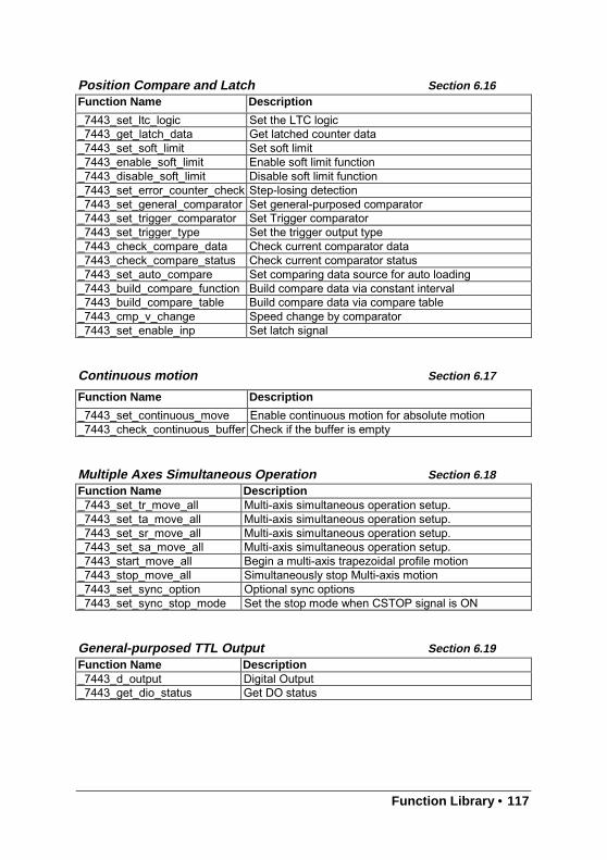
Function Library • 117
Position Compare and Latch Section 6.16
Continuous motion Section 6.17
Multiple Axes Simultaneous Operation Section 6.18
General-purposed TTL Output Section 6.19
Function Name Description
_7443_set_ltc_logic Set the LTC logic_7443_get_latch_data Get latched counter data_7443_set_soft_limit Set soft limit_7443_enable_soft_limit Enable soft limit function_7443_disable_soft_limit Disable soft limit function_7443_set_error_counter_check Step-losing detection_7443_set_general_comparator Set general-purposed comparator_7443_set_trigger_comparator Set Trigger comparator_7443_set_trigger_type Set the trigger output type_7443_check_compare_data Check current comparator data_7443_check_compare_status Check current comparator status_7443_set_auto_compare Set comparing data source for auto loading_7443_build_compare_function Build compare data via constant interval_7443_build_compare_table Build compare data via compare table_7443_cmp_v_change Speed change by comparator_7443_set_enable_inp Set latch signal
Function Name Description
_7443_set_continuous_move Enable continuous motion for absolute motion_7443_check_continuous_buffer Check if the buffer is empty
Function Name Description_7443_set_tr_move_all Multi-axis simultaneous operation setup._7443_set_ta_move_all Multi-axis simultaneous operation setup._7443_set_sr_move_all Multi-axis simultaneous operation setup._7443_set_sa_move_all Multi-axis simultaneous operation setup._7443_start_move_all Begin a multi-axis trapezoidal profile motion_7443_stop_move_all Simultaneously stop Multi-axis motion_7443_set_sync_option Optional sync options_7443_set_sync_stop_mode Set the stop mode when CSTOP signal is ON
Function Name Description_7443_d_output Digital Output_7443_get_dio_status Get DO status
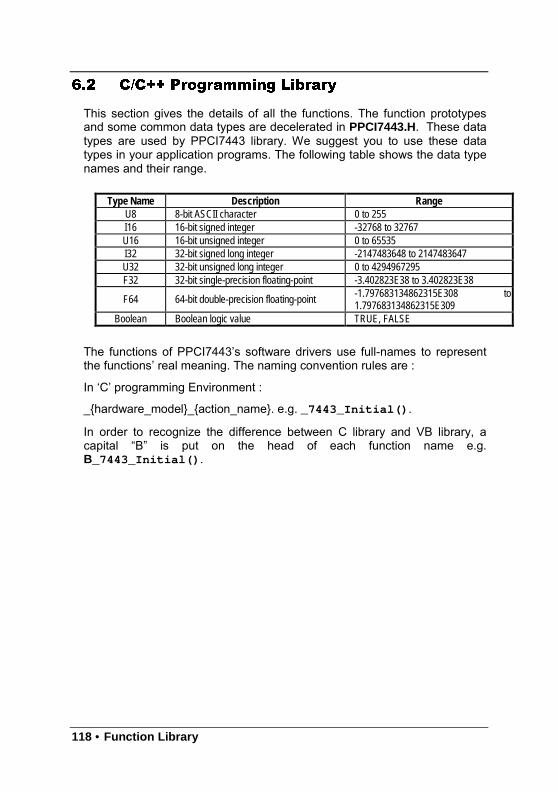
118 • Function Library
6.2 C/C++ Programming Library
This section gives the details of all the functions. The function prototypesand some common data types are decelerated in PPCI7443.H. These datatypes are used by PPCI7443 library. We suggest you to use these datatypes in your application programs. The following table shows the data typenames and their range.
Type Name Description Range U8 8-bit ASCII character 0 to 255 I16 16-bit signed integer -32768 to 32767 U16 16-bit unsigned integer 0 to 65535 I32 32-bit signed long integer -2147483648 to 2147483647 U32 32-bit unsigned long integer 0 to 4294967295 F32 32-bit single-precision floating-point -3.402823E38 to 3.402823E38
F64 64-bit double-precision floating-point -1.797683134862315E308 to 1.797683134862315E309
Boolean Boolean logic value TRUE, FALSE
The functions of PPCI7443’s software drivers use full-names to representthe functions’ real meaning. The naming convention rules are :
In ‘C’ programming Environment :
_hardware_model_action_name. e.g. _7443_Initial().
In order to recognize the difference between C library and VB library, acapital “B” is put on the head of each function name e.g.B_7443_Initial().
Function Library • 119
6.3 Initialization
@ Name_7443_Initial – Software Initialization for PPCI7443_7443_close – Software release resources of PPCI7443_7443_get_base_addr – Get the base address of PPCI7443_7443_get_irq_channel – Get the PPCI7443 card’s IRQ number_7443_delay_time – delay execution of program for specified time in unit of ms._7443_config_from_file – Configure PPCI7443 card according to configuration
file ie. 7443.ini._7443_version_info – Check hardware and software version information
@ Description_7443_Initial :
This function is used to initialize PPCI7443 card. All PPCI7443 cardsmust be initialized by this function before calling other functions.
_7443_close :This function is used to close PPCI7443 card and release thePPCI7443 related resources, which should be called at the end of anapplication.
_7443_get_irq_channel :This function is used to get the PPCI7443 card’s IRQ number.
_7443_get_base_addr:This function is used to get the PPCI7443 card’s base address.
_7443_delay_time:This function is used to delay execution of program for specified timein unit of ms.
_7443_config_from_file:This function is used to load the configuration of PPCI7443 accordingto specified file. By using PPCI7443 Utility , user can test andconfigure PPCI7443 correctly. After pressing “save config” button,the 7443.ini file in window directory is used to record theconfigurations. By specifying it in the parameter, the configuration willbe automatically loaded.When this function is executed, all PPCI7443 cards in the system willbe configured as the following functions were called according toparameters recorded in 7443.ini.
_7443_set_pls_outmode_7443_set_feedback_src_7443_set_pls_iptmode_7443_set_home_config_7443_set_int_factor_7443_set_el_7443_set_ltc_logic_7443_set_erc_7443_set_sd_7443_set_alm_7443_set_inp
120 • Function Library
_7443_set_move_ratio
_7443_version_info:Let users readback version infomation.
@ Syntax
C/C++ (DOS, Windows 95/NT)I16 _7443_initial(I16 *existCards);I16 _7443_close(void);I16 _7443_get_irq_channel(I16 cardNo, U16 *irq_no );I16 _7443_get_base_addr(I16 cardNo, U16 *base_addr );I16 _7443_delay_time(I16 AxisNo,Double MiniSec);I16 _7443_config_from_file(char *filename);I16 _7443_version_info(I16 CardNo, U16 *HardwareInfo, U16*SoftwareInfo, U16 *DriverInfo);
Visual Basic (Windows 95/NT)B_7443_initial (existCards As Integer) As IntegerB_7443_close () As IntegerB_7443_get_irq_channel (ByVal CardNo As Integer, irq_no As Integer) As
IntegerB_7443_get_base_addr (ByVal CardNo As Integer, base_addr As Integer)
As IntegerB_7443_delay_time (ByVal AxisNo As Integer, ByVal MiniSec As Double)
As IntegerB_7443_config_from_file(ByVal filename As string)as integerB_7443_version_info (ByVal CardNo As Integer, HardwareInfo As Integer,
SoftwareInfo As Integer, DriverInfo As Integer) As Integer
@ Argument*existCards: numbers of existing PPCI7443 cardscardNo : The PPCI7443 card index number.*irq_no : Irq number of specified PPCI7443 card.*base_addr : base address of specified PPCI7443 card*Filename : The specified filename recording the configuration of PPCI7443.
This file must be created by PPCI7443 Utility.AxisNo : axis number designated to move or stop.MiniSec : Delay time(unit of ms)*Hardwareinfo : Hardware version readback*SoftwareInfo : Software library version readback*DriverInfo : Device driver version readback
@ Return Code
ERR_NoErroeERR_NoCardFoundERR_PCIBiosNotExistERR_ConigFileOpenError
Function Library • 121
6.4 Pulse Input/Output Configuration
@ Name_7443_set_pls_outmode – Set the configuration for pulse command output._7443_set_pls_iptmode – Set the configuration for feedback pulse input._7443_set_feedback_src – Enable/Disable the external feedback pulse input
@ Description_7443_set_pls_outmode:
Configure the output modes of command pulse. There are 6 modesfor command pulse output.
_7443_set_pls_iptmode:Configure the input modes of external feedback pulse. There are fourtypes for feedback pulse input. Note that this function makes senseonly when Src parameter in _7443_set_feedback_src () function isenabled.
_7443_set_feedback_src:If external encoder feedback is available in the system, set the Srcparameter in this function to Enabled state. Then internal 28-bitup/down counter will count according configuration of_7443_set_pls_iptmode() function. Or the counter will count thecommand pulse output.
@ Syntax
C/C++ (DOS, Windows 95/NT)I16 _7443_set_pls_outmode(I16 AxisNo, I16 pls_outmode);I16 _7443_set_pls_iptmode(I16 AxisNo, I16 pls_iptmode, I16 pls_logic);I16 _7443_set_feedback_src(I16 AxisNo, I16 Src);
Visual Basic (Windows 95/NT)B_7443_set_pls_outmode (ByVal AxisNo As Integer, ByVal pls_outmode
As Integer) As IntegerB_7443_set_pls_iptmode (ByVal AxisNo As Integer, ByVal pls_iptmode As
Integer, ByVal pls_logic As Integer) As IntegerB_7443_set_feedback_src (ByVal AxisNo As Integer, ByVal Src As Integer)
As Integer
122 • Function Library
@ ArgumentAxisNo : axis number designated to configure pulse Input/Output.pls_outmode: setting of command pulse output mode
ValueMeaning0 OUT/DIR OUT Falling edge, DIR+ is high level1 OUT/DIR OUT Rising edge, DIR+ is high level2 OUT/DIR OUT Falling edge, DIR+ is low level3 OUT/DIR OUT Rising edge, DIR+ is low level4 CW/CCW Falling edge5 CW/CCW Rising edge
pls_iptmode: setting of encoder feedback pulse input modeValueMeaning0 1X A/B1 2X A/B2 4X A/B3 CW/CCW
pls_logic : Logic of encoder feedback pulsepls_logic=0, Normal low.pls_logic=1, Normal high
Src : Counter sourceValueMeaning0 External Feedback1 Command pulse
@ Return Code
ERR_NoError
Function Library • 123
6.5 Velocity mode motion
@ Name_7443_tv_move – Accelerate an axis to a constant velocity with trapezoidal
profile_7443_sv_move – Accelerate an axis to a constant velocity with S-curve profile_7443_v_change –Change speed on the fly_7443_sd_stop –Decelerate to stop_7443_emg_stop –Immediately stop_7443_fix_speed_range – Define the speed range_7443_unfix_speed_range – Release the speed range constrain_7443_get_current_speed – Get current speed_7443_verify_speed – get speed profile’s minimum and maximum acc/dec time
@ Description_7443_tv_move:
This function is to accelerate an axis to the specified constantvelocity with trapezoidal profile. The axis will continue to travel at aconstant velocity until the velocity is changed or the axis iscommanded to stop. The direction is determined by the sign ofvelocity parameter.
_7443_sv_move:This function is to accelerate an axis to the specified constantvelocity with S-curve profile. The axis will continue to travel at aconstant velocity until the velocity is changed or the axis iscommanded to stop. The direction is determined by the sign ofvelocity parameter.
_7443_v_change:This function changes the moving velocity with trapezoidal profile orS-curve profile. Before calling this function, it is necessary to definethe speed range by _7443_fix_speed_range. _7443_v_change isalso applicable on pre-set motion. Note: The velocity profile isdecided by original motion profile. When using in S-curve, please setthe motion to be pure S-curve. There are some limitations for thisfunction, please refer to section 4.6.1 before use it.
_7443_sd_stop:This function is used to decelerate an axis to stop with trapezoidalprofile or S-curve profile. This function is also useful when presetmove (both trapezoidal and S-curve motion), manual move orhome return function is performed. Note: The velocity profile isdecided by original motion profile.
_7443_emg_stop:This function is used to immediately stop an axis. This function isalso useful when preset move (both trapezoidal and S-curve motion),manual move or home return function is performed.
_7443_fix_speed_rangeThis function is used to define the speed range. It should be called
124 • Function Library
before starting motion that may contains velocity changing._7443_unfix_speed_range
This function is used to Release the speed range constrain._7443_get_current_speed
This function is used to read current pulse output rate of specifiedaxis. It is applicable in any time and any operating mode.
_7443_verify_speedFind a speed profile’s minimum and maximum acc/time time.
@ Syntax
C/C++ (DOS, Windows 95/NT)I16 _7443_tv_move(I16 AxisNo, F64 StrVel, F64 MaxVel, F64 Tacc);I16 _7443_sv_move(I16 AxisNo, F64 StrVel, F64 MaxVel, F64 Tacc, F64
SVacc);I16 _7443_v_change(I16 AxisNo, F64 NewVel, F64 Tacc);I16 _7443_sd_stop(I16 AxisNo,F64 Tdec);I16 _7443_emg_stop(I16 AxisNo);F64 _7443_fix_speed_range(I16 AxisNo, F64 MaxVel);I16 _7443_unfix_speed_range(I16 AxisNo);I16 _7443_get_current_speed(I16 AxisNo, F64 *speed);F64 _7443_verify_speed(F64 StrVel,F64 MaxVel,F64 *minAccT,F64
*maxAccT, F64 MaxSpeed);
Visual Basic (Windows 95/NT)B_7443_tv_move (ByVal AxisNo As Integer, ByVal StrVel As Double, ByVal
MaxVel As Double, ByVal Tacc As Double) As IntegerB_7443_sv_move (ByVal AxisNo As Integer, ByVal StrVel As Double,
ByVal MaxVel As Double, ByVal Tacc As Double, ByVal SVacc AsDouble) As Integer
B_7443_v_change (ByVal AxisNo As Integer, ByVal NewVel As Double,ByVal TimeSecond As Double) As Integer
B_7443_sd_stop (ByVal AxisNo As Integer, ByVal Tdec As Double) AsInteger
B_7443_emg_stop (ByVal AxisNo As Integer) As IntegerB_7443_fix_speed_range (ByVal AxisNo As Integer, ByVal MaxVel As
Double) As IntegerB_7443_unfix_speed_range (ByVal AxisNo As Integer) As IntegerB_7443_get_current_speed (ByVal AxisNo As Integer, Speed As Double)
As IntegerB_7443_verify_speed (ByVal StrVel As Double, ByVal MaxVel As Double,
minAccT As Double, maxAccT As Double, ByVal MaxSpeed AsDouble) As Double
Function Library • 125
@ ArgumentAxisNo : axis number designated to move or stop.StrVel : starting velocity in unit of pulse per secondMaxVel : maximum velocity in unit of pulse per secondTacc: specified acceleration time in unit of secondSVacc: specified velocity interval in which S-curve acceleration is
performed.Note: SVacc = 0, for pure S-curve
NewVel : New velocity in unit of pulse per secondTdec : specified deceleration time in unit of second*Speed: Variable to save current speed.
(speed range: 0~6553500)minAccT : Minimum acceleration time .maxAcct: Maximum acceleration timeMaxSpeed : The speed set by Fix_Speed
@ Return Code
ERR_NoErrorERR_SpeedErrorERR_SpeedChangeErrorERR_SlowDownPointErrorERR_AxisAlreadyStop
126 • Function Library
6.6 Single Axis Position Mode
@ Name_7443_start_tr_move – Begin a relative trapezoidal profile move_7443_start_ta_move – Begin an absolute trapezoidal profile move_7443_start_sr_move – Begin a relative S-curve profile move_7443_start_sa_move – Begin an absolute S-curve profile move_7443_set_move_ratio –Set the ratio of command pulse and feedback pulse._7443_p_change – Change position on the fly_7443_set_pcs_logic –Set the logic of PCS (Position Change Signal) pin_7443_set_sd_pin –Set SD/PCS pin_7443_backlash_comp – Set backlash compensating pulse for compensation_7443_suppress_vibration – Set vibration suppressing timing_7443_set_idle_pulse – Set suppress vibration idle pulse counts
@ Description
General: The moving direction is determined by the sign of Pos or Distparameter. If the moving distance is too short to reach the specifiedvelocity, the controller will automatically lower the MaxVel ,and theTacc, Tdec, SVacc, SVdec, will also become shorter while thedV/dt(acceleration / deceleration) and d(dV/dt)/dt (jerk) keepunchanged.
_7443_start_tr_move:This function causes the axis to accelerate from a starting velocity,slew at constant velocity, and decelerate to stop at the relativedistance with trapezoidal profile. The acceleration and decelerationtime is specified independently. It won’t let the program wait formotion completion but immediately return control to the program.
_7443_start_ta_move :This function causes the axis to accelerate from a starting velocity,slew at constant velocity, and decelerate to stop at the specifiedabsolute position with trapezoidal profile. The acceleration anddeceleration time is specified independently. It won’t let the programwait for motion completion but immediately return control to theprogram.
_7443_start_sr_move:This function causes the axis to accelerate from a starting velocity,slew at constant velocity, and decelerate to stop at the relativedistance with S-curve profile. The acceleration and deceleration timeis specified independently. It won’t let the program wait for motioncompletion but immediately return control to the program.
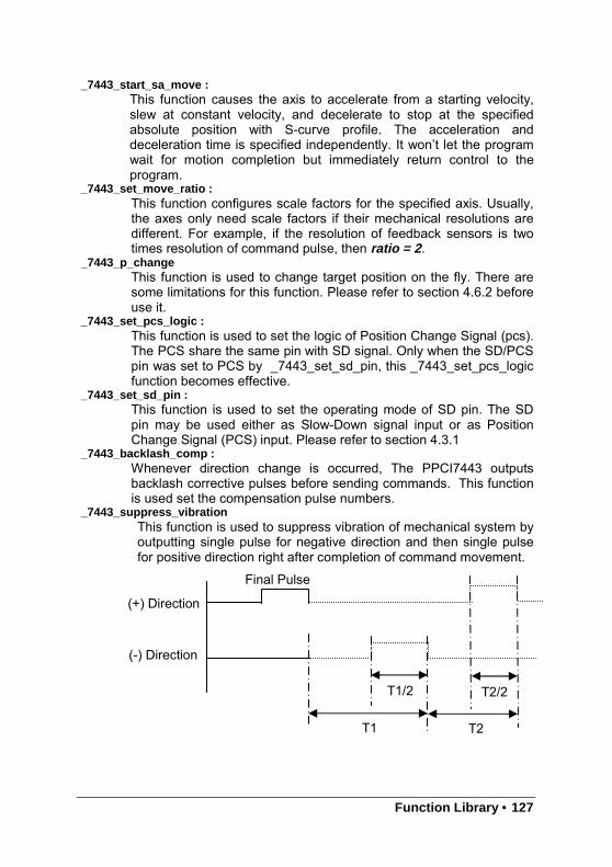
Function Library • 127
_7443_start_sa_move :This function causes the axis to accelerate from a starting velocity,slew at constant velocity, and decelerate to stop at the specifiedabsolute position with S-curve profile. The acceleration anddeceleration time is specified independently. It won’t let the programwait for motion completion but immediately return control to theprogram.
_7443_set_move_ratio :This function configures scale factors for the specified axis. Usually,the axes only need scale factors if their mechanical resolutions aredifferent. For example, if the resolution of feedback sensors is twotimes resolution of command pulse, then ratio = 2 .
_7443_p_changeThis function is used to change target position on the fly. There aresome limitations for this function. Please refer to section 4.6.2 beforeuse it.
_7443_set_pcs_logic :This function is used to set the logic of Position Change Signal (pcs).The PCS share the same pin with SD signal. Only when the SD/PCSpin was set to PCS by _7443_set_sd_pin, this _7443_set_pcs_logicfunction becomes effective.
_7443_set_sd_pin :This function is used to set the operating mode of SD pin. The SDpin may be used either as Slow-Down signal input or as PositionChange Signal (PCS) input. Please refer to section 4.3.1
_7443_backlash_comp :Whenever direction change is occurred, The PPCI7443 outputsbacklash corrective pulses before sending commands. This functionis used set the compensation pulse numbers.
_7443_suppress_vibrationThis function is used to suppress vibration of mechanical system byoutputting single pulse for negative direction and then single pulsefor positive direction right after completion of command movement.
(+) Direction
(-) Direction
Final Pulse
T1 T2
T1/2 T2/2
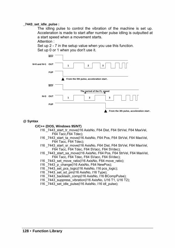
128 • Function Library
_7443_set_idle_pulse :The idling pulse to control the vibration of the machine is set up.Acceleration is made to start after number pulse idling is outputted ata start speed when a movement starts.Attention :Set up 2 - 7 in the setup value when you use this function.Set up 0 or 1 when you don't use it.
@ Syntax
C/C++ (DOS, Windows 95/NT)I16 _7443_start_tr_move(I16 AxisNo, F64 Dist, F64 StrVel, F64 MaxVel,
F64 Tacc,F64 Tdec);I16 _7443_start_ta_move(I16 AxisNo, F64 Pos, F64 StrVel, F64 MaxVel,
F64 Tacc, F64 Tdec);I16 _7443_start_sr_move(I16 AxisNo, F64 Dist, F64 StrVel, F64 MaxVel,
F64 Tacc, F64 Tdec, F64 SVacc, F64 SVdec);I16 _7443_start_sa_move(I16 AxisNo, F64 Pos, F64 StrVel, F64 MaxVel,
F64 Tacc, F64 Tdec, F64 SVacc, F64 SVdec);I16 _7443_set_move_ratio(I16 AxisNo, F64 move_ratio);I16 _7443_p_change(I16 AxisNo, F64 NewPos);I16 _7443_set_pcs_logic(I16 AxisNo, I16 pcs_logic);I16 _7443_set_sd_pin(I16 AxisNo, I16 Type);I16 _7443_backlash_comp(I16 AxisNo, I16 BCompPulse);I16 _7443_suppress_vibration(I16 AxisNo, U16 T1, U16 T2);I16 _7443_set_idle_pulse(I16 AxisNo, I16 idl_pulse);
BSY
OUT1 2 3
FUP
From the 0th pulse, acceleration start .
BSY
OUT1 2 3
FUP
From the 3th pulse, acceleration start .
The period of the FL speed
N=0 and N=1
N=3

Function Library • 129
Visual Basic (Windows 95/NT)B_7443_start_tr_move (ByVal AxisNo As Integer, ByVal Dist As Double,
ByVal StrVel As Double, ByVal MaxVel As Double, ByVal Tacc AsDouble, ByVal Tdec As Double) As Integer
B_7443_start_ta_move (ByVal AxisNo As Integer, ByVal Pos As Double,ByVal StrVel As Double, ByVal MaxVel As Double, ByVal Tacc AsDouble, ByVal Tdec As Double) As Integer
B_7443_start_sr_move (ByVal AxisNo As Integer, ByVal Dist As Double,ByVal StrVel As Double, ByVal MaxVel As Double, ByVal Tacc AsDouble, ByVal Tdec As Double, ByVal SVacc As Double, ByValSVdec As Double) As Integer
B_7443_start_sa_move (ByVal AxisNo As Integer, ByVal Pos As Double,ByVal StrVel As Double, ByVal MaxVel As Double, ByVal Tacc AsDouble, ByVal Tdec As Double, ByVal SVacc As Double, ByValSVdec As Double) As Integer
B_7443_set_move_ratio (ByVal AxisNo As Integer, ByVal move_ratio AsDouble) As Integer
B_7443_p_change (ByVal AxisNo As Integer, ByVal NewPos As Double)As Integer
B_7443_set_pcs_logic (ByVal AxisNo As Integer, ByVal pcs_logic AsInteger) As Integer
B_7443_set_sd_pin (ByVal AxisNo As Integer, ByVal Type As Integer) AsInteger
B_7443_backlash_comp (ByVal AxisNo As Integer, ByVal BCompPulse AsInteger, ByVal ForwardTime As Integer) As Integer
B_7443_suppress_vibration (ByVal AxisNo As Integer, ByVal ReserveTimeAs Integer, ByVal ForwardTime As Integer) As Integer
B_7443_set_idle_pulse(ByVal AxisNo As Integer, ByVal idl_pulse AsInteger);
130 • Function Library
@ ArgumentAxisNo : axis number designated to move or change position.Dist: specified relative distance to movePos : specified absolute position to moveStrVel : starting velocity of a velocity profile in unit of pulse per secondMaxVel : maximum velocity of a velocity profile in unit of pulse per secondTacc: specified acceleration time in unit of secondTdec : specified deceleration time in unit of secondSVacc: specified velocity interval in which S-curve acceleration is
performed.Note: SVacc = 0, for pure S-curve
SVdec : specified velocity interval in which S-curve deceleration isperformed.Note: SVdec = 0, for pure S-curve
Move_ratio : ratio of (feedback resolution)/(command resolution) , shouldnot be 0
NewPos: specified new absolute position to movepcs_logic: Specify he pcs logic.
Value = 0: low active ,Value = 1: high active
Type : define the SD pin usageValue = 0 : SD pin as SD signalValue = 1: SD pin as PCS signal
BcompPulse : Specified number of corrective pulsesT1: Specified Reverse TimeT2: Specified Forward TimeIdl_pulse : Idl_pulse=0~7
@ Return Code
ERR_NoErrorERR_SpeedErrorERR_PChangeSlowDownPointErrorERR_MoveRatioError
Function Library • 131
6.7 Linear Interpolated Motion
@ Name_7443_start_tr_move_xy – Begin a relative 2-axis linear interpolation for X & Y,
with trapezoidal profile,_7443_start_ta_move_xy – Begin a absolute 2-axis linear interpolation for X & Y,
with trapezoidal profile,_7443_start_sr_move_xy – Begin a relative 2-axis linear interpolation for X & Y,
with S-curve profile,_7443_start_sa_move_xy – Begin a absolute 2-axis linear interpolation for X & Y,
with S-curve profile,_7443_start_tr_move_zu – Begin a relative 2-axis linear interpolation for Z & U,
with trapezoidal profile,_7443_start_ta_move_zu – Begin a absolute 2-axis linear interpolation for Z & U,
with trapezoidal profile,_7443_start_sr_move_zu – Begin a relative 2-axis linear interpolation for Z & U,
with S-curve profile,_7443_start_sa_move_zu – Begin a absolute 2-axis linear interpolation for Z & U,
with S-curve profile,_7443_start_tr_line2 – Begin a relative 2-axis linear interpolation for any 2 axes,
with trapezoidal profile,_7443_start_sr_line2 – Begin a relative 2-axis linear interpolation for any 2 axes,,
with S-curve profile_7443_start_ta_line2 – Begin a absolute 2-axis linear interpolation for any 2 axes,,
with trapezoidal profile_7443_start_sa_line2 – Begin a absolute 2-axis linear interpolation for any 2 axes,,
with S-curve profile,_7443_start_tr_line3 – Begin a relative 3-axis linear interpolation with trapezoidal
profile,_7443_start_sr_line3 – Begin a relative 3-axis linear interpolation with S-curve
profile_7443_start_ta_line3 – Begin a absolute 3-axis linear interpolation with
trapezoidal profile_7443_start_sa_line3 – Begin a absolute 3-axis linear interpolation with S-curve
profile,_7443_start_tr_line4 – Begin a relative 4-axis linear interpolation with trapezoidal
profile,_7443_start_sr_line4 – Begin a relative 4-axis linear interpolation with S-curve
profile_7443_start_ta_line4 – Begin a absolute 4-axis linear interpolation with
trapezoidal profile_7443_start_sa_line4 – Begin a absolute 4-axis linear interpolation with S-curve
profile,_7443_set_line_move_mode – Set continuous line interpolation mode_7443_set_axis_option – Choose the interpolation speed mode
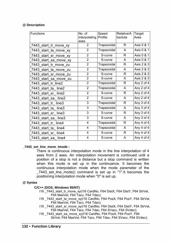
132 • Function Library
@ Description
Functions No. ofinterpolatingaxes
SpeedProfile
Relative/Absolute
TargetAxes
_7443_start_tr_move_xy 2 Trapezoidal R Axis 0 & 1_7443_start_ta_move_xy 2 Trapezoidal A Axis 0 & 1
_7443_start_sr_move_xy 2 S-curve R Axis 0 & 1_7443_start_sa_move_xy 2 S-curve A Axis 0 & 1_7443_start_tr_move_zu 2 Trapezoidal R Axis 2 & 3_7443_start_ta_move_zu 2 Trapezoidal A Axis 2 & 3_7443_start_sr_move_zu 2 S-curve R Axis 2 & 3_7443_start_sa_move_zu 2 S-curve A Axis 2 & 3_7443_start_tr_line2 2 Trapezoidal R Any 2 of 4_7443_start_ta_ line2 2 Trapezoidal A Any 2 of 4
_7443_start_sr_ line2 2 S-curve R Any 2 of 4
_7443_start_sa_ line2 2 S-curve A Any 2 of 4
_7443_start_tr_ line3 3 Trapezoidal R Any 3 of 4
_7443_start_ta_ line3 3 Trapezoidal A Any 3 of 4
_7443_start_sr_ line3 3 S-curve R Any 3 of 4
_7443_start_sa_ line3 3 S-curve A Any 3 of 4
_7443_start_tr_ line4 4 Trapezoidal R Any 4 of 4
_7443_start_ta_ line4 4 Trapezoidal A Any 4 of 4
_7443_start_sr_ line4 4 S-curve R Any 4 of 4
_7443_start_sa_ line4 4 S-curve A Any 4 of 4
_7443_set_line_move_tmode :There is continuous interpolation mode in the line interpolation of 4axes from 2 axes. An interpolation movement is continued until aposition of a stop is not a distance but a stop command is writtenwhen this mode is set up in the continuance. It becomes thecontinuous interpolation mode when the mode parameter of the_7443_set_line_mode() command is set up in "1".It becomes thepositioning interpolation mode when "0" is set up.
@ Syntax
C/C++ (DOS, Windows 95/NT)I16 _7443_start_tr_move_xy(I16 CardNo, F64 DistX, F64 DistY, F64 StrVel,
F64 MaxVel, F64 Tacc, F64 Tdec);I16 _7443_start_ta_move_xy(I16 CardNo, F64 PosX, F64 PosY, F64 StrVel,
F64 MaxVel, F64 Tacc, F64 Tdec);I16 _7443_start_sr_move_xy(I16 CardNo, F64 DistX, F64 DistY, F64 StrVel,
F64 MaxVel, F64 Tacc, F64 Tdec, F64 SVacc, F64 SVdec);I16 _7443_start_sa_move_xy(I16 CardNo, F64 PosX, F64 PosY, F64
StrVel, F64 MaxVel, F64 Tacc, F64 Tdec, F64 SVacc, F64 SVdec);
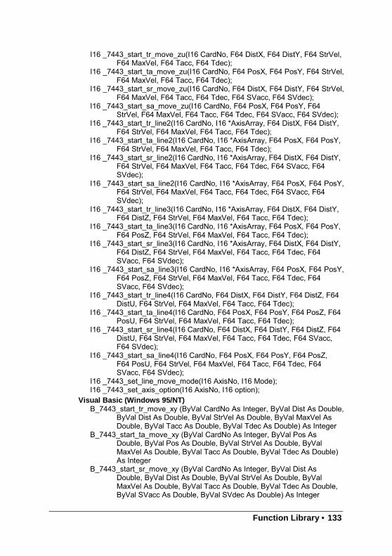
Function Library • 133
I16 _7443_start_tr_move_zu(I16 CardNo, F64 DistX, F64 DistY, F64 StrVel,F64 MaxVel, F64 Tacc, F64 Tdec);
I16 _7443_start_ta_move_zu(I16 CardNo, F64 PosX, F64 PosY, F64 StrVel,F64 MaxVel, F64 Tacc, F64 Tdec);
I16 _7443_start_sr_move_zu(I16 CardNo, F64 DistX, F64 DistY, F64 StrVel,F64 MaxVel, F64 Tacc, F64 Tdec, F64 SVacc, F64 SVdec);
I16 _7443_start_sa_move_zu(I16 CardNo, F64 PosX, F64 PosY, F64StrVel, F64 MaxVel, F64 Tacc, F64 Tdec, F64 SVacc, F64 SVdec);
I16 _7443_start_tr_line2(I16 CardNo, I16 *AxisArray, F64 DistX, F64 DistY,F64 StrVel, F64 MaxVel, F64 Tacc, F64 Tdec);
I16 _7443_start_ta_line2(I16 CardNo, I16 *AxisArray, F64 PosX, F64 PosY,F64 StrVel, F64 MaxVel, F64 Tacc, F64 Tdec);
I16 _7443_start_sr_line2(I16 CardNo, I16 *AxisArray, F64 DistX, F64 DistY,F64 StrVel, F64 MaxVel, F64 Tacc, F64 Tdec, F64 SVacc, F64SVdec);
I16 _7443_start_sa_line2(I16 CardNo, I16 *AxisArray, F64 PosX, F64 PosY,F64 StrVel, F64 MaxVel, F64 Tacc, F64 Tdec, F64 SVacc, F64SVdec);
I16 _7443_start_tr_line3(I16 CardNo, I16 *AxisArray, F64 DistX, F64 DistY,F64 DistZ, F64 StrVel, F64 MaxVel, F64 Tacc, F64 Tdec);
I16 _7443_start_ta_line3(I16 CardNo, I16 *AxisArray, F64 PosX, F64 PosY,F64 PosZ, F64 StrVel, F64 MaxVel, F64 Tacc, F64 Tdec);
I16 _7443_start_sr_line3(I16 CardNo, I16 *AxisArray, F64 DistX, F64 DistY,F64 DistZ, F64 StrVel, F64 MaxVel, F64 Tacc, F64 Tdec, F64SVacc, F64 SVdec);
I16 _7443_start_sa_line3(I16 CardNo, I16 *AxisArray, F64 PosX, F64 PosY,F64 PosZ, F64 StrVel, F64 MaxVel, F64 Tacc, F64 Tdec, F64SVacc, F64 SVdec);
I16 _7443_start_tr_line4(I16 CardNo, F64 DistX, F64 DistY, F64 DistZ, F64DistU, F64 StrVel, F64 MaxVel, F64 Tacc, F64 Tdec);
I16 _7443_start_ta_line4(I16 CardNo, F64 PosX, F64 PosY, F64 PosZ, F64PosU, F64 StrVel, F64 MaxVel, F64 Tacc, F64 Tdec);
I16 _7443_start_sr_line4(I16 CardNo, F64 DistX, F64 DistY, F64 DistZ, F64DistU, F64 StrVel, F64 MaxVel, F64 Tacc, F64 Tdec, F64 SVacc,F64 SVdec);
I16 _7443_start_sa_line4(I16 CardNo, F64 PosX, F64 PosY, F64 PosZ,F64 PosU, F64 StrVel, F64 MaxVel, F64 Tacc, F64 Tdec, F64SVacc, F64 SVdec);
I16 _7443_set_line_move_mode(I16 AxisNo, I16 Mode);I16 _7443_set_axis_option(I16 AxisNo, I16 option);
Visual Basic (Windows 95/NT)B_7443_start_tr_move_xy (ByVal CardNo As Integer, ByVal Dist As Double,
ByVal Dist As Double, ByVal StrVel As Double, ByVal MaxVel AsDouble, ByVal Tacc As Double, ByVal Tdec As Double) As Integer
B_7443_start_ta_move_xy (ByVal CardNo As Integer, ByVal Pos AsDouble, ByVal Pos As Double, ByVal StrVel As Double, ByValMaxVel As Double, ByVal Tacc As Double, ByVal Tdec As Double)As Integer
B_7443_start_sr_move_xy (ByVal CardNo As Integer, ByVal Dist AsDouble, ByVal Dist As Double, ByVal StrVel As Double, ByValMaxVel As Double, ByVal Tacc As Double, ByVal Tdec As Double,ByVal SVacc As Double, ByVal SVdec As Double) As Integer
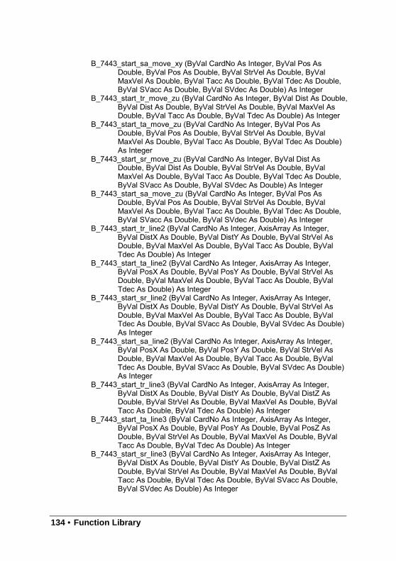
134 • Function Library
B_7443_start_sa_move_xy (ByVal CardNo As Integer, ByVal Pos AsDouble, ByVal Pos As Double, ByVal StrVel As Double, ByValMaxVel As Double, ByVal Tacc As Double, ByVal Tdec As Double,ByVal SVacc As Double, ByVal SVdec As Double) As Integer
B_7443_start_tr_move_zu (ByVal CardNo As Integer, ByVal Dist As Double,ByVal Dist As Double, ByVal StrVel As Double, ByVal MaxVel AsDouble, ByVal Tacc As Double, ByVal Tdec As Double) As Integer
B_7443_start_ta_move_zu (ByVal CardNo As Integer, ByVal Pos AsDouble, ByVal Pos As Double, ByVal StrVel As Double, ByValMaxVel As Double, ByVal Tacc As Double, ByVal Tdec As Double)As Integer
B_7443_start_sr_move_zu (ByVal CardNo As Integer, ByVal Dist AsDouble, ByVal Dist As Double, ByVal StrVel As Double, ByValMaxVel As Double, ByVal Tacc As Double, ByVal Tdec As Double,ByVal SVacc As Double, ByVal SVdec As Double) As Integer
B_7443_start_sa_move_zu (ByVal CardNo As Integer, ByVal Pos AsDouble, ByVal Pos As Double, ByVal StrVel As Double, ByValMaxVel As Double, ByVal Tacc As Double, ByVal Tdec As Double,ByVal SVacc As Double, ByVal SVdec As Double) As Integer
B_7443_start_tr_line2 (ByVal CardNo As Integer, AxisArray As Integer,ByVal DistX As Double, ByVal DistY As Double, ByVal StrVel AsDouble, ByVal MaxVel As Double, ByVal Tacc As Double, ByValTdec As Double) As Integer
B_7443_start_ta_line2 (ByVal CardNo As Integer, AxisArray As Integer,ByVal PosX As Double, ByVal PosY As Double, ByVal StrVel AsDouble, ByVal MaxVel As Double, ByVal Tacc As Double, ByValTdec As Double) As Integer
B_7443_start_sr_line2 (ByVal CardNo As Integer, AxisArray As Integer,ByVal DistX As Double, ByVal DistY As Double, ByVal StrVel AsDouble, ByVal MaxVel As Double, ByVal Tacc As Double, ByValTdec As Double, ByVal SVacc As Double, ByVal SVdec As Double)As Integer
B_7443_start_sa_line2 (ByVal CardNo As Integer, AxisArray As Integer,ByVal PosX As Double, ByVal PosY As Double, ByVal StrVel AsDouble, ByVal MaxVel As Double, ByVal Tacc As Double, ByValTdec As Double, ByVal SVacc As Double, ByVal SVdec As Double)As Integer
B_7443_start_tr_line3 (ByVal CardNo As Integer, AxisArray As Integer,ByVal DistX As Double, ByVal DistY As Double, ByVal DistZ AsDouble, ByVal StrVel As Double, ByVal MaxVel As Double, ByValTacc As Double, ByVal Tdec As Double) As Integer
B_7443_start_ta_line3 (ByVal CardNo As Integer, AxisArray As Integer,ByVal PosX As Double, ByVal PosY As Double, ByVal PosZ AsDouble, ByVal StrVel As Double, ByVal MaxVel As Double, ByValTacc As Double, ByVal Tdec As Double) As Integer
B_7443_start_sr_line3 (ByVal CardNo As Integer, AxisArray As Integer,ByVal DistX As Double, ByVal DistY As Double, ByVal DistZ AsDouble, ByVal StrVel As Double, ByVal MaxVel As Double, ByValTacc As Double, ByVal Tdec As Double, ByVal SVacc As Double,ByVal SVdec As Double) As Integer
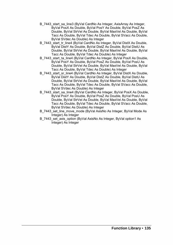
Function Library • 135
B_7443_start_sa_line3 (ByVal CardNo As Integer, AxisArray As Integer,ByVal PosX As Double, ByVal PosY As Double, ByVal PosZ AsDouble, ByVal StrVel As Double, ByVal MaxVel As Double, ByValTacc As Double, ByVal Tdec As Double, ByVal SVacc As Double,ByVal SVdec As Double) As Integer
B_7443_start_tr_line4 (ByVal CardNo As Integer, ByVal DistX As Double,ByVal DistY As Double, ByVal DistZ As Double, ByVal DistU AsDouble, ByVal StrVel As Double, ByVal MaxVel As Double, ByValTacc As Double, ByVal Tdec As Double) As Integer
B_7443_start_ta_line4 (ByVal CardNo As Integer, ByVal PosX As Double,ByVal PosY As Double, ByVal PosZ As Double, ByVal PosU AsDouble, ByVal StrVel As Double, ByVal MaxVel As Double, ByValTacc As Double, ByVal Tdec As Double) As Integer
B_7443_start_sr_line4 (ByVal CardNo As Integer, ByVal DistX As Double,ByVal DistY As Double, ByVal DistZ As Double, ByVal DistU AsDouble, ByVal StrVel As Double, ByVal MaxVel As Double, ByValTacc As Double, ByVal Tdec As Double, ByVal SVacc As Double,ByVal SVdec As Double) As Integer
B_7443_start_sa_line4 (ByVal CardNo As Integer, ByVal PosX As Double,ByVal PosY As Double, ByVal PosZ As Double, ByVal PosU AsDouble, ByVal StrVel As Double, ByVal MaxVel As Double, ByValTacc As Double, ByVal Tdec As Double, ByVal SVacc As Double,ByVal SVdec As Double) As Integer
B_7443_set_line_move_mode (ByVal AxisNo As Integer, ByVal Mode AsInteger) As Integer
B_7443_set_axis_option (ByVal AxisNo As Integer, ByVal option1 AsInteger) As Integer
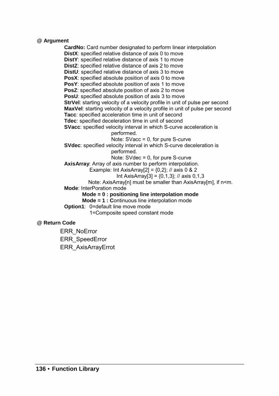
136 • Function Library
@ ArgumentCardNo: Card number designated to perform linear interpolationDistX : specified relative distance of axis 0 to moveDistY : specified relative distance of axis 1 to moveDistZ : specified relative distance of axis 2 to moveDistU: specified relative distance of axis 3 to movePosX : specified absolute position of axis 0 to movePosY : specified absolute position of axis 1 to movePosZ : specified absolute position of axis 2 to movePosU : specified absolute position of axis 3 to moveStrVel : starting velocity of a velocity profile in unit of pulse per secondMaxVel : starting velocity of a velocity profile in unit of pulse per secondTacc: specified acceleration time in unit of secondTdec : specified deceleration time in unit of secondSVacc: specified velocity interval in which S-curve acceleration is
performed.Note: SVacc = 0, for pure S-curve
SVdec : specified velocity interval in which S-curve deceleration isperformed.Note: SVdec = 0, for pure S-curve
AxisArray : Array of axis number to perform interpolation.Example: Int AxisArray[2] = 0,2; // axis 0 & 2
Int AxisArray[3] = 0,1,3; // axis 0,1,3Note: AxisArray[n] must be smaller than AxisArray[m], if n<m.
Mode : InterPoration modeMode = 0 : positioning line interpolation modeMode = 1 : Continuous line interpolation mode
Option1 : 0=default line move mode1=Composite speed constant mode
@ Return Code
ERR_NoErrorERR_SpeedErrorERR_AxisArrayErrot
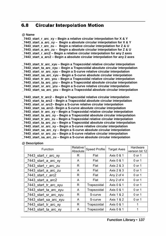
Function Library • 137
6.8 Circular Interpolation Motion
@ Name_7443_start_r_arc_xy – Begin a relative circular interpolation for X & Y_7443_start_a_arc_xy – Begin a absolute circular interpolation for X & Y_7443_start_r_arc_zu – Begin a relative circular interpolation for Z & U_7443_start_a_arc_zu – Begin a absolute circular interpolation for Z & U_7443_start_r_arc2 – Begin a relative circular interpolation for any 2 axes_7443_start_a_arc2 – Begin a absolute circular interpolation for any 2 axes
_7443_start_tr_arc_xyu – Begin a Trapezoidal relative circular interpolation_7443_start_ta_arc_xyu – Begin a Trapezoidal absolute circular interpolation_7443_start_sr_arc_xyu – Begin a S-curve relative circular interpolation_7443_start_sa_arc_xyu – Begin a S-curve absolute circular interpolation_7443_start_tr_arc_yzu – Begin a Trapezoidal relative circular interpolation_7443_start_ta_arc_yzu – Begin a Trapezoidal absolute circular interpolation_7443_start_sr_arc_yzu – Begin a S-curve relative circular interpolation_7443_start_sa_arc_yzu – Begin a Trapezoidal absolute circular interpolation
_7443_start_tr_arc2 – Begin a Trapezoidal relative circular interpolation_7443_start_ta_arc2 – Begin a Trapezoidal absolute circular interpolation_7443_start_sr_arc2– Begin a S-curve relative circular interpolation_7443_start_sa_arc2– Begin a S-curve absolute circular interpolation_7443_start_tr_arc_xy – Begin a Trapezoidal relative circular interpolation_7443_start_ta_arc_xy – Begin a Trapezoidal absolute circular interpolation_7443_start_tr_arc_zu – Begin a Trapezoidal relative circular interpolation_7443_start_ta_arc_zu – Begin a Trapezoidal absolute circular interpolation_7443_start_sr_arc_xy – Begin a S-curve relative circular interpolation_7443_start_sa_arc_xy – Begin a S-curve absolute circular interpolation_7443_start_sr_arc_zu – Begin a S-curve relative circular interpolation_7443_start_sa_arc_zu – Begin a S-curve absolute circular interpolation
@ Description
Function Relative/Absolute Speed Profile Target Axes Hardware
version bit 12_7443_start_r_arc_xy R Flat Axis 0 & 1 0 or 1_7443_start_a_arc_xy A Flat Axis 0 & 1 0 or 1
_7443_start_r_arc_zu R Flat Axis 2 & 3 0 or 1_7443_start_a_arc_zu A Flat Axis 2 & 3 0 or 1_7443_start_r_arc2 R Flat Any 2 of 4 0 or 1_7443_start_a_arc2 A Flat Any 2 of 4 0 or 1
_7443_start_tr_arc_xyu R Trapezoidal Axis 0 & 1 0 or 1_7443_start_ta_arc_xyu A Trapezoidal Axis 0 & 1 0 or 1_7443_start_sr_arc_xyu R S-curve Axis 1 & 2 0 or 1_7443_start_sa_arc_xyu A S-curve Axis 1 & 2 0 or 1
_7443_start_tr_arc_xy R Trapezoidal Axis 0 & 1 1_7443_start_ta_arc_xy A Trapezoidal Axis 0 & 1 1
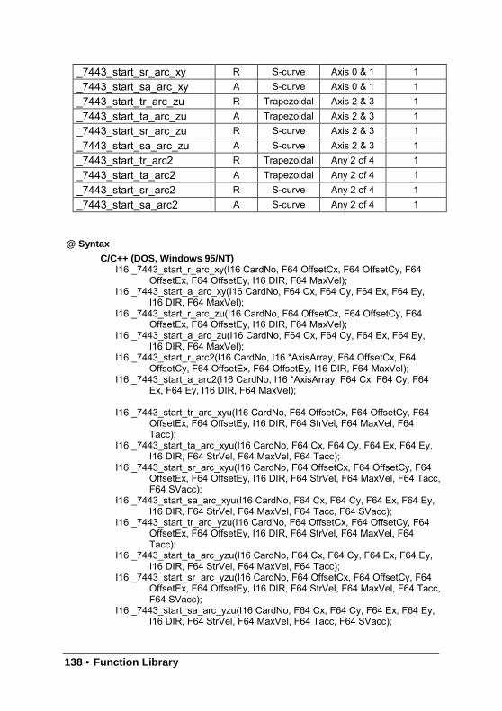
138 • Function Library
_7443_start_sr_arc_xy R S-curve Axis 0 & 1 1_7443_start_sa_arc_xy A S-curve Axis 0 & 1 1_7443_start_tr_arc_zu R Trapezoidal Axis 2 & 3 1_7443_start_ta_arc_zu A Trapezoidal Axis 2 & 3 1_7443_start_sr_arc_zu R S-curve Axis 2 & 3 1_7443_start_sa_arc_zu A S-curve Axis 2 & 3 1_7443_start_tr_arc2 R Trapezoidal Any 2 of 4 1_7443_start_ta_arc2 A Trapezoidal Any 2 of 4 1
_7443_start_sr_arc2 R S-curve Any 2 of 4 1_7443_start_sa_arc2 A S-curve Any 2 of 4 1
@ Syntax
C/C++ (DOS, Windows 95/NT)I16 _7443_start_r_arc_xy(I16 CardNo, F64 OffsetCx, F64 OffsetCy, F64
OffsetEx, F64 OffsetEy, I16 DIR, F64 MaxVel);I16 _7443_start_a_arc_xy(I16 CardNo, F64 Cx, F64 Cy, F64 Ex, F64 Ey,
I16 DIR, F64 MaxVel);I16 _7443_start_r_arc_zu(I16 CardNo, F64 OffsetCx, F64 OffsetCy, F64
OffsetEx, F64 OffsetEy, I16 DIR, F64 MaxVel);I16 _7443_start_a_arc_zu(I16 CardNo, F64 Cx, F64 Cy, F64 Ex, F64 Ey,
I16 DIR, F64 MaxVel);I16 _7443_start_r_arc2(I16 CardNo, I16 *AxisArray, F64 OffsetCx, F64
OffsetCy, F64 OffsetEx, F64 OffsetEy, I16 DIR, F64 MaxVel);I16 _7443_start_a_arc2(I16 CardNo, I16 *AxisArray, F64 Cx, F64 Cy, F64
Ex, F64 Ey, I16 DIR, F64 MaxVel);
I16 _7443_start_tr_arc_xyu(I16 CardNo, F64 OffsetCx, F64 OffsetCy, F64OffsetEx, F64 OffsetEy, I16 DIR, F64 StrVel, F64 MaxVel, F64Tacc);
I16 _7443_start_ta_arc_xyu(I16 CardNo, F64 Cx, F64 Cy, F64 Ex, F64 Ey,I16 DIR, F64 StrVel, F64 MaxVel, F64 Tacc);
I16 _7443_start_sr_arc_xyu(I16 CardNo, F64 OffsetCx, F64 OffsetCy, F64OffsetEx, F64 OffsetEy, I16 DIR, F64 StrVel, F64 MaxVel, F64 Tacc,F64 SVacc);
I16 _7443_start_sa_arc_xyu(I16 CardNo, F64 Cx, F64 Cy, F64 Ex, F64 Ey,I16 DIR, F64 StrVel, F64 MaxVel, F64 Tacc, F64 SVacc);
I16 _7443_start_tr_arc_yzu(I16 CardNo, F64 OffsetCx, F64 OffsetCy, F64OffsetEx, F64 OffsetEy, I16 DIR, F64 StrVel, F64 MaxVel, F64Tacc);
I16 _7443_start_ta_arc_yzu(I16 CardNo, F64 Cx, F64 Cy, F64 Ex, F64 Ey,I16 DIR, F64 StrVel, F64 MaxVel, F64 Tacc);
I16 _7443_start_sr_arc_yzu(I16 CardNo, F64 OffsetCx, F64 OffsetCy, F64OffsetEx, F64 OffsetEy, I16 DIR, F64 StrVel, F64 MaxVel, F64 Tacc,F64 SVacc);
I16 _7443_start_sa_arc_yzu(I16 CardNo, F64 Cx, F64 Cy, F64 Ex, F64 Ey,I16 DIR, F64 StrVel, F64 MaxVel, F64 Tacc, F64 SVacc);
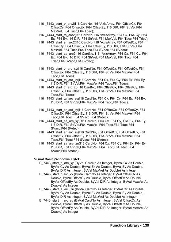
Function Library • 139
I16 _7443_start_tr_arc2(I16 CardNo, I16 *AxisArray, F64 OffsetCx, F64OffsetCy, F64 OffsetEx, F64 OffsetEy, I16 DIR, F64 StrVel,F64MaxVel, F64 Tacc,F64 Tdec);
I16 _7443_start_ta_arc2(I16 CardNo, I16 *AxisArray, F64 Cx, F64 Cy, F64Ex, F64 Ey, I16 DIR, F64 StrVel, F64 MaxVel, F64 Tacc,F64 Tdec);
I16 _7443_start_sr_arc2(I16 CardNo, I16 *AxisArray, F64 OffsetCx, F64OffsetCy, F64 OffsetEx, F64 OffsetEy, I16 DIR, F64 StrVel,F64MaxVel, F64 Tacc,F64 Tdec,F64 SVacc,F64 SVdec);
I16 _7443_start_sa_arc2(I16 CardNo, I16 *AxisArray, F64 Cx, F64 Cy, F64Ex, F64 Ey, I16 DIR, F64 StrVel, F64 MaxVel, F64 Tacc,F64Tdec,F64 SVacc,F64 SVdec);
I16 _7443_start_tr_arc_xy(I16 CardNo, F64 OffsetCx, F64 OffsetCy, F64OffsetEx, F64 OffsetEy, I16 DIR, F64 StrVel,F64 MaxVel,F64Tacc,F64 Tdec);
I16 _7443_start_ta_arc_xy(I16 CardNo, F64 Cx, F64 Cy, F64 Ex, F64 Ey,I16 DIR, F64 StrVel,F64 MaxVel,F64 Tacc,F64 Tdec);
I16 _7443_start_tr_arc_zu(I16 CardNo, F64 OffsetCx, F64 OffsetCy, F64OffsetEx, F64 OffsetEy, I16 DIR, F64 StrVel,F64 MaxVel,F64Tacc,F64 Tdec);
I16 _7443_start_ta_arc_zu(I16 CardNo, F64 Cx, F64 Cy, F64 Ex, F64 Ey,I16 DIR, F64 StrVel,F64 MaxVel,F64 Tacc,F64 Tdec);
I16 _7443_start_sr_arc_xy(I16 CardNo, F64 OffsetCx, F64 OffsetCy, F64OffsetEx, F64 OffsetEy, I16 DIR, F64 StrVel,F64 MaxVel, F64Tacc,F64 Tdec,F64 SVacc,F64 SVdec);
I16 _7443_start_sa_arc_xy(I16 CardNo, F64 Cx, F64 Cy, F64 Ex, F64 Ey,I16 DIR, F64 StrVel,F64 MaxVel, F64 Tacc,F64 Tdec,F64SVacc,F64 SVdec);
I16 _7443_start_sr_arc_zu(I16 CardNo, F64 OffsetCx, F64 OffsetCy, F64OffsetEx, F64 OffsetEy, I16 DIR, F64 StrVel,F64 MaxVel, F64Tacc,F64 Tdec,F64 SVacc,F64 SVdec);
I16 _7443_start_sa_arc_zu(I16 CardNo, F64 Cx, F64 Cy, F64 Ex, F64 Ey,I16 DIR, F64 StrVel,F64 MaxVel, F64 Tacc,F64 Tdec,F64SVacc,F64 SVdec);
Visual Basic (Windows 95/NT)B_7443_start_a_arc_xy (ByVal CardNo As Integer, ByVal Cx As Double,
ByVal Cy As Double, ByVal Ex As Double, ByVal Ey As Double,ByVal DIR As Integer, ByVal MaxVel As Double) As Integer
B_7443_start_r_arc_xy (ByVal CardNo As Integer, ByVal OffsetCx AsDouble, ByVal OffsetCy As Double, ByVal OffsetEx As Double,ByVal OffsetEy As Double, ByVal DIR As Integer, ByVal MaxVel AsDouble) As Integer
B_7443_start_a_arc_zu (ByVal CardNo As Integer, ByVal Cx As Double,ByVal Cy As Double, ByVal Ex As Double, ByVal Ey As Double,ByVal DIR As Integer, ByVal MaxVel As Double) As Integer
B_7443_start_r_arc_zu (ByVal CardNo As Integer, ByVal OffsetCx AsDouble, ByVal OffsetCy As Double, ByVal OffsetEx As Double,ByVal OffsetEy As Double, ByVal DIR As Integer, ByVal MaxVel AsDouble) As Integer
140 • Function Library
B_7443_start_a_arc2 (ByVal CardNo As Integer, AxisArray As Integer,ByVal Cx As Double, ByVal Cy As Double, ByVal Ex As Double,ByVal Ey As Double, ByVal DIR As Integer, ByVal MaxVel AsDouble) As Integer
B_7443_start_r_arc2 (ByVal CardNo As Integer, AxisArray As Integer,ByVal OffsetCx As Double, ByVal OffsetCy As Double, ByValOffsetEx As Double, ByVal OffsetEy As Double, ByVal DIR AsInteger, ByVal MaxVel As Double) As Integer
B_7443_start_tr_arc_xyu (ByVal CardNo As Integer, ByVal OffsetCx AsDouble, ByVal OffsetCy As Double, ByVal OffsetEx As Double,ByVal OffsetEy As Double, ByVal DIR As Integer, ByVal StrVel AsDouble, ByVal MaxVel As Double, ByVal Tacc As Double) AsInteger
B_7443_start_ta_arc_xyu (ByVal CardNo As Integer, ByVal Cx As Double,ByVal Cy As Double, ByVal Ex As Double, ByVal Ey As Double,ByVal DIR As Integer, ByVal StrVel As Double, ByVal MaxVel AsDouble, ByVal Tacc As Double) As Integer
B_7443_start_sr_arc_xyu (ByVal CardNo As Integer, ByVal OffsetCx AsDouble, ByVal OffsetCy As Double, ByVal OffsetEx As Double,ByVal OffsetEy As Double, ByVal DIR As Integer, ByVal StrVel AsDouble, ByVal MaxVel As Double, ByVal Tacc As Double) AsInteger
B_7443_start_sa_arc_xyu (ByVal CardNo As Integer, ByVal Cx As Double,ByVal Cy As Double, ByVal Ex As Double, ByVal Ey As Double,ByVal DIR As Integer, ByVal StrVel As Double, ByVal MaxVel AsDouble, ByVal Tacc As Double, ByVal SVacc As Double) As Integer
B_7443_start_tr_arc_yzu (ByVal CardNo As Integer, ByVal OffsetCx AsDouble, ByVal OffsetCy As Double, ByVal OffsetEx As Double,ByVal OffsetEy As Double, ByVal DIR As Integer, ByVal StrVel AsDouble, ByVal MaxVel As Double, ByVal Tacc As Double) AsInteger
B_7443_start_ta_arc_yzu (ByVal CardNo As Integer, ByVal Cx As Double,ByVal Cy As Double, ByVal Ex As Double, ByVal Ey As Double,ByVal DIR As Integer, ByVal StrVel As Double, ByVal MaxVel AsDouble, ByVal Tacc As Double) As Integer
B_7443_start_sr_arc_yzu (ByVal CardNo As Integer, ByVal OffsetCx AsDouble, ByVal OffsetCy As Double, ByVal OffsetEx As Double,
ByVal OffsetEy As Double, ByVal DIR As Integer, ByVal StrVel As Double,ByVal MaxVel As Double, ByVal Tacc As Double) As Integer
B_7443_start_sa_arc_yzu (ByVal CardNo As Integer, ByVal Cx As Double,ByVal Cy As Double, ByVal Ex As Double, ByVal Ey As Double,ByVal DIR As Integer, ByVal StrVel As Double, ByVal MaxVel AsDouble, ByVal Tacc As Double, ByVal SVacc As Double) As Integer
B_7443_start_tr_arc2 (ByVal CardNo As Integer, AxisArray As Double,ByVal OffsetCx As Double, ByVal OffsetCy As Double, ByValOffsetEx As Double, ByVal OffsetEy As Double, ByVal DIR AsInteger, ByVal StrVel As Double, ByVal MaxVel As Double, ByValTacc As Double, ByVal Tdec As Double) As Integer
Function Library • 141
B_7443_start_ta_arc2 (ByVal CardNo As Integer, AxisArray As Double,ByVal Cx As Double, ByVal Cy As Double, ByVal Ex As Double,ByVal Ey As Double, ByVal DIR As Integer, ByVal StrVel As Double,ByVal MaxVel As Double, ByVal Tacc As Double, ByVal Tdec AsDouble) As Integer
B_7443_start_sr_arc2 (ByVal CardNo As Integer, AxisArray As Double,ByVal OffsetCx As Double, ByVal OffsetCy As Double, ByValOffsetEx As Double, ByVal OffsetEy As Double, ByVal DIR AsInteger, ByVal StrVel As Double, ByVal MaxVel As Double, ByValTacc As Double, ByVal Tdec As Double, ByVal SVacc As Double,ByVal SVdec As Double) As Integer
B_7443_start_sa_arc2 (ByVal CardNo As Integer, AxisArray As Double,ByVal Cx As Double, ByVal Cy As Double, ByVal Ex As Double,ByVal Ey As Double, ByVal DIR As Integer, ByVal StrVel As Double,ByVal MaxVel As Double, ByVal Tacc As Double, ByVal Tdec AsDouble, ByVal SVacc As Double, ByVal SVdec As Double) AsInteger
B_7443_start_tr_arc_xy (ByVal CardNo As Integer, ByVal OffsetCx AsDouble, ByVal OffsetCy As Double, ByVal OffsetEx As Double,ByVal OffsetEy As Double, ByVal DIR As Integer, ByVal StrVel AsDouble, ByVal MaxVel As Double, ByVal Tacc As Double, ByValTdec As Double) As Integer
B_7443_start_ta_arc_xy (ByVal CardNo As Integer, ByVal Cx As Double,ByVal Cy As Double, ByVal Ex As Double, ByVal Ey As Double,ByVal DIR As Integer, ByVal StrVel As Double, ByVal MaxVel AsDouble, ByVal Tacc As Double, ByVal Tdec As Double) As Integer
B_7443_start_tr_arc_zu (ByVal CardNo As Integer, ByVal OffsetCx AsDouble, ByVal OffsetCy As Double, ByVal OffsetEx As Double,ByVal OffsetEy As Double, ByVal DIR As Integer, ByVal StrVel AsDouble, ByVal MaxVel As Double, ByVal Tacc As Double, ByValTdec As Double) As Integer
B_7443_start_ta_arc_zu (ByVal CardNo As Integer, ByVal Cx As Double,ByVal Cy As Double, ByVal Ex As Double, ByVal Ey As Double,ByVal DIR As Integer, ByVal StrVel As Double, ByVal MaxVel AsDouble, ByVal Tacc As Double, ByVal Tdec As Double) As Integer
B_7443_start_sr_arc_xy (ByVal CardNo As Integer, ByVal OffsetCx AsDouble, ByVal OffsetCy As Double, ByVal OffsetEx As Double,ByVal OffsetEy As Double, ByVal DIR As Integer, ByVal StrVel AsDouble, ByVal MaxVel As Double, ByVal Tacc As Double, ByValTdec As Double, ByVal SVacc As Double, ByVal SVdec As Double)As Integer
B_7443_start_sa_arc_xy (ByVal CardNo As Integer, ByVal Cx As Double,ByVal Cy As Double, ByVal Ex As Double, ByVal Ey As Double,ByVal DIR As Integer, ByVal StrVel As Double, ByVal MaxVel AsDouble, ByVal Tacc As Double, ByVal Tdec As Double, ByValSVacc As Double, ByVal SVdec As Double) As Integer
B_7443_start_sr_arc_zu (ByVal CardNo As Integer, ByVal OffsetCx AsDouble, ByVal OffsetCy As Double, ByVal OffsetEx As Double,ByVal OffsetEy As Double, ByVal DIR As Integer, ByVal StrVel AsDouble, ByVal MaxVel As Double, ByVal Tacc As Double, ByValTdec As Double, ByVal SVacc As Double, ByVal SVdec As Double)As Integer
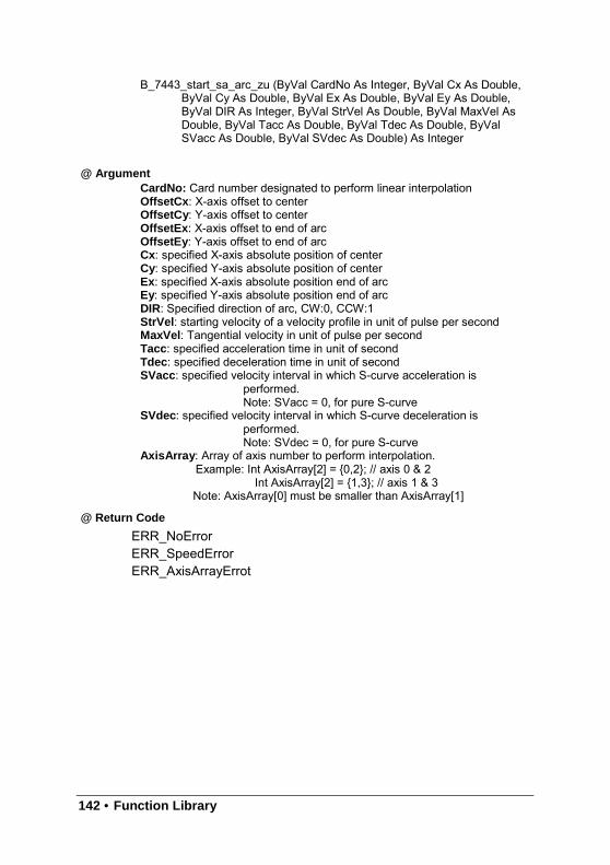
142 • Function Library
B_7443_start_sa_arc_zu (ByVal CardNo As Integer, ByVal Cx As Double,ByVal Cy As Double, ByVal Ex As Double, ByVal Ey As Double,ByVal DIR As Integer, ByVal StrVel As Double, ByVal MaxVel AsDouble, ByVal Tacc As Double, ByVal Tdec As Double, ByValSVacc As Double, ByVal SVdec As Double) As Integer
@ ArgumentCardNo: Card number designated to perform linear interpolationOffsetCx : X-axis offset to centerOffsetCy : Y-axis offset to centerOffsetEx: X-axis offset to end of arcOffsetEy : Y-axis offset to end of arcCx: specified X-axis absolute position of centerCy: specified Y-axis absolute position of centerEx: specified X-axis absolute position end of arcEy: specified Y-axis absolute position end of arcDIR: Specified direction of arc, CW:0, CCW:1StrVel : starting velocity of a velocity profile in unit of pulse per secondMaxVel : Tangential velocity in unit of pulse per secondTacc: specified acceleration time in unit of secondTdec : specified deceleration time in unit of secondSVacc: specified velocity interval in which S-curve acceleration is
performed.Note: SVacc = 0, for pure S-curve
SVdec : specified velocity interval in which S-curve deceleration isperformed.Note: SVdec = 0, for pure S-curve
AxisArray : Array of axis number to perform interpolation.Example: Int AxisArray[2] = 0,2; // axis 0 & 2
Int AxisArray[2] = 1,3; // axis 1 & 3Note: AxisArray[0] must be smaller than AxisArray[1]
@ Return Code
ERR_NoErrorERR_SpeedErrorERR_AxisArrayErrot
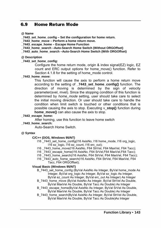
Function Library • 143
6.9 Home Return Mode
@ Name_7443_set_home_config – Set the configuration for home return._7443_home_move – Perform a home return move._7443_escape_home – Escape Home Function_7443_home_search –Auto-Search Home Switch (Without ORGOffset)_7443_auto_home_search –Auto-Search Home Switch (With ORGOffset)
@ Description_7443_set_home_config:
Configure the home return mode, origin & index signal(EZ) logic, EZcount and ERC output options for home_move() function. Refer toSection 4.1.8 for the setting of home_mode control.
_7443_home_move:This function will cause the axis to perform a home return moveaccording to the setting of _7443_set_home_config() function. Thedirection of moving is determined by the sign of velocityparameter(svel, mvel). Since the stopping condition of this function isdetermined by home_mode setting, user should take care to selectthe initial moving direction. Or user should take care to handle thecondition when limit switch is touched or other conditions that ispossible causing the axis to stop. Executing v_stop() function duringhome_move() can also cause the axis to stop.
_7443_escape_home:After homing, use this function to leave home switch
_7443_home_search:Auto-Search Home Switch.
@ Syntax
C/C++ (DOS, Windows 95/NT)I16 _7443_set_home_config(I16 AxisNo, I16 home_mode, I16 org_logic,
I16 ez_logic, I16 ez_count, I16 erc_out);I16 _7443_home_move(I16 AxisNo, F64 StrVel, F64 MaxVel, F64 Tacc);I16 _7443_escape_home(I16 AxisNo, F64 SrVel,F64 MaxVel,F64 Tacc);I16 _7443_home_search(I16 AxisNo, F64 StrVel, F64 MaxVel, F64 Tacc);I16 _7443_auto_home_search(I16 AxisNo, F64 StrVel, F64 MaxVel, F64
Tacc, F64 ORGOffset);Visual Basic (Windows 95/NT)
B_7443_set_home_config (ByVal AxisNo As Integer, ByVal home_mode AsInteger, ByVal org_logic As Integer, ByVal ez_logic As Integer,ByVal ez_count As Integer, ByVal erc_out As Integer) As Integer
B_7443_home_move (ByVal AxisNo As Integer, ByVal StrVel As Double,ByVal MaxVel As Double, ByVal Tacc As Double) As Integer
B_7443_escape_home(ByVal AxisNo As Integer, ByVal SrVel As Double,ByVal MaxVel As Double, ByVal Tacc As Double) As Integer
B_7443_home_search(ByVal AxisNo As Integer, ByVal StrVel As Double,ByVal MaxVel As Double, ByVal Tacc As Double)As Integer
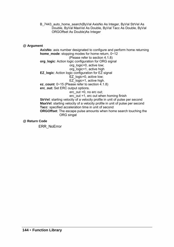
144 • Function Library
B_7443_auto_home_search(ByVal AxisNo As Integer, ByVal StrVel AsDouble, ByVal MaxVel As Double, ByVal Tacc As Double, ByValORGOffset As Double)As Integer
@ ArgumentAxisNo : axis number designated to configure and perform home returninghome_mode : stopping modes for home return, 0~12
(Please refer to section 4.1.8)org_logic : Action logic configuration for ORG signal
org_logic=0, active low;org_logic=1, active high
EZ_logic : Action logic configuration for EZ signalEZ_logic=0, active low;EZ_logic=1, active high.
ez_count : 0~15 (Please refer to section 4.1.8)erc_out: Set ERC output options.
erc_out =0, no erc out;erc_out =1, erc out when homing finish
StrVel : starting velocity of a velocity profile in unit of pulse per secondMaxVel : starting velocity of a velocity profile in unit of pulse per secondTacc: specified acceleration time in unit of secondORGOffset : The escape pulse amounts when home search touching the
ORG singal
@ Return Code
ERR_NoError
Function Library • 145
6.10 Manual Pulser Motion
@ Name_7443_set_pulser_iptmode - set the input signal modes of pulser_7443_pulser_vmove – manual pulser v_move_7443_pulser_pmove – manual pulser p_moce_7443_pulser_home_move – manual pulser home move_7443_set_pulser_ratio –Set manual pulser ratio for actual output pulse rate._7443_pulser_r_line2 –Pulser mode for 2-axis linear interpolation_7443_pulser_r_arc2 –Pulser mode for 2-axis arc interpolation
@ Description_7443_set_pulser_iptmode:
This function is used to configure the input mode of manual pulser._7443_pulser_vmove:
As this command is written, the axis begins to move the axisaccording to manual pulser input. The axis will output one pulsewhen receive one pulse from pulser, until the sd_stop or emg_stopcommand is written.
_7443_pulser_pmove:As this command is written, the axis begins to move the axisaccording to manual pulser input. The axis will output one pulsewhen receive one pulse from pulser, until the sd_stop or emg_stopcommand is written or the output pulse number reach dist.
_7443_pulser_home_move:As this command is written, the axis begins to move the axis
according to manual pulser input. The axis will output one pulse whenreceive one pulse from pulser, until the sd_stop or emg_stopcommand is written or the home move finish.
_7443_set_pulser_ratio:Set manual pulser ratio for actual output pulse rate. The formula for
pulser output rate isOutput Pulse Speed=(PA_PB Speed) * 4 * (PMG+1)*PDV/2048The PDV=0~10 Divide FactorThe PMG=0~4 Multi Factor
_7443_set_pulser_ratio:Pulser mode for 2-axis linear interpolation (relative mode only).
_7443_pulser_r_arc2:Pulser mode for 2-axis arc interpolation (relative mode only)

146 • Function Library
@ Syntax
C/C++ (DOS, Windows 95/NT)I16 _7443_set_pulser_iptmode(I16 AxisNo,I16 InputMode, I16 Inverse);I16 _7443_pulser_vmove(I16 AxisNo, F64 SpeedLimit);I16 _7443_pulser_pmove(I16 AxisNo, F64 Dist, F64 SpeedLimit);I16 _7443_pulser_home_move(I16 AxisNo, I16 HomeType, F64
SpeedLimit);I16 _7443_set_pulser_ratio(I16 AxisNo,I16 PDV, I16 PMG);I16 _7443_pulser_r_line2(I16 CardNo,I16 *AxisArray, F64 DistX, F64 DistY,
F64 SpeedLimit);I16 _7443_pulser_r_arc2(I16 CardNo, I16 *AxisArray, F64 OffsetCx, F64
OffsetCy, F64 OffsetEx, F64 OffsetEy, I16 DIR, F64 MaxVel);
Visual Basic (Windows 95/NT)B_7443_set_pulser_iptmode (ByVal AxisNo As Integer, ByVal InputMode
As Integer, ByVal Inverse As Integer) As IntegerB_7443_pulser_vmove (ByVal AxisNo As Integer, ByVal SpeedLimit As
Double) As IntegerB_7443_pulser_pmove (ByVal AxisNo As Integer, ByVal Dist As Double,
ByVal SpeedLimit As Double) As IntegerB_7443_pulser_home_move (ByVal AxisNo As Integer, ByVal HomeType
As Integer, ByVal SpeedLimit As Double) As IntegerB_7443_set_pulser_ratio(ByVal AxisNo As Integer, ByVal PDV As Integer,
ByVal PMG As Integer) As IntegerB_7443_pulser_r_line2(ByVal CardNo As Integer, AxisArray As Integer,
ByVal DistX As Double, ByVal DistY As Double, ByVal SpeedLimitAs Double) As Integer
B_7443_pulser_r_arc2(ByVal CardNo As Integer, AxisArray As Integer,ByVal OffsetCx As Double, ByVal OffsetCy As Double, ByValOffsetEx As Double, ByVal OffsetEy As Double, ByVal DIR AsInteger, ByVal MaxVel As Double) As Integer
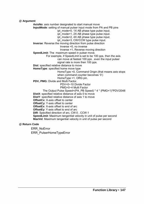
Function Library • 147
@ ArgumentAxisNo : axis number designated to start manual moveInputMode : setting of manual pulser input mode from PA and PB pins
ipt_mode=0, 1X AB phase type pulse input.ipt_mode=1, 2X AB phase type pulse input.ipt_mode=2, 4X AB phase type pulse input.ipt_mode=3, CW/CCW type pulse input.
Inverse: Reverse the moving direction from pulse directionInverse =0, no inverseInverse =1, Reverse moving direction
SpeedLimit : The maximum speed in pulser move.For example, if SpeedLimit is set to be 100 pps, then the axis
can move at fastest 100 pps , even the input pulsersignal rate is more then 100 pps.
Dist: specified relative distance to moveHomeType : specified home move type
HomeType =0, Command Origin.(that means axis stopswhen command counter becomes ‘0’)HomeType =1, ORG pin.
PDV, PMG: Divide and Multi Factor.PDV=0~10 Divide FactorPMG=0~4 Multi Factor
The Output Pulse Speed=(PA_PB Speed) * 4 * (PMG+1)*PDV/2048DistX : specified relative distance of axis 0 to moveDistY : specified relative distance of axis 1 to moveOffsetCx : X-axis offset to centerOffsetCy : Y-axis offset to centerOffsetEx: X-axis offset to end of arcOffsetEy : Y-axis offset to end of arcDIR: Specified direction of arc, CW:0 , CCW:1SpeedLimit : Maximum tangential velocity in unit of pulse per secondMaxVel : Maximum tangential velocity in unit of pulse per second
@ Return Code
ERR_NoErrorERR_PulserHomeTypeError
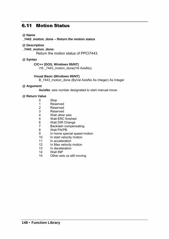
148 • Function Library
6.11 Motion Status
@ Name_7443_motion_done – Return the motion status
@ Description_7443_motion_done:
Return the motion status of PPCI7443.
@ Syntax
C/C++ (DOS, Windows 95/NT)I16 _7443_motion_done(I16 AxisNo);
Visual Basic (Windows 95/NT)B_7443_motion_done (ByVal AxisNo As Integer) As Integer
@ ArgumentAxisNo : axis number designated to start manual move
@ Return Value0 Stop1 Reserved2 Reserved3 Reserved4 Wait other axis5 Wait ERC finished6 Wait DIR Change7 Backlash compensating8 Wait PA/PB9 In home special speed motion10 In start velocity motion11 In acceleration12 In Max velocity motion13 In deceleration14 Wait INP15 Other axis us still moving
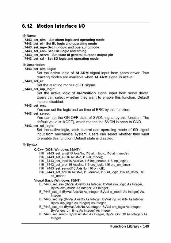
Function Library • 149
6.12 Motion Interface I/O
@ Name_7443_set_alm – Set alarm logic and operating mode_7443_set_el – Set EL logic and operating mode_7443_set_inp– Set Inp logic and operating mode_7443_set_erc– Set ERC logic and timing_7443_set_servo – Set state of general purpose output pin_7443_set_sd – Set SD logic and operating mode
@ Description_7443_set_alm_logic:
Set the active logic of ALARM signal input from servo driver. Tworeacting modes are available when ALARM signal is active.
_7443_set_el:Set the reacting modes of EL signal.
_7443_set_inp_logic:Set the active logic of In-Position signal input from servo driver.Users can select whether they want to enable this function. Defaultstate is disabled.
_7443_set_erc:You can set the logic and on time of ERC by this function.
_7443_set_servo:You can set the ON-OFF state of SVON signal by this function. Thedefault value is 1(OFF), which means the SVON is open to GND.
_7443_set_sd_logic:Set the active logic, latch control and operating mode of SD signalinput from mechanical system. Users can select whether they wantto enable this function. Default state is disabled.
@ Syntax
C/C++ (DOS, Windows 95/NT)I16 _7443_set_alm(I16 AxisNo, I16 alm_logic, I16 alm_mode);I16 _7443_set_el(I16 AxisNo, I16 el_mode);I16 _7443_set_inp(I16 AxisNo, I16 inp_enable, I16 inp_logic);I16 _7443_set_erc(I16 AxisNo, I16 erc_logic, I16 erc_on_time);I16 _7443_set_servo(I16 AxisNo, I16 on_off);I16 _7443_set_sd(I16 AxisNo, I16 enable, I16 sd_logic, I16 sd_latch, I16
sd_mode);Visual Basic (Windows 95/NT)
B_7443_set_alm (ByVal AxisNo As Integer, ByVal alm_logic As Integer,ByVal alm_mode As Integer) As Integer
B_7443_set_el (ByVal AxisNo As Integer, ByVal el_mode As Integer) AsInteger
B_7443_set_inp (ByVal AxisNo As Integer, ByVal inp_enable As Integer,ByVal inp_logic As Integer) As Integer
B_7443_set_erc (ByVal AxisNo As Integer, ByVal erc_logic As Integer,ByVal erc_on_time As Integer) As Integer
B_7443_set_servo (ByVal AxisNo As Integer, ByVal On_Off As Integer) AsInteger
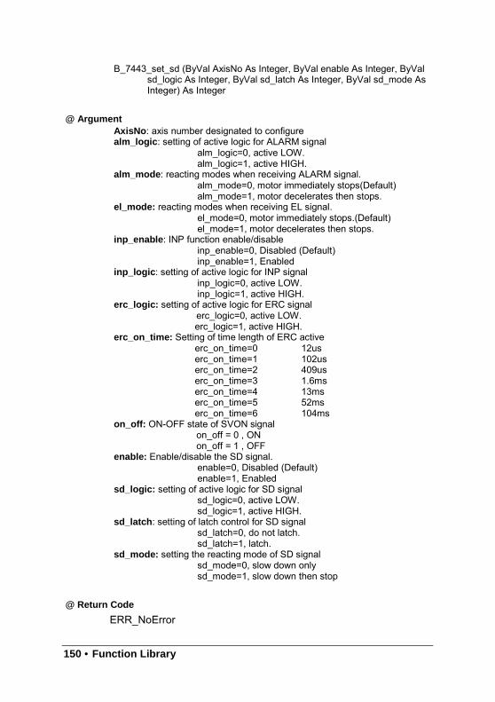
150 • Function Library
B_7443_set_sd (ByVal AxisNo As Integer, ByVal enable As Integer, ByValsd_logic As Integer, ByVal sd_latch As Integer, ByVal sd_mode AsInteger) As Integer
@ ArgumentAxisNo : axis number designated to configurealm_logic: setting of active logic for ALARM signal
alm_logic=0, active LOW.alm_logic=1, active HIGH.
alm_mode : reacting modes when receiving ALARM signal.alm_mode=0, motor immediately stops(Default)alm_mode=1, motor decelerates then stops.
el_mode: reacting modes when receiving EL signal.el_mode=0, motor immediately stops.(Default)el_mode=1, motor decelerates then stops.
inp_enable: INP function enable/disableinp_enable=0, Disabled (Default)inp_enable=1, Enabled
inp_logic : setting of active logic for INP signalinp_logic=0, active LOW.inp_logic=1, active HIGH.
erc_logic: setting of active logic for ERC signalerc_logic=0, active LOW.erc_logic=1, active HIGH.
erc_on_time: Setting of time length of ERC activeerc_on_time=0 12userc_on_time=1 102userc_on_time=2 409userc_on_time=3 1.6mserc_on_time=4 13mserc_on_time=5 52mserc_on_time=6 104ms
on_off: ON-OFF state of SVON signalon_off = 0 , ONon_off = 1 , OFF
enable: Enable/disable the SD signal.enable=0, Disabled (Default)enable=1, Enabled
sd_logic: setting of active logic for SD signalsd_logic=0, active LOW.sd_logic=1, active HIGH.
sd_latch : setting of latch control for SD signalsd_latch=0, do not latch.sd_latch=1, latch.
sd_mode: setting the reacting mode of SD signalsd_mode=0, slow down onlysd_mode=1, slow down then stop
@ Return Code
ERR_NoError
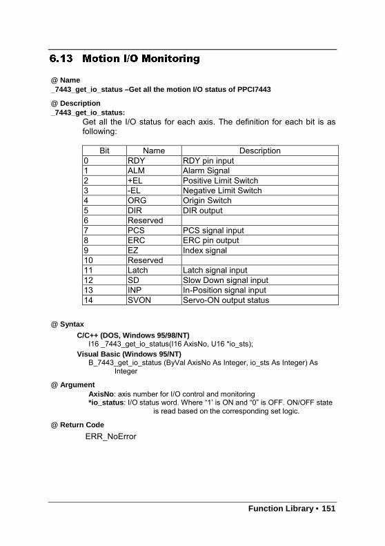
Function Library • 151
6.13 Motion I/O Monitoring
@ Name_7443_get_io_status –Get all the motion I/O status of PPCI7443
@ Description_7443_get_io_status:
Get all the I/O status for each axis. The definition for each bit is asfollowing:
Bit Name Description0 RDY RDY pin input1 ALM Alarm Signal2 +EL Positive Limit Switch3 -EL Negative Limit Switch4 ORG Origin Switch5 DIR DIR output6 Reserved7 PCS PCS signal input8 ERC ERC pin output9 EZ Index signal10 Reserved11 Latch Latch signal input12 SD Slow Down signal input13 INP In-Position signal input14 SVON Servo-ON output status
@ Syntax
C/C++ (DOS, Windows 95/98/NT)I16 _7443_get_io_status(I16 AxisNo, U16 *io_sts);
Visual Basic (Windows 95/NT)B_7443_get_io_status (ByVal AxisNo As Integer, io_sts As Integer) As
Integer
@ ArgumentAxisNo : axis number for I/O control and monitoring*io_status : I/O status word. Where “1’ is ON and “0” is OFF. ON/OFF state
is read based on the corresponding set logic.
@ Return Code
ERR_NoError
152 • Function Library
6.14 Interrupt Control
@ Name_7443_int_control – Enable/Disable INT service_7443_set_int_factor – Set INT factor_7443_int_enable – Enable event (For Window only)_7443_int_disable – Disable event (For Window only)_7443_get_int_status – Get INT Status (For Window only)_7443_link_interrupt – Set link to interrupt call back function (For Window only)_7443_get_int_type – Get INT type (For DOS only)_7443_enter_isr – Enter interrupt service routine (For DOS only)_7443_leave_isr – Leave interrupt service routine (For DOS only)_7443_get_event_int – Get event status (For DOS only)_7443_get_error_int – Get error status (For DOS only)_7443_get_irq_status – Get IRQ status (For DOS only)_7443_not_my_irq – Not My IRQ (For DOS only)_7443_isr0~9, a, b – Interrupt service routine (For DOS only)_7443_set_axis_stop_int – enable axis stop int_7443_mask_axis_stop_int – mask axis stop int
@ Description_7443_int_control:
This function is used to enable interrupt generating to host PC._7443_set_int_factor:
This function allows users to select factors to initiate the event int.The error can never be masked once the interrupt service is turn onby _7443_int_control().The int status of PPCI7443 is composed of two independent parts:error_int_status and event_int_status. The event_ int_statusrecodes the motion and comparator event under normal operation ,and this kind of INT status can be masked by_7443_set_int_factor() . The error_int_status is for abnormal stop ofPPCI7443, for example: EL, ALM …etc. This kind of INT cannot bemasked. The following is the definition of these two int_status. Bysetting the relative bit as 1, PPCI7443 can generate INT signal tohost PC.
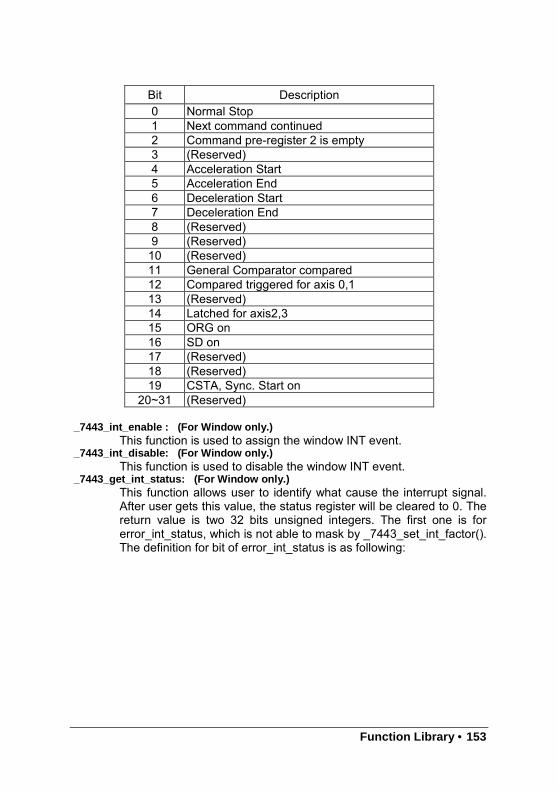
Function Library • 153
Bit Description0 Normal Stop1 Next command continued2 Command pre-register 2 is empty3 (Reserved)4 Acceleration Start5 Acceleration End6 Deceleration Start7 Deceleration End8 (Reserved)9 (Reserved)10 (Reserved)11 General Comparator compared12 Compared triggered for axis 0,113 (Reserved)14 Latched for axis2,315 ORG on16 SD on17 (Reserved)18 (Reserved)19 CSTA, Sync. Start on
20~31 (Reserved)
_7443_int_enable : (For Window only.)This function is used to assign the window INT event.
_7443_int_disable: (For Window only.)This function is used to disable the window INT event.
_7443_get_int_status: (For Window only.)This function allows user to identify what cause the interrupt signal.After user gets this value, the status register will be cleared to 0. Thereturn value is two 32 bits unsigned integers. The first one is forerror_int_status, which is not able to mask by _7443_set_int_factor().The definition for bit of error_int_status is as following:
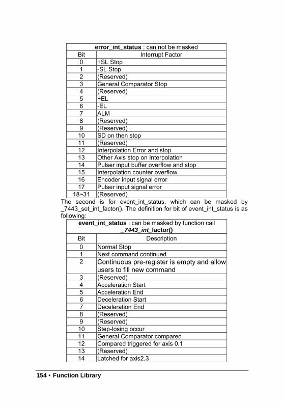
154 • Function Library
error_int_status : can not be maskedBit Interrupt Factor0 +SL Stop1 -SL Stop2 (Reserved)3 General Comparator Stop4 (Reserved)5 +EL6 -EL7 ALM8 (Reserved)9 (Reserved)10 SD on then stop11 (Reserved)12 Interpolation Error and stop13 Other Axis stop on Interpolation14 Pulser input buffer overflow and stop15 Interpolation counter overflow16 Encoder input signal error17 Pulser input signal error
18~31 (Reserved)The second is for event_int_status, which can be masked by_7443_set_int_factor(). The definition for bit of event_int_status is asfollowing:
event_int_status : can be masked by function call_7443_int_ factor()
Bit Description0 Normal Stop1 Next command continued2 Continuous pre-register is empty and allow
users to fill new command3 (Reserved)4 Acceleration Start5 Acceleration End6 Deceleration Start7 Deceleration End8 (Reserved)9 (Reserved)10 Step-losing occur11 General Comparator compared12 Compared triggered for axis 0,113 (Reserved)14 Latched for axis2,3
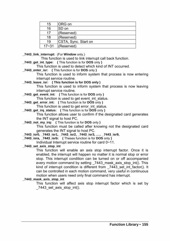
Function Library • 155
15 ORG on16 SD on17 (Reserved)18 (Reserved)19 CSTA, Sync. Start on
17~31 (Reserved)
_7443_link_interrupt: (For Window only.)This function is used to link interrupt call back function.
_7443_get_int_type: ( This function is for DOS only )This function is used to detect which kind of INT occurred.
_7443_enter_isr: ( This function is for DOS only )This function is used to inform system that process is now enteringinterrupt service routine.
_7443_leave_isr: ( This function is for DOS only )This function is used to inform system that process is now leavinginterrupt service routine.
_7443_get_event_int: ( This function is for DOS only )This function is used to get event_int_status.
_7443_get_error_int: ( This function is for DOS only )This function is used to get error_int_status.
_7443_get_irq_status: ( This function is for DOS only )This function allows user to confirm if the designated card generatesthe INT signal to host PC.
_7443_not_my_irq: ( This function is for DOS only )This function must be called after knowing not the designated cardgenerates the INT signal to host PC.
_7443_isr0, _7443_isr1, _7443_isr2, _7443_isr3, ….. _7443_isr9,_7443_isra, _7443_isrb: ( Theses function is for DOS only )
Individual Interrupt service routine for card 0~11._7443_set_axis_stop_int
This function will enable an axis stop interrupt factor. Once it isenabled, the interrupt will happen no matter it is normal stop or errorstop. This interrupt condition can be turned on or off accompaniedevery motion command by setting _7443_mask_axis_stop_int(). Thiskind of interrupt condition is different from _7443_set_int_factor(). Itcan be controlled in each motion command, very useful in continuousmotion when users need only final command has interrupt.
_7443_mask_axis_stop_intThis function will affect axis stop interrupt factor which is set by_7443_set_axis_stop_int().
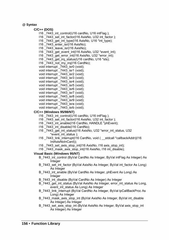
156 • Function Library
@ Syntax
C/C++ (DOS)I16 _7443_int_control(U16 cardNo, U16 intFlag );I16 _7443_set_int_factor(I16 AxisNo, U32 int_factor );I16 _7443_get_int_type(I16 AxisNo, U16 *int_type);I16 _7443_enter_isr(I16 AxisNo);I16 _7443_leave_isr(I16 AxisNo);I16 _7443_get_event_int(I16 AxisNo, U32 *event_int);I16 _7443_get_error_int(I16 AxisNo, U32 *error_int);I16 _7443_get_irq_status(U16 cardNo, U16 *sts);I16 _7443_not_my_irq(I16 CardNo);void interrupt _7443_isr0 (void);void interrupt _7443_isr1 (void);void interrupt _7443_isr2 (void);void interrupt _7443_isr3 (void);void interrupt _7443_isr4 (void);void interrupt _7443_isr5 (void);void interrupt _7443_isr6 (void);void interrupt _7443_isr7 (void);void interrupt _7443_isr8 (void);void interrupt _7443_isr9 (void);void interrupt _7443_isra (void);void interrupt _7443_isrb (void);
C/C++ (Windows 95/98/NT)I16 _7443_int_control(U16 cardNo, U16 intFlag );I16 _7443_set_int_factor(I16 AxisNo, U32 int_factor );I16 _7443_int_enable(I16 CardNo, HANDLE *phEvent);I16 _7443_int_disable(I16 CardNo);I16 _7443_get_int_status(I16 AxisNo, U32 *error_int_status, U32
*event_int_status );I16 _7443_link_interrupt(I16 CardNo, void ( __stdcall *callbackAddr)(I16
IntAxisNoInCard));I16 _7443_set_axis_stop_int(I16 AxisNo, I16 axis_stop_int);I16 _7443_mask_axis_stop_int(I16 AxisNo, I16 int_disable);
Visual Basic (Windows 95/NT)B_7443_int_control (ByVal CardNo As Integer, ByVal intFlag As Integer) As
IntegerB_7443_set_int_factor (ByVal AxisNo As Integer, ByVal int_factor As Long)
As IntegerB_7443_int_enable (ByVal CardNo As Integer, phEvent As Long) As
IntegerB_7443_int_disable (ByVal CardNo As Integer) As IntegerB_7443_get_int_status (ByVal AxisNo As Integer, error_int_status As Long,
event_int_status As Long) As IntegerB_7443_link_interrupt (ByVal CardNo As Integer, ByVal lpCallBackProc As
Long) As IntegerB_7443_mask_axis_stop_int (ByVal AxisNo As Integer, ByVal int_disable
As Integer) As IntegerB_7443_set_axis_stop_int (ByVal AxisNo As Integer, ByVal axis_stop_int
As Integer) As Integer
Function Library • 157
@ ArgumentcardNo : card number 0,1,2,3…AxisNo : axis number 0,1,2,3,4…intFlag : int flag, 0 or 1 (0: Disable, 1:Enable)int_factor : interrupt factor, refer to previous table*int_type: Interrupt type, (1: error int, 2: event int, 3: both happened )*event_int: event_int_status, , refer to previous table*error_int: error_int_status, refer to previous table*sts: (0: not this card’s IRQ, 1: this card’s IRQ)*phEvent: event handler (Windows)*error_int_status : refer to previous table*event_int_status: refer to previous tableint_disable : (0:make axis stop interrupt active, 1:make axis stop interrupt
in-active)axis_stop_int: (0: disable axis stop interrupt factor, 1: enable axis stop
interrupt factor )
@ Return Code
ERR_NoErrorERR_EventNotEnableYetERR_LinkIntErrorERR_CardNoErrot
158 • Function Library
6.15 Position Control and Counters
@ Name_7443_get_position – Get the value of feedback position counter_7443_set_position – Set the feedback position counter_7443_get_command – Get the value of command position counter_7443_set_command – Set the command position counter_7443_get_error_counter – Get the value of position error counter_7443_reset_error_counter – Reset the position error counter_7443_get_general_counter – Get the value of general counter_7443_set_general_counter – Set the general counter_7443_get_target_pos – Get the value of target position recorder_7443_reset_target_pos – Reset target position recorder_7443_get_rest_command – Get remaining pulse till end of motion_7443_check_rdp – Get the ramping down point data
@ Description_7443_get_position():
This function is used to read the value of feedback position counter.Note, this value has already been processed by move ratio. If moveratio is 0.5, than the value read will be twice as the counter value.The source of feedback counter is selectable by function_7443_set_feedback_src() to be external EA/EB or pulse output ofPPCI7443.
_7443_set_position():This function is used to change the feedback position counter to thespecified value. Note, the value to be set will be processed by moveratio. If move ratio is 0.5, than the set value will be twice as givenvalue.
_7443_get_command():This function is used to read the value of command position counter.The source of command position counter is the pulse output ofPPCI7443.
_7443_set_command():This function is used to change the value of command positioncounter.
_7443_get_error_counter():This function is used to read the value of position error counter.
_7443_reset_error_counter():This function is used to clear position error counter.
_7443_get_general_counter():This function is used to read the value of general counter.
_7443_set_general_counter():This function is used to set the counting source of and change thevalue of general counter. (By default, the source is pulser input.)
Function Library • 159
_7443_get_target_pos():This function is used to read the value of target position recorder.The target position recorder is maintained by PPCI7443 softwaredriver. It records the position to settle down for current runningmotion.
_7443_reset_target_pos():This function is used to set new value for target position recorder. Itis necessary to call this function when home return completion orwhen new feedback counter value is set by function_7443_set_position().
_7443_get_rest_command():This function is used to read remaining pulse counts till end ofcurrent motion.
_7443_check_rdp():This function is used to read the ramping down point data. Theramping down point is the position where deceleration starts. Thedata is stored as pulse count, and it cause the axis start todecelerate when remaining pulse count reach the data.
@ Syntax
C/C++ (DOS, Windows 95/98/NT)I16 _7443_get_position(I16 AxisNo, F64 *pos);I16 _7443_set_position(I16 AxisNo, F64 pos);I16 _7443_get_command(I16 AxisNo, I32 *cmd);I16 _7443_set_command(I16 AxisNo, I32 cmd);I16 _7443_get_error_counter(I16 AxisNo, I16 *error_counter);I16 _7443_reset_error_counter(I16 AxisNo);I16 _7443_get_general_counter(I16 AxisNo, F64 *CntValue);I16 _7443_set_general_counter(I16 AxisNo,I16 CntSrc, F64 CntValue);I16 _7443_get_target_pos(I16 AxisNo, F64 *T_pos);I16 _7443_reset_target_pos(I16 AxisNo, F64 T_pos);I16 _7443_get_rest_command(I16 AxisNo, I32 *rest_command);I16 _7443_check_rdp(I16 AxisNo, I32 *rdp_command);
160 • Function Library
Visual Basic (Windows 95/NT)B_7443_get_position (ByVal AxisNo As Integer, Pos As Double) As IntegerB_7443_set_position (ByVal AxisNo As Integer, ByVal Pos As Double) As
IntegerB_7443_get_command (ByVal AxisNo As Integer, cmd As Long) As IntegerB_7443_set_command (ByVal AxisNo As Integer, ByVal cmd As Long) As
IntegerB_7443_get_error_counter (ByVal AxisNo As Integer, error_counter As
Integer) As IntegerB_7443_reset_error_counter (ByVal AxisNo As Integer) As IntegerB_7443_get_general_counter (ByVal AxisNo As Integer, CntValue As
Double) As IntegerB_7443_set_general_counter (ByVal AxisNo As Integer, ByVal CntSrc As
Integer, ByVal CntValue As Double) As IntegerB_7443_get_target_pos (ByVal AxisNo As Integer, Pos As Double) As
IntegerB_7443_reset_target_pos (ByVal AxisNo As Integer, ByVal Pos As Double)
As IntegerB_7443_get_rest_command (ByVal AxisNo As Integer, rest_command As
Long) As IntegerB_7443_check_rdp (ByVal AxisNo As Integer, rdp_command As Long) As
Integer
@ ArgumentAxisNo : Axis numberPos, *Pos: Feedback position counter value,
range: -134217728~134217727cmd, *cmd: Command position counter value,
range: -134217728~134217727error_counter, *error_counter: Position error counter value,
range: -32768~32767T_pos, *T_pos: Target position recorder value,
T_ range: -134217728~134217727CntValue, * CntValue: General counter value,
range: -134217728~134217727rest_command, *rest_command: Rest pulse count till end,
range: -134217728~134217727rdp_command, *rdp_command: Ramping down point data
range: 0~167777215CntSrc: Source of general counter
0 : command1: EA/EB2: PA/PB (Default)3: CLK/2
@ Return Code
ERR_NoErrorERR_PosOutofRange
Function Library • 161
6.16 Position Compare and Latch
@ Name_7443_set_ltc_logic – Set the LTC logic_7443_get_latch_data – Get latched counter data_7443_set_soft_limit – Set soft limit_7443_enable_soft_limit – Enable soft limit function_7443_disable_soft_limit – Disable soft limit function_7443_set_error_counter_check – Step-losing detection setup_7443_set_general_comparator – Set general-purposed comparator_7443_set_trigger_comparator – Set trigger comparator_7443_set_trigger_type – Set the trigger output type_7443_check_compare_data – Check current comparator data_7443_check_compare_status – Check current comparator status_7443_set_auto_compare – Set comparing data source for auto loading_7443_build_compare_function – Build compare data via constant interval_7443_build_compare_table – Build compare data via compare table_7443_cmp_v_change – Speed change by comparator_7443_set_enable_inp – Set latch signal
@ Description_7443_set_ltc_logic():
This function is used to set the logic of latch input. This function isapplicable only for last two axes in every PPCI7443 card.
_7443_get_latch_data():After the latch signal arrived, this function is used to read the latchedvalue of counters.
_7443_set_soft_limit ():This function is used to set the value of soft limit.
_7443_enable_soft_limit (),_7443_disable_soft_limit() :These two functions are used to enable/disable the soft limit function.Once enabled, the action of soft limit will be exactly the same asphysical limit.
_7443_set_error_counter_check() :This function is used to enable the step losing checking facility. Bygiving an tolerance value, the PPCI7443 will generate an interrupt(event_int_status , bit 10) when position error counter exceedtolerance.
_7443_set_general_comparator ():This function is used to set the source and comparing value forgeneral comparator. When the source counter value reached thecomparing value, the PPCI7443 will generate an interrupt(event_int_status , bit 11).
_7443_set_trigger_comparator():This function is used to set the comparing method and value fortrigger comparator. When the feedback position counter valuereached the comparing value, the PPCI7443 will generate trigger a
162 • Function Library
pulse output via CMP and an interrupt (event_int_status , bit 12) willalso be sent to host PC. If _7443_set_auto_compare is used, thencomparing value set by this function will be ignored automatically.Note: it is applicable only for first two axes in every PPCI7443 card.
_7443_set_trigger_type():This function is used to set the trigger output mode.In hardware A2 version, it is used for setting the output pulse as oneshot or constant on.In hardware A3 version, it is used for setting the output pulse asnormal high or normal low.
_7443_check_compare_data():This function is used to get current comparing data of designatedcomparator.
_7443_check_compare_status():This function is used to get status of all comparator. When somecomparator comes into existence, the relative bit of cmp_sts willbecome ‘1’, otherwise ‘0’.
_7443_set_auto_compare():This function is used to set the comparing data source of triggercomparator. The source can be either a function or a table.
_7443_build_compare_function():This function is used to build comparing function by defining the start/ end point and interval. There is no limitation on the max number ofcomparing data. It will automatically load a final point after user’s endpoint. That is (end point + Interval x total points ) x move ratioNote: Please turn off all interrupt function, when triggering isrunning.
_7443_build_compare_table():This function is used to build comparing table by defining data array.The size of array is limited to 1024, when using RAM mode.Note: Please turn off all interrupt function, when triggering isrunning.
_7443_cmp_v_change():This function is used to setup comparator velocity change function. Itis in fact a V_change function but acts when general comparatorcomes into existence. When this function is issued, the parameter“CmpAction” of _7443_set_general_comparator() must be set ‘3’.The compare data is also set by _7443_set_general_comparator() .While, the remain distance, the compare point’s velocity , the newvelocity and the acceleration time are set by_7443_cmp_v_change() .
_7443_set_enable_inp():This function is used to setup latched signal
Function Library • 163
@ Syntax
C/C++ (DOS, Windows 95/98/NT)I16 _7443_set_ltc_logic(I16 AxisNo_2or3, I16 ltc_logic);I16 _7443_get_latch_data(I16 AxisNo, I16 LatchNo, F64 *Pos);I16 _7443_set_soft_limit(I16 AxisNo, I32 PLimit, I32 NLimit);I16 _7443_disable_soft_limit(I16 AxisNo);I16 _7443_enable_soft_limit(I16 AxisNo, I16 Action);I16 _7443_set_error_counter_check(I16 AxisNo, I16 Tolerance, I16
On_Off);I16 _7443_set_general_comparator(I16 AxisNo, I16 CmpSrc, I16
CmpMethod, I16 CmpAction, F64 Data);I16 _7443_set_trigger_comparator(I16 AxisNo, I16 CmpSrc, I16
CmpMethod, F64 Data);I16 _7443_set_trigger_type(I16 AxisNo, I16 TriggerType);I16 _7443_check_compare_data(I16 AxisNo, I16 CompType, F64 *Pos);I16 _7443_check_compare_status(I16 AxisNo, U16 *cmp_sts);I16 _7443_set_auto_compare(I16 AxisNo ,I16 SelectSrc);I16 _7443_cmp_v_change(I16 AxisNo, F64 Res_dist, F64 oldvel, F64
newvel, F64 AccTime)I16 _7443_set_enable_inp(I16 AxisNo, I16 inp_enable);
C/C++ (Windows 95/98/NT)I16 _7443_build_compare_function(I16 AxisNo, F64 Start, F64 End, F64
Interval, I16 Device);I16 _7443_build_compare_table(I16 AxisNo, F64 *TableArray, I32 Size, I16
Device);C/C++ (Dos)
I16 _7443_build_compare_function(I16 AxisNo, F64 Start, F64 End, F64Interval);
I16 _7443_build_compare_table(I16 AxisNo, F64 *TableArray, I16 Size);Visual Basic (Windows 95/NT)
B_7443_set_ltc_logic (ByVal AxisNo As Integer, ByVal ltc_logic As Integer)As Integer
B_7443_get_latch_data (ByVal AxisNo As Integer, ByVal Counter AsInteger, Pos As Double) As Integer
B_7443_set_soft_limit (ByVal AxisNo As Integer, ByVal PLimit As Long,ByVal NLimit As Long) As Integer
B_7443_disable_soft_limit (ByVal AxisNo As Integer) As IntegerB_7443_enable_soft_limit (ByVal AxisNo As Integer, ByVal Action As
Integer) As IntegerB_7443_set_error_counter_check (ByVal AxisNo As Integer, ByVal
Tolerance As Integer, ByVal On_Off As Integer) As IntegerB_7443_set_general_comparator (ByVal AxisNo As Integer, ByVal CmpSrc
As Integer, ByVal CmpMethod As Integer, ByVal CmpAction AsInteger, ByVal Data As Double) As Integer
B_7443_set_trigger_comparator (ByVal AxisNo As Integer, ByVal CmpSrcAs Integer, ByVal CmpMethod As Integer, ByVal Data As Double)As Integer
B_7443_set_trigger_type (ByVal AxisNo As Integer, ByVal TriggerType AsInteger) As Integer
B_7443_check_compare_data (ByVal AxisNo As Integer, ByValCompType As Integer, Pos As Double) As Integer
164 • Function Library
B_7443_check_compare_status (ByVal AxisNo As Integer, cmp_sts AsInteger) As Integer
B_7443_set_auto_compare (ByVal AxisNo As Integer, ByVal SelectSrc AsInteger) As Integer
B_7443_build_compare_function (ByVal AxisNo As Integer, ByVal Start AsDouble, ByVal End As Double, ByVal Interval As Double, ByValDevice As Integer) As Integer
B_7443_build_compare_table (ByVal AxisNo As Integer, TableArray AsDouble, ByVal Size As Long, ByVal Device As Integer) As Integer
B_7443_cmp_v_change(ByVal AxisNo, ByVal Res_dist as Double, ByValoldvel as Double, ByVal newvel as Double, ByVal AccTime asDouble)
B_7443_set_enable_inp (ByVal AxisNo As Integer, ByVal inp_enable AsInteger) As Integer
@ ArgumentAxisNo_2or3 : Axis number, for last two axes in one cardltc_logic: 0 means active low, 1 means active highAxisNo: Axis numberLatchNo or Counter: Specified Counter to latch
Counter = 1 , Command counterCounter = 2 , Feedback counterCounter = 3 , Error CounterCounter = 4 , General Counter
Pos: Latched counter value,PLimit: Soft limit value in positive directionNLimit: Soft limit value in negative directionAction: The reacting method of soft limit
Action =0, INT onlyAction =1, Immediately stopAction =2, slow down then stopAction =3, reserved
Tolerance: The tolerance of step-losing detectionOn_Off: Enable / Disable step-losing detection
On_Off =0, DisableOn_Off =1, Enable
CmpSrc: The comparing source counterCmpSrc =0, Command CounterCmpSrc =1, Feedback CounterCmpSrc =2, Error CounterCmpSrc =3, General Counter
CmpMethod: The comparing methodCmpMethod =0, No compareCmpMethod =1, CmpValue=Counter (Directionless)CmpMethod =2, CmpValue=Counter (+Dir)CmpMethod =3, CmpValue=Counter (-Dir)CmpMethod =4, CmpValue>CounterCmpMethod =5, CmpValue<Counter
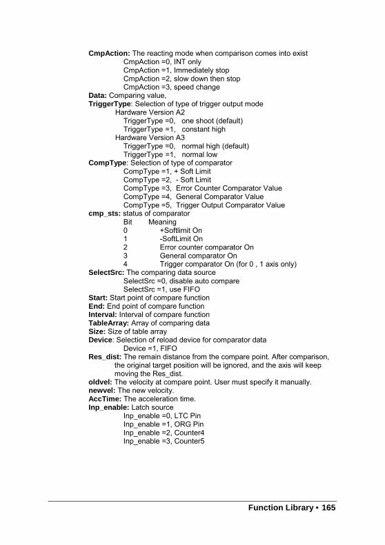
Function Library • 165
CmpAction: The reacting mode when comparison comes into existCmpAction =0, INT onlyCmpAction =1, Immediately stopCmpAction =2, slow down then stopCmpAction =3, speed change
Data: Comparing value,TriggerType : Selection of type of trigger output mode
Hardware Version A2TriggerType =0, one shoot (default)TriggerType =1, constant high
Hardware Version A3TriggerType =0, normal high (default)TriggerType =1, normal low
CompType : Selection of type of comparatorCompType =1, + Soft LimitCompType =2, - Soft LimitCompType =3, Error Counter Comparator ValueCompType =4, General Comparator ValueCompType =5, Trigger Output Comparator Value
cmp_sts: status of comparatorBit Meaning0 +Softlimit On1 -SoftLimit On2 Error counter comparator On3 General comparator On4 Trigger comparator On (for 0 , 1 axis only)
SelectSrc: The comparing data sourceSelectSrc =0, disable auto compareSelectSrc =1, use FIFO
Start: Start point of compare functionEnd: End point of compare functionInterval: Interval of compare functionTableArray: Array of comparing dataSize: Size of table arrayDevice: Selection of reload device for comparator data
Device =1, FIFORes_dist: The remain distance from the compare point. After comparison,
the original target position will be ignored, and the axis will keepmoving the Res_dist.
oldvel: The velocity at compare point. User must specify it manually.newvel: The new velocity.AccTime: The acceleration time.Inp_enable: Latch source
Inp_enable =0, LTC PinInp_enable =1, ORG PinInp_enable =2, Counter4Inp_enable =3, Counter5
166 • Function Library
@ Return Code
ERR_NoErrorERR_CompareNoErrorERR_CompareMethodErrorERR_CompareAxisErrorERR_CompareTableSizeErrorERR_CompareFunctionErrorERR_CompareTableNotReadyERR_CompareLineNotReadyERR_HardwareCompareAxisWrongERR_AutocompareSourceWrongERR_CompareDeviceTypeError
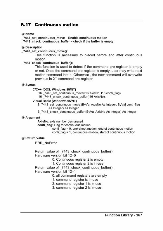
Function Library • 167
6.17 Continuous motion
@ Name_7443_set_continuous_move – Enable continuous motion_7443_check_continuous_buffer – check if the buffer is empty
@ Description_7443_set_continuous_move():
This function is necessary to placed before and after continuousmotion.
_7443_check_continuous_buffer():This function is used to detect if the command pre-register is emptyor not. Once the command pre-register is empty, user may write nextmotion command into it. Otherwise , the new command will overwriteprevious in 2nd command pre-register.
@ Syntax
C/C++ (DOS, Windows 95/NT)I16 _7443_set_continuous_move(I16 AxisNo, I16 conti_flag);I16 _7443_check_continuous_buffer(I16 AxisNo);
Visual Basic (Windows 95/NT)B_7443_set_continuous_move (ByVal AxisNo As Integer, ByVal conti_flag
As Integer) As IntegerB_7443_check_continuous_buffer (ByVal AxisNo As Integer) As Integer
@ ArgumentAxisNo : axis number designatedconti_flag : Flag for continuous motion
conti_flag = 0, one-shoot motion, end of continuous motionconti_flag = 1, continuous motion, start of continuous motion
@ Return Value
ERR_NoError
Return value of _7443_check_continuous_buffer():Hardware version bit 12=0
0: Continuous register 2 is empty1: Continuous register 2 is in-use
Return value of _7443_check_continuous_buffer():Hardware version bit 12=1
0: all command registers are empty1: command register is in-use2: command register 1 is in-use3: command register 2 is in-use
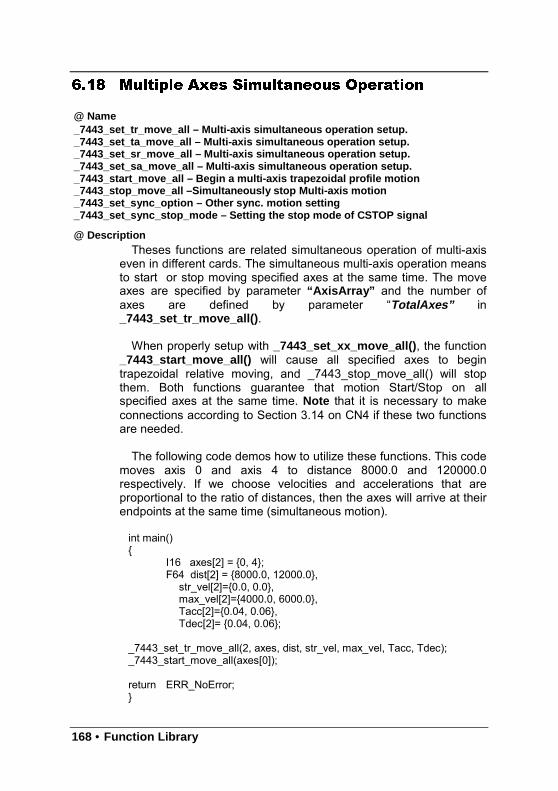
168 • Function Library
6.18 Multiple Axes Simultaneous Operation
@ Name_7443_set_tr_move_all – Multi-axis simultaneous operation setup._7443_set_ta_move_all – Multi-axis simultaneous operation setup._7443_set_sr_move_all – Multi-axis simultaneous operation setup._7443_set_sa_move_all – Multi-axis simultaneous operation setup._7443_start_move_all – Begin a multi-axis trapezoidal profile motion_7443_stop_move_all –Simultaneously stop Multi-axis motion_7443_set_sync_option – Other sync. motion setting_7443_set_sync_stop_mode – Setting the stop mode of CSTOP signal
@ DescriptionTheses functions are related simultaneous operation of multi-axis
even in different cards. The simultaneous multi-axis operation meansto start or stop moving specified axes at the same time. The moveaxes are specified by parameter “AxisArray” and the number ofaxes are defined by parameter “TotalAxes” in_7443_set_tr_move_all() .
When properly setup with _7443_set_xx_move_all() , the function_7443_start_move_all() will cause all specified axes to begintrapezoidal relative moving, and _7443_stop_move_all() will stopthem. Both functions guarantee that motion Start/Stop on allspecified axes at the same time. Note that it is necessary to makeconnections according to Section 3.14 on CN4 if these two functionsare needed.
The following code demos how to utilize these functions. This codemoves axis 0 and axis 4 to distance 8000.0 and 120000.0respectively. If we choose velocities and accelerations that areproportional to the ratio of distances, then the axes will arrive at theirendpoints at the same time (simultaneous motion).
int main()
I16 axes[2] = 0, 4;F64 dist[2] = 8000.0, 12000.0,
str_vel[2]=0.0, 0.0,max_vel[2]=4000.0, 6000.0,Tacc[2]=0.04, 0.06,Tdec[2]= 0.04, 0.06;
_7443_set_tr_move_all(2, axes, dist, str_vel, max_vel, Tacc, Tdec);_7443_start_move_all(axes[0]);
return ERR_NoError;
Function Library • 169
_7443_set_sync_option()
It has many functions. It lets two or more different command groups start atthe same time. For example, if you want a 2-axis linear interpolation and a1-axis single motion start at the same time, you can turn on this optionbefore command starts. This function also can be used on waiting anothercommand’s finish signal then start. For example, axis1 must start after axis2is done.
_7443_set_sync_stop_mode()
It has two option for stop types: One is immediately stop and the other isslow down to stop. When the _7443_stop_move_all() or CSTOP signal isused, the axes will stop according to this setting.
@ Syntax
C/C++ (DOS, Windows 95/NT)I16 _7443_set_tr_move_all(I16 TotalAxes, I16 *AxisArray, F64 *DistA, F64
*StrVelA, F64 *MaxVelA, F64 *TaccA, F64 *TdecA);I16 _7443_set_sa_move_all(I16 TotalAx, I16 *AxisArray, F64 *PosA, F64
*StrVelA, F64 *MaxVelA, F64 *TaccA, F64 *TdecA, F64 *SVaccA,F64 *SVdecA);
I16 _7443_set_ta_move_all(I16 TotalAx, I16 *AxisArray, F64 *PosA, F64*StrVelA, F64 *MaxVelA, F64 *TaccA, F64 *TdecA);
I16 _7443_set_sr_move_all(I16 TotalAx, I16 *AxisArray, F64 *DistA, F64*StrVelA, F64 *MaxVelA, F64 *TaccA, F64 *TdecA, F64 *SVaccA,F64 *SVdecA);
I16 _7443_start_move_all(I16 FirstAxisNo);I16 _7443_stop_move_all(I16 FirstAxisNo);I16 _7443_set_sync_option(I16 AxisNo, I16 sync_stop_on, I16
cstop_output_on, I16 sync_option1, I16 sync_option2);I16 _7443_set_sync_stop_mode(I16 AxisNo, I16 stop_mode);
Visual Basic (Windows 95/NT)B_7443_set_tr_move_all(ByVal TotalAxes As Integer, AxisArray As Integer,
DistA As Double, StrVelA As double, MaxVelA As double, TaccA Asdouble, TdecA As double);
B_7443_set_sa_move_all(ByVal TotalAxes As Integer, AxisArray AsInteger, PosA As Double, StrVelA As double, MaxVelA As double,TaccA As double, TdecA As double, SVaccA As double, SVdecAAs Double);
B_7443_set_ta_move_all(ByVal TotalAxes As Integer, AxisArray As Integer,PosA As Double, StrVelA As double, MaxVelA As double, TaccA Asdouble, TdecA As double);
B_7443_set_sr_move_all(ByVal TotalAxes As Integer, AxisArray As Integer,DistA As Double, StrVelA As double, MaxVelA As double, TaccA Asdouble, TdecA As double, SVaccA As double, SVdecA As Double);
B_7443_start_move_all(ByVal FirstAxisNo As Integer);B_7443_stop_move_all(ByVal FirstAxisNo As Integer);B_7443_set_sync_option (ByVal AxisNo As Integer, ByVal sync_stop_on
As Integer, ByVal cstop_output_on As Integer, ByVal sync_option1As Integer, ByVal sync_option2 As Integer) As Integer
170 • Function Library
B_7443_set_sync_stop_mode (ByVal AxisNo As Integer, ByVal stop_modeAs Integer) As Integer
@ ArgumentTotalAxes : number of axes for simultaneous motion, 1~48.* AxisArray : specified axes number array designated to move.* DistA : specified position array in unit of pulse* StrVelA: starting velocity array in unit of pulse per second* MaxVelA : maximum velocity array in unit of pulse per second* TaccA: acceleration time array in unit of second* TdecA: deceleration time array in unit of second* SVaccA : specified velocity interval array in which S-curve acceleration is
performed.* SVdecA : specified velocity interval array in which S-curve deceleration is
performed.FirstAxisNo : the first element in AxisArray.Sync_stop_on : Axis will stop if the CSTOP singal is onCstop_output_on : CSTOP singal will output when abnormal stop
(ALM,EL..etc)Sync_option1 : Choose command start type
0: default ( immediately start )1: waiting _7443_start_move_all() or CSTA singal2: Reserved3: Check Sync_option2’s condition to start
Sync_option2 : for example0: default ( useless )1: after Axis0 stops2: after Axis1 stops4: after Axis2 stops8: after Axis3 stops5: after Axis0 and Axis2 stop15: Axis0~Axis3 stop
stop_mode : 0: immediately stop1: slow down to stop
@ Return Code
ERR_NoErrorERR_SpeedError
Function Library • 171
6.19 General-purposed TTL output
@ Name_7443_d_output – Digital Output_7443_get_dio_status – Get DIO status
@ Description_7443_d_output():
Set the on_off status for general-purposed TTL Digital output pin._7443_get_dio_status():
Read status of all digital output pin.
@ Syntax
C/C++ (DOS, Windows 95/NT)I16 _7443_d_output(I16 CardNo, I16 Ch_No, I16 value);I16 _7443_get_dio_status(I16 CardNo, U16 *dio_sts);
Visual Basic (Windows 95/NT)B_7443_d_output (ByVal CardNo As Integer, ByVal Ch_No As Integer,
ByVal value As Integer) As IntegerB_7443_get_dio_status (ByVal CardNo As Integer, dio_sts As Integer) As
Integer
@ ArgumentCardNo : Designated card numberCh_No: Designated channel number 0~5Value: On-Off Value for output
Value =0, output OFFValue =1, output ON
dio_status: Digital output statusbit0~bit5 for channel 0~5 , respectively
@ Return Value
ERR_NoErrorERR_DioNoError
172 • Connection Example
7
Connection Example
This chapter shows some connection examples between PPCI7443 andservo drivers and stepping drivers.
7.1 General Description of Wiring
CN1: Receives +24V power from external power supply.
CN2 :Main connection between PPCI7443 and pulse input servo driver orstepping driver.
CN3: Receive pulse command from manual pulser.
CN4: Connector for simultaneously start or stop multiple PPCI7443 cards.
CN5: TTL digital output.
Figure 7.1 shows how to integrate PPCI7443 with a physical system.
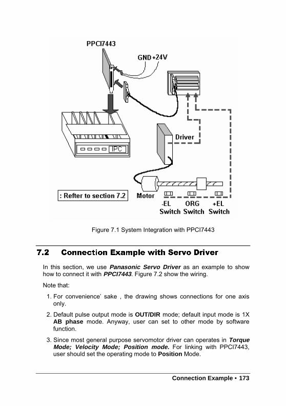
Connection Example • 173
Figure 7.1 System Integration with PPCI7443
7.2 Connection Example with Servo Driver
In this section, we use Panasonic Servo Driver as an example to showhow to connect it with PPCI7443. Figure 7.2 show the wiring.
Note that:
1. For convenience’ sake , the drawing shows connections for one axisonly.
2. Default pulse output mode is OUT/DIR mode; default input mode is 1XAB phase mode. Anyway, user can set to other mode by softwarefunction.
3. Since most general purpose servomotor driver can operates in TorqueMode; Velocity Mode; Position mode. For linking with PPCI7443,user should set the operating mode to Position Mode.
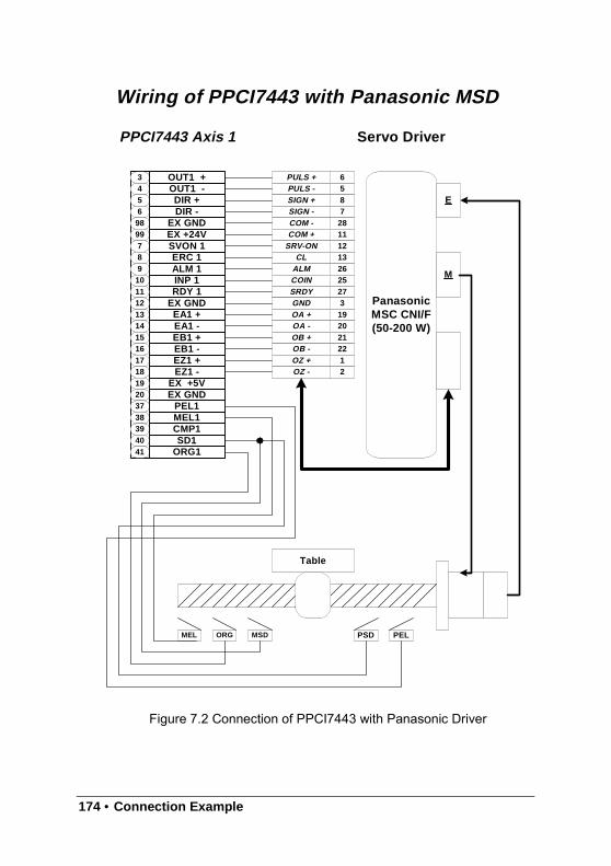
174 • Connection Example
Figure 7.2 Connection of PPCI7443 with Panasonic Driver
Wiring of PPCI7443 with Panasonic MSD
3456
9899789
10
131415161718
203738394041
OUT1 +OUT1 -DIR +DIR -
EX GNDEX +24VSVON 1ERC 1ALM 1INP 1
EA1 +EA1 -EB1 +EB1 -EZ1 +EZ1 -
EX GNDPEL1MEL1CMP1SD1
ORG1
RDY 1EX GND
1112
EX +5V19
PPCI7443 Axis 1 Servo Driver
PanasonicMSC CNI/F(50-200 W)
Table
MEL ORG MSD PSD PEL
E
M
6587
PULS +PULS -SIGN +SIGN -
281112
COM -COM +
SRV-ON
2625
ALMCOIN
27SRDY3
19GNDOA +
20OA -2122
OB +OB -
1OZ +2OZ -
13CL
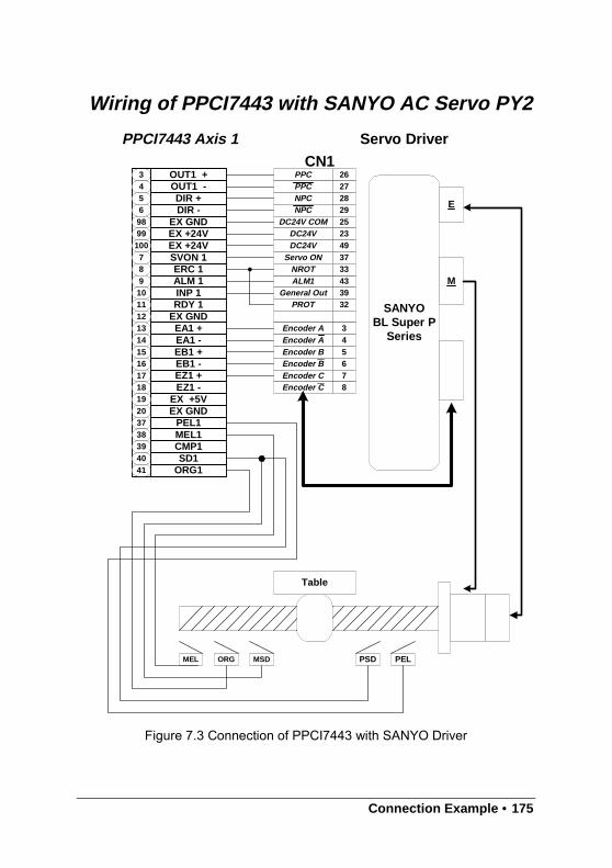
Connection Example • 175
Figure 7.3 Connection of PPCI7443 with SANYO Driver
Wiring of PPCI7443 with SANYO AC Servo PY2
34569899
78910
131415161718
203738394041
OUT1 +OUT1 -DIR +DIR -
EX GNDEX +24V
SVON 1ERC 1ALM 1INP 1
EA1 +EA1 -EB1 +EB1 -EZ1 +EZ1 -
EX GNDPEL1MEL1CMP1SD1
ORG1
RDY 1EX GND
1112
EX +5V19
PPCI7443 Axis 1 Servo Driver
SANYOBL Super P
Series
Table
MEL ORG MSD PSD PEL
E
M
26272829
PPCPPCNPCNPC
2523
37
DC24V COMDC24V
Servo ON
4339
ALM1General Out
32PROT
3Encoder A4Encoder A56
Encoder BEncoder B
7Encoder C8Encoder C
33NROT
CN1
EX +24V100 49DC24V