Embed Size (px)
Citation preview

INSTRUCTIONSFOR
SPRUE PICKER
© copyright 2007
MODEL NO.
SERIAL NO.
www.ppe.com • e-mail: [email protected]
8303 CORPORATE PARK DRIVE, MACEDONIA (Cleveland), OHIO 44056, USA216-367-7000 • Toll Free: 800-321-0562 • Fax: 216-367-7022 • Order Fax: 800-223-8305
6385 Montessouri Street, Las Vegas, Nevada 89113
702-433-6385 • 800-258-8877 • Fax: 702-433-6388PPEW E S T
PPES O U T H
11218 Challenger Avenue, Odessa, Florida 33556
727-834-8888 • 800-282-6783 • Fax: 727-834-8873
Toll Free: USA, Canada & Mexico
800-362-0706
PLASTIC PROCESS EQUIPMENT, INC.
PPE

A. Getting Started
A-1
�R
A. Getting Started
.1 Inspect machine and check for shipping damage.
a. Look for shipping damage and unpack contents of shipping container.
.2 Have qualified personnel read and review the entire manual.
.3 Plan and prepare Molding machine for installation of picker.
a. Check overhead clearances
b. Check door height clearances
c. Power off and lockout IMM
d. Drill and tap IMM stationary platen per diagram in section 2.2
.4 Fasten Picker riser block to IMM stationary platen using hardware provided.
.5 Lift picker arm into retracted position and lock into place using Safety Lock Pin.
.6 Lift picker at lifting eye and put into position on top of riser.
a. Make sure to use straps and lifting equipment rated for a minimum of 1000 pounds.
.7 Fasten picker to riser block using hardware provided.
.8 Follow instructions in chapter 2 and supply compressed air to picker.
.9 Secure cable for SPI connection and plug into IMM.
.10 Secure and connect 110 V AC power cord.
.11 Plug in and secure cable for G-28 Hand control at base of Picker Electrical
Compartment.
.12 Follow instructions in Chapter 4 for Setup and
adjustment.
.13 Follow all required guidelines for guarding of the picker and the IMM.
.14 If you have any trouble with SPI connection, please contact Plastic Process Equipment.
Make sure you have wiring information for the SPI connection on the IMM you are
connecting the Picker.

A. Getting Started
A-2
�R

1. Safety and Warranty
1-1
File: p-me01.doc
�R
1. SAFETY AND WARRANTY
1.1 Safety Description
Phoenix series swing-arm robots have been designed and manufactured in
consideration for the use with any make of horizontal plastics injection molding machines,
therefore the manufacturer shall be free from any obligation and responsibility for any
accident or injury incurred while using this robot with other types of machines or
applications. We strongly suggest you to read the following safety standards
thoroughly and observe them before putting the robot into operation:
1. This robot has been designed and manufactured for the operating of 5,000,000 cycles
(Say, 10 years x 280 days x 8 hours x 60 minutes x 4cycles) under normal operating
conditions.
2. This robot has been designed and manufactured in conformity with EN292-1 and
EN292-2 standards.
3. This robot requires necessary adjustment and maintenance as stipulated in this manual,
therefore we strongly suggest you to read and observe the notices carefully before any
adjustment or maintenance is carried out.
4. Make sure the necessary warning labels are placed on this robot to minimize residual
risks. Please pay attention to and read the warning labels before and during operation.
5. Safety regulations shall be followed while handling moving and installing the robot.
6. Only a fully trained operator should operate this robot.
7. All operations and adjustments of this robot should be carried out in full accordance with
the descriptions in this manual by a fully trained technician or engineer.
8. Danger zones are noted in this manual. The user must install appropriate safeguarding
surrounding these areas and the IMM.
9. Do not operate this robot if there is a person working or standing in the danger zone.
10. The hand-held pendant must be hung and operated outside the danger zone during
operation.
11. During maintenance or a mold change, electrical power must be turned off and locked
out also the pneumatic source must be disconnected and locked out.
12. This robot is equipped with troubleshooting functions. The user may rectify the problems
according to the trouble-shooting guide or contact Plastic Process Equipment for
service.
13. In addition to the replacement of proximity switches, vacuum and grip sensors, please
contact Plastic Process Equipment for other repairs and maintenance.

1. Safety and Warranty
1-2
File: p-me01.doc
�R
1.2 Warranty and Non-warranty
1.2.1 Warranty Period
Within ONE (1) year from the date of installation, or 1,000,000 running cycles of
operation, whichever comes first.
1.2.2 Non-Warranty
The following are non-warranty items:
(1) Damage due to personal negligence or human error during operation.
(2) Damage due to natural disaster such as: earthquake, flood, lighting strike and fire
etc.
(3) Damage due to self-modification and poor adjustment by user.
(4) Consumable items. (As listed below, but not limited)
Item Description Warranty Period
1. Shock absorbers 500,000 cycles
2. Proximity sensor 500,000 cycles
3. Gripper sensor 500,000 cycles
4. Magnetic switches 500,000 cycles
5. Vacuum generator 500,000 cycles

2. Installation
File:p-me02.doc
2-1
�R
2. INSTALLATION 2.1 Handling and Transportation (Unit: mm)
Remark : Dimensions shown in ( ) are for the telescopic version
CAUTION: Pay close attention to the gravity center during handling with a
fork-lift and be sure to avoid dropping.
Lifting Point
CAUTION
Prevent Swing Safety Screw
Please make sure screw to be
locked up when transportation
and take out the screw before
operation.

2. Installation
File:p-me02.doc
2-2
�R
~
2.2 Installation Dimensions � For the Machine Platen:
Phoenix 550~650 Phoenix 650W~950 W
150
6-M10*1.5P -20D
75
50
20
30
75
6-M10*1.5P -20D
92
150
op
er a
tor
sid
e
50
20
30
58
op
era
tor
sid
e

2. Installation
File:p-me02.doc
2-3
�R
� For the Hand-held Pendant’s Holder:

2. Installation
File:p-me02.doc
2-4
�R
2.3 Protective Areas
Appropriate guarding should be designed and installed around the hazard areas
by the user.

2. Installation
File:p-me02.doc
2-5
�R
B
CA
P9
50
W
22
00
14
20
P8
50
W
20
50
13
20
P7
50
W
19
00
12
20
P6
50
W
10
50
17
50
11
20
P6
50
20
60
11
00
P5
50
90
0
18
60
10
00
P4
50
16
50
90
0
P3
50
55
0
15
30
80
0
Mo
de
l
A
B
C

2. Installation
File:p-me02.doc
2-6
�R
2.4 Measurement of Noise Level
1. Noise Measurement is taken under noise test environment of 60 dB(A).
2. Measuring equipment model RION NA-24 sound level meter.
3. Measurement is based on distance of 1m from robot and 1m above floor.
4. Model P550 is measured.
5. Measurement positions are shown below:
Measurement Position Noise Level - dB(A)
1 67
2 65
3 67
4 68

2. Installation
File:p-me02.doc
2-7
�R
2.5 Connection with Injection Moulding Machine
While robot is not in use, you can either set the robot to “ROBOT NOT IN USE” or simply
“TURN POWER OFF”, but for maximum safety consideration we strongly suggest that
suggest that the power is turned OFF.
2.5.1 Robot and IMM connector (Europe/America-Standard):
2. Installation
File:p-me02.doc
2-8
�R
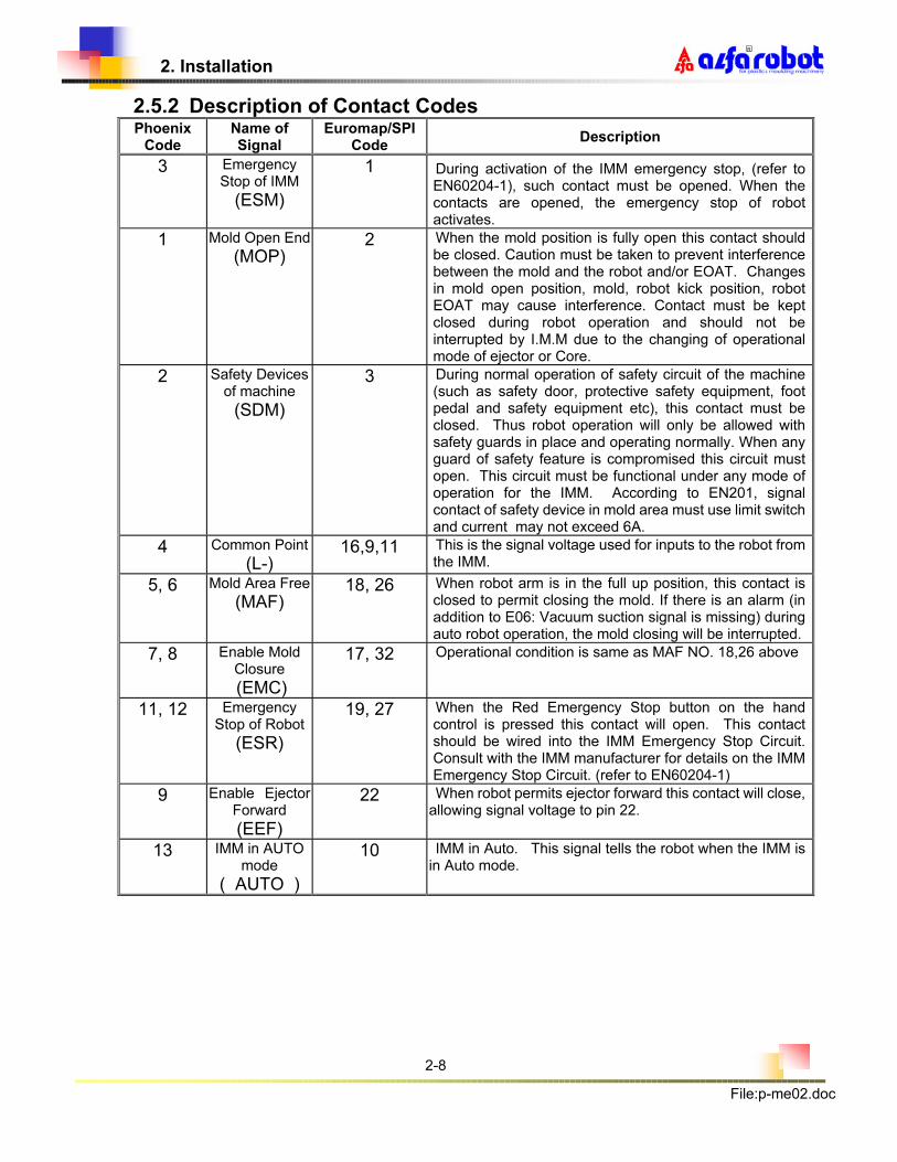
2.5.2 Description of Contact Codes Phoenix
Code Name of Signal
Euromap/SPI Code
Description
3 Emergency Stop of IMM
(ESM)
1 During activation of the IMM emergency stop, (refer to EN60204-1), such contact must be opened. When the contacts are opened, the emergency stop of robot activates.
1 Mold Open End
(MOP) 2 When the mold position is fully open this contact should
be closed. Caution must be taken to prevent interference between the mold and the robot and/or EOAT. Changes in mold open position, mold, robot kick position, robot EOAT may cause interference. Contact must be kept closed during robot operation and should not be interrupted by I.M.M due to the changing of operational mode of ejector or Core.
2 Safety Devices of machine
(SDM)
3 During normal operation of safety circuit of the machine (such as safety door, protective safety equipment, foot pedal and safety equipment etc), this contact must be closed. Thus robot operation will only be allowed with safety guards in place and operating normally. When any guard of safety feature is compromised this circuit must open. This circuit must be functional under any mode of operation for the IMM. According to EN201, signal contact of safety device in mold area must use limit switch and current may not exceed 6A.
4 Common Point
(L-) 16,9,11 This is the signal voltage used for inputs to the robot from
the IMM.
5, 6 Mold Area Free
(MAF) 18, 26 When robot arm is in the full up position, this contact is
closed to permit closing the mold. If there is an alarm (in addition to E06: Vacuum suction signal is missing) during auto robot operation, the mold closing will be interrupted.
7, 8 Enable Mold Closure
(EMC)
17, 32 Operational condition is same as MAF NO. 18,26 above
11, 12 Emergency Stop of Robot
(ESR)
19, 27 When the Red Emergency Stop button on the hand control is pressed this contact will open. This contact should be wired into the IMM Emergency Stop Circuit. Consult with the IMM manufacturer for details on the IMM Emergency Stop Circuit. (refer to EN60204-1)
9 Enable Ejector Forward
(EEF)
22 When robot permits ejector forward this contact will close, allowing signal voltage to pin 22.
13 IMM in AUTO mode
( AUTO )
10 IMM in Auto. This signal tells the robot when the IMM is in Auto mode.

2. Installation
File:p-me02.doc
2-9
�R
2.6 Connection with Pneumatic Supply Source
2.6.1 Pneumatic Supply
In order to maintain the robot's normal operation, be sure to use a refrigerated air dryer at the
outlet of the air compressor to remove the moisture from the air and thus to obtain an extended
service life for the robot.
AIR COMPRESSOR
Refrig
Dryer
Output
5kgf/cm2
Air Filter
2.6.2 Connection with Pneumatic Source of Supply
Important:
Tube Fitting
– Outlet
Tube Fitting– Inlet
Input Pressure 5kgf/cm²
Output Pressure 70 psi
Pressure
Gauge
Drain Button

2. Installation
File:p-me02.doc
2-10
�R
1. To minimize air pressure loss use rigid pipe for runs over 10 meters.
2. After completing the connection, adjust the pressure on the Air Filter/Regulator to 70 psi.
3. Check for water trapped in the Air Filter/Regulator and remove it everyday.
2.7 Safety and Function Test
After completion of installation of the robot on the injection molding machine in accord- ance
with the instructions stipulated in paragraph 2.2 to 2.5 of this chapter, the following areas must
be fully checked and tested. This will insure that the safety interlocks are functioning.
(1) “Mold Close Permit” signal,
(2) “Safety Gate Open” signal,
(3) “Mold Open End” signal,
(4) “Auto/Manual Mode of IMM” signal,
(5) “Emergency Stop” function on both the robot and IMM,
(6) “Adjustment of Moving Speed” for all axes,
(7) Detection of “Reset Function”,
(8) “Mold Close Function” after removal of moldings.
[Attention] Connection test must be carried out by a fully trained technician
or engineer only. If there is any problem, please feel free to contact
PPE.
2.8 Procedures for Robot Dismantlement
1. Turn OFF power to I.M.M and lockout.
2. Turn OFF power of the robot.
3. Disconnect the pneumatic source to the robot.
4. Exhaust air pressure from the robot. (disconnect air lines at wrist speed control 4.6.4)
5. Loosen mounting bracket for the kick cylinder and move arm to make it closer to traverse beam.
6. Move mounting bracket for shock absorber to make it closer to arm.

2. Installation
File:p-me02.doc
2-11
�R
7. Tighten mounting bracket for the kick cylinder and make arm unable to be moved.
8. Disconnect the hand-held control pendant.
9. Dismantle connection between the robot and I.M.M.
10. Disconnect electrical power cable to the robot.
11. Insert swing lock screw.
12. Loosen mounting screws and remove the robot from machine platen.

3. Description of Robot Structure
3-1
File:p-me03.doc
3. DESCRIPTION OF ROBOT STRUCTURE
3.1 Illustration
Phoenix350~450
Base C
om
part
ment
Contr
ol B
ox
Pneum
atic
Com
part
ment
Headw
ork
(E
OA
T)
(For
model denote
s “
V”
only
)
Hand-h
eld
Pendant
Arm
Com
part
ment
Kic
k B
eam
3. Description of Robot Structure
3-2
File:p-me03.doc
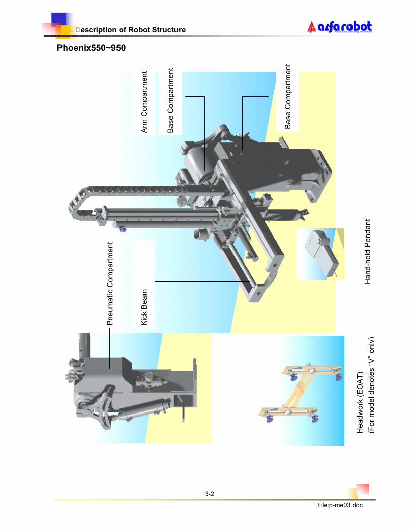
Phoenix550~950
Base C
om
part
ment
Kic
k B
eam
Pneum
atic C
om
part
ment
Headw
ork
(E
OA
T)
(For
model denote
s “
V”
only
) H
and-h
eld
Pendant
Arm
Com
part
ment
Base C
om
part
ment

3. Description of Robot Structure
3-3
File:p-me03.doc
3.2 Specifications
Single-Stage Telescopic Model
P350 P450 P550 P650 P650W P750W P850W P950W
Suitable IMM
Tonnage (ton) 15~30 30~60 50 ~ 150 75 ~ 200 75 ~ 200
100 ~
250
150 ~
300
200 ~
400
Vertical Stroke
(mm) 350 450 550 650 650 750 850 950
Kick
Stroke (mm) 75 120 200
SwingOut
Angle (degree) 60-90 60~90 60~90
Max..Kick
Position (mm) 230 420 430
Max. Payload
(Kg) 2.5 3 3
Minimum Take
Out Time (sec) 0.6 0.7 0.8 0.9 0.8 1 1.2 1.4
Minimum Dry
CycleTime
(sec)
3.8 4.0 4.2 4.4 4.2 4.8 5.2 6
Power
Consumption
(KVA)
0.5 0.5 0.5 0.5 0.5 0.5 0.5 0.5
Air
Consumption
(Nl/cycle)
1.5 1.5 1.6 1.7 2.2 2.5 2.8 3
Net Weight
(Kg� 30 31 35 36 42 43 44 45
Dimension
L x W x H (mm)
550*285
*1015
550*285
*1135
815*300
*1390
815*300
*1490
965*300
*1250
965*300
*1300
965*300
*1450
965*300
*1500
Remarks:
1. Runner/sprue gripper and wrist rotation mechanism is included as standard features.
2. Options: 1) Models fitted with vacuum generator and suction headwork (EOAT) are denoted by
‘V’. Note: These models require additional air consumption of 5Nl/cycle.
2) Platen spacer of 50, 100, 150 and 200mm height.

3. Description of Robot Structure
3-4
File:p-me03.doc
3.3 Dimensions
for plastics moulding machinery
R
R
for plastics moulding machinery
Mo
del P
350(V
) &
P450(V
) M
od
el P
650W
(V)
~ P
950W
(V)

3. Description of Robot Structure
3-5
File:p-me03.doc
3.3.3 Profiles
Single Stage Version
Telescopic Version

3. Description of Robot Structure
3-6
File:p-me03.doc
3.4 Exploded View
Base Compartment
Phoenix350~450
3.4.1.1 Part List for Base Compartment of Poenix350~450
ITEM DESCRIPTION PART NO. Q`TY REMARK
1 Base Block PC03A040 1
2 Location Ring PC03A070 1
3 Column PC03A090 1
4 Location Pin PI00A080 1
5 Arch PC03A010 1
6 Tube Fitting, quick release PET2001 1
7 Swing Axle PC03A030 1
8 Swing Angle Adjustment Knob PC03A060 1
9 Connector Block, swing cylinder MBG5-PHS12 1
10 Swing Cylinder YC320080 1
11 Swivel Shaft, swing cylinder PC03A050 1
12 swing cylinder Base PC03A020
13 Axle Bearing MBG1-6007 2
14 Location Screw PC03A080 1

3. Description of Robot Structure
3-7
File:p-me03.doc
Phoenix550~950

3. Description of Robot Structure
3-8
File:p-me03.doc
3.4.1.2 Part List for Base Compartment of P550-950
ITEM DESCRIPTION PART NO. Q`TY REMARK
1 Main Column PI00A010 1
2 P550/P650 Base Block PI00A020 1
3 Swivel Shaft, swing arm PI00A030 1
4 Swing Angle Adjustment Bracket PB00A041 1
5 Shaft for Main Column PB00A052 1
6 Swivel Shaft, swing cylinder PB00A061 1
7 Swing Angle Adjustment Knob PB00A082 1 M6*12screw
8 Locating Pin PB00A090 1
9 Connector Block, swing cylinder MBG5-PHS12 1
10 Clamping Wrench PI00A110 1
11 P550/P650 Swing Cylinder PCY40-YC400125 1
P650W~P950W Swing Cylinder PCY50-YC500120Y 1
12 Tube Fitting, speed control AS2201F-01-04 2
13 Air Filter/Regulator PET2001 1
14 Cable Holder, lower RXE1002 1
15 Cable Holder, upper RXE1001 1
16 Tube Fitting, quick release RFL0200 1
17 Tube Fitting, quick release KQL10-02S 1
18 Bearing MBG-6008ZZ 2
19 Lock Nut MSW8-AN08 1
20 Spring Washer MSW8-AW08 1
21 Magnetic Switch RSN2002 2
22 Lock Nut MSW8-AN00 1
23 Spring Washer MSW8-AW00 1
24 Bearing MBG-6800ZZ 2
25 Clamping Wrench Spring PI00A120 1
26 Shaft Distance Spacers PI00A100 1
27 Screw M10*40L MSW6-1040 1
28 Washers for linear shaft MSW8-1031 1
3. Description of Robot Structure
3-9
File:p-me03.doc
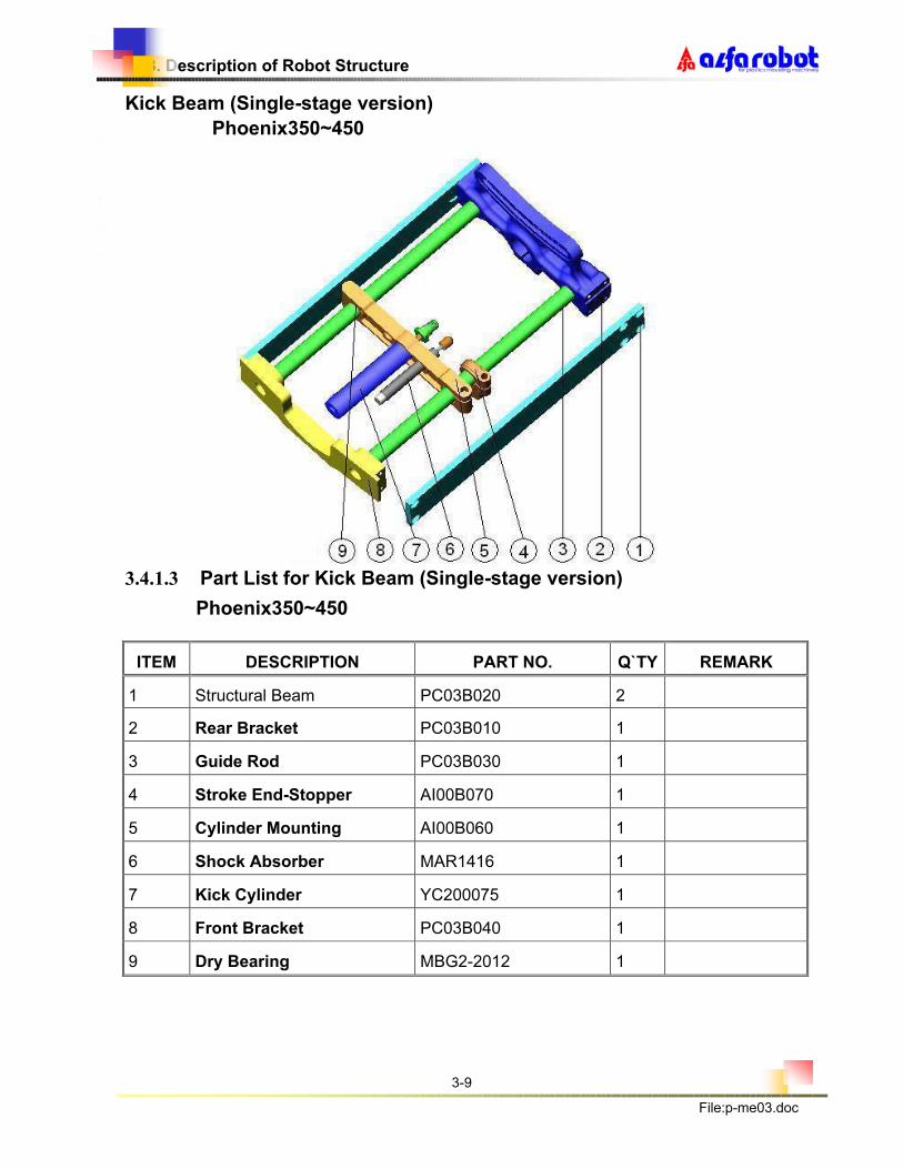
Kick Beam (Single-stage version)
Phoenix350~450
3.4.1.3 Part List for Kick Beam (Single-stage version)
Phoenix350~450
ITEM DESCRIPTION PART NO. Q`TY REMARK
1 Structural Beam PC03B020 2
2 Rear Bracket PC03B010 1
3 Guide Rod PC03B030 1
4 Stroke End-Stopper AI00B070 1
5 Cylinder Mounting AI00B060 1
6 Shock Absorber MAR1416 1
7 Kick Cylinder YC200075 1
8 Front Bracket PC03B040 1
9 Dry Bearing MBG2-2012 1

3. Description of Robot Structure
3-10
File:p-me03.doc
Phoenix550~950
3. Description of Robot Structure
3-11
File:p-me03.doc
3.4.1.4 Part List for Kick Beam (Single-stage version)
Phoenix550~950
ITEM DESCRIPTION PART NO. Q`TY REMARY
1 Rear Bracket PI00B010 1
2 structure beam MFA-PI00B020 2
3 Front Bracket AI00B010 1
4 Cylinder Mounting Bracket AI00B060 1
5 Stroke End-Stopper AI00B070 1
6 Guide Rod YE200500 2
7 Lifting Bolt MSW9-1001 1
8 Shock Absorber MAR1001 1
9 Kick Cylinder PCY20-YC200120K 1
10 Tube Fitting, speed control AS2201F-01-04 2
11 Dry Bearing MRG2-2012 1

3. Description of Robot Structure
3-12
File:p-me03.doc
Kick Beam (Telescopic version) Phoenix550W~950W
1
2
3
4
6
7
13
12
10
8
9
5
11
3. Description of Robot Structure
3-13
File:p-me03.doc
3.4.1.5 Part List for Kick Beam (Telescopic version)
ITEM DESCRIPTION PART NO. Q`TY REMARK
1 structure beam MFA-PI00B020 2
2 Guide Rod YE200500 2
3 Cylinder connector PT00B040 1
4 Axle Bearing MBG2-2012 1
5 Shock Absorber MAR2030-5k 1
6 Tube Fitting, speed AS2201F-01-04 2
7 Front Bracket AI00B050 1
8 Lifting Bolt MSW9-1001 1
9 Rear Bracket PI00B010 1
10 Stroke End-Stopper AI00B070 1
11 Kick Cylinder Link AI00C070 1
12 Cylinder Mounting PT00B010 1
13 Kick Cylinder PCY25-YC250200 1

3. Description of Robot Structure
3-14
File:p-me03.doc
Arm Compartment (Single-stage version)
1
2
3
4
6
7
5
8
9
10
11
12
13
14 24
23
22
21
20
19
18
17
16
15
25

3. Description of Robot Structure
3-15
File:p-me03.doc
3.4.1.6 Part List for Arm Compartment (Single-stage version)
ITEM DESCRIPTION PART NO. Q`TY REMARK
1 Upper Protective Plate AI00C120 1
2 Tube Fitting, speed control AS2201F-01-08 2
Vertical Cylinder PCY25-YC250350K 1 P350
Vertical Cylinder PCY25-YC250450K 1 P450
Vertical Cylinder PCY25-YC250550K 1 P550 3
Vertical Cylinder PCY25-YC250650K 1 P650
4 Stroke stopper Block AI00C090 1
5 Stroke End-stopper AI00C080 1
6 Cable Holder MCN2011 1
Cable Holder Bracket,lower PB03B070 1 P350,P450 7
Cable Holder Bracket,lower PB00B070 1 P550,P650
8 Linear Bearing MBG4-JB20 4
Slide Rail MLA15-520 1 P350
Slide Rail MLA15-640 1 P450
Slide Rail MLA15-760 1 P550 9
Slide Rail MLA15-880 1 P650
10 Sliding Block MLA15B2 2
11 Main Bracket PB00C011 1
12 Kick Cylinder Linker AI00C070 1
13 Shock Absorber MAR2030-4-5K 1
14 Cylinder Holder, safety lock AI00C040 1
Cable Protective Chain MCN3010 1 P350
Cable Protective Chain MCN3010 1 P450
Cable Protective Chain MCN3010 1 P550 15
Cable Protective Chain MCN3010 1 P650
structure beam MFA-PC03C020 1 P350
structure beam MFA-PC04C020 1 P450 16
structure beam MFA-PI05C020 1 P550

3. Description of Robot Structure
3-16
File:p-me03.doc
structure beam MFA-PI06C020 1 P650
17 Terminal Cover AI00B050 1
18 Lower Protective Plate AI00B030 1
19 Vertical Cushion Cylinder PCY20-YC200081 1
20 Tube Fitting, speed control AS2201F-01-04 2
21 Main Cylinder Holder AI00C030 1
22 Sensor RSN1001 1
23 Sensor Seat AI00C120 1
24 Lower Mounting Plate AI00D050 1
25 Safety Lock Cylinder PCY2015 1

3. Description of Robot Structure
3-17
File:p-me03.doc
Arm Compartment (Telescopic version)
1
2
3
4
5
6
7
8
9
10
11
12
13
14
15
16
17
29
19
18
20
21
22
26
27
28
30
32
31
33
34
24
23
25

3. Description of Robot Structure
3-18
File:p-me03.doc
3.4.1.7 Part List for Arm Compartment (Telescopic)
ITEM DESCRIPTION PART NO. Q`TY REMARK
1 Upper Mounting Plate AW00C050 1
MCN3010 18 A550W
MCN3010 20 A650W
MCN3010 22 A750W
2 Cable Protective Chain
MCN3010 24 A850W
3 Upper Protective Plate AI00C110 1
AW05C030 1 A550W
AW06C030 1 A650W
AW07C030 1 A750W
4 structure beam II
AW08C030 1 A850W
5 Belt Clamping Plate AW00C180 1
6 Belt Clamp AW00C190 2
MLA15-520 2 A550W
MLA15-580 2 A650W
MLA15-640 2 A750W
7 Slide Rail
MLA15-720 2 A850W
8 Lower Protective Plate AW00B070 2
9 Sliding Block MLA15B 4
10 Lower Mounting Plate AW00C040 1
11 Swing Cylinder Mounting PT00C010 1
AW05C020 1 A550W
AW06C020 1 A650W
AW07C020 1 A750W
12 structure beam I
AW08C020 1 A850W
13 Linear bearing MBG4-JB20 4
14 Main Bracket AW00C010 1

3. Description of Robot Structure
3-19
File:p-me03.doc
Item Description Part No. Q’TY Remark
15 Cylinder Bracket , safety AW00C150 1
16 Sensor RSN1004 1
17 Safety Lock Cylinder PCY2005 1
AW05C040 1 A550W
AW06C040 1 A650W
AW07C040 1 A750W
18 Profile Cover
AW08C040 1 A850W
MBT1-8M20 1.1m A550W
MBT1-8M20 1.2m A650W
MBT1-8M20 1.3m A750W
19 Belt
MBT1-8M20 1.4m A850W
20 Tube Fitting Speed AS2201F-01-08 2
21 Stroke stopper Block AI00C090 1
22 Stroke End-stopper AI00C100 1
23 Absorber Base PT00B030 1
24 Cable Holder MCN2004 1
25 Washer AW00C080 1
26 Main Cylinder Holder AW00C060 1
27 Sensor Seat AI00C160 1
28 Shock Absorber MAR2030-4-5K 3
29 Washer AW00C070 1
30 Belt Wheel Top Mount AW00C120 2
31 Belt Wheel Locking Pin AW00C130 2
32 pulley MBTI-YF081501 2
33 Axle Bearing MBG1-6002 4
34 Belt Wheel Side Mount BW00C080 4

3. Description of Robot Structure
3-20
File:p-me03.doc
Gripper Compartment
Complete Wrist Assembly
JR01R010
Complete Gripper Assembly
TOP10620
Air Detecting Compartment
JR08R010

3. Description of Robot Structure
3-21
File:p-me03.doc
3.4.1.8 Part List for Gripper Compartment
ITEM DESCRIPTION PART NO. Q`TY REMARK
- Complete Wrist Assembly JR01R010 -
1 Main Wrist Bracket Not Available 1
2 Side Cover Not Available 2
3 Piston Rack Not Available 1
4 Rack Not Available 1
5 Piston Not Available 1
6 Gear Not Available 1
7 Ball Bearing Not Available 2
8 Snap Ring Not Available 1
9 Packing Not Available 2
10 Tube Fitting , quick release KQL04-M5 2
11 Screw Not Available 2
12 Tube Fitting TOPM5B4 2
13 Gripper Mounting Plate 1 CHKA0900 1
14 Gripper Mounting Plate 2 CHKA0800 1
- Complete Gripper Assembly TOP10620 - Excl. 24
15 Gripper Cylinder Not Available 1
16 Gripper Mounting Block 2 Not Available 1
17 Gripper Side Plate Not Available 1
18 Gripper Side Plate Not Available 1
19 Gripper Mounting Block 1 Not Available 1
20 Gripper Link 2 Not Available 2
21 Gripper Link 1 Not Available 2
22 Rivet 2 (10mmL) Not Available 1
23 Rivet 1 (26mmL) Not Available 2
24 Tube Fitting TOPM5B4 2
- Air Detecting Compartment JR08R010 -
25 Air Detecting Not Available 1
26 Switch RSN3008 1
27 Air Mounting Not Available 1

3. Description of Robot Structure
3-22
File:p-me03.doc
Pneumatic Compartment

3. Description of Robot Structure
3-23
File:p-me03.doc
3.4.1.9 Part List for Pneumatic Compartment
ITEM DESCRIPTION PART NO. Q`TY REMARK
1 Front Cover PI00H010 1
2 Mounting Plate PI00H020 1
3 Solenoid Valve Asy PSV-IN4S+1D 1 RCD2413 Double Sol
RCS2413 Single Sol
4 Tube Fitting, quick release KQL08-01S 2
5 Tube Fitting, quick release KQL04-01S 2
6 Tube Fitting, speed control AS2201F-01-04 2
7 Copper Elbow PFL0101 1
8 Tube Fitting, quick release KQU04-02S 1
9 Tube Fitting, quick release PQE0401 2
10 Copper Elbow PFL0202 1
11 Nipple PTA0101 1
12 Nipple PTA0202 1
13 Cable Holder MCN2011 1
14 Check Valve PTE0202 1
15 Silencer PET3001 2
16 Vacuum Generator PET1008 1 For model denotes
by ‘V’ only
17 Tube Fitting, quick release KQL10-02S 1
18 Air Detecting JR08R010 1

3. Description of Robot Structure
3-24
File:p-me03.doc
Control Compartment

3. Description of Robot Structure
3-25
File:p-me03.doc
3.4.1.10 Part List for Control Compartment
ITEM DESCRIPTION PART NO. Q`TY REMARK
1 Power Supply Base PI00H040 1
2 Control Box PI00H030 1
3 Power Supply RPW2008 1
4 Rocker Switch RBT1003 1
5 Warning Light RLT1003 1
6 Relay Board RBD-GA28-PC2 1
7 Cooling Fan REL2008 1
8 Alarm Buzzer REL1004 1
9 Power Filter RPW2005 1

3. Description of Robot Structure
3-26
File:p-me03.doc
Hand-held Pendant

3. Description of Robot Structure
3-27
File:p-me03.doc
3.4.1.11 Part List for Hand-held Pendant (RBD1019)
ITEM DESCRIPTION PART NO. Q`TY REMARK
1 Panel Case (Upper) GA28E010 1
2 Panel Case (Lower) 1
3 Main Control Board RBD-GA28-PC3A 1
4 Panel Screen (LCD) RBD-GA28-PC4 1
5 Emergency Stop Button RSN4004 1
6 Hand-held Keyboard RBD-GA28-PC1 1
7 Film of Keyboard RBT2-GA28E051 1
8 Keyboard Cable RCB1001 1
9 LCD Cover GA28E030 1

3. Description of Robot Structure
3-28
File:p-me03.doc
Standard Headwork (End-Of-Arm-Tooling)

3. Description of Robot Structure
3-29
File:p-me03.doc
3.4.1.12 Part List for Standard Headwork (complete Assembly : JA05-
200A1)
ITEM DESCRIPTION PART NO. Q`TY REMARK
1 Spring plunger TOP31060T 4
2 Suction Pad TOP33010 4 Changeable
3 Screw TOP24408 2
4 Mount Board TOP30620 1
5 Mount Board TOP30200 2
6 Lock Nut Included w/ TOP24408 2
Remark: This headwork assembly is supplied for model denotes by ‘V’
only.

4. Setting and Adjustment before Operating
4-1
File:p-me04.doc
�R
4. SETTING AND ADJUSTMENT BEFORE OPERATING
4.1 Connection with Injection Moulding Machine
Before putting robot into operation, it must be linked with I.M.M. by connecting the
Euromap/PSI-standard Interface Connector.
IMPORTANT: When robot is NOT IN USE, power switch MUST be turned OFF.

4. Setting and Adjustment before Operating
4-2
File:p-me04.doc
�R
4.2 Pneumatic Supply
IMPORTANT:
(1) After connecting with the pneumatic supply source, adjust working pressure to
5kgf/cm2 by adjusting the pressure regulator.
(2) Pay attention to check water level in reservoir daily and drain water as required to
avoid overflow.
(3) To carry out pressure adjustment pull out the knob slightly, turn clockwise for higher
pressure or turn counter-clockwise for lower pressure.
Tube Fitting
– Outlet
Water
drain
Inlet
Input Pressure 70 PSI
Output Pressure 5kgf/cm²
Pressure
Gauge

4. Setting and Adjustment before Operating
4-3
File:p-me04.doc
�R
4.3 Turning ON Electrical Power Source
PROCEDURES:
(1) Double check to make sure that safety interlocks between Robot and I.M.M. are properly
connected, and then turns power switch ON.
� NOTE�PLEASE MAKE SURE THE CABLE FROM THE HAND-HELD
PENDANT TO THE CONTROL BOX IS FIRMLY ATTACHED BEFORE
TURNING “ON” POWER SWITCH.
(2) After turning ON power switch, screen on the hand-held pendant will display:
(3) If there is no display on the screen after turning ON power, it is may be a blown control fuse.
Please check the fuses and replaces it if necessary.
Alarm Buzzer
Fan
Power Switch
Warning Lamp
A L F A R O B O T
P h o e n i x S e r i e s
G A 2 8 C o n t r o l

4. Setting and Adjustment before Operating
4-4
File:p-me04.doc
�R
4.4 Adjustment for Mold Change
SAFETY ITEMS MUST BE
FULLY OBSERVED
AFTER COMPLETION OF A MOLD CHANGE YOU MAY
WISH TO ADJUST THE ROBOT, THE FOLLOWING
SAFETY RULES MUST BE FULLY OBSERVED.
(1) Do not adjust the robot unless you are a fully trained person.
(2) Switch the I.M.M. to Manual mode and move the platen to full open position,
and then turn power of the I.M.M. to OFF.
(3) Turn power OFF to the robot and disconnect pneumatic supply source to the
robot.
Important: Unless above actions are complete, do not adjust the robot.
4.4.1 Adjustment of Kick Stroke
Kick Cylinder Safety Lock Cylinder
Kick Stroke
End Stopper
Kick Cylinder
Mounting
Plate
Lock Screw
Lock Screw

4. Setting and Adjustment before Operating
4-5
File:p-me04.doc
�R
PROCEDURES:
(1) Loosen lock screws on both the kick cylinder mounting plate and kick stroke end
stop.
(2) Moves arm horizontally to a safe position between mold halves, and pull out
safety lock cylinder and allow the arm to descend between the mold halves.
(3) Push arm forward to the correct position for product/ sprue removal, be careful
not to damage mold. Lock tightly lock screw on the kick cylinder mounting plate.
Be sure to allow for ejector motion and other factors for consistant take out.
(4) Pushes arm toward the injection nozzle to a position that is clear for removal and
does not interfere with mold. Lock kick stroke end stop in place. Test by
pushing against stop. (shock absorber should be fully compressed)
4.4.2 Adjustment of Vertical Strokes
Single Stage Arm Telescopic Type Arm
PROCEDURES:
(1) Loosen set screws on the vertical stroke end stop.
(2) Move the vertical stroke stop to the proper position to allow the robot to grip
sprue/runner or to remove the molded part(s).
(3) Lock tightly set screws, and then move the arm up and return the safety lock
cylinder to the locked position.
Vertical Stroke Stopper Vertical Stroke Stopper

4. Setting and Adjustment before Operating
4-6
File:p-me04.doc
�R
4.4.3 Adjustment of Swing Angle
P350~P450
PROCEDURES:
1.Loosen locking nut for the swing angle adjustment.
2.Swing arm manually to the desired swing direction (operator side, or
non-operator side) and angle, and also adjust locking nut for the swing
angle adjustment. 3.Pull out the safety lock cylinder, and then pull arm down to the fully
extended position to see if there is any interference; if not, tighten locking
nut of the swing angle adjustment.
Locking Nut for Swing
Angle Adjustment
Left turn 50 ~90° Right turn 50 ~ 90°
Swing-Out Confirmation
Switch
Swing-In Confirmation
Switch

4. Setting and Adjustment before Operating
4-7
File:p-me04.doc
�R
P550~P950
PROCEDURES:
(1) Loosen locking nut for the swing angle adjustment.
(2) Swing arm manually to the desired swing direction (operator side, or non-operator
side) and angle, and also adjust locking nut for the swing angle adjustment.
(3) Pull out the safety lock cylinder, and then pull arm down to the fully extended
position to see if there is any interference; if not, tighten locking nut of the swing
angle adjustment.
Locking Nut for Swing
Angle Adjustment Right turn
50 ~ 90°
Left turn
50 ~90°
Swing-Out Confirmation
Switch
Swing-In Confirmation
Switch

4. Setting and Adjustment before Operating
4-8
File:p-me04.doc
�R
Arm Pivoting for Mold Change
P350~P450
PROCEDURES:
1.Loosen the screw on location ring
2.Pull Location Pin and swing round the arm, then change the Mold.
3.Reset the arm and location pin.
4.Tighten the screw.
5. Adjust strokes according to procedures as stipulated in above paragraphs
4.4.1, 4.4.2 and 4.4.3.
Screw
Location Pin
Location Ring

4. Setting and Adjustment before Operating
4-9
File:p-me04.doc
�R
P550~P950
PROCEDURES:
(1) Position the clamping wrench to allow for loosening the clamp pivot.
(2) Loosen the pivot clamp and lift up the licking pin from the base so that the arm
can be pivoted out to facilitate mold change..
(3) After completion of mold change pivot the arm back into position and push the
locking pin into the base.
(4) Turn the clamping wrench to tighten the pivot clamp.
(5) Adjust strokes according to procedures as stipulated in above paragraphs 4.4.1,
4.4.2 and 4.4.3.
NOTE: DURING MOLD CHANGING, PLEASE BE CAREFUL
NOT TO COLLIDE WITH THE ROBOT.
Tighten
Loosen
Clamping Wrench
Loosen
Tighten

4. Setting and Adjustment before Operating
4-10
File:p-me04.doc
�R
4.5 Installation and Adjustment of Headwork (EOAT)
PROCEDURES:
(1) Standard headwork (EOAT) shall be assembled as per the above diagram and
then installed on the gripper assembly.
(2) Use the "RED" tubing to supply Vacuum to the EOAT.
Headwork (EOAT)
Wrist Rotation
Cylinder
(JR01R010)
Gripper Assembly
(JC20R020)
Tube Fittings
Suction Cups

4. Setting and Adjustment before Operating
4-11
File:p-me04.doc
�R
4.6 Adjustment of Moving Speeds
4.6.1 Speed Adjustment for Kick Forward and Back
PROCEDURES:
(1) Turns the kick forward speed control valve for the adjustment of kick forward
moving speed.
(2) Turns the kick back speed control valve for the adjustment of kick back moving
speed.
(3) Turns clockwise for reducing speed, and turns counter-clockwise for increasing
speed.
(4) After proper adjustment is made, lock with locking nuts.
Kick Forward Speed
Control Valve
Kick Back Speed
Control Valve

4. Setting and Adjustment before Operating
4-12
File:p-me04.doc
�R
4.6.2 Speed and Cushion Adjustment for Arm Down
PROCEDURES:
(1) Turn the arm down speed control valve for the adjustment of arm down speed.
(2) Before moving arm down make sure that the arm up sensor is activated. Adjust
distance between the arm up sensor and the sensing piece to make it ON.
(3) Turns the cushion control valve for the adjustment of arm down cushion control.
(4) Turns clockwise for reducing speed, and turn counter-clock-wise for increasing
speed.
(5) After proper adjustment is made, lock with the locking nuts.
Arm Up Sensor
Arm Down Speed
Control Valve
Cushion Control
Valve

4. Setting and Adjustment before Operating
4-13
File:p-me04.doc
�R
4.6.3 Speed & Cushion Adjustment for Swing-in and Swing-out
PROCEDURES:
(1) Turn the swing-out speed control valve for the adjustment of swing-out speed.
(2) Turn the swing-out cushion control valve for the swing-out cushion control.
(3) Turn the swing-in speed control valve for the adjustment of swing-in speed.
(4) Turn the swing-in cushion control valve for the swing-in cushion control.
(5) Turn clockwise for reducing speed, and turn counter-clockwise for increasing
speed.
(6) After proper adjustment is made, lock with the locking nuts.
Swing-out Cushion
Control Valve
Swing-out Speed
Control Valve
Swing-in Cushion
Control Valve
Swing-in Speed
Control Valve

4. Setting and Adjustment before Operating
4-14
File:p-me04.doc
�R
4.6.4 Speed Adjustment for Wrist Rotation
PROCEDURES:
(1) Turn the wrist rotation speed control valve for the adjustment of wrist rotation
speed.
(2) Turn the wrist rotation-back speed control valve for the adjustment of wrist
rotation-back speed.
(3) Turns clockwise for reducing speed, turn counter-clockwise for increasing
speed.
(4) After proper adjustment is made, lock with the locking nuts.
Wrist Rotation-back
Speed Controller Valve Wrist Rotation
Speed Control Valve

5. Maintenance
5-1
File:p-me05.doc
�R
5. MAINTENANCE 5.1 Maintenance and Repair Safety
�NOTE�MAINTENANCE PERSONNEL, PLEASE READ THE FOLLOWING SAFETY
REQUIREMENTS BEFORE PERFORMING ANY MAINTENANCE.
1. Turn the power switch of the ROBOT to OFF and lock the switch before
performing maintenance to the I.M.M.
2. Disconnect pneumatic supply source, and Bleed Out residual compressed air
inside the pneumatic circuits of the ROBOT before performing maintenance to
the ROBOT. Bleed system by removing air lines at wrist speed control valves.
(see 4.6.4 for picture)
3. Proximity switches, sensors, and faulty solenoid valves can be repaired by the
user, other items should only be repaired by a fully trained technician.
4. Do not make any changes or modifications to the ROBOT.
5. During adjustment of the ROBOT or mold change, be careful to avoid injury.
6. After completion of adjustment or maintenance of the ROBOT, please clear
danger zones before re-starting.
7. During maintenance, do not turn ON the power supply source, or re-connect
pneumatic supply source to the ROBOT.
8. Make sure all safety guards are in place prior to restarting ROBOT.
5. Maintenance
5-2
File:p-me05.doc
�R
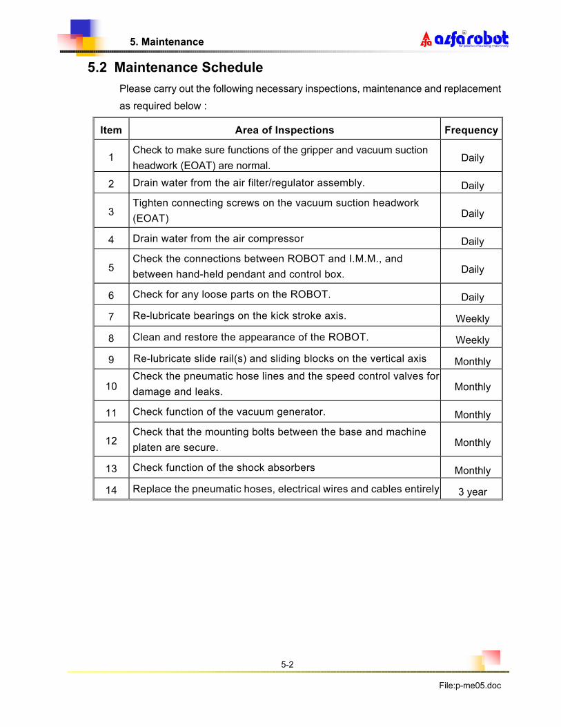
5.2 Maintenance Schedule
Please carry out the following necessary inspections, maintenance and replacement
as required below :
Item Area of Inspections Frequency
1 Check to make sure functions of the gripper and vacuum suction
headwork (EOAT) are normal. Daily
2 Drain water from the air filter/regulator assembly. Daily
3 Tighten connecting screws on the vacuum suction headwork
(EOAT) Daily
4 Drain water from the air compressor Daily
5 Check the connections between ROBOT and I.M.M., and
between hand-held pendant and control box. Daily
6 Check for any loose parts on the ROBOT. Daily
7 Re-lubricate bearings on the kick stroke axis. Weekly
8 Clean and restore the appearance of the ROBOT. Weekly
9 Re-lubricate slide rail(s) and sliding blocks on the vertical axis Monthly
10 Check the pneumatic hose lines and the speed control valves for
damage and leaks. Monthly
11 Check function of the vacuum generator. Monthly
12 Check that the mounting bolts between the base and machine
platen are secure. Monthly
13 Check function of the shock absorbers Monthly
14 Replace the pneumatic hoses, electrical wires and cables entirely 3 year

5. Maintenance
5-3
File:p-me05.doc
5.3 Basic Maintenance Tools
1. Allen Wrenchs 2.5 to 8mm
2. Adjustable Wrench 8 to14mm
3. Screwdrivers
4. Pliers
5. Multi-Meter
6. Air Gun
7. Grease Gun
5.4 Lubrication
5.4.1 Regular lubrication of the linear slide rails, linear bearings, and roller bearings is absolutely necessary.
5.4.2 Frequency of Lubrication: Re-lubrication should be made about every 50,000 cycles or every month.
5.4.3 Type of Grease: Yellow grease or soap lubricant oil No. 2 series:
1/ ISEVG32-68……….. Transparent smooth lubricating oil.
2/ ALVANIA GREASE NO.2 (SHELL Brand).
3/ ALVANIA EP\2 (SHELL Brand).
5.4.4 Location of Lubrication:
1/ Vertical slide rails and sliding blocks.
2/ Crosswise guide rod and linear bearings.
5.4.5 Method of Lubrication�
(1)Sliding blocks�Squeeze grease into the sliding blocks for lubrication.
(2) Slide Rails and Bearings�Apply grease on the surfaces by brushing.
5.4.6 Lubrication-free air cylinders are utilized on this ROBOT, therefore no lubrication is necessary for the air cylinders.

5. Maintenance
5-4
File:p-me05.doc
5.5 Pneumatic Circuit Diagram

5. Maintenance
5-5
File:p-me05.doc
5.5.1 Pneumatic Part List
NO. DESCRIPTION PART NO. Q’TY REMARK
1 Quick Coupler PFL0200 1
2 Filter/ Regulator PET1020 1
3 Instant Fitting KQL10-02S 1
4 Instant Fitting KQH10-02S 1
5 Check Valve PET0202 1
6 Insert Core PTF0002 5
7 Nipple PTA0202 1
8 Muffler/Silencer PET2024 2
9 Instant Fitting KQU04-02S 1
11 Solenoid Valve PSV1-N54S+1D 1SET
13 Instant Fitting KQL04-01S 2
14 Instant Fitting KQH04-01S 2
15 Instant Fitting KQH04-01S 2
16 Instant Fitting KQL10-01S 2
17 Brass Elbow PFL0101 1
18 Screw Plug MSW3-PT(1/8) 1
19 Nipple PTA0101 1
20 Vacuum Generator PET1008 1
21 Brass Elbow PFL0601 1
22 Speed Control Valve AS2201F-01-04 6
23 Brass Elbow PQE0401 2
24 Speed Control Valve AS2201F-01-04 2
25 Speed Control Valve AS2201F-01-08 2
26 Brass Elbow PTB0101 2

6. Electrical System
6-1
File: p-me06.doc
6. ELECTRICAL SYSTEM
6.1 Power System Circuit Diagram
PE:Green
PE
L:blackN:Blue
LOAD
NOISE
EMI
K4A
K4
S2
POWER
SUPPLY
S1
LINE
Fuse 2A
GA28-PC2
CN4
GA28-PC2
CN5
V1
L+
PE L2
TNR
NC R1
R1
N
2b 2a 1b 1a
2 1
L
S1
R2
AC1
R1
Power switch
DC24V
G1
L-
AC2

6. Electrical System
6-2
File: p-me06.doc
6.2 Safety Ground Circuit Diagram
CABLE 2
GA28-PC2
CN4
PE E
PE:Green
Hand-held Pendant
2
0.75mm
Power Supply
EMI Noise
Control Box
2
0.75mm
2
0.75mm
E E E
2
0.75mm
Connect Board
GA28-PC2

6. Electrical System
6-3
File: p-me06.doc
6.3 Emergency Stop Circuit Diagram
( RB
D- G
A28-P
C3)
( RB
D-G
A28-P
C2)
RO
BO
T E
-St o
p
X9
JU
MP
3
Y9
21 3
CP
UJU
MP
1
JU
MP
2
JU
MP
4
L+
CN1/1
CN1/2
2
CN
4/1
1
CN
4/2
2
1 43 321 5
CN
4/2
5
2 31
K3
1
JU
MP
1
JU
MP
2
CN
1/1
1
CN
1/2
2
3
2
1 3
2
1
CN
1/ 2
5
K3
1
K3
K3
1
RO
BO
T E
- ST
OP
CN
6/ 3
CN
3/7
L-
CN
6/ 4
L-
Main
Cont r
olle
r B
oard
R
el a
y B
oar d

6. Electrical System
6-4
File: p-me06.doc
6.4 Input / Output Diagram
X3
Warning
BUZZER
Y7
Y8
Y6
K5
LIGHT
Output
Emergency
Y2
Y5
Y4
Y3
Y1
K6
X6
X9
X8
X7
X4
K7
Arm up Sensor
Input
X2
X1
L+ L-
K3
K1Y10
Y11 K2
Y9
Swing InwardSensor
Swing OutwardSensor
GripConfirmation
Vacuum SuctionConfirmation
Safety DevicesOf Machine
Mould OpenEnd
Arm UP/Down
Forward/Backward
Swing Inward
Swing Outward
Gripper
Vacuum Suction
Conveyor / or Spray
Emergency Stop
Mould Area
Enable Ejector
Free
Forward
Auto/Manualof IMM
Stop of IMM
of Robot

6. Electrical System
6-5
File: p-me06.doc
6.5 RBD-GA28-PC2 Connection Diagram
CN4:Connect To Power And Earthing
Fuse 2A
SW1
CN6/5
CN6/6
TNR
Power SupplyCN5:Connect To
Power FilterS1N:Blue Cable(2)
L2
Power Safety Point(2,2b)
PE:Green Cable(2)
Power Switch
E
R1
4
5
PE
E
E
E
Power Supply
L+
L-
L-
L+
L-
L+
CN1:Connect To Controllor
12
19Y6
Y10
L-
Y11
Y9
Y7
Y8
23
24
25
22
20
21
Y2
Y5
Y3
Y4
L-
Y1
15
18
16
17
14
13
4X2
X6
X9
X7
X8
X5
X3
X4
8
11
9
10
7
5
6
L+
X1 3
1
2
Auto/Manual
CONV. Or
CN3:Other Connect
CN5/L-
J1/Y1,K6
CN2/AL
CN3/Y9,K3
K5
K2
CN5/L-
K1
J3/Y3
J6/Y6
J4/Y4
J5/Y5
J2/Y2
Spary
of IMM
CN5/L+
CN6/X7
CN6/X8
J9/X4,K7
CN3/X2
J11/X6
CN6/3
J10/X5
J8/X3
J7/X1
L-
Y9
K5
K5
L+
L+
X2
CN1/22
K5
L+
CN1/4
L+
L-
Warning LightCN2:Buzzer And
BZ
L+
SW2
SW2
AL
L+
L+
CN1/21
L+

6. Electrical System
6-6
File: p-me06.doc
6.6 I.M.M. Connection Diagram
X8 X7 X9 L-M
ou
ld O
pe
n E
nd
Mach
ine
(S
DM
)
Sa
fety
De
vic
es o
f
(MO
P)
1 2
1 2
En
ab
le M
ou
ld
Em
erg
en
cy S
top
Fre
e (
MA
F)
Mou
ld M
ou
ld
Fo
rwa
rd( E
EF
)E
na
ble
Eje
cto
r
Em
erg
en
cy S
top
83 4 5 6 7
K4
53 4
K6
K1
SW1
CN4/4CN4/5
6 7
K4
K7
K1
9 10 1211
98 10
K4A
K2
K4A
11 12
K3
CN1/11CN1/10 CN1/9 CN1/4
X2
Au
to/M
an
ua
l
13
13
of
IM
M (
ES
M)
of
IMM
(AU
TO
)
Clo
su
re(E
MC
)
of R
ob
ot(
ES
R)

6. Electrical System
6-7
File: p-me06.doc
6.7 Cable Code and Definition 6.7.1 IMM Connection Cable
Cable Code Definition Remarks
1 Mold Open End�MOP�
2 Safety Device of Machine�SDM�
3 Emergency Stop of I.M.M.�ESM�
4 Common Point (L–)
5 Mold Area Free�MAF�
6 Mold Area Free�MAF�
7 Enable Mold Closure�EMC�
8 Enable Mold Closure�EMC�
9 Enable Ejector Forward�EEF�
10 Enable Ejector Forward�EEF�
11 Emergency Stop of Robot�ESR�
12 Emergency Stop of Robot�ESR�
13 Auto/Manual of I.M.M.�AUTO�
14
15
16
6.7.2 Power Cable
Cable Code Definition Remarks
Black L Power Supply
(AC80~170V or AC170~260V Single-phase)
Dual Voltage
Switchable
Blue N Neutral
Green PE Ground / Earth

6. Electrical System
6-8
File: p-me06.doc
6.7.3 IMM Connection Cable (Euromap/SPI standards)
Euromap/SPI
Code
Cable code Connection Illustration
2 1 Mold Open End�MOP�
4
5
6
7
8
10 13 Auto/Manual of I.M.M.�AUTO�
12
15
16 4 Common Point (L–)
3 2 Safety Device of Machine�SDM�
11 4 Common Point (L–)
1 3 Emergency Stop of I.M.M.�ESM�
9 4 Common Point (L–)
17 7 Enable Mold Closure�EMC�
20
21 10, 8
22 9 Enable Ejector Forward (EEF)
23 10, 8
24 10, 8
28 10, 8
32 10, 8 Common Point
26 5 Mold Area Free �MAF�
18 6 Mold Area Free �MAF�
19 11 Emergency Stop of Robot �ESR�
27 12 Emergency Stop of Robot �ESR�

6. Electrical System
6-9
File: p-me06.doc
6.8 Main Control Board (RBD-GA28-PC3)

6. Electrical System
6-10
File:p-me06.doc
6.9 Hand-held Board (RBD-GA28-PC1)

6. Electrical System
6-11
File:p-me06.doc
6.10 Relay Board (RBD-GA28-PC2)

6. Electrical System
6-12
File:p-me06.doc
6.11 PC2 & PC3 Board Jumpers
(RB
D-G
A28
-PC
3)
(RB
D-G
A2
8-P
C2)
RO
BO
T E
-St o
p
X9
JU
MP
3
Y9
21 3
CP
UJU
MP
1
JU
MP
2
JU
MP
4
L+
CN1/1
CN1/2
2
CN
4/1
1
CN
4/2
2
1 43 321 5
CN
4/2
5
2 31
K3
1
JU
MP
1
JU
MP
2
CN
1/1
1
CN
1/ 2
2
3
2
1 3
2
1
CN
1/2
5
K31
K3
K3
1
RO
BO
T E
- ST
OP
CN
6/3
CN
3/ 7
L-
CN
6/4
L-
Main
Co
ntr
olle
r B
oar d
R
el a
y B
oard

7. Standard Pre-set Programs
7-1
File:p-me07.doc
○R
7. STANDARD PRE-SET PROGRAMS
Prog. No. 01 L Type motion, gripping work-piece from moving half:
� Motion sequence
1. Vertical Down 6. Swing Out
2. Kick 7. Vertical Down
3. Grip(Vacuum) 8. Release Work-piece
4. Kick Back 9. Vertical Up
5. Vertical Up 10. Swing In
Prog. No. 02 L Type motion, gripping work-piece from stationary half:
� Motion sequence
1. Vertical Down 6. Swing Out
2. Kick Back 7. Vertical Down
3. Grip(Vacuum) 8. Release Work-piece
4. Kick 9. Vertical Up
5. Vertical Up 10. Swing In
Prog. No. 03 U Type motion Gripping work-piece from moving half:
� Motion sequence
1. Vertical Down 6. Swing Out
2. Grip(Vacuum) 7. Vertical Down
3. Kick Back 8. Release Work-piece
4. Vertical Up 9. Vertical Up
5. Kick 10. Swing In
Prog. No. 04 U Type motion, gripping work-piece from stationary half:
� Motion sequence
1. Vertical Down 6. Vertical Down
2. Grip(Vacuum) 7. Release Work-piece
3. Kick 8. Vertical Up
4. Vertical Up 9. Swing In
5. Swing Out 10. Kick Back

7. Standard Pre-set Programs
7-2
File:p-me07.doc
○R
Prog. No. 05 L Type motion, gripping work-piece & sprue from moving half:
� Motion sequence
1. Vertical Down 7. Vertical Down
2. Kick 8. Release Work-piece
(Vacuum)
3. Grip & Vacuum 9. Vertical Up
4. Kick Back 10. Vertical Down
5. Vertical Up 11. Release Sprue (Grip)
6. Swing Out 12. Vertical Up
13. Swing In
Prog. No. 06 L Type motion, gripping work-piece & sprue from stationary half:
� Motion sequence
1. Vertical Down 7. Vertical Down
2. Kick Back 8. Release Product (Vacuum)
3. Grip & Vacuum 9. Vertical Up
4. Kick 10. Vertical Down
5. Vertical Up 11. Release Sprue (Grip)
6. Swing Out 12. Vertical Up
13. Swing In
Prog. No. 07 U Type motion Gripping work-piece from station half and releasing sprue in
between molds:
� Motion sequence
1. Vertical Down 5. Vertical Up
2. Grip 6. Kick Back
3. Kick
4. Release Workpiece
Prog. No. 08 U Type motion Gripping work-piece from moving half and releasing sprue in
between molds:
� Motion sequence
1. Vertical Down 5. Vertical Up
2. Grip 6. Backward
3. Forward
4. Release Work-piece

8. Timers and Counters
8-1
File:p-me08.doc
8. TIMERS AND COUNTERS
8.1 Definition of Timers
�Kick back delay. Start time counting after completion of previous motion, kick back
initiates after completion of timer counting.
�Kick forward delay. Start timer counting after completion of previous motion, kick forward initiates after completion of timer counting.
�Arm up delay. Start timer counting after completion of previous motion, arm up initiates after completion of timer counting.
�Arm down delay. Start timer counting after completion of previous motion, arm down initiates after completion of timer counting.
�Arm swing in delay. Start timer counting after completion of previous motion, arm swing inward initiates after completion of timer counting.
�Arm swing out delay. Start timer counting after completion of previous motion, arm swing outward initiates after completion of timer counting.
�Gripper action delay. Start timer counting after completion of previous motion, gripper action initiates after completion of timer counting.
�Gripper release delay. Start timer counting after completion of previous motion, gripper release initiates after completion of timer counting.
�Vacuum delay. Start time counting after completion of previous motion, vacuum initiates after completion of timer counting.
�Vacuum release delay. Start timer counting after completion of previous motion, vacuum release initiates after completion of timer counting.
� Ejector forward delay. Start time counting after fully opening of the mold, ejector forward of the IMM initiates after completion of timer counting.
� Mould close delay. Start time counting after receipt mold close permit signal from the ROBOT, mold close initiates after completion of timer counting.
AUXI : Time delay setting for the conveyor or silicon spraying motions. Note: The last four timers described can be accessed from the timer screen by pressing the page down twice.

8. Timers and Counters
8-2
File:p-me08.doc
8.2 Definition of Counters
���Total Number of Cycles: 7 digit displays total number of cycles of the robot, helps to plan regular maintenance.
���Pre-set Cycles: 4 digit displays preset running cycles, robot will stop and sounds alarm as soon as the pre-set cycles is reached, if this setting is 0000 means no pre- setting, then such function will be invalid.
���Current Cycles: 4 digit displays current running cycles, it can be set to “zero” after each mold change. Each cycle will be counted as one, robot will stop and sound alarm as soon as the preset cycle number is reached.
���Auxiliary Counters: Interruption counters for the conveyor motion or silicon spray.

9. Description of Control Concept
File:p-me9.doc
9-1
�R
9. DESCRIPTION OF CONTROL
9.1 Operation Modes:
(Page 1000)
� After switching the power ON, page 1000 displays on the screen.
� An internal system test is performed, upon completion, page 2000 will be displayed.
� If the emergency stop button is pressed, then page 1100 will be displayed. (Refer paragraph 9.3 for more information)
(Page 2000)
� If page 2000 is displayed, the system is in normal working order.
� Now you can press F1 button for “Auto” mode, press F2 button for “Manual” mode, or press MODE button for “Mode Setting”.(Programing)
� “Auto Mode” (page 3000): This mode allows you to run a program in “full-cycle” or “single-cycle”. First, select the mold number (01 to 50) that you wish to run. The Mold number selected should be programmed prior to use. Programming is accomplished by using “Mode Setting” (see chapter 10). Before starting the cycle you will have the opportunity to view the program number used, method of product detection and type of auxiliary equipment that was selected during programming. While in “Auto Mode” you can modify timers and counters for the active mold Number.
(Page 3000)
� “Manual Mode” (page 4000): This mode is designed for adjusting the robot, particularly after changing to a new mold. You can press any motion button to check if the stroke lengths and moving speeds the robot are properly set. Under this mode you can also monitor “input/output signals”, change “file lock or unlock”, “robot in use or not in use”, select “auxiliary equipment”, view “total number of cycles” and “ex-works date of the robot” also “version of the software”, and even check previous 5 alarm records.
A L F A R O B O T
P h o e n i x S e r i e s
G A 2 8 C o n t r o l
M A I N M E N U
A u t o : p r e s s F 1
M a n u a l : p r e s s F 2
M o d e : p r e s s M O D E
A U T O M O D E
S e l e c t a M o l d N o
( 0 1 - 5 0 ) : 0 1
P r e s s “ E N T E R “ !

9. Description of Control Concept
File:p-me9.doc
9-2
�R
(Page 4000)
� “Mode Setting” (page 5000): This mode provides a powerful teach option with simple preprogrammed cycles. Under this mode you can create a program for a specific mold (up to 50) by selecting one of the eight (8) standard pre-set programs or by teaching a custom program (up to 12 custom programs can be saved). Motion delay timers and counters may also be set in this mode.
(Page 5000)
� While in automatic mode, various screens may be displayed (page 6000… or 7000…) to alert you what was wrong.
(Page 6000….)
(Page 7000….)
� If the robot is set to “not in use” page 8000 will display provided the power is ON. This mode is set from the Manual Mode
(Page 8000)
M A N U A L M O D E
P r e s s a n y m o t i o n
k e y t o o p e r a t e !
I / O : F 1 S Y S T M : F 2
T R O U B L E ! !
E 0 1 : A r m u p
s i g n a l i s
m i s s i n g .
WA R N I N G ! !
P r e - s e t c y c l e
c o u n t e r i s
c o m p l e t e d .
M O D E S E T T I N G
S e l e c t a M o d e N o
( 0 1 - 5 0 ) : 0 1
P r e s s “ E N T E R “ !
R O B O T I S N O T
I N U S E !
P r e s s “ F 1 “ f o r
r e - a c t i n g a g a i n .

9. Description of Control Concept
File:p-me9.doc
9-3
�R
9.2 Input Methods:
� Press “� ” or “ � ” button to move cursor “up” and “down”, or “left” and “right” to the desired location for value settings, or making function selections.
� Press “ + ” or “ - “ button for increasing or decreasing setting values.
� Press “Page Down” button to jump to the next screen or page.
� Press “ Esc ” button to jump to the previous screen or page.
� Press “Enter” button to confirm your setting.
� Press “Reset” button to reset the system.
9. 3 Emergency Stop: � In case the emergency stop button is pressed, the following page (1100) will display.
(Page 1100)
� To run the robot pull out the emergency stop button first, the following page (1200) will be displayed.
(Page 1200)
� Press “Reset” button system will reset and enter into the “Manual Mode” (page 4000) � If “Reset” button is not pressed, system will be unable to operate.
E M E R G E N C Y S T O P ! !
P u l l - o u t E - S t o p
b u t t o n a n d r e a d y
f o r r e - s t a r t i n g .
E M E R G E N C Y S T O P ! !
P r e s s R E S E T k e y
t o r u n r o b o t i n
M a n u a l m o d e .

9. Description of Control Concept
File:p-me9.doc
9-4
�R
9.4 Operator Panel:

10. Auto Mode
10-1
File:p-me10.doc
�R
10. AUTO MODE
10.1 Select a Mold Number:
� Under page 2000, press “F1” button to display page 3000. � Under page 3000: Using arrow keys, select a mold number (01 to 50) in which a program
has been saved previously, and then press “ENTER” button.
(Page 3000)
� After “ENTER” button is pressed page 3100 will display briefly if there is no program pre-saved in the mold number that has been selected. The control then jumps to page 5000 automatically to enable you to carry out programing.
(Page 3100)
� Under page 3000, after pressing “ENTER” page 3200 will display if there is already a pre-saved program in the mold number that you have selected. With this page you can view which program number was pre-saved, method of E-O-A-T detection and type of auxiliaries that were selected previously, before starting cycle, or just press “F1” or “F2” to initiate cycle(s).
(Page 3200)
� Under page 3200, page 7004 will display if you did not move the arm to the pre-defined HOME position before pressing “F1” or “F2” button for “full-cycle start” or “single-cycle start”.
(Page 7004)
P r o g . N o : 0 1 A U T O
E - O - A : G r i p + V a C
A u x i : C o n v e y o r
START: F1 S-CYC: F2
A U T O M O D E
S e l e c t a M o l d N o
( 0 1 - 5 0 ) : 0 1
P r e s s “ E N T E R “ !
N O P R O G I S S A V E D
I N T H I S M O L D N O .
P r e s s “ M O D E “ f o r
p r o g r a m s e t t i n g .
O P E R A T I N G E R R O R !
A r m m u s t r e t u r n
t o h o m e p o s i t i o n
b e f o r e S T A R T .
10. Auto Mode
10-2
File:p-me10.doc
�R
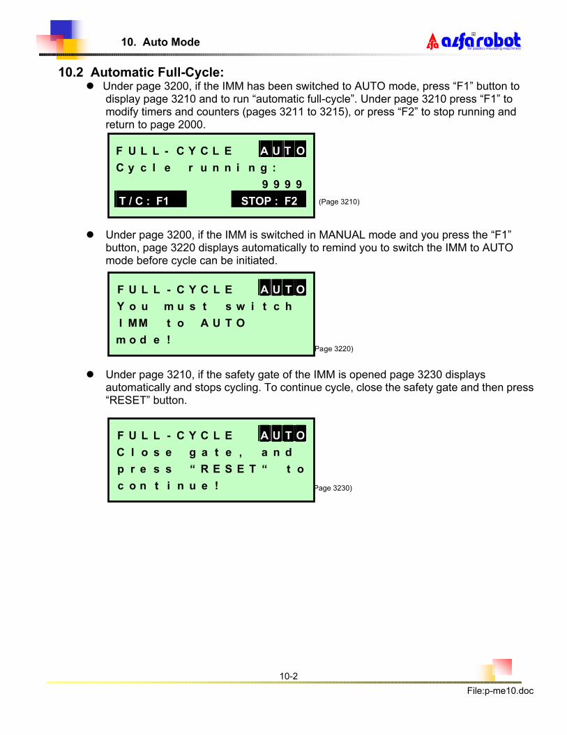
10.2 Automatic Full-Cycle: � Under page 3200, if the IMM has been switched to AUTO mode, press “F1” button to
display page 3210 and to run “automatic full-cycle”. Under page 3210 press “F1” to modify timers and counters (pages 3211 to 3215), or press “F2” to stop running and return to page 2000.
(Page 3210)
� Under page 3200, if the IMM is switched in MANUAL mode and you press the “F1” button, page 3220 displays automatically to remind you to switch the IMM to AUTO mode before cycle can be initiated.
(Page 3220)
� Under page 3210, if the safety gate of the IMM is opened page 3230 displays automatically and stops cycling. To continue cycle, close the safety gate and then press “RESET” button.
(Page 3230)
F U L L - C Y C L E A U T O
C y c l e r u n n i n g :
9 9 9 9
T / C : F1 STOP : F2
F U L L - C Y C L E A U T O
Y o u m u s t s w i t c h
I M M t o A U T O
m o d e !
F U L L - C Y C L E A U T O
C l o s e g a t e , a n d
p r e s s “ R E S E T “ t o
c o n t i n u e !

10. Auto Mode
10-3
File:p-me10.doc
�R
10.3 Automatic Single-Cycle:
� Under page 3200, if the IMM is in the MANUAL mode, you may press “F2” button to run “automatic single-cycle” (Page 3240 displays automatically). After completion of one cycle you can press “F1” button to run another “single cycle”, or press “ESC” button to return to page 2000. Mold open signal must be present to allow cycle to start. Note: if the mold is open, the robot will start a cycle as soon as “F2” is pressed.
(Page 3240)
� Under page 3200, if the IMM is in the AUTO mode and you press the “F2” button, page 3250 displays automatically to remind you to switch the IMM to MANUAL mode before single cycle can be initiated.
(Page 3250)
S I N G L E - C Y C L A U T O
Y o u m u s t s w i t c h
I M M t o M A N U A L
m o d e !
S I N G L E - C Y C L A U T O
P r e s s “ F 1 “ t o r u n
a g a i n , o r p r e s s
“ E S C “ t o e x i t .

10. Auto Mode
10-4
File:p-me10.doc
�R
10.4 Timers and Counters
� During “automatic full-cycle” under page 3210, you can press “F1” button to view and modify all the motion delay timers via pages 3211 thru 3213 Use cursor keys to select value and +/- keys to change value.
Note: Press “Page Down” button to go next page, or “ESC” button to return to page 3210.
(Page 3211)
(Page 3212)
(Page 3213) � Under page 3213, to view and modify counters press “Page Down” button to go to page
3214 and again for page 3215.
(Page 3214)
� Under page 3214, you can press “F1” button to reset the counter to zero, or press “F2” to go to page 3215.
(Page 3215)
� Under page 3215, you can modify counter and timer for the auxiliary equipment (conveyor or spraying device) but you won’t be able to activate the Aux device here.
� 0. 03 0. 03 AUTO
0. 03 0. 03
0. 03 0. 03
0. 03 0. 03 2/5
� 0. 03 � 0. 04 AUTO
0. 04 � 0. 04
� 0. 04 0. 04
� 0. 04 0. 04 1/5
C Y C - C O U N T E R 4 / 5
P r e - s e t : 9 9 9 9
C u r r e n t : 9 9 9 9
Z E R O : F 1 A U X I : F 2
A U X I L I A R Y 5 / 5
( C o n v . o r S p r a y )
C o u n t e r : 0 0
T i m e r : 0 0 . 0 0 ( s e c )
� 0. 03 0. 03 AUTO
0. 03 0. 03
0. 03 0. 03
0. 03 0. 03 3/5

11. Manual Mode
File:p-me11.doc
11-1
�R
11. MANUAL MODE
11.1 How to Operate: � Under page 2000, press “F2” button to display page 4000.
(Page 4000)
� Under page 4000, press any motion button to operate the robot manually.
� Definition of all manual motion buttons are:
Function Key (1), view inputs and outputs. Function Key (2), view system data. Page- Down Key, switch screens. Escape Key, when various operational functions are entered, press to escape.
Arm Up Key Arm Down Key Kick Back Key Kick Forward Key Swing In Key Swing Out Key Gripper Close Key Gripper Open Key
Vacuum ON Key Vacuum OFF Key
M A N U A L M O D E
P r e s s a n y m o t i o n
k e y t o o p e r a t e !
I / O: F1 SYSTM: F2

11. Manual Mode
File:p-me11.doc
11-2
�R
Reset Key. Enter Key.
Value Increase/Decrease Key.
In TEACH MODE, “+” Enter Mold Open.
“- ” Enter Mold Close.
Cursor Forward/Backward and Up/Down Key.
11.2 LED Indicator Lamps on the Hand-held Pendant: 1/ MO : “Mold Open ” signal
2/ MC : “Mold Close Permit” signal
3/ SG : “Safety Gate Close” signal
4/ EJE : “Ejector Forward Permit” signal
5/ VAC: “Vacuum Confirmation” signal
6/ GRP: “Gripper Confirmation” signal
11.3 Input Signals: � Under page 4000, press “F1” button to display page 4100 for the first 4 input
signals. To read the next 4 input signals press “Page Down” button, or press “ESC” to return to page 4000 at any time.
(Page 4100) (Page 4101)
� “Solid Circle” indicates ON, and “Hollow Circle” indicates OFF.
11.4 Output Signals: � Under page 4101, press “Page Down” button to display page 4102 for the first
signals. To read the next 4 output signals press “Page Down” button, or press “ESC” to return to page 4000 at any time.
(Page 4102) (Page 4103)
� “Solid Circle” indicates ON, and “Hollow Circle” indicates OFF.
11.5 System Data:
� A r m U p INPUT
� I M M A u t o
� S w i n g – I n
� S w i n g – Ou t 1 / 4
� A r m D o w n OUTPUT
� S w i n g – I n
� S w i n g – O u t
� K i c k F w d 3 / 4
� G r i p INPUT
� V a c u u m
� G a t e C l o s e
� M o l d O p e n 2 / 4
� G r i p p e r OUTPUT
� V a c u u m
� M C A b l e
� A u x i l i a r y 4 / 4

11. Manual Mode
File:p-me11.doc
11-3
�R
� Under page 4000, press “F2” button to display page 4200. With this page you will be
able to select the following data: 1) File: “lock” or “unlock”. (Once “file lock” is selected, Mode key is disabled and
program setting is not possible) 2) Robot: “in use” or “not in use”. (Once “robot not in use” is selected, page 8000 will display to remind you of this status) 3) Alarm Record: To review the last five (5) alarm records, press “F1” to display page 4300 up to 4314.
� You can press “Page Down” button to display page 4201, or press “ESC” button to return to page 4000.
(Page 4200)
� Under this page(4201) you can make a selection of auxiliary equipment to be used: 1) Spray: This indicates the use of silicon spraying device. 2) Conveyor: This indicates the use of belt conveyor.
� You can press “Page Down” button to display page 4202, or press “ESC” button to return to page 4000.
(Page 4201)
� Under this page you will be able to view the following information: 1) Cycle: This indicates “Total Number of Cycles” this robot has running after installation. 2) Ex-date: This indicates “Date of Ex-works” of this robot. 3) Version: This indicates “Version of Software” prepared by the manufacturer.
� After viewing of this page, press “ESC” button to return to page 4000.
(Page 4202)
11.6 Alarm Records:
S Y S T E M D A T A 1 / 3
F i l e : u n l o c k
R o b o t : i n u s e
A l a r m R e c o r d : F 1
S Y S T E M D A T A 2 / 3
S e l e c t a n a u x i -
l i a r y : S p r a y
P r e s s “ E N T E R “ !
S Y S T E M D A T A 3 / 3
C y c l e : 9 , 9 9 9 , 9 9 9
E x - d a t e : 0 0 _ 0 8 _ 0 8
V e r s i o n : G B 2 8 E 0 7 0

11. Manual Mode
File:p-me11.doc
11-4
�R
� Under page 4200, press “F1” button you can view the last five (5) alarm records. � Alarm message shown in page 4300 is just an example for your reference. � You can press “Page Down” button repeatedly to jump to another four pages in
sequence, or press “ESC” button to return to page 4200 at any time.
(Page 4300)
11.7 Incorrect Motions:
� Under manual mode, one of the following warning messages may be display while you are operating this robot manually: 1) Wrist rotate inhibit as arm is inside the mold. 2) Mold close inhibit as arm is inside the mold. 3) Swing-inward or swing-outward inhibit as arm is down. 4) Arm down inhibit as no mold open signal present. 5) Safety gate is open, no motion is allowed. 6) Motion key you have pressed is already made.
� Warning messages shown in page 4400 is just an example for your reference only. � Screen will return to the previous page automatically in 3 seconds.
(Page 4400)
11.8 Robot Not In Use:
� Once robot is set to “Not in Use”, page 8000 will display automatically to remind you of this status.
(Page 8000)
A L A R M R E C O R D 1 / 5
E 0 1 : A r m u p
s i g n a l i s
m i s s i n g !
I N C O R R E C T M O T I O N
W r i s t r o t a t e i n -
h i b i t a s a r m i s
i n s i d e t h e m o l d .
�R O B O T I S N O T
I N U S E ! �
P r e s s “ F 1 ” f o r
r e - a c t i n g a g a i n .

12. Mode Setting
12-1
File :p-me12.doc
○R
12. MODE SETTING (PROGRAMING)
12.1 Select a Mold Number
� Under page 2000 (Main Menu), press “MODE” button to display page 5000 for Mode Setting. Using the arrow keys select a mold number that you are going to use to store your program. Then press “ENTER” button to confirm this selection.
(Page 5000)
� If there is a program already stored in the mold number you selected, page 5100 will display. Confirm your selection of this mold number by pressing “F1” button to display page 5200, or press “ESC” button to return to page 5000.
(Page 5100) � If the mold number you have selected is empty, page 5200 will display
automatically.
12.2 Select a Program Number
� Under page 5200, select any of the following program numbers, and then press “ENTER” button: 1) Standard programs: 01 ~ 08, 2) Teachable programs: 09 ~ 20. (Page 5200)
M O D E S E T T I N G
S e l e c t a M o l d N o
( 0 1 - 5 0 ) : 0 1
P r e s s “ E N T E R ” !
R E A L L Y W A N T T O
U S E T H I S M O L D
N O ? P r e s s “ F 1 ”
t o c o v e r !
S e l e c t a P r o g N o
( 0 1 - 2 0 ) : 0 1
P r e s s “ E N T E R “ !
T E A C H : F 1 T / C : F 2

12. Mode Setting
12-2
File :p-me12.doc
○R
� Under page 5200, if you know that none of the pre-set standard programs or existing teach programs suit your application, press “F1” button to display page 5400 and teach a new program.
� If you know that the program number you have selected is what you want to save in this mold number and you would like to view timers and counters that are pre-set with the program, you can press “F2” button to display page 3211 thru 3215 for confirmation or adjustment. Note: Refer paragraph 10.4 for display.
� Under page 5200, in case the “program number you have selected does not exist”, after pressing “ENTER” button page 5201 will display for 3 seconds and then jump to page 5400 to teach a new program.
(Page 5201)
(Page 5400)
� Under page 5200, in the case that one of the “standard pre-set programs” is selected, after pressing the “ENTER” button page 5202 will display.
(Page 5202)
� Under page 5200, in the case that one of the “pre-composed teach programs” is selected, after pressing “ENTER” button page 5203 will display.
(Page 5203)
12.3 A Standard Pre-set Program is Selected:
P r o g N o y o u h a v e
s e l e c t e d i s n o t
e x i s t e d , T E A C H a
n e w p r o g r a m !
M o v e a r m t o d e -
f i n e h o m e p o s i . ,
t h e n p r e s s E N T E R
( M O : ‘ + ’ , M C : ‘ - ’ )
A S T ‘ D P R E - S E T
P R O G I S S E L E C T E D
V i e w d e t a i l s : F 1
o r p r e s s E N T E R !
A P R E - S E T T E A C H
P R O G I S S E L E C T E D
V i e w d e t a i l s : F 1
o r p r e s s E N T E R !

12. Mode Setting
12-3
File :p-me12.doc
○R
� Under page 5200, once a “standard pre-set program” is selected page 5202 will display.
(Page 5202)
� Under page 5202, you can press “F1” button to display page 5220 and view the motion sequence of this program (in case the standard pre-set program is longer than one page), to see the next page 5221 press “Page Down”, or press “ESC” to return to page 5202.
(Page 5220)
(Page 5221)
� Under page 5202, you can press “ENTER” button to confirm your selection of program to be saved in this mold number, page 5222 will then display to enable you to make a selection of the following EOAT detection method:
1) “Gripper Sensor” only. 2) “Vacuum Sensor” only. 3) Both “Gripper and Vacuum Sensors”. (Page 5222)
� After a selection of EOAT detection method is made, press “ENTER” button page
A S T ‘ D P R E - S E T
P R O G I S S E L E C T E D
V i e w d e t a i l : F 1 ,
o r p r e s s E N T E R !
� 0. 03 � 0. 03 STD
0. 03 � 0. 03 01
� 0. 03 0. 03
� 0. 03 0. 03 1/2
� 0. 03 0. 03 STD
01
2/2
S e l e c t a n E - O - A
c h e c k i n g m e t h o d :
G R I P
P r e s s “ E N T E R ” !

12. Mode Setting
12-4
File :p-me12.doc
○R
5300 will display to confirm that the program has been saved.
(Page 5300)
12.4 A Pre-set Teach Program is Selected:
� Under page 5200, if a “pre-set teach program” is selected page 5203 will display.
(Page 5203)
� Under page 5203, you can press “F1” button to display page 5230 and view the motion sequence of this teach program, to see next page 5231 press “Page Down”, or press “ESC” to return to page 5203.
(Page 5230)
(Page 5231)
� Under page 5203, press “ENTER” button page 5300 will display to confirm that the program has been successfully saved.
N E W L Y C O M P O S E D
M O D E S E T T I N G H A S
B E E N S U C C E S S F U L -
L Y S A V E D !
A P R E - S E T T E A C H
P R O G I S S E L E C T E D
V i e w d e t a i l : F 1 ,
o r p r e s s E N T E R !
0. 03 0. 03 TEACH
� 0. 03 � 0. 03 09
0. 03 � 0. 03
� 0. 03 0. 03 1/2
0. 03 � 0. 03 TEACH
0. 03 � 0. 03 09
2/2
N E W L Y C O M P O S E D
M O D E S E T T I N G H A S
B E E N S U C C E S S F U L -
L Y S A V E D !

12. Mode Setting
12-5
File :p-me12.doc
○R
(Page 5300)
12.5 Teach A New Program:
� Upon entering into “teach mode”, page 5400 will display first to remind you to define home position for this program. Press manual motion buttons to move arm to define the initial start-up position and then press “ENTER”.
� This page also reminds you to press “+” button to act as “Mold Open” and press “-“ button to act as “Mold Close” while teaching a new program. Mold close is the step in the sequence where the robot allows the IMM to close mold.
(Page 5400)
� Under page 5400, once “ENTER” button is pressed, a “blank” page 5401 will
display. First, you will have to press “+” button to enter “Mold Open” as the first
step of any teach program, and then press motion buttons to carry out the desired steps. You must press enter after each step.
� Press “F2” button to save if total number of steps is less than nine (9), or it will automatically jump to page 5402 to continue sequence input. However, you must press “F2” button when you have completed your inputting the teach sequence. Note: 1) After each step is input you must press “ENTER” or it won’t jump to the next step. Do not forget to press enter after each step.
2) During teaching do not forget to press “─” button to enter “Mold
Close” as part of the in the sequence or you won’t be able to successfully complete the input. Mold close is the step in the sequence when the robot has cleared the mold area and the next molding cycle may begin.
(Page 5401)
M o v e a r m t o d e -
f i n e h o m e p o s i . ,
t h e n p r e s s E N T E R
( M O : ‘ + ’ , M C : ‘ - ’ )
� �
� � TEACH
� � �
� P1
� �
�
P r e s s F 2 t o s a v e
�
� TEACH
P2
P r e s s F 2 t o s a v e

12. Mode Setting
12-6
File :p-me12.doc
○R
(Page 5402)
� After pressing “F2” button for saving, page 5403 may display for 3 seconds to remind you that your teaching of a new program was not complete, the control will then return to “blank” page 5401 to begin input from start.
(Page 5403)
� Once “teach a new program” is successfully completed, page 5404 will then display. You can now select a program number to save it under (09 to 20) and then press “F1” button so that the new teach program can be saved there.
(Page 5404)
� Page 5405 will display if the program number that you have selected a program that has been used previously, you can press “F1” button to say “yes” or press “ESC” button to return to page 5404 for selecting of another program number.
(Page 5405)
� Under page 5405, press “F1” button and page 5406 will display to confirm that you have successfully saved the new teach program in the “Program Number” you have selected. This page is also displayed when an unused program number is selected from page 5404.
A T T E N T I O N ! !
I n c o m p l e t e T E A C H
s e q . , a r m m u s t
r e t u r n t o H O M E .
T E A C H M O D E
S e l e c t a P r o g N o
( 0 9 - 2 0 ) : 0 9
P r e s s “ E N T E R ” !
R E A L L Y W A N T T O
R E P L A C E P R O G R A M
N O ? P r e s s “ F 1 ”
t o c o v e r !
N E W L Y E N T E R E D
T E A C H P R O G H A S
B E E N S U C C E S S -
F U L L Y S A V E D !

12. Mode Setting
12-7
File :p-me12.doc
○R
(Page 5406)
T E A C H M O D E
S e l e c t a P r o g N o
( 0 9 - 2 0 ) : 0 9
P r e s s F 1 t o s a v e

13. Erasing System Data
13-1
File:p-me13.doc
�R
13. ERASING SYSTEM DATA
� Under page 2000, press , and buttons consecutively until all three
buttons are pressed page 9000 will display.
(Page 9000)
� Under page 9000, press “F1” button the following page will display until all stored data are completely cleared.
(Page 9001)
� When the erasing action is completed, turn main power OFF and then re-start the robot again.
[CAUTION]
ERASING SYSTEM DATA it will erase all Mold No. data in EPROM including Teach Programs, timer settings, mold No. memory and so on. Unless robot data has been corrupted, do not perform this action.
E - P R O M C L E A R E D
� R E A L L Y W A N T T O
E R A S E S Y S T E M
D A T A ? � P r e s s
“ F 1 ” t o e r a s e !

14. Troubleshooting
14-1
File:p-me14.doc
�R
14. TROUBLE SHOOTING
14.1 Troubleshooting Codes
(1) E01: Arm Up Signal is missing!
(2) E02: IMM Auto Mode Signal is missing!
(3) E03: Swing-in Signal is missing!
(4) E04: Swing-out Signal is missing!
(5) E05: Gripper Signal is missing!
(6) E06: Vacuum Suction Signal is missing!
(7) E11: Arm Up/Down Valve is faulty!
(8) E13: Swing-in Valve is faulty!
(9) E14: Swing-out Valve is faulty!
(10) E16: Swing-in/out signals both lit simultaneously!
(11) E17: Swing-in/out signals both missing!
NOTE: In case a Trouble/Alarm is incurred, press “RESET” button and return
to Main Menu (page 2000) for troubleshooting.

14. Troubleshooting
14-2
File:p-me14.doc
�R
14.2 Troubleshooting
1. E01: Arm Up Signal is Missing!
Check distance between Arm Up Sensor and Sensing Plate to see if it is Within 2 ~ 3mm?
Adjust distance to 2~3mm or until indicator lamp on the sensor is ON.
Yes
Check indicator lamp on the Arm Up Sensor to see if it is ON? Replace the Arm Up Sensor.
Yes
Jump to screen page 4100 to monitor If Arm Up Signal is ON? Replace the Arm Up Sensor.
Yes
Check Arm Up motion to see if it is to Slow? Notify Plastic Process Equipment.
Yes
Adjust Arm Up speed control valve to faster speed.
No No No No
2. E02: IMM Auto Mode Signal is Missing!
1) Jump to screen page 4100 to monitor if IMM Auto signal is turned OFF?
2) Check if IMM has been switched to Manual Mode?
3. E03: Swing-in Signal is Missing!
Method of troubleshooting is the same as the flow diagram for E01.
4. E04: Swing-out Signal is Missing!
Method of troubleshooting is the same as the flow diagram for E01.

14. Troubleshooting
14-3
File:p-me14.doc
�R
5. E05: Gripper Signal is Missing!
Check to see if the gripper grips Correctly?
Open safety gate and move arm to fully up position under manual mode, and then re-adjust the gripper.
Yes
Is action of the gripper sensor normal? (Gripper Closed: Indicator
ON, Gripper Open: Indicator OFF) Re-adjust sensor to correct position.
Yes
Is gripper sensor wire broken? Re-adjust sensor to correct position.
Yes
Replace the wire or entire sensor.
No
No No
6. E06: Vacuum Suction Signal is Missing!
Is action of the vacuum suction normal?
Open safety gate and move arm to fully up position under manual mode, and then re-adjust the suction cups.
Yes
Check if there is air leaking or sensor wire broken?
Either the vacuum generator or the vacuum sensor is at fault.
Yes
Replace the wire or entire sensor.
No No

14. Troubleshooting
14-4
File:p-me14.doc
�R
7. E11: Arm Up and Down Solenoid Valve is Faulty!
Check to see if arm moves to fully down position?
Adjust Arm Down speed control valve to see if arm can move to fully down position?
Yes No
Jump to screen page 4102 to monitorIf Arm Down Signal is ON?
Either Arm Up/Down solenoid valve or speed control valve is faulty.
Yes
Arm Down Sensor is faulty.
No No
No
Notify Plastic Process Equipment.
8. E13: Swing-in Solenoid Valve is faulty!
Method of troubleshooting is the same as inspection flow for E11.
9. E14: Swing-out Solenoid Valve is in faulty!
Method of troubleshooting is the same as inspection flow for E11.
10. E16: Swing-in and Swing-out Signals are lit simultaneously!
Check to see if indicator lamp on the Swing–in and Swing–out sensors are both ON?
Jump to screen page 4102 to monitor if Swing-in and Swing-out Signal are both ON?
Yes No
Re-adjust both sensors to see if they are now working correctly?
No Yes No
Notify Plastic Process Equipment.
11. E17: Swing–in and Swing–out Signals are both missing!
Method of troubleshooting is the same as inspection flow for E16.

A. Auxiliary Control Circuit
A-1
�R
Apendix A, Control of Auxiliary Equipment (Sprayer/ Conveyor)
The robot control provides an output signal that may be used to control an auxiliary device
like a conveyor or sprayer. This output is in the form of a single normally open dry contact
on relay K5, Connection to this circuit may be made on the terminal strip “CAN” located on
the inside of the door of the robot control box. (See section 6.5 for location.)
1 The output is controlled as follows:
a. When Sprayer is selected. K5 closes as the “Allow Mold Close” line of the robot
program is read. K5 remains closed for the amount of time programmed in the timer
section of the program that is running. (See section 4 for timer setting) The mold
close enable output signal is not made until the timer times out. The cycle counter
controls the frequency of the spray action. If the counter is set to 3 then the sprayer is
activated every third cycle. (See section 3 for counter setting)
b. When conveyor is selected. K5 closes at the end of the robot program. K5 stays
closed for the amount of time set on the timer. (See section 3 for timer setting) In this
mode K5 closes every cycle.
2 Sprayer/ conveyor is selected as follows
a. From the main menu press F2 for manual Mode
b. From manual mode press F2 for System
c. From the System page press page down to get to page 2/3.
d. Use +/- to change between Sprayer and Conveyor
e. Press Esc to return to Manual Mode Menu
3 Setting the Timer and Counter
a. Auxiliary timer controls how long the relay K5 stays closed when activated. Aux
counter controls the frequency of K5 activation during Sprayer Mode.
From the Main menu press F1 to select Auto Mode

A. Auxiliary Control Circuit
A-2
�R
From the Auto mode select the Mold Number you wish to run/modify
Press F1 to start
Page down until page 4/5 “CYC-Counter”
Press F2 for Aux page 5/5.
Use arrow keys to select field and +/- keys to change value.
Press Esc key to exit.
Press F1 to select timers/counters.
Note: If you do not want K5 to activate, set timer to 0.0

A. Auxiliary Control Circuit
A-3
�R

2-14 SPI Interface Definition 2-13
PIN#1 PIN#2
1 9 EMERGENCY STOP ( I.M.M )
While the injection molding machine emergency stop is activated, the circuit will open and will activate the emergency stop circuit of the robot. The injection molding machine emergency stop circuit will be hard wired in series with the robot emergency stop circuit. The current of this signal must not exceed 6 amps
2 16 MOLD FULLY OPEN ( I.M.M)
This signal is present when the contacts are closed and indicates that the mold is in a predetermined fully open position. The signal is maintained whenever the mold is the predetermined fully open position.
3 11 MOVABLE GATES CLOSED (I.M.M )
This signal is present when the contacts are closed and indicates that the movable gates and guard that prevent access to robot motions are closed. The signal maintained as long as the movable gates and guard are closed.
4 16 EJECTOR FULLY RE-TRACTED
This signal is present when the contacts are closed and indicates that the ejector are fully retracted. The signal is maintained while the ejectors are fully retracted
5 16 EJECTOR FULLY FOR-WARD
This signal is present when the contacts are closed and indicates that the ejectors are fully forward. The signal is maintained while the ejectors are fully forward
6 16 CORE FULLY SET This signal is present when the contacts are closed and indicates that the cores are fully set. The signal is maintained while the ejectors are fully forward.
7 16 CORE FULLY PULLED This signal is present when the contacts are closed and indicates that the cores are fully pulled. The signal is maintained while the cores are fully pulled
8 16 REJECT PART This signal is present when the contacts closed and indicates that the molded part is not acceptable. The signal must be given on/or before the mold fully open signal and removed with the start of mold closing.
10 16 FULLY AUTOMATIC This signal is present when the contacts are closed and indicates that the mode of operation of the injections molding machine is fully automatic. This signal is maintained as long as the injection molding machine is in fully automatic
12 16 MOLD FULLY CLOSED This signal is present when the contacts are closed and indicates that the injection molding machine ahs reached tonnage set point. The signal is maintained as long as the mold is fully closed.
15 16 NO PART AVALABLE This signal is present when the contacts are closed and indicates that no molded part is available. The signal must be given before the start of mold opening and removed with the start of mold clos-ing.
SIGNAL ( FROM IMM TO ROBOT )
PIN#1 PIN#2
17 32 PERMIT CLAMP CLOSE The closing of this contact indicates that the robot is in a predetermined safe position and allows the IMM clamp to close. Clamp closing motion must be interrupted whenever this signal is not present. This signal is no longer required once the mold is fully closed.
18 26 PERMIT CLAMP MOTION The closing of this contact indicates that the robot is in a predetermined safe position and allows IMM clamp motion. Both clamp closing and clamp opening motion must be interrupted whenever this signal is not present. The current of this signal must not exceed 6 amps
19 27 EMEGENCY STOP While the robot emergency stop is activated, the circuit will open and activate the emergency stop circuit of the injection molding machine. The robot emergency stop circuit will be hardwired in series with the injection molding machine emergency stop circuit. The current of this signal must not exceed 6 amps.
20 32 ROBOT NON-OPERATIONAL
The switch contact is open when the I.M.M is operated with the robot. The switch is closed when the machine is operated without the robot. When the switch is closed, the signal permit Clamp Close (17,32) Permit Clamp Motion (18,26) and Emergency Stop ( Robot ) (19,27 ) are still moni-tored. All other signals can be in an undetermined state.
21 32 PERMIT EJECTOR RE-TRACT
The closing of this contact permits the ejectors to retract. This signal is maintained until the ejectors are fully retract.
22 32 PERMIT EJECTOR FOR-WARD
The closing of this contact permits the ejectors to go forward. The signal is maintained until the ejectors are fully forward.
23 32 PERMIT CORE PULL The closing of this contact permits the cores to be pulled. The signal is maintained until the cores are fully pulled.
24 32 PERMIT CORE SET The closing of this contact permits the cores to be set. The signal is maintained until the cores are fully set.
SIGNAL ( FROM ROBOT TO IMM)

2-15 SPI and Top Swing Sprue Picker Interface connector number ( For SPI )
2-14
PICKER SPI SOCKET
PIN
SOCKET
SPI PIN TOP PIN SPI PIN TOP PIN SIGNAL ( FROM IMM TO ROBOT )
1 IEG 9 IEP EMERGENCY STOP ( I.M.M )
2 F 16 C MOLD FULLY OPEN ( I.M.M)
3 E 16 C MOVABLE GATES CLOSED (I.M.M )
4 16 EJECTOR FULLY RETRACTED
5 16 EJECTOR FULLY FORWARD
6 16 CORE FULLY SET
7 16 CORE FULLY PULLED
8 16 REJECT PART
10 16 FULLY AUTOMATIC
12 D 16 and 11 C1 MOLD FULLY CLOSED
15 16 NO PART AVALABLE
SPI PIN TOP PIN SPI PIN TOP PIN SIGNAL ( FROM ROBOT TO IMM)
17 L 32 K PERMIT CLAMP CLOSE
18 J 26 I PERMIT CLAMP MOTION
19 REIN 27 REOUT EMERGENCY STOP
20 32 ROBOT NON-OPERATIONAL
21 32 PERMIT EJECTOR RETRACT
22 N 32 M PERMIT EJECTOR FORWARD
23 32 PERMIT CORE PULL
24 32 PERMIT CORE SET
A, B : AC 110 V Others : See Left
NOTE 1 SPI robot Interface has a number of signals. It is not necessary to connect all the SPI robot interface signal to the TOP
series Sprue Picker. Connect A,B to power (AC 110 Volt ) and connect the wiring as shown above.
You may not find a Cycle start signal from picker to Injection Molding Machine at SPI robot interface. Concerning SPI
interface, please contact your machine builder with any question. ( E-STOP Function (IEG,IEP, REIN, REOUT) was
added after the machine S/N : 04011301 ) : Jumper in the Robot SPI plug
NOTE 2
To operate molding machine without Robot, operation Disconnect Robot SPI plug from Molding Machine and connect
SPI dummy plug which was plugged in the molding machine. ( Robot Non– Operational and other permits function should
be jumper in the dummy plug )