Embed Size (px)
Citation preview

School of Engineering Science Simon Fraser University
Burnaby, BC V5A 1S6
Home Care Robot PRAlpha Inc.
March 6, 2008Page 1 of 1
PPRRAAllpphhaa RRoobboottiiccss IInncc.. PPRRAAllpphhaa RRoobboottiiccss IInncc..
Monday, March 3, 2008 Patrick Leung School of Engineering Science Simon Fraser University Burnaby, B.C. V5A 1S6 Re: ENSC 305/440 Design Specification of Home Care Robot Dear Mr. Leung, I am glad to present our proposed design of building a robot for the remote home care purpose. To meet the requirements listed in our functional specifications, we proposed a complete solution to build a reliable system at a reasonable cost. Modulated design increases the flexibility and extensibility of the system. Please read the attached document, Design Specification of the Home Care Robot, for details. If you have any concerns or questions regarding this project, please contact us by email, [email protected]. Sincerely,
Rick Wong (CEO), PRAlpha Robotics Inc. Enclosure: Design Specification of Home Care Robot
PRAlpha Robotics Inc.
Design Specification for the Home Care Robot
Issue Date: March 7, 2008
Version : 1.0
Document ID : ETC-003
Project Team: Rick Wong Jessica Sun Feng Ye
Contract Person: Rick Wong [email protected]
Submitted to: Patrick Leung Steve Whitmore Mike Sjoerdsma Brad Oldham
Proprietary and Confidential © Copyright 2007 PRAlpha Robotics Inc. All rights reserved. No part of this publication
may be used or reproduced in any form by any
means without prior written permission from
PRAlpha Robotics Inc.
Design Specification for the Home Care Robot
ETC‐003 1.0
Simon Fraser University ENSC 305/440 Capstone Project
March 7, 2008Page 2 of 2
PPRRAAllpphhaa RRoobboottiiccss IInncc.. PPRRAAllpphhaa RRoobboottiiccss IInncc..
Document Information
Document Name Design Specification for the Home Care Robot
Document ID ETC-003
Version 1.0
Issue Date March 7, 2008
Reference Documents
Reference Document ID Title, Version, Date
1 ETC-001 Proposal for a Home Care Robot, V1.0, Jan 21, 2008
2 ETC-002 Functional Specification for the Home Care Robot, V1.0, Feb 18, 2008
3. HL-001 Project Overview High Level Design, V2.0, Nov 23, 2007
4. HL-002 GUI High Level Design, V2.0, Oct 20, 2007
5. HL-003 SCM High Level Design, V1.0, Nov 17, 2007

Design Specification for the Home Care Robot
ETC‐003 1.0
Simon Fraser University ENSC 305/440 Capstone Project
March 7, 2008Page 3 of 3
PPRRAAllpphhaa RRoobboottiiccss IInncc.. PPRRAAllpphhaa RRoobboottiiccss IInncc..
Revision History
Issue Author(s) Date Description
0.1 Rick Wong March 02, 2008 Creation System Overview BUS Power System
0.2 Feng Ye March 03, 2008 Action Control Module Computer System
0.3 Jessica Sun March 03, 2008 Executive Summary Introduction Conclusion
0.4 Rick Wong March 4, 2008 Microntroller Center Manager Module Sensor Control Moudle
0.5 Rick Wong March 5, 2008 User Define Module
0.6 Jessica Sun
March 6, 2008 Chassis System Test Plan Reference
0.7 Rick Wong March 6, 2008 Review and Editing
1.0 Rick Wong March 6, 2008 Appendix

Design Specification for the Home Care Robot
ETC‐003 1.0
Simon Fraser University ENSC 305/440 Capstone Project
March 7, 2008Page 4 of 4
PPRRAAllpphhaa RRoobboottiiccss IInncc.. PPRRAAllpphhaa RRoobboottiiccss IInncc..
Executive Summary
For remote home care purpose, the development team of PRAlpha Inc. is building a multi-functional robot, iBonni. For home secure usage, house owners can remotely access robot from anywhere via internet and drive it to monitor their houses through night vision camera mount on iBonni. Using the powerful built-in sensor system, iBonni can take the roles of smoke detector, flood detector, temperature detector, etc and generate alert in case of emergency. Besides security applications, iBonni can act as a universal IR controller that accepts commands from remote user and operates other devices which support IR control protocol. As a design specification for the home care robot, this document details our design choices which are made to meet all the requirements listed in the Functional Specification for the Home Care Robot [1]. Our design is based on the requirements intended for both of prove-of-concept and production devices in the functional specification, and not includes the requirements that are only for production device. In this document, we will compare several design approaches to achieve our purpose, discuss the proper justifications for valid design choices and elaborate on our design specifications. System diagrams and flow charts for modules and a system test plan will be included. In our first development phase, a prototype of the home care robot will be completed. The movements of the robot will be remotely controlled via Internet and users can monitor their home through a camera attached on the robot. For demonstration purpose, iBonni will be able to report environment temperature and distance from road blocks as well as send various IR control signals upon requests. As scheduled in our proposal, this phase will be finished by the beginning of April, 2008.
Design Specification for the Home Care Robot
ETC‐003 1.0
Simon Fraser University ENSC 305/440 Capstone Project
March 7, 2008Page 5 of 5
PPRRAAllpphhaa RRoobboottiiccss IInncc.. PPRRAAllpphhaa RRoobboottiiccss IInncc..
Table of Contents
Document Information .........................................................................................................2 Reference Documents ..........................................................................................................2 Revision History ..................................................................................................................3 Executive Summary .............................................................................................................4 Table of Contents .................................................................................................................5 List of Figures ......................................................................................................................7 List of Tables ........................................................................................................................8 Acronyms .............................................................................................................................9 Glossary .............................................................................................................................10 1 Introduction ................................................................................................................. 11
1.1 Scope ........................................................................................................................... 11 1.2 Intended Audience ....................................................................................................... 11
2 System Requirements..................................................................................................12 2.1 System Overview ........................................................................................................ 12 2.2 High- level System Design .......................................................................................... 13 2.3 Safety Considerations: ................................................................................................. 14 2.4 Environmental Considerations .................................................................................... 14
2.4.1 RoHS Compliant ................................................................................................... 14 2.4.2 E & M Interfere ..................................................................................................... 14 2.4.3 Noise ..................................................................................................................... 14
3 Microcontroller ...........................................................................................................15 4 Center Manager Module .............................................................................................17 5 Sensor Control Module ...............................................................................................19
5.1 Temperature Sensor ..................................................................................................... 21 5.2 Block Sensor................................................................................................................ 21
6 Action Control Module ...............................................................................................24 6.1 Motor ........................................................................................................................... 24 6.2 Action Control ............................................................................................................. 26
7 Computer System ........................................................................................................27 7.1 Mainboard and Process ............................................................................................... 27 7.2 Stream Sever: .............................................................................................................. 28 7.3 Control Daemon .......................................................................................................... 28 7.4 User Interface .............................................................................................................. 28 7.5 Command Words ......................................................................................................... 30
Design Specification for the Home Care Robot
ETC‐003 1.0
Simon Fraser University ENSC 305/440 Capstone Project
March 7, 2008Page 6 of 6
PPRRAAllpphhaa RRoobboottiiccss IInncc.. PPRRAAllpphhaa RRoobboottiiccss IInncc..
7.6 Microcontroller Programming ..................................................................................... 31 8 User Defined Module ..................................................................................................32 9 BUS .............................................................................................................................35 10 Power Module .............................................................................................................37 11 Chassis ........................................................................................................................39
11.1 Base Mechanical design .............................................................................................. 39 11.2 Components Placement: .............................................................................................. 40
12 System Test Plan .........................................................................................................42 12.1 Module Unit Test Plan ................................................................................................. 42
12.1.1 Center Manager Module........................................................................................ 42 12.1.2 Action Control Module ......................................................................................... 42 12.1.3 Sensor Control Module ......................................................................................... 42 12.1.4 User Defined Module ............................................................................................ 42 12.1.5 Power Module ....................................................................................................... 42
12.2 Functionality Test Plan ................................................................................................ 43 12.2.1 Test Case 1: Mobility ............................................................................................ 43 12.2.2 Test Case 2: Temperature Sensory ........................................................................ 43 12.2.3 Test Case 3: Block Sensory ................................................................................... 43 12.2.4 Test Case 4: User Control ...................................................................................... 44
12.3 Overall System Test Plan ............................................................................................. 44 13 Conclusion ..................................................................................................................45 Appendix A: Data Sheet .....................................................................................................46 References ..........................................................................................................................47
Design Specification for the Home Care Robot
ETC‐003 1.0
Simon Fraser University ENSC 305/440 Capstone Project
March 7, 2008Page 7 of 7
PPRRAAllpphhaa RRoobboottiiccss IInncc.. PPRRAAllpphhaa RRoobboottiiccss IInncc..
List of Figures
Figure 1: System Sketch ....................................................................................................12 Figure 2: System Block Diagram V3.0 ..............................................................................13 Figure 3: Pin configurations of ATMega168 .....................................................................16 Figure 4: CMM Task Flow Chat ........................................................................................18 Figure 5: Sensor System Block Diagram ...........................................................................19 Figure 6: SCM Flow Chat ..................................................................................................20 Figure 7: SRF05 Timing Diagram .....................................................................................23 Figure 8: Pin Connection for 2-Pin Trigger/Echo Mode ...................................................23 Figure 9: Stepper Motor Operation ....................................................................................24 Figure 10: Circuit Drawing of Stepper Motor Controller ..................................................25 Figure 11: ACM Task Flow Chart ......................................................................................26 Figure 12: GUI Task Flow Chart .......................................................................................29 Figure 13: Handheld Remote Infrared Messages ...............................................................32 Figure 14: Resting Time between Two IR Messages .........................................................32 Figure 15: IR Message Timing Diagram ...........................................................................33 Figure 16: UDM Flow Chat ...............................................................................................34 Figure 17: BUS Interconnection ........................................................................................35 Figure 18: Arbitration between two masters ......................................................................36 Figure 19: Tank Base Side View and Base View ...............................................................39 Figure 20: Tank Base Scenograph .....................................................................................40 Figure 21: Components Placement Diagram .....................................................................41

Design Specification for the Home Care Robot
ETC‐003 1.0
Simon Fraser University ENSC 305/440 Capstone Project
March 7, 2008Page 8 of 8
PPRRAAllpphhaa RRoobboottiiccss IInncc.. PPRRAAllpphhaa RRoobboottiiccss IInncc..
List of Tables
Table 1: Comparison of Microcontrollers ..........................................................................16 Table 2: Comparison of Temperature Sensors ...................................................................21 Table 3: Comparison of Ultrasonic Sensors .......................................................................22 Table 4: Stepper Motor Specification ................................................................................25 Table 5: Comparison of Mainboard ...................................................................................27 Table 6: Command Words Types .......................................................................................30 Table 7: MCU Reset ...........................................................................................................30 Table 8: Sensor Control .....................................................................................................30 Table 9: Motor Control ......................................................................................................30 Table 10: UDM Control .....................................................................................................31

Design Specification for the Home Care Robot
ETC‐003 1.0
Simon Fraser University ENSC 305/440 Capstone Project
March 7, 2008Page 9 of 9
PPRRAAllpphhaa RRoobboottiiccss IInncc.. PPRRAAllpphhaa RRoobboottiiccss IInncc..
Acronyms
Term Definition
ACM Action Control Module
ANSI American National Standards Institute
CMM Center Manager Module
DIP Dual In-lin Package
I2C Inter-Integrated Circuit, a mutli-master serial BUS
IR Infrared
LUT Look Up Table
MCU Micro Conroller Unit
MLF Micro Lead Frame, a type of scale microchip package
QFN Quad Flat No leads Package, used with surface mounted PCB
PCB Printed Circuit Board
PWM Pulse-Width Modulation
SCM Sensor Control Module
TQFP Thin Quad Flat Pack, used in space-conscious application, PC cards
TWI Two-Wire serial Interface
UDM User Defined Module
USART Universal Synchronous/Asynchronous Receiver/Transmitter
USB The Universal Serial Bus

Design Specification for the Home Care Robot
ETC‐003 1.0
Simon Fraser University ENSC 305/440 Capstone Project
March 7, 2008Page 10 of 10
PPRRAAllpphhaa RRoobboottiiccss IInncc.. PPRRAAllpphhaa RRoobboottiiccss IInncc..
Glossary
Term Definition
Authenticate The system confirm the user’s identity by verifying the input password
Control Daemon A multi-threaded program running in the background to provide TCP/IP connection of the GUI client. It transfers the commands from the GUI client to the Robot and also transfers messages from the Robot to the GUI client
GUI Client The program with Graphic User Interface used to control the robot and display messages from the robot
Input Capture Channel A method of dealing with input signals in an embedded system
IR Controller Infrared sender used by the robot to control electrical devices
Java run-time libraries A set of computer files and programs installed on a computer so that Java programs can run on it
Public computer A computer provided in public locations like libraries, air port, hotels or Internet cafes
Stand-alone application A computer program that can be executed alone without the help of other programs
Stream Server A program that provides video stream through HTTP protocol
Ultrasonic sound with a frequency greater than the upper limit of human hearing.
Web-based GUI A Graphic User Interface run inside the web browser, it is connected to a web server and uses the services of that web server
Wi-Fi Wireless local networking technology based on 802.11 standards
Wireshark A free packet sniffer computer application for network analysis

Design Specification for the Home Care Robot
ETC‐003 1.0
Simon Fraser University ENSC 305/440 Capstone Project
March 7, 2008Page 11 of 11
PPRRAAllpphhaa RRoobboottiiccss IInncc.. PPRRAAllpphhaa RRoobboottiiccss IInncc..
1 Introduction
PRAlpha Inc. proposes developing a mobile robot, iBonni, which acts as an interface for household between home and remote site. iBonni can be controlled by an easy to use web GUI via Internet. User’s command can be sent back home to control devices. Furthermore, its sensor system can report the surrounding situations of iBonni, for example, the temperature and the distance of blocks. People also can view their home though iBonni’s eye, a night version camera. This design specification will outline our design considerations of the home care robot and offer our justifications.
1.1 Scope This document fully describes the design considerations for iBonni. For demonstration purpose, our design specification will meet most of the requirements for the proof-of-concept system which are marked A or B in Functional Specification for the Home Care Robot [1]. This document will also include software process flow charts and test plans for the system. Sufficient information for implementation phase of this project will be discussed here.
1.2 Intended Audience This document is primarily created for the PRAlpha project team to provide an implementation and development outlines. The team members will use it as design guideline for the project. The team manager will use it to measure the development progress and implementation objectives. The design engineers will use it to ensure their product design meets the requirements. The est engineers will follow the test plan specified in this document for their testing.

Design Specification for the Home Care Robot
ETC‐003 1.0
Simon Fraser University ENSC 305/440 Capstone Project
March 7, 2008Page 12 of 12
PPRRAAllpphhaa RRoobboottiiccss IInncc.. PPRRAAllpphhaa RRoobboottiiccss IInncc..
2 System Requirements
2.1 System Overview This robot, iBonni, is a center command device which interface home and remote site. As shown in Figure 1, households can remotely control and monitor iBonni by accessing a web based GUI in favor Internet Brower. The sensor system and cameras installed on iBonni will provide the real time status and feedback to the user. The user can choose to be text messaged on his cell phone in cases of fire, gas or water leaking emergency situations. On the other hand, iBonni can pass the command inputted in GUI to other home devices such as pet feeder, plant watering system and light switches via IR transmission.
Figure 1: System Sketch1
1 Figure 1’s robot ICO is from Parallax Inc and other ICOs are from Microsoft Word Resources.
iBonni
IR transmission Internet
House owner
Wireless network
Monitor house
Detect fire
Control doors &windows
Control water plant device
Detect water leak
Detect gas leak
Control lights
Control pet feeder

Design Specification for the Home Care Robot
ETC‐003 1.0
Simon Fraser University ENSC 305/440 Capstone Project
March 7, 2008Page 13 of 13
PPRRAAllpphhaa RRoobboottiiccss IInncc.. PPRRAAllpphhaa RRoobboottiiccss IInncc..
2.2 High- level System Design In order to provide a more stable system with better performance, the system will be divided into four modules and a nano-computer as shown in Figure 2. Each module is assigned at least one dedicated microcontroller (two microcontrollers if redundancy design is required for critical modules). Nano-computer’s main responsibility is to provide a web GUI access and a video stream server. The CMM, Center Manger Module, acts as a task manager which interfaces with the nano-computer via USART protocol and communicates other modules that attached on the I2C BUS. The SCM, Sensor Control Module, controls the operations of the sensors and provides real time status. The ACM, Action Control Module, is responsible for controlling the motion of the robot. User commands received on the nano PC through CMM will be transmitted via IR protocol by the UDM, User Defined Module, to control other compatible devices at home.
Figure 2: System Block Diagram V3.0

Design Specification for the Home Care Robot
ETC‐003 1.0
Simon Fraser University ENSC 305/440 Capstone Project
March 7, 2008Page 14 of 14
PPRRAAllpphhaa RRoobboottiiccss IInncc.. PPRRAAllpphhaa RRoobboottiiccss IInncc..
2.3 Safety Considerations: As safety considerations are always the most important requirements in an engineering design, we have listed the issues which will be concerned throughout our entire robot design.
The outside shell will be made of biomaterial and have no sharp corners, edges or points which may cause danger to the user.
The power system will be shielded and protected to ensure no harmful electrical leaking. An over-current protecting circuit is desired.
The robot must be able to detect and avoid collision with objects whenever possible to minimize danger to children or pets.
An emergency bottom which stops all actions of the robot must be easy to access. Potential risk actions must be double confirmed by the user before executing. The heat sinks must be isolated so users or pets will not be injured by high
temperature.
2.4 Environmental Considerations
2.4.1 RoHS Compliant RoHS compliant components are used for our robot whenever apply.
2.4.2 E & M Interfere In order to reduce electromagnetic interferes to the environment, IR is chosen as the communication protocol instead of radio frequency. Moreover, the robot will be protected by metal shell to father reduce the electromagnetic field generated by the inside parts.
2.4.3 Noise Because a noisy robot will be not a pleasure home device to use; we lower the potential noise as much as possible. For example, we have chosen the nano-computer that consumes very low power and generates minimum heat so that a fan-less design can be applied. For same reason, we also have chosen the microcontroller that draws only 250uA at 5V.

Design Specification for the Home Care Robot
ETC‐003 1.0
Simon Fraser University ENSC 305/440 Capstone Project
March 7, 2008Page 15 of 15
PPRRAAllpphhaa RRoobboottiiccss IInncc.. PPRRAAllpphhaa RRoobboottiiccss IInncc..
3 Microcontroller
Among several kinds of MCUs in the current market, we have first chosen the BASIC2 Stamp module from Parallax Inc. because it has pre-built instruction sets which can potentially shorten the development period. In addition, its official website is organized very well with detailed documentations and applied examples. After spent some time on coding this chip, unfortunately, we have discovered that it has many limitations and does not fit into our project. As shown in Table 1, the program execution speed of BASIC2 Stamp is extremely slow for its 20MHz processor clock frequency and does not satisfy our requirement. More importantly, it does not support interrupts in general, let alone external interrupt. The high power consumption is another drawback of this chip. Because of the limitations mentioned above, we changed our microcontroller to AVR ATmega series to archive the performance goal. As shown in Table 1, the ATmega microcontrollers we have chosen to compare are: Mega16, Mega168 and Mega128. The efficiency of Mega16 is very high in terms of IPS-Power ratio. It consumes only 2% of the power in idle state and 36.7% of the power in active state while providing 4000 times processor speed comparing to BASIC2 Stamp microcontroller. In addition, it supports both USART and I2C that satisfy our communication protocols. Unlike the BASIC2 Stamp, Mega16 can be programmed with interrupt support in C and Assembly which minimize the coding limitations. Mega168 as a later generation of Mega16 has all the advantages mentioned previously; and in addition, all its general I/O pins can be used to trigger external interrupt. It consumes 10% of the power in idle state and 23% of the power in active state while providing 25% more processor speed comparing to Mega16. Moreover, Mega168 has an operation voltage of 2.7-5.5 V, which is much wider than Mega16. However, both Mega16 and Mega168 only have one Input Capture Channel which to be used by our sensors. Many other microcontrollers in the Mega family, for instance, Mega128, come with more than one Input Capture Channels. However, the extra Input Capture Channels are brought with mass I/O pins, which cause the chip not applicable for DIP package. Because DIP package will make our hardware design and debugging much easier, we decided to give up these chips that only package in TQFP/QFN/MLF.

Design Specification for the Home Care Robot
ETC‐003 1.0
Simon Fraser University ENSC 305/440 Capstone Project
March 7, 2008Page 16 of 16
PPRRAAllpphhaa RRoobboottiiccss IInncc.. PPRRAAllpphhaa RRoobboottiiccss IInncc..
Microcontroller BASIC2 Stamp[2] ATMega16[3] ATMega168[4] ATMega128[5]DIP Package Yes Yes Yes No Program Size (Byte) 2K 16K 16K 128K Processor speed (IPS) 4K @ 20MHz 16M 20M 16M Current Draw (Run) 3mA 1.1mA 250μA N/A Current Draw (Idle) 50 μA 1μA 0.1μA N/A Operating Voltage (V) 5-12 4.4-5.5 2.7-5.5 4.4-5.5 Input Capture for Sensor N/A 1 1 2 Coding Language PBASIC C / Assembly C / Assembly C / AssemblyCommunication Protocol No USART/I2C USART/I2C USART/I2C External Interrupt No 3 26 8 RoHS Yes Yes Yes Yes
Table 1: Comparison of Microcontrollers
As discussed above, we finally decided to choose Mega168 as our MCU because its high processor speed, low power consumption and rich external interrupt pins. The pin configurations of ATmega 168 are shown in Figure 3.
Figure 3: Pin configurations of ATMega1682
2 Figure 3 is from ATmega44/88/168: http://www.atmel.com/dyn/resources/prod_documents/doc2545.pdf

Design Specification for the Home Care Robot
ETC‐003 1.0
Simon Fraser University ENSC 305/440 Capstone Project
March 7, 2008Page 17 of 17
PPRRAAllpphhaa RRoobboottiiccss IInncc.. PPRRAAllpphhaa RRoobboottiiccss IInncc..
4 Center Manager Module
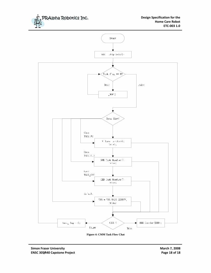
The task manager, Center Manager Module, is the interface between the nano-computer and other modules attached to the I2C BUS. It listens to both the USART port and I2C BUS, services interrupts generated by either user or other modules. As shown in Figure 4, a message sent from the nano-computer via USART will trigger the USART interrupt service routing and set the task flag; thereby a function will be called to handle the PC requests, such as resetting modules, controlling motors, sending IR control signals and setting sensors. In a similar manner, a message sent by other modules will trigger the I2C interrupt service routing and set the task flag; and then a function that handles sub-module requests will be called. In addition, CMM also has the ability to generate tasks and set the task flag itself when needed. As mentioned in the previous section, ATMega168 from ATMEL Corporation has been chosen as the microcontroller to build this module. As shown in Figure 3, pins PD0 and PD1 will be used to communicate with the nano-computer via USART protocol; and pins PC5 and PC4 will be used to communicate with other modules via I2C protocol. The pin PC6 of all the microcontrollers will be used to connect the I/O pins of CMM so that these MCUs can be reset in situation of program error or hang that cannot be fixed by the watchdog timer.
Design Specification for the Home Care Robot
ETC‐003 1.0
Simon Fraser University ENSC 305/440 Capstone Project
March 7, 2008Page 18 of 18
PPRRAAllpphhaa RRoobboottiiccss IInncc.. PPRRAAllpphhaa RRoobboottiiccss IInncc..
Figure 4: CMM Task Flow Chat

Design Specification for the Home Care Robot
ETC‐003 1.0
Simon Fraser University ENSC 305/440 Capstone Project
March 7, 2008Page 19 of 19
PPRRAAllpphhaa RRoobboottiiccss IInncc.. PPRRAAllpphhaa RRoobboottiiccss IInncc..
5 Sensor Control Module
Our product, iBonni, is able to monitor several aspects of the home situation through Sensor Control Module. The SCM can periodically collect data from sensors, store them into memory and alarm users if the sensor status is abnormal. Sensor system contains the SCM and several sensors such as temperature sensor, block sensor, fire sensor, gas sensor, flood sensor, etc. However, for propose of project demonstration, only temperature sensor and path block sensor will be included in the current development phase. The block diagram of sensor system is showed below: Store sensor status
into memory
Figure 5: Sensor System Block Diagram
As shown in Figure 6, SCM frequently checks if the temperature sensor or block sensor flag has been set in the I2C interrupt service routing. If any of these sensors are required to be monitored by the user, SCM will read the real-time status from the sensors and store them into I2C data array for later reporting to CMM. In addition, if sensors detect situations that reach the threshold values, it can send alarm signal to users.
Sensor input
Sensor control module Report abnormal
sensor status to users

Design Specification for the Home Care Robot
ETC‐003 1.0
Simon Fraser University ENSC 305/440 Capstone Project
March 7, 2008Page 20 of 20
PPRRAAllpphhaa RRoobboottiiccss IInncc.. PPRRAAllpphhaa RRoobboottiiccss IInncc..
Figure 6: SCM Flow Chat
Design Specification for the Home Care Robot
ETC‐003 1.0
Simon Fraser University ENSC 305/440 Capstone Project
March 7, 2008Page 21 of 21
PPRRAAllpphhaa RRoobboottiiccss IInncc.. PPRRAAllpphhaa RRoobboottiiccss IInncc..
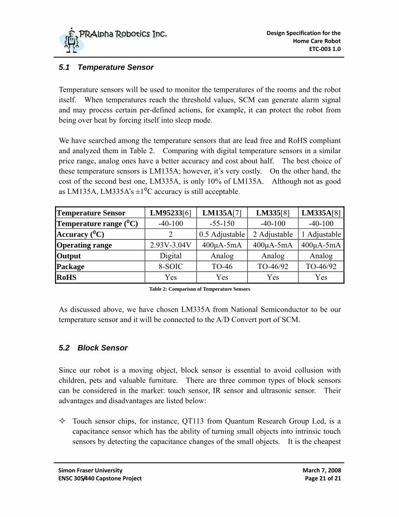
5.1 Temperature Sensor Temperature sensors will be used to monitor the temperatures of the rooms and the robot itself. When temperatures reach the threshold values, SCM can generate alarm signal and may process certain per-defined actions, for example, it can protect the robot from being over heat by forcing itself into sleep mode. We have searched among the temperature sensors that are lead free and RoHS compliant and analyzed them in Table 2. Comparing with digital temperature sensors in a similar price range, analog ones have a better accuracy and cost about half. The best choice of these temperature sensors is LM135A; however, it’s very costly. On the other hand, the cost of the second best one, LM335A, is only 10% of LM135A. Although not as good as LM135A, LM335A’s ±1⁰C accuracy is still acceptable.
Temperatu e Sensorr LM95233[6] LM135A[7] LM335[8] LM335A[8]Temperatu e range (⁰C) r -40-100 -55-150 -40-100 -40-100 Accuracy (⁰C) 2 0.5 Adjustable 2 Adjustable 1 AdjustableOperating range 2.93V-3.04V 400μA-5mA 400μA-5mA 400μA-5mAOutput Digital Analog Analog Analog Package 8-SOIC TO-46 TO-46/92 TO-46/92 RoHS Yes Yes Yes Yes
Table 2: Comparison of Temperature Sensors
As discussed above, we have chosen LM335A from National Semiconductor to be our temperature sensor and it will be connected to the A/D Convert port of SCM.
5.2 Block Sensor Since our robot is a moving object, block sensor is essential to avoid collusion with children, pets and valuable furniture. There are three common types of block sensors can be considered in the market: touch sensor, IR sensor and ultrasonic sensor. Their advantages and disadvantages are listed below:
Touch sensor chips, for instance, QT113 from Quantum Research Group Led, is a capacitance sensor which has the ability of turning small objects into intrinsic touch sensors by detecting the capacitance changes of the small objects. It is the cheapest
Design Specification for the Home Care Robot
ETC‐003 1.0
Simon Fraser University ENSC 305/440 Capstone Project
March 7, 2008Page 22 of 22
PPRRAAllpphhaa RRoobboottiiccss IInncc.. PPRRAAllpphhaa RRoobboottiiccss IInncc..
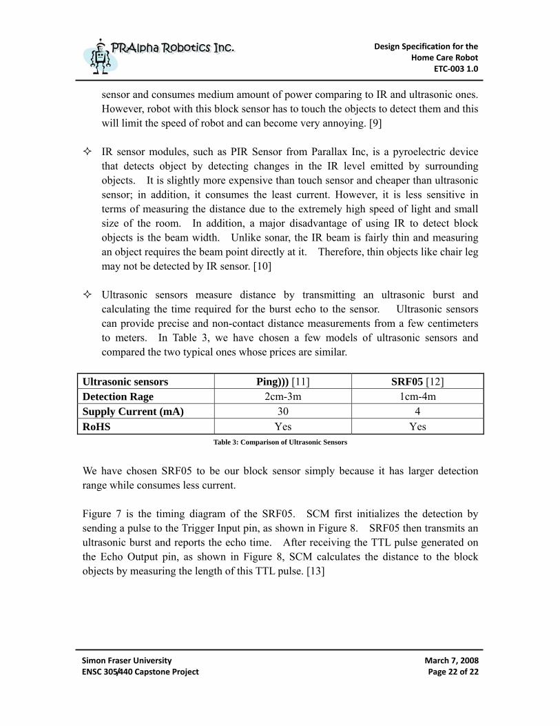
sensor and consumes medium amount of power comparing to IR and ultrasonic ones. However, robot with this block sensor has to touch the objects to detect them and this will limit the speed of robot and can become very annoying. [9]
IR sensor modules, such as PIR Sensor from Parallax Inc, is a pyroelectric device
that detects object by detecting changes in the IR level emitted by surrounding objects. It is slightly more expensive than touch sensor and cheaper than ultrasonic sensor; in addition, it consumes the least current. However, it is less sensitive in terms of measuring the distance due to the extremely high speed of light and small size of the room. In addition, a major disadvantage of using IR to detect block objects is the beam width. Unlike sonar, the IR beam is fairly thin and measuring an object requires the beam point directly at it. Therefore, thin objects like chair leg may not be detected by IR sensor. [10]
Ultrasonic sensors measure distance by transmitting an ultrasonic burst and calculating the time required for the burst echo to the sensor. Ultrasonic sensors can provide precise and non-contact distance measurements from a few centimeters to meters. In Table 3, we have chosen a few models of ultrasonic sensors and compared the two typical ones whose prices are similar.
Ultrasonic sensors Ping))) [11] SRF05 [12] Detection Rage 2cm-3m 1cm-4m Supply Current (mA) 30 4 RoHS Yes Yes
Table 3: Comparison of Ultrasonic Sensors
We have chosen SRF05 to be our block sensor simply because it has larger detection range while consumes less current. Figure 7 is the timing diagram of the SRF05. SCM first initializes the detection by sending a pulse to the Trigger Input pin, as shown in Figure 8. SRF05 then transmits an ultrasonic burst and reports the echo time. After receiving the TTL pulse generated on the Echo Output pin, as shown in Figure 8, SCM calculates the distance to the block objects by measuring the length of this TTL pulse. [13]

Design Specification for the Home Care Robot
ETC‐003 1.0
Simon Fraser University ENSC 305/440 Capstone Project
March 7, 2008Page 23 of 23
PPRRAAllpphhaa RRoobboottiiccss IInncc.. PPRRAAllpphhaa RRoobboottiiccss IInncc..
Figure 7: SRF05 Timing Diagram3
Figure 8: Pin Connection for 2-Pin Trigger/Echo Mode4
3 Figure 7 is from SRF05-Ultra-Sonic Ranger: http://www.robot-electronics.co.uk/htm/srf05tech.htm 4 Figure 8 is from SRF05-Ultra-Sonic Ranger: http://www.robot-electronics.co.uk/htm/srf05tech.htm

Design Specification for the Home Care Robot
ETC‐003 1.0
Simon Fraser University ENSC 305/440 Capstone Project
March 7, 2008Page 24 of 24
PPRRAAllpphhaa RRoobboottiiccss IInncc.. PPRRAAllpphhaa RRoobboottiiccss IInncc..
6 Action Control Module
6.1 Motor Motor is one of the most important parts of a mobile robot. In our project, powerful and accurate electrical motors are needed to drive the tank-belts. There are three general types of electrical motors for robots: DC motors, servos and stepper motors. Comparing with DC motors, servos are much easier to control but less energy efficient. They have explicit voltage requirements and are less intuitive. Stepper motors are more accurate than DC motors and have more powerful torque than servos. Because of these balanced advantages, we chose steeper motors as the actuators of our robot. Figure 9 illustrates the operation principles of a stepper motor. Stepper motors rotate as voltage is applied to their terminals, the stators. By changing the electromagnetism of the stators, the rotational speed and direction of the rotor can be controlled. So stepper motors need to be sent patterned commands to rotate. These commands are sent as high and low logic over several lines as showed in Figure 9. In that way, the motor can be turned a precise angle.
Stator (Electromagnet)
(Permanet Magnet) Rotor
Figure 9: Stepper Motor Operation5
5 Figure 9 is from http://techref.massmind.org/images/www/hobby_elec/gif/step_motor1_2.gif
Design Specification for the Home Care Robot
ETC‐003 1.0
Simon Fraser University ENSC 305/440 Capstone Project
March 7, 2008Page 25 of 25
PPRRAAllpphhaa RRoobboottiiccss IInncc.. PPRRAAllpphhaa RRoobboottiiccss IInncc..
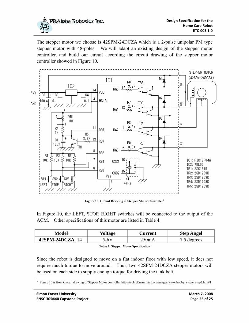
The stepper motor we choose is 42SPM-24DCZA which is a 2-pulse unipolar PM type stepper motor with 48-poles. We will adapt an existing design of the stepper motor controller, and build our circuit according the circuit drawing of the stepper motor controller showed in Figure 10.
Figure 10: Circuit Drawing of Stepper Motor Controller6
In Figure 10, the LEFT, STOP, RIGHT switches will be connected to the output of the ACM. Other specifications of this motor are listed in Table 4.
Model Voltage Current Step Angel 42SPM-24DCZA [14] 5-6V 250mA 7.5 degrees
Table 4: Stepper Motor Specification
Since the robot is designed to move on a flat indoor floor with low speed, it does not require much torque to move around. Thus, two 42SPM-24DCZA stepper motors will be used on each side to supply enough torque for driving the tank belt. 6 Figure 10 is from Circuit drawing of Stepper Motor controller:http://techref.massmind.org/images/www/hobby_elec/e_step2.htm#1

Design Specification for the Home Care Robot
ETC‐003 1.0
Simon Fraser University ENSC 305/440 Capstone Project
March 7, 2008Page 26 of 26
PPRRAAllpphhaa RRoobboottiiccss IInncc.. PPRRAAllpphhaa RRoobboottiiccss IInncc..
6.2 Action Control The core of the ACM is a microcontroller chip, Mega168. We use the same chip with other modules to save programming time. Another consideration is the communication between these chips is easy with I2C bus. The task of the ACM is simple. It receives the command words on the I2C bus, decodes the commands, and sends the commands to the stepper motor controller. Figure 11 is a task flow chart of the ACM.
Figure 11: ACM Task Flow Chart
Design Specification for the Home Care Robot
ETC‐003 1.0
Simon Fraser University ENSC 305/440 Capstone Project
March 7, 2008Page 27 of 27
PPRRAAllpphhaa RRoobboottiiccss IInncc.. PPRRAAllpphhaa RRoobboottiiccss IInncc..
7 Computer System
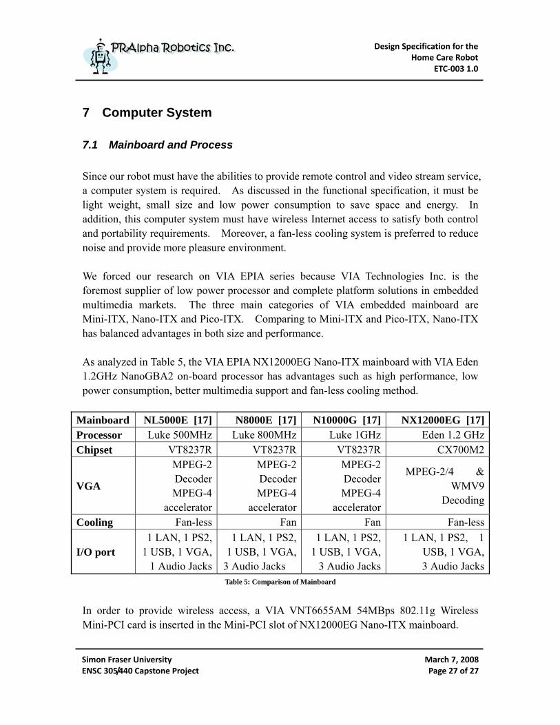
7.1 Mainboard and Process Since our robot must have the abilities to provide remote control and video stream service, a computer system is required. As discussed in the functional specification, it must be light weight, small size and low power consumption to save space and energy. In addition, this computer system must have wireless Internet access to satisfy both control and portability requirements. Moreover, a fan-less cooling system is preferred to reduce noise and provide more pleasure environment. We forced our research on VIA EPIA series because VIA Technologies Inc. is the foremost supplier of low power processor and complete platform solutions in embedded multimedia markets. The three main categories of VIA embedded mainboard are Mini-ITX, Nano-ITX and Pico-ITX. Comparing to Mini-ITX and Pico-ITX, Nano-ITX has balanced advantages in both size and performance. As analyzed in Table 5, the VIA EPIA NX12000EG Nano-ITX mainboard with VIA Eden 1.2GHz NanoGBA2 on-board processor has advantages such as high performance, low power consumption, better multimedia support and fan-less cooling method.
Mainboard NL5000E [17] N8000E [17] N10000G [17] NX12000EG [17]Processor Luke 500MHz Luke 800MHz Luke 1GHz Eden 1.2 GHzChipset VT8237R VT8237R VT8237R CX700M2
VGA
MPEG-2 Decoder MPEG-4
accelerator
MPEG-2 Decoder MPEG-4
accelerator
MPEG-2 Decoder MPEG-4
accelerator
MPEG-2/4 & WMV9
Decoding
Cooling Fan-less Fan Fan Fan-less
I/O port 1 LAN, 1 PS2,
1 USB, 1 VGA, 1 Audio Jacks
1 LAN, 1 PS2, 1 USB, 1 VGA,
3 Audio Jacks
1 LAN, 1 PS2, 1 USB, 1 VGA,
3 Audio Jacks
1 LAN, 1 PS2, 1 USB, 1 VGA, 3 Audio Jacks
Table 5: Comparison of Mainboard
In order to provide wireless access, a VIA VNT6655AM 54MBps 802.11g Wireless Mini-PCI card is inserted in the Mini-PCI slot of NX12000EG Nano-ITX mainboard.

Design Specification for the Home Care Robot
ETC‐003 1.0
Simon Fraser University ENSC 305/440 Capstone Project
March 7, 2008Page 28 of 28
PPRRAAllpphhaa RRoobboottiiccss IInncc.. PPRRAAllpphhaa RRoobboottiiccss IInncc..
In the development stage, a 2.5” notebook hard drive will be used to provide high access speed and easy system installation. In the actual product, the hard drive will be substituted by an EDC 2000+ 1GB 40pin embedded disk card to save power consumption and reduce heat and noise. In addition, since this disk card is a flash memory module and does not have moving parts, it has much better ability against vibration. Embedded version of Linux is selected as the operating system on the nano-compute due to its free licensing, excellent flexibility, high performance and outstanding reliability. We have chosen iMedia over three hundred Linux distributions because it is special made for our VIA C7 processor and only occupies 8Mb-128Mb of space. iMedia also has many pre-built packages for multimedia applications, wireless support and web server services.
7.2 Stream Sever: VLC is selected as the stream server because it is well documented and easy to setup. In addition, designing and programming client applications to receive various video stream formats from VLC are also straight forward.
7.3 Control Daemon A control daemon program will run on the nano-computer to provide a management interface between the computer and the microcontrollers. It will send commands to and receive feedback messages from the MCUs via CMM. The daemon runs multiple threads on the background to increase the efficiency. A thread waits for commands from the GUI and transfers them to CMM once the connection is established. Other threads are created when messages are received from CMM.
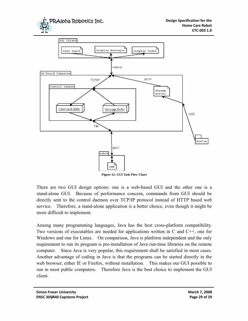
7.4 User Interface As shown in Figure 12, an overview of the GUI task flow chart, GUI receives and displays feedback messages from robot’s control daemon to remote user as well as accepts and transmits commands from user to the daemon via Internet
Design Specification for the Home Care Robot
ETC‐003 1.0
Simon Fraser University ENSC 305/440 Capstone Project
March 7, 2008Page 29 of 29
PPRRAAllpphhaa RRoobboottiiccss IInncc.. PPRRAAllpphhaa RRoobboottiiccss IInncc..
Figure 12: GUI Task Flow Chart
There are two GUI design options: one is a web-based GUI and the other one is a stand-alone GUI. Because of performance concern, commands from GUI should be directly sent to the control daemon over TCP/IP protocol instead of HTTP based web service. Therefore, a stand-alone application is a better choice, even though it might be more difficult to implement. Among many programming languages, Java has the best cross-platform compatibility. Two versions of executables are needed for applications written in C and C++, one for Windows and one for Linux. On comparison, Java is platform independent and the only requirement to run its program is pre-installation of Java run-time libraries on the remote computer. Since Java is very popular, this requirement shall be satisfied in most cases. Another advantage of coding in Java is that the programs can be started directly in the web browser, either IE or Firefox, without installation. This makes our GUI possible to run in most public computers. Therefore Java is the best choice to implement the GUI client.
Design Specification for the Home Care Robot
ETC‐003 1.0
Simon Fraser University ENSC 305/440 Capstone Project
March 7, 2008Page 30 of 30
PPRRAAllpphhaa RRoobboottiiccss IInncc.. PPRRAAllpphhaa RRoobboottiiccss IInncc..
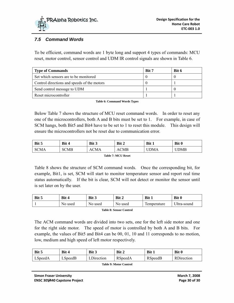
7.5 Command Words To be efficient, command words are 1 byte long and support 4 types of commands: MCU reset, motor control, sensor control and UDM IR control signals are shown in Table 6. Type of Commands Bit 7 Bit 6 Set which sensors are to be monitored 0 0 Control directions and speeds of the motors 0 1 Send control message to UDM 1 0 Reset microcontroller 1 1
Table 6: Command Words Types
Below Table 7 shows the structure of MCU reset command words. In order to reset any one of the microcontrollers, both A and B bits must be set to 1. For example, in case of SCM hangs, both Bit5 and Bit4 have to be set to 1 to reset this module. This design will ensure the microcontrollers not be reset due to communication error. Bit 5 Bit 4 Bit 3 Bit 2 Bit 1 Bit 0 SCMA SCMB ACMA ACMB UDMA UDMB
Table 7: MCU Reset
Table 8 shows the structure of SCM command words. Once the corresponding bit, for example, Bit1, is set, SCM will start to monitor temperature sensor and report real time status automatically. If the bit is clear, SCM will not detect or monitor the sensor until is set later on by the user. Bit 5 Bit 4 Bit 3 Bit 2 Bit 1 Bit 0 1 No used No used No used Temperature Ultra-sound
Table 8: Sensor Control
The ACM command words are divided into two sets, one for the left side motor and one for the right side motor. The speed of motor is controlled by both A and B bits. For example, the values of Bit5 and Bit4 can be 00, 01, 10 and 11 corresponds to no motion, low, medium and high speed of left motor respectively.
Bit 5 Bit 4 Bit 3 Bit 2 Bit 1 Bit 0 LSpeedA LSpeedB LDirection RSpeedA RSpeedB RDirection
Table 9: Motor Control
Design Specification for the Home Care Robot
ETC‐003 1.0
Simon Fraser University ENSC 305/440 Capstone Project
March 7, 2008Page 31 of 31
PPRRAAllpphhaa RRoobboottiiccss IInncc.. PPRRAAllpphhaa RRoobboottiiccss IInncc..
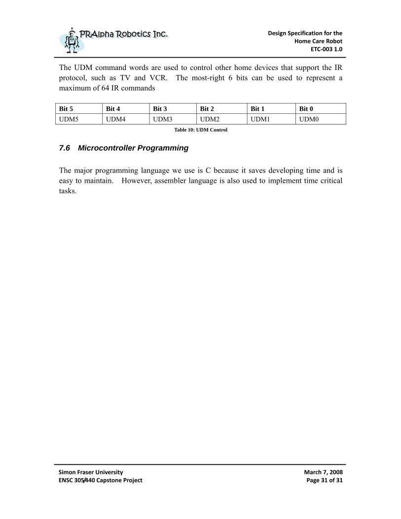
The UDM command words are used to control other home devices that support the IR protocol, such as TV and VCR. The most-right 6 bits can be used to represent a maximum of 64 IR commands Bit 5 Bit 4 Bit 3 Bit 2 Bit 1 Bit 0 UDM5 UDM4 UDM3 UDM2 UDM1 UDM0
Table 10: UDM Control
7.6 Microcontroller Programming The major programming language we use is C because it saves developing time and is easy to maintain. However, assembler language is also used to implement time critical tasks.

Design Specification for the Home Care Robot
ETC‐003 1.0
Simon Fraser University ENSC 305/440 Capstone Project
March 7, 2008Page 32 of 32
PPRRAAllpphhaa RRoobboottiiccss IInncc.. PPRRAAllpphhaa RRoobboottiiccss IInncc..
8 User Defined Module
The User Defined Module, UDM, gives the user ability of controlling other devices that supports IR protocol at home. Acting like a universal IR remote controller, UDM translates the command messages inputted by user and transmits them via Infrared protocol. UDM will use the 64 Bytes of EEPROM space to store the pre-defined IR control codes such as SONY TV, VCR and etc; and user will have freedom of adding or deleting user-defined codes. As shown in Figure 13, when a button on a general remote is pressed, its IR LED will flash at 38.5 kHz to broadcast a series of beam bursts. The sequence of beam bursts is produced by controlling the brief amounts of the IR LED flash time.
Figure 13: Handheld Remote Infrared Messages7
A short pause, called resting time, is inserted between messages to distinguish them from others.
Figure 14: Resting Time between Two IR Messages8
7 Figure 13 is from IR Remote for the Boe-Bot: http://parallax.com/Portals/0/Downloads/docs/prod/sic/WebIR-%20v1.1.pdf

Design Specification for the Home Care Robot
ETC‐003 1.0
Simon Fraser University ENSC 305/440 Capstone Project
March 7, 2008Page 33 of 33
PPRRAAllpphhaa RRoobboottiiccss IInncc.. PPRRAAllpphhaa RRoobboottiiccss IInncc..
An IR code that tells a SONY TV the pressing of button “3” is shown in Figure 15. To send a control code to a SONY TV, a burst lasts 2.4ms has to be transmitted first to indicate that a code is about to start. Then, messages that consist of a sequence of 1.2ms (binary 1) and 0.6ms (binary 0) are broadcasted. Again, a resting time of 0.6ms is inserted between each message.
Figure 15: IR Message Timing Diagram9
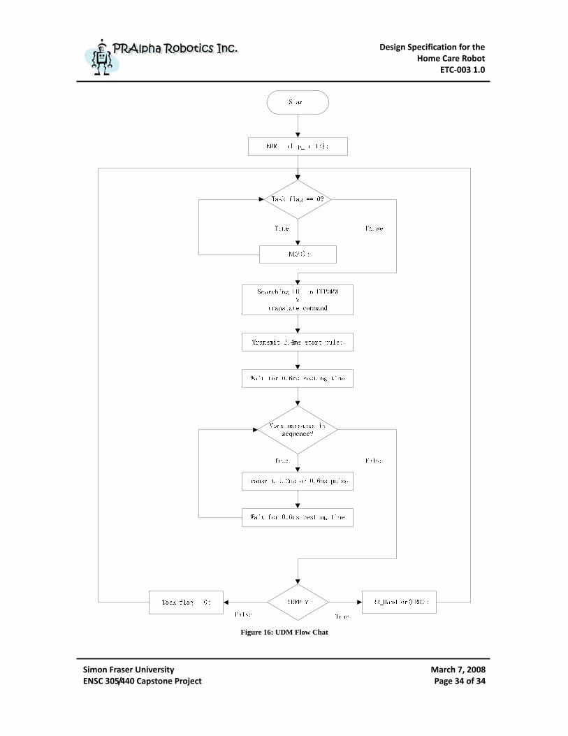
As discussed above, the goal of UDM is to send user’s commands by following the below steps: 1. Receive commands on the I2C BUS sent by user from nano-computer via CMM. 2. Translate commands to IR standard codes by using the pre-defined LUT in
EEPROM. 3. Transmit a 2.4ms start pulse to indicate the beginning of IR transmission. 4. Transmit a data pulses to indicate either a binary 1 or 0. 5. Wait during the resting time. 6. Repeat step 4 and 5 until or messages are sent in sequence. 7. Wait until the next requested command. The Output Compare Channel of ATMega168 will be used to generate the 38.5 kHz bursts and the flow chart of UDM is shown in Figure 16. Again, the task flag and command data are set in the I2C interrupt service routing.
8 Figure 14 is from IR Remote for the Boe-Bot: http://parallax.com/Portals/0/Downloads/docs/prod/sic/WebIR-%20v1.1.pdf 9 Figure 15 is from IR Remote for the Boe-Bot: http://parallax.com/Portals/0/Downloads/docs/prod/sic/WebIR-%20v1.1.pdf
Design Specification for the Home Care Robot
ETC‐003 1.0
Simon Fraser University ENSC 305/440 Capstone Project
March 7, 2008Page 34 of 34
PPRRAAllpphhaa RRoobboottiiccss IInncc.. PPRRAAllpphhaa RRoobboottiiccss IInncc..
Figure 16: UDM Flow Chat
Design Specification for the Home Care Robot
ETC‐003 1.0
Simon Fraser University ENSC 305/440 Capstone Project
March 7, 2008Page 35 of 35
PPRRAAllpphhaa RRoobboottiiccss IInncc.. PPRRAAllpphhaa RRoobboottiiccss IInncc..
9 BUS
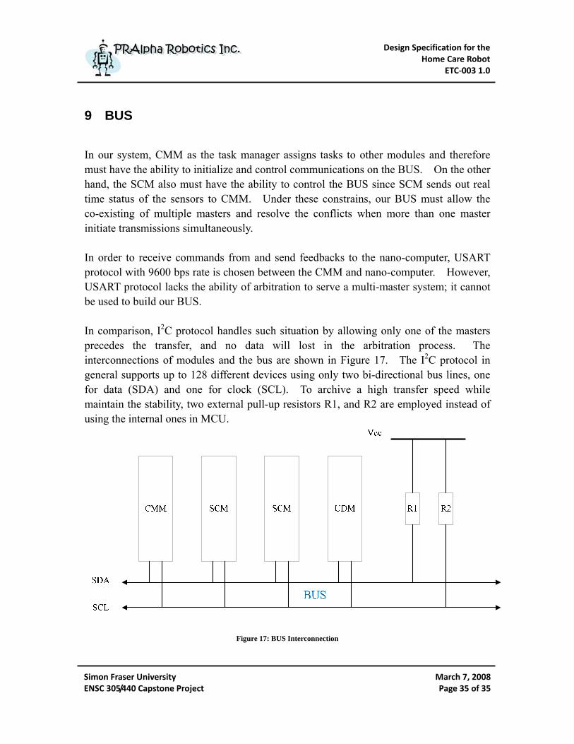
In our system, CMM as the task manager assigns tasks to other modules and therefore must have the ability to initialize and control communications on the BUS. On the other hand, the SCM also must have the ability to control the BUS since SCM sends out real time status of the sensors to CMM. Under these constrains, our BUS must allow the co-existing of multiple masters and resolve the conflicts when more than one master initiate transmissions simultaneously. In order to receive commands from and send feedbacks to the nano-computer, USART protocol with 9600 bps rate is chosen between the CMM and nano-computer. However, USART protocol lacks the ability of arbitration to serve a multi-master system; it cannot be used to build our BUS. In comparison, I2C protocol handles such situation by allowing only one of the masters precedes the transfer, and no data will lost in the arbitration process. The interconnections of modules and the bus are shown in Figure 17. The I2C protocol in general supports up to 128 different devices using only two bi-directional bus lines, one for data (SDA) and one for clock (SCL). To archive a high transfer speed while maintain the stability, two external pull-up resistors R1, and R2 are employed instead of using the internal ones in MCU.
Figure 17: BUS Interconnection

Design Specification for the Home Care Robot
ETC‐003 1.0
Simon Fraser University ENSC 305/440 Capstone Project
March 7, 2008Page 36 of 36
PPRRAAllpphhaa RRoobboottiiccss IInncc..
PPRRAAllpphhaa RRoobboottiiccss IInncc..
Figure 18 show how I2C protocol handles a multiple master system by employing the pull up resistors. The main issue to be considered in our multi-master system is that the algorithm shall only allow one master to complete the transmission; and other masters shall cease transmission and put themselves into the Salve mode to check whether they are being addressed by the winning master. In addition, the data being transmit on the bus must not be corrupted. As shown in Figure 18, both master A and B send START signals to initialize the transmissions. Having the pull up resistors, the bus line is wired-ANDing. Therefore, at the timeline marked in figure, SDA from master A is high but SDA from master B is low. In this situation, the SDA line becomes low and master A loses arbitration.
Figure 18: Arbitration between two masters10
10 Figure 18 is from ATmega48/88/168: http://atmel.com/dyn/resources/prod_documents/doc2545.pdf
Design Specification for the Home Care Robot
ETC‐003 1.0
Simon Fraser University ENSC 305/440 Capstone Project
March 7, 2008Page 37 of 37
PPRRAAllpphhaa RRoobboottiiccss IInncc.. PPRRAAllpphhaa RRoobboottiiccss IInncc..
10 Power Module
The robot must have enough power to operate continuously for a certain length of time, at least 2 hours. In addition, the robot must also have a good portability. Therefore, robot’s power must be stored into high capacity and fast charge batteries instead of using wall-plug. In order to provide stable and clean power to the control units, we decided to employ two separate batteries sets, one for the nano-computer and microcontrollers, and one for the motors. The most common battery categories are alkaline, lead acid, NiCad, NiMH, lithium and Polymer Li-Ion. After researching these various kinds of batteries, we have chosen Polymer Li-Ion to be our power as analyzed below.
Alkaline batteries are the most common, easiest to get and cheapest but they have low power capacities, are heavy and only supply large amounts of current in short time periods. The cost of constantly replacing the batteries will eventually accumulate to a significant expense.
Lead-acid batteries are one of the most widely used type battery today because they are cheap and available off the shelf. However, being very large and heavy, they cannot be used in our application. In addition, lead-acid batteries must always be kept charged and do not have the high discharge rate. They only apply for larger low performance type of robots.
NiMH batteries were widely used in older cell phones because they can be recharged many times without any memory effect and they have good current output and highest energy capacity. Due to the very long recharging time (around 10 hours) and high self-discharging time, unfortunately, they do not fit into our project.
NiCad batteries have many advantages such fast charging time (1-2 hours), more affordable than NiMH and in addition, they also have the highest current output. However, they store less and less energy after each recharge due to the memory effect; unless they are being full discharged before each recharge. In addition, NiCad batteries contain toxic cadmium martial that have to be stored and disposed properly.
Design Specification for the Home Care Robot
ETC‐003 1.0
Simon Fraser University ENSC 305/440 Capstone Project
March 7, 2008Page 38 of 38
PPRRAAllpphhaa RRoobboottiiccss IInncc.. PPRRAAllpphhaa RRoobboottiiccss IInncc..
Lithium (Li-Ion) batteries are new standard for portable power. They have almost all the advantages we have mentioned above. For instance, they have the same high energy capacity as NiMH batteries and similar power output rate of NiCad ones, with about 20-35% less in weight. They also have zero memory effect that makes them rechargeable whenever. In addition, Li-Ion batteries are made out of totally non-toxic material, making them safe for both store and dispose. The safety issue which has to be considered is that lithium reacts with water acutely and therefore fire extinguishers shall not be used on lithium battery fires.
Polymer Li-Ion batteries are very similar to Li-Ions, except they can be smaller in size and have extremely high current output. For example, our polymer Li-Ion batteries have a max discharging rate of 16000mAh, which will provide enough energy for the robot to function more than 2 hours continuously. [16]
Design Specification for the Home Care Robot
ETC‐003 1.0
Simon Fraser University ENSC 305/440 Capstone Project
March 7, 2008Page 39 of 39
PPRRAAllpphhaa RRoobboottiiccss IInncc.. PPRRAAllpphhaa RRoobboottiiccss IInncc..
11 Chassis
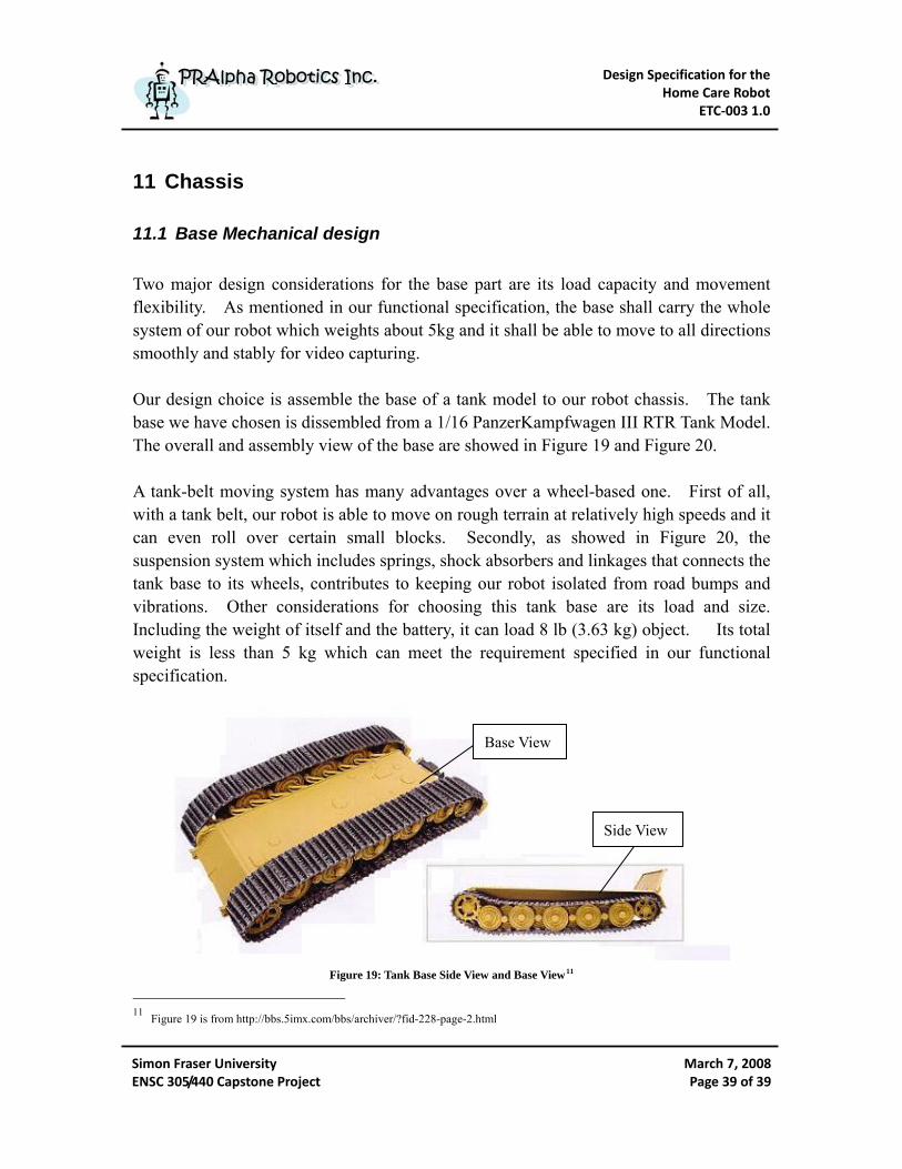
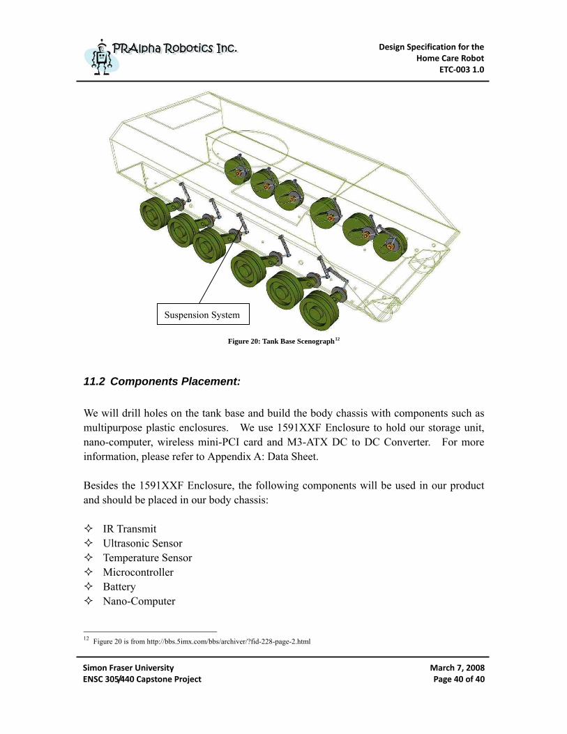
11.1 Base Mechanical design Two major design considerations for the base part are its load capacity and movement flexibility. As mentioned in our functional specification, the base shall carry the whole system of our robot which weights about 5kg and it shall be able to move to all directions smoothly and stably for video capturing. Our design choice is assemble the base of a tank model to our robot chassis. The tank base we have chosen is dissembled from a 1/16 PanzerKampfwagen III RTR Tank Model. The overall and assembly view of the base are showed in Figure 19 and Figure 20. A tank-belt moving system has many advantages over a wheel-based one. First of all, with a tank belt, our robot is able to move on rough terrain at relatively high speeds and it can even roll over certain small blocks. Secondly, as showed in Figure 20, the suspension system which includes springs, shock absorbers and linkages that connects the tank base to its wheels, contributes to keeping our robot isolated from road bumps and vibrations. Other considerations for choosing this tank base are its load and size. Including the weight of itself and the battery, it can load 8 lb (3.63 kg) object. Its total weight is less than 5 kg which can meet the requirement specified in our functional specification.
Base View
Side View
Figure 19: Tank Base Side View and Base View11 11 Figure 19 is from http://bbs.5imx.com/bbs/archiver/?fid-228-page-2.html
Design Specification for the Home Care Robot
ETC‐003 1.0
Simon Fraser University ENSC 305/440 Capstone Project
March 7, 2008Page 40 of 40
PPRRAAllpphhaa RRoobboottiiccss IInncc.. PPRRAAllpphhaa RRoobboottiiccss IInncc..
Suspension System
Figure 20: Tank Base Scenograph12
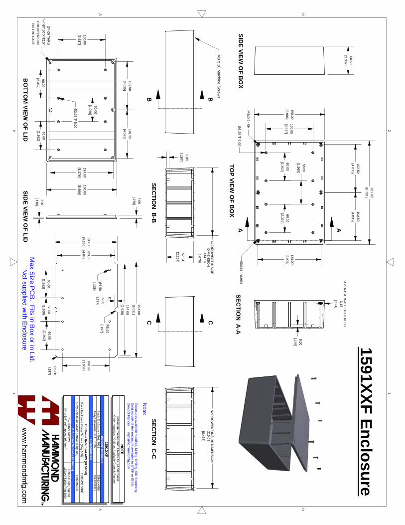
11.2 Components Placement: We will drill holes on the tank base and build the body chassis with components such as multipurpose plastic enclosures. We use 1591XXF Enclosure to hold our storage unit, nano-computer, wireless mini-PCI card and M3-ATX DC to DC Converter. For more information, please refer to Appendix A: Data Sheet. Besides the 1591XXF Enclosure, the following components will be used in our product and should be placed in our body chassis:
IR Transmit Ultrasonic Sensor Temperature Sensor Microcontroller Battery Nano-Computer
12 Figure 20 is from http://bbs.5imx.com/bbs/archiver/?fid-228-page-2.html
Design Specification for the Home Care Robot
ETC‐003 1.0
Simon Fraser University ENSC 305/440 Capstone Project
March 7, 2008Page 41 of 41
PPRRAAllpphhaa RRoobboottiiccss IInncc.. PPRRAAllpphhaa RRoobboottiiccss IInncc..
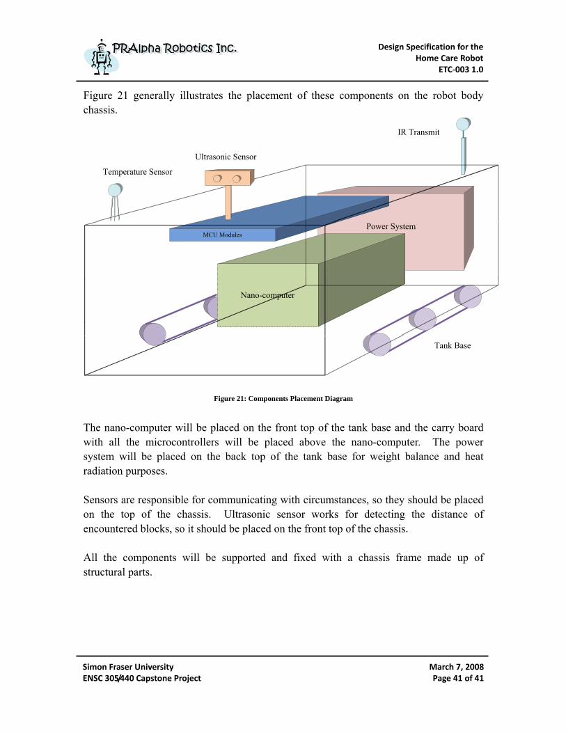
Figure 21 generally illustrates the placement of these components on the robot body chassis.
Power SystemMCU Modules
Nano-computer
Ultrasonic Sensor
Tank Base
IR Transmit
Temperature Sensor
Figure 21: Components Placement Diagram
The nano-computer will be placed on the front top of the tank base and the carry board with all the microcontrollers will be placed above the nano-computer. The power system will be placed on the back top of the tank base for weight balance and heat radiation purposes. Sensors are responsible for communicating with circumstances, so they should be placed on the top of the chassis. Ultrasonic sensor works for detecting the distance of encountered blocks, so it should be placed on the front top of the chassis. All the components will be supported and fixed with a chassis frame made up of structural parts.
Design Specification for the Home Care Robot
ETC‐003 1.0
Simon Fraser University ENSC 305/440 Capstone Project
March 7, 2008Page 42 of 42
PPRRAAllpphhaa RRoobboottiiccss IInncc.. PPRRAAllpphhaa RRoobboottiiccss IInncc..
12 System Test Plan
Each module of the robot will be tested individually first during the development phase. After finishing module unit testing, relative modules will be integrated for testing prospective functionalities. Finally, we will integrate the overall system and perform a comprehensive and rehearsal testing which is designed for demonstration.
12.1 Module Unit Test Plan
12.1.1 Center Manager Module We will verify the CMM is able to listen and handle the requests from PC via USART as well as the feedbacks from other modules attached on the I2C BUS. We will verify the CMM is able to assign tasks between modules and reset modules if necessary.
12.1.2 Action Control Module We will verify the ACM is able to control the rotation of stepper motor responding to the instructions sent from CMM via I2C.
12.1.3 Sensor Control Module We will verify the SCM is able to properly capture signals from temperature sensor and ultrasonic sensor then work out useful data. We will verify the SCM is able to store these data into memory and report to CMM if requested. We will verify the SCM is able to analysis the data and automatically report to CMM if they are abnormal.
12.1.4 User Defined Module We will verify the UDM is able to receive user’s different command messages from CMM via I2C, translate them and send corresponding IR signals.
12.1.5 Power Module We will verify the maximum and minimum cut-off voltages and currents of the power module. We will verify the capacity of the battery and the fully charging and discharging time. The testing results should meet the specified requirements listed in

Design Specification for the Home Care Robot
ETC‐003 1.0
Simon Fraser University ENSC 305/440 Capstone Project
March 7, 2008Page 43 of 43
PPRRAAllpphhaa RRoobboottiiccss IInncc.. PPRRAAllpphhaa RRoobboottiiccss IInncc..
our functional specification. The power module’s weight, size, safety and environment considerations will also be tested.
12.2 Functionality Test Plan For functionality testing, relative modules will be integrated. After ensuring each module works properly, the following cases for specified functionalities will be tested in a controlled environment.
12.2.1 Test Case 1: Mobility User Input: The user clicks the moving forward and backward, turn left and right,
accelerate and decelerate buttons on the GUI client screen. Conditions: Place the fully charged home care robot, iBonni, on a flat floor. Expected Result: iBonni moves towards the user requested directions smoothly and
stably.
12.2.2 Test Case 2: Temperature Sensory User Input: The user clicks the temperature request button on the GUI client
screen. Conditions: Place the fully charged iBonni on a flat floor and change the
temperature around the temperature sensor. Expected Result: iBonni reports correct temperatures (±1oC) to user and automatically
alarm user if the temperature is abnormal.
12.2.3 Test Case 3: Block Sensory User Input: The user clicks the movement control buttons on the GUI client
screen. Conditions: Place the fully charged iBonni on the flat ground with various blocks.Expected Result: iBonni reports the distance to the encountered block within 4m to
user and automatically stops in front of the block
Design Specification for the Home Care Robot
ETC‐003 1.0
Simon Fraser University ENSC 305/440 Capstone Project
March 7, 2008Page 44 of 44
PPRRAAllpphhaa RRoobboottiiccss IInncc.. PPRRAAllpphhaa RRoobboottiiccss IInncc..
12.2.4 Test Case 4: User Control User Input: The User clicks the user defined buttons on the GUI client screen. Conditions: Pre-define the UDM and place the fully charged iBonni on ground
facing to the remotely controlled device. Expected Result: The device is remotely controlled by user via iBonni.
12.3 Overall System Test Plan After successfully finishing the above functionality test plans, the whole robot system should be completely integrated and overall system test plans will be carried on. After complete the overall system integration, all the modules should work properly in a real environment. For overall system testing, the above test cases will be repeated and combined. Based on the requirements listed in the functional specification, various user inputs and environment situations will be checked. The overall robot size, weight, maximum allowable load and power consumption will be tested to ensure they meet the requirements. The testing will be complete when the main functionalities outlined in the functional specification for the proof-of-concept device have been tested and achieved.

Design Specification for the Home Care Robot
ETC‐003 1.0
Simon Fraser University ENSC 305/440 Capstone Project
March 7, 2008Page 45 of 45
PPRRAAllpphhaa RRoobboottiiccss IInncc.. PPRRAAllpphhaa RRoobboottiiccss IInncc..
13 Conclusion
The design specification detailed outlines all of our design choices and the justifications to meet most of the requirements specified in our functional specification. The home care robot, iBonni, will be developed based upon the design considerations discussed in this document which also helps the project team to measure the development progress and performance better. The test plan included in this document will also help to ensure all the required functionalities are implemented With the design specifications listed in this document, a fully functional prototype of the home care robot will be complete by the beginning of April, 2008
Design Specification for the Home Care Robot
ETC‐003 1.0
Simon Fraser University ENSC 305/440 Capstone Project
March 7, 2008Page 46 of 46
PPRRAAllpphhaa RRoobboottiiccss IInncc.. PPRRAAllpphhaa RRoobboottiiccss IInncc..
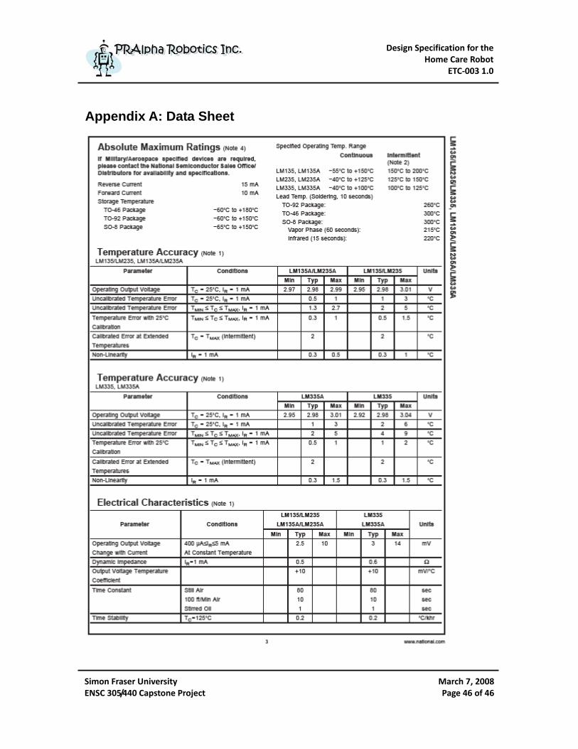
Appendix A: Data Sheet
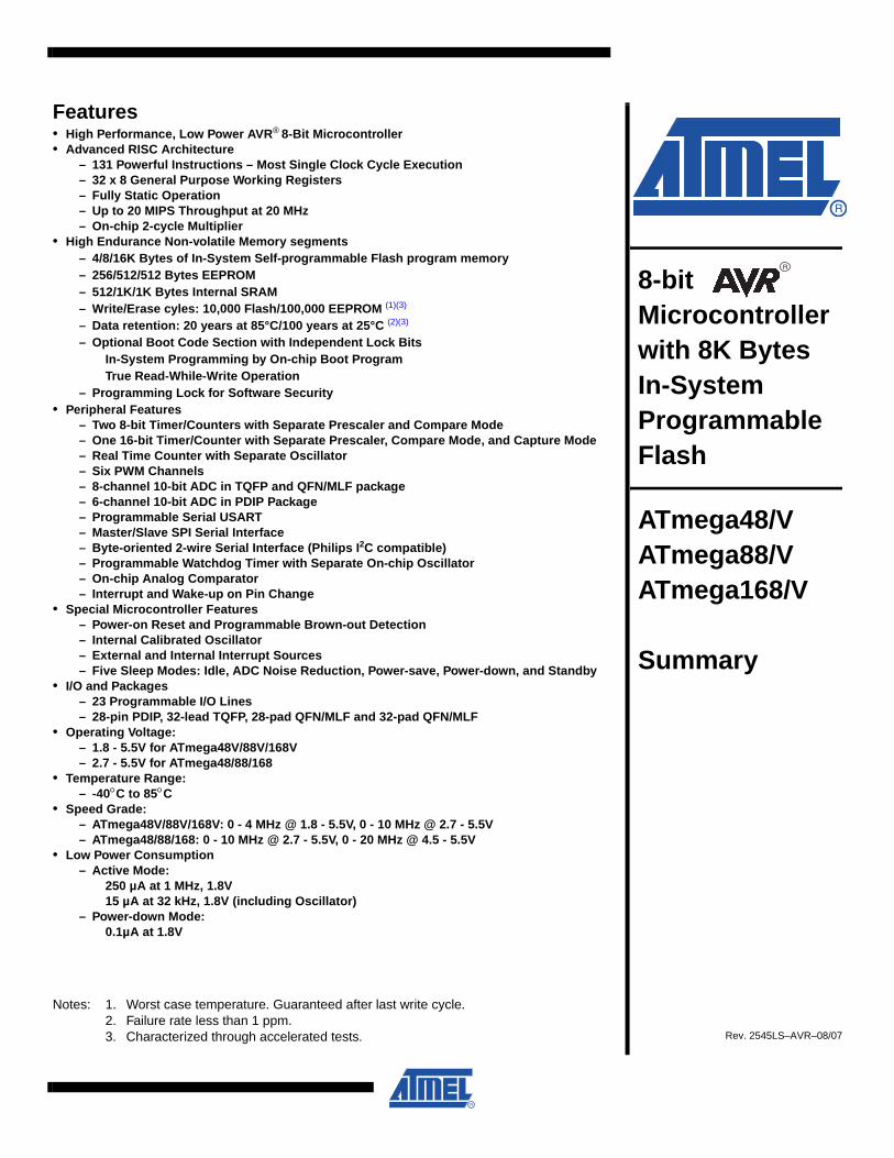
Features• High Performance, Low Power AVR® 8-Bit Microcontroller• Advanced RISC Architecture
– 131 Powerful Instructions – Most Single Clock Cycle Execution– 32 x 8 General Purpose Working Registers– Fully Static Operation– Up to 20 MIPS Throughput at 20 MHz– On-chip 2-cycle Multiplier
• High Endurance Non-volatile Memory segments– 4/8/16K Bytes of In-System Self-programmable Flash program memory– 256/512/512 Bytes EEPROM– 512/1K/1K Bytes Internal SRAM– Write/Erase cyles: 10,000 Flash/100,000 EEPROM (1)(3)
– Data retention: 20 years at 85°C/100 years at 25°C (2)(3)
– Optional Boot Code Section with Independent Lock BitsIn-System Programming by On-chip Boot ProgramTrue Read-While-Write Operation
– Programming Lock for Software Security• Peripheral Features
– Two 8-bit Timer/Counters with Separate Prescaler and Compare Mode– One 16-bit Timer/Counter with Separate Prescaler, Compare Mode, and Capture Mode– Real Time Counter with Separate Oscillator– Six PWM Channels– 8-channel 10-bit ADC in TQFP and QFN/MLF package– 6-channel 10-bit ADC in PDIP Package– Programmable Serial USART– Master/Slave SPI Serial Interface– Byte-oriented 2-wire Serial Interface (Philips I2C compatible)– Programmable Watchdog Timer with Separate On-chip Oscillator– On-chip Analog Comparator– Interrupt and Wake-up on Pin Change
• Special Microcontroller Features– Power-on Reset and Programmable Brown-out Detection– Internal Calibrated Oscillator– External and Internal Interrupt Sources– Five Sleep Modes: Idle, ADC Noise Reduction, Power-save, Power-down, and Standby
• I/O and Packages– 23 Programmable I/O Lines– 28-pin PDIP, 32-lead TQFP, 28-pad QFN/MLF and 32-pad QFN/MLF
• Operating Voltage:– 1.8 - 5.5V for ATmega48V/88V/168V– 2.7 - 5.5V for ATmega48/88/168
• Temperature Range:– -40°C to 85°C
• Speed Grade:– ATmega48V/88V/168V: 0 - 4 MHz @ 1.8 - 5.5V, 0 - 10 MHz @ 2.7 - 5.5V– ATmega48/88/168: 0 - 10 MHz @ 2.7 - 5.5V, 0 - 20 MHz @ 4.5 - 5.5V
• Low Power Consumption– Active Mode:
250 µA at 1 MHz, 1.8V 15 µA at 32 kHz, 1.8V (including Oscillator)
– Power-down Mode: 0.1µA at 1.8V
Notes: 1. Worst case temperature. Guaranteed after last write cycle.2. Failure rate less than 1 ppm.3. Characterized through accelerated tests.
8-bit Microcontroller with 8K Bytes In-SystemProgrammable Flash
ATmega48/VATmega88/V ATmega168/V
Summary
Rev. 2545LS–AVR–08/07

Approximate Beam Pattern Interface Ranging Distance Dimensions
19.9 mm Length 22.1 mm Width 16.4 mm Height
6 to 254 inches (6.45m)
Serial (0-5V), Analog Voltage or Pulse Width
Voltage: 5V Current: 3ma Typical.
43 mm Length 20 mm Width 17 mm Height
3cm to 3m
Positive TTL level signal, width proportional to range.
Voltage: 5V Current: 30ma Typical, 50ma Max
43 mm Length 20 mm Width 17 mm Height
1cm to 4m
Positive TTL level signal, width proportional to range.
Voltage: 5V Current: 4ma Typical
43 mm Length 20 mm Width 17 mm Height
3cm to 6m Standard I2C Bus
Voltage: 5V Current: 15ma Typical, 3ma Standby
32 mm Length 15 mm Width 10 mm Height
3cm to 6m Standard I2C Bus
Voltage: 5V Current: 15ma Typical, 3ma Standby
34 mm Length 20 mm Width 19 mm Height
10cm to 1.2m Standard I2C Bus
Voltage: 5V Current: 25ma Typical
Ultrasonic Rangefinder Comparison
Maxbotix MaxSonar-EZ1
Devantec SRF04
Devantec SRF05
Devantec SRF08
Devantec SRF10
Devantec SRF235
Power Requirements
- 1 Foot
24 mm Length 20 mm Width 12 mm Height
15cm to 6m Standard I2C Bus
Voltage: 5V Current: 4ma Typical
Devantec SRF02 Serial (0-5V)
EXPLOD
ED VIEW
OF EN
CLO
SUR
E
EXPLOD
ED VIEW
OF EN
CLO
SUR
E
TOP VIEW
OF B
OX
SIDE VIEW
OF B
OX
SEC
TION
A-A
SECTIO
N B
-B
SECTIO
N C
-C
BO
TTOM
VIEW O
F LID
SIDE VIEW
OF LID
Black E
nclosure - RAL 7011
1591XX
FBK
Gray E
nclosure - RAL 7035
1591XX
FGY
P.C
. Board S
crews
[#4 x 1/4" self-tapping (6.4mm
)]1593A
TS50 (Pkg 50)
1593ATS
100 (Pkg 100)
NO
TEE
nclosure molded from
FRA
BS
UL 94-V0 P
lastic. O
ther materials / C
olours Available C
onsult Factory
Black E
nclosure Cover S
crews (Pkg 100)
1591MS
100BK
For Flame R
etardent ABS (U
L94-V0)
P.C. B
oard Screws (All B
oxes)1591M
S100
Gray E
nclosure Cover S
crews (P
kg 100)
1591XXF1590XXF Enclosure
ACC
ESSOR
IES
11
22
AA
BB
AA
BB
CC
1591XXF Enclosure60.50
[2.382]
102.50[4.035]
102.50[4.035]
60.00[2.362]
50.00[1.969]
60.00[2.362]
221.00[8.701]
100.00[3.937]
134.00[5.276]
150.00[5.906]
M3x0.5 - 6Hn
2.25 x 5.00
5.00[.197]
3.16[.124]
AV
ER
AG
E W
ALL TH
ICK
NE
SS
144.16[5.676]
NA
RR
OW
ES
T INS
IDE
DIM
EN
SIO
N
5.00[.197]
57.34[2.257]
215.09[8.468]
NA
RR
OW
ES
T INS
IDE D
IMEN
SIO
N
60.00[2.362]
60.00[2.362]
50.00[1.969]
n4.00 TH
RU
w n
7.00 X 82.0°
CO
UN
TER
SIN
KO
N TO
P FA
CE
n2.25 x
5.00
102.50[4.035]
102.50[4.035]
134.00[5.276]
150.00[5.906]
100.00[3.937]
7.00[.276]
3.00[.118]
194.00[7.638]
204.00[8.031]
123.00[4.843]
133.00[5.236]
60.00[2.362]
60.00[2.362]
50.00[1.969]
100.00[3.937]
R5.00
[.197]n
3.50
[.138]
5.00[.197]
R5.00
[.197]
Max S
ize PC
B. Fits in B
ox or in Lid.N
ot supplied with E
nclosure
Note:
Enclosures available m
odified, Milling, D
rilling, Silk S
creening.S
olid models of this enclosure available in S
TEP
or IGE
S.
Contact Factory m
jm@
hamm
ondmfg.com
Brass Inserts
M3 x 10 M
achine Screw
s

Design Specification for the Home Care Robot
ETC‐003 1.0
Simon Fraser University ENSC 305/440 Capstone Project
March 7, 2008Page 47 of 47
PPRRAAllpphhaa RRoobboottiiccss IInncc.. PPRRAAllpphhaa RRoobboottiiccss IInncc..
References
1. PRAlpha, Inc. Functional Specification for the Home Care Robot. Burnaby : Simon Fraser University, Febrary, 2008. 2. Parallax, Inc. Basic Stamp 2p. http://www.parallax.com/. [Online] 2007. [Cited: March 3, 2008.] http://www.parallax.com/Portals/0/Downloads/docs/prod/book/bs2pCommnFeat.pdf. 3. Atmel Corporation. ATmega16 (L). http://www.atmel.com/. [Online] 2008. [Cited: March 4, 2008.] http://www.atmel.com/dyn/resources/prod_documents/doc2466.pdf. 2466P–AVR–08/07 4. —. ATmega48/88/168. http://www.atmel.com. [Online] 2008. [Cited: March 4, 2008.] http://www.atmel.com/dyn/resources/prod_documents/doc2545.pdf. 5. —. ATmega128 (L). http://www.atmel.com/. [Online] 2008. [Cited: March 4, 2008.] http://www.atmel.com/dyn/resources/prod_documents/doc2467.pdf. 6. National Semiconductor Corporation. LM95233 - Precision Temperature Sensor. http://www.national.com/. [Online] 2008. [Cited: March 5, 2008.] http://cache.national.com/ds/LM/LM95233.pdf. 7. —. LM135A - Precision Temperature Sensor. http://www.national.com/. [Online] 2007. [Cited: March 5, 2008.] http://www.national.com/ds/LM/LM135.pdf. 8. —. LM335A - Precision Temperature Sensor. http://www.national.com/. [Online] 2007. [Cited: March 5, 2008.] http://www.national.com/ds/LM/LM135.pdf. 9. Quantum Research Group Led. http://www.qprox.com/. [Online] 2004. [Cited: March 3, 2008.] http://www.qprox.com/assets/Downloadablefile/qt113_105-15457.pdf. 10. Parallax, Inc. http://www.parallax.com/. [Online] 2007. [Cited: March 3, 2008.] http://parallax.com/Portals/0/Downloads/docs/prod/audiovis/PIRSensor-V1.2.pdf.

Design Specification for the Home Care Robot
ETC‐003 1.0
Simon Fraser University ENSC 305/440 Capstone Project
March 7, 2008Page 48 of 48
PPRRAAllpphhaa RRoobboottiiccss IInncc.. PPRRAAllpphhaa RRoobboottiiccss IInncc..
11. —. www.parallax.com. [Online] 2008. [Cited: March 4, 2008.] http://parallax.com/Portals/0/Downloads/docs/prod/acc/28015-PING-v1.5.pdf. #28015. 12. RobotShop Distribution inc. SRF05 - Ultrasonic Range Finder. [Online] 2008. [Cited: March 4, 2008.] http://www.robotshop.ca/PDF/rbdev16_spec.pdf. 13. RobotShop Distribution, inc. SRF05 - Ultra-Sonic Ranger. http://www.robotshop.ca/. [Online] RobotShop Distribution, inc., 2008. [Cited: March 4, 2008.] http://www.robot-electronics.co.uk/htm/srf05tech.htm. 14. Parts explanation of Stepper Motor controller. [Online] [Cited: March 5, 2008.] http://techref.massmind.org/images/www/hobby_elec/e_step4.htm. 15. Netlink Computer Inc. nGear USB2.0 to RS-232 ( 9 Pins ) Serial Adapter W/ USB Cable. http://www.ncix.com/. [Online] Netlink Computer Inc., 2008. [Cited: March 5, 2008.] http://www.ncix.com/products/index.php?sku=17281&vpn=G%2DS402&manufacture=nGear%20Technologies%20Inc%2E. 16. Society of Robots. ROBOT BATTERIES. http://www.societyofrobots.com/. [Online] 2008. [Cited: March 5, 2008.] http://www.societyofrobots.com/batteries.shtml. 17. LogicSupply. [Online] [Cited: March 06, 2008.] http://www.logicsupply.com/categories/mainboards/nano_itx.

![(Master of Health)] }JAJO Z +00 O rrr I I ITT tx@o . Q.) O cotsph/International_Cooperation...}JAJO Z_ +00 O rrr I I ITT tx@o . Q.) O co Created Date 5/22/2013 2:39:06 PM](https://img.pdfslide.net/doc/110x75/60fe3faaafcb9b2a3a4684ce/master-of-health-jajo-z-00-o-rrr-i-i-itt-txo-q-o-co-tsphinternationalcooperation.jpg)


![RRR工法協会rrr-sys.gr.jp/tayori/RRRvol38.pdfReinforced-soil Railroad / Road structures with Rigid facing No. 38 2016.08 RRR 1. r -GPC] y r D (RRR-Nai/)J 37-4 (a) (I) -374 g-2.l](https://img.pdfslide.net/doc/110x75/5fcb823f24b79b62d247d3a5/rrrrrr-sysgrjptayori-reinforced-soil-railroad-road-structures.jpg)