Embed Size (px)
Citation preview
PPV 2013
IMAGING SERVICES
LAST REVISION DATE: JUNE 2013
ABDOMEN
*Cervical collars, casts, braces, etc. shall not be removed unless specifically requested by the referring physician.
ABDOMEN (1 image) KUB
ABDOMEN: R/O OBSTRUCTION (2 images) AP Supine Upright or Decubitus
ACUTE ABDOMEN SERIES (3 images) PA Chest AP Supine Upright or Decubitus
ABDOMEN: R/O AORTIC ANEURYSM (2 images) *Do not do a shoot through lateral. AP Supine LPO
ABDOMEN: POST COLONOSCOPY
If requisition states: pt with pain or r/o perforation, an Upright KUB should be performed first
BACLOFEN PUMP EN FACE
AP of baclofen pump, to include the entire length of wires into the thoracic/lumbar cavity Lateral of baclofen pump, to include the spine to follow the wires into the thoracic/lumbar
cavity
8
PPV 2013
IMAGING SERVICES
LAST REVISION DATE: JUNE 2013
CHEST/THORAX
*Cervical collars, casts, braces, etc. shall not be removed unless specifically requested by the referring physician.
CHEST (2 images) PA Chest Lateral
**note: when taking special views such as apical lordotic, decubitus, or obliques, consult the ordering physician if they would like a PA and Lateral chest as well IF the patient has not had them done previously. An additional order must be placed by the physician.**
RIBS UNILATERAL (4 images) AP Upper Ribs Posterior Oblique Upper Ribs AP Lower Ribs Posterior Oblique Lower Ribs
RIBS BILATERAL (6 images) AP Upper Ribs AP Lower Ribs Posterior Oblique Upper & Lower Ribs
STERNUM (3 images) RAO LAO Lateral
STERNOCLAVICULAR JOINTS (3 images) PA Projection RAO & LAO
STERNOCLAVICULAR JOINTS: R/O DISLOCATION (4 images) AP PA Projection RAO & LAO
9
PPV 2013
IMAGING SERVICES
LAST REVISION DATE: JUNE 2013
DR HERZBERG
SHOULDER: AP 30° caudal angle
Supra outlet
Supine Axillary
True AP External Rotation
AP Internal Rotation
KNEE: Standing AP
Standing Lateral
Merchant (Bilateral)
Salt Lake (Bilateral)
PELVIS/HIP: Standing Pelvis
Roll out Lateral
FOOT: Weight bearing images if possible
AP
Oblique
Lateral (if possible)
ANKLE: Weight bearing images if possible
AP
Mortise
Lateral (if possible)
10
PPV 2013
IMAGING SERVICES
LAST REVISION DATE: JUNE 2013
DR HERZKA
SHOULDER: True AP (Grashey)
Zenca
Supra Outlet
Supine Axillary
KNEE: Standing AP
Salt Lake (Bilateral – Wants to see joint space open)
Lateral
Lauren (Bilateral – Pointy sunrise)
PELVIS: Standing AP (NGS)
HIP: Frog Leg Lateral
11
PPV 2013
IMAGING SERVICES
LAST REVISION DATE: JUNE 2013
DR HUFF
KNEE: Weight bearing if possible
AP
Lateral
Merchant (Bilateral)
Salt Lake (Bilateral)
FOLLOW UP/POST-OP KNEE:
Weight bearing if possible
AP
Lateral
Sunrise (affected side only)
PELVIS/HIP: Standing Hip-Centered Pelvis
Supine AP Hip
Supine Lateral Frog Leg (if bilateral ordered – take hip images unilaterally)
12
PPV 2013
IMAGING SERVICES
LAST REVISION DATE: JUNE 2013
DR MIRZA
CLAVICLE:
WITH HARDWARE:
AP (Supine)
35° Caudal angle (Supine)
*Images should look like surgery images
WITHOUT HARDWARE:
Standard Protocol
13
PPV 2013
IMAGING SERVICES
LAST REVISION DATE: JUNE 2013
LOWER EXTREMITY
*Cervical collars, casts, braces, etc. shall not be removed unless specifically requested by the referring physician.
**In trauma cases, include both joints if possible; otherwise, include joint nearest to area of injury.
FEMUR (2 – 4 images) AP Lateral
KNEE: NON-TRAUMA (2 images) AP Lateral
KNEE: TRAUMA (2 - 3 images) AP Lateral Sunrise
INTERCONDYLAR FOSSA Camp Coventry Method
TIBIA-FIBULA (2 – images) AP Lateral
ANKLE: TRAUMA & NON-TRAUMA (3 views) AP Mortise Lateral
FOOT: TRAUMA & NON-TRAUMA (3 views) AP Medial Oblique Lateral
OS CALCIS (2 images) Axial Lateral
14
PPV 2013
TOE (3 images) AP (AP of the entire foot, with arrow pointing to the affected toe) Oblique (of affected toe only) Lateral (of affected toe only)
BONE LENGTH STUDY (1 image)
AP OF ENIRE HIP TO ANKLE (include femoral head to ankle joint)o Be sure to use aluminum filter to avoid burn out of the bottom of the legso Ruler taped to boardo Average technique 80@100
15
PPV 2013
IMAGING SERVICES
LAST REVISION DATE: JUNE 2013
SPECIAL VIEWS – LOWER
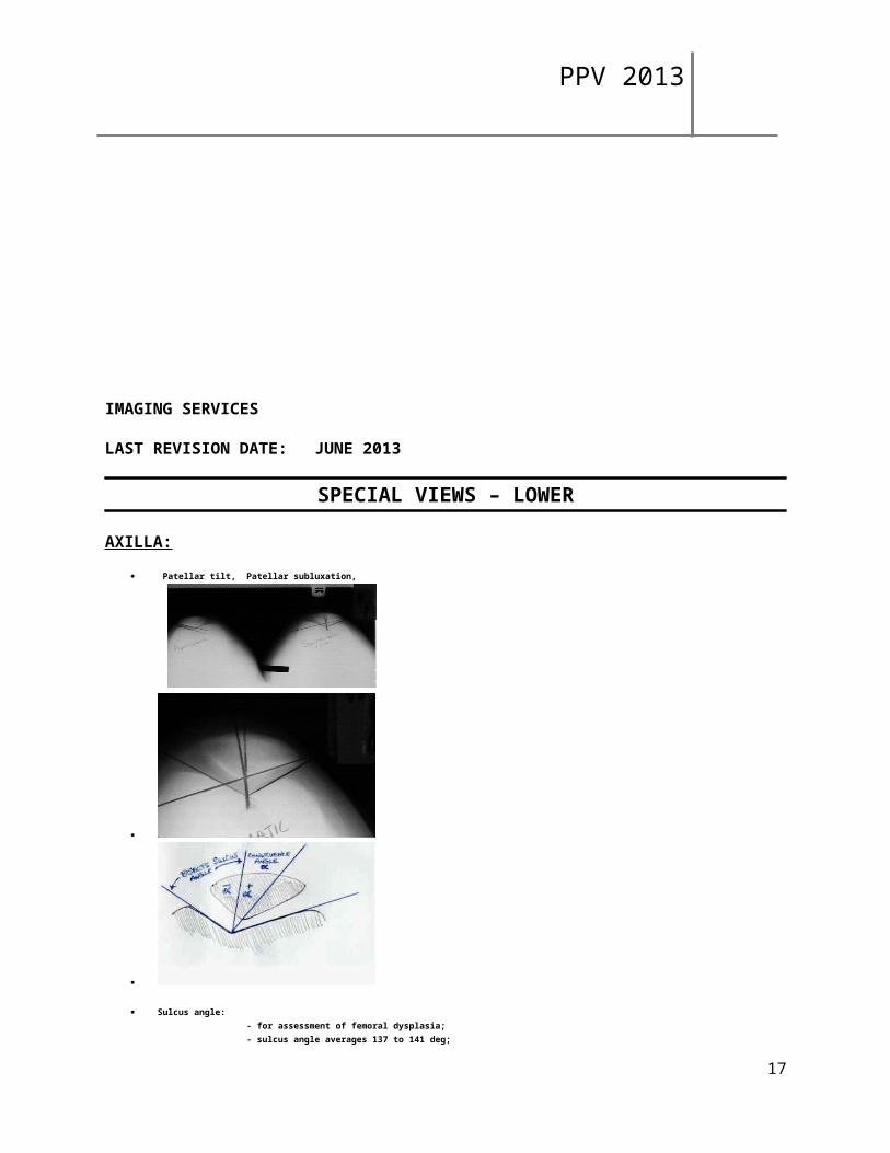
AXILLA:
Patellar tilt, Patellar subluxation,
Sulcus angle:
- for assessment of femoral dysplasia; - sulcus angle averages 137 to 141 deg; - in patients w/ subluxation, the mean sulcus angle is 147 deg, with a range of 137 to 172; - references: - Shape of the intercondylar groove normally and in recurrent dislocation of the patella: A clinical and x-ray anatomical investigation.
- Technique Pearls:
- for x-ray to be meaningful, both knees should be included at the same time for comparison; - knees should be flexed in range of 20 to 45 deg, since more flexion will generally reduce most patellofemoral abnormalities; - Merchant technique - used to evaluate subluxation; - Laurin technique: - lateral patellofemoral angle is index of tilt but not of subluxation; - patellar alignment assessed using lateral patellofemoral angle on axial views, made w/ knee in 20 deg of flexion; - angle formed by lateral patellar facet & line drawn across most prominent aspects of anterior portion of femoral trochlea should be open laterally in normal patellofemoral joint; - Stress Axilla View: - in some cases, there will be impressive differences between static and dynamic axilla knee views; - made with the knee flexed 35 deg off the end of the x-ray table; - a constant lateral pressure is exerted on to the patella in an attempt to displace the patella laterally; - comparisons should be made between the symptomatic and asymptomatic knees; - Sunrise View: - used to image a tangential view of the patella; - the patient is prone with the knee flexed 115 deg; - central beam is directed toward the patella with 15 deg cephalic tilt
16
PPV 2013
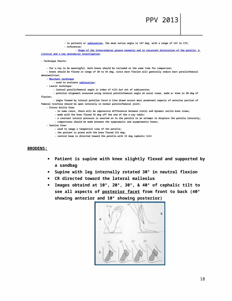
BRODENS:
Patient is supine with knee slightly flexed and supported by a sandbag Supine with leg internally rotated 30° in neutral flexion CR directed toward the lateral malleolus Images obtaind at 10°, 20°, 30°, & 40° of cephalic tilt to see all aspects of posterior
facet from front to back (40° showing anterior and 10° showing posterior)
Sub-types Lateral oblique view
o Patient is supine with inner border of foot placed on cassette and the sole inclined 45°
o Central beam directed vertically centered 1 in. below and 1 in. anterior to the tip of the lateral malleolus
Lateral oblique axial o Foot is passively everted, dorsiflexed and externally rotated 60°o Central beam centered 1 inch below tip of medial malleolus with 10
deg cephalic tilt Medial oblique axial
o Patient is supineo Foot is passively dorsiflexed, inverted, and internally rotated 60°o Broden described a similar projection with limb internally rotated 45°o Broden recommended taking four exposures with the CR andgled 40°,
30°, 20°, and 10° cephalad to see all aspects of posterior facet from front to back.
17
PPV 2013
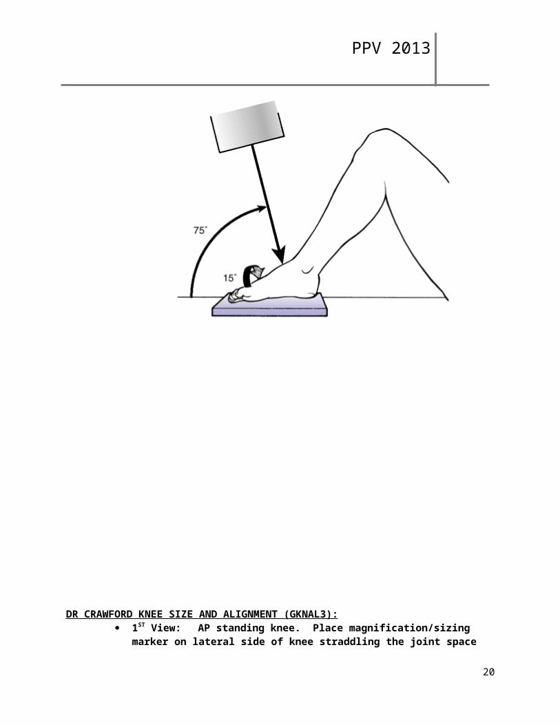
CANALE AND KELLY: Modified radiographic technique used for assessing fractures of the talar neck Technique performed with cassette placed under the foot Ankle is placed in maximal equinus facilitated by flexion of the hip and knee Foot is pronated approximately 15°, while the CR is directed cephalad at a 75° angle
from the horizontal table top View shows lateral profile of the talus without superimposed osseous structures and
the fracture and its reduction
18
PPV 2013
DR CRAWFORD KNEE SIZE AND ALIGNMENT (GKNAL3): 1ST View: AP standing knee. Place magnification/sizing marker on lateral side of
knee straddling the joint space 2nd View: Lateral single standing knee with magnification/sizing marker centered
and anterior to the joint 3rd View: hip to ankle image (scoliosis cassettes)
** Most images done at CHH**
19
PPV 2013
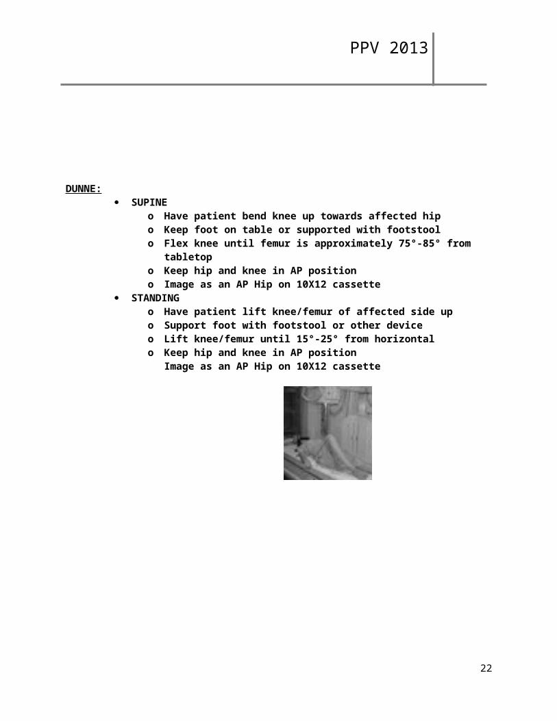
DUNNE: SUPINE
o Have patient bend knee up towards affected hipo Keep foot on table or supported with footstoolo Flex knee until femur is approximately 75°-85° from tabletopo Keep hip and knee in AP positiono Image as an AP Hip on 10X12 cassette
STANDINGo Have patient lift knee/femur of affected side upo Support foot with footstool or other deviceo Lift knee/femur until 15°-25° from horizontalo Keep hip and knee in AP position
Image as an AP Hip on 10X12 cassette
20
PPV 2013
FALSE PROFILE: 1st View: Upright pelvis 2nd View: Oblique patient 60° towards hip in question.
o Hip in question is next to upright bucky and foot is parallel with the bucky. The other foot is pointed (90°) towards tube.
o Use 14X17 cassette crosswise. o Top of film at crest.o Both hips on film. o Both femoral heads should be seen and be at least 3 finger spaces apart when
looking at it on the monitor.
21
PPV 2013
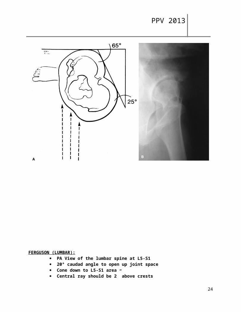
FERGUSON (LUMBAR): PA View of the lumbar spine at L5-S1 20° caudad angle to open up joint space Cone down to L5-S1 area Central ray should be 2” above crests
**If done AP - 20° cephalad angle**
22
PPV 2013
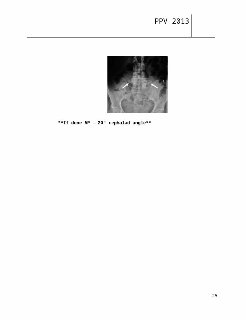
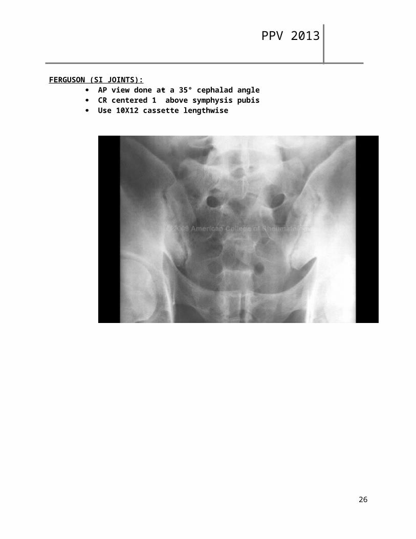
FERGUSON (SI JOINTS): AP view done at a 35° cephalad angle CR centered 1” above symphysis pubis Use 10X12 cassette lengthwise
23
PPV 2013
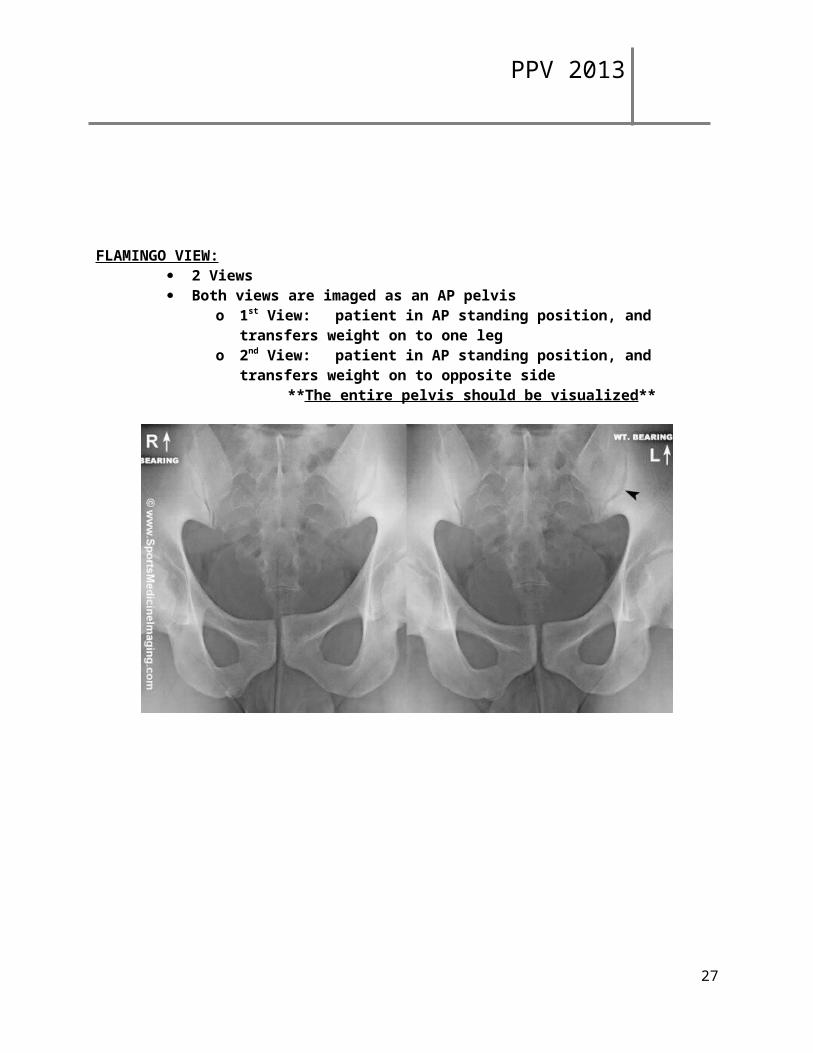
FLAMINGO VIEW: 2 Views Both views are imaged as an AP pelvis
o 1st View: patient in AP standing position, and transfers weight on to one leg
o 2nd View: patient in AP standing position, and transfers weight on to opposite side
**The entire pelvis should be visualized**
24
PPV 2013
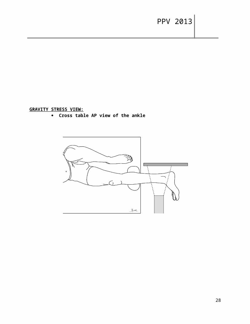
GRAVITY STRESS VIEW: Cross table AP view of the ankle
25
PPV 2013
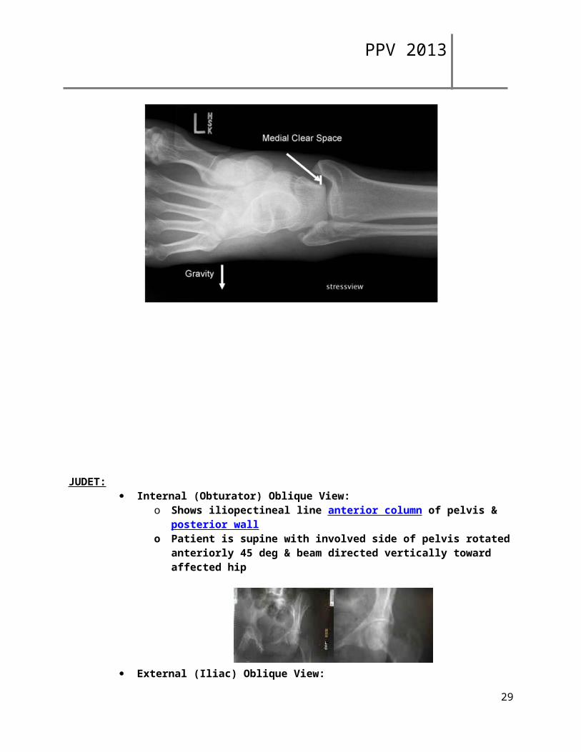
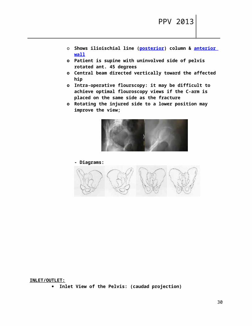
JUDET: Internal (Obturator) Oblique View:
o Shows iliopectineal line anterior column of pelvis & posterior wallo Patient is supine with involved side of pelvis rotated anteriorly 45 deg & beam
directed vertically toward affected hip
External (Iliac) Oblique View:
o Shows ilioischial line (posterior) column & anterior wallo Patient is supine with uninvolved side of pelvis rotated ant. 45 degreeso Central beam directed vertically toward the affected hipo Intra-operative flourscopy: it may be difficult to achieve optimal flouroscopy
views if the C-arm is placed on the same side as the fractureo Rotating the injured side to a lower position may improve the view;
- Diagrams:
26
PPV 2013
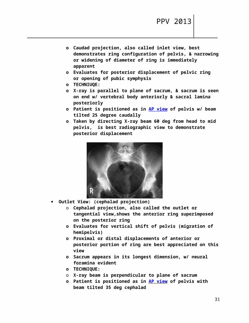
INLET/OUTLET: Inlet View of the Pelvis: (caudad projection)
o Caudad projection, also called inlet view, best demonstrates ring configuration of pelvis, & narrowing or widening of diameter of ring is immediately apparent
o Evaluates for posterior displacement of pelvic ring or opening of pubic symphysis
o TECHNIUQE:o X-ray is parallel to plane of sacrum, & sacrum is seen on end w/ vertebral body
anteriorly & sacral lamina posteriorlyo Patient is positioned as in AP view of pelvis w/ beam tilted 25 degree caudallyo Taken by directing X-ray beam 60 deg from head to mid pelvis, is best
radiographic view to demonstrate posterior displacement
Outlet View: (cephalad projection)o Cephalad projection, also called the outlet or tangential view,shows the
anterior ring superimposed on the posterior ringo Evaluates for vertical shift of pelvis (migration of hemipelvis)o Proximal or distal displacements of anterior or posterior portion of ring are
best appreciated on this viewo Sacrum appears in its longest dimension, w/ neural foramina evidento TECHNIQUE:o X-ray beam is perpendicular to plane of sacrumo Patient is positioned as in AP view of pelvis with beam tilted 35 deg cephalad
27
PPV 2013
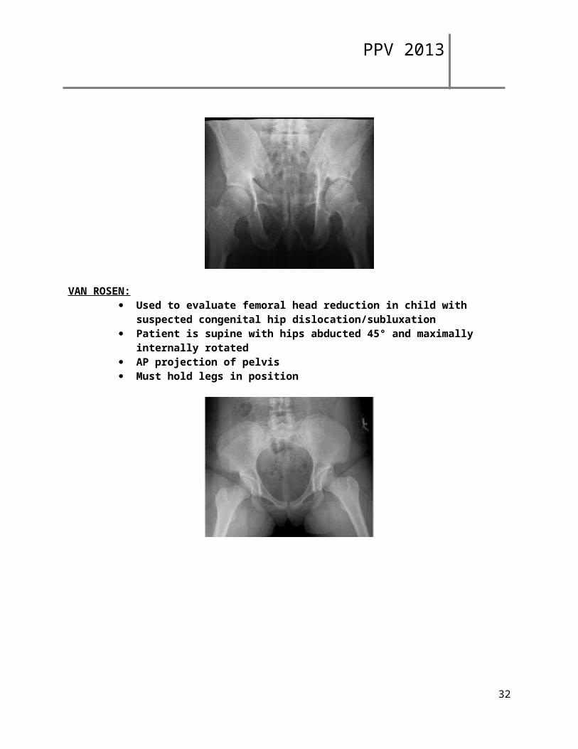
VAN ROSEN: Used to evaluate femoral head reduction in child with suspected congenital hip
dislocation/subluxation Patient is supine with hips abducted 45° and maximally internally rotated AP projection of pelvis Must hold legs in position
28
PPV 2013
Calibration Marker for hips/pelvis
Dr. Schabel and Dr. Huff both want their AP pelvis and AP hip to have a visible calibration marker on them.
For both doctors AP Standing, hip centered pelvis with calibration and AP Standing hip with calibration
Lateral for Schabel = Cross table/shoot through
Lateral for Huff = Frog leg or roll out
For the calibration marker to be accurate, it must be placed on the outside of the patient’s affected leg. Placing it in between the legs, in front of or behind the leg is inaccurate.
When placing the marker first find the greater trochanter. Place the marker ball on that spot. There is no wiggle room for the marker to be moved toward the front or back of the patient; however the marker may be moved upward toward the iliac crest or downward toward the knee as long as it is still in the same line front to back as the trochanter.
We are measuring magnification from the OID created by the patient’s rear end and soft tissue; therefore the OID from the marker ball to the bucky must be the same as the greater trochanter to the bucky.
For larger patients:
Having the patient reach the hand of the affected side down and push the marker ball into their soft tissue is one way to have it be visible on a larger patient. If that doesn’t work look for any spot that you can see a tiny bit of light behind the patient, move the ball upward or downward to that spot keeping in line front to back with the greater trochanter and have the patient push the ball inward.
Also you can off center the patient to give them a little more room on the affected side along with the above method.
If there is still no seeing the ball, then you may have to take 2 images to get the ball on 1 and a centered pelvis on the other. The patient can be off centered pretty far as long as both hip joints are still visible on the image with the marker ball. The centered image is for the radiologist to be able to accurately read the images.
29
PPV 2013
IMAGING SERVICES
LAST REVISION DATE: JUNE 2013
METASTIC BONE SURVEY
** Send to PACS in this order:
LATERAL SKULL & C-SPINE Do both on 1 - 14 x 17" cassette at upright bucky, with patient sitting.
LATERAL T-SPINE Do not collimate tight
LATERAL L-SPINE Do not collimate tight
AP UPPER RIBS & SHOULDERS Do UPPER RIBS AND SHOULDERS on a transversely positioned 14X17 cassette
AP LOWER RIBS & L-SPINE Open cone on AP L-SPINE to include LOWER RIBS
AP PELVIS
AP RIGHT & LEFT FEMUR
AP RIGHT & LEFT HUMERUS
30
PPV 2013
IMAGING SERVICES
LAST REVISION DATE: JUNE 2013
PELVIS
*Cervical collars, casts, braces, etc. shall not be removed unless specifically requested by the referring physician.
**In trauma cases, include both joints if possible; otherwise, include joint nearest to area of injury.
PELVIS (1 image) AP
INLET & OUTLET VIEWS (2 images) Inlet (use 14"x17" cassette) Outlet (use 14"x17" cassette)
HIP: NON-TRAUMA (2 images) AP Hip-Centered Pelvis Lateral Frogleg If unable to do a frogleg lateral, do a roll out lateral instead.
HIP: NON-TRAUMA FOR TOTAL HIP PROSTHESIS (2 images) *Include entire prosthesis on both views.
AP Pelvis Lateral Rollout
HIP: TRAUMA (2 images) AP Hip-Centered Pelvis Axiolateral (shoot through lateral) When there are bilateral hip fractures, do the
Clements-Nakayama modification.
JUDET VIEWS (2 images) RPO & LPO (perform on a 14"x17" and include both hip joints on each image)
31
PPV 2013
IMAGING SERVICES
LAST REVISION DATE: JUNE 2013
SKULL
*Cervical collars, casts, braces, etc. shall not be removed unless specifically requested by the referring physician.
SKULL (3 images) AP/PA Skull AP Towne Lateral
FACIAL BONES (3 images) *include mandible on all views*
PA Waters Modified Waters Lateral
MANDIBLE (5 images) PA Projection PA Axial Projection Lateral Bilateral Axiolateral Obliques
ZYGOMATIC ARCHES (4 images) PA Waters AP Modified Towne Bilateral Tangential Projections
NASAL BONES (3 images) PA Waters Bilateral Laterals
TEMPOROMANIDBULAR JOINTS (TMJs) (5 images) Bilateral Axiolateral Oblique Projections, with open (when not contraindicated) and closed
mouth AP Modified Towne
32
PPV 2013
PARANASAL SINUSES (4 images) *cone to sinuses, patient must be upright* PA Caldwell PA Waters Lateral SMV
ORBITS: TRAUMA & FOREIGN BODY (NOT PRE-MRI) (3 images) PA Waters PA Modified Waters Lateral
ORBITS: PRE-MRI (2 images) PA Waters* Lateral
*a second PA waters will only be performed if instructed to by a Radiologist
OPTIC FORAMEN (2 images) Bilateral Parietoorbital Oblique Projections (Rhese Method)
SELLA TURCICA (3 images) Lateral AP Towne PA Caldwell
MASTOIDS (5 images) Bilateral Stenvers Bilateral Laws AP Towne
33
PPV 2013
IMAGING SERVICES
LAST REVISION DATE: JUNE 2013
SPINE
CERVICAL:
*Cervical collars, casts, braces, etc. shall not be removed unless specifically requested by the referring physician.
C-SPINE; ROUTINE (3 – 4 images) AP Lateral Swimmers (Perform if unable to view C7 – T1) Odontoid
C-SPINE OBLIQUES (2 images) RAO & LAO
C-SPINE FLEXION & EXTENSION (2 images) Flexion Extension
TRAUMA C-SPINETrauma patients suspected of having severe injury to the cervical spine will receive a portable lateral view of the spine prior to the standard C-spine studies. It is of importance that the spine is cleared through C7 – T1. This may be accomplished by obtaining a lateral while the physician pulls on the patient's arms or by placing the patient in a swimmer's position (the technologist may need to over penetrate the mid section of the spine in order to visualize C7 – T1). The emergency room triage physician determines the neck trauma status prior to ordering images. Upon the completion of the lateral image, the triage physician will determine whether a consultation is necessary with the radiology staff. When it is determined that consultation is needed, the radiologist or resident will report to the emergency room for assistance and decide what further views are to be taken.
34
PPV 2013
Policy for Clearing Cervical Spine: When cervical spines need to be cleared, the AP, Lateral, and odontoid (and swimmer's view if necessary) should be shown to a radiology resident or staff. If the radiology resident or staff feels that it is safe to go ahead with flexion and extension views, this should be documented by that individual in the patient's chart.
If a cervical collar is present, it may then be removed and lateral flexion and extension views of the cervical spine are done with the patient flexing and extending unassisted.
If the C7 – T1 level is not demonstrated on the routine views, swimmer's lateral should be taken as well during the flexion and extension views.
In the uncooperative or incoherent patient who has normal AP, lateral, and odontoid views, it will be necessary for the referring attending staff or house staff to position the patient for the flexion and extension views.
Clearance under fluoroscopy is not to be done.
POST TRAUMA C-SPINE: FOR CLEARING C-SPINE (3 images) AP Cross-Table Lateral Odontoid
*perform a swimmers view if unable to see C7 – T1.
SOFT TISSUE NECK: LATERAL
o To include tip of nose through the back of the C-spine. o Patient must inhale through their nose at time of exposure.o Use soft tissue technique.o If AP is requested, elevate chin to visualize trachea.
THORACIC:
THORACIC SPINE: ROUTINE (3 images) AP Lateral Swimmers
35
PPV 2013
LUMBAR:
LUMBAR SPINE (LUMBOSACRAL): ROUTINE (3 images) AP Lateral include L5-S1 Lateral Spot only if that area is not well visualized on the Lateral or the
physician’s order requests one.
LUMBAR OBLIQUES (2 images) RAO & LAO Do RPO & LPO when necessary
LUMBAR: FERGUSON (1 image) AP
SACROILIAC JOINTS (3 images) PA RPO/LPO
SACRUM/COCCYX (3 images) AP Sacrum AP Coccyx Lateral
SCOLIOSIS (2 images) AP LATERAL
SCOLIOSIS BENDING (2 images) SUPINE AP BENDING TO THE RIGHT SUPINE AP BENDING TO THE LEFT
36
PPV 2013
IMAGING SERVICES
LAST REVISION DATE: JUNE 2013
UPPER EXTREMITY
*Cervical collars, casts, braces, etc. shall not be removed unless specifically requested by the referring physician.
**In trauma cases, include both joints if possible; otherwise, include joint nearest to area of injury.
SHOULDER: TRAUMA & NON-TRAUMA (3 images) AP Internal External/Grashey Axillary If patient is unable to do an axillary, do a Scapular Y view.
CLAVICLE (2 images) AP AP Axial
SCAPULA (2 images) AP Lateral
AC JOINTS (2 images) AP Bilateral AP Bilateral With Weights
HUMERUS (2 images) AP Lateral
ELBOW (2 images) AP Lateral
ELBOW: TRAUMA AP Lateral Radial Head (Coyle Method)
37
PPV 2013
FOREARM (2 images) AP Lateral
WRIST: TRAUMA & NON-TRAUMA (3 images) PA PA Oblique (semi-supinated) Lateral
HAND: TRAUMA & NON-TRAUMA (3 images) PA PA Oblique (semi-supinated) Lateral
HAND: ARTHRITIS Bilateral PA
FINGER: TRAUMA & NON-TRAUMA (3 images) PA Hand PA Oblique (of affected finger) Lateral (of affected finger)
THUMB: TRAUMA & NON-TRAUMA (3 images) PA Hand PA or AP Thumb Lateral Thumb
38
PPV 2013
IMAGING SERVICES
LAST REVISION DATE: JUNE 2013
SPECIAL VIEWS – UPPER
BALL IN HAND:
Supinate hands and place medial aspect of both hands together at center of IR
From this position, internally rotate hands 45° and support posterior of hands on 45°
radioloucent sponge
Extend fingers and ensure that they are relaxed, slightly separated but parallel to IR
Abduct both thumbs to avoid superimposition
39
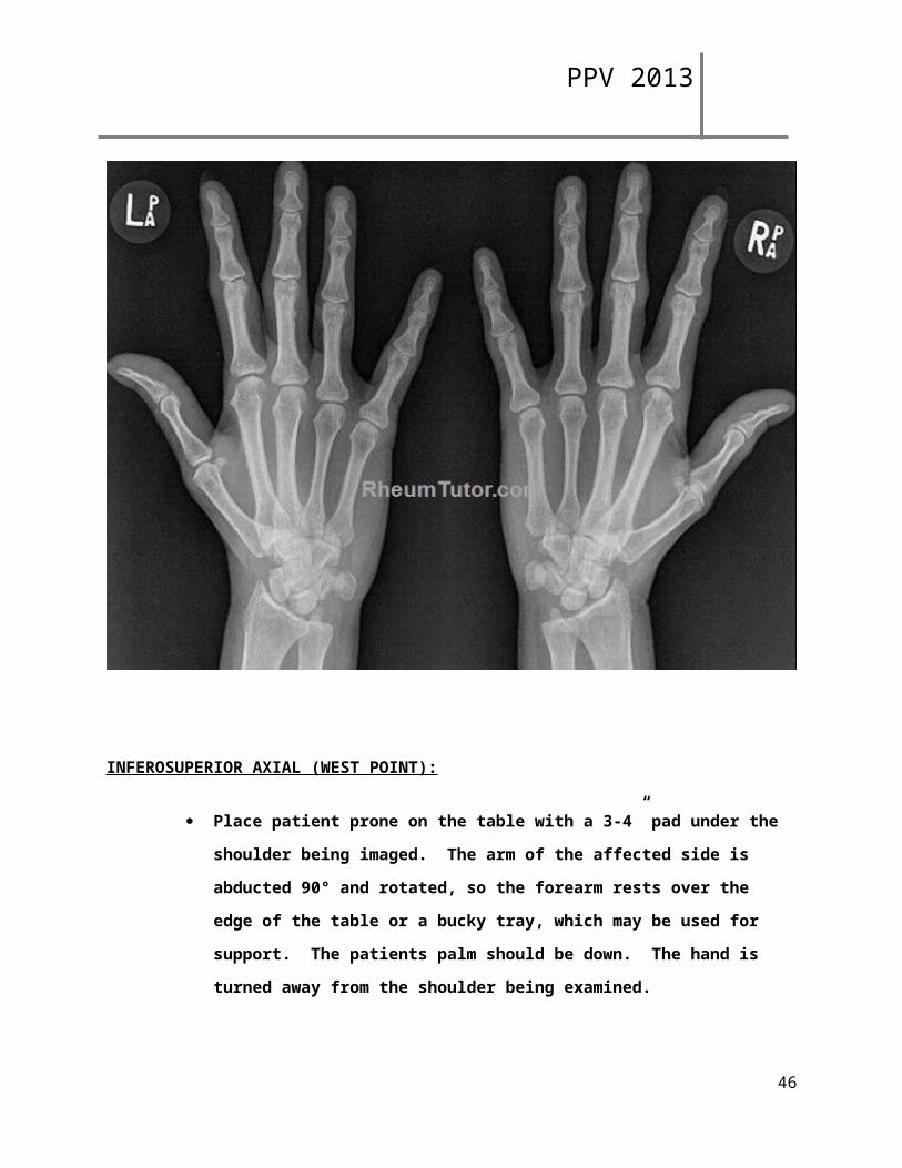
PPV 2013
INFEROSUPERIOR AXIAL (WEST POINT):
Place patient prone on the table with a 3-4” pad under the shoulder being imaged.
The arm of the affected side is abducted 90° and rotated, so the forearm rests over the
edge of the table or a bucky tray, which may be used for support. The patients palm
should be down. The hand is turned away from the shoulder being examined.
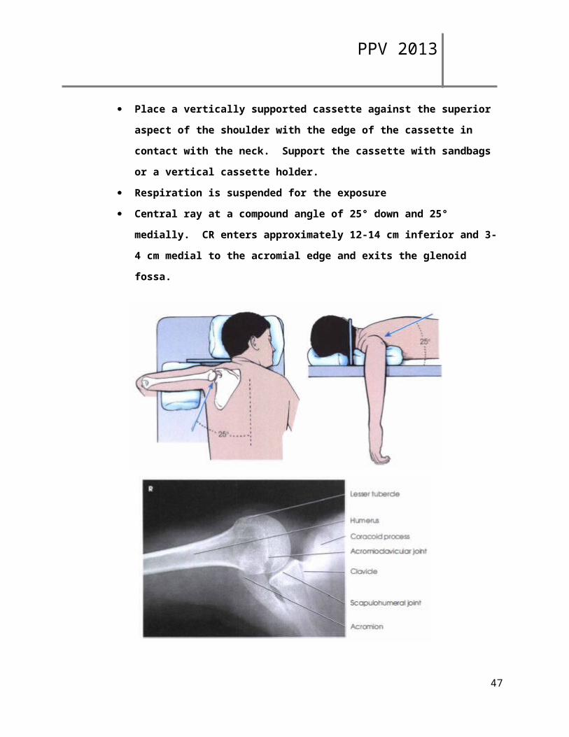
Place a vertically supported cassette against the superior aspect of the shoulder with
the edge of the cassette in contact with the neck. Support the cassette with sandbags
or a vertical cassette holder.
Respiration is suspended for the exposure
40
PPV 2013
Central ray at a compound angle of 25° down and 25° medially. CR enters
approximately 12-14 cm inferior and 3-4 cm medial to the acromial edge and exits the
glenoid fossa.
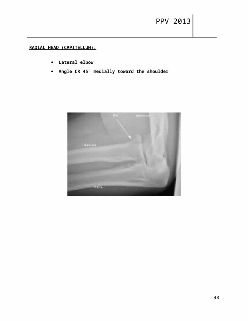
RADIAL HEAD (CAPITELLUM):
Lateral elbow
Angle CR 45° medially toward the shoulder
41
PPV 2013
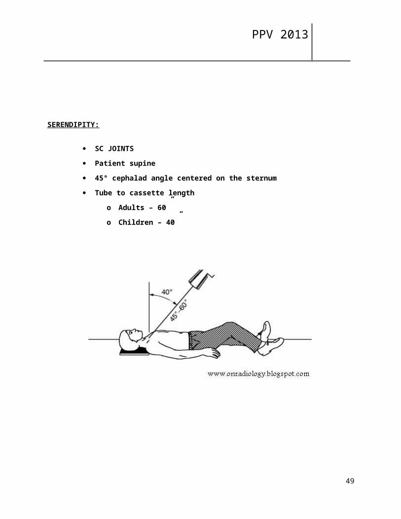
SERENDIPITY:
SC JOINTS
Patient supine
45° cephalad angle centered on the sternum
Tube to cassette length
o Adults – 60”
42
PPV 2013
o Children – 40”
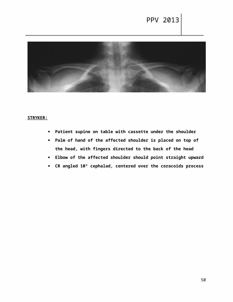
STRYKER:
Patient supine on table with cassette under the shoulder
Palm of hand of the affected shoulder is placed on top of the head, with fingers
directed to the back of the head
Elbow of the affected shoulder should point straight upward
CR angled 10° cephalad, centered over the coracoids process
43
PPV 2013
SUPRASPINATUS:
Scapular Y position
Angle CR 5-15° caudally
44
PPV 2013
SCAPULAR Y VIEW:
Accomplished by placing anterior aspect of affected shoulder against x-ray plate and rotating other shoulder out approximately 40°
45
PPV 2013
ZANCA:
Patient should be AP Angle the CR 10° cephalic
46
PPV 2013
CR directed to AC joint
47
PPV 2013
PPV OPEN/CLOSE PROCEDURE
6/2013
To Open:
Check tech area.o Assure computers are up and running ok
Ortho room (room3): **TURN THIS ROOM ON FIRST**o Assure room is clean, stocked, and ready for pt useo Turn on x-ray equipment and lights
48
PPV 2013
Genrator may take up to 45 minutes before it will shoot, be sure to turn on first!
o Check Oxygen tubing and Suction canister/tubing to assure they are clean and ready to use
RF Room 1:o Assure room is clean, stocked, and ready for pt useo Turn on x-ray equipment and over head lightso Check Oxygen tubing and Suction canister/tubing to assure they are clean and ready
to use RF Room 2:
o Assure room is clean, stocked, and ready for pt useo Turn on x-ray equipment and over head lightso Check Oxygen tubing and Suction canister/tubing to assure they are clean and ready
to use Check supplies, tape, paper, blue shorts, etc. Let Sara know if any supplies need to be ordered Linens have a barcode that is scanned, ordered, and stocked by logistics. If they are low, they will be
restocked soon. Check patient changing areas to assure they are clean
T o Close:
Check tech areao Computers are auto login
Ortho room (room 3):o Turn off x-ray equipment and lights. Do NOT shut off computers or the breakerso Assure room is clean and ready for patient use
RF Room 1:o Turn off x-ray equipment and lights. Do NOT shut off computers or the breakerso Assure room is clean and ready for patient use
RF Room 2:o Turn off x-ray equipment and lights. Do NOT shut off computers or the breakerso Assure room is clean and ready for patient use
Check supplies to see if there are any items that need to be gathered to bring over the next morning Check patient changing areas to assure they are clean and that there are no patient belongings in them
OREGON HEALTH & SCIENCE UNIVERSITY, DEPARTMENT OF RADIOLOGYRADIOGRAPHIC EXAMINATION ROUTINES
The departmental routines must be followed when a radiology consultation request is received with non-specific information as to the views to be taken. If the request cannot be verified or there is a problem concerning request vs. diagnosis, a radiologist must be consulted, and an appropriate notation shall be made in QDOC .
RADIATION PROTECTION:
49
PPV 2013
A. Meticulously collimate to exact size of cassette or anatomical part being radiographed if smaller.
B. Use gonadal shielding on all patients through age 55 unless shielding will obscure the area of interest or unless noted on the Physician’s Order to not use shielding. If there is a question as to when to shield, check with the Lead Technologist or the resident on call. If a shield is not used, the appropriate label "NGS" (no gonadal shielding) should be used. Should there be a possibility that the patient is pregnant and the fetus will be within 12 inches of the primary beam, use the pregnant patient protocol and fill out the appropriate paperwork.
QUALITY ASSURANCE:A. All radiology consultation requests are reviewed for completeness and accuracy by
quality control persons. Those persons being the Lead Technologist, modality Supervisor, radiology residents, or radiologists.
B. Finished radiographs are checked for quality, completeness, proper patient identification, lead markers, performing technologist's lead markers on image, artifacts, and proper exposure.
50