Embed Size (px)
Citation preview
PRACTICAL
Electrical and Rad APPLIEDBooks PRACTICAL
for ELECTRICITYPRACTICAL MEN
COYNEPRACTICAL APPLIED
ELECTRICITY
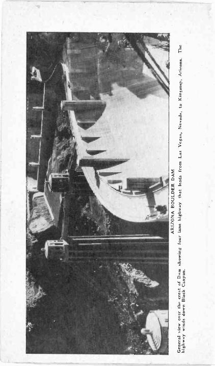
AR
IZO
NA
BO
ULD
ER
DA
MG
ener
al v
iew
ove
r th
e cr
est o
f Dam
sho
win
g fo
ur la
ne h
ighw
ay th
at le
ads
from
Las
Veg
as, N
evad
a, to
Kin
gman
, Ariz
ona.
The
high
way
win
ds d
own
Bla
ck C
anyo
n.
COYNEPRACTICAL APPLIEDELECTRICITY
A Set of Complete Practical Books
For Home Study
and
Field Reference
On
telephones, wiring, meters,
D.C. and A.C. motors, controls, and equip-ment-, household appliance repair, Rural Elec-
trification, Armature winding, Generators,Diesel Electric Plants, Automotive Electricity,
Batteries, Electrical Refrigeration and AirConditioning, Industrial Electronics, RadioElectric Welding - laws, rules, etc. - Over3,000 subjects, 5,000 Electrical facts, thou-sands of photos and diagrams.
By
THE TECHNICAL STAFF
of the
COYNE ELECTRICAL SCHOOL
Copyright 1946 byCOYNE ELECTRICAL SCHOOL
500 So. Paulina St.Chicago, Illinois
All rights reserved. This book, or any partsthereof may not be reproduced in any formwithout written permission of the Publishers.
Printed in United States of America
FOREWORD
ELECTRICITY is the greatest force known tomankind.
ELECTRICITY is leaping ahead at an unbeliev-able rate. It is moving into practically every partof the world and has become the most impoitantfactor in modern civilization. Practically everymonth the Kilowatt hour demand sets a new high-it has been doing this for the past 25 years.ELECTRICITY, even though it is one of Amer-ica's youngest industries, already employs directlyand indirectly over 3 million people.
All of our marvelous developments in Radio, Tele-vision, Electronics, Radar, etc., employ electricalpower and the principles of Electricity. It is trulyone of the world's greatest industries.
. Because of the tremendous opportunity in thefield of Electricity, there have been many bookswritten on the subject. Most treat with one specificphase of Electricity. This set of books - CoynePractical Applied Electricity (of which this volumeyou now read is an integral part)-covers the en-tire field.
This set is NEW. It includes the very latestmethods and explanations of Electrical installation,operation and maintenance.
COYNE PRACTICAL APPLIEDELECTRICITY WRITTEN BY A STAFF OF
EXPERTSMost Electrical publications are written by one
man and can therefore only cover his own specificknowledge of a subject. COYNE PRACTICALAPPLIED ELECTRICITY, however, represents
.1
FOREWORD
the combined efforts of the entire Coyne ElectricalSchool Teaching Staff and the assistance of otherauthorities on the subject. These men have a widefield and teaching experience and practical knowl-edge in electricity.and its allied branches.
HOW THIS SET WAS DEVELOPEDIn submitting any material for these books these
experts kept two things in mind - 1. MAKE ITSIMPLE ENOUGH FOR THE "BEGINNER" -2. MAKE IT COMPLETE, PRACTICAL' andVALUABLE FOR THE "OLD TIMER". Allmaterial that was submitted for these books by anyindividual was then rewritten by an editorial groupso that added explanations for the benefit of clar-ity and easier understanding could be included.
You will note that in some places in this set wehave explained and shown illustrations of the earliertypes of Electrical equipment. We had a definitepurpose in doing this, namely, that many of theearlier types of equipment are easier to understand.The basic principles of these earlier machines arethe same as the modern equipment of today. Mod-ern equipment has not materially changed in prin-ciple-it is merely refined and modernized. We havefound that it is to these early beginnings we findit advisable to turn to get a more complete under-standing of the present advanced types of electricalapparatus.
Coyne Practical Applied Electricity can pay youbig dividends every day "on the job". However, ifyou only use the set occasionally when you MUSTBE SURE before going ahead on a job-the setwill pay for itself many times over.
Coyne Practical Applied Electricity is to anelectrician what a set of complete law books is toa lawyer or a set of medical books is to a doctor.Regardless of whether a lawyer or a doctor is "juststarting out" or is an "old timer" and has beenpracticing his profession for many years he has
many occasions to refer to his reference books.Many doctors and lawyers spend thousands of dol-lars on complete sets of reference books-they findit a very wise investment.
In ELECTRICITY the need for good referencebooks is just as great. So, when you make a pur-chase of this set you are not just buying a set ofbooks-you are making an investment in your fu-ture that can pay dividends all your life.
COYNE ELECTRICAL SCHOOL
ACKNOWLEDGMENTSWe wish to acknowledge and express our appre-ciation for the assistance and co-operation givenby the following companies, in supplying data andillustrations for the preparation of this ElectricalSet.
GENERAL ELECTRIC COMPANYWESTINGHOUSE ELECTRIC & MFG. CO.ALLIS CHALM ERS MFG. CO.POWER PLANT ENGINEERING JOURNALAMERICAN BROWN BOVERI CO.CUTLER HAMMER, INC.PHILADELPHIA ELECTRIC CO.EDISON STORAGE BATTERY CO.PHILADELPHIA BATTERY CO.WALTER BATES STEEL CORP.FAIRBANKS MORSE CO.HOSKINS MFG. CO.ALLEN -BRADLEY CO.DELTA STAR MFG. CO.NATIONAL CARBON CO.CENTRAL SCIENTIFIC CO.OHIO BRASS CO.GRAYBAR ELECTRIC CO.WELSH SCIENTIFIC CO.CENTRAL SCIENTIFIC CO.
TABLE OF CONTENTS
Electricity and how it behaves - 1 - 114What Electricity will do-energy-heat-light - sound - conductors - types - in-sulators - systems - circuits - current -ammeter, Electromotive force - changes inbatteries-resistance-voltage-difference inpressure - reference points - polarity con-ductance-symbols-series and parallel con-nections-Ohms Law-N etworks-power-cells-electroplating-electrolysis.
Magnetism and Electromagnetism - 115 184Magnets-atti-action and repulsion-conse-quent poles - solenoids -circuits - windingand repair-testing-generator principles-induction coils-transformers-capacitance-di -electric constant-friction-static elec-tricity - lightning - electrostatic - rods -questions -
Electric Signal Systems - 185 - 269Systems - bells - devices - transformers-switches - wiring - troubles - burglaralarms-traps-thermal-buzzers-relays-Western Union type-Pony type-Dixietype-Clapper type-terminals-double cir-cuit-telegraph - adjustment-questions-annunciators-principles, trouble shooting-symbols-selective and return call types.
Circuits, Relays and Call Systems 271 - 321Holding relay-open circuit relays, doublerelays, 3 section alarm, combination, alarm,balancing-connections-fire alarm equip-ment-recorders-heavy duty bells, auto-matic plug-in types - vitalarm - layout -testing-trouble shooting-materials, safetyrules-estimating installation costs-ques-tions.
Telephony - 323 - 401Principles - transmitting - reproducing-parts - receivers - switches - batteries-current supply - coils - bells-polarizingmagnetos - circuits - diagrams - intercom-munication systems - central energy sys-tems-exchanges-switchboards-lamps-plugs - cables - relays - automatic tele-phones - line banks - contacts-phantomcircuits - questions.
HOW TO USETHIS SET OF BOOKS
Coyne Practical Applied Electricity will be ofuse and value to you in exact proportion to thetime and energy you spend in studying and using it.
A Reference Set of this kind is used in twodistinct ways.
FIRST, it is used by the fellow who wishes tomake Electricity his future work and uses this Ref-erence Set as a home training course.
SECOND, it is especially valuable to the manwho wishes to use it strictly as a Reference Set.This includes electricians, mechanics or anyoneworking at any trade who wishes to have a set ofbooks so that he can refer to them for informationin Electrical problems at any time.
You, of course, know into which group you falland this article will outline how to properly usethis Set to get the most value for your own per-sonal benefit.
How To Use This Set As A Home TrainingCourse In Electricity
The most important advice I can give the fellowwho wishes to study our set as a home trainingcourse in Electricity is to start from the begin-ning in Volume 1, and continue in order throughthe other 6 volumes. Don't make the mistake ofjumping from one subject to another or taking aportion of one volume and then reverting back toanother. Study the set as it has been written andyou'll get the most out of it.
Volume 1 is one of the most important of theentire Set. Every good course of training must havea good foundation. Our first volume is the founda-tion of our course and is designed to explain in
,simple language terms and expressions, laws and
How To Use This Set of Books
rules of Electricity, upon which any of the big instal-latians, maintenance and service jobs are based.So, become thoroughly familiar with the subjectscovered in the first volume and you will be able tomaster each additional subject as you proceed.
One of the improvements we made in this setwas to add "review" questions throughout thebooks. You will find these questions in most casesat the end of a chapter. They are provided so "be-ginners" or "old timers" can check their progressand knowledge of particular subjects. Our mainpurpose in including the "review" questions is toprovide the reader with a "yardstick" by which hecan check his knowledge of each subject. This fea-ture is a decided improvement in home study ma-terial.
Improved Method of Indexing
One of the features desired in any good electricalset is a good indexing system. Without it, any setdoesn't mean much because a fellow cannot findout what he wants to know without spending a lotof time. When we planned this set of books wemade sure it had the most modern system of in-dexing. Here is how these books are indexed..First,you 'will note at the front of all books that we havea TABLE OF CONTENTS. This outlines in 'ageneral way what the book covers. Then, at theback of each individual volume we have an INDEXof each specific subject covered in that volume:
In addition, we have a MASTER REFERENCEINDEX at the back of this volume. This is an in-dex that lists ALL of the specific electrical & radiosubjects in ALL of the volumes. This MASTERREFERENCE INDEX tells you the name of theelectrical subject, the volume it is to be found inand where it can be found in that volume. This...modern 3 way method of indexing gives you theopportunity to locate any subject covered in thesebooks quickly and accurately.
For the special benefit of the fellow desiring tolearn Electricity at home, we have prepared a greatnumber of diagrams and illustrations. Refer to thesepictures and diagrams in our books regularly.
How To Use This Set of Books
How To Use Coyne Practical Applied ElectricityStrictly As A Reference Set
The man who is interested in using these booksmainly for reference purposes will use it in a littledifferent way than the fellow who is trying to learnElectricity as a trade. Some of the types of fellowswho use this set strictly for reference purposes are :home owners, electricians or mechanics, garageowners, or workers, hardware store owners, farmersor anyone who has an occasional use for electricalknowledge. Those types of fellows should use thisset in the following manner.
Use The Master Index To LocateElectrical Subjects
If some particular type of electrical problem pre-sents itself, refer immediately to the Master Refer-ence Index in this volume - it will give you thesection and volume of this set in which the subjectis covered.Then, turn to that section and carefully read theinstructions outlined. Also read any other sectionsof the set mentioned in the article. As an example,in checking over some information on electric mo-tors, some reference might be made to an electricallaw of principles contained in Volume 1 of the Set.In order to thoroughly understand the procedure tofollow in working out the electrical problem, youshould refer to Volume 1 and get a better under-standing of the electrical law on principles involved.
Thousands of men use this Set in their dailyproblems, both on the job and around the homeas well. If you follow the instructions outlined youwill be able to locate any information you maywant at any time on your own electrical problems.
And here's a very important point. Althoughthis set of books starts in Volume 1 and proceedsthrough the other 6 volumes in order, it makes anideal home study course-nevertheless, any individ-ual book in the series is independent of the others and
it
can be studied separately. As an example, Volume3 covers D.C. motors and equipment. If a manwanted to get some information on D.C. machinesonly he could find it completely covered in thisvolume and it would not he essential to refer to anyother volume of the set unless he wanted someadditional information on some other electricalprinciple that would have a bearing on his problem.
This feature is especially beneficial to the "oldtimer" who plans to use the set mainly for fieldreference purposes.
We believe, however, that the entire set of 7 vol-umes should be read completely by both the "begin-ner" or the expert. In this way you get the greatestbenefit from the set. In doing so the experiencedElectrician will be able to get very valuable informa-tion on subjects that he may have thought he wasfamiliar with, but in reality he was not thoroughlyposted on a particular subject.

ELECTRICITY. AND HOW IT BEHAVES
Among all the ideas about what electricity is andhow it acts there is one theory that will help us agreat deal in understanding all electrical devices,even those of radio and electrochemistry. To ex-plain this theory we may start by considering amolecule. A molecule is the smallest particle of anygiven substance. For example, a molecule of saltis the smalest particle of salt which may exist andstill remain salt. If we further divide a molecule ofsalt we no longer have salt, but have one atom ofthe element sodium and one atom of the elementchlorine.
.Of the elements there are ninety-two in all,among them being sodium and chlorine along withsuch familiar things as iron and such unfamiliarones as protoactinium. These elements combine invarious ways to make up all known substances.Water, as you probably know, consists of two atomsof the element hydrogen and one atom of the ele-ment oxygen.
Every atom is believed to include in its makeupa central part, often called the proton, and aroundthis central part one or more electrons. The centralpart of the atom remains fixed in its position, butunder certain conditions some electrons may be-come separated from the atoms and wander looseor become associated with other atoms.
The electrons are considered to be particles ofelectricity itself. When electrons move through thebody of a substance, as through a copper wire, wehave moving electricity or the electric current.Application of sufficient electrical force will causeelectrons to leave the substance and travel throughthe surrounding space. This is what happens inradio tubes, in television tubes, in X-ray tubes, andin fluorescent lamps.
No one has yet seen an electron. It has beensaid that an electron in an atom would be comparable in size to a fly in a cathedral. The atom, in
Electricity, and How It Behaves
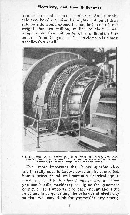
turn, is far smaller than a molecule. And a mole-cule may be of such size that eighty million of themside by side would extend. for one inch, and of suchweight that ten million, million of them wouldweigh about five millionths- of a millionth of anounce. From this you see that an electron is almostunbelievably small.
Fig. 5. Large D. C. generator. It is rated as follows. 2000 Kw..250 V., 8000 1. After carefully reading the pages on- units and
symbols, you should easily understand this rating.
Even more important than knowing what elec-tricity really is, is to know how it can be controlled,how to select, install and maintain electrical equip-ment, and what to do when things go wrong. Thenyou can handle machinery as big as the generatorof Fig. 5. It is important to learn enough about therules and taws governing the behavior of electricityso that you may think for yourself in any emerg-
2
Electricity, and How It Behaves
ency. This does not mean that you need studyelectrical engineering, for that involves highermathematics and other sciences, but it does meanthat you should be thoroughly conversant with prac-tical electricity or applied electricity.WHAT ELECTRICITY WILL DO
Before getting on with our classification of elec-trical apparatus and devices there are two factsabout electricity that shOuld be understood.
To begin with, energy may exist in many differ-ent forms such as mechanical energy, chemicalenergy, electrical energy, heat energy, light energy,physical energy, etc. According to a basic law,these different types of energy cannot be created,nor can they be destroyed; however, they may bereadily converted from one form to another.
First: at least ninety-nine per cent of all usefulapplications of electricity require that the electricitybe in motion. Electricity standing still is no moreuseful, so far as doing work is concerned, than is astationary belt between a steam engine and a ma-chine which is to be driven. Electricity in motionis called the electric current. If you knew all thereis to know about the behavior of moving electricityyou could stop right here and get a job at fifty or ahundred or more thousands of dollars a year-foryou would know more than anyone else who everhas lived.
Second : electricity in motion, or the electric cur-rent, provides the most effective means ever dis-covered for carrying energy from one place to an-other, and of changing one form of energy to an-other form of energy. To make this statementclearer we should know the meaning of energy.
Energy enables you to shovel coal. Energy is theability to do work. The physical energy you putto use when shoveling coal is converted to energyof motion. The whirling fly -wheel of a steam engineor a, gasoline engine contains energy of motion,which we may call mechanical energy. Any andevery moving object contains this kind of energy.
3
Electricity, and How It Behaves
The stone thrown by a small boy contains energyof motion, which will do the work of breakinga window.
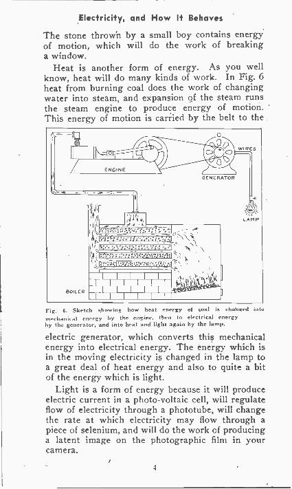
Heat is another form of energy. As you wellknow, heat will do many kinds of work. In Fig. 6heat from burning coal does the work of changingwater into steam, and expansion of the steam runsthe steam engine to produce energy of motion.This energy of motion is carried by the belt to the
ENGINE
BOILER
;44 4kiA
0
GENERATOR
f..°,7,,
S'it
\, ye , e
11111==11111
WIRES
LAMP
Fig. 6. Sketch showing how heat energy of coal is changed intomechanical energy by the engine, then to electrical energyby the generator, and into heat and light again by the lamp.
electric generator, which converts this mechanicalenergy into electrical energy. The energy which isin the moving electricity is changed in the lamp toa great deal of heat energy and also to quite a bitof the energy which is light.
Light is a form of energy because it will produceelectric current in a photo -voltaic cell, will regulateflow of electricity through a phototube, will changethe rate at which electricity may flow through apiece of selenium, and will do the work of producinga latent image on the photographic film in yourcamera.
4
Electricity, and How It Behaves
The dry cell in your flash lamp and the storagebattery in your automobile contain chemical energy.When chemical changes take place in the flash lampcell or the automobile battery these changes pro-duce the energy which is electric current. Thismoving electricity will produce heat and light in theflash lamp or in an automobile headlamp, will pro-duce motion in an automobile starting motor, willproduce 'spark, at the spark plug-, in the automobileengine, and \\ ill produce sound from the auto horn.
Sound is a form of energy, because sound wavesreally are vibratory movements of air or other sub-stances through which sound travels. Any motionrequires energy.
One of the most important and interesting kindsof energy is radiant energy which travels througha complete vacuum even better than through air,and which will travel through other gases, liquids,and even through solids. It is radiant energy, orradiation, which is responsible for the transmissionof radio signals, for X-rays, for the radiant heat thatcomes to the earth from the sun through 93 millionmiles of empty space.
By the use of suitable apparatus any form of en-ergy may be converted to electrical energy. Me-chanical motion, heat, light, chemical energy, sound,and radiation-all are capable of producing anelectric current.
The energy of the electric current, or of electricityin motion, may be converted to any other formof energy-mechanical motion, heat, light, chemicalenergy, sound, or radiation. It is just a matter ofusing appropriate apparatus.
Now we are commencing to get at the reasonswhy electricity in motion is the greatest and mostimportant force in the world. It is the universalmeans for changing one kind of energy into otherkinds. It is the only means by which we may trans-
Electricity, and How It Behaves
mit power in large quantities from where it ischeaply or conveniently produced to somewhereelse, hundreds of miles away, where the power maybe used to advantage.
ELECTRICAL CONDUCTORSMany of the electrons in a piece of copper are
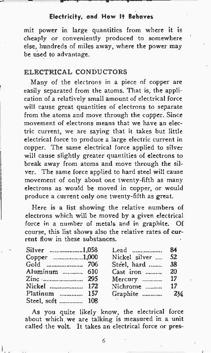
easily separated from the atoms. That is, the appli-cation of a relatively small amount of electrical forcewill cause great quantities of electrons to separatefrom the atoms and move through the copper. Sincemovement of electrons means that we have an elec-tric current, we are saying that it takes but littleelectrical force to produce a large electric current incopper. The same electrical force applied to silverwill cause slightly greater quantities of electrons tobreak away from atoms and move through the sil-ver. The same force applied to hard steel will causemovement of only about one twenty-fifth as manyelectrons as would be moved in copper, or wouldproduce a current only one twenty-fifth as great.
Here is a list showing the relative numbers ofelectrons which will be moved by a given electricalforce in a number of metals and in graphite. Ofcourse, this list shows also the relative rates of cur-rent flow in these substances.
Silver 1,058 Lead 84Copper 1,000 Nickel silver .... 52Gold 706 Steel, hard 38Aluminum 610 Cast iron 20Zinc 295 Mercury 17Nickel 172 Nichrome 17Platinum 157 GraphiteSteel, soft 108
As you quite likely know, the electrical forceabout which we are talking is measured in a unitcalled the volt. It takes an electrical force or pres-
6
Electricity, and How It Behaves
sure of 100 to 120 volts to drive electricity throughan ordinary household incandescent lamp at a ratewhich causes the lamp to light with normal brilli-ancy. Each small dry cell in an electric flash lampis capable of delivering a force or difference in pres-sure of 1%2 volts. Each cell of an automobile storagebattery is capable of delivering a force of 2 volts,and in the usual three -cell battery there is availablea total force of 6 volts.
Anv substance in which an electrical force orelectrical difference in pressure will separate rela-tively large quantities of electrons from the atoms,and cause the electrons to move in a steady flowthrough the substances, is called an electrical con-ductor. Not only all the metals in our list, but allother metals are conductors. Some, like copper andaluminum, are good conductors meaning that theypermit flow of many electrons or of a large currentwith relatively little force. Others, like soft steel,are fair conductors. Still others, like Nichrome, arevery poor conductors and are used where we wishdeliberately to hinder or resist the flow of electriccurrent.
Copper is by far the most important electricalconductor, both because of the ease with which itpermits flow of current and because of its abundanceand low cost. Next in industrial importance comesaluminum, and third is steel. Steel frequently isused not only in electric wires, but also where it
' already forms part of a structure or framework inwhich it is desired to carry the electric current.Some liquids are excellent conductors, notablywater in which has been mixed any kind of salt orany acid.INSULATORS
If two copper wires or other conductors shouldtouch each other while carrying electric currents,electricity from one conductor would pass into theother and thus would escape from the path whichwe desire to have it follow through the first con-ductor.
Electricity, and How It Behaves
To prevent the escape of electric current fromconductors into other conductors or into human .bodies, all current -carrying conductors should besurrounded and isolated or supported by materialswhich are not conductors. Any material which isnot a conductor is called a non-conductor or aninsulator.
Insulators or insulating materials include all sub-stances in which it is very difficult to cause a flowof current with any electrical force which may beapplied. Among the insulators which are most use-ful in electrical work are the following :
Porcelain PaperGlass CottonMica LinenBakelite and similar Silk
compounds Various oilsHard rubber Various waxesSoft rubber' Air
In an insulating material it is possible for an elec-trical force to drive many of the electrons a littleway out of their normal positions in the atoms, butnearly all the electrons still remain bound to theiratoms and will return to their normal positions theinstant the electrical force is removed. In an in-sulator it is impossible to free more than a veryfew electrons from the atoms, or to produce morethan the most minute trace of electric current.
Supposing the insulating material were a sheetof glass about inch thick. Depending on thekind or grade of glass, no appreciable current would
Electrical Circuits
flow through it until you had raised the pressure tosomewhere between 300,000 and 1,500,000 volts, or tobetween three thousand and fifteen thousand timesthe pressure needed in an incandescent lamp. At thatterrific pressure the glass would puncture, the elec-tric pressure would force a hole right through theglass. Then current would flow through the airin the hole, because it takes a force of only about10,000 volts to force electricity through inch ofair.
Instead of the sheet of glass supposing you wereto use a small cube of glass measuring y, inch onone side. The opposition of that piece of glass toflow of current through it would be a thousandmillion, million, million times as great as the oppo-sition of a piece of copper of the same size. Therate of current flow through the glass would becorrespondingly smaller than through the copper,and, as you will agree, could be called infinitesimal.
Every insulating material mentioned in the pre-ceding list has millions and millions of times theopposition or resistance to flow of current that isoffered by any of the metals, by graphite, or byconductive liquids. Were it not for this fortunatefact we would have no more success in keepingelectricity within the paths which we wish it tofollow than would a plumber with water if hehad no pipes or other devices to confine the water.
AN ELECTRICAL SYSTEMWe started out to talk about a classification into
which might be fitted the parts of any electrical in-stallation, but had to wander rather far afield ingetting ready to understand our classification. How-ever, we finally are ready to go ahead.
To begin with we must have available some formof energy. In the case of the dry cell or some othertype of "primary" cell or battery, the originalenergy comes from nothing electrical. Even withthe cells and batteries the original energy is notelectrical but is chemical. The source of energy
9
Electrical Circuits
may be mechanical motion, heat, light, sound, orradiation. Having the original source of energy wemay proceed to the electrical groups, which areas follows:
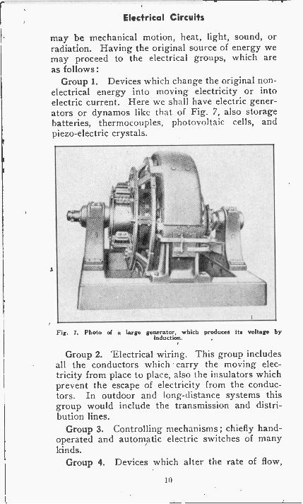
Group 1. Devices which change the original non-electrical energy into moving electricity or intoelectric current. Here we shall have electric gener-ators or dynamos like that of Fig. 7, also storagebatteries, thermocouples, photovoltaic cells, andpiezo-electric crystals.
Fig. 7. Photo of a large generator, which produces its voltage byinduction.
Group 2. Electrical wiring. This group includesall the conductors which carry the moving elec-tricity from place to place, also the insulators whichprevent the escape of electricity from the conduc-tors. In outdoor and long-distance systems thisgroup would include the transmission and distri-bution lines.
Group 3. Controlling mechanisms ; chiefly hand -operated and automatic electric switches of manykinds.
Group 4. Devices which alter the rate of flow,
10
Electrical Circuits
the difference of pressure, or some other character-istic of the moving electricity. This group includestransformers, converters, inverters, motor -genera-tors and other apparatus with which we shall be-come well acquainted.
Group 5. Meters or measuring instruments forindicating, and sometimes for making records of,the conditions existing in all parts of the electricalsystem.
Group 6. Apparatus for changing the energy of themoving electricity into some other form of energywhich we wish to use. This is a big group. In itwe shall find motors, like that of Fig. 8, electro-magnets, storage batteries, electrochemical vats,electric arcs, electric furnaces, various inductors orcoils, electrical resistors, many varieties of lamps,radiating systems for radio transmitters, electricaldischarge devices, and many other parts which areof importance in certain lines of work. All thesedevices use the electric current to produce mechan-ical motion, heat, light, sound, chemical changes,or radiation.A TYPICAL SYSTEM
To learn how our classification will work outwhen applied to an actual electrical system let'sexamine the electrical parts used on an automobile.We select the auto -electric system because youprobably are more familiar with the starter, lamps,horn and ignition for an automobile.
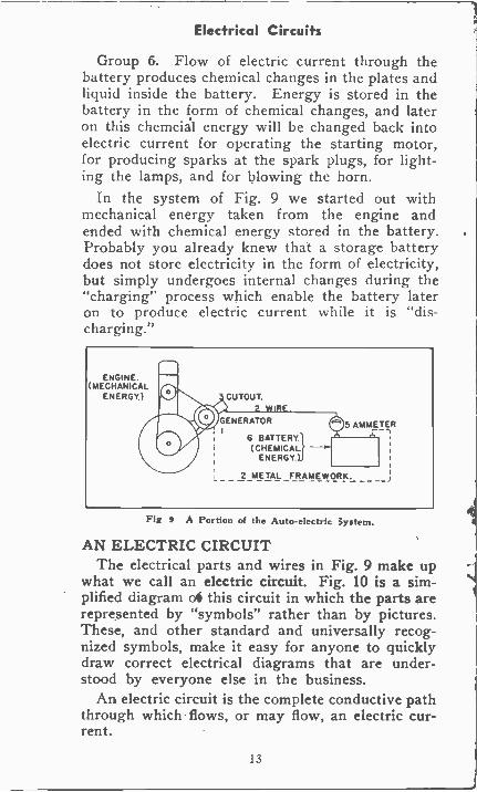
Fig. 9 shows the auto -electrical parts which weshall consider first. The initial source of energyis the automobile engine which produces mechanicalmotion. From here we may go on with our classi-fication according to the numbered groups as pre-viously listed. Corresponding numbers are on Fig. 9.
Group 1. The generator receives mechanicalenergy of motion from the engine through a belt,and changes this mechanical energy into electricalenergy. Compare this with our original definitionof group 1.
Group 2. Electric current flows to the battery
11
Electrical Circuits
through a copper wire covered with insulation, andfrom the battery flows through the steel of the auto-mobile chassis back to the generator.
Group 3. The cutout is an automatic electricalswitch which, when the generator has attainedspeed sufficient to force electricity through the bat-tery, connects the internal parts of the generatorto the wire going to the battery. The cutout is ourcontrolling mechanism.
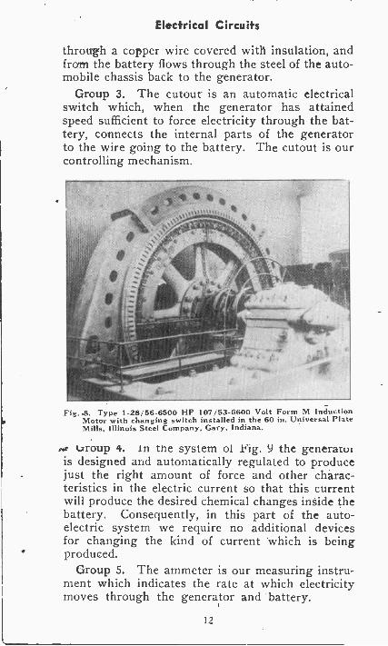
Fig..8. Type 1-28,56-6500 HP 107/53-6600 Volt Form M InductionMotor with changing switch installed in the 60 in. Universal PlateMills, Illinois Steel Company, Gary, Indiana.
urroup 4. In the system of 9 the generatoiis designed and automatically regulated to producejust the right amount of force and other charac-teristics in the electric current so that this currentwill produce the desired chemical changes inside thebattery. Consequently, in this part of the auto -electric system we require no additional devicesfor changing the kind of current 'which is beingproduced.
Group 5. The ammeter is our measuring instru-ment which indicates the rate at which electricitymoves through the generator and battery.
12
Electrical Circuits
Group 6. Flow of electric current through thebattery produces chemical changes in the plates andliquid inside the battery. Energy is stored in thebattery in the form of chemical changes, and lateron this chemcial energy will be changed back intoelectric current for operating the starting motor,for producing sparks at the spark plugs, for light-ing the lamps, and for blowing the horn.
In the system of Fig. 9 we started out withmechanical energy taken from the engine andended with chemical energy stored in the battery.Probably you already knew that a storage batterydoes not store electricity in the form of electricity,but simply undergoes internal changes during the"charging" process which enable the battery lateron to produce electric current while it is "dis-charging."
ENGINE.(MECHANICAL
ENERGY.) CUTOUT.
GENERATOR
6 BATTERY.
ENERGY.)
5 AMMETER
2 METAL FRAMEWORK. -J
Fig 9 A Portion of the Auto -electric system.
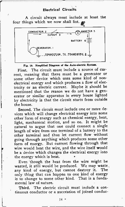
AN ELECTRIC CIRCUITThe electrical parts and wires in Fig. 9 make up
what we call an electric circuit. Fig. 10 is a sim-plified diagram o4 this circuit in which the parts arerepresented by "symbols" rather than by pictures.These, and other standard and universally recog-nized symbols, make it easy for anyone to quicklydraw correct electrical diagrams that are under-stood by everyone else in the business.
An electric circuit is the complete conductive paththrough which flows, or may flow, an electric cur-rent.
13
Electrical Circuits
A circuit always must include at least thefour things which we now shall list.
CONDUCTOR. 2CUTOUT 3
AMMETER 5
BATTERY 6
GENERATOR. I
CVINEG_TION TO FRAMEWORK.1
Fig. is. Simplified Diagram of the Auto -electric System.
First. The circuit must include a source of cur-rent, meaning that there must be a generator orsome other device which uses some kind of non-electrical energy and which produces a flow of elec-tricity or an electric current. Maybe it should bementioned that the reason we do not have a gen-erator or similar apparatus in every house lightedby electricity is that the circuit starts from outsidethe house.
Second. The circuit must include one or more de-vices which will change electrical energy into someother form of energy such as chemical energy, heat,light, mechanical motion, and so on. It might benatural to argue that one could connect a singlelength of wire from one terminal of a battery to theother terminal and thus let current flow withoutgoing through anything which produces some otherform of energy. But current flowing through thatwire would heat the wire, and the wire itself wouldbe a device which changes the electrical energy intothe energy which is heat.
Even though the heat from the wire might bewasted, it still would be produced. We may wasteany kind of energy, but cannot destroy it. Theonly thing that can happen to one kind of energyis to change to some other kind. That is a funda-mental law of nature.
Third. The electric circuit must include a con-tinuous conductor or a succession of joined conduc-
14
Electrical Circuits
tors through which electricity may flow from thesource of prent to the devices which use the cur-rent to produce some other form of energy.
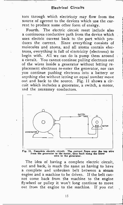
Fourth. The electric circuit must include alsoa continuous conductive path from the device whichuses electric current back to the part which pro-duces the current. Since everything consists ofmolecules and atoms, and all atoms contain elec-trons, everything is full of electricity (electrons) tobegin with. All we can do is pump them arounda circuit. You cannot continue pulling electrons outof the wires inside a generator without letting re-placement electrons re-enter the generator, nor canyou continue pushing electrons into a battery oranything else without letting an equal number moveout and back to the source. Fig. 11 shows a cir-cuit which includes a generator, a switch, a motor,and the necessary conductors.
Fig. 11. Complete electric circuit. The current flows over the top wirefrom the generator to the motor, then hack along the lower
wire to the generator.
The idea of having a complete electric circuit,out and back, is much the same as having to havea complete and unbroken belt between a steamengine and a machine to be driven. If the belt can-not come back from the machine to the engineflywheel or pulley it won't long continue to moveout from the engine to the machine. If you cut
15
Electrical Current
either side of the belt you will prevent transferof energy from the engine to the machine. It makesno difference which side of the belt you cut. Justas truly you will prevent transfer of electricalenergy from a source of current to a consumingdevice if you open either side of the circuit. Itmakes no difference which side. Many hopeful"electricians" have tried to beat this rule, but nonehave succeeded.
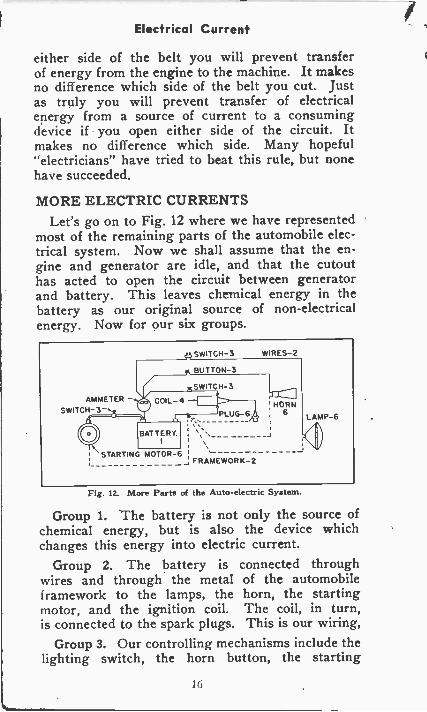
MORE ELECTRIC CURRENTSLet's go on to Fig. 12 where we have represented
most of the remaining parts of the automobile elec-trical system. Now we shall assume that the en-gine and generator are idle, and that the cutouthas acted to open the circuit between generatorand battery. This leaves chemical energy in thebattery as our original source of non -electricalenergy. Now for our six groups.
AMMETERSWITCH- 3
BATTERY.
SWITCH -3 WIRES -2
BUTTON -3
SWITCH -3
PLUG -6.
STARTING MOTOR -6 :
FRAMEWORK -2
HORN6 LAMP -6
Fig. 12. More Parts of the Auto -electric System.
Group 1. The battery is not only the source ofchemical energy, but is also the device whichchanges this energy into electric current.
Group 2. The battery is connected throughwires and through the metal of the automobileframework to the lamps, the horn, the startingmotor, and the ignition coil. The coil, in turn,is connected to the spark plugs. This is our wiring,
Group 3. Our controlling mechanisms include thelighting switch, the horn button, the starting
16
Electrical Current
switch, and the ignition switch.Group 4. The maximum difference in pressure (in
volts) which the battery can develop is not enoughto force electricity across the air gaps in the sparkplugs and produce the intensely hot arc that ignitesthe mixture of gasoline and air in the cylinders.Consequently, we must employ the ignition coil, adevice which uses current at the electrical pressuresupplied by the battery and furnishes a pressuresufficient to force electricity across the spark pluggaps. The ignition coil is a kind of electrical trans-former which converts the 6 volt pressure we haveavailable into a pressure of 10,000 volts or more,suitable for the job to be done.
Group 5. The ammeter which previously wehave used to indicate the rate at which electricityflows through the generator -battery circuit is nowused to indicate the rate at which electricity flowsthrough the battery and the lamps, the horn, andthe ignition coil. In actual practice we probablywould not carry horn current through the ammeter.The rate of current flow through the starting motoris so great that it .would ruin this small ammeter,so the starting current is not carried through themeter.
Group 6. The apparatus which changes energyof the moving electricity into other forms of energyincludes (1) the lamps which produce the energywhich is light, (2) the horn which produces theenergy which is sound, (3) the spark plugs whichproduce the energy of heat. and (4) the startingmotor which produces the energy of mechanicalmotion.
In the whole automobile electrical system (Figs.9 and 12) we commenced with mechanical energyof motion from the engine, changed it to electricalenergy in the generator, then to chemical energy inthe battery, then changed this chemical energy intolight, sound, heat, and more mechanical energy ormotion. All electrical systems are like that, just
17
Electrical Current
changing one kind of energy into other kinds whichsuit our needs.QUANTITIES OF ELECTRICITY
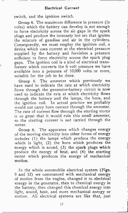
Quantities of potatoes are measured by the bushel,quantities of water may be measured by the gallonor by the cubic foot, and for everything else thereare various units in which their quantities may bemeasured. Quantities of electricity are measured bythe coulomb. A coulomb is just as definite a quan-tity of electricity as is a cubic foot a quantity ofwater.
Fig is. A "Voltammeter^ Which Measures Quantities at Electeisity.
We might define the coulomb by stating the num-ber of electrons in a coulomb, but rather than getinto figures running into uncountable billions ofelectrons we define a coulomb by stating what itwill do. In Fig. 13 the jar at the left contains twocopper plates immersed in a solution of silvernitrate, with the plates connected to a batterywhich will cause a flow of electricity. When onecoulomb of electricity flows through the solutionfrom one plate to the other this much electricitywill take out of the solution and deposit on oneof the plates about 1/25000 ounce of silver. Whetherthis quantity of electricity passed in a second, anhour or a month, it still would take with it anddeposit the same amount of silver.
Except in the eletroplating of metals and similarjobs we seldom need talk about quantities of elec-tricity such as might be measured in coulombs,
18
Electrical Current
but an understanding of the coulomb as a unit ofquantity makes it easier to understand the realmeaning of electric current and how current ismeasured.
ELECTRIC CURRENTIn order to turn a water wheel so that it will fur-
nish a desired amount of driving power it is neces-sary that water flow over or through the wheel ata rate of some certain number of cubic feet (orgallons) per second. We may define the rate ofwater flow as so many cubic feet per second. Justas the rate of flow of water is measured in somany cubic feet per second, so is the electric cur-rent measured in so many coulombs per second.
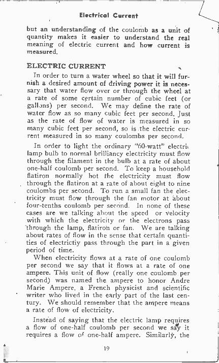
In order to light the ordinary "60 -watt" electriclamp bulb to normal brilliancy electricity must flowthrough the filament in the bulb at a rate of aboutone-half coulomb per second. To keep a householdflatiron normally hot the electricity must flowthrough the flatiron at a rate of about eight to ninecoulombs per second. To run a small fan the elec-tricity must flow through the fan motor at aboutfour -tenths coulomb per second. In none of thesecases are we talking about the speed or velocitywith which the electricity or the electrons pass'through the lamp, flatiron or fan. We are talkingabout rates of flow in the sense that certain quanti-ties of electrictiy pass through the part in a givenperiod of time.
When electricity flows at a rate of one coulombper second we say that it flows at a rate of oneampere. This unit of flow (really one coulomb persecond) was named the ampere to honor AndreMarie Ampere, a French physicist and scientificwriter who lived in the early part of the last cen-tury. We should remember that the ampere meansa rate of flow of electricity.
Instead of saying that the electric lamp requiresa flow of one-half coulomb per second we say itrequires a flow of one-half ampere. Similarly, the
19
Electrical Current
flatiron takes a flow of eight to nine amperes, andthe fan motor takes about four -tenths ampere.
o.c.AMMETER4. 5 6
oti o
WELCH
h
11111111111111111,111111nualiliillillninviiiiiill!
Fig. 14. An Ammeter for Measuring Electric Current Flow.
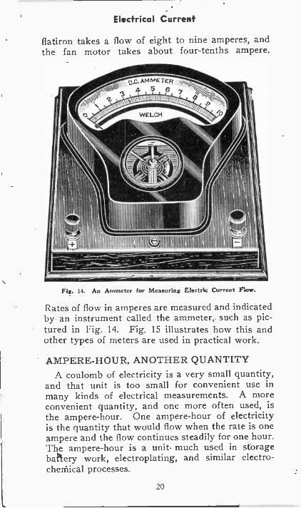
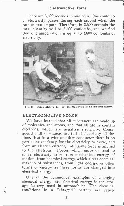
Rates of flow in amperes are measured and indicatedby an instrument called the ammeter, such as pic-tured in Fig. 14. Fig. 15 illustrates how this andother types of meters are used in practical work.
AMPERE -HOUR, ANOTHER QUANTITYA coulomb of electricity is a very small quantity,
and that unit is too small for convenient use inmany kinds of electrical measurements. A moreconvenient quantity, and one more often used, isthe ampere -hour. One ampere -hour of electricityis the quantity that would flow when the rate is oneampere and the flow continues steadily for one hour.The ampere -hour is a unit much used in storagebattery work, electroplating, and similar electro-chemical processes.
20
Electromotive Force
There are 3,600 seconds in one hour. One coulomb3f electricity passes during each second when therate is one ampere. Therefore, in 3,600 seconds thetotal quantity will be 3,600 coulombs, and we findthat one ampere -hour is equal to 3,600 coulombs ofelectricity.
Fig. 15. Using Meters To Test the Operation of an Electric Motor.
ELECTROMOTIVE FORCEWe have learned that all substances are made up
of molecules and atoms, and that all atoms containelectrons, which are negative electricity. Conse-quently, all substances are full of electricity all thetime. But in a wire or other conductor there is noparticular tendency for the electricity to move, andform an electric current, until some force is appliedto the electrons. Forces which move or tend tomove electricity arise from mechanical energy ofmotion, from chemical energy which alters chemicalmakeup of substances, from light energy, or otherforms of energy as these forms are changed intoelectrical energy.
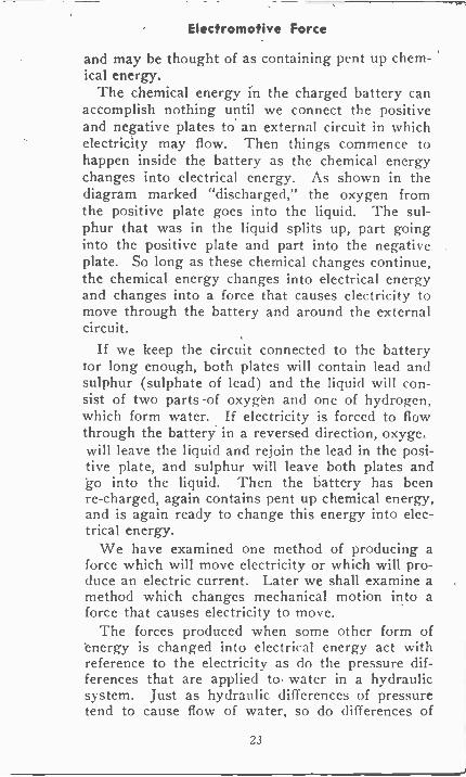
One of the commonest examples of changingchemical energy into electrical energy is the stor-age battery used in automobiles. The chemicalconditions in a "charged" battery are repre-
21
Electromotive Force
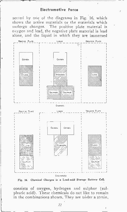
sented by one of the diagrams in Fig. 16, whichshows the active materials or the materials whichundergo changes. The positive plate material isoxygen and lead, the negative plate material is leadalone, and the liquid in which they are immersed
POSITIVE PLATE. Liam NEGATIVE PLATE.
I OXYGEN
L L
POSITIVE PLATE
OXYGEN
HYDROGEN .,
SULPHUR. SULPHUR. \&\CHARGED.
LIQUID
OXYGEN. OXYGEN
HY OROGEN//
L
NEGATIVE PLATE
_
DISCHARGED
Fig. 16. Chemical Changes in a Lead -acid Storage Battery Cell.
consists of oxygen, hydrogen and sulphur (sul-phuric acid). These chemicals do not like to remainin the combinations shown. They are under a strain,
22
Electromotive Force
and may be thought of as containing pent up chem-ical energy.
The chemical energy in the charged battery canaccomplish nothing until we connect the positiveand negative plates to an external circuit in whichelectricity may flow. Then things commence tohappen inside the battery as the chemical energychanges into electrical energy. As shown in thediagram marked "discharged," the oxygen fromthe positive plate goes into the liquid. The sul-phur that was in the liquid splits up, part goinginto the positive plate and part into the negativeplate. So long as these chemical changes continue,the chemical energy changes into electrical energyand changes into a force that causes electricity tomove through the battery and around the externalcircuit.
If we keep the circuit connected to the batteryfor long enough, both plates will contain lead and
lead) and the liquid will con-sist of two parts of oxygen and one of hydrogen,which form water. If electricity is forced to flowthrough the battery in a reversed direction, oxyge.will leave the liquid and rejoin the lead in the posi-tive plate, and sulphur will leave both plates andgo into the liquid. Then the battery has beenre -charged, again contains pent up chemical energy,and is again ready to change this energy into elec-trical energy.
We have examined one method of producing aforce which will move electricity or which will pro-duce an electric current. Later we shall examine amethod which changes mechanical motion into aforce that causes electricity to move.
The forces produced when some other form ofenergy is changed into electrical energy act withreference to the electricity as do the pressure dif-ferences that are applied to water in a hydraulicsystem. Just as hydraulic differences of pressuretend to cause flow of water, so do differences of
23
Electromotive Force
electrical pressure tend to cause flow of electricity.An electrical pressure diff6rence or force that movesor tends to move electricity, and form a current,is called an electromotive force. The abbreviationfor electromotive force is emf. We generally speakof such a force as an "ee-em-eff", pronouncing theletters of the abbreviation rather than using the fullname.
Devices such as batteries and generators in whichsome other form of energy changes to electromotiveforce are called energy sources, since they are thesource of the force or energy which causes currentto flow. They are not sources of electricity but onlyof energy in the electrical form, because they pro-duce no electricity but merely place electricity inmotion.
The electromotive force produced in a battery,generator or other current source is measured in aunit called the volt, named in honor of Count Volta,an Italian physicist who lived about 200 years ago.The volt is a measure of the difference in elec-tric pressure or electric force, much as the unitcalled pounds per square inch is a measure of waterpressure, steam pressure, and other pressures orforces. A dry cell produces an emf of about 172volts, a storage battery cell produces an emf ofabout 2 1/10 volts, and electric generators or dyna-mos produce emf's from a few volts up to thousandsof volts, depending on the construction of the gen-erator.
ELECTRICAL RESISTANCEWe have said before that the electric current con-
,ists of moving electrons which have been tempo-rarily separated from atoms and which travel amongthe atoms as they progress through the conductor.Movement of the negative electrons through a con-ductor is opposed not only by the attractions ex-isting between them and the positive parts of theatoms, but by constant collisions of the movingelectrons with other electrons and with the atoms.
24
Electromotive Force
The degree of opposition to electron flow dependslargely on the structure of the conductor-in otherwords on the kind of material of which the con-ductor is made.
The opposition of a conductive material to flowof current acts in many ways as does the opposi-tion of piping to flow of water through it. Waterflows less freely through a pipe that is rough orcorroded on the inside than through an otherwisesimilar pipe that is smooth and clean. This effectis similar to that of different materials in electri-cal conductors. For instance, electricity flows muchless freely through a steel wire than through acopper wire of the same size and length.
There is no simple unit in which we may de-fine or measure the opposition to flow of waterthrough pipes. We would have to say that a givendifference in pressure in pounds per square inchcauses a flow of so many cubic feet per second orminutes. But the opposition of a conductor to flowof electricity through it is measured in a simple unitcalled the ohm. Like other electrical units this oneis named after a man, in this case after GeorgSimon Ohm, a German scientist, who lived longago.
Opposition to flow of electricity is called electricalresistance. One ohm of resistance is that resistancewhich permits electricity to flow at a rate of oneampere when the force causing the flow is onevolt. The resistance of the filament of a lighted60 -watt electric lamp is about 220 ohms. The resist-ance is only one ohm in about 390 feet of the sizeof copper wire most often used in the electricalwiring for houses. The resistance of materialsused for electrical insulators runs into billions ofohms.
It is quite apparent that the greater the resistanceof a conductor or of an entire circuit to flow of cur-rent through it, the less current will flow with agiven applied voltage, or the more voltage will beneeded to maintain a given rate of flow. When we
25
Voltage
say that a resistance of one ohm permits a currentof one ampere with a difference in pressure of onevolt, we say also that a difference in pressure of onevolt causes a flow of one ampere through a re-sistance of one ohm, and that a current of one am-pere will flow through a resistance of one ohm whenthe difference in pressure is one volt. This simplerelationship between the units of resistance, pres-sure and current is going to make it very easy tosolve all manner of electrical problems.
TERMINAL VOLTAGEWe have learned that an energy source, such as a
battery or generator, produces electromotive forcemeasured in volts, by changing chemical or mechan-ical energy into electrical energy. Batteries, genera-tors, and other kinds of energy sources have withinthemselves various kinds of electrical conductorswhich form a path through which electricity mayflow through the source itself. Were there no con-ductive path through a source, electricity could notbe moved around and around the circuit consistingof the outside connections and the source itself.Like all conductors, those inside a source have moreor less electrical resistance. Part of the electro-motive force is used up in sending the currentthrough this internal resistance of the source, andonly the remainder is available for sending currentthrough the external connections or the externalcircuit. '
The portion of the generated emf that is availableat the terminal connections of a source, and whichmay be used for sending current through the ex-ternal circuit, is called the terminal voltage of thesource. The number of volts available from a sourceshould not be called emf, but should be called theterminal voltage, if we wish to distinguish betweenthe total force or pressure difference produced andthat which remains for use outside the source. Allelectrical pressures differences, wherever they exist,may be measured in volts.
26
Voltage
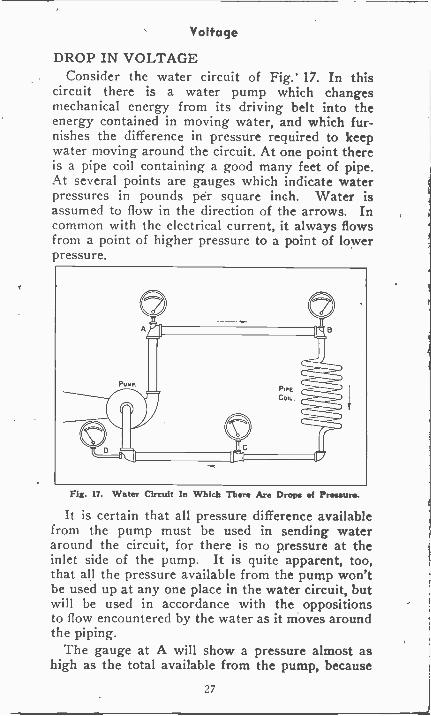
DROP IN VOLTAGEConsider the water circuit of Fig. 17. In this
circuit there is a water pump which changesmechanical energy from its driving belt into theenergy contained in moving water, and which fur-nishes the difference in pressure required to keepwater moving around the circuit. At one point thereis a pipe coil containing a good many feet of pipe.At several points are gauges which indicate waterpressures in pounds per square inch. Water isassumed to flow in the direction of the arrows. Incommon with the electrical current, it always flowsfrom a point of higher pressure to a point of lowerpressure.
Fig. 17. Water Circuit In Which There Are Drops of Pressure.
It is certain that all pressure difference availablefrom the pump must be used in sending wateraround the circuit, for there is no pressure at theinlet side of the pump. It is quite apparent, too,that all the pressure available from the pump won'tbe used up at any one place in the water circuit, butwill be used in accordance with the oppositionsto flow encountered by the water as it moves aroundthe piping.
The gauge at A will show a pressure almost ashigh as the total available from the pump, because
27
Voltage
it takes but little force or pressure to get waterfrom the pump to A. It takes some force or pres-sure to send water through the pipe from A to B,so the gauge at B shows a pressure a little lowerthan the one at A. The pressure at A must beenough to drive water from here all the rest of theway around the circuit and back to the pump, butthe pressure at B need be only enough to drivewater from this point back to the pump.
The coil in Fig. 17 is made of a long lengthof rather small pipe. It takes quite a bit of ouravailable pressure to send water through all thispipe, so the pressure remaining at C will be con-siderably less than we had at B. The pressureremaining at C must be enough to send water fromhere back to the pump, but no more. At D, thepump inlet, the pressure is zero.
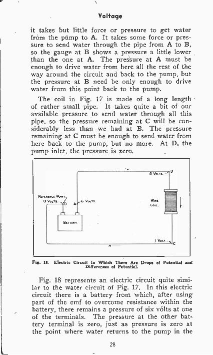
Fig. 16. Electric Circuit In Which There Are Drops of Potential andDifferences of Potential.
Fig. 18 represents an electric circuit quite simi-lar to the water circuit of Fig. 17. In this electriccircuit there is a battery from which, after usingpart of the emf to overcome resistance within thebattery, there remains a pressure of six volts at oneof the terminals. The pressure at the other bat-tery terminal is zero, just as pressure is zero atthe point where water returns to the pump in the
28
Voltage
water circuit. Therefore, the difference in pressurebetween the terminals is six volts.
The entire six volts is used up between A and Din the electric circuit, for we start out with sixvolts and end up with no volts. But, as with thewater circuit, all the pressure is not used up insending electricity through any one part of thecircuit, but rather it is used as required to over-come the resistance in various parts of the circuit.The greater the resistance in any section of the elec-tric circuit the more pressure must be used up inthat section to force electricity through its re-sistance.
In Fig. 18 we assume that it takes only one voltof pressure to overcome the resistance of the wirefrom A to B, but that in the long length of wire inthe coil it is necessary to use up four volts of pres-sure, which is the difference between the pressuresat B and C. The remaining one volt of pressuresends electricity through the wire from C back tothe battery.
The pressure in any electric circuit undergoesa continual drop as we progress around the circuitand use up the pressure in overcoming resistanceof different sections. The pressure is greatest atone side of the source and is least at the other side.
DIFFERENCE IN PRESSUREIt is the difference between the pressures at two
points in a circuit which causes current to flowfrom one point to the other. In Fig. 18 it is theentire pressure difference of the battery that causescurrent to flow through the entire circuit from A toD. Current flows from A to B because the pressureat A is higher than at B, it flows from B to C be-cause the pressure at B is higher than at C, andfrom C to D because the pressure at C is higherthan at D.
To determine the difference in electrical pressurebetween two points in a circuit, it is first of all nec-essary to establish a reference point.
29
Difference in Pressure
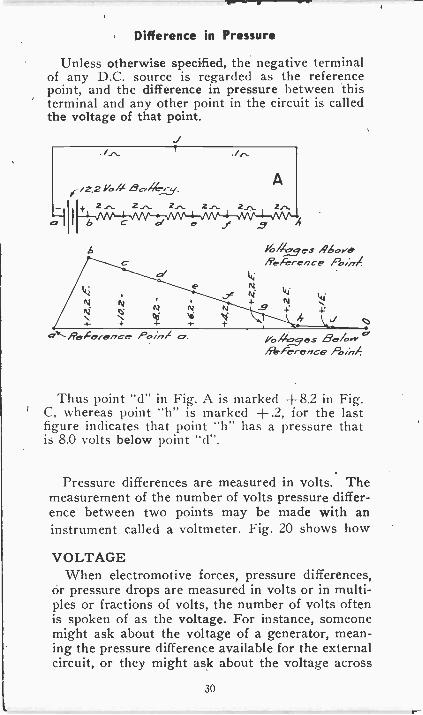
Unless otherwise specified, the negative terminalof any D.C. source is regarded as the referencepoint, and the difference in pressure between thisterminal and any other point in the circuit is calledthe voltage of that point.
Yo/7:_,L75.es ,4 -eReference P.int4
14i
Ni61
N 4b N N .9 4:b OIiieferenc-e /'o.n/ a. 1/o/Itae.s. Sc./orr
/%Ice'rence
Thus point "d" in Fig. A is marked +8.2 in Fig.C, whereas point "h" is marked +.2, for the lastfigure indicates that point "h" has a pressure thatis 8.0 volts below point "d".
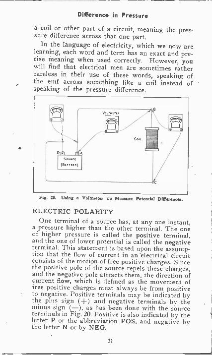
Pressure differences are measured in volts. Themeasurement of the number of volts pressure differ-ence between two points may be made with aninstrument called a voltmeter. Fig. 20 shows how
VOLTAGEWhen electromotive forces, pressure differences,
or pressure drops are measured in volts or in multi-ples or fractions of volts, the number of volts oftenis spoken of as the voltage. For instance, someonemight ask about the voltage of a generator, mean-ing the pressure difference available for the externalcircuit, or they might ask about the voltage across
30
Difference in Pressure
a coil or other part of a circuit, meaning the pres-sure difference across that one part.
In the language of electricity, which we now arelearning, each word and term has an exact and pre-cise meaning when used correctly. However, youwill find that electrical men are sometimes rathercareless in their use of these words, speaking ofthe emf across something like a coil instead ofspeaking of the pressure difference.
Fig. 20. Using a Voltmeter To Measure Potential Differences.
ELECTRIC POLARITYOne terminal of a source has, at any one instant,
a pressure higher than the other terminal. The oneof higher pressure is called the positive terminal,and the one of lower potential is called the negativeterminal. This statement is based upon the assump-tion that the flow of current in an 'electrical circuitconsists of the motion of free positive charges. Sincethe positive pole of the source repels these charges,and the negative pole attracts them, the direction ofcurrent flow, which is defined as the movement offree positive charges must always be from positiveto negative. Positive terminals may be indicated bythe plus sign (+) and negative terminals by theminus sign (-), as has been done with the sourceterminals in Fig. 20. Positive is also indicated by theletter P or the abbreviation POS, and negative bythe letter N or by NEG.
31
Difference in Pressure
Voltmeters and other meters have one terminalmarked positive and the other negative. In orderthat the meter may read correctly its positive termi-nal must be connected to the point of higher pres-sure and its negative terminal to the one of lowerpressure.
Because of pressure drops and differences in acircuit one point will have a pressure higher thananother point. The point of higher pressure is posi-tive with reference to the other one, which is nega-tive with reference to the first point. In Fig. 20the pressure becomes lower and lower as we pro-gress from A to D. Then point A is positive withreference to B, and B is negative with referenceto A. But because the pressure at B is higher thanat C, point B is positive with reference to C whilebeing negative with reference to A.
The words positive and negative, as just used,describe the polarity of points in an electric circuitwith reference to other points in the same circuit.
The whole mass of the earth or the ground us-ually is considered as having zero pressure or nopressure at all. Then we may speak of anythingwhose pressure is higher than that of the earth asbeing positive, and of anything whose pressure isless than that of the earth as being negative. Youmay wonder how we can have a pressure less thanzero, but this is explained by remembering that theearth's pressure. is only arbitrarily taken as zero,just as one certain point on the thermometer isarbitrarily considered zero. We may have pres-sures lower than the earth's zero pressure just as wemay have temperatures lower than zero on thethermometer. In electrical terminology, the termpotential is often used in the same sense as the wordpressure is here applied; thus the "difference inpressure" in volts and the "difference in potential"in volts mean one and the same thing. For purposesof simplification, the word pressure has been em-ployed in the foregoing material.
32
Resistance of Conductors
RESISTANCE OF CONDUCTORSSeveral times it has been mentioned that the re-
sistance of a conductor depends largely on the kindof material in the conductor. When talking aboutelectron flow in conductors we listed a number ofmaterials in the order of the freedom with whichelectrons pass through them. From our later dis-cussion of resistance it is evident that the material(silver) permitting the freest flow of current musthave the least resistance, and that materials per-mitting smaller rates of flow when a given differ-ence in pressure is applied to them, must havehigher resistances.
The resistance in ohms of a conductor is affectedby other things as well as by its material. Hereare the factors which determine resistance:
1. The material of which the conductor is made.
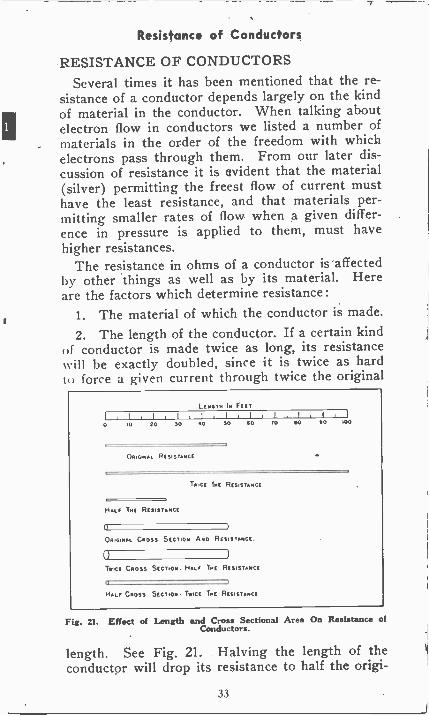
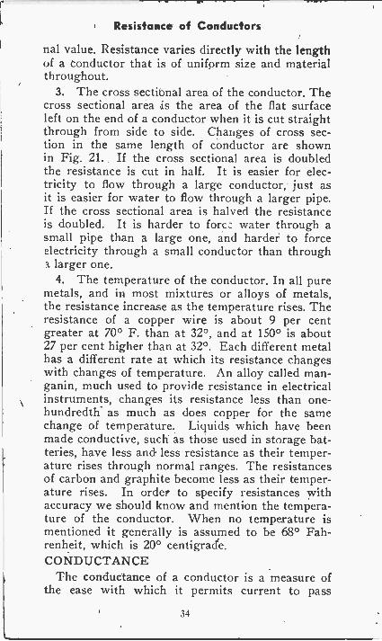
2. The length of the conductor. If a certain kindof conductor is made twice as long, its resistancexvill be exactly doubled, since it is twice as hardto force a given current through twice the original
LENGIN Is FELT
I 1,I I 1,11 I
0 .0 20 30 40 SO GO TO
02.454A. RES;STANCC
GO SO 100
TvoCE Trot RESISTANCE
HA., TGG Rasistaptct
(1
05.0.543 CROSS Stcnon Aso RESISTANCE
Twpct Caoss Stcrioel. HALF Toc RESISTANCE
HLr CROSS SECT,ON- U42 IKE RES.STANCE
Fig. 21. Effect of Length and Cross Sectional Area On Resistance ofConductors.
length. See Fig. 21. Halving the length of theconductor will drop its resistance to half the origi-
33
Resistance of Conductors
nal value. Resistance varies directly with the lengthof a Conductor that is of uniform size and materialthroughout.
3. The cross sectibnal area of the conductor. Thecross sectional area is the area of the flat surfaceleft on the end of a conductor when it is cut straightthrough from side to side. Changes of cross sec-tion in the same length of conductor are shownin Fig. 21. If the cross sectional area is doubledthe resistance is cut in half. It is easier for elec-tricity to flow through a large conductor, just asit is easier for water to flow through a larger pipe.If the cross sectional area is halved the resistanceis doubled. It is harder to fort.: water through asmall pipe than a large one, and harder to forceelectricity through a small conductor than througha larger one.
4. The temperature of the conductor. In all puremetals, and in most mixtures or alloys of metals,the resistance increase as the temperature rises. Theresistance of a copper wire is about 9 per centgreater at 70° F. than at 32°, and at 150° is about27 per cent higher than at 32°. Each different metalhas a different rate at which its resistance changeswith changes of temperature. An alloy called man-ganin, much used to provide resistance in electricalinstruments, changes its resistance less than one -
hundredth as much as does copper for the samechange of temperature. Liquids which have beenmade conductive, such as those used in storage bat-teries, have less and less resistance as their temper-ature rises through normal ranges. The resistancesof carbon and graphite become less as their temper-ature rises. In order to specify resistances withaccuracy we should know and mention the tempera-ture of the conductor. When no temperature ismentioned it generally is assumed to be 68° Fah-renheit, which is 20° centigrade.CONDUCTANCE
The conductance of a conductor is a measure ofthe ease with which it permits current to pass
34
Electrical Symbols
through it, as opposed to resistance which is ameasure of the opposition to current flow. The unitof conductance is the mho, which is ohm spelledbackward. The conductance in mhos is equal tothe reciprocal or the resistance in ohms. The re-ciprocal of a number is 1, divided by that number.Thus, the reciprocal of 10 is 1/10. If the resistanceof a conductor is 10 ohms its conductance is 1/10mho.
Nearly all our practical calculations are madewith resistance measured in ohms. Conductancesin mhos are seldom used.
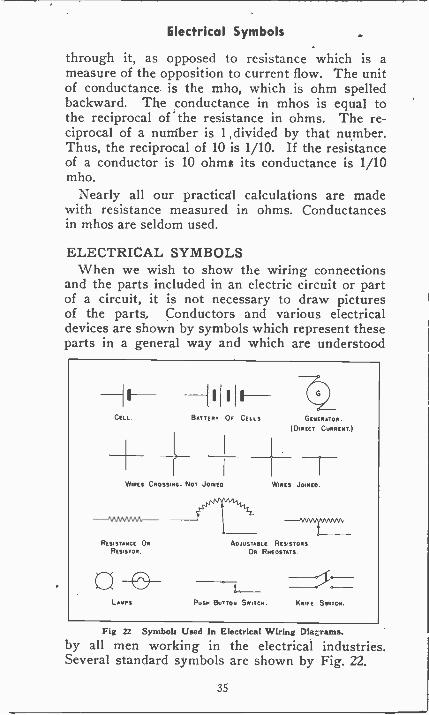
ELECTRICAL SYMBOLSWhen we wish to show the wiring connections
and the parts included in an electric circuit or partof a circuit, it is not necessary to draw picturesof the parts. Conductors and various electricaldevices are shown by symbols which represent theseparts in a general way and which are understood
Ca
WIRES
I F -BATTERY Of CELLS GENERATOR.
(DIRECT CURRENT.)
CROSSING- NOT JOINED
RESISTANCE ORRESISTOR
0LAISPS
WIRES JOINED.
ADJUSTASLE RESISTORS
OR RHEOSTATS.
Pusot BUTTON SW- IT-CH. KNIFE SWITCH.
Fig 22 Symbols Used In Electrical Wiring DiaLrams.
by all men working in the electrical industries.Several standard symbols are shown by Fig. 22.
35
Electrical Symbols
The cell represents a single dry cell or a singlecell of any other type which produces electromotiveforce from chemical action. Several cells togetherform a battery. The number of cell symbols drawnto represent the battery may or may not correspondto the number of cells actually in the battery to beshown. The long line of the cell symbol representsthe positive terminal and the short line the negativeterminal.
The generator symbol is marked "direct current"because it represents the kind of generator whichcauses electricity to flow always in the same di-rection around a circuit. This is the kind of flowwe have been considering and shall continue tostudy until taking up the subject of alternatingcurrent later on. Alternating current is a surg-ing back and forth of electricity in the conductors,moving one direction for a brief period and then inthe opposite direction for an equal period of time.
Wires which cross over each other without beingjoined together or in electrical contact may beshown in any of three ways. Electricity cannotflow from one to the other of wires which are notin actual contact, or which are separated by in-sulation as indicated in these symbols. If two ormore wires are in direct contact so that currentmay flow from one to the other at the point ofcontact, we show the joining by means of a smalldot at the junction.
If a large amount of resistance is concentratedinto a small space, as by winding much wire intoa compact coil, we may call the unit a resistanceor a resistor. The symbol for such concentratedresistance is a zig-zag line. Many resistors areso constructed that a brush or other movable con-tact point may be slid along the resistance wire,thus including between the contact and one end ofthe wire rno, e or less resistance or more or less ofthe total length of the wire. Such an arrange-ment provides an adjustable amount of resistancefor use in a circuit to limit the flow of current. An
36
Electrical Symbols
adjustable resistor may be called a rheostat. Thearrowhead in the symbols represents the movableor sliding contact point.
Switches, as you doubtless know, are devices inwhich metallic conductors may be convenientlybrought together so that current may flow throughthem and through a connected circuit, or which maybe separated so that they have between them theinsulation of air, which prevents flow of current.A push button switch is of the type used for doorbells. A knife switch opens and closes with a mo-tion like moving the blade of a jack knife. Theknife switch for which a symbol is shown has twoblades, that simultaneously opens or closes twoconductive current paths.
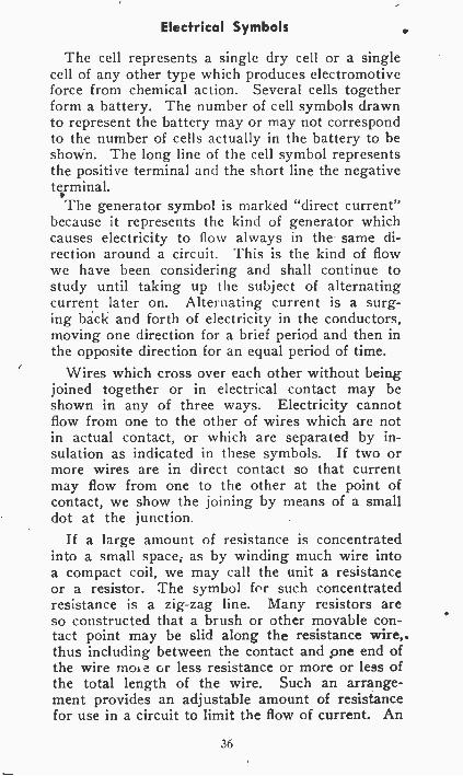
Fig. 23 is a diagram of an electric circuit show-ing how simple and easily understood are the con-nections and the paths for current when we usesymbols to represent the electrical devices. Referto the symbols of Fig. 22 and see how many of themyou can identify in Fig. 23. Fig. 23 shows twocoils whose symbols are not included in Fig. 22.
Fig 23 Wiring Diagram In Which Symbols Are Used.
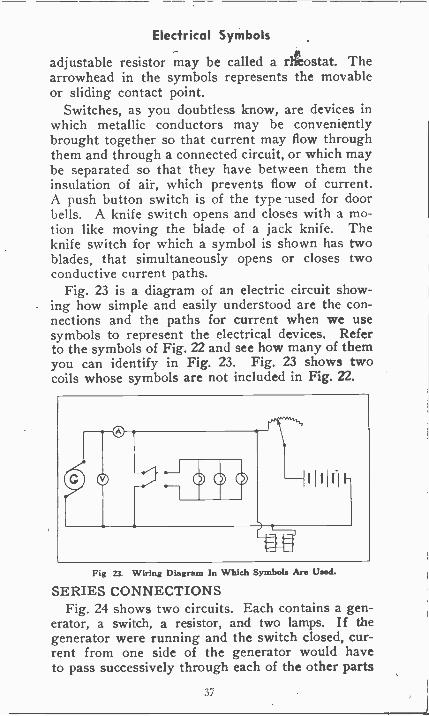
SERIES CONNECTIONSFig. 24 shows two circuits. Each contains a gen-
erator, a switch, a resistor, and two lamps. If thegenerator were running and the switch closed, cur-rent from one side of the generator would haveto pass successively through each of the other parts
37
Series Connections
before coming back to the generator. Furthermore,every bit of current that goes through the generator
Fig 24. Series Circuits.
must go also through every other part of the circuit.The current cannot divide at any point. All thecurrent that flows in any one part of the circuitmust flow also in every other part.
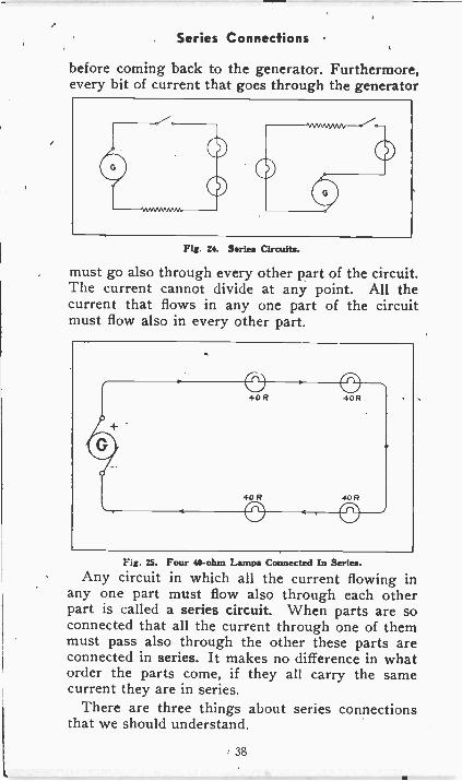
Fig. 25. Four 40 -ohm Lamps Connected In Series.
Any circuit in which all the current flowing inany one part must flow also through each otherpart is called a series circuit. When parts are soconnected that all the current through one of themmust pass also through the other these parts areconnected in series. It makes no difference in whatorder the parts come, if they all carry the samecurrent they are in series.
There are three things about series connectionsthat we should understand.
38
Series Connections
1. The current in amperes is the same in allparts connected in series. If the flow is five am-peres in any one part it must be five amperes inevery other part.
2. The total resistance in ohms of all the partsconnected in series is equal to the sum of theirseparate resistance in ohms. In Fig. 25 we have fourlamps in series. Each lamp has a resistance of 40ohms. Neglecting the very small resistance ofthe connecting wires, the total resistance of thiscircuit is 4 x 40, or is 160 ohms.
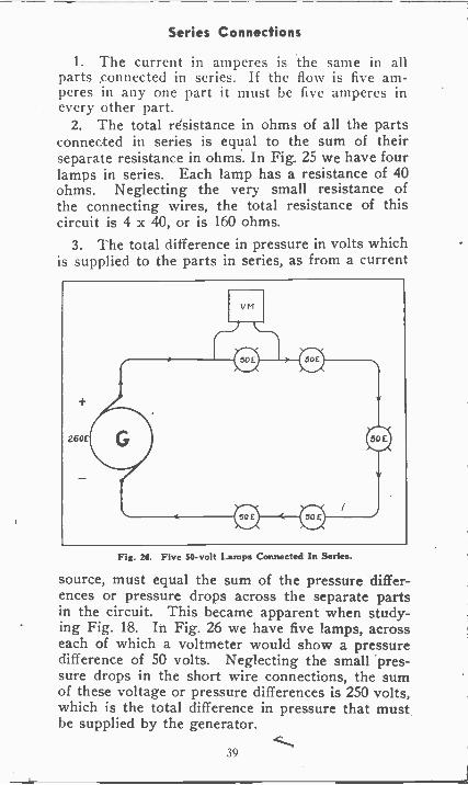
3. The total difference in pressure in volts whichis supplied to the parts in series, as from a current
Fig. 28. Five 50 -volt Lamps Connected In Series.
source, must equal the sum of the pressure differ-ences or pressure drops across the separate partsin the circuit. This became apparent when study-ing Fig. 18. In Fig. 26 we have five lamps, acrosseach of which a voltmeter would show a pressuredifference of 50 volts. Neglecting the small 'pres-sure drops in the short wire connections, the sumof these voltage or pressure differences is 250 volts,which is the total difference in pressure that mustbe supplied by the generator.
39
Relation of Current, Voltage and Resistance
RELATION OF CURRENT, VOLTAGEAND RESISTANCE
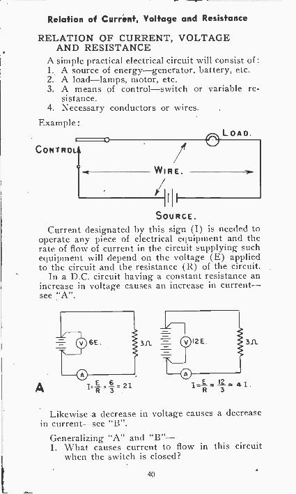
A simple practical electrical circuit will consist of :1. A source of energy-generator, battery, etc.2. A load-lamps, motor, etc.3. A means of control-switch or variable re-
sistance.4. Necessary conductors or wires.
Example:
CONTROL!,0
LOAD.
WIRE.
friii
SOURCE.
Current designated by this sign (I) is needed tooperate any piece of electrical equipment and therate of flow of current in the circuit supplying suchequipment will depend on the voltage (E) appliedto the circuit and the resistance (R) of the circuit.
In a D.C. circuit having a constant resistance anincrease in voltage causes an increase in current-see "A".
311
A
Likewise a decrease in voltage causes a decreasein current-see "B".
Generalizing "A" and "B"-1. What causes current to flow in this circuit
when the switch is closed?
40
Relation of Current, Voltage and Resistance
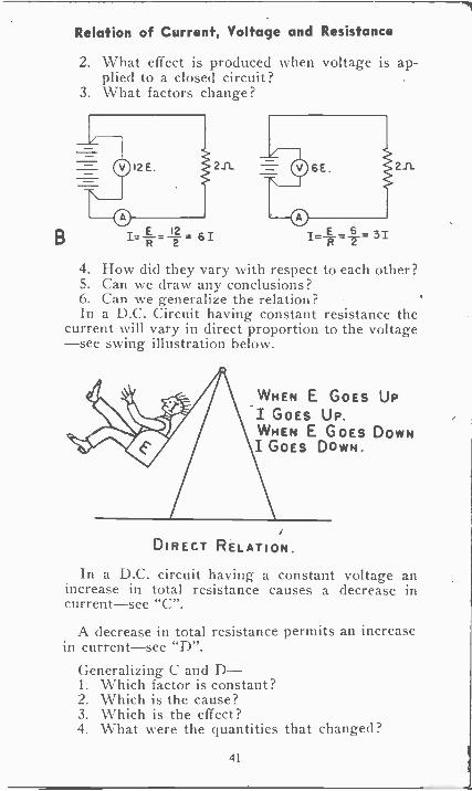
2. What effect is produced when voltage is ap-plied to a closed circuit?
3. What factors change?
2A
B I.. E 12---.-31- a 61R
.1..,.=E=--_ 31
-F1-
4. How did they vary with respect to each other?5. Can we draw any conclusions?6. Can we generalize the relation?In a D.C. Circuit having constant resistance the
current will vary in direct proportion to the voltage-see swing illustration below.
21L
WHEN E GOES UPI GOES UP.WHEN E GOES DOWNI GOES DOWN.
DIRECT RELATION.
In a D.C. circuit having a constant voltage anincrease in total resistance causes a decrease incurrent-see "C".
A decrease in total resistance permits an increasein current-see "D".
Generalizing C and D-1. Which factor is constant?2. Which is the cause?3. Which is the effect?4. What were the quantities that changed?
41
C
Relation of Current, Voltage and Resistance
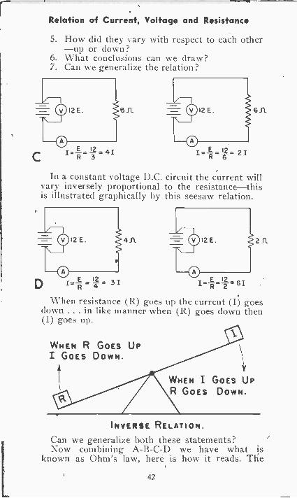
5. How did they vary with respect to each other-up or down?
6. What conclusions can we draw?7. Can we generalize the relation?
.311 6ft
In a constant voltage D.C. circuit the current willvary inversely proportional to the resistance-thisis illustrated graphically by this seesaw relation.
an
E 12I= -R=-2= 61
211
When resistance (R) goes up the current (I) goesdown .. . in like manner when (R) goes down then(I) goes up.
WHEN R GOES UPI GOES DOWN.
WHEN I GOES UPR GOES DOWN.
INVERSE RELATION.
Can we generalize both these statements?Now combining A -B -C -D we have what is
known as Ohm's law, here is how it reads. The
42
Ohms Law
current in any D.C. circuit is directly proportionalto the Voltage (E) and inversely proportional tothe resistance R).OHM'S LAW
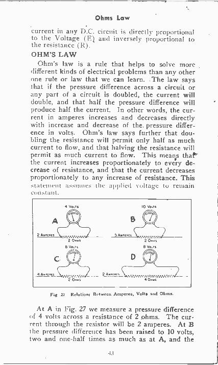
Ohm's law is a rule that helps to solve moredifferent kinds of electrical problems than any otherone rule or law that we can learn. The law saysthat if the pressure difference across a circuit orany part of a circuit is doubled, the current willdouble, and that half the pressure difference willproduce half the current. In other words, the cur-rent in amperes increases and decreases directlywith increase and decrease of the pressure differ-ence in volts. Ohm's law says further that dou-bling the resistance will permit only half as muchcurrent to flow, and that halving the resistance willpermit as much current to flow. This means that`the current increases proportionately to every de-crease of resistance, and that the current decreasesproportionately to any increase of resistance. Thistatement astinie:-, the applied voltage to remain
4A
4 VOLTS
2 0.rs8 Vo,Ts
2 ONles
2 Assets_
10 VOL'S
2 Omms
8 VOLTS
NANVVVNAMANVV4 0..as
Fig 27 Relations Between Amperes, Volts Ind Ohms.
At A in Fig. 27 we measure a pressure differenceof 4 volts across a resistance of 2 ohms. The cur-rent through the resistor will be 2 amperes. At Bthe pressure difference has been raised to 10 volts,two and one-half times as much as at A, and the
Ohms Law
current through the resistor now is 5 amperes,which is two and one-half times the original currentthrough the same amount of resistance.
At C in Fig. 27 the pressure difference across a2 -ohm resistance measures 8 volts. The current is4 amperes. At D the resistance has been increasedto 4 ohms, twice as much as at C, and now we havea current of only 2 amperes with the same pressuredifference. Doubling the resistance has cut the cur-rent to half.
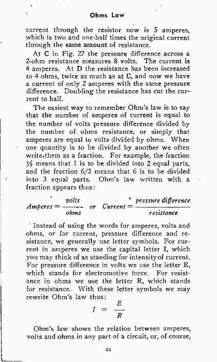
The easiest way to remember Ohm's law is to saythat the number of amperes of current is equal tothe number of volts pressure difference divided bythe number of ohms resistance, or simply thatamperes are equal to volts divided by ohms. Whenone quantity is to be divided by another we oftenwrite them as a fraction. For example, the fraction
means that 1 is to be divided into 2 equal parts,and the fraction 6/3 means that 6 is to be dividedinto 3 equal parts. Ohm's law written with afraction appears thus :
voltsAmperes -
ohmsor Current -
pressure difference
resistance
Instead of using the words for amperes, volts andohms, or for current, pressure difference and re-sistance, we generally use letter symbols. For cur-rent in amperes we use the capital letter I, whichyou may think of as standing for intensity of current.For pressure difference in volts we use the letter E,which stands for electromotive force. For resist-ance in ohms we use the letter R, which standsfor resistance. With these letter symbols we mayrewrite Ohm's law thus:
E
R
Ohm's law shows the relation between amperes,volts and ohms in any part of a circuit, or, of course,
44
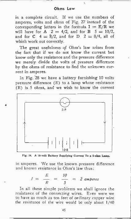
Ohms Law
in a complete circuit. If we use the numbers ofamperes, volts and ohms of Fig. 27 instead of thecorresponding letters in the formula I = E/R wewilt have for A 2 = 4/2, and for B 5 = 10/2,and for C 4 = 8/2, and for D 2 = 8/4, all ofwhich work out correctly.
The great usefulness of Ohm's law arises fromthe fact that if we do not know the current butknow only the resistance and the pressure differencewe merely divide the volts of pressure differenceby the ohms of resistance to find the unknown cur-rent in amperes.
In Fig. 28 we have a battery furnishing 10 voltspressure difference (E) to a lamp whose resistance(R) is 5 ohms, and we wish to know the current
5
IDE
Fig. 28. A 10 -volt Battery Supplying Current To a S -ohm Lamp.
in amperes. We use the known pressure differenceand known resistance in Ohm's law thus:
E 101 = - = - = 2 amperesR 5
In all these simple problems we shall ignore theresistance of the connecting wires. Even were weto have as much as ten feet of ordinary copper wirethe resistance of the wire would be only about 1/40
45
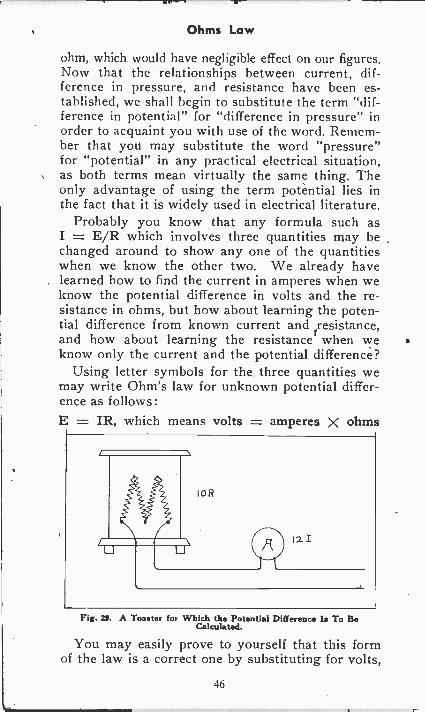
Ohms Law
ohm, which would have negligible effect on our figures.Now that the relationships between current, dif-ference in pressure, and resistance have been es-tablished, we shall begin to substitute the term "dif-ference in potential" for "difference in pressure" inorder to acquaint you with use of the word. Remem-ber that you may substitute the word "pressure"for "potential" in any practical electrical situation,as both terms mean virtually the same thing. Theonly advantage of using the term potential lies inthe fact that it is widely used in electrical literature.
Probably you know that any formula such asI = E/R which involves three quantities may bechanged around to show any one of the quantitieswhen we know the other two. We already havelearned how to find the current in amperes when weknow the potential difference in volts and the re-sistance in ohms, but how about learning the poten-tial difference from known current and resistance,and how about learning the resistance when weknow only the current and the potential difference?
Using letter symbols for the, three quantities wemay write Ohm's law for unknown potential differ-ence as follows:E = IR, which means volts = amperes X ohms
Fig. n. A Toaster for Which the Potential Difference Is To BeCalculated.
You may easily prove to yourself that this formof the law is a correct one by substituting for volts,
46
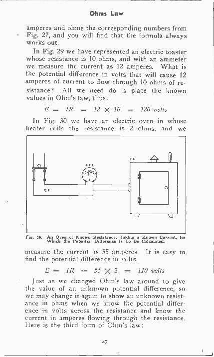
Ohms Law
amperes and ohms the corresponding numbers fromFig. 27, and you will find that the formula alwaysworks out.
In Fig. 29 we have represented an electric toasterwhose resistance is 10 ohms, and with an ammeterwe measure the current as 12 amperes. What isthe potential difference in volts that will cause 12amperes of current to flow through 10 ohms of re-sistance? All we need do is place the knownvalues in Ohm's law, thus :
E = IR = 12 X 10 = 120 voltsIn Fig. 30 we have an electric oven in whose
heater coils the resistance is 2 ohms, and we
Fig. 30. An Oven of Known Resistance, Taking a Known Current, forWhich the Potential Difference Is To Be Calculated.
measure the current as 55 amperes. It is easy tofind the potential difference in volts.
E = I R = 55 X 2 = 110 voltsJust as we changed Ohm's law around to give
the value of an unknown potential difference, sowe may change it again to show an unknown resist-ance in ohms when we know the potential differ-ence in volts across the resistance and know thecurrent in amperes flowing through the resistance.Here is the third form of Ohm's law:
47
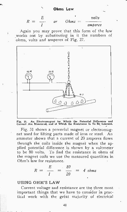
Ohms Law
ER = - or Ohms -I
volts
amperes
Again you may prove that this form of the law.works out by substituting in it the numbers ofohms, volts and amperes of Fig. 27.
Fig. 31. An Electromagnet for Which the Potential Difference andCurrent Are Measured, and of Which the Resistance Is To Be Learned.
Figs 31 shows a powerful magnet or electromag-net used for lifting parts made of iron or steel. Anammeter shows that a current of 20 amperes flowsthrough the coils inside the magnet when the ap-plied potential difference is shown by a voltmeterto be 80 volts. To find the resistance in ohms ofthe magnet coils we use the measured quantities inOhm's law for resistance.
R =E 80
1 20= 4 ohms
USING OHM'S LAWCurrent voltage and resistance are the three most
important things that we have to consider in prac-tical work with the great majority of electrical
48
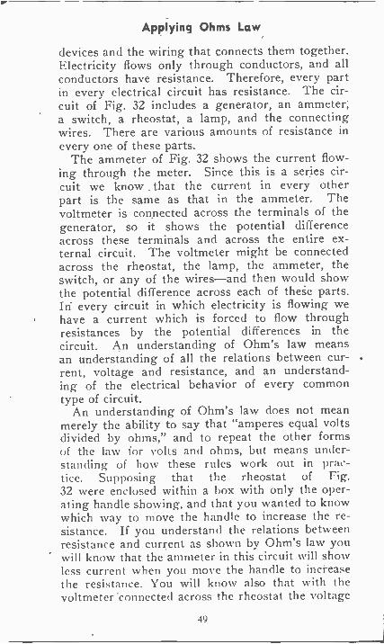
Applying Ohms Law
devices and the wiring that connects them together.Electricity flows only through conductors, and allconductors have resistance. Therefore, every partin every electrical circuit has resistance. The cir-cuit of Fig. 32 includes a generator, an ammeter,a switch, a rheostat, a lamp, and the connectingwires. There are various amounts of resistance inevery one of these parts.
The ammeter of Fig. 32 shows the current flow-ing through the meter. Since this is a series cir-cuit we know . that the current in every otherpart is the same as that in the ammeter. Thevoltmeter is connected across the terminals of thegenerator, so it shows the potential differenceacross these terminals and across the entire ex-ternal circuit. The voltmeter might be connectedacross the rheostat, the lamp, the ammeter, theswitch, or any of the wires-and then would showthe potential difference across each of theie parts.In every circuit in which electricity is flowing wehave a current which is forced to flow throughresistances by the potential differences in thecircuit. An understanding of Ohm's law meansan understanding of all the relations between cur-rent, voltage and resistance, and an understand-ing of the electrical behavior of every commontype of circuit.
An understanding of Ohm's law does not meanmerely the ability to say that "amperes equal voltsdivided by ohms," and to repeat the other formsof the law for volts and ohms, but means under-standing of how these rules work out in prac-tice. Supposing that the rheostat of Fig.32 were enclosed within a box with only the oper-ating handle showing, and that you wanted to knowwhich way to move the handle to increase the re-sistance. If you understand the relations betweenresistance and current as shown by Ohm's law youwill know that the ammeter in this circuit will showless current when you move the handle to increasethe resistance. You will know also that with thevoltmeter connected across the rheostat the voltage
49
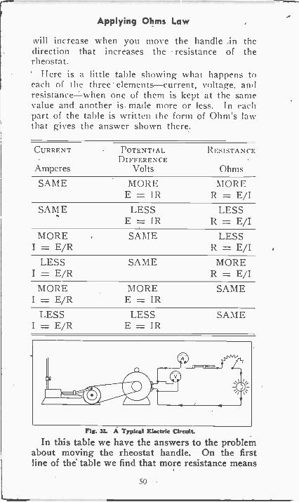
Applying Ohms Law
will increase when you move the handle in thedirection that increases the resistance of therheostat.
Here is a little table showing what happens toeach of the three elements-current, voltage, andresistancewhen one of them is kept at the samevalue and_ another is made more or less. In eachpart of the table is written the form of Ohm's lawthat gives the answer shown there.
CURRENT POTENTIAL RESISTANCEDIFFERENCE
Amperes Volts Ohms
SAME MORE MOR EE = 112 R = E/I
SAME LESS LESSE = IR R = E/I
MORE SAME LESSI = E/R R = E/I
LESSI = E/R
SAME MORER = E/I
MORE MOREI = E/R E = IR
SAME
LESSI = E/R
LESSE = IR
SAME
Fig. 32. A Typical Electric Circuit.
In this table we have the answers to the problemabout moving the rheostat handle. On the firstline of the table we find that more resistance means
511
Applying Ohms Law
more potential difference in volts is required ifthe current is to remain the same, and on the fourthline we find that more resistance means less cur-rent in amperes if the voltage remains the same.The formula R = E/I answers the questions be-cause if in it you use different values of volts (E)with the same value of amperes (I), you willfind out what happens to resistance. If you trydifferent values of amperes (I) with the samevalue for volts (E) you again will find out whathappens to resistance under these conditions.
Stipp(),ing )nu knim that a certain electricaldevice must have a current of six amperes to oper-ate correctly, but an ammeter shows the currentto be eight amperes. You can reduce the currentby changing either the potential difference in voltsor the resistance in ohms. The table shows thatless current will flow with more resistance and thesame voltage, or with less voltage p.nd the sameresistance. Ohm's law will answer 'thousands ofelectrical questions.
When Ohm first explained his law for the rela-tions of current, potential difference and resistancehe did not write something like I = E/R, but hestated that current varies directly with potentialdifference, and inversely with resistance, that po-tential difference varies as the product of currentand resistance, and that resistance varies directlywith potential difference and inversely with current.This is just a short way of saying all that is shownby our table. The three formulas by which we showOhm's law are merely convenient ways for work-ing our problems which involve certain numbers ofamperes, volts and ohms.
One of the easiest ways to remember all threeformulas for Ohm's law is to remember this ar-rangement of the letter symbols,
E
I X R
51
Applying Ohms Law
Supposing you want to know the value of E orvolts. Cover the E with the tip of your fingerand you see only I X R, which means that multi-plying the number of amperes (I) by the numberof ohms (R) will give the number of volts. Ifyou want to know the number of amperes justcover up I, the symbol for amperes, and you seeE over R, which means to divide the number ofvolts by the number of ohms. If you want to findthe number of ohms, cover up R, the symbol forohms, and you see E over I, which means to dividethe number of volts by the number of amperes.
It is necessary to understand the relations be-tween current, potential difference and resistanceas shown in the table, but this requires no memoriz-ing, only a little reasoning for each case. For in-stance, you can read the first line of the table thus :
With the SAME current there will be MORE po-tential difference with MORE resistance. All youneed do to figure this out for yourself is to re-flect that it certainly is going to take more potentialdifference or more force to send the same currentthrough more resistance. Stated in another way,if you have the same current and observe that morepotential difference is needed to maintain this cur-rent, it is certain that the resistance must haveincreased, because it takes more force to get thesame current through more resistance.
Just as we have analyzed the meaning of the firstline of the table, so you should check over eachof the other lines for yourself. You will find thatthe conclusions are just common sense in eachcase, that they merely state what you already knowabout the behavior of current, voltage and re-sistance.
PARALLEL CONNECTIONS
Fig. 33 shows a water circuit in which all thewater flowing through the pump P flows alsothrough the water wheel or water motor WW and
52
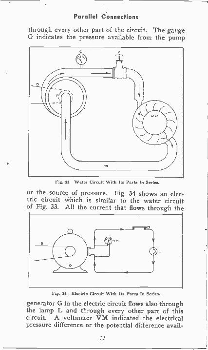
Parallel Connections
through every other part of the circuit. The gaugeG indicates the pressure available from the pump
Fig. 33. Water Circuit With Its Parts In Series.
or the source of pressure. Fig. 34 shows an elec-tric circuit which is similar to the water circuitof Fig. 33. All the current that flows through the
Fig. 34. Electric Circuit With Its Parts In Series.
generator G in the electric circuit flows also throughthe lamp L and through every other part of thiscircuit. A voltmeter VM indicated the electricalpressure difference or the potential difference avail -
53
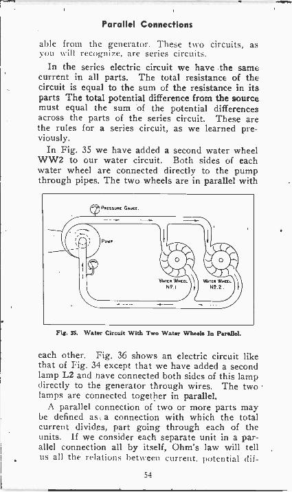
Parallel Connections
able from the generator. These two circuits, asyou will recognize, are series circuits.
In the series electric circuit we have the samecurrent in all parts. The total resistance of thecircuit is equal to the sum of the resistance in itsparts The total potential difference from the sourcemust equal the sum of the potential differencesacross the parts of the series circuit. These arethe rules for a series circuit, as we learned pre-viously.
In Fig. 35 we have added a second water wheelWW2 to our water circuit. Both sides of eachwater wheel are connected directly to the pumpthrough pipes. The two wheels are in parallel with
Fig. 35. Water Circuit With Two Water Wheels In Parallel.
each other. Fig. 36 shows an electric circuit likethat of Fig. 34 except that we have added a secondlamp L2 and nave connected both sides of this lampdirectly to the generator through wires. The twolamps are connected together in parallel.
A parallel connection of two or more parts maybe defined as a connection with which the totalcurrent divides, part going through each of theunits. If we consider each separate unit in a par-allel connection all by itself, Ohm's law will tellus all the relations between current, potential clif-
54
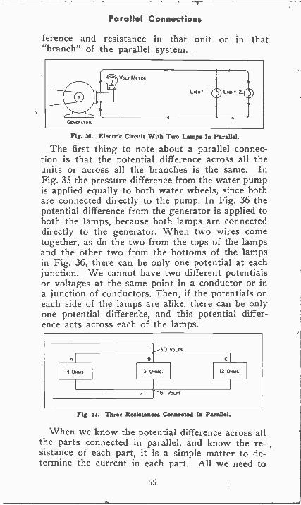
Parallel Connections
ference and resistance in that unit or in that"branch" of the parallel system.
uOGENERATOR.
VoLT METER
LIGHT I LIGHT 2
Fig. 36. Electric Circuit With Two Lamps In Parallel.
The first thing to note about a parallel connec-tion is that the potential difference across all theunits or across all the branches is the same. InFig. 35 the pressure difference from the water pumpis applied equally to both water wheels, since bothare connected directly to the pump. In Fig. 36 thepotential difference from the generator is applied toboth the lamps, because both lamps are connecteddirectly to the generator. When two wires cometogether, as do the two from the tops of the lampsand the other two from the bottoms of the lampsin Fig. 36, there can be only one potential at eachjunction. We cannot have two different potentialsor voltages at the same point in a conductor or ina junction of conductors. Then, if the potentials oneach side of the lamps are alike, there can be onlyone potential difference, and this potential differ-ence acts across each of the lamps.
A
4 Omus
VOLTS
3 OHMS. 12 Oums.
6 VOLTS
Fig 37. Three Resistances Connected In Parallel.
When we know the potential difference across allthe parts connected in parallel, and know the re- ,sistance of each part, it is a simple matter to de-termine the current in each part. All we need to
55
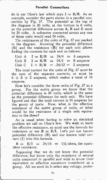
Parallel Connections
do is use Ohm's law which says I = E/R. As anexample, consider the parts shown in a parallel con-nection by Fig. 37. The potential at the top ofthe diagram is 30 volts, at the bottom is 6 volts,so the potential difference across A, B and C mustbe 24 volts. A voltmeter connected across any oneof these units would read 24 volts.
The resistances of the units of Fig. 37 are markedin the diagram. Knowing the potential difference(E) and the resistance (R) for each unit allowsfinding the currents for each unit as follows :
Unit A I = E/R = 24/4 = 6 amperesUnit B I = E/R = 24/3 = 8 amperesUnit C I = E/R = 24/12 = 2 amperesThe total current for the units of Fig. 37 must be
the sum of the separate currents, or must be6 + 8 + 2 amperes, which makes a total of 16amperes.
Now let's consider the three units of Fig. 37 as agroup. For the entire group we know that thepotential difference is 24 volts, which is the sameas the potential difference for each unit. We havefigured out that the total current is 16 amperes forthe group of parts. Now, what is the effectiveresistance of the entire group of units, or whatwould be the resistance of a single unit equiva-lent to the three?
As is usual when having to solve an electricalproblem we call on Ohm's law. We wish to learnthe effective resistance, so must use the formula forresistance or use R = E/I. Let's put our knownpotential difference (E) and our known total cur-rent (I) into this formula.
R = E/I = 24/16 = 1% ohms, the equiv-alent resistance.
Supposing that we do not know the potentialdifference, but know only the resistance of severalunits connected in parallel and wish to know theirequivalent or effective resistance considered as agroup. All we need do is select any voltage, prefer -
56
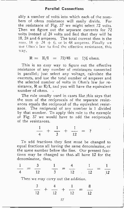
Parallel Connections
ably a number of volts into which each of the num-bers of ohms resistance will easily divide. Forthe resistance of Fig. 37 we might select 72 volts.Then we figure out the separate currents for 72volts instead of 24 volts and find that they will be18. 24 and 6 amperes. The total current then is thesum. 18 ± 24 6. or 'is 48 amperes. Finally weuse (_)tun's law to find the effective resistance, thisway,
R = E/I = 72/48 = 1% ohms.This is an easy way to figure out the effective
resistance of any number of resistances connectedin parallel; just select any voltage, calculate thecurrents, and use the total number of amperes andthe selected number of volts in Ohm's law for re-sistance, R = E/I, and you will have the equivalentnumber of ohms.
The rule usually used in cases like .this says thatthe sum of the reciprocals of the separate resist-ances equals the reciprocal of the equivalent resist-ance. The reciprocal of any number is 1 dividedby that number. To apply this rule to the exampleof Fig. 37 we would have to add the reciprocalsof the resistances.
4 3 12
To add fractions they first must be changed toequal fractions all having the same denominator, orthe same number below the line. Our present frac-tions may be changed so that. all have 12 for thedenominator, thus,
1 3 1 4 1 1
4 12 3 12 12 12
Then we may carry out the addition.
3 4 1 8
12 12 12 12
57
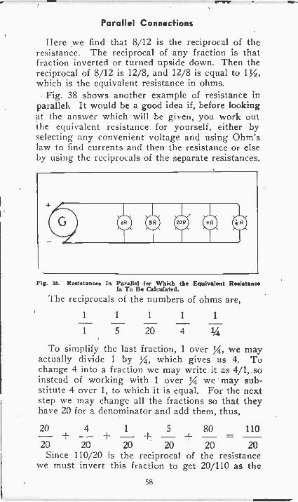
Parallel Connections
Here we find that 8/12 is the reciprocal of theresistance. The reciprocal of any fraction is thatfraction inverted or turned upside down. Then thereciprocal of 8/12 is 12/8, and 12/8 is equal to 1Y2,which is the equivalent resistance in ohms.
Fig. 38 shows another example of resistance inparallel. It would be a good idea if, before lookingat the answer which will be given, you work outthe equivalent resistance for yourself, either byselecting any convenient' voltage and using Ohm'slaw to find currents and then the resistance or elseby using the reciprocals of the separate resistances.
IR 3R 0 0
Fig. 38. Resistances In Parallel for Which the Equivalent ResistanceIs To Be Calculated.
The reciprocals of the numbers of ohms are,
1 1 1 1 1
1 5 20 4 1/4.
To simplify the last fraction, 1 over g, we mayactually divide 1 by yt, which gives us 4. Tochange 4 into a fraction we may write it as 4/1, soinstead of working with 1 over 1/4. we may sub-stitute 4 over 1, to which it is equal. For the nextstep we may change all the fractions so that theyhave 20 for a denominator and add them, thus,
20 4 1 5 80 110- + - + - + - + _ =20 20 20 20 20 20Since 110/20 is the reciprocal of the resistance
we must invert this fraction to get 20/110 as the58
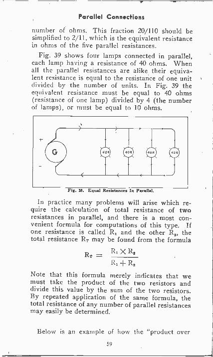
Parallel Connections
number of ohms. This fraction 20/110 should besimplified to 2/11, which is the equivalent resistancein ohms of the five parallel resistances.
Fig. 39 shows four lamps connected in parallel,each lamp having a resistance of 40 ohms. Whenall the parallel resistances are alike their equiva-lent resistance is equal to the resistance of one unitdivided by the number of units. In Fig. 39 theequivalent resistance must be equal to 40 ohms(resistance of one lamp) divided by 4 (the numberof lamps), or must be equal to 10 ohms.
Fig. Sg. Equal Resistances In Parallel.
In practice many problems will arise which re-quire the calculation of total resistance of tworesistances in parallel, and there is a most con-venient formula for computations of this type. Ifone resistance is called Ri and the other 122, thetotal resistance RT may be found from the formula
R, X R2RT
R1 + R2
Note that this formula merely indicates that wemust take the product of the two resistors anddivide this value by the sum of the two resistors.By repeated application of the same formula, thetotal resistance of any number of parallel resistancesmay easily be determined.
Below is an example of how the "product over
59
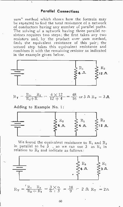
Parallel Connections
sum" method which shows how the formula maybe repeated to find the total resistance of a networkof conductors having any number of parallel paths.The solving of a network having three parallel re-sistors requires two steps; the first takes any tworesistors and, by the product over sum method,finds the equivalent resistance of this pair; thesecond step takes this equivalent resistance andcombines it with the remaining resistor as indicatedin the example given below.
RI4
R2
12 _ft
R1- R2 4 X 12 48 - -R T R_ -{-R 12 4 16 1(1. = 3 A
Adding to Example No. 1 :
R3
6 _ft_ 12 IL
We found the equivalent resistance to R1 and R2in parallel to be 3 , so we can use 3 as R1 inrelation to R3 and indicate as follows :
R3 iRl6 _ft 3 _fL
R1 R3 3 X 0 182 ITT 2 n.RT R3 R1 6 + 3 9
60
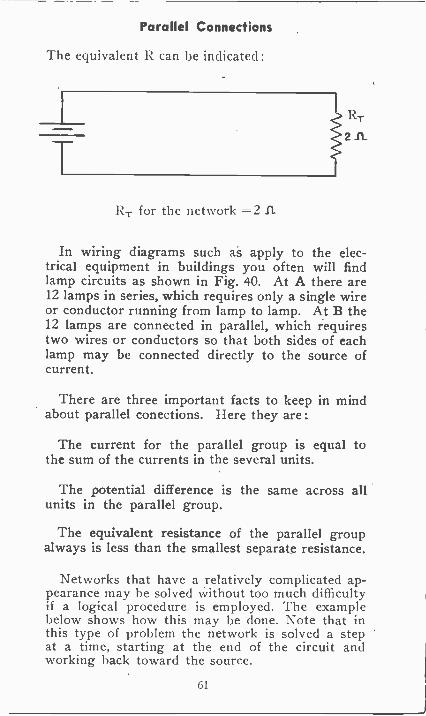
Parallel Connections
The equivalent R can be indicated:
RT
2A
RT for the network =2 LI
In wiring diagrams such as apply to the elec-trical equipment in buildings you often will findlamp circuits as shown in Fig. 40. At A there are12 lamps in series, which requires only a single wireor conductor running from lamp to lamp. At B the12 lamps are connected in parallel, which requirestwo wires or conductors so that both sides of eachlamp may be connected directly to the source ofcurrent.
There are three important facts to keep in mindabout parallel conections. Here they are :
The current for the parallel group is equal tothe sum of the currents in the several units.
The potential difference is the same across allunits in the parallel group.
The equivalent resistance of the parallel groupalways is less than the smallest separate resistance.
Networks that have a relatively complicated ap-pearance may be solved without too much difficultyif a logical procedure is employed. The examplebelow shows how this may be done. Note that inthis type of problem the network is solved a stepat a time, starting at the end of the circuit andworking back toward the source.
61
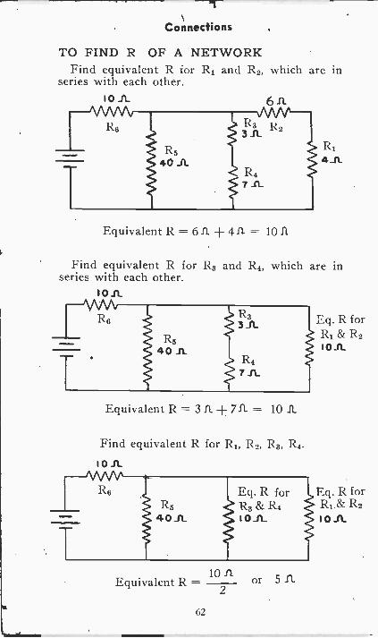
Connections
TO FIND R OF A NETWORKFind equivalent R for R1 and R2, which are in
series with each other.
R14_11
Equivalent R = 611 ± 4I1- = 1011
Find equivalent R for R3 and R4, which are inseries with each other.
I 0 11.
Eq. R forR1& R2
0 1 L
Equivalent R = 3 11 711- = 10 11
Find equivalent R for RI, R2, R3, R4.
I 0 IL
Eq. R forR1& R2I 0 -n-
10Equivalent R = or 5 IL
2
62
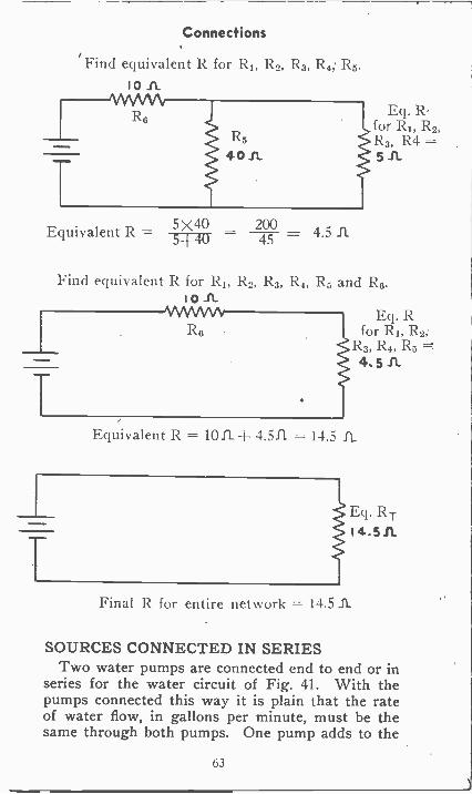
Connections
Find equivalent R for Ri, R2, R3, R4, R5.10
Eq. R -for RI, R2,R3, R4 =-
5 A
Equivalent R 5%00 -20045 4.5 A
Find equivalent R for RI, R2, R3, R4, R5 and R6.I 0 A
WNvR6
Eq. Rfor RI, R2,
R3, R4, R5 =-
4. 5 IL
Equivalent R = 10IL 4.5.ft = 14.5 IL
Eq. RTI4.5A
Final R for entire network = 14.51L
SOURCES CONNECTED IN SERIESTwo water pumps are connected end to end or in
series for the water circuit of Fig. 41. With thepumps connected this way it is plain that the rateof water flow, in gallons per minute, must be thesame through both pumps. One pump adds to the
63
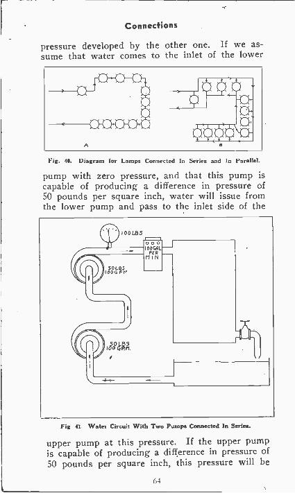
Connections
pressure developed by the other one. If we as-sume that water comes to the inlet of the lower
A
Fig. 40. Diagram for Lamps Connected In Series and In Parallel.
pump with zero pressure, and that this pump iscapable of producing a difference in pressure of50 pounds per square inch, water will issue fromthe lower pump and pass to the inlet side of the
Fig 41 Water Circuit With Two Pumps Connected In Series.
upper pump at this pressure. If the upper pumpis capable of producing a difference in pressure of50 pounds per square inch, this pressure will be
1)4
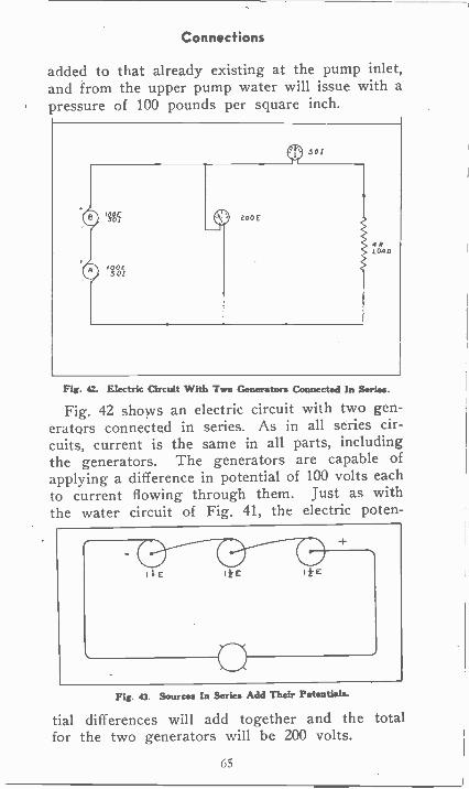
Connections
added to that already existing at the pump inlet,and from the upper pump water will issue with apressure of 100 pounds per square inch.
Fir. 42. Electric Circuit With Two Generators In Series.
Fig. 42 shows an electric circuit with two gen-eratqrs connected in series. As in all series cir-cuits, current is the same in all parts, includingthe generators. The generators are capable ofapplying a difference in potential of 100 volts eachto current flowing through them. Just as withthe water circuit of Fig. 41, the electric poten-
Fig 43. Sources In Series Add Their Potentials.
tial differences will add together and the totalfor the two generators will be 200 volts.
65
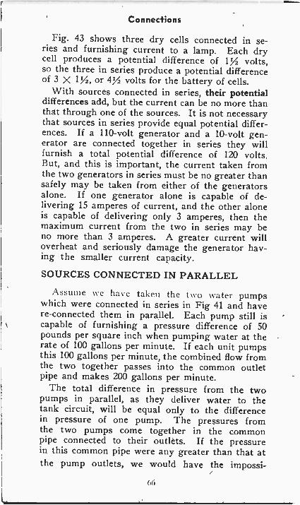
Connections
Fig. 43 shows three dry cells connected in se-ries and furnishing current to a lamp. Each drycell produces a potential difference of 1% volts,so the three in series produce a potential differenceof 3 X 172, or 472 volts for the battery of cells.
With sources connected in series, their potentialdifferences add, but the current can be no more thanthat through one of the sources. It is not necessarythat sources in series provide equal potential differ-ences. If a 110 -volt generator and a 10 -volt gen-erator are connected together in series they willfurnish a total potential difference of 120 volts.But, and this is important, the current taken fromthe two generators in series must be no greater thansafely may be taken from either of the generatorsalone. If one generator alone is capable of de-livering 15 amperes of current, and the other aloneis capable of delivering only 3 amperes, then themaximum current from the two in series may beno more than 3 amperes. A greater current willoverheat and seriously damage the generator hav-ing the smaller current capacity.
SOURCES CONNECTED IN PARALLEL
e have taken the t\ a water pumpswhich were connected in series in Fig 41 and havere -connected them in parallel. Each pump still iscapable of furnishing a pressure difference of 50pounds per square inch when pumping water at therate of 100 gallons per minute. If each unit pumpsthis 100 gallons per minute, the combined flow fromthe two together passes into the common outletpipe and makes 200 gallons per minute.
The total difference in pressure from the twopumps in parallel, as they deliver water to thetank circuit, will be equal only to the differencein pressure of one pump. The pressures fromthe two pumps come together in the commonpipe connected to their outlets. If the pressurein this common pipe were any greater than that atthe pump outlets, we would have the impossi-
66
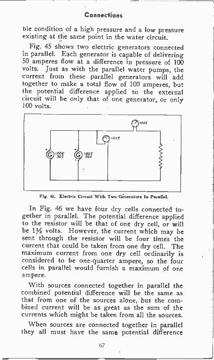
Connections
ble condition of a high pressure and a low pressureexisting at the same point in the water circuit.
Fig. 45 shows two electric generators connectedin parallel. Each generator is capable of delivering50 amperes flow at a difference in pressure of 100volts. Just as with the parallel water pumps, thecurrent from these parallel generators will addtogether to make a total flow of 100 amperes, butthe potential difference applied to the externalcircuit will be only that of one generator, or only100 volts.
Fig. 45. Electric Circuit With Two Generators In Parallel.
In Fig. 46 we have four dry cells connected to-gether in parallel. The potential difference appliedto the resistor will be that of one dry cell, or willbe 1% volts. However, the current which may besent through the resistor will be four times thecurrent that could be taken from one dry cell. Themaximum current from one dry cell ordinarily isconsidered to be one -quarter ampere, so the fourcells in parallel would furnish a maximum of oneampere.
With sources connected together in parallel thecombined potential difference will be the same asthat from one of the sources alone, but the com-bined current will be as great as the sum of thecurrents which might be taken from all the sources.
When sources are connected together in parallelthey all must have the same potential difference
67
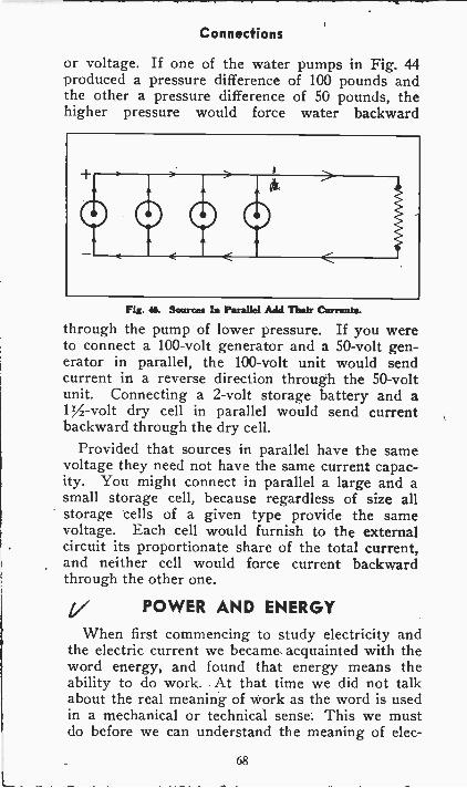
Connections
or voltage. If one of the water pumps in Fig. 44produced a pressure difference of 100 pounds andthe other a pressure difference of 50 pounds, thehigher pressure would force water backward
O 0 0Fit. IL Sources In Parallel Add Thar Currants.
through the pump of lower pressure. If you wereto connect a 100 -volt generator and a 50 -volt gen-erator in parallel, the 100 -volt unit would sendcurrent in a reverse direction through the 50 -voltunit. Connecting a 2 -volt storage battery and a1Y2 -volt dry cell in parallel would send currentbackward through the dry cell.
Provided that sources in parallel have the samevoltage they need not have the same current capac-ity. You might connect in parallel a large and asmall storage cell, because regardless of size allstorage cells of a given type provide the samevoltage. Each cell would furnish to the externalcircuit its proportionate share of the total current,and neither cell would force current backwardthrough the other one.
POWER AND ENERGY
When first commencing to study electricity andthe electric current we became acquainted with theword energy, and found that energy means theability to do work. At that time we did not talkabout the real meaning of work as the word is usedin a mechanical or technical sense. This we mustdo before we can understand the meaning of elec-
68
Power and Energy
trical power and power measurements.A common definition says that mechanical work
is done when any kind of energy is used to producemotion in a body formerly stationary, or to increasethe rate of motion of a body, or to slow down itsrate of motion. For example, you use muscularenergy when you lift a stone from the floor onto abench, and you do work. Were the stone too heavyfor you to lift you would have done no mechanicalwork no matter how hard you tried, for you wouldhave caused neither motion nor change of the rateof motion in the stone. This latter statement showshow different may be the everyday and the techni-cal uses of a word. Most people would say that youmight do a lot of work in trying to lift a stone tooheavy to move but the engineer would say that youhad done no mechanical work.
The most generally used unit of work is thefoot-pound. One foot-pound of work is done whena mass (which us usually call a weight) of onepound is lifted one foot against the force of gravity.The total amount of work done is equal to thenumber of feet of motion multiplied by the numberof pounds moved. If the stone we talked about hada mass (which is usually called a weight) of onethrough a distance of five feet you would have done20 times 5, or 100 foot-pounds of work.
Whether you did all the moving of the stone atone time or whether you lifted it through one footduring each hour for five hours the amount of workwould have been the same, because work involvesonly the mass moved and the distance throughwhich it is moved. Time doesn't enter into thematter of mechanical work.
MECHANICAL POWERPower is the rate of doing work. Supposing you
lifted the 20 -pound stone through the distance offive feet in one second. You would have done 100foot-pounds of work in one second, and would haveworked at a rate of 100 foot-pounds per second.
69
Power and Energy
Your power rate would have been 100 foot-poundsper second. Power involves work and time. Oneof the units in which power may be measured is"foot-pounds per second". Power is equal to thetotal amount of work divided by the time taken todo the work. It is assumed that the work is beingdone at a uniform or constant rate, at least duringthe period of time measured.
Instead of taking one second to lift the stonesupposing you took two seconds. Then your powerrate would be 100 foot-pounds per two seconds, oronly 50 foot-pounds per second. Taking twice asmuch time means half the power when the work isthe same. If you took four seconds to lift the weightthe power rate would he 100 foot-pounds per fourseconds, or only 25 foot-pounds per second.
The foot-pound per second is a unit too small tohe used in practise. Alechanical poorer most oftenis measured in the unit called a horsepower. Onehorsepower is the power rate corresponding to 550foot-pounds per second. Since there are 60 secondsin a minute, one horsepower corresponds also to550 times 60, or to 33,000 foot-pounds per minute.
An electric power at the rate of one horsepowerwould be capable of raising a weight of 33,000pounds through a distance of one foot in oneminute. At the same rate of one horsepower themotor would lift during one minute any number ofpounds through a distance such that the poundstimes the number of feet equalled 33,000.
ELECTRIC POWERIn order that the electric motor might continue
working at the rate of one horsepower we wouldhave to send electric current through the motor at acertain number of amperes when the pressure dif-ference across the motor terminals was some certainnumber of volts. The number of amperes and thenumber of volts would have to be such that multi-plied together they would equal 746. We now needa unit of electric power to describe this product of
70
Power and Energy
amperes and volts. Ordinarily we use a unit calledthe watt. One watt is the power produced by a cur-rent of one ampere when the pressure difference isone volt. We could use for our unit of electricpower the volt-ampere, meaning the product ofvolts and amperes which produce the power. Thevolt-ampere actually is used as a unit of power insome cases, which we shall investigate later on.
The total number of watts of power is equal tothe number of amperes of current multiplied by thenumber of volts pressure difference, both with ref-erence to the device in which power is being pro-duced. In a preceding paragraph we said that thenumber of amperes times the number of volts musthe 74() to produce one horsepower. Then we maysay that -74() watts of electric power is equivalentto one mechanical horsepower.
The symbol for electric power in watts is \V. Wemay use this power symbol together with E forvolts and I for amperes to make a power formula,thus,
W = E X IPower in watts = volts X amperes.
With this formula we may learn the number ofwatts of power when we know the number of voltspressure difference and the number of amperes cur-rent. With two more formulas we may learn thenumber of volts when knowing watts and amperes,and the number of amperes when knowing wattsand volts. Here are the formulas:
E =1
I =E
Volts -watts
Amperes =
amperes
watts
volts
Here are three typical problems in which we usethe three formulas relating to power in watts :
71
Power and Energy
With an ameter in series you find that an electricflatiron is carrying 6 amperes while a voltmetershows that the voltage difference across the connec-tions to the iron is 120 volts. We may us theformula W = ExI to find the power in watts beingused to heat the iron.
W=E X I W= 120 X 6 = 720 wattsSupposing you use an ammeter to measure the
current in a lamp as 1% or 1.5 amperes and findthat the lamp is marked as requiring 150 watts.What is the voltage difference at the lamp terminals.To find the number of volts we use the formula,E = W/I.
W 150E = = 100 volts
I 1.5
In this example you are assuming that the lampactually is using power at the rate of 150 watts. Ofcourse, if the actual power is more or less than therating of the lamp the number of volts shown bythe formula will not be exactly correct.
If the 150 -watt lamp were marked with its operat-ing voltage you could use the formua I= W/E tofind the normal current in amperes for this lamp.Say that the lamp is marked as requiring 120 volts.The formula would be used thus :
W 150 5I - -
120 4= 11/4, amperes
POWER AND HEATWhen an electric current is forced to flow in a
resistance, such as in the resistance of the heatingelement of an electric range, the rate at which heatis produced depends on the current in amperes andthe resistance in ohms. The rate of heat productiondepends also on the power being used in the re-sistance, this power being measured in watts. Therelation between power in watts, current in
72
Power and Energy
amperes, and pressure difference in volts for elec-trical devices in which there is heating is an impor-tant one, and we find that we frequently need aformula which will give the number of watts ofpower when we know the current and the resistance.
Our first power formula says that W = E X I,or, Watts = volts X amperes.
Ohm's law for pressure difference says thatE = I X R, or, Volts = amperes X ohms.
Instead of using "volts" in the power formulalet's use the equivalent of volts, which, from Ohm'slaw, we know 'to be "amperes x ohms". Making thissubstitution gives a new power formula, like this:
Watts = amperes X ohms X amperesor IXRXI
In this power formula we have only amperes andohms, we have gotten rid of the volts. Let's use theformula to learn the power in watts being used ina resistance of 10 ohms when the current is 5
amperes.Watts = IXRXI = 5X 10.X 5= 250 wattsInstead of writing this formula as I X R X I, we
might write it as IX I X R, which would give thesame result. When we multiply a quantity by itself,as I X I, we usually say that the quantity is squared.Instead of writing I X I we would write 12, whichmeans the same thing. Then our new powerformula becomes W = I2R.
You will find as we proceed with our study ofelectrical apparatus that this formula, W = I2R, isone of the most useful in our whole collection. Italways will tell us the number of watts of powerused in producing heat in a resistance.
ELECTRIC ENERGY.The total available energy which may be changed
into work, or which will do work, must be ameasure of the total amount of work that can bedone with that particular source of energy, such as
73
Power and Energy
a battery for example. If less than the total avail-able energy does work, then the amount of energyactually used must correspond to the amount ofwork actually done. Energy and work are so closelyrelated that we use the same units of measurementfor both. For instance, the foot-pound is a unit ofwork and also is a unit of energy which may dowork.
The foot-pound is a unit of mechanical energy orwork. The foot-pound per second and the horse-power are units of mechanical power. We alreadyhave become acquainted with a unit for electricpower, the watt, but so far we have no unit in whichto measure electric energy.
Our unit of mechanical energy or work, the foot-pound, measures a total quantity of work, such asthe work done in lifting the 20 -pound stone ontothe bench. The foot-pound does not measure a rateof working-, or a power rate, but measures a definitequantity of work. To have a unit of electrical energy
sometotal quantity and not a rate of working. Such aunit is the watt-hour.
One watt-hour of electric energy is the quantityof energy used with a power rate of one watt whenthis rate continues for one hour. That is, the watt-hours of energy are equal to the number of wattsmultiplied by the number of hours during whichpower is used at this rate. A 60 -watt electric lampuses energy at the rate of 60 watts SO long as it islighted to normal brilliancy. But the total quantityof energy used by the lamp depends also on thetotal length of time it remains lighted. If the 60 -watt lamp is kept lighted for 10 hours it will haveused 60 x 10, or 600 watt-hours of electric energy.
Just as we use the kilowatt instead of the wattfor measuring large powers, so we use the kilowatt-hour, abbreviated kwhr, for measuring large quanti-ties of electric energy. Most bills for electric lightand power are rendered in kilowatt-hours. It is thetotal quantity of energy that you use that is the
74
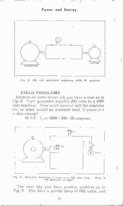
Power and Energy
GE,,ERATOR
Fig. 8. 200 volt generator supplying 4000 W machine.
FIELD PROBLEMSSuppose on some future job you have a case as in
Fig. 8. Your generator supplies 200 volts to a 4000watt machine. l low much currunt will the machineuse, or what should an ammeter read, if connectedin this circuit?
W F. 1, e.r 4000 200-20 amperes.
Fig. 9. Generator supplying amps to a 600 watt lamp. What itthe generator voltage?
The next day you have another problem as inFig. 9. You have a special lamp of 600 watts, and
75
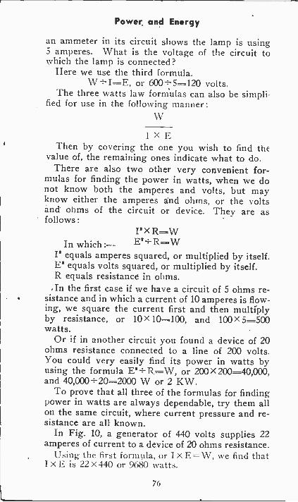
Power and Energy
an ammeter in its circuit shows the lamp is using5 amperes. What is the voltage of the circuit towhich the lamp is connected?
Here we use the third formula.or 600-i-5=120 volts.
The three watts law forniulas can also be simpli-fied for use in the following manner:
1 X EThen by covering the one you wish to find the
value of, the remaining ones indicate what to do.There are also two other very convenient for-
mulas for finding the power in watts, when we donot know both the amperes and volts, but mayknow either the amperes and ohms, or the voltsand ohms of the circuit or device. They are asfollows :
I' xIn which:- Ei÷R="'W
I' equals amperes squared, or multiplied by itself.E' equals volts squared, or multiplied by itself.R equals resistance in ohms.In the first case if we have a circuit of 5 ohms re-
sistance and in which a current of 10 amperes is flow-ing, we square the current first and then multiplyby resistance, or 10X 10=100, and 100X 5=500watts.
Or if in another circuit you found a device of 20ohms resistance connected to a line of 200 volts.You could very easily find its power in watts byusing the formula E3-s-R-W, or 200>< 200=40,000,and 40,000 ÷ 20=2000 W or 2 KW.
To prove that all three of the formulas for findingpower in watts are always dependable, try them allon the same circuit, where current pressure and re-sistance are all known.
In Fig. 10, a generator of 440 volts supplies 22amperes of current to a device of 20 ohms resistance.
Ling the fir -,t formula, or I x E= \V, we find thatI X E is 22 X 440 or 9680 watts.
76
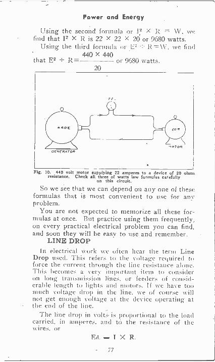
Power and Energy
Using the second formula or 12 X W. wefind that 12 X R is 22 X 22 X 20 or 9680 watts.
Using the third formula or E2 R W. we find440 X 440
that E2 R- or 9680 watts.20
GENERATOR
Fig. 10. 440 volt motor supplying 22 amperes to a device of 20 ohmsresistance. Check all three of watts law formulas carefully
on this circuit.
So we see that we can depend on any one of theseformulas that is most convenient to use for anyproblem.
You are not expected to memorize all these for-mulas at once. But practice using them frequently,on every practical electrical problem you can find,and soon they will he easy to use and remember.
LINE DROPiii electrical work we often hear the term Line
Drop used. This refers to the voltage required toforce the current through theline resistance alone.This becomes a very important item to consideron long transmission lines, or feeders of consid-erable length to lights and motors. If we have toomuch voltage drop in the line, we of course \ v i 11
not get enough voltage at the device operating atthe end of the line.
The line drop in volts is proportional to the loadcarried. in amperes, and to the resistance of thewires, or
Ed..... I X R.
77
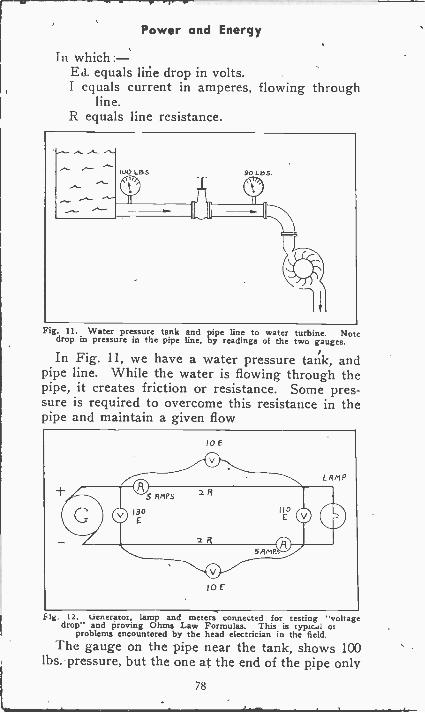
Power and Energy
In whichEd. equals line drop in volts.I equals current in amperes, flowing through
line.R equals line resistance.
Fig. 11. Water pressure tank and pipe line to water turbine. Notedrop in pressure in the pipe line, by readings of the two gauges.
In Fig. 11, we have a water pressure tank, andpipe line. While the water is flowing through thepipe, it creates friction or resistance. Some pres-sure is required to overcome this resistance in thepipe and maintain a given flow
I 0 E
I o r
Fig. 12. uenerator, lamp and meters connected for testing "voltagedrop" and proving Ohms Law Formulas. This is typical 01
problems encountered by the head electrician in the field.The gauge on the pipe near the tank, shows 100
lbs. pressure, but the one at the end of the pipe only
78
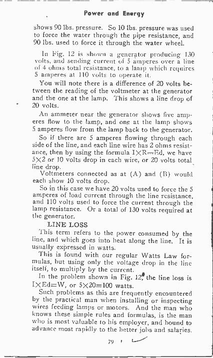
Power and Energy
shows 90 lbs. pressure. So 10 lbs. pressure was usedto force the water through the pipe resistance, and90 lbs. used to force it through the water wheel.
In Fig. 12 is shown a genertor producing 130volts, and sending current of 5 amperes over a lineof 4 ohms total resistance, to a lamp which requires5 amperes at 110 volts to operate it.
You will note there is a difference Of 20 volts be-tween the reading of the voltmeter at the generatorand the one at the lamp. This shows a line drop of20 volts.
An ammeter near the generator shows five amp-eres flow to the lamp, and one at the lamp shows5 amperes flow from the lamp back to the generator.
So if there are 5 amperes flowing through eachside of the line, and each line wire has 2 ohms resist-ance, then by using the formula IXR-Ed, we have5X2 or 10 volts drop in each wire, or 20 volts totalline drop.
Voltmeters connected as at (A) and (B) wouldeach show 10 volts drop.
So in this case we have 20 volts used to force the 5amperes of load current through the line resistance,and 110 volts used to force the current through thelamp resistance. Or a total of 130 volts required atthe generator.
LINE LOSSThis term refers to the power consumed by the
line, and which goes into heat along the line. It isusually expressed in watts.
This is found with our regular Watts Law for-mulas, but using only the voltage drop in the lineitself, to multiply by the current.
In the problem shown in Fig. 12, line loss isI X Ed=W, or 5X20=100 watts.
Such problems as this are frequently encounteredby the practical man when installing or inspectingwires feeding lamps or motors. And the man whoknows these simple rules and formulas, is the manwho is most valuable to his employer, and bound toadvance most rapidly to the better jobs and salaries.
79 I
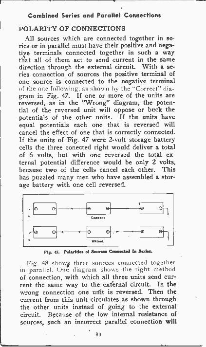
Combined Series and Parallel Connections
POLARITY OF CONNECTIONSAll sources which are connected together in se-
ries or in parallel must have their positive and nega-tive terminals connected together in such a waythat all of them act to send current in the samedirection through the external circuit. With a se-ries connection of sources the positive terminal ofone source is connected to the negative terminal01 the one folltming, as shown by the "Correct.' dia-gram in Fig. 47. If one or more of the units arereversed, as in the "Wrong" diagram, the poten-tial of the reversed unit will oppose or buck thepotentials of the other units. If the units haveequal potentials each one that is reversed willcancel the effect of one that is correctly connected.If the units of Fig. 47 were 2 -volt storage batterycells the three conected right would deliver a totalof 6 volts, but with one reversed the total ex-ternal potential difference would be only 2 volts,because two of the cells cancel each other. Thishas puzzled many men who have assembled a stor-age battery with one cell reversed.
Fig. 47. Polarities of Sources Connected In Series.
Fig. 48 show three sources connected togetherin parallel. hte diagram shows the right methodof connection, with which all three units send cur-rent the same way to the external circuit. In thewrong connection one unit is reversed. Then thecurrent from this unit circulates as shown throughthe other units instead of going to the externalcircuit. Because of the low internal resistance ofsources, such an incorrect parallel connection will
80
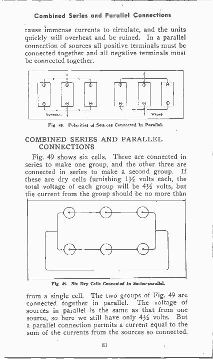
Combined Series and Parallel Connections
cause immense currents to circulate, and the unitsquickly will overheat and be ruined. In a parallelconnection of sources all positive terminals must beconnected together and all negative terminals mustbe connected together.
Fig 4$. Polarities of Sources Connected In FeralleL
COMBINED SERIES AND PARALLELCONNECTIONS
Fig. 49 shows six cells. Three are connected inseries to make one group, and the other three areconnected in series to make a second group. Ifthese are dry cells furnishing I% volts each, thetotal voltage of each group will be 4% volts, butthe current from the group should be no more than
O 0 0
0 0 O
Fig 49. Sia Dry Cella Connected In Series-paralleL
from a single cell. The two groups of Fig. 49 areconnected together in parallel. The voltage ofsources in parallel is the same as that from onesource, so here we still have only 4% volts. Buta parallel connection permits a current equal to thesum of the currents from the sources so connected.
81
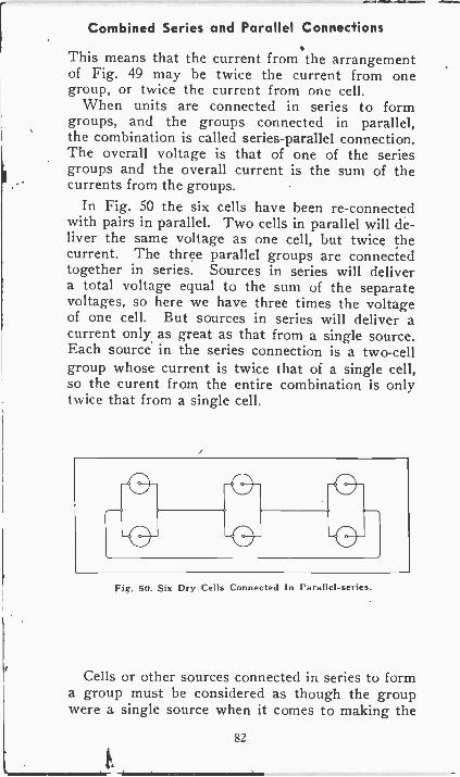
Combined Series and Parallel Connections
This means that the current from the arrangementof Fig. 49 may be twice the current from onegroup, or twice the current from one cell.
When units are connected in series to formgroups, and the groups connected in parallel,the combination is called series -parallel connection.The overall voltage is that of one of the seriesgroups and the overall current is the sum of thecurrents from the groups.
In Fig. 50 the six cells have been re -connectedwith pairs in parallel. Two cells in parallel will de-liver the same voltage as one cell, but twice thecurrent. The three parallel groups are connectedtogether in series. Sources in series will delivera total voltage equal to the sum of the separatevoltages, so here we have three times the voltageof one cell. But sources in series will deliver acurrent only as great as that from a single source.Each source in the series connection is a two -cellgroup whose current is twice that of a single cell,so the curent from the entire combination is onlytwice that from a single cell.
Fig. 50. Six Dry Cells Connected In Parallel -series.
Cells or other sources connected in series to forma group must be considered as though the groupwere a single source when it comes to making the
82
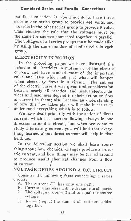
Combined Series and Parallel Connections
parallel connection. It Nv ould not do to have threecells in one series group to provide 4Y2 volts, andsix cells in the other series group to provide 9 volts.This violates the rule that the voltages must bethe same for sources connected together in parallel.The voltages of all series groups must be made alikeby using the same number of similar cells in eachgroup.
ELECTRICITY IN MOTIONIn the preceding pages we have discussed the
behavior of electricity in motion or of the electriccurrent, and have studied most of the importantrules and laws which tell just what will happenwhen electricity flows in a circuit. The subjectof the electric current was given first considerationbecause nearly all practical and useful electric de-vices and machines depend for their action on flowof current in them ; also because an understandingof how this flow takes place will make it easier tounderstand everything which is to follow.
We have dealt primarily with the action of directcurrent, which is a current flowing always in onedirection around a circuit, but when we come tostudy alternating current you will find that every-thing learned about direct current will help in thatfield, too.
In the following section we shall learn some-thing about how chemical changes produce an elec-tric current, and how things may be turned aroundto produce useful ,Chemicalchanges from a flowof current.VOLTAGE DROPS AROUND A D.C. CIRCUIT
Consider the following facts concerning a seriescircuit :
A. The current (I) has only one path.B. Current in amperes will he the same in all parts.C. The voltage drops will add to equal the source
voltage.I). RT will equal the sum of all resistors added
together.
83
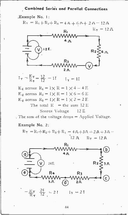
Combined Series and Parallel Connections
Example No. 1:RT -= 4 11- + 6 A+ 2 = 12 IL
RT - 12 IL
6_11.
211
IT =RT-12 =1I IT -- 11
Ed across R1= IX R= 1 X 4 = 4 EEd across R2=IXR=1X6= 6 EEd across R3=IXR=1X2= 2 E
The total E = the sum 12 ESource Voltage 12 E
The sum of the voltage (Hops = Applied Voltage.
Example No. 2:
RT =R1d-R2d-R3-ER4 = 411+311+211+311=12 11 RT= 1211
R
=ET 24RT 12 2 I
I7 2I
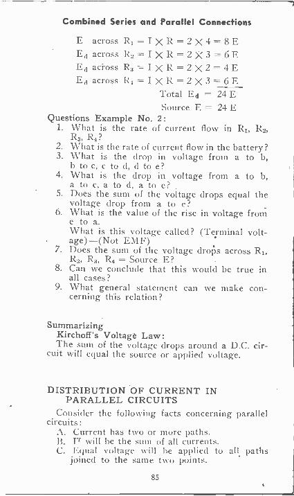
Combined Series and Parallel Connections
E across Ri IXRR-2X4=8EEd across R2=IXR=2X3= 6 EEd across R3=IXR=2X2= 4 EEd across R4=IXR= 2 X 3 = 6 E
Total Ed = 24 ESource E = 24 E
Questions Example No. 2:1. What is the rate of current flow in R1, R2,
R3, 124 ?2. What is the rate of current flow in the battery?3. What is the drop in voltage from a to b,
b to c, c to d, d to e?4. What is the drop in voltage from a to b,
a to c, a to d, a to e?5. Does the sum of the voltage drops equal the
voltage drop from a to e?6. What is the value of the rise in voltage from
e to a.What is this voltage called? (Terminal volt-age)-(Not EMF)
7. Does the sum of the voltage drops across R1,R2, R3, R4 = Source E?
8. Can we conclude that this would be true inall cases?
9. What general statement can we make con-cerning this relation?
SummarizingKirchoff's Voltage Law:The sum of the voltage drops around a D.C. cir-
cuit will equal the source or applied voltage.
DISTRIBUTION OF CURRENT INPARALLEL CIRCUITS
Consider the following facts concerning parallelcircuits:
A. Current has two or more paths.. B. IT will be the sum of all currents.
C. Equal voltage will be applied to all pathsjoined to the same two points.
85
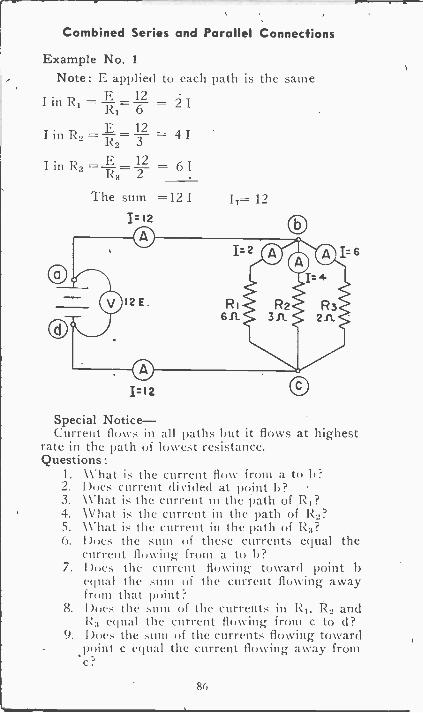
Combined Series and Parallel Connections
Example No. 1Note: E applied to each path is the same
in RI = R1= =
in R2 = Tt= 132 4 I
IinR3= R3= 2 = 6I12
The sum =12 11.1. 12
IT= 12
Special Notice-Current flows in all paths but it flows at highest
rate in the path of lowest resistance.Questions :
1. What is the current flow from a to 1)?2. Does current divided at point I)?3. What is the current in the path of R1?4. What is the current in the path of5. What is the current in the path of R3?6. Does the sum of these currents equal the
current flowing- from a to I)?7. Does the current flowing toward point h
equal the sum of the current flowing awayfrom that point?
8. Does the sum of the currents in RI, R2 andI equal the current flowing from c to d?
9. Does the sum of the currents flowing towardpoint c equal the current flowing away fromc?
86
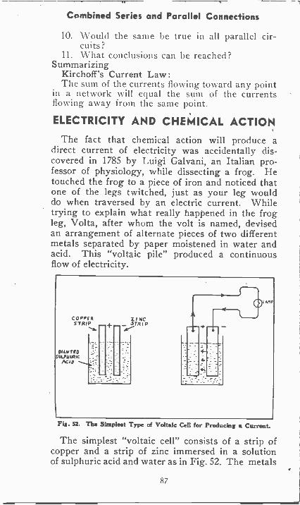
Combined Series and Parallel Connections
10. Would the same be true in all parallel cir-cuits?
11. What conclusions can be reached?Summarizing
Kirchoff's Current Law:The sum of the currents flowing toward any point
in a network will equal the sum of the currentsflowing away from the same point.
ELECTRICITY AND CHEMICAL ACTION
The fact that chemical action will produce adirect current of electricity was accidentally dis-covered in 1785 by Luigi Galvani, an Italian pro-fessor of physiology, while dissecting a frog. Hetouched the frog to a piece of iron and noticed thatone of the legs twitched, just as your leg woulddo when traversed by an electric current. Whiletrying to explain what really happened in the frogleg, Volta, after whom the volt is named, devisedan arrangement of alternate pieces of two differentmetals separated by paper moistened in water andacid. This "voltaic pile" produced a continuousflow of electricity.
COPPISTRIP
ti
DI LUTE '0suuNurtic
Kip
Z. RC-STRIP
0 L NIP
Fia. 52. The Simplest Type of Voltaic Cell for Producing a Current.
The simplest "voltaic cell" consists of a strip ofcopper and a strip of zinc immersed in a solutionof sulphuric acid and water as in Fig. 52. The metals
87
Cells
are called elements or plates, and the liquid iL
called the electrolyte. An electrolyte is a mixturewith water of any substance which permit theliquid to act as a conductor for electricity. Thesubstances used are salts, acids or alkalies.
PRIMARY AND SECONDARY CELLSIf the elements of the cell in Fig. 52 are con-
nected to an external circuit, current will flowthrough this circuit from the copper element to thezinc element. The copper has become positivewith reference to the zinc, which is negative. Atthe same time the zinc will commence dissolvinginto the acid electrolyte and be destroyed. Hydro-gen gas will separate from the acid and collect asbubbles on the copper. The gas is an insulator,and after a short time will so cover the copper asto prevent further flow of current.
All practical cells which produce current by de-struction of a metal have zinc Or some compoundof zinc for one of their elements, and the zinc ele-ment always is negative. In all these cells the zincis gradually dissolved or eaten away, but nothinghappens to the other element, which is positive. Inall cells there is a pronounced tendency for gas tocollect on the positive element and to retard orprevent flow of current. This action of the gasis called polarization of the cell. Most of the dif-ferences between various types of cells are due tothe different methods of removing the gas orof depolarizing the cell so that it may continue tofurnish current. When nearly all of the zinc hasbeen eaten away, or when there is practically nomore hydrogen to separate from the electrolyte,the useful life of the cell is ended.
An electric cell which produces an emf and a flowof current while its elements and electrolyte un-dergo changes which render them no longer usefulis called a primary cell.
When discussing Fig. 16 we talked about a cellin which the chemical changes may be reversed by
88
Cells
sending through the cell a current in a directionthe opposite of that which the cell furnishes to anexternal circuit. There the elements or plates andthe electrolyte are restored to their original con-dition and the cell again is ready to provide anemf and current flow. Such a reversible cell iscalled a secondary cell to distinguish it from a pri-mary cell. Secondary cells usually are calledstorage cells, and two or more connected togetherare a storage battery. Fig. 53 illustrates a numberof large storage batteries used for furnishing cur-rent in telephone work.
CELL CURRENT AND VOLTAGEThe emf and potential difference produced by any
voltaic cell, primary or secondary, depends entirelyon the materials in the plates and in the electro-lyte and not at all on the size or construction. Acell the size of your little finger would furnishjust the same potential difference as any cell in thebatteries of Fig. 53, provided both contained thesame kinds of elements and electrolyte.
The current that may be taken from a voltaiccell as a source depends on the the emf of the cell,on the internal resistance of the cell and the re-sistance of the connected circuit, and on the degreeto which polarization increases the internal resist-ance and thus cuts down the current. Current flowfrom a cell follows Ohm's law, I = E/R, just asdoes current in every other circuit containing anemf and resistance.
The total quantity of current that may be takenfrom any voltaic cell before the cell becomes dis-charged depends on the quantities of active chemi-cal materials in the plates and the electrolyte. Sincemore material means a bigger cell or battery, it fol-lows that the bigger the cell or battery the moreelectricity it will deliver. The quantity of electricitydelivered might be measured in coulombs, butnearly always is measured in ampere -hours. Thequantity actually is measured as the number of
89
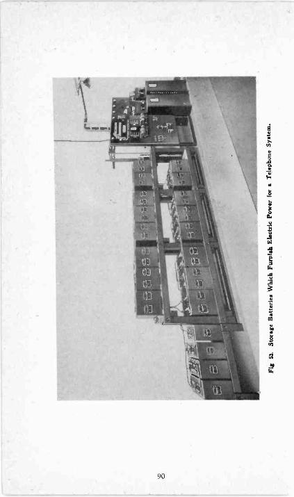
Fig
53.
Stor
age
Bat
teri
es W
hich
Fur
nish
Ele
ctri
c Po
wer
for
Tel
epho
ne S
yste
m.
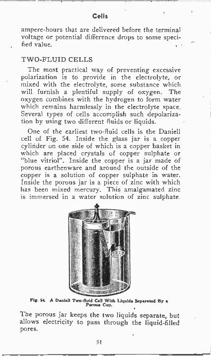
Cells
ampere -hours that are delivered before the terminalvoltage or potential difference drops to some speci-fied value.
TWO -FLUID CELLSThe most practical way of preventing excessive
polarization is to provide in the electrolyte, ormixed with the electrolyte, some substance whichwill furnish a plentiful supply of oxygen. Theoxygen combines with the hydrogen to form waterwhich remains harmlessly in the electrolyte space.Several types of cells accomplish such depolariza-tion by using two different fluids or liquids.
One of the earliest two -fluid cells is the Daniellcell of Fig. 54. Inside the glass jar is a coppercylinder on one side of which is a copper basket inwhich are placed crystals of copper sulphate or"blue vitriol". Inside the copper is a jar made ofporous earthenware and around the outside of the
a solution of copper sulphate in water.Inside the porous jar is a piece of zinc with whichhas been mixed mercury. This amalgamated zincis immersed in a water solution of zinc sulphate.
c 1.4caaniall>0
Fig. St A Daniell Two -fluid Cell With Liquids Separated By Porous Cup.
The porous jar keeps the two liquids separate, butallows electricity to pass through the liquid -filledpores.
91
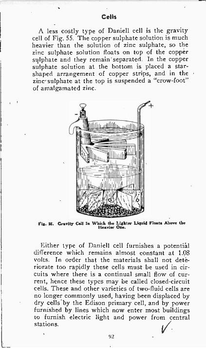
Cells
A less costly type of Daniell cell is the gravitycell of Fig. 55. The copper sulphate solution is muchheavier than the solution of zinc sulphate, so thezinc sulphate solution floats on top of the coppersulphate and they remain separated. In the coppersulphate solution at the bottom is placed a star -shaped arrangement of copper strips, and in thezinc sulphate at the top is suspended a "crow -foot"of amalgamated zinc.
Fis. SS. Gravity Cell In Which the Lighter Liquid Floats Above theHeavier One.
Either type of Daniell cell furnishes a potentialdifference which remains almost constant at 1.08volts. In order that the materials shall not dete-riorate too rapidly these cells must be used in cir-cuits where there is a continual small flow of cur-rent, hence these types may be called closed-circuitcells. These and other varieties of two -fluid cells areno longer commonly used, having been displaced bydry cells -by the Edison primary cell, and by powerfurnished by lines which now enter most buildingsto furnish electric light and power from centralstations.
92
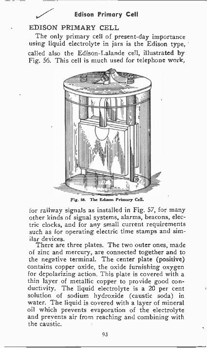
Edison Primary Cell
EDISON PRIMARY CELLThe only primary cell of present-day importance
using liquid electrolyte in jars is the Edison type,called also the Edison-Lalande cell, illustrated byFig. 56. This cell is much used for telephone work,
I
Fig. H. The Edison Primary Cell.
for railway signals as installed in Fig. 57, for manyother kinds of signal systems, alarms, beacons, elec-tric clocks, and for any small current requirementssuch as for operating electric time stamps and sim-ilar devices.
There are three plates. The two outer ones, madeof zinc and mercury, are connected together and tothe negative terminal. The center plate (positive)contains copper oxide, the oxide furnishing oxygenfor depolarizing action. This plate is covered with athin layer of metallic copper to provide good con-ductivity. The liquid electrolyte is a 20 per centsolution of sodium hydroxide (caustic soda) inwater. The liquid is covered with a layer of mineraloil which prevents evaporation of the electrolyteand prevents air from reaching and combining withthe caustic.
93
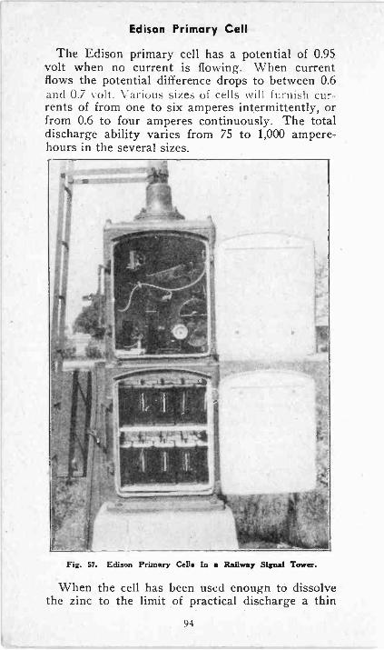
Edison Primary Cell
The Edison primary cell has a potential of 0.95volt when no current is flowing. When currentflows the potential difference drops to between 0.6and 0.7 volt. Various sizes of cells will furnish cur-rents of from one to six amperes intermittently, orfrom 0.6 to four amperes continuously. The totaldischarge ability varies from 75 to 1,000 ampere -
hours in the several sizes.
Fig. 57. Edison Primary Cells In a Railway Signal Tower.
When the cell has been used enough to dissolvethe zinc to the limit of practical discharge a thin
94
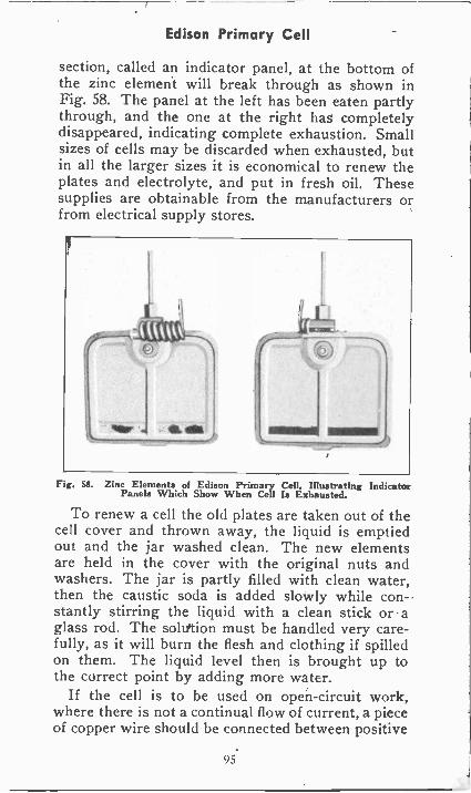
Edison Primary Cell
section, called an indicator panel, at the bottom ofthe zinc element will break through as shown inFig. 58. The panel at the left has been eaten partlythrough, and the one at the right has completelydisappeared, indicating complete exhaustion. Smallsizes of cells may be discarded when exhausted, butin all the larger sizes it is economical to renew theplates and electrolyte, and put in fresh oil. Thesesupplies are obtainable from the manufacturers orfrom electrical supply stores.
Fig. SS. Zinc Elements of Edison Primary Cell, Illustrating IndicatorPanels Which Show When Cell Is Exhausted.
To renew a cell the old plates are taken out of thecell cover and thrown away, the liquid is emptiedout and the jar washed clean. The new elementsare held in the cover with the original nuts andwashers. The jar is partly filled with clean water,then the caustic soda is added slowly while con-stantly stirring the liquid with a clean stick or aglass rod. The soluttion must be handled very care-fully, as it will burn the flesh and clothing if spilledon them. The liquid level then is brought up tothe correct point by adding more water.
If the cell is to be used on open -circuit work,where there is not a continual flow of current, a pieceof copper wire should be connected between positive
95.
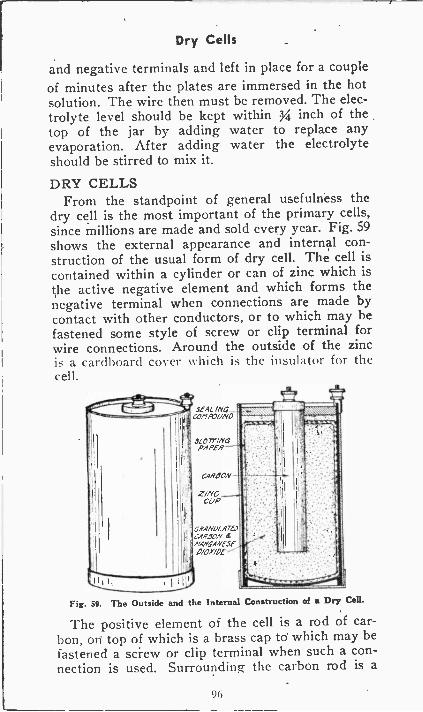
Dry Cells
and negative terminals and left in place for a coupleof minutes after the plates are immersed in the hotsolution. The wire then must be removed. The elec-trolyte level should be kept within 3/4 inch of thetop of the jar by adding water to replace anyevaporation. After adding water the electrolyteshould be stirred to mix it.
DRY CELLSFrom the standpoint of general usefulness the
dry cell is the most important of the primary cells,since millions are made and sold every year. Fig. 59
shows the external appearance and internal con-struction of the usual form of dry cell. The cell iscontained within a cylinder or can of zinc which isthe active negative element and which forms thenegative terminal when connections are made bycontact with other conductors, or to which may befastened some style of screw or clip terminal forwire connections. Around the outside of the zincis a cardboard cover which is the insulator for thecell.
SEAL MG_cOr7POUNO
077-ilYPAPER
CARBON
2/NCCUP
GRANuLATL,CARBON etMANGANESE0/0X/Of
Fig. 59. The Outside and the Internal Construction of a Dry Cell.
The positive element of the cell is a rod of car-bon, on top of which is a brass cap to which may befastened a screw or clip terminal when such a con-nection is used. Surrounding the carbon rod is a
9(
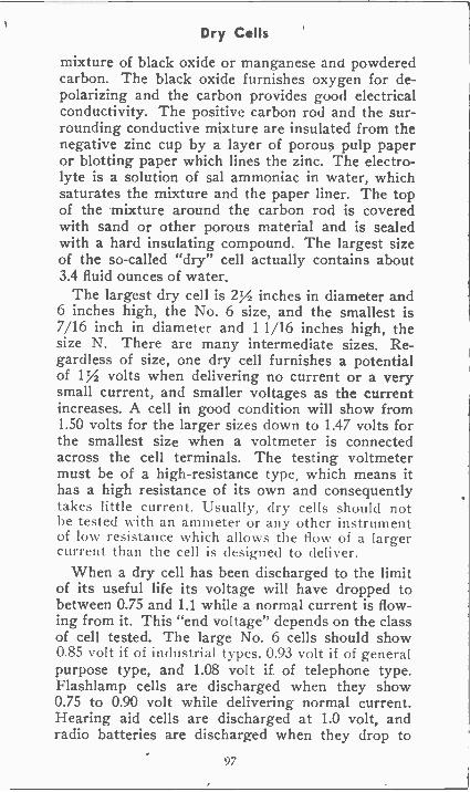
Dry Cells
mixture of black oxide or manganese and powderedcarbon. The black oxide furnishes oxygen for de-polarizing and the carbon provides good electricalconductivity. The positive carbon rod and the sur-rounding conductive mixture are insulated from thenegative zinc cup by a layer of porous pulp paperor blotting paper which lines the zinc. The electro-lyte is a solution of sal ammoniac in water, whichsaturates the mixture and the paper liner. The topof the mixture around the carbon rod is coveredwith sand or other porous material and is sealedwith a hard insulating compound. The largest sizeof the so-called "dry" cell actually contains about3.4 fluid ounces of water.
The largest dry cell is 2% inches in diameter and6 inches high, the No. 6 size, and the smallest is7/16 inch in diameter and 1 1/16 inches high, thesize N. There are many intermediate sizes. Re-gardless of size, one dry cell furnishes a potentialof 1% volts when delivering no current or a verysmall current, and smaller voltages as the currentincreases. A cell in good condition will show from1.50 volts for the larger sizes down to 1.47 volts forthe smallest size when a voltmeter is connectedacross the cell terminals. The testing voltmetermust be of a high -resistance type, which means ithas a high resistance of its own and consequentlytakes little current. Usually, dry cells should nothe tested with an ammeter or any other instrumentof low resistance which allows the flow of a largercurrent than the cell is designed to deliver.
When a dry cell has been discharged to the limitof its useful life its voltage will have dropped tobetween 0.75 and 1.1 while a normal current is flow-ing from it. This "end voltage" depends on the classof cell tested. The large No. 6 cells should show0.85 volt if of industrial types. 0.93 volt if of generalpurpose type, and 1.08 volt if of telephone type.Flashlamp cells are discharged when they show0.75 to 0.90 volt while delivering normal current.Hearing aid cells are discharged at 1.0 volt, andradio batteries are discharged when they drop to
97
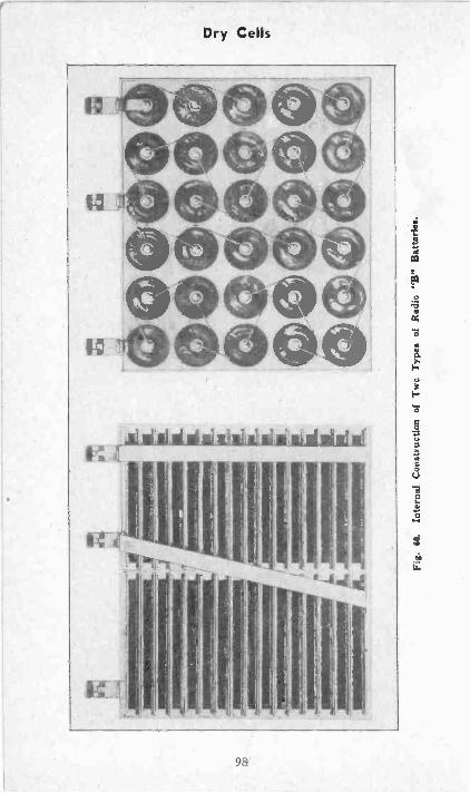
Fig.
60.
Inte
rnal
Con
stru
ctio
n of
Tw
o T
ypes
of
Rad
io "
B"
Bat
teri
es.
Dry Cells
between 1.0 and 1.1 volts per cell.Radio batteries consist of a number of dry cells
assembled in a case and connected togehter in seriesto furnish various total voltages. Fig. 60 shows atthe left a battery assembled with. a special form offlat cells which save space and at the right an other-wise similar battery made up from cylindrical cells.The series connection shows up clearly in the right-hand picture. Here the left-hand terminal is thenegative terminal. From here to the middle terminalthere are 15 cells in series, providing 22Y2 volts at1Y2 volts per cell. From the middle to the right-hand terminal there are 15 more cells, providing anadditional 22Y2 volts. Consequently, between theleft-hand terminal and middle terminal, or from themiddle to the right-hand terminal we may obtaair221/2 volts, and from the left-hand to the right-handterminals may obtain 45 volts. Radio batteries instandard types may contain as many as 60 cells, toprovide 90 volts. All the internal series connectionsare soldered or welded.
Dry cells deteriorate even if not used. A goodcell may be kept idle or stored for about a yearbefore deterioration is at all serious. Of a numberof cells stored, five or six per cent will show anoticeable drop in voltage at the end of six months.Deterioration will be much worse if the cells arestored where it is damp, or where the temperatureis very high. When the voltage of a dry cell hasdropped, the internal resistance has increased to ahigh value. Therefore, one low -voltage cell used ina series or parallel group with other good cells willgreatly reduce the voltage or current from thewhole group. A badly discharged dry cell often willshow bulges or wet spots on the cardboard coverwhere the zinc has been eaten nearly or entirelythrough.
Being of the primary type, dry cells cannot berecharged ; however, the life of such cells may beconsiderably extended by periodically passingthrough them a low value of current. Commercialcharging devices are now available to simplify such
99
Batteries-Air Cell
recovery, and the procedure consists merely of con-necting the dry cell to the proper voltage and al-lowing current of a relatively low value to flowthrough it for about 24 hours. Proper restorationprocedure may increase the life of the ordinary drycell many times.AIR -CELL BATTERY
The air -cell battery or air -depolarized battery isa type designed for radio use. The negative elementis zinc. The positive element is a rod of porouscarbon which extends through the cell cover to theoutside of the battery so that oxygen from the out-side air may enter through the pores of the carborto effect depolarization. The electrolyte is a solu-tion of caustic soda in water.
Each air cell furnishes a potential difference of1.25 volts while delivering its normal current. Thecell potential will drop gradually to about 1.15volts at the end of its useful life. The air cell cannotbe recharged nor can its elements be renewed. Theonly care required during the life of such a batteryis to periodically add clean water through a filleropening to keep the electrolyte level at the correctpoint.
STORAGE CELLS AND STORAGEBATTERIES
Storage battery cells may be of the type usingplates of lead and lead peroxide with an electrolyteof diluted sulphuric acid. This is called the lead -acid type. Another type uses plate materials ofiron and nickel with a caustic electrolyte. This isthe Edison storage battery or the nickel -iron -alka-line storage battery. Both of these types of storagebatteries will be examined in detail during a latersection of our work.
ELECTROLYTE CELLSAt the left-hand side of Fig. 61 we have a plate
of zinc and another of carbon immersed in an elec-trolyte and connected through an external resistor.
100
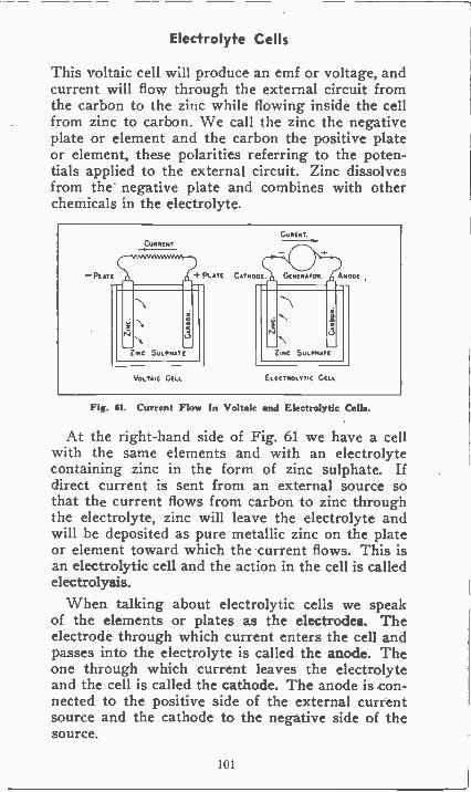
Electrolyte Cells
This voltaic cell will produce an emf or voltage, andcurrent will flow through the external circuit fromthe carbon to the zinc while flowing inside the cellfrom zinc to carbon. We call the zinc the negativeplate or element and the carbon the positive plateor element, these polarities referring to the poten-tials applied to the external circuit. Zinc dissolvesfrom the negative plate and combines with otherchemicals in the electrolyte.
Fig. $1. Current Flow In Voltaic and Electrolytic Cells.
At the right-hand side of Fig. 61 we have a cellwith the same elements and with an electrolytecontaining zinc in the form of zinc sulphate. Ifdirect current is sent from an external source sothat the current flows from carbon to zinc throughthe electrolyte, zinc will leave the electrolyte andwill be deposited as pure metallic zinc on the plateor element toward which the current flows. This isan electrolytic cell and the action in the cell is calledelectrolysis.
When talking about electrolytic cells we speakof the elements or plates as the electrodes. Theelectrode through which current enters the cell andpasses into the electrolyte is called the anode. Theone through which current leaves the electrolyteand the cell is called the cathode. The anode is con-nected to the positive side of the external currentsource and the cathode to the negative side of thesource.
101
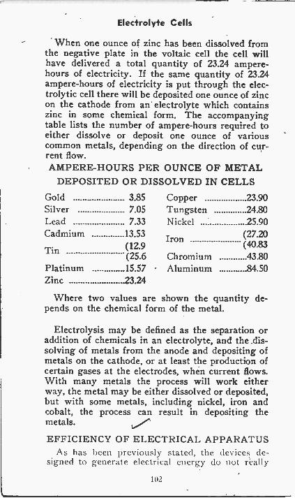
Electrolyte Cells
When one ounce of zinc has been dissolved fromthe negative plate in the voltaic cell the cell willhave delivered a total quantity of 23.24 ampere -hours of electricity. If the same quantity of 23.24ampere -hours of electricity is put through the elec-trolytic cell there will be deposited one ounce of zincon the cathode from an electrolyte which containszinc in some chemical form. The accompanyingtable lists the number of ampere -hours required toeither dissolve or deposit one ounce of variouscommon metals, depending on the direction of cur-rent flow.AMPERE -HOURS PER OUNCE OF METAL
DEPOSITED OR DISSOLVED IN CELLSGold 3.85 Copper 23.90Silver 7.05 Tungsten 24.80Lead 7.33 Nickel 25.90Cadmium 13.53 Iron (27.20
Tin (12.9(25.6 Chromium
(40.8343.80
Platinum 15.57 Aluminum 84.50Zinc 23.24
Where two values are shown the quantity de-pends on the chemical form of the metal.
Electrolysis may be defined as the separation oraddition of chemicals in an electrolyte, and the .dis-solving of metals from the anode and depositing ofmetals on the cathode, or at least the production ofcertain gases at the electrodes, when current flows.With many metals the process will work eitherway, the metal may be either dissolved or deposited,but with some metals, including nickel, iron andcobalt, the process can result in depositing themetals.
EFFICIENCY OF ELECTRICAL APPARATUSAs has been previously stated, the devices de-
signed to generate electrical energy do not really
102
Efficiency of Electrical Apparatus
generate at all ; instead, they convert some otherform of energy into electrical energy ; for example,the regular D.C. generator merely converts mechan-ical energy provided by the driving' unit into elec-trical energy, while the dry cell or the storage batteryconverts chemical energy into electrical energy.
The process of converting energy from one formto another always involves a loss of some of theuseful energy ; in other words, it is not possible toobtain from any conversion device as much usefulenergy as was put into it. In the case of the gen-erator, some of the mechanical energy required todrive it is lost in overcoming bearing friction, wind-age, and brush friction ; moreover, some of the elec-trical energy produced is wasted inside the gen-erator due to the heat generated by the armaturecurrent flowing through the resistance of the arma-ture winding. .
As it is impassible to get out of any conversiondevice as much useful energy as was put into it,it becomes of interest to consider just how effectivea given device will be in converting some otherform of energy into electrical energy ; this questionbrings us to the problem of efficiency. If we putinto the input end of a given conversion device agiven amount of energy, and if we were able totake from the output end the same amount of en-ergy, then we would have a conversion device thathad an efficiency of 100 per cent. If we were ableto obtain from the output end only one half of theenergy put in, then the efficiency of the devicewould be only 50 per cent. Although large gen-erators usually have an efficiency considerably above90 per cent, there are many types of electrical ap-paratus that have much lower efficiencies; for ex-ample, many fractional horsepower types of motorssuch as those used on fans, sewing machines, wash-ers, drills, and similar applications convert less than50 per cent of the electrical energy supplied to theminto useful mechanical energy, the rest being con-verted mostly into useless heat inside the machine.Such machines may then be said to be less than 50per cent efficient.
Consideration of the above material shows thatthe efficiency of a conversion device is the relation -
103
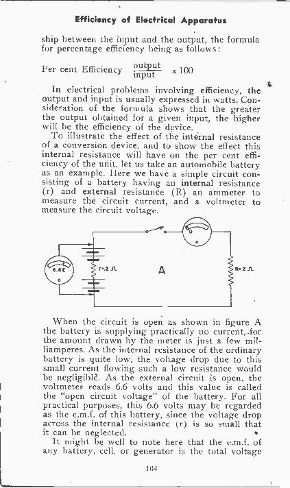
Efficiency of Electrical Apparatus
ship between the input and the output, the formulafor percentage efficiency being as follows:
Per cent Efficiency 9utputx 100input
In electrical problems involving efficiency, theoutput and input is usually expressed in watts. Con-sideration of the formula shows that the greaterthe output obtained for a given input, the higherwill be the efficiency of the device.
To illustrate the effect of the internal resistanceof a conversion device, and to show the effect thisinternal resistance will have on the per cent effi-ciency of the unit, let us take an automobile batteryas an example. Here we have a simple circuit con-sisting of a battery having an internal resistance(r) and external resistance (R) an ammeter tomeasure the circuit current, and a voltmeter tomeasure the circuit voltage.
r:.2 A R s 2 ft
When the circuit is open as shown in figure Athe battery is supplying practically no current, .forthe amount drawn by the meter is just a few mil-liamperes. As the internal resistance of the ordinarybattery is quite low, the voltage drop due to thissmall current flowing such a low resistance wouldbe negligible. As the external circuit is open, thevoltmeter reads 6.6 volts and this value is calledthe "open circuit voltage" of the battery. For allpractical purposes, this 6.6 volts may be regardedas the e.m.f. of this battery, since the voltage dropacross the internal resistance (r) is so small thatit can be neglected.
It might be well to note here that the e.m.f. ofany battery, cell, or generator is the total voltage
104
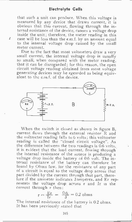
Electrolyte Cells
that such a unit can produce. When this voltage ismeasured by any device that draws current, it isobvious that this current, flowing through the in-ternal resistance of the device, causes a voltage dropinside the unit; therefore, the meter reading in thiscase will be less than the e.m.f. by an amount equalto the internal voltage drop caused by the smallmeter current.
Due to the fact that most voltmeters draw a verysmall current, the internal voltage drop is usuallyso small, when compared with the meter reading,that it can be disregarded; for this reason, the opencircuit voltage reading obtained from most voltagegenerating devices may be rgearded as being equiv-alent to the e.m.f. of the device.
When the switch is closed as shown in figure B,current flows through the external resistor R andthe voltmeter reading falls to 6 volts; this voltmeterreading is called the "closed circuit voltage". Asthe difference between the two readings is 0.6 volts,it is evident that the load current, flowing throughthe internal resistance of the source is producing avoltage drop inside the battery of 0.6 volt. The in-ternal resistance of the battery can therefore befound by Ohms law, for the resistance -of any partof a circuit is equal to the voltage drop across thatpart divided by the current through that part, there-fore if the ammeter indicates 3 amperes, and Er rep-resents the voltage drop across r and Ir is thecurrent through r then :
r= Jr - 3Er 0.6 = 0.2 ohms
The internal resistance of the battery is 0.2 ohms.It has been previously stated that
105
Electrolyte Cells
Per cent Eff. = inputoutput
x 100
But, as we have no direct means of measuringthe input to a battery, we must use a different for-mula. As the input of any device is equal to theoutput plus the losses in the device, we may sub-stitute "output + losses" for input and this gives
outputQfo Eff. - x 100output + losses
Expressing all values in watts we haveoutput = 12R = 3x3x2 = 18 wattslosses = 12r = 3x3x0.2 = 1.8 watts
per cent Eff. - outputoutput + losses
18 x 100- 18 + 1.8
18 10019.8
x 100
= 91% approx.
Since only 91% of the total. energy appears in theexternal circuit 9% is lost, mostly in uselessly heat-ing the battery.
If the internal resistance were increased, the effi-ciency of the battery would be still further reduceduntil, when the internal resistance became equal tothe external resistance, the efficiency of the batterywould have fallen to 50 per cent. Thus it is evidentthat for high efficiency, the internal resistanceshould be kept as low as possible. ,
ELECTROPLATINGOne of the most useful applications of electrolysis
is in the plating of certain metals over other basemetals to provide decorative effects, to provide pro-tection against rust and corrosion, to provide awear -resisting surface, or even for the building upand replacement of worn surfaces. Most electro-plating is done with chromium, gold, silver, nickel,brass, copper, chromium and zinc although some
106
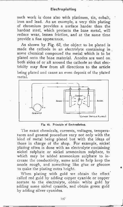
Electroplating
such work is done also with platinum, tin, cobalt,iron and lead. As an example, a very thin platingof chromium provides a surface harder than thehardest steel, which protects the base metal, willreduce wear, lessen friction, and at the same timeprovide a fine appearance.
As shown by Fig. 62, the object to be plated ismade the cathode in an electrolyte containing insome chemical compound the metal which is to beplated onto the base material. Anodes are used onboth sides of or all around the cathode so that elec-tricity may flow from all directions to the articlebeing plated and cause an even deposit of the platedmetal.
Fig. 62. Principle of Eectroplating.
The exact chemicals, currents, voltages, tempera-tures and general procedure vary not only with thekind of metal being plated but with the ideas ofthose in charge of the shop. For example, nickelplating often is done with an electrolyte containingnickel sulphate or nickel ammonium sulphate, towhich may be added ammonium sulphate to in-crease the conductivity, some acid to help keep theanode rough, and something like glue or glucoseto make the plating extra bright.
When plating with gold we obtain the effectcalled red gold by adding copper cyanide or copperacetate to the electrolyte, obtain white gold byadding some nickel cyanide, and obtain green goldby adding silver cyanides.
107
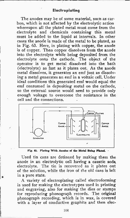
Electroplating
The anodes may be of some material, such as car-bon, which is not affected by the electrolytic actionwhereupon all the plated metal must come from theelectrolyte and chemicals containing this metalmust be added to the liquid at intervals. In othercases the anode is made of the metal to be plated, asin Fig. 63. Here, in plating with copper, the anodeis of copper. Then copper dissolves from the anodeinto the electrolyte while being deposited from theelectrolyte onto the cathode. The object of theoperator is to get metal dissolved into the bath(electrolyte) as fast as it plates out. As the anodemetal dissolves, it generates an emf just as dissolv-ing a metal generates an emf in a voltaic cell. Underideal conditions this generated emf would equal theemf consumed in depositing metal on the cathode,so the external source would need to provide onlyenough voltage to overcome the resistance in thecell and the connections.
Fig. 63. Plating With Anodes of the Metal Being Plated.
Used tin cans are detinned by making them theanode in an electrolytic cell having a caustic soda,electrolyte. The tin is recovered as it plates outof the solution, while the iron of the old cans is leftin a pure state.
A variety of electroplating called electroformingis used for making the electrotypes used in printingand engraving, also for making the dies or stampsfor reproducing phonograph records. The originalphonograph recording, which is in wax, is coveredwith a layer of conductive graphite and then elec-
108
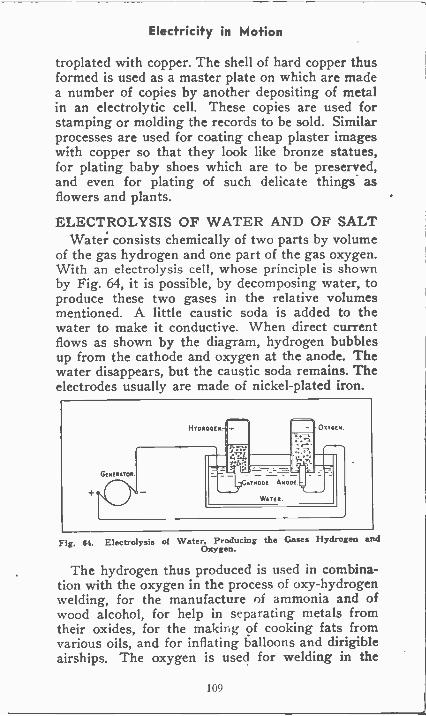
Electricity in Motion
troplated with copper. The shell of hard copper thusformed is used as a master plate on which are madea number of copies by another depositing of metalin an electrolytic cell. These copies are used forstamping or molding the records to be sold. Similarprocesses are used for coating cheap plaster imageswith copper so that they look like bronze statues,for plating baby shoes which are to be preserved,and even for plating of such delicate things asflowers and plants.
ELECTROLYSIS OF WATER AND OF SALTWater consists chemically of two parts by volume
of the gas hydrogen and one part of the gas oxygen.With an electrolysis cell, whose principle is shownby Fig. 64, it is possible, by decomposing water, toproduce these two gases in the relative volumesmentioned. A little caustic soda is added to thewater to make it conductive. When direct currentflows as shown by the diagram, hydrogen bubblesup from the cathode and oxygen at the anode. Thewater disappears, but the caustic soda remains. Theelectrodes usually are made of nickel -plated iron.
Fig. 64. Electrolysis of Water, Producing the Gases Hydrogen andOxygen.
The hydrogen thus produced is used in combina-tion with the oxygen in the process of oxy-hydrogenwelding, for the manufacture of ammonia and ofwood alcohol, for help in separating metals fromtheir oxides, for the making of cooking fats fromvarious oils, and for inflating balloons and dirigibleairships. The oxygen is used for welding in the
109
Electricity in Motion
oxy-acetylene process, and in great amounts fordozens of chemical processes and medicinal uses.
When a water solution of sodium chloride, ordi-nary salt, is decomposed in an electrolytic cell it ispossible to obtain a whole variety of some of themost important chemicals used in commerce andindustry as well as in the home. We obtain causticsoda for use in making soaps, as a cleaning agent,and in various electrolytes. We obtain chlorine foruse in bleaching of cloth, paper and other materials,for use as a disinfectant and for purification of citydrinking water, for use in medicine and in photog-raphy, and for use in certain processes of extractingmetals from their ores. We obtain sodium chloratewhich is used in the manufacture of dyes, medicines,and explosives. Finally, we obtain hydrogen, whoseuses already have been mentioned.
ELECTROLYTIC REFININGIn the processes of electrolytic refining of metals
we start out with an alloy or mixture of metals,which is used as the anode in a cell. The principalmetal to be recovered dissolves into the electrolyte,as do also all other metals which are less "noble".By a noble metal we mean one that resists corro-sion, a form of chemical decomposition. Platinum,gold and iridium are examples of highly noble metals,because they remain unaffected by most acids andother chemicals. Zinc and iron are not noble metals,they are base metals, because they are easily at-tacked by many chemicals. The electrolyte, current,voltage, temperature and the general operating con-ditions are such that the principal metal and thoseless noble pass into the electrolyte, while all thosemore noble remain in the anode.
The principal metal to be recovered is depositedin a pure state on the cathode of the cell. The lessnoble metals remain in the electrolyte where theysink to form the "mud". About nine -tenths of allthe refined copper is produced electrolytically. Gold,silver and arsenic are recovered in the same process.
110
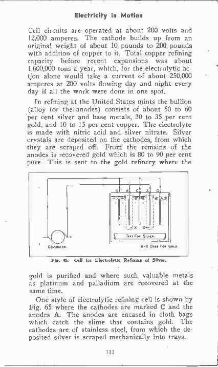
Electricity in Motion
Cell circuits are operated at about 200 volts and12,000 amperes. The cathode builds up from anoriginal weight of about 10 pounds to 200 poundswith addition of copper to it. Total copper refiningcapacity before recent expansions was about1,600,000 tons a year, which, for the electrolytic ac-tion alone would take a current of about 250,000amperes at 200 volts flowing day and night everyday if all the work were done in one spot.
In refining at the United States mints the bullion(alloy for the anodes) consists of about 50 to 60per cent silver and base metals, 30 to 35 per centgold, and 10 to 15 per cent copper. The electrolyteis made with nitric acid and silver nitrate. Silvercrystals are deposited on the cathodes, from whichthey are scraped off. From the remains of theanodes is recovered gold which is 80 to 90 per centpure. This is sent to the gold refinery where the
Fig. U. Cell for Electrolytic Refining of Silver.
gold is purified and where such valuable metalsas platinum and palladium are recovered at thesame time.
One style of electrolytic refining cell is shown byFig. 65 where the cathodes are marked C and theanodes A. The anodes are encased in cloth bagswhich catch the slime that contains gold. Thecathodes are of stainless steel, from which the de-posited silver is scraped mechanically into trays.
111
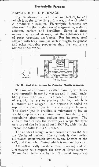
Electrolytic Furnace
ELECTROLYTIC FURNACEFig. 66 shows the action of an electrolytic cell
which is at the same time a furnace, and with whichis produced aluminum. Electrolytic furnaces arealso used for the production of magnesium, sodium,calcium, cerium and beryllium. Some of thesenames may sound strange, but the substances areof great practical usefulness. For instance, steelalloyed with beryllium has such strength, toughnessand other valuable properties that the results arealmost unbelievabe.
GENERATOR
k'FRESN
ALUMINA.
FUSCO CRVOLITE.
a MOLTEN ALUMINUM.
row AarisearmozorezrzA-STEEL CASING.
Fig. gli. Electrolytic Furnace for Producing Metallic Aluminum.
The ore of aluminum is called bauxite, which oc-curs naturally in earthy masses and in small rock-like grains. The bauxite is treated in another kindof electric furnace to produce alumina, which isaluminum and oxygen. This alumina is added ontop of the electrolyte in the electrolytic furnace.The electrolyte is cryolite, a substance of icy orwaxlike appearance coming from Greenland, andcontaining aluminum, sodium and fluorine. Thecurrent that causes the electrolysis keeps the tem-perature of the bath at about 1,800° F., which is thereason for calling this a furnace.
The anodes through which current enters the cellare blocks of carbon. The cathode is the moltenaluminum itself which settles to the bottom of thecell, and the carbon lining which is encased by steel.
All voltaic cells produce direct current and allelectrolytic cells require the flow of direct current.These two fields are by far the most important
112
Electrolytic Furnace
present uses of direct current. The other great fieldsof electricty require the use of alternating current,with which we now shall prepare to get acquainted.As the first step in this preparation we 'shall studymagnetism and electromagnetism in the followingsection. It is the combination of magnetism and theelectric current that is the foundation of all alternat-ing -current applications and also of some direct-current applications which we still have to in-vestigate.
113
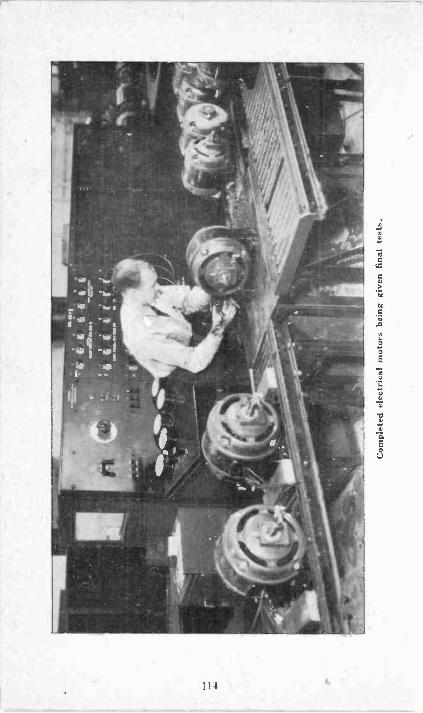
Com
plet
ed e
lect
rica
l mot
ors
bein
g gi
ven
fina
l tes
ts.
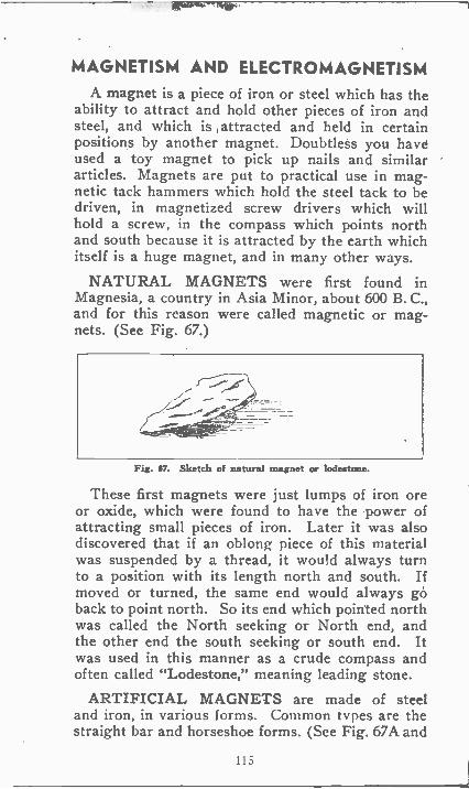
MAGNETISM AND ELECTROMAGNETISMA magnet is a piece of iron or steel which has the
ability to attract and hold other pieces of iron andsteel, and which is attracted and held in certainpositions by another magnet. Doubtless you haveused a toy magnet to pick up nails and similararticles. Magnets are put to practical use in mag-netic tack hammers which hold the steel tack to bedriven, in magnetized screw drivers which willhold a screw, in the compass which points northand south because it is attracted by the earth whichitself is a huge magnet, and in many other ways.
NATURAL MAGNETS were first found inMagnesia, a country in Asia Minor, about 600 B. C.,and for this reason were called magnetic or mag-nets. (See Fig. 67.)
Fig. Si. Sketch of natural magnet or lodestone.
These first magnets were just lumps of iron oreor oxide, which were found to have the power ofattracting small pieces of iron. Later it was alsodiscovered that if an oblong piece of this materialwas suspended by a thread, it would always turnto a position with its length north and south. Ifmoved or turned, the same end would always goback to point north. So its end which pointed northwas called the North seeking or North end, andthe other end the south seeking or south end. Itwas used in this manner as a crude compass andoften called "Lodestone," meaning leading stone.
ARTIFICIAL MAGNETS are made of steeland iron, in various forms. Common types are thestraight bar and horseshoe forms. (See Fig. 67A and
115
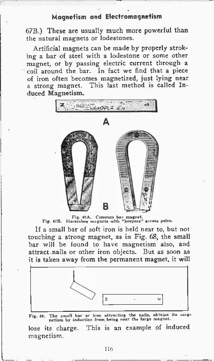
Magnetism and Electromagnetism
67B.) These are usually much more powerful thanthe natural magnets or lodestones.
Artificial magnets can be made by properly strok-ing a bar of steel with a lodestone or some othermagnet, or by passing electric current through acoil around the bar. In fact we find that a pieceof iron often becomes magnetized, just lying neara strong magnet. This last method is called In-duced Magnetism.
A
BFig. 67A. Common bar magnet.
Fig. 67B. Horseshoe magnets with "keepers" across poles.
If a small bar of soft iron is held near to, but nottouching a strong magnet, as in Fig. 68, the smallbar will be found to have magnetism also, andattract nails or other iron objects. But as soon asit is taken away from the permanent magnet, it will
Fig. 68. The small bar or iron attracting the nails, obtains its "lag-netism by induction from being near the large magnet.
lose its charge. This is an example of inducedmagnetism.
116
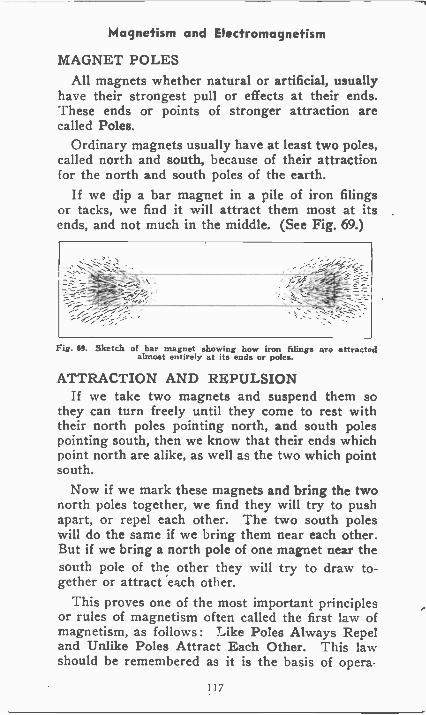
Magnetism and Electromagnetism
MAGNET POLESAll magnets whether natural or artificial, usually
have their strongest pull or effects at their ends.These ends or points of stronger attraction arecalled Poles.
Ordinary magnets usually have at least two poles,called north and south, because of their attractionfor the north and south poles of the earth.
If we dip a bar magnet in a pile of iron filingsor tacks, we find it will attract them most at itsends, and not much in the middle. (See Fig. 69.)
Fig. 69. Sketch of bar magnet showing how iron filings are attractedalmost entirely at its ends or poles.
ATTRACTION AND REPULSIONIf we take two magnets and suspend them so
they can turn freely until they come to rest withtheir north poles pointing north, and south polespointing south, then we know that their ends whichpoint north are alike, as well as the two which pointsouth.
Now if we mark these magnets and bring the twonorth poles together, we find they will try to pushapart, or repel each other. The two south poleswill do the same if we bring them near each other.But if we bring a north pole of one magnet near thesouth pole of the other they will try to draw to-gether or attract each other.
This proves one of the most important principlesor rules of magnetism often called the first law ofmagnetism, as follows : Like Poles Always Repeland Unlike Poles Attract Each Other. This lawshould be remembered as it is the basis of opera -
117
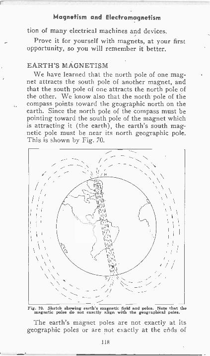
Magnetism and Electromagnetism
tion of many electrical machines and devices.Prove it for yourself with magnets, at your first
opportunity, so you will remember it better.
EARTH'S MAGNETISMWe have learned that the north pole of one mag-
net attracts the south pole of another magnet, andthat the south pole of one attracts the north pole ofthe other. We know also that the north pole of thecompass points toward the geographic north on theearth. Since the north pole of the compass must bepointing toward the south pole of the magnet whichis attracting it (the earth), the earth's south mag-netic pole must be near its north geographic pole.This is shown by Fig. 70.
Fig. 70. Sketch showing earth's magnetic field and poles. Note that themagnetic poles do not exactly align with the geographical poles.
The earth's magnet poles are not exactly at itsgeographic poles or are not exactly at the ends of
118
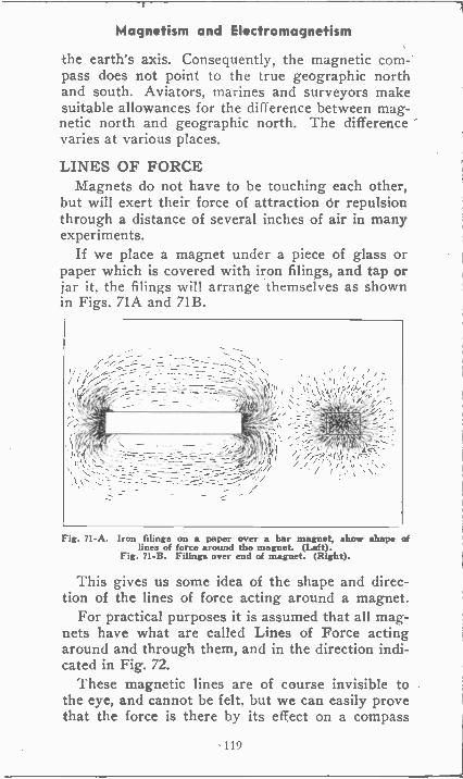
Magnetism and Electromagnetism
-the earth's axis. Consequently, the magnetic com-pass does not point to the true geographic northand south. Aviators, marines and surveyors makesuitable allowances for the difference between mag-netic north and geographic north. The differencevaries at various places.
LINES OF FORCEMagnets do not have to be touching each other,
but will exert their force of attraction dr repulsionthrough a distance of several inches of air in manyexperiments.
If we place a magnet under a piece of glass orpaper which is covered with iron filings, and tap orjar it, the filings will arrange themselves as shownin Figs. 71A and 71B.
Fig. 71-A. Iron filings on a paper over a bar magnet, show shape oflines of force around the magnet. (Left).
Fig. 71-B. Filings over end of magnet. (Right).
This gives us some idea of the shape and direc-tion of the lines of force acting around a magnet.
For practical purposes it is assumed that all mag-nets have what are called Lines of Force actingaround and through them, and in the direction indi-cated in Fig. 72.
These magnetic lines are of course invisible tothe eye, and cannot be felt, but we can easily provethat the force is there by its effect on a compass
119
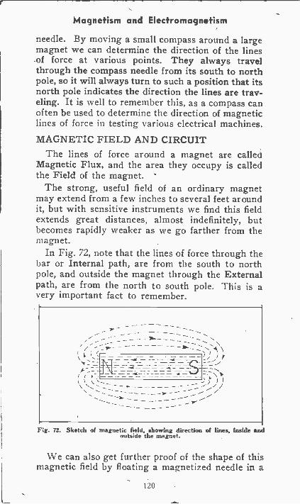
Magnetism and Electromagnetism
needle. By moving a small compass around a largemagnet we can determine the direction of the lines-of force at various points. They always travelthrough the compass needle from its south to northpole, so it will always turn to such a position that itsnorth pole indicates the direction the lines are trav-eling. It is well to remember this, as a compass canoften be used to determine the direction of magneticlines of force in testing various electrical machines.
MAGNETIC FIELD AND CIRCUITThe lines of force around a magnet are called
Magnetic Flux, and the area they occupy is calledthe Field of the magnet.
The strong, useful field of an ordinary magnetmay extend from a few inches to several feet aroundit, but with sensitive instruments we find this fieldextends great distances, almost indefinitely, butbecomes rapidly weaker as we go farther from themagnet.
In Fig. 72, note that the lines of force through thebar or Internal path, are from the south to northpole, and outside the magnet through the Externalpath, are from the north to south pole. This is avery important fact to remember.
Fig. 72. Sketch of magnetic field, showing direction of lines, Inside andoutside the magnet.
We can also get further proof of the shape of thismagnetic field by floating a magnetized needle in a
120
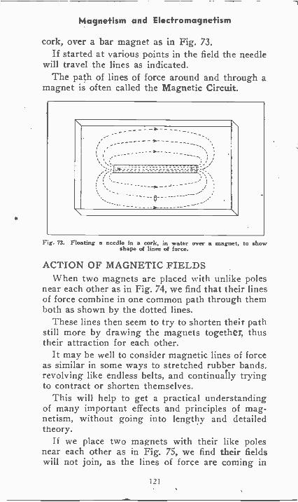
Magnetism and Electromagnetism
cork, over a bar magnet as in Fig. 73.If started at various points in the field the needle
will travel the lines as indicated.The path of lines of force around and through a
magnet is often called the Magnetic Circuit.
\ \t i ,
...----\
Fig. 73. Floating a needle in a cork, in water over a magnet, to showshape of lines of force.
ACTION OF MAGNETIC FIELDSWhen two magnets are placed with unlike poles
near each other as in Fig. 74, we find that their linesof force combine in one common path through themboth as shown by the dotted lines.
These lines then seem to try to shorten their pathstill more by drawing the magnets together, thustheir attraction for each other.
It may be well to consider magnetic lines of forceas similar in some ways to stretched rubber bands.revolving like endless belts, and continually tryingto contract or shorten themselves.
This will help to get a practical understandingof many important effects and principles of mag-netism, without going into lengthy and detailedtheory.
If we place two magnets with their like polesnear each other as in Fig. 75, we find their fieldswill not join, as the lines of force are coming in
121
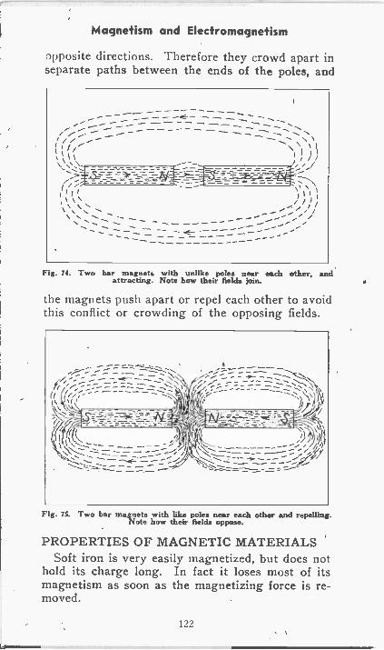
Magnetism and Electromagnetism
opposite directions. Therefore they crowd apart inseparate paths between the ends of the poles, and
Fig. 74. Two bar magnets with unlike poles near each other. andattracting. Note how their fields join.
the magnets push apart or repel each other to avoidthis conflict or crowding of the opposing fields.
Fig. 75. Two bar magnets with like poles near each other and repelling.Note how their fields oppose.
PROPERTIES OF MAGNETIC MATERIALSSoft iron is very easily magnetized, but does not
hold its charge long. In fact it loses most of itsmagnetism as soon as the magnetizing force is re-moved.
122
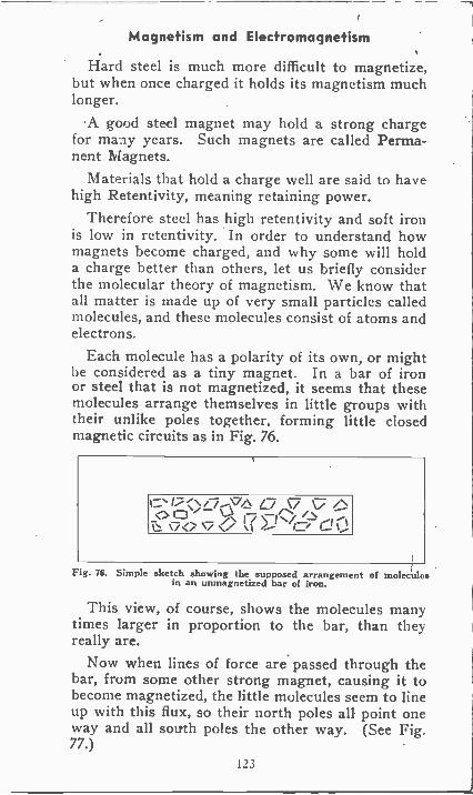
Magnetism and Electromagnetism
Hard steel is much more difficult to magnetize,but when once charged it holds its magnetism muchlonger.
A good steel magnet may hold a strong chargefor many years. Such magnets are called Perma-nent Magnets.
Materials that hold a charge well are said to havehigh Retentivity, meaning retaining power.
Therefore steel has high retentivity and soft ironis low in retentivity. In order to understand howmagnets become charged, and why some will holda charge better than others, let us briefly considerthe molecular theory of magnetism. We know thatall matter is made up of very small particles calledmolecules, and these molecules consist of atoms andelectrons.
Each molecule has a polarity of its own, or mightbe considered as a tiny magnet. In a bar of ironor steel that is not magnetized, it seems that thesemolecules arrange themselves in little groups withtheir unlike poles together, forming little closedmagnetic circuits as in Fig. 76.
< /-7 --VA as-> c -if***- q, .s>
\-7<> 7</ % ...1
Fig. 76. Simple sketch showing the supposed arrangement of moleculesin an unmagnetized bar of iron.
This view, of course, shows the molecules manytimes larger in proportion to the bar, than theyreally are.
Now when lines of force are passed through thebar, from some other strong magnet, causing it tobecome magnetized, the little molecules seem to lineup with this flux, so their north poles all point oneway and all south poles the other way. (See Fig.77.)
123
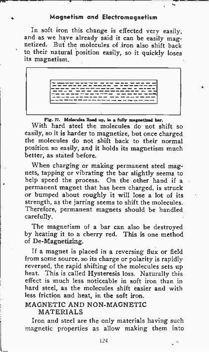
Magnetism and Electromagnetism
In soft iron this change is effected very easily,and as we have already said it can be easily mag-netized. But the molecules of iron also shift backto their natural position easily, so it quickly losesits magnetism.
Fig. 77. Molecules lined up. in a fully magnetized bar.With hard steel the molecules do not shift so
easily, so it is harder to magnetize, but once chargedthe molecules do not shift back to their normalposition so easily, and it holds its magnetism muchbetter, as stated before.
When charging or making permanent steel mag-nets, tapping or vibrating the bar slightly seems tohelp speed the process. On the other hand if apermanent magnet that has been charged, is struckor bumped about roughly it will lose a lot of itsstrength, as the jarring seems to shift the molecules.Therefore, permanent magnets should be handledcarefully.
The magnetism of a bar can also be destroyedby heating it to a cherry red. This is one methodof De -Magnetizing.
If a magnet is placed in a reversing flux or fieldfrom some source, so its charge or polarity is rapidlyreversed, the rapid shifting of the molecules sets upheat. This is called Hysteresis loss. Naturally thiseffect is much less noticeable in soft iron than inhard steel, as the molecules shift easier and withless friction and heat, in the soft iron.MAGNETIC AND NON-MAGNETIC
MATERIALSIron and steel are the only materials having such
magnetic properties as allow making them into
124
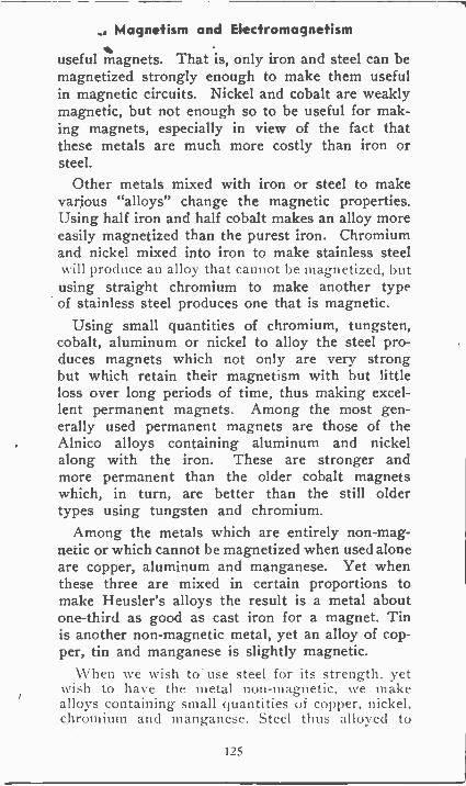
. Magnetism and Electromagnetism
useful magnets. That is, only iron and steel can bemagnetized strongly enough to make them usefulin magnetic circuits. Nickel and cobalt are weaklymagnetic, but not enough so to be useful for mak-ing magnets, especially in view of the fact thatthese metals are much more costly than iron orsteel.
Other metals mixed with iron or steel to makevarious "alloys" change the magnetic properties.Using half iron and half cobalt makes an alloy moreeasily magnetized than the purest iron. Chromiumand nickel mixed into iron to make stainless steelNvill produce an alloy that cannot he magnetized, hutusing straight chromium to make another typeof stainless steel produces one that is magnetic.
Using small quantities of chromium, tungsten,cobalt, aluminum or nickel to alloy the steel pro-duces magnets which not only are very strongbut which retain their magnetism with but littleloss over long periods of time, thus making excel-lent permanent magnets. Among the most gen-erally used permanent magnets are those of theAlnico alloys containing aluminum and nickelalong with the iron. These are stronger andmore permanent than the older cobalt magnetswhich, in turn, are better than the still oldertypes using tungsten and chromium.
Among the metals which are entirely non-mag-netic or which cannot be magnetized when used aloneare copper, aluminum and manganese. Yet whenthese three are mixed in certain proportions tomake Heusler's alloys the result is a metal aboutone-third as good as cast iron for a magnet. Tinis another non-magnetic metal, yet an alloy of cop-per, tin and manganese is slightly magnetic.
-When we wish to. use steel for its strength, yetwish to have the metal non-magnetic, we makealloys containing small quantities of copper, nickel.chromium and manganese. Steel thus alloyed to
125
Magnetism and Electromagnetism
be non-magnetic is called paramagnetic.Antimony and bismuth act very peculiarly. The
stronger the magnetic field in which these metalsare placed the fewer lines of force travel throughthe antimony or bismuth. These metals are saidto be diamagnetic.
All materials which have not been mentioned inthe preceding paragraphs are wholly non-mag-netic. They canot be magnetized and they havenot the slightest effect on a magnetic field in whichthey are placed. The non-magnetic materials in-clude air and all other gases, all the liquids, allmetals not already mentioned, and all other solidsubstances such as glass, wood, paper and so on.
PERMEABILITY AND RELUCTANCEExperiments prove that magnetic lines of force
will pass through iron and steel, or magnetic mate-rials much easier than through air, wood and brass,or non-magnetic materials of any kind. So iron andsteel form a good path for magnetic flux, and aresaid to have high Permeability, and low Reluctance.The term reluctance means the same to magneticflux as resistance means to electric current.
Fig. isA & B. Sketches showing how lines of force can be distortedand made to follow the easier path through the small
iron bars.
I f e place a small bar of soft iron in the field ofa larger magnet as in Fig. 78A or near the ends oftwo magnets as in Fig. 78B, in both cases the linesof force will largely choose the easier path through
126
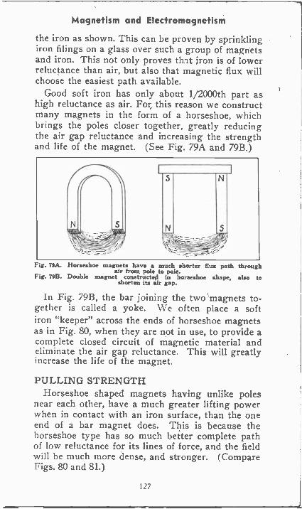
Magnetism and Electromagnetism
the iron as shown. This can be proven by sprinklingiron filings on a glass over such a group of magnetsand iron. This not only proves that iron is of lowerreluctance than air, but also that magnetic flux willchoose the easiest path available.
Good soft iron has only about 1/2000th part ashigh reluctance as air. For this reason we constructmany magnets in the form of a horseshoe, whichbrings the poles closer together, greatly reducingthe air gap reluctance and increasing the strengthand life of the magnet. (See Fig. 79A and 79B.)
Fig. 79A. Horseshoe magnets have a much shorter flux path throughair from pole to pole.
Fig. 79B. Double magnet constructed in horseshoe shape, also toshorten its air gap.
In Fig. 79B, the bar joining the two magnets to-gether is called a yoke. We often place a softiron "keeper" across the ends of horseshoe magnetsas in Fig. 80, when they are not in use, to provide acomplete closed circuit of magnetic material andeliminate the air gap reluctance. This will greatlyincrease the life of the magnet.
PULLING STRENGTHHorseshoe shaped magnets having unlike poles
near each other, have a much greater lifting powerwhen in contact with an iron surface, than the oneend of a bar magnet does. This is because thehorseshoe type has so much better complete pathof low reluctance for its lines of force, and the fieldwill be much more dense, and stronger. (CompareFigs. 80 and 81.)
127
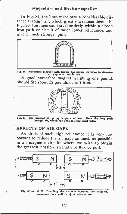
Magnetism and Electromagnetism
In Fig. 81, the lines must pass a considerable dis-tance through air, which greatly weakens them. InFig. 80, the lines can travel entirely within a closediron path or circuit of much lower reluctance, andgive a much stronger pull.
Fig. 80. Horseshoe magnet with keeper bar across its poles to decreaseair gap when not in use.
A good horseshoe magnet weighing one pound,should lift about 25 pounds of soft iron.
Fig. Si. Bar magnet attracting a piece of iron. Note the long paththrough air, which the lines of force must take.
EFFECTS OF AIR GAPSAs air is of such high reluctance it is very im-
portant to reduce the air gaps as much as possiblein all magnetic circuits where we wish to obtainthe greatest possible strength of flux or pull.
N 15 Na 0
N 5 1-0-L=J-°I ft
1 -,1
Fig. 82.-A. & B. Doubling the distance between two magnets,decreases their pull to 1/4 of what it was.
128
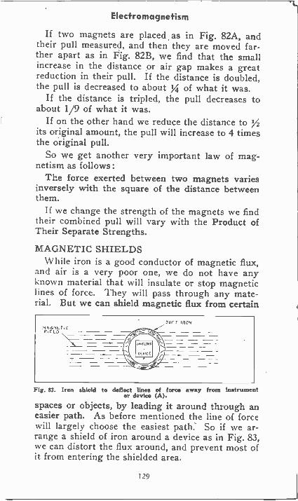
Electromagnetism
If two magnets are placed as in Fig. 82A, andtheir pull measured, and then they are moved far-ther apart as in Fig. 82B, we find that the smallincrease in the distance or air gap makes a greatreduction in their pull. If the distance is doubled,the pull is decreased to about XI of what it was.
If the distance is tripled, the pull decreases toabout 1/9 of what it was.
If on the other hand we reduce the distance to 72its original amount, the pull will increase to 4 timesthe original pull.
So we get another very important law of mag-netism as follows:
The force exerted between two magnets variesinversely with the square of the distance betweenthem.
If we change the strength of the magnets we findtheir combined pull will vary with the Product ofTheir Separate Strengths.
MAGNETIC SHIELDSWhile iron is a good conductor of magnetic flux,
and air is a very poor one, we do not have anyknown material that will insulate or stop magneticlines of force. They will pass through any mate-rial. But we can shield magnetic flux from certain
SOFT IRONMAGNETICFIELD
Fig. 83. Iron shield to deflect lines of force away from Instrumentor device (A).
spaces or objects, by leading it around through aneasier path. As before mentioned the line of forcewill largely choose the easiest path. So if we ar-range a shield of iron around a device as in Fig. 83,we can distort the flux around, and prevent most ofit from entering the shielded area.
129
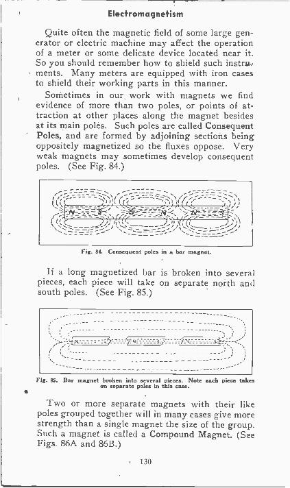
Electromagnetism
Quite often the magnetic field of some large gen-erator or electric machine may affect the operationof a meter or some delicate device located near it.So you should remember how to shield such instruments. Many meters are equipped with iron casesto shield their working parts in this manner.
Sometimes in our work with magnets we findevidence of more than two poles, or points of at-traction at other places along the magnet besidesat its main poles. Such poles are called ConsequentPoles, and are formed by adjoining sections beingoppositely magnetized so the fluxes oppose. Veryweak magnets may sometimes develop consequentpoles. (See Fig. 84.)
Z- -------- - -if?
"Pe-
Fig. 84. Consequent poles in a bar magnet.
If a long magnetized bar is broken into severalpieces, each piece will take on separate north andsouth poles. (See Fig. 85.)
Fig. 8S. Bar magnet broken into several pieces. Note each piece takeson separate poles in this case.
Two or more separate magnets with their likepoles grouped together will in many cases give morestrength than a single magnet the size of the group.Such a magnet is called a Compound Magnet. (SeeFigs. 86A and 86B.)
130
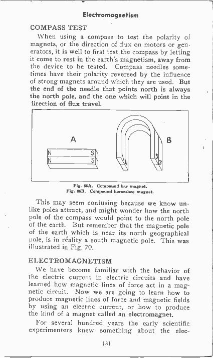
Electromagnetism
COMPASS TESTWhen using a compass to test the polarity of
magnets, or the direction of flux on motors or gen-erators, it is well to first test the compass by lettingit come to rest in the earth's magnetism, away fromthe device to be tested. Compass needles some-times have their polarity reversed by the influenceof strong magnets around which they are used. Butthe end of the needle that points north is alwaysthe north pole, and the one which will point in thelirection of flux travel.
Fig. 86A. Compound bar magnet.Fig. 86B. Compound horseshoe magnet.
This may seem confusing because we know un-like poles attract, and might wonder how the northpole of the compass would point to the north poleof the earth. But remember that the magnetic poleof the earth which is near its north geographicalpole, is in reality a south magnetic pole. This wasillustrated in Fig. 70.
ELECTROMAGNETISMWe have become familiar with the behavior of
the electric current in electric circuits and havelearned how magnetic lines of force act in a mag-netic circuit. Now we are going to learn how toproduce magnetic lines of force and magnetic fieldsby using an electric current, or how to producethe kind of a magnet called an electromagnet.
For several hundred years the early scientificexperimenters knew something about the elec-
131
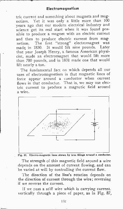
Electromagnetism
tric current and something about magnets and mag-netism. Yet it was only a little more than 100years ago that our modern electrical industry andscience got its real start when it was found pos-sible to produce a magnet with an electric currentand then to produce electric current from mag-netism. The first "strong" electromagnet wasmade in 1830. It would lift nine pounds. Laterthat year Joseph Henry, a famous American physi-cist, made an electromagnet that would lift morethan 700 pounds, and in 1831 made one that wouldlift nearly a ton.
The fundamental fact on which depends all ouruses of electromagnetism is that magnetic lines offorce appear around a conductor when currentflows in that conductor. That is, we may use elec-tric current to produce a magnetic field arounda wire.
Fig. 87. Electro-magnetic lines shown by iron filings around a conductor.
The strength of this magnetic field around a wiredepends on the amount of current flowing, and canbe varied at will by controlling the current flow.
The direction of the line's rotation depends onthe direction of current through the wire; reversingif we reverse the current.
If we pass a stiff wire which is carrying current,vertically through a piece of paper, as in Fig. 87,
132
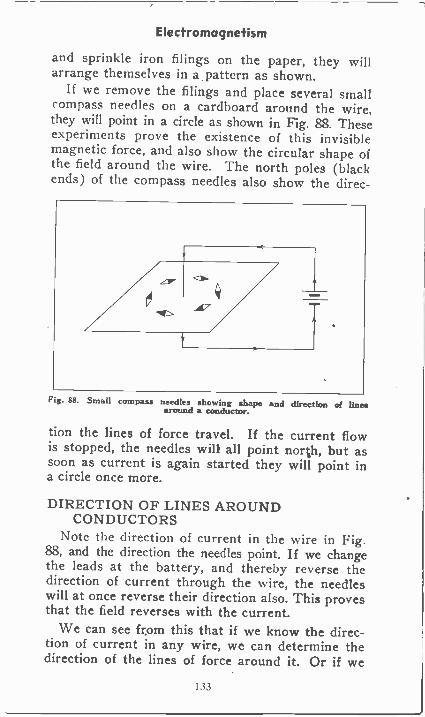
Electromagnetism
and sprinkle iron filings on the paper, they willarrange themselves in a pattern as shown.
If we remove the filings and place several smallcompass needles on a cardboard around the wire,they will point in a circle as shown in Fig. 88. Theseexperiments prove the existence of this invisiblemagnetic force, and also show the circular shape ofthe field around the wire. The north poles (blackends) of the compass needles also show the direc-
Fig. 88. Small compass needles showing shape and direction of linesaround a conductor.
tion the lines of force travel. If the current flowis stopped, the needles will all point north, but assoon as current is again started they will point ina circle once more.
DIRECTION OF LINES AROUNDCONDUCTORS
Note the direction of current in the wire in Fig.88, and the direction the needles point. If we changethe leads at the battery, and thereby reverse thedirection of current through the wire, the needleswill at once reverse their direction also. This provesthat the field reverses with the current.
We can see from this that if we know the direc-tion of current in any wire, we can determine thedirection of the lines of force around it. Or if we
I33
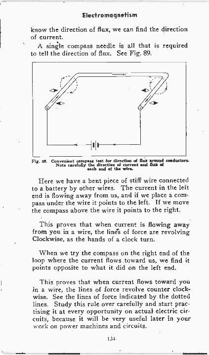
Electromagnetism
know the direction of flux, we can find the directionof current.
A single compass needle is all that is requiredto tell the direction of flux. See Fig. 89.
Fig. 89. Convenient compass test for direction of flux around conductors.Note carefully the direction of current and flux of
each end of the wire.
Here we have a bent piece of stiff wire connectedto a battery by other wires. The current in the leftend is flowing away from us, and if we place a com-pass under the wire it points to the left. If we movethe compass above the wire it points to the right.
This proves that when current is flowing awayfrom you in a wire, the lines of force are revolvingClockwise, as the hands of a clock turn.
When we try the compass on the right end of theloop where the current flows toward us, we find itpoints opposite to what it did on the left end.
This proves that when current flows toward youin a wire, the lines of force revolve counter clock-wise. See the lines of force indicated by the dottedlines. Study this rule over carefully and start prac-tising it at every opportunity on actual electric cir-cuits, because it will be very useful later in yourNAork on power machines and circuits.
134
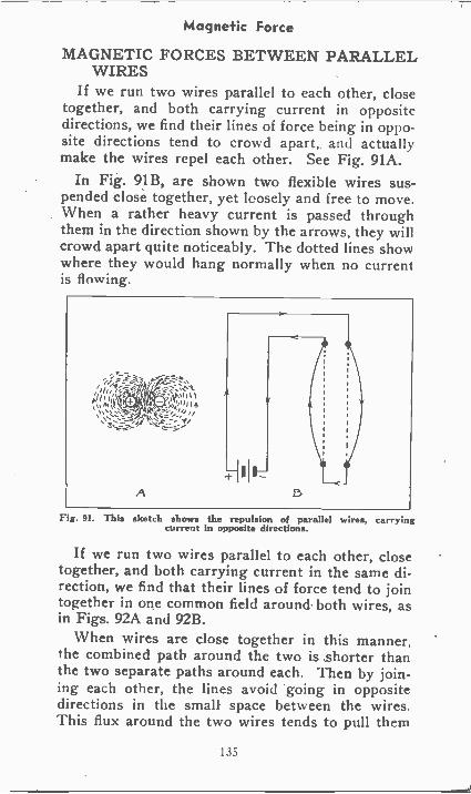
Magnetic Force
MAGNETIC FORCES BETWEEN PARALLELWIRES
If we run two wires parallel to each other, closetogether, and both carrying current in oppositedirections, we find their lines of force being in oppo-site directions tend to crowd apart, and actuallymake the wires repel each other. See Fig. 91A.
In Fig. 91B, are shown two flexible wires sus-pended close together, yet loosely and free to move.When a rather heavy current is passed throughthem in the direction shown by the arrows, they willcrowd apart quite noticeably. The dotted lines showwhere they would hang normally when no currentis flowing.
Fig. 91. This sketch shows the repulsion of parallel wires, carryingcurrent in opposite directions.
If we run two wires parallel to each other, closetogether, and both carrying current in the same di-rection, we find that their lines of force tend to jointogether in one common field around. both wires, asin Figs. 92A and 92B.
When wires are close together in this manner,the combined path around the two is shorter thanthe two separate paths around each. Then by join-ing each other, the lines avoid going in oppositedirections in the small space between the wires.This flux around the two wires tends to pull them
135
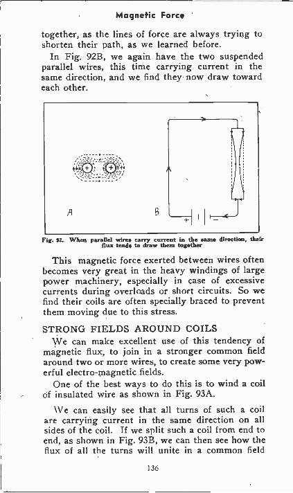
Magnetic Force
together, as the lines of force are always trying toshorten their path, as we learned before.
In Fig. 92B, we again have the two suspendedparallel wires, this time carrying current in thesame direction, and we find they now draw towardeach other.
Fig. 9Z. When parallel wires carry current in the same direction, theirflux tends to draw them together
This magnetic force exerted between wires oftenbecomes very great in the heavy windings of largepower machinery, especially in case of excessivecurrents during overloads or short circuits. So wefind their coils are often specially braced to preventthem moving due to this stress.
STRONG FIELDS AROUND COILSWe can make excellent use of this tendency of
magnetic flux, to join in a stronger common fieldaround two or more wires, to create some very pow-erful electro-magnetic fields.
One of the best ways to do this is to wind a coilof insulated wire as shown in Fig. 93A.
We can easily see that all turns of such a coilare carrying current in the same direction on allsides of the coil. If we split such a coil from end toend, as shown in Fig. 93B, we can then see how theflux of all the turns will unite in a common field
136
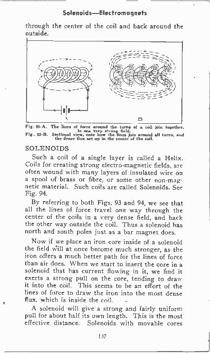
Solenoids-Electromagnets
through the center of the coil and back around theoutside.
--_".:----------""
l'Nto
1, .. . .1 / i\ ." --- ___ --ft" i
,..."--- --.-_-- _ ...- ...... ..,
Fig. 93-A. The lines of force around the turns of a coil join together,in one very strong field.
Fig.. 93-B. Sectional view, note how the lines join around all turns, andthe dense flux set up in the center of the coil.
SOLENOIDSSuch a coil of a single layer is called a Helix.
Coils for creating strong electro-magnetic fields, areoften wound with many layers of insulated wire ona spool of brass or fibre, or some other non-mag-netic material. Such coils are called Solenoids. SeeFig. 94.
By referring to both Figs. 93 and 94, we see thatall the lines of force travel one way through thecenter of the coils in a very dense field, and backthe other way outside the coil. Thus a solenoid hasnorth and south poles just as a bar magnet does.
Now if we place an iron core inside of a solenoidthe field will at once become much stronger, as theiron offers a much better path for the lines of forcethan air does. When we start to insert the core in asolenoid that has current flowing in it, we find itexerts a strong pull on the core, tending to drawit into the coil. This seems to be an effort of thelines of force to draw the iron into the most denseflux. which is inside the coil.
A solenoid will give a strong and fairly uniformpull for about half its own length. This is the mosteffective distance. Solenoids with movable cores
137
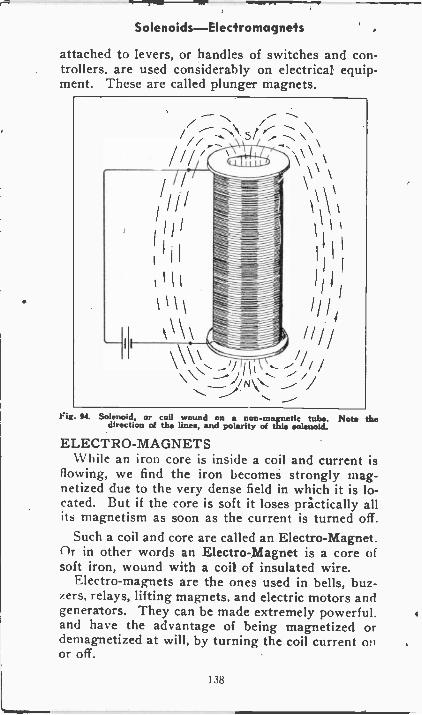
Solenoids-Electromagnets
attached to levers, or handles of switches and con-trollers, are used considerably on electrical equip-ment. These are called plunger magnets.
Fig. 94. Solenoid, or coil wound on a non-magnetic tube. Note thedirection of the lines, and polarity of this solenoid.
ELECTRO-MAGNETS\V hile an iron core is inside a coil and current is
flowing, we find the iron becomes strongly mag-netized due to the very dense field in which it is lo-cated. But if the core is soft it loses practically allits magnetism as soon as the current is turned off.
Such a coil and core are called an Electro-Magnet.flr in other words an Electro-Magnet is a core ofsoft iron, wound with a coil of insulated wire.
Electro-magnets are the ones used in bells, buz-zers, relays, lifting magnets. and electric motors andgenerators. They can be made extremely powerful.and have the advantage of being magnetized ordemagnetized at will, by turning the coil current onor off.
138
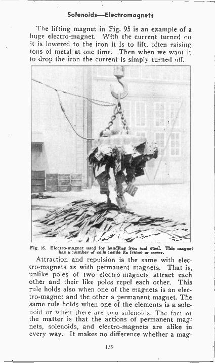
Solenoids-Electromagnets
The lifting magnet in Fig. 95 is an example of ahuge electro-magnet. With the current turned onit is lowered to the iron it is to lift, often raisingtons of metal at one time. Then when we want itto drop the iron the current is simply turned off
Fig. 95. Electro-magnet used for handling iron and steel. This magnethas a number of coils inside its frame or cover.
Attraction and repulsion is the same with elec-tro-magnets as with permanent magnets. That is,unlike poles of two electro-magnets attract eachother and their like poles repel each other. Thisrule holds also when one of the magnets is an elec-tro-magnet and the other a permanent magnet. Thesame rule holds when one of the elements is a sole-noid or \\ hen there are t\N o solenoid,. The fact ofthe matter is that the actions of permanent mag-nets, solenoids, and electro-magnets are alike inevery way. It makes no difference whether a mag-
1 39
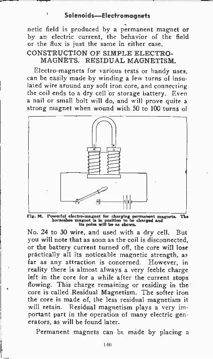
Solenoids-Electromagnets
netic field is produced by a permanent magnet orby an electric current, the behavior of the fieldor the flux is just the same in either case.CONSTRUCTION OF SIMPLE ELECTRO-
MAGNETS. RESIDUAL MAGNETISM.Electro-magnets for various tests or handy uses,
can be easily made by winding a few turns of insu-lated wire around any soft iron core, and connectingthe coil ends to a dry cell 'or storage battery. Evena nail or small bolt will do, and will prove quite astrong magnet when wound with 50 to 100 turns of
Fig. Powerful electromagnet for charging permanent magnets. Thehorseshoe magnet Is in position to be charged and
its poles will be as shown.
No. 24 to 30 wire, and used with a dry cell. Butyou will note that as soon as the coil is disconnected,or the battery current turned off, the core will losepractically all its noticeable magnetic strength, asfar as any attraction is concerned. However, inreality there is almost always a very feeble chargeleft in the core for a while after the current stopsflowing. This charge remaining or residing in thecore is called Residual Magnetism. The softer ironthe core is made of, the less residual magnetism itwill retain. Residual magnetism plays a very im-portant part in the operation of many electric gen-erators, as will be found later.
Permanent magnets can bt made by placing a
140
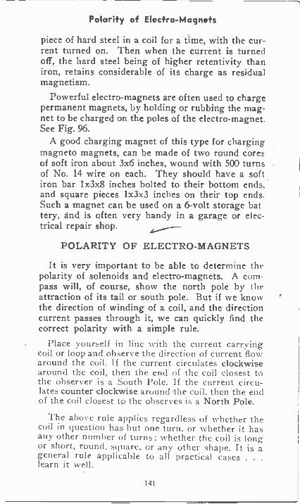
Polarity of Electro-Magnets
piece of hard steel in a coil for a time, with the cur-rent turned on. Then when the current is turnedoff, the hard steel being of higher retentivity thaniron, retains considerable of its charge as residualmagnetism.
Powerful electro-magnets are often used to chargepermanent magnets, by holding or rubbing the mag-net to be charged on the poles of the electro-magnet.See Fig. 96.
A good charging magnet of this type for chargingmagneto magnets, can be made of two round coresof soft iron about 3x6 inches, wound with 500 turnsof No. 14 wire on each. They should have a softiron bar 1 x3x8 inches bolted to their bottom ends,and square pieces 1x3x3 inches on their top ends.Such a magnet can be used on a 6 -volt storage battery, and is often very handy in a garage or elec-trical repair shop.
POLARITY OF ELECTRO-MAGNETS
It is very important to be able to determine thepolarity of solenoids and electro-magnets. A compass will, of course, show the north pole by theattraction of its tail or south pole. But if we knowthe direction of winding of a coil, and the directioncurrent passes through it, we can quickly find thecorrect polarity with a simple rule.
Place yourself in line with the current carryingcoil or loop and observe the direction of current flowaround the coil. If the current circulates clockwisearound the coil, then the end of the coil closest tothe observer is a South Pole. If the current circu-lates counter clockwise around -the coil, then the endof the coil closest to the observes is a North Pole.
The above rule applies regardless of whether thecoil in question has but one turn, or whether it hasany other number of turns ; whether the coil is longor short, round, square, or any other shape. It is ageneral rule applicable to all practical cases . . .
learn it well.
141
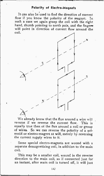
Polarity of Electro-Magnets
It can also be used to find the direction of currentflow if you know the polarity of the magnet. Insuch a case we again grasp the coil with the righthand, thumb pointing to north pole, and the fingers'will point in direction of current flow around thecoil.
S
S
We already know that the flux around a wire willreverse if we reverse the current flow. This isequally true then of the flux around a coil or groupof wires. So we can reverse the polarity of a sol-enoid or electro-magnet at will, merely by reversingthe current supply wires to it.
Some special electro-magnets are wound with aseparate demagnetizing coil, in addition to the maincoil.
This may be a smaller coil, wound in the reversedirection to the main coil, so if connected just foran instant, after main coil is turned off, it will just
142
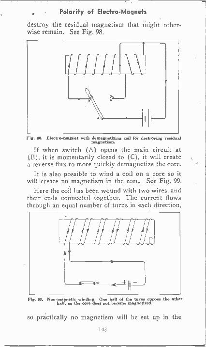
Polarity of Electro-Magnets
destroy the residual magnetism that might other-wise remain. See Fig. 98.
Fig. 99. Electro-magnet with demagnetizing coil for destroying residualmagnetism.
If when switch (A) opens the main circuit at(,B), it is momentarily closed to (C), it will createa reverse flux to more quickly demagnetize the core.
It is also possible to wind a coil on a core so itwill create no magnetism in the core. See Fig. 99.
I Jere the coil has been wound with two wires, andtheir ends connected together. The current flowsthrough an equal number of turns in each direction,
Fig. 99. Non-magnetic winding. One half of the turns oppose the otherhalf, so the core does not become magnetized.
so practically no magnetism will be set up in the
143
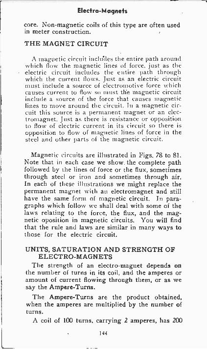
Elecfro-Magnefs
core. Non-magnetic coils of this type are often usedin meter construction.
THE MAGNET CIRCUIT
A magnetic circuit includes the entire path aroundwhich flow the magnetic lines of force, just as theelectric circuit includes the entire path throughwhich the current flows. Just as an electric circuitmust include a source of electromotive force whichcauses current to flow so must the magnetic circuitinclude a source of the force that causes magneticlines to move around the circuit. In a magnetic cir-cuit this source is a permanent magnet or an elec-tromagnet. Just as there is resistance or oppositionto flow of electric current in its circuit so there isopposition to flow of magnetic lines of force in thesteel and other parts of the magnetic circuit.
Magnetic circuits are illustrated in Figs. 78 to 81.Note that in each case we show the complete pathfollowed by the lines of force or the flux, sometimesthrough steel or iron and sometimes through air.In each of these illustrations we might replace thepermanent magnet with an electromagnet and stillhave the same form of magnetic circuit. In para-graphs which follow we shall deal with some of thelaws relating to the force, the flux, and the mag-netic oposition in magnetic circuits. You will findthat the rule and laws are similar in many ways tothose for the electric circuit.
UNITS, SATURATION AND STRENGTH OFELECTRO-MAGNETS
The strength of an electro-magnet depends onthe number of turns in its coil, and the amperes oramount of current flowing through them, or as wesay the Ampere -Turns.
The Ampere -Turns are the product obtained,when the amperes are multiplied by the number ofturns.
A coil of 100 turns, carrying 2 amperes, has 200
144
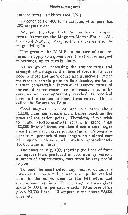
Electro-Magnets
ampere -turns. (Abbreviated I.N.)Another coil of 400 turns carrying 72 ampere, has
200 ampere -turns.
We say therefore that the number of ampereturns, determines the Magneto -Motive -Force. (Ab-breviated M.M.F.) Ampere -turns measure also themagnetizing force.
The greater the M.M.F. or number of ampere -turns we apply to a given core, the stronger magnetit becomes, up to certain limits.
As we go on increasing the ampere -turns andstrength of a magnet, the lines of force in its corebecome more and more dense and numerous. Afterwe reach a certain point in flux density, we find afurther considerable increase of ampere turns ofthe coil, does not cause much increase of flux in thecore, as we have apparently reached its practicallimit in the number of lines it can carry. This iscalled the Saturation -Point.
Good magnetic iron or steel can carry about100,000 lines per square inch, before reaching thepractical saturation point. Therefore, if we wishto make electro-magnets requiring more than100,000 lines of force, we should use a core largerthan 1 square inch cross sectional area. Fifteen am-pere -turns per inch of core length, on a closed coreof 1 square inch area, will produce approximately100,000 lines of force.
The chart in Fig. 100, showing the lines of forceper square inch, produced in soft iron by variousnumbers of ampere -turns, may often be very usefulto you.
To read the chart select any number of ampereturns at the bottom line and run up the verticallines to the curve, then to the left edge, andread number of lines. Thus 5 ampere turns givesabout 67,000 lines per square inch. 10 ampere turnsgives 90,000 lines. 12 ampere turns about 95,000lines, etc.
145
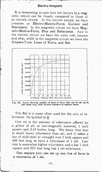
Electra -Magnets
It is interesting to note how the factors in a mag-netic circuit can be closely compared to those ofan electric circuit. In the electric circuit, we havepressure or Electro-Motive-Force, Current andResistance. In the magnetic circuit we have Mag-neto -Motive -Force, Flux and Reluctance. And inthe electric circuit we have the units volt, ampereand ohm, while in the magnetic circuit we have theAmpere -Turn, Lines of Force, and Rel.
2 9000
105,000
i sood
4 76000
O1` 30,000a
16.090
6.60,000o_
45,000
0 5 10 15 20 26 20 26 40 46AMPERE TURNS PER INCH OF LENGTH
Fig. 100. Curve showing number of lines of force that can be set up insoft sheet iron, with various numbers of ampere turns.
The Rel is a name often used for the unit of re-luctance. Its symbol is ,R
One rel is the amount of reluctance offered bya prism of air or non-magnetic material, 1 inchsquare and 3.19 inches long. We know that ironis much lower reluctance than air, and it takes abar of mild steel or wrought iron 1 inch square and460 feet long to have a reluctance of 1 rel. Castiron is somewhat higher reluctance, and a bar 1 inchsquare and 50.7 feet long has 1 rel reluctance.
One ampere turn can set up one line of force ina reluctance of 1 rd.
146
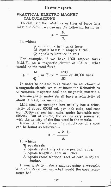
Electro-Magnets
PRACTICAL ELECTRO-MAGNETCALCULATIONS
To calculate the total flux or lines of force in amagnetic circuit we can use the following formulas:
M= -R
I n which :4) equals flux in lines of force.M equals MMF in ampere turns.7? equals reluctance in rels.
For example, if we have 1200 ampere turnsM.M.F., on a magnetic circuit of .03 rel, whatwould be the total flux?
M 1200st) = -, or Flux = - or 40,000 lines..03
In order to be able to calculate the reluctance ofa magnetic circuit, we must know the Reluctivitiesof common magnetic and non-magnetic materials.
Non-magnetic materials all have a reluctivity ofabout .313 rel, per inch cube.
Mild steel or wrought iron usually has a reluc-tivity of about .00018 rel, per inch cube, and castiron .00164 rel per inch cube, under favorable con-ditions. But of course, the values vary somewhatwith the density of the flux used in the metals.
Knowing these values, the reluctance of a corecan be found as follows:-
R1, X L
AIn which:
7? equals rels.v equals reluctivity of core per inch cube.L equals length of core in inches.A equals cross sectional area of core in square
inches.I f you wish to make a magnet using a wrought
iron core 2x2x8 inches, what would the core reluc-tance be?
147
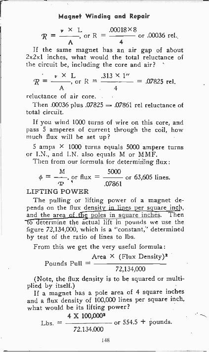
Magnet Winding and Repair
v x L .00018 x 8R - , or R or .00036 rel.
A 4
If the same magnet has an air gap of about2x2x1 inches, what would the total reluctance ofthe circuit be, including the core and air?
' v x L .313 X 1"R= , or R = -.07825re1.A 4
reluctance of air core.Then .00036 plus .07825 = .07861 rel reluctance of
total circuit.If you wind 1000 turns of wire on this core, and
pass 5 amperes of current through the coil, howmuch flux will be set up?
5 amps X 1000 turns equals 5000 ampere turnsor I.N., and I.N. also equals M or MMF.
Then from our formula for determining flux:M 5000
= , or flux = or 63,605 lines.ri? .07861
LIFTING POWERThe pulling or lifting power of a magnet de-
pends on the flux densit in lines_per square inch,and the area__ of t square inches. Thento determine the actual lift in pounds we use thefigure 72,134,000, which is a "constant," determinedby test of the ratio of lines to lbs.
From this we get the very useful formula:Area X (Flux Density)2
Pounds Pull -72,134,000
(Note, the flux density is to be squared or multi-plied by itself.)
If a magnet has a pole area of 4 square inchesand a flux density of 100,000 lines per square inch,what would be its lifting power?
4 X 100,0002Lbs. = or 554.5 + pounds.
72.134.000
148
Magnet Winding and Repair
So we find that a good magnet should lift over138 pounds per square inch of pole surface.
We can usually depend on a lift of over 100pounds per square inch even though the magnetis only working at a density of 90,000 lines persquare inch. This, of course, means the lift obtain-able when both poles of the magnet are actually ingood contact with the iron to be lifted.
You have now learned how to use the units Am-pere -turn, lines of force, and rel, to calculate fluxand pull of magnets by simplified formulas.
C. G. S. UNITSIt may be well to mention here another set of
units used in some cases instead of those abovementioned.
These are the Gilbert, Maxwell, and Oersted.The Gilbert is a unit of M.M.F., similar to the
ampere -turn, but one ampere -turn is larger, andequal to 1.257 Gilbert.
The Maxwell is a unit of flux, equal to oneline of force.
The Oersted is a unit of reluctance, and is thereluctar :e of 1 cubic centimeter of air or non-mag-netic material.
This second set of magnetic units are from theC.G.S. (Centimeter, gram, second) system of units,and can be used for practically the same purposeas the ampere -turn, line of force, and rel. Theymerely differ slightly in size, the same as the centi-meter and the inch are both units of measurement,only of different sizes.
The practical man will probably find the ampere-
turn, lines of force, and rel, much easier units touse, because they deal with square inches insteadof centimeters, and the ampere -turn is so easilyunderstood, as a unit of M.M.F. The other unitsare merely mentioned and explained here, so ifyou see or hear them used from time to time youwill understand their meaning.
149
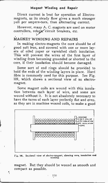
Magnet Winding and Repair
Direct current is best for operation of Electro-magnets, as its steady flow gives a much strongerpull per ampere -turn, than alternating current.
However, many A. C. magnets are used on motorcontrollers, relay;circuit breakers, etc.
MAGNET WINDING AND REPAIRSIn making electro-magnets the core should be of
good soft iron, and covered with one or more lay-ers of oiled paper or varnished cloth insulation.This will prevent the wires of the first layer ofwinding from becoming grounded or shorted to thecore, if their insulation should become damaged.
Some sort of end rings should be provided tohold the ends of the winding layers in place. Hardfibre is commonly used for this purpose. See Fig.101, which shows a sectional view of an electro-magnet.
Some magnet coils are wound with thin insula-tion between each layer of wire, and some arewound without it. It is not absolutely necessary tohave the turns of each layer perfectly flat and even,as they are in machine wound coils, to make a good
WINDINGSFIDER COLLARYfR INSELATION
ORE INSULATIONCORE
Fig. 101. Sectional view of electro-magnet, showing core, insulation andwinding.
magnet. But they should be wound as smooth andcompact as possible.
1.50
Magnet Winding and Repair
Magnet wires, with insulation of cotton, silk,enamel, or combinations of cotton -enamel or silk -enamel, are used for winding electro-magnets.Enamel is excellent electrical insulation, takes upthe least space in the coil, and carries heat to theoutside of coil very well. Therefore it is ideal formany forms of compact coils, of fine wires. But thecotton or silk covered wires are easier to handleand wind, as they stand the mechanical abusebetter.
When winding a magnet coil with very fine wireswhich are easily broken, it is well to splice a pieceof heavy flexible wire to the fine wire, for bothstarting and finishing leads of the coil. The pieceof heavier wire used in starting the coil shouldbe long enough to make several turns around thecore, to take all strain off the fine wire in case ofa pull on this end wire. Then wind the fine wireover the "lead in" wire, and when the coil is finishedattach another piece of heavy wire, and wrap itseveral times around the coil, to take any possiblestrain on this outer "lead" wire. Any splices madein the coil should be carefully done, well cleaned,and soldered, so they will not heat up, arc or burnopen, after the coil is finished and in service. Alayer of tape or varnished cloth should be put overthe outside of the coil to protect the wires fromdamage.
When repairing and rewinding magnet coils frommotors, controllers, relays, or any electrical equip-ment, be careful to replace the same number ofturns and same size of wire as you remove. Other-wise the repaired coil may overheat or not have theproper strength.
If the wire removed is coarse, the turns canusually be carefully counted. If it is very fine andperhaps many thousands of turns, it can be accur-ately weighed, and the same amount by weight,replaced.
The size of the wire used for the repair should
151
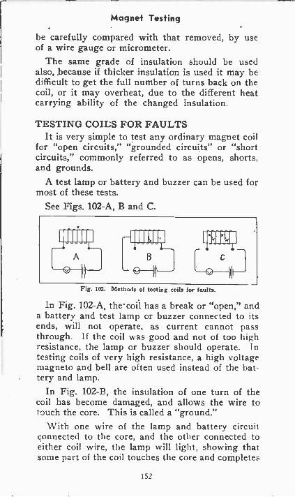
Magnet Testing
be carefully compared with that removed, by useof a wire gauge or micrometer.
The same grade of insulation should be usedalso, because if thicker insulation is used it may bedifficult to get the full number of turns back on thecoil, or it may overheat, due to the different heatcarrying ability of the changed insulation.
TESTING COILS FOR FAULTSIt is very simple to test any ordinary magnet coil
for "open circuits," "grounded circuits" or "shortcircuits," commonly referred to as opens, shorts,and grounds.
A test lamp or battery and buzzer can be used formost of these tests.
See Figs. 102-A, B and C.
Fig. 102. Methods of testing coils for faults.
In Fig. 102-A, thecoil has a break or "open," anda battery and test lamp or buzzer connected to itsends, will not operate, as current cannot passthrough. lithe coil was good and not of too highresistance, the lamp or buzzer should operate. Intesting coils of very high resistance, a high voltagemagneto and bell are often used instead of the bat-tery and lamp.
In Fig. 102-B, the insulation of one turn of thecoil has become damaged, and allows the wire totouch the core. This is called a "ground."
With one wire of the lamp and battery circuitconnected to the core, and the other connected toeither coil wire, the lamp will light, showing thatsome part of the coil touches the core and completes
lit
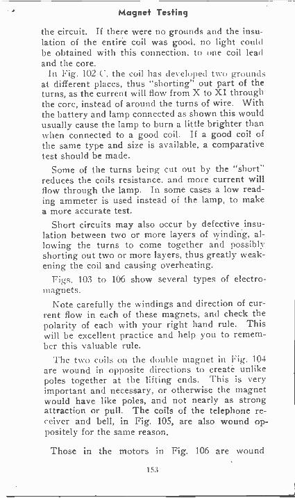
Magnet Testing
the circuit. If there were no grounds and the insu-lation of the entire coil was good. no light couldbe obtained with this connection, to one coil leadand the core.
In Fig. 102-C, the coil has developed two groundsat different places, thus "shorting" out part of theturns, as the current will flow from X to X1 throughthe core, instead of around the turns of wire. Withthe battery and lamp connected as shown this wouldusually cause the lamp to burn a little brighter thanwhen connected to a good coil. If a good coil ofthe same type and size is available, a comparativetest should be made.
Some of the turns being cut out by the "short"reduces the coils resistance, and more current willflow through the lamp. In some cases a low read-ing ammeter is used instead of the lamp, to makea more accurate test.
Short circuits may also occur by defective insu-lation between two or more layers of winding, al-lowing the turns to come together and possiblyshorting out two or more layers, thus greatly weak-ening the coil and causing overheating.
Figs. 103 to 106 show several types of electro-magnets.
Note carefully the windings and direction of cur-rent flow in each of these magnets, and check thepolarity of each with your right hand rule. Thiswill be excellent practice and help you to remem-ber this valuable rule.
The two coils on the double magnet in Fig. 104are wound in opposite directions to create unlikepoles together at the lifting ends. This is veryimportant and necessary, or otherwise the magnetwould have like poles, and not nearly as strongattraction or pull. The coils of the telephone re-ceiver and bell, in Fig. 105, are also wound op-positely for the same reason.
Those in the motors in Fig. 106 are wound
153
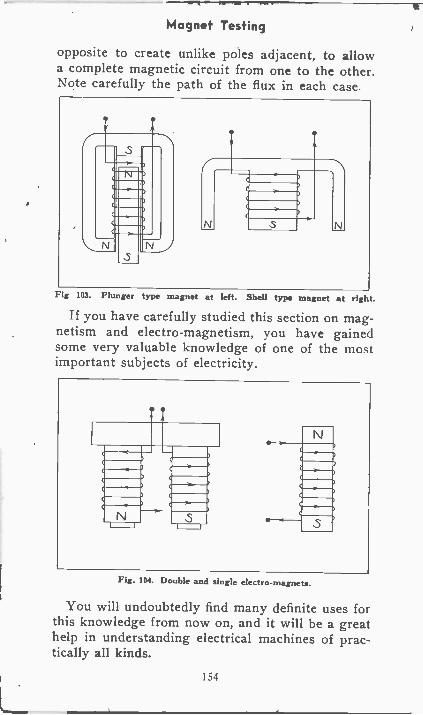
Magnet Testing
opposite to create unlike poles adjacent, to allowa complete magnetic circuit from one to the other.Note carefully the path of the flux in each case
rFig 103. Plunger type magnet at left. Shell type magnet at right.
If you have carefully studied this section on mag-netism and electro-magnetism, you have gainedsome very valuable knowledge of one of the mostimportant subjects of electricity.
Fig. 104. Double and single electro-magnets.
You will undoubtedly find many definite uses forthis knowledge from now on, and it will be a greathelp in understanding electrical machines of prac-tically all kinds.
154
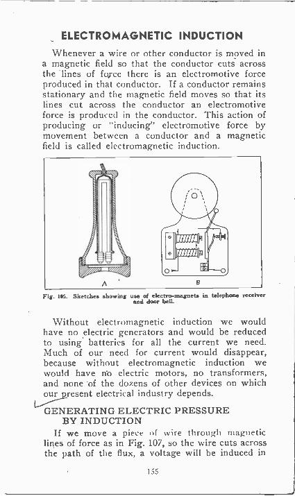
ELECTROMAGNETIC INDUCTION
Whenever a wire or other conductor is moved ina magnetic field so that the conductor cuts acrossthe lines of force there is an electromotive forceproduced in that conductor. If a conductor remainsstationary and the magnetic field moves so that itslines cut across the conductor an electromotiveforce is produced in the conductor. This action ofproducing or "inducing" electromotive force bymovement between a conductor and a magneticfield is called electromagnetic induction.
Fig. 105. Sketches showing use of electro-magnets in telephone receiverand door bell.
Without electromagnetic induction we wouldhave no electric generators and would be reducedto using batteries for all the current we need.Much of our need for current would disappear,because without electromagnetic induction wewould have rio electric motors, no transformers,and none of the dozens of other devices on whichour present electrical industry depends.
GENERATING ELECTRIC PRESSUREBY INDUCTION
If we move a piece of wire through magneticlines of force as in Fig. 107, so the wire cuts acrossthe path of the flux, a voltage will be induced in
155
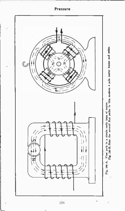
Fig.
106
-A.
Flux
pat
h in
a s
impl
e ea
rly
type
of
mot
or.
Fig.
106
-B. N
ote
the
seve
ral f
lux
path
s in
this
mod
ern
4 po
le m
otor
fra
me
and
pole
s.
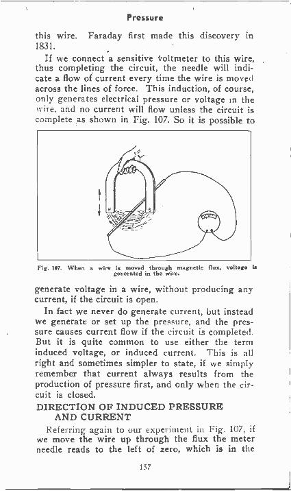
Pressure
this wire. Faraday first made this discovery in1831.
If we connect a sensitive voltmeter to this wire,thus completing the circuit, the needle will indi-cate a flow of current every time the wire is movedacross the lines of force. This induction, of course,only generates electrical pressure or voltage in thewire, and no current will flow unless the circuit iscomplete as shown in Fig. 107. So it is possible to
Fig. 107. When a wire is moved through magnetic flux, voltage isgenerated in the wire.
generate voltage in a wire, without producing anycurrent, if the circuit is open.
In fact we never do generate current, but insteadwe generate or set up the pressure, and the pres-sure causes current flow if the circuit is completed.But it is quite common to use either the terminduced voltage, or induced current. This is allright and sometimes simpler to state, if we simplyremember that current always results from theproduction of pressure first, and only when the cir-cuit is closed.DIRECTION OF INDUCED PRESSURE
AND CURRENTReferring again to our experiment in Fig. 107, if
we move the wire up through the flux the meterneedle reads to the left of zero, which is in the
157
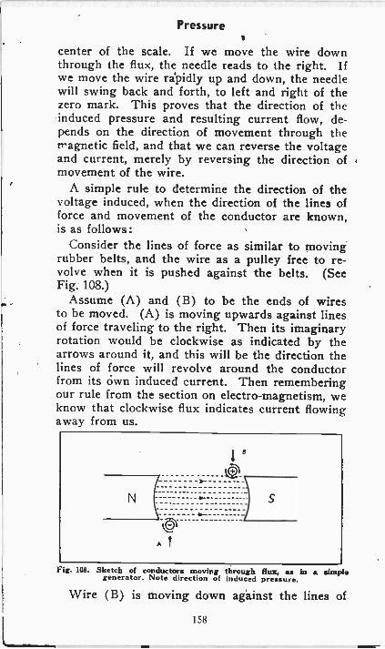
Pressure
center of the scale. If we move the wire downthrough the flux, the needle reads to the right. Ifwe move the wire rapidly up and down, the needlewill swing back and forth, to left and right of thezero mark. This proves that the direction of theinduced pressure and resulting current flow, de-pends on the direction of movement through themagnetic field, and that we can reverse the voltageand current, merely by reversing the direction ofmovement of the wire.
A simple rule to determine the direction of thevoltage induced, when the direction of the lines offorce and movement of the conductor are known,is as follows:
Consider the lines of force as similar to movingrubber belts, and the wire as a pulley free to re-volve when it is pushed against the belts. (SeeFig. 108.)
Assume (A) and (B) to be the ends of wiresto be moved. (A) is moving upwards against linesof force traveling to the right. Then its imaginaryrotation would be clockwise as indicated by thearrows around it, and this will be the direction thelines of force will revolve around the conductorfrom its own induced current. Then rememberingour rule from the section on electro-magnetism, weknow that clockwise flux indicates current flowingaway from us.
N
1°lc)
S
Al
Fig. 108. Sketch of conductors moving through flux, as in a simplegenerator. Note direction of induced pressure.
Wire (B) is moving down against the lines of
158
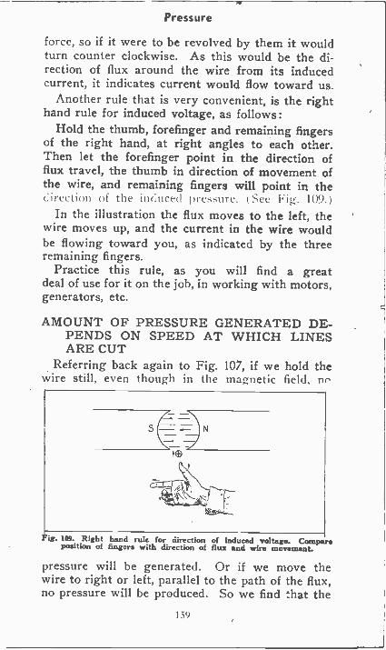
Pressure
force, so if it were to be revolved by them it wouldturn counter clockwise. As this would be the di-rection of flux around the wire from its inducedcurrent, it indicates current would flow toward us.
Another rule that is very convenient, is the righthand rule for induced voltage, as follows:
Hold the thumb, forefinger and remaining fingersof the right hand, at right angles to each other.Then let the forefinger point in the direction offlux travel, the thumb in direction of movement ofthe wire, and remaining fingers will point in thedirection H! the in(tice(1 pres-ore.See Fig 104). )
In the illustration the flux moves to the left, thewire moves up, and the current in the wire wouldbe flowing toward you, as indicated by the threeremaining fingers.
Practice this rule, as you will find a greatdeal of use for it on the job, in working with motors,generators, etc.
AMOUNT OF PRESSURE GENERATED DE-PENDS ON SPEED AT WHICH LINESARE CUT
Referring back again to Fig. 107, if we hold thewire still, even though in the magnetic field. no
Fig. 109. Right hand rule for direction of Induced voltage. Compareposition of fingers with direction of flux and wire movement.
pressure will be generated. Or if we move thewire to right or left, parallel to the path of the flux,no pressure will be produced. So we find that the
159
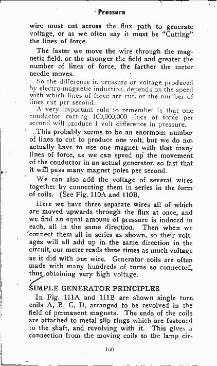
Pressure
wire must cut across the flux path to generatevoltage, or as we often say it must be "Cutting"the lines of force.
The faster we move the wire through the mag-netic field, or the stronger the field and greater thenumber of lines of force, the farther the meterneedle moves.
So the difference in pressure or voltage producedby electro-magnetic induction, depends on the speedwith which lines of force are cut, or the number oflines cut per second.
A very important rule to remember is that oneconductor cutting 100,000,000 lines of force persecond will produce 1 volt difference in pressure.
This probably seems to be an enormous numberof lines to cut to produce one volt, but we do notactually have to use one magnet with that manylines of force, as we can speed up the movementof the conductor in an actual generator, so fast thatit will pass many magnet poles per second.
We can also add the voltage of several wirestogether by connecting them in series in the formof coils. (See Fig. 110A and 110B.
Here we have three separate wires all of whichare moved upwards through the flux at once, andwe find an equal amount of pressure is induced ineach, all in the same direction. Then when weconnect them all in series as shown, so their volt-ages will all add up in the same direction in thecircuit, our meter reads three times as much voltageas it did with one wire. Generator coils are oftenmade with many hundreds of turns so connected,thus obtaining very high voltage.
SIMPLE GENERATOR PRINCIPLESIn Fig. 111A and 111B are shown single turn
coils A, B, C, D, arranged to be revolved in thefield of permanent magnets. The ends of the coilsare attached to metal slip rings which are fastenedto the shaft, and revolving with it. This gives aconnection from the moving coils to the lamp cir-
160
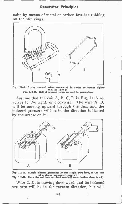
Generator Principles
cuits by means of metal or carbon brushes rubbingon the slip rings.
Fig. 110-A. Using several wires connected in series to obtain higherinduced voltage.
Fig. 110-B. Coil of several tutus, as used in generators.
Assume that the coil A, B, C, D in Fig. 111A re-volves to the right, or clockwise. The wire A. B,will be moving upward through the flux, and theinduced pressure will be in the direction indicatedby the arrow on it.
Fig. 111-A. Simple electric generator of one single wire loop, in the fluxof a strong permanent mnet.
Fig. 111-B. Here the colt has revolved one-hallturn farther than In (A).
Wire C, D, is moving downward, and its inducedpressure will be in the reverse direction, but will
161
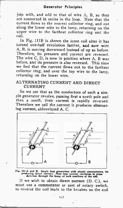
Generator Principles
join with, and add to that of wire A, B, as theyare connected in series in the loop. Note that thecurrent flows to the nearest collector ring, and outalong the lower wire to the lamp, returning on theupper wire to the farthest collector ring and thecoil.
In Fig. 111B is shown the same coil after it hasturned one-half revolution farther, and now wireA, B, is moving downward instead of up as before.Therefore, its pressure and current are reversed.The wire C, D, is now in position where A, B wasbefore, and its pressure is also reversed. This timewe find that the current flows out to the farthestcollector ring, and over the top wire to the lamp,returning on the lower wire.
ALTERNATING CURRENT AND DIRECTCURRENT
So we see that as the conductors of such a sim-ple generator revolve, passing first a north pole andthen a south, their current is rapidly reversed.
Therefore we call the current it produces alternat-ing current, abbreviated A. C.
Fig. I12 -A and B. Single loop generators with simple commutators, forproducing direct current. Note how current continues In same
direction through the lamp, at both positions of the coll.
If we wish to obtain direct current (D. C.), wemust use a commutator or sort of rotary switch,to reverse the coil leads to the brushes as the coil
162
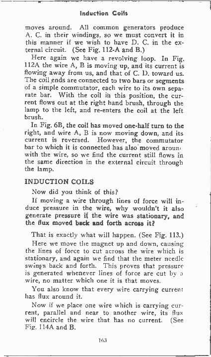
Induction Coils
moves around. All common generators produceA. C. in their windings, so we must convert it inthis manner if we wish to have D. C. in the ex-ternal circuit. (See Fig. 112-A and B.)
Here again we have a revolving loop. In Fig.112A the wire A, B is moving up, and its current isflowing away from us, and that of C. D. toward us.The coil ends are connected to two bars or segmentsof a simple commutator, each wire to its own sepa-rate bar. With the coil in this position, the cur-rent flows out at the right hand brush, through thelamp to the left, and re-enters the coil at the leftbrush.
In Fig. 6B, the coil has moved one-half turn to theright, and wire A, B is now moving down, and itscurrent is reversed. However, the commutatorbar to which it is connected has also moved arounfwith the wire, so we find the current still flows inthe same direction in the external circuit throughthe lamp.
INDUCTION COILSNow did you think of this?If moving a wire through lines of force will in-
duce pressure in the wire, why wouldn't it alsogenerate pressure if the wire was stationary, andthe flux moved back sad forth across it?
That is exactly what will happen. (See Fig. 113.)Here we move the magnet up and down, causing
the lines of force to cut across the wire which isstationary, and again we find that the meter needleswing s back and forth. This proves that pressureis generated whenever lines of force are cut by awire, no matter which one it is that moves.
You also know that every wire carrying currenthas flux around it.
Now if we place one wire which is carrying cur-rent, parallel and near to another wire, its fluxwill encircle the wire that has no current. (SeeFig. 114A and B.
163
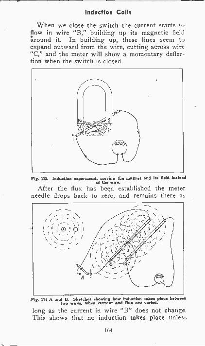
Induction Coils
When we close the switch the current starts toflow in wire "B," building up its magnetic fieldaround it. In building up, these lines seem toexpand outward from the wire, cutting across wire"C," and the meter will show a momentary deflec-tion when the switch is closed.
Fig. 113. Induction experiment, moving the magnet and its field insteadof the wire.
After the flux has been established the meterneedle drops back to zero, and remains there as
Fig. 114-A and B. Sketches showing how induction takes place betweentwo wires, when current and flux are varied.
long as the current in wire "B" does not change.This shows that no induction takes place unless
164
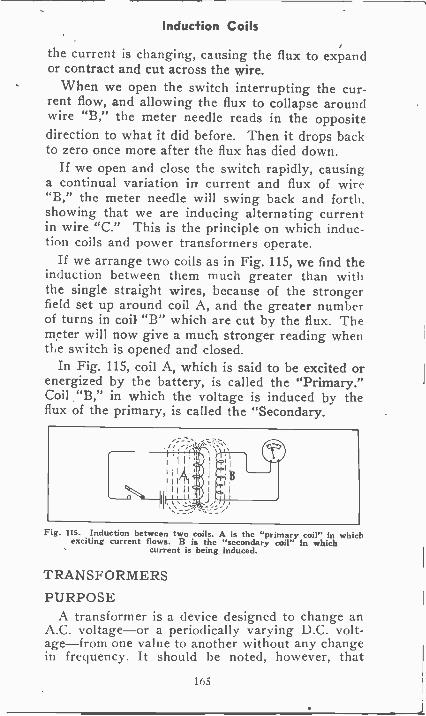
Induction Coils
the current is changing, causing the flux to expandor contract and cut across the wire.
When we open the switch interrupting the cur-rent flow, and allowing the flux to collapse aroundwire "B," the meter needle reads in the oppositedirection to what it did before. Then it drops backto zero once more after the flux has died down.
If we open and close the switch rapidly, causinga continual variation in current and flux of wire"B," the meter needle will swing back and forth,showing that we are inducing alternating currentin wire "C." This is the principle on which induc-tion coils and power transformers operate.
If we arrange two coils as in Fig. 115, we find theinduction between them much greater than withthe single straight wires, because of the strongerfield set up around coil A, and the greater numberof turns in coil "B" which are cut by the flux. Themeter will now give a much stronger reading whenthe switch is opened and closed.
In Fig. 115, coil A, which is said to be excited orenergized by the battery, is called the "Primary."Coil "B," in which the voltage is induced by theflux of the primary, is called the "Secondary.
Fig. 115. Induction between two coils. A is the "primary coil" in whichexciting current flows. B is the "secondary coil" in which
current is being induced.
TRANSFORMERS
PURPOSEA transformer is a device designed to change an
A.C. voltage-or a periodically varying D.C. volt-age-from one value to another without any changein frequency. It should be noted, however, that
165
Transformers
while the input to a transformer may be pulsatingD.C., the output will always be A.C.CONSTRUCTION
The ordinary transformer consists of a primarywinding - connected to the source of energy -alaminated iron core, and one or more secondarywindings. Theoretically, any winding may be usedas the primary, provided the proper voltage andfrequency be applied to it. The laminated iron coreserves as an efficient means of magnetically couplingtogether the primary and secondary windings.ACTION
A periodically varying voltage applied to the pri-mary winding produces a varying current that inturn develops a varying flux in the iron core. Thisvarying flux cuts all windings, inducing in ,each ofthem a voltage proportional to the number of turns.TURNS RATIO
The ratio of the primary voltage to any secon-dary voltage is practically equal to the ratio of theprimary turns to the secondary turns as indicatedby the formula:
Primary turns Primary voltageSecondary turns Secondary voltage
ACTION UNDER LOADThe voltage induced in the primary winding by
the growing and dying core flux is practically equalto the applied voltage; moreover, this induced volt-age directly opposes the appli61 voltage ; therefore,the current drawn from the supply is small.
When a secondary circuit is completed, currentcirculates around the iron core in the opposite direc-tion to the primary current, reducing the core fluxand the counter voltage of the primary. This actioncauses the current in the primary to vary in accord-ance with the secondary load. It is through thisaction that the transformer automatically adjustsitself to changes in secondary load.
Two coils or windings on a single magnetic coreform a transformer. With a transformer we maytake a large alternating current at low voltage and
166
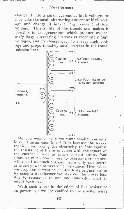
Transformers
change it into a small current at high voltage, ormay take the small alternating current at high volt-age and change it into a large current at lowvoltage. This ability of the transformer makes itpossible to use generators which produce moder-ately large alternating currents at moderately highvoltages, and to change over to a very high volt-age and proportionately small current in the trans-mission lines. 5
110 VOLTPRIMARY
CENTERTAP.
CENTERTAP.
6
6 3 VOLT FILAMENTWINDING
5 0 VOLT RECTIFIERFILAMENT WINDING.
HIGH VOLTAGEWINDING.
Do you wonder why we want smaller currentsin our transmission lines? It is because the powerrequired for forcing the electricity to flow againstthe resistance of the lines varies with the square ofthe current. Twice as much current means fourtimes as much power just to overcome resistance,while half as much current means only one-fourthas much power to overcome resistance. Then whenwe drop the current to one -tenth its original valueby using a transformer we have cut the power lossdue to resistance to one one -hundredth what itmight have been.
With such a cut in the effect of line resistanceon power loss we are enabled to use smaller wires
167
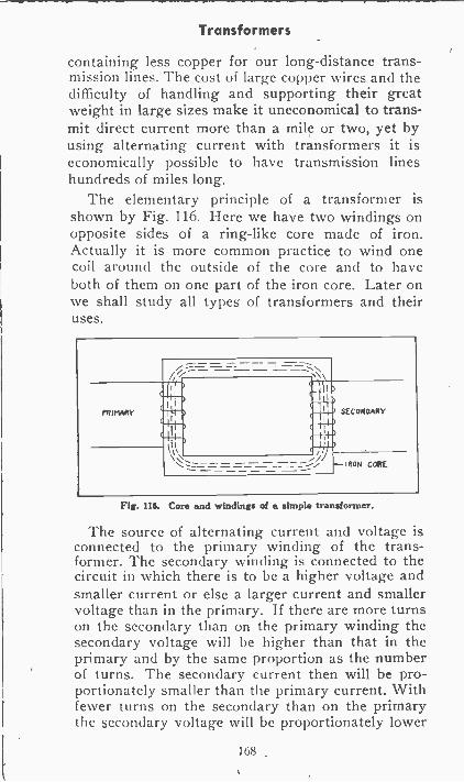
Transformers
containing less copper for our long-distance trans-mission lines. The cost of large copper wires and thedifficulty of handling and supporting their greatweight in large sizes make it uneconomical to trans-mit direct current more than a mile or two, yet byusing alternating current with transformers it iseconomically possible to have transmission lineshundreds of miles long.
The elementary principle of a transformer isshown by Fig. 116. Here we have two windings onopposite sides of a ring -like core made of iron.Actually it is more common practice to wind onecoil around the outside of the core and to haveboth of them on one part of the iron core. Later onwe shall study all types' of transformers and theiruses.
PRIMARY
ma am,MI' MI.M.,III' lamg"11111. SECONDARY
IRON CONE
Fig. Ili. Cars and windings of a simple transformer.
The source of alternating current and voltage isconnected to the primary winding of the trans-former. The secondary winding is connected to thecircuit in which there is to be a higher voltage andsmaller current or else a larger current and smallervoltage than in the primary. If there are more turnson the secondary than on the primary winding thesecondary voltage will be higher than that in theprimary and by the same proportion as the numberof turns. The secondary current then will be pro-portionately smaller than the primary current. Withfewer turns on the secondary than on the primarythe secondary voltage will be proportionately lower
168
Transformers
than that in the primary, and the secondary currentwill he that much larger. Alternating curr,:nt iscontinually changing, continually increasing anddecreasing in value. Every change of alternatingcurrent in the primary winding of the transformerproduces a similar change of flux in the core. Everychange of flux in the core, and every correspondingmovement of magnetic field around the core, pro-duces a similarly changing movement of magneticfield around the core, produces a similarly changingelectromotive force in the secondary winding andcauses an alternating current to flow in the circuitwhich is connected to the secondary.
In discussing the action of the transformer wehave mentioned electric power and loss of power.As you well realize, the production, transmissionand use of power represent much of the practiceof electricity. In the following section we shall talkabout power, what it really means, and how it ismeasured.
STATIC ELECTRICITYCHARGES OF ELECTRICITY
Imagine that you have a sheet of mica, glass, hardrubber or some other insulating material and thaton each side of the insulating material are metalplates. The metal plates are insulated from eachother by the material between them. If you wereto connect the metal plates to the two terminalsof a battery or other source of d -c potential therewould be a momentary flow of current from thepositive side of the battery to one plate and anequal flow of current from the other plate to thenegative side of the battery. The flow of currentwould exist for only an instant, then would stop.No current could continue to flow because there isinsulation between the metal plates.
If the battery were disconnected from the metalplates and then reconnected to them in the samemanner as before there would be no momentary
169
Static Electricity
flow of current provided the plates had remainedcompletely insulated from all electrical conductorswhile the battery was disconnected. It is evidentthat the first connection of the battery producedsome change in the insulating material betweenthe plates which enabled them to oppose flow ofcurrent during the second test.
When first studying electricity we learned thatall substances consist of atoms which containelectrons, and that electrons are particles of nega-tive electricity. When a potential difference isapplied to conductors separated by insulation, asto the metal plates just discussed, the potentialdifference causes negative electrons to flow fromone side of the potential source to one of the con-ductors or metal plates. These negative electronspass to the side of the insulator in contact with theplate, and that side of the insulator becomes morenegative. An equal quantity of electrons leaves theopposite side of the insulator and passes throughthe other metal plate to the other side of the poten-tial source. This loss of negative electrons leavesthis side of the insulator more positive than before.
When an insulating material is used in the man-ner described it is called a dielectric. The side ofthe dielectric connected to the positive terminalof the battery acquires a positive charge of elec-tricity-meaning that it loses some negative elec-trons and becomes more positive. The side of thedielectric connected to the negative terminal of thesource becomes negatively charged, meaning thatit has more than the normal number of electrons.Since the dielectric is an insulator, through whichelectricity or electrons cannot flow, the unbalancedcondition will persist on the surfaces of the dielectricwhen the battery or other source is disconnected,and would persist were the dielectric removed frombetween the plates so long as the dielectric comesin contact with no conductors.
170
Static Electricity
An electric potential, or a difference of potential,means simply that there are more electrons at oneplace than at another, or that one place has morethan its normal number of electrons, or that anotherhas fewer than its normal number.
Any difference of potential is measured in volts.Connecting the battery to the plates and the dielec-tric produced a difference of potential on oppositesides of the dielectric, equal to the difference ofpotential furnished by the battery. Consequently,when you connect the battery to the plates a secondtime the battery potential is opposed by a potentialequally great on the dielectric. The positive ter-minal of the battery is connected to the side of thedielectric having a positive charge and the negativeterminal of. the battery to the side having a negativecharge. The potential difference of these charges isequal to that of the battery, so no current flows.
CAPACITANCE AND CAPACITORSConductors separated by insulation or a dielec-
tric, and having a difference of potential, have theability to produce electric charges on the dielectric.This ability to receive and hold electric charges iscalled capacitance or may be called electrostaticcapacity. A device which contains conductive platesand insulating dielectric arranged especially for re-ceiving electric charges, is called a capacitor or anelectrostatic condenser.
The capacitance of a capacitor is measured in ac-cordance with the quantity of electricity (electrons)which may be added to one side and taken off theother side of the dielectric. If a potential differenceof one volt causes one coulomb of electricity to flowinto a capacitor the capacitance is one farad. If wemade a capacitor with mica only as thick as thepaper in this page, and used a single square sheet,.our capacitor would have to measure more than amile along each side to haft a capacitance of onefarad. A unit so large as the farad is impractical for
171
Static Electricity
ordinary capacitors, so we use the microfarad whichis equal to one one -millionth of a farad.
The capacitance varies with the kind of dielectric,and the effect of the kind of dielectric on capacitanceis called the dielectric constant of the material. Thedielectric constant of air is 1.0, while that of waxedpaper, as one example, is from 2.5 to 4.0. Thismeans that a capacitor with waxed paper dielectricwill have a capacitance 2.5 to 4.0 times as great asan otherwise similar one having air for -its dielectric.Dielectric constants of most insulating materialsrange from 1.5 to 8.0.
With a given knid of dielectric, capacitance be-comes less in direct proportion as the dielectric ismade thicker, and becomes more in direct propor-tion as the area of dielectric in contact with theplates is made greater. Many capacitors which areto withstand voltages of only a few hundred havedielectrics of several sheets of thin waxed paper.For high voltages the dielectric usually is sheetsof mica.
If a capacitor is connected in a direct -current cir-cuit there will be a momentary flow of current asthe capacitor takes its charge, then the current willstop because the dielectric is an insulator.
If a capacitor is connected in an alternating-current circuit the flow in amperes will be reducedbut some current will continue to flow. The greaterthe capacitance of the capacitor the larger will bethe remaining current. This rather peculiar actionis due to the fact that alternating current merelysurges back and forth in a circuit, moving first onedirection and then the other. The alternating cur-rent may flow in one direction until it charges thecapacitor in that direction, then may flow in theopposite direction as the capacitor discharges and isrecharged in the opposite direction or oppositepolarity.
172
Static Electricity
ELECTROSTATIC FIELDSJust as there is a magnetic field and magnetic
lines of force around a magnet so there is an elec-trostatic field and electrostatic lines of force aroundan insulating material or dielectric material whichis electrically charged. The electrostatic field maybe represented by lines between electrostatic polesjust as the magnetic field is represented by linesbetween magnetic poles. Electrostatic lines issuefrom the positive electrostatic pole and return tothe negative electrostatic pole.
The positively charged end of a dielectric may becalled its positive pole, and the negatively chargedend its negative pole. Unlike electrostatic poles, onepositive and the other negative, attract each otherjust as do unlike magnetic poles. Like electrostaticpoles, or like charges, repel each other-which againis similar to the behavior of magnetic poles.
The greater the dielectric constant of a substancethe more easily it carries electrostatic lines of force.Consequently, when a material of high dielectricconstant is placed within an electrostatic field thismaterial tends to draw into it some of the electro-static lines which otherwise would travel throughthe surrounding air, which is of lower dielectricconstant.
It is important to understand that the potentialdifference between opposite sides of a charged die-lectric may be very high and yet the quantity ofelectricity which will flow to and from the dielectricmay be very small. As an example, many of thecapacitors used in radio have capacitances of onlya fraction of a microfarad, which means they witcharge with only a little electricity and then willdischarge a similarly small quantity. But thesecapacitors may be charged to potentials of hun-dreds of volts, or even thousands in transmittingoutfits. Many a radio man has received a stingingshock from the high potential discharge from a
173
Static Electricity
capacitor of fairly small physical size.Electricity which exists as an excess or as a de-
ficiency on charged bodies such as dielectrics is atrest or remains stationary except while the bodyis being charged or discharged. This electricitywhich is stationary is called static electricity, andwhen talking about its effects we use the wordelectrostatic to distinguish them from effects ofmoving electricity, which is the electric current.
ELECTRIC CHARGES PRODUCED BYFRICTIONIf you rub a stick of sealing wax with wool, silk
or cotton cloth you actually rub some electrons offthe cloth and onto the wax. The sealing wax thenhas extra negative electrons, so is negativelycharged. The cloth has lost negative electrons, soremains positively charged. Now there are electro-static fields around both the wax and the cloth, andeither will attract small bits of paper, thread andother insulating or dielectric materials-just aseither pole of a magnet will attract pieces of ironand steel. This experiment shows that electriccharges may result from friction when two insulat-ing materials are rubbed together. Such frictionalcharges of static electricity are harmful more oftenthan useful.METHODS OF STATIC CONTROL AND
PROTECTIONNow that we have an idea of the general nature
of static electricity it will be well to consider someof the forms in which it is often encountered inevery day life outside the laboratory. Alsosome of the methods of controlling, or protectingagainst it, because in some of the forms in whichit is produced by nature, and in our industries, itcan be very harmful if not guarded against.
For example, one of the most common occur -
174
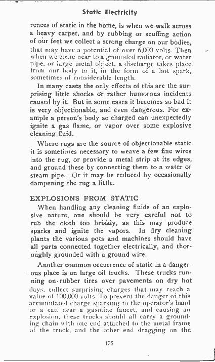
Static Electricity
rences of static in the home, is when we walk acrossa heavy carpet, and by rubbing or scuffing actionof our feet we collect a strong charge on our bodies,that may have a potential of over 6,000 volts. Thenwhen we come near to a grounded radiator, or waterpipe, or large metal object, a discharge takes placefrom our body to it, in the form of a hot spark,sometimes of considerable length.
In many cases the only effects of this are the sur-prising little shocks or rather humorous incidentscaused by it. But in some cases it becomes so bad itis very objectionable, and even dangerous. For ex-ample a person's body so charged can unexpectedlyignite a gas flame, or vapor over some explosivecleaning fluid.
Where rugs are the source of objectionable staticit is sometimes necessary to weave a few fine wiresinto the rug, or provide a metal strip at its edges,and ground these by connecting them to a water orsteam pipe. Or it may be reduced by occasionallydampening the rug a little.
EXPLOSIONS FROM STATICWhen handling any cleaning fluids of an explo-
sive nature, one should be very careful not torub the cloth too briskly, as this may producesparks and ignite the vapors. In dry cleaningplants the various pots and machines should haveall parts connected together electrically, and thor-oughly grounded with a ground wire.
Another common occurrence of static in a danger-ous place is on large oil trucks. These trucks run-ning on rubber tires over pavements on dry hot(lays, collect surprising- charges that may reach avalue of 100,000 volts. To prevent the danger of thisaccumulated charge sparking to the operator's handor a can near a gasoline faucet, and causing anexplosion, these trucks should all carry a ground-ing chain with one end attached to the metal frameof the truck, and the other end dragging on the
175
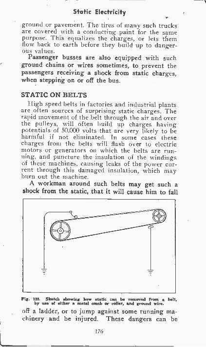
Static Electricity
ground or pavement. The tires of many such trucksare covered with a conducting paint for the samepurpose. This equalizes the charges, or lets themflow back to earth before they build up to danger-ous values.
Passenger busses are also equipped with suchground chains or wires sometimes, to prevent thepassengers receiving a shock from static charges,when stepping on or off the bus.
STATIC ON BELTSHigh speed belts in factories and industrial plants
are often sources of surprising static charges. Therapid movement of the belt through the air and overthe pulleys, will often build up charges havingpotentials of 50,000 volts that are very likely to beharmful if not eliminated. In some cases thesecharges from the belts will flash over to electricmotors or generators on which the belts are run-ning, and puncture the insulation of the windingsof these machines, causing leaks of the power cur-rent through this damaged insulation, which mayburn out the machine.
A workman around such belts may get such ashock from the static, that it will cause him to fall
Fig. 120. Sketch showing how static can be removed from a belt,by use of either a metal comb or roller, and ground wire.
oft a ladder, or to jump against some running ma-chinery and be injured. These dangers can be
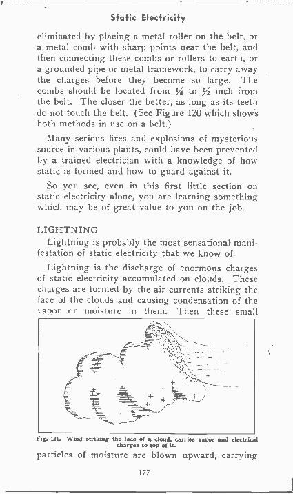
Static Electricity
eliminated by placing a metal roller on the belt, ora metal comb with sharp points near the belt, andthen connecting these combs or rollers to earth, ora grounded pipe or metal framework, to carry awaythe charges before they become so large. Thecombs should be located from IA to Y2 inch fromthe belt. The closer the better, as long as its teethdo not touch the belt. (See Figure 120 which showsboth methods in use on a belt.)
Many serious fires and explosions of mysterioussource in various plants, could have been preventedby a trained electrician with a knowledge of howstatic is formed and how to guard against it.
So you see, even in this first little section onstatic electricity alone, you are learning somethingwhich may be of great value to you on the job.
LIGHTNINGLightning is probably the most sensational mani-
festation of static electricity that we know of.Lightning is the discharge of enormous charges
of static electricity accumulated on clouds. Thesecharges are formed by the air currents striking theface of the clouds and causing condensation of thek apor or moisture in them. Then these small
Fig. 121. Wind striking the face of a cloud, carries vapor and electricalcharges to top of it.
particles of moisture are blown upward, carrying
177
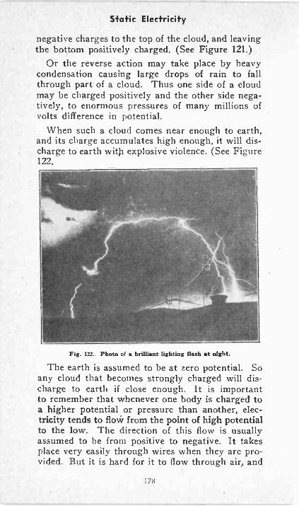
Static Electricity
negative charges to the top of the cloud, and leavingthe bottom positively charged. (See Figure 121.)
Or the reverse action may take place by heavycondensation causing large drops of rain to fallthrough part of a cloud. Thus one side of a cloudmay be charged positively and the other side nega-tively, to enormous pressures of many millions ofvolts difference in potential.
When such a cloud comes near enough to earth,and its charge accumulates high enough, it will dis-charge to earth with explosive violence. (See Figure122.
Fig. 122. Photo of a brilliant lighting Raab at night.
The earth is assumed to be at zero potential. Soany cloud that becomes strongly charged will dis-charge to earth if close enough. It is importantto remember that whenever one body is charged toa higher potential or pressure than another, elec-tricity tends to flow from the point of high potentialto the low. The direction of this flow is usuallyassumed to be from positive to negative. It takesplace very easily through wires when they are pro-vided. But it is hard for it to flow through air, and
178
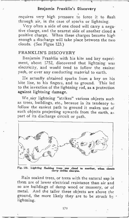
Benjamin Franklin's Discovery
requires very high pressure to force it to flashthrough air, in the case of sparks or lightning.
Very often a side of one cloud will carry a nega-tive charge, and the nearest side of another cloud apositive charge. When these charges become highenough a discharge will take place between the twoclouds. (See Figue 123.)
FRANKLIN'S DISCOVERYBenjamin Franklin with his kite and key experi-
ment, about 1752, discovered that lightning waselectricity, and would tend to follow the easiestpath, or over any conducting material to earth.
He actually obtained sparks from a key on hiskite line, to his fingers, and to ground. This ledto the invention of the lightning rod, as a protectionagainst lightning damage.
We say lightning "strikes" various objects suchas trees, buildings, etc., because in its tendency tofollow to ground it makes use ofsuch objects projecting upwards from the earth, aspart of its discharge circuit or path.
Fig. In. Lighting flashing from one cloud to another. when cloudscarry unlike charges.
Rain soaked trees, or trees with the natural sap inthem are of lower electrical resistance than air andso are buildings of damp wood or masonry, or ofmetal. And the taller these objects are above theground, the more likely they are to be struck bylightning.
179
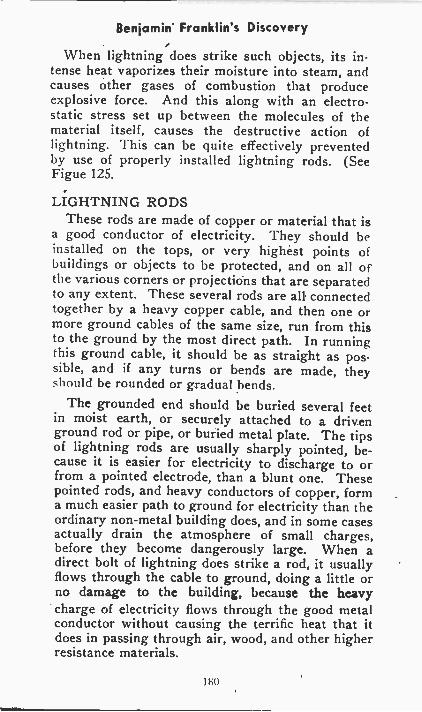
Benjamin Franklin's Discovery
When lightning does strike such objects, its in-tense heat vaporizes their moisture into steam, andcauses other gases of combustion that produceexplosive force. And this along with an electro-static stress set up between the molecules of thematerial itself, causes the destructive action oflightning. This can be quite effectively preventedby use of properly installed lightning rods. (SeeFigue 125.
LIGHTNING RODSThese rods are made of copper or material that is
a good conductor of electricity. They should beinstalled on the tops, or very highest points ofbuildings or objects to be protected, and on all ofthe various corners or projections that are separatedto any extent. These several rods are all connectedtogether by a heavy copper cable, and then one ormore ground cables of the same size, run from thisto the ground by the most direct path. In runningthis ground cable, it should be as straight as pos-sible, and if any turns or bends are made, theyshould be rounded or gradual bends.
The grounded end should be buried several feetin moist earth, or securely attached to a drivenground rod or pipe, or buried metal plate. The tipsof lightning rods are usually sharply pointed, be-cause it is easier for electricity to discharge to orfrom a pointed electrode, than a blunt one. Thesepointed rods, and heavy conductors of copper, forma much easier path to ground for electricity than theordinary non-metal building does, and in some casesactually drain the atmosphere of small charges,before they become dangerously large. When adirect bolt of lightning does strike a rod, it usuallyflows through the cable to ground, doing a little orno damage to the building, because the heavycharge of electricity flows through the good metalconductor without causing the terrific heat that itdoes in passing through air, wood, and other higherresistance materials.
180
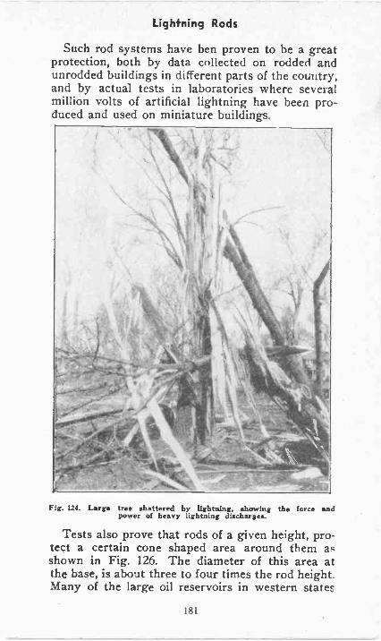
Lightning Rods
Such rod systems have ben proven to be a greatprotection, both by data collected on rodded andunrodded buildings in different parts of the country,and by actual tests in laboratories where severalmillion volts of artificial lightning have been pro-duced and used on miniature buildings.
Fig. 124. Large tree shattered by lightning, showing the force andpower of heavy lightning discharges.
Tests also prove that rods of a given height, pro-tect a certain cone shaped area around them asshown in Fig. 126. The diameter of this area atthe base, is about three to four times the rod height.Many of the large oil reservoirs in western stateF
lhl
Lightning Rods
are protected from lightning fires by. installing tallmasts around their edges, and sometimes withcables strung between the masts.
Electric power lines are often protected fromlightning by running an extra wire above them onthe peaks of the towers, and grounding it througheach tower.
More about protection of lines from lightning willbe covered later under lightning arresters.
But in this section we have covered ordinarylightning protection, the general nature of static,and the methods of controlling it, in the placeswhere it is most commonly found, in our homes andfactories.
Fig. 12S. Sketch of house equipped with lightning rods, to carry staticand lightning safely to earth.
YOUR MENTAL TOOL KITNow we have arrived at the point where all the
principles and rules that you have studied will com-mence working for you. The facts that you have
1 82
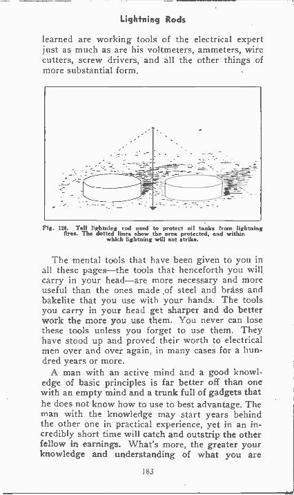
Lightning Rods
learned are working tools of the electrical expertjust as much as are his voltmeters, ammeters, wirecutters, screw drivers, and all the other things ofmore substantial form.
Fig. 126. Tall lightning rod used to protect oil tanks from lightningfires. The dotted lines show the area protected, and within
which lightning will not strike.
The mental tools that have been given to you inall these pages-the tools that henceforth you willcarry in your head-are more necessary and moreuseful than the ones made of steel and brass andbakelite that you use with your hands. The toolsyou carry in your head get sharper and do betterwork the more you use them. You never can losethese tools unless you forget to use them. Theyhave stood up and proved their worth to electricalmen over and over again, in many cases for a hun-dred years or more.
A man with an active mind and a good knowl-edge of basic principles is far better off than onewith an empty mind and a trunk full of gadgets thathe does not know how to use to best advantage. Theman with the knowledge may start years behindthe other one in practical experience, yet in an in-credibly short time will catch and outstrip the otherfellow in earnings. What's more, the greater yourknowledge and understanding of what you are
183
Lightning Rods
doing the greater will be the pleasure and excitement in doing electrical work.
If you feel that you have not remembered all ofthe dozens of facts that have been explained in pre-ceding pages, don't let that worry you. Most, if notall, of them are stored away somewhere in the backof your mind. The day you need them on the jobthey will come popping out to help. And eventhough you don't remember every detail, at leastyou will remember that the point was covered inyour Reference Set, and all you need do is lookback to one of the sections and there you have it.
In our preliminary studies we have gone overmany very simple things relating to electricity, andhave encountered others which are not so simple.In the job instructions which follow we shall com-mence with the simplest kind of work-that of in-stalling electric signals of various kinds. Such workis not only profitable and interesting, but it bringsout many things with which it is essentail that youhave experience before tackling some of the biggerjobs which come later.
184
ELECTRIC SIGNAL SYSTEMS
While Electric Signal and Alarm work is a fieldof tremendous importance, many of these installa-tions operate on low voltages, and because of this,a student, in his eagerness to get into the moreadvanced work, is sometimes liable to overlookthe opportunities in this field. Therefore, beforewe get into the actual study material on thisEquipment and these installations, and to morefully appreciate the opportunities for both full andspare time work installing, repairing and servicingsignal and alarm systems of all kinds, let us justlOok at a few ,facts to help us understand and ap-preciate the importance of this branch of Electricity,where hundreds of thousands of dollars are beingspent each year.
OPPORTUNITIES IN THE SIGNAL FIELDFirst, we must remember that there are many
thousands of new homes being built every year.In addition to the regular electric wiring whichmust be done, there is also a great deal' of lowvoltage work, such as the installation of door bellsand buzzers, burglar alarms, fire alarm systems,etc. This one field alone requires the expenditureof hundreds of thousands of dollars every year, andas this work is very profitable, it offers theTRAINED MAN a wonderful chance to add to hisincome even while he -is learning
Second, there are the millions of homes alreadybuilt which now have door bell and buzzetr sys-tems, fire alarms, etc., which provide another fieldfor spare time earnings in repairing and servicingof these installations in order to keep them in goodoperating condition.
Third, in addition to private homes and resi-dences, there are many thousands of stores, office
185
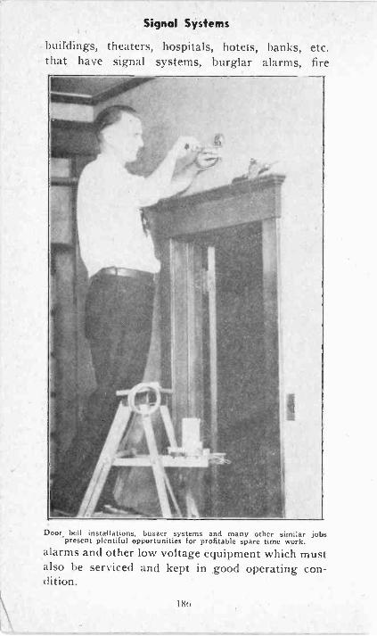
Signal Systems
buildings, theaters, hospitals, hotels, banks, etc.that have signal systems, burglar alarms, fire
Door bell installations, buzzer systems and many other similar jobs'present plentiful opportunities for profitable spare time work.
alarms and other low voltage equipment which mustalso be serviced and kept in good operating con-dition.
18(i
Signal Systems
Fourth, besides the spare time earnings thatare possible in installing and repairing these de-vices and systems, a good plan, and one that willprovide you with a steady income is to make anarrangement with the owners of homes, stores,office, etc. to keep their signal systems and lowvoltage equipment in good operating conditionfor a certain amount of money each year. Thecost to the owner is small and the service hereceives is well worth the small amount invested.
This is in teality a form of maintenance contractwork, in which you agree to keep certain equip-ment in good operating condition for a certainamount of money each year. This means that youwill have to make certain periodical inspectionsand answer all service calls that come from theowners of such equipment, during the terms of thecontract.
train control equipment, etc., provide additionalopportunities for the man who has the right kindof training to enable him to do this work.
Sixth, the signal field in electricity. is one of thebest ways in which a fellow can start an electricalbusiness of his own. It requires very little moneyto start a business of installing alarm and signalequipment. The cost of apparatus and equipmentis small, which means that most of the moneythat you will receive for these jobs will be for yourtime and labor.
Seventh, in addition to these opportunities forincreasing your income and earning power, thisinstruction and training in electric signal work,alarm systems, etc., are valuable for another veryimportant reason. The things that you will learnin these lessons will be of untold benefit to you
187
Signal Systems
later on, in studying such subjects as power plantwork, etc. For example, a small bell -ringing trans-former operates on exactly the same principlesas a large power transformer, and is of course,much easier for the beginner to work on and tounderstand.
SIMPLE CALL BELL
One of the simplest of all signal systems, is theordinary door bell or call bell.
Such an installation requires an ordinary bell, adry cell, a switch, and a few pieces of wire as shownin Figure 1.
Note how the three devices are connected to-gether in a single series circuit. One wire leadsfrom the positive terminal of the cell to the right -baud bell terminal, one from the left bell terminalto the switch, and one returning from the switchto the negative cell terminal, thus completing theelectrical circuit when the switch is closed.
In an actual installation, of course, these wireswould be much longer, as the button would belocated at the door, and the dry cell and bell prob-ably near together somewhere in a rear room ofthe house.
This same system can be used for an officecall with the button located on a certain desk, andthe bell at another desk or office where a party isto be called. The battery can be located at eitherend of the circuit, equally well.
This circuit can also be used for a shop call, ofa burglar alarm or fire alarm, by replacing the pushbutton switch with a special door or window switch,or thermal switch, all of which will be explainedlater.
So we find that this very simple system has avariety of valuable uses.
188
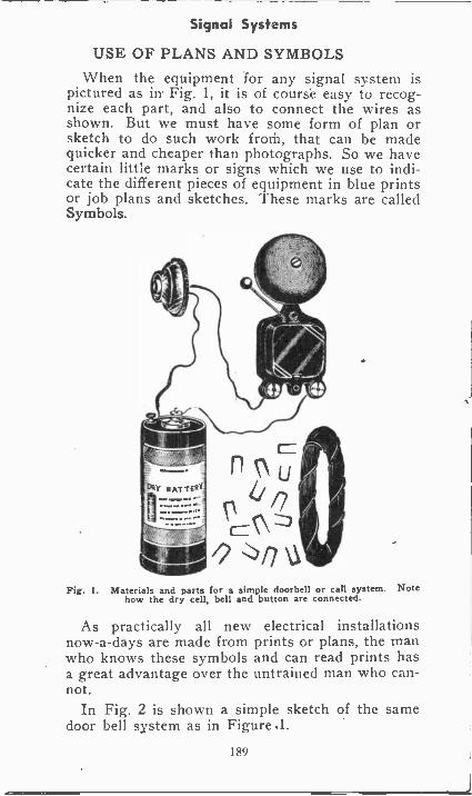
Signal Systems
USE OF PLANS AND SYMBOLS
When the equipment for any signal system ispictured as in' Fig. 1, it is of course easy to recog-nize each part, and also to connect the wires asshown. But we must have some form of plan orsketch to do such work froth, that can be madequicker and cheaper than photographs. So we havecertain little marks or signs which we use to indi-cate the different pieces of equipment in blue printsor job plans and sketches. These marks are calledSymbols.
Fig. I. Materials and parts for a simple doorbell or call system. Notehow the dry cell, bell and button are connected.
As practically all new electrical installationsnow -a -days are made from prints or plans, the rrranwho knows these symbols and can read prints hasa great advantage over the untrained man who can-not.
In Fig. 2 is shown a simple sketch of the samedoor bell system as in Figure .1.
189
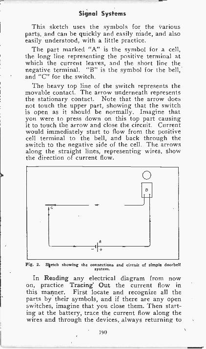
Signal Systems
This sketch uses the symbols for the variousparts, and can be quickly and easily made, and alsoeasily understood, with a little practice.
The part marked "A" is the symbol for a cell,the long line representing the positive terminal atwhich the current leaves, and the short line thenegative terminal. "B" is the symbol for the bell,and "C" for the switch.
The heavy top line of the switch represents themovable contact. The arrow underneath representsthe stationary contact. Note that the arrow doesnot touch the upper part, showing that the switchis open as it should be normally. Imagine thatyou were to press down on this top part causingit to touch the arrow and close the circuit. Currentwould immediately start to flow from the positivecell terminal to the bell, and back through theswitch to the negative side of the cell. The arrowsalong the straight lines, representing wires, showthe direction of current flow.
Fig. 2. Sketch showing the connections and circuit of simple doorbellsystem.
In Reading any electrical diagram from nowon, practice Tracing Out the current flow inthis manner. First locate and recognize all theparts by their symbols, and if there are any openswitches, imagine that you close them. Then start-ing at the battery, trace the current flow along thewires and through the devices, always returning to
190
-0-
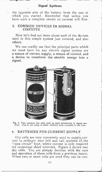
Signal Systems
the opposite side of the battery from the one atwhich you started. Remember that unless youhave such a complete circuit no current will flow.
3. COMMON DEVICES IN SIGNALCIRCUITS
Now let's find out more about each of the devicesused in this simple system just covered, and alsoothers.
We can readily see that the principal parts whichwe must have for any electric signal system area source of current supply, a means of control, anda device to transform the electric energy into asignal.
Fig. 3. Two common dry cells such a used extensively in signal sys-tems. One is cut away to show terminal strip attached to the zinc.
4. BATTERIES FOR CURRENT SUPPLY
Dry cells are very commonly used to supply, cur-rent to ordinary door bell and call systems of, the"open circuit" type, where current is only requiredfor occasional short intervals. Figure 3 shows twodry cells. You are already familiar with the careand operation of these cells from a previous lesson.When two or more cells are used they can be con -
191
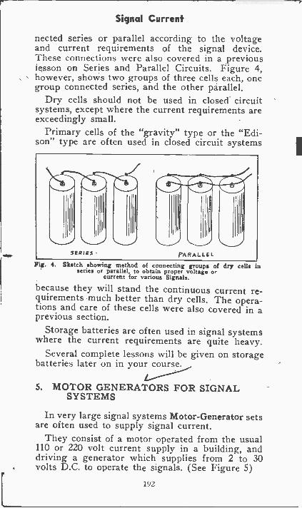
Signal Current
nected series or parallel according to the voltageand current requirements of the signal device.These connections were also covered in a previouslesson on Series and Parallel Circuits. Figure 4,however, shows two groups of three cells each, onegroup connected series, and the other parallel.
Dry cells should not be used in closed circuitsystems, except where the current requirements areexceedingly small.
Primary cells of the "gravity" type or the "Edi-son" type are often used in closed circuit systems
Fig. 4. Sketch showing method of connecting groups of dry cells inseries or parallel, to obtain proper voltage or
current for various Signals.
because they will stand the continuous current re-quirements much better than dry cells. The opera-tions and care of these cells were also covered in aprevious section.
Storage batteries are often used in signal systemswhere te current requirements are quite heavy.
Several complete lessons will be given on storagebatteries later on in your course.
5. MOTOR GENERATORS FOR SIGNALSYSTEMS
In very large signal systems Motor -Generator setsare often used to supply signal current.
They consist of a motor operated from the usual110 or 220 volt current supply in a building, anddriving a generator which supplies from 2 to 30volts D.C. to operate the signals. (See Figure 5)
192
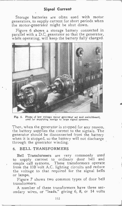
Signal Current.
Storage batteries are often used with motorgenerators, to supply current for short periods whenthe motor -generator might be shut down.
Figure 6 shows a storage battery connected inparallel with a D.C. generator so that the generator,while operating, will keep the battery fully charged.
Fig. 5. Photo of low voltage motor generator set and switchboard,used for supplying energy to large signal systems.
Then, when the generator is stopped for any reason,the battery supplies the current to the signals. Thegenerator should be disconnected frorri the batterywhen it is stopped, so the battery will not dischargethrough the generator winding.
6. BELL TRANSFORMERS
Bell Transformers are very commonly usedto supply current to ordinary door bell andsimple call systems. These transformers operatefrom the 110 volt A.C. lighting circuits and reducethe voltage to that required for the signal bellsor lamps.
Figure 7 shows two common types of door belltransformers.
A number of these transformers have three sec-ondary wires, or "leads." giving 6, 8, or 14 volts
193
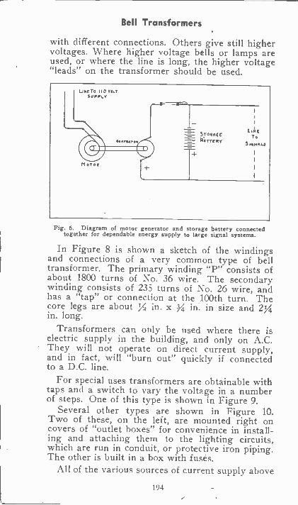
Bell Transformers
with different connections. Others give still highervoltages. Where higher voltage bells or lamps areused, or where the line is long, the higher voltage"leads" on the transformer should be used.
Fig. 6. Diagram of motor generator and storage battery connectedtogether for dependable energy supply to large signal systems.
In Figure 8 is shown a sketch of the windingsand connections of a very common type of belltransformer. The primary winding "P" consists ofabout 1800 turns of No. 36 wire. The secondarywinding consists of 235 turns of No. 26 wire, andhas a "tap" or connection at the .100th turn. Thecore legs are about 1/2 in. x 3/4 in. in size and 2%in. long.
Transformers can only be used where there iselectric supply in the building, and only on A.C.They will not operate on direct current supply,and in fact, will "burn out" quickly if connectedto a D.C. line.
For special uses transformers are obtainable withtaps and a switch to vary the voltage in a numberof steps. One of this type is shown in Figure 9.
Several other types are shown in Figure 10.Two of these, on the left, are mounted right oncovers of "outlet boxes" for convenience in install-ing and attaching them to the lighting circuits,which are run in conduit, or protective iron piping.The other is built in a box with fuses.
All of the various sources of current supply above
194
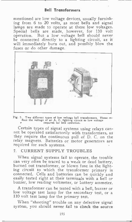
Bell Transformers
mentioned are low voltage devices, usually furnish-ing from 6 to 20 volts, as most bells and signallamps are made to operate at these low voltages.Special bells are made, however, for 110 voltoperation. But a low voltage bell should neverbe connected directly to a lighting circuit, as itwill immediately burn out, and possibly blow thefuses or do other damage.
Fig. 7. Two different types of low voltage bell transformers. These re-duce the voltage of an A. C. lighting circuit to low voltage
required for bell operation.
Certain types of signal systems using relays can-not be operated satisfactorily with transformers, asthey require the continuous pull of D. C. on therelay magnets. Batteries or motor generators arerequired for such systems.7. CURRENT SUPPLY TROUBLES
When signal systems fail to operate, the troublecan very often be traced to a weak or dead battery,burned out transformer, or blown fuse in the light-ing circuit to which the transformer primary isconnected. Cells and batteries can be quickly andeasily tested right at their terminals with a bell orbuzzer, low reading voltmeter, or battery ammeter.
A transformer can be tested with a bell, buzzer orlow voltage test lamp for the secondary test, or a110 volt test lamp for the primary test.
When "shooting" trouble on any defective signalsystem, you should never fail to check the source
195
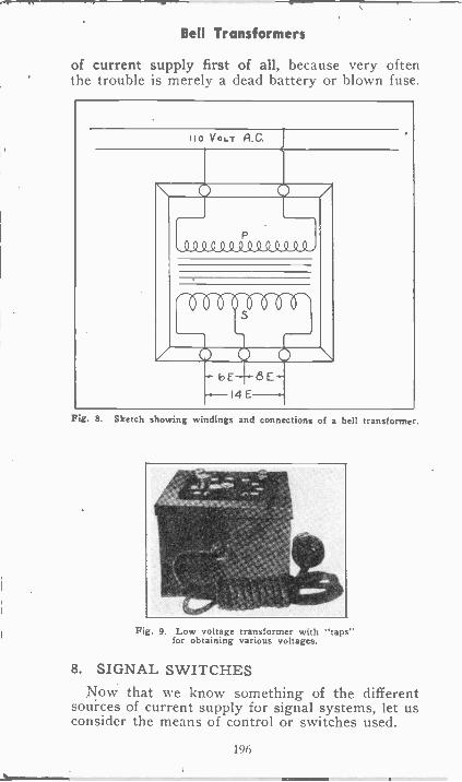
Bell Transformers
of current supply first of all, because very oftenthe trouble is merely a dead battery or blown fuse.
110 VOLT A.0
P0Q0Q.Q0Q000000i
bE 6E-14E
Fig. 8. Sketch showing windings and connections of a bell transformer.
Fig. 9. Low voltage transformer with "taps"for obtaining various voltages.
8. SIGNAL SWITCHESNow that we know something of the different
sources of current supply for signal systems, let usconsider the means of control or switches used.
196
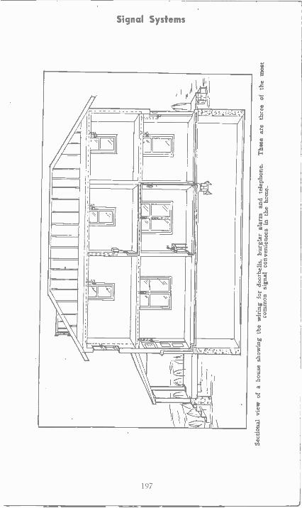
,,,i
A4
IA
A-
,
I aLI
41"
0
.:'
Sect
iona
l vie
w o
f a
hous
e sh
owin
g th
e w
irin
g fo
r do
orbe
lls, b
urgl
ar a
larm
and
tele
phon
e.T
hese
are
thre
e of
the
mos
tco
mm
on s
igna
l con
veni
ence
s in
the
hom
e.
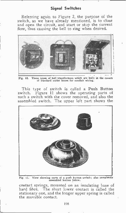
Signal Switches
Referring again to Figure 2, the purpose of theswitch, as we have already mentioned, is to closeand open the circuit, and start or stop the currentflow, thus causing the bell to ring when desired.
J
Fig. 10. Three types of bell transformers which are built in the coversof standard outlet boxes for conduit wiring.
This type of switch is called a Push Buttonswitch. Figure 11 shows the operating parts ofsuch a switch with the cover removed, and also theassembled switch. The upper left part shows the
Fig. 11. View showing parts of a push button switch; also completelyassembled button below.
contact springs, mounted on an insulating base ofhard fibre. The short lower contact is called thestationary one, and the longer upper spring is calledthe movable contact.
198
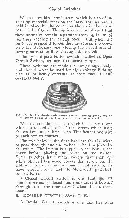
Signal Switches
When assembled, the button, which is also of in-sulating material, rests on the large springs and isheld in place by the cover, as shown in the lowerpart of the figure. The springs are so shaped thatthey normally remain separated from y8 in. to Yiin., thus keeping the circuit open. But when thebutton is pressed it forces the movable spring downonto the stationary one, closing the circuit and al-lowing current to flow through the switch.
This type of push button switch is called an OpenCircuit Switch, because it is normally open.
These switches are made for low voltages only,and should never be used for high voltage lightingcircuits, or heavy currents, as they may arc andoverheat badly.
Fig. 12. Double circuit push button switch, showing clearly the ar-rangement of contacts and parts with respect to base and cover.
When connecting such a switch in a circuit, onewire is attached to each of the screws which havethe washers under their heads. This fastens one wireto each switch contact.
The two holes in the fibre base are for the wiresto pass through, and the switch is held in place bythe cover. The button is slipped in the hole in thecover before placing the cover on the switch.Some switches have metal covers that snap on,while others have wood covers that screw on. Inaddition to this common open circuit switch, wehave "closed circuit" and "double circuit" push but-ton switches.
A Closed Circuit switch is one that has itscontacts normally closed, and some current flowingthrough it all the time except when it is pressedopen.9. DOUBLE CIRCUIT SWITCHES
A Double Circuit switch is one that has both
199
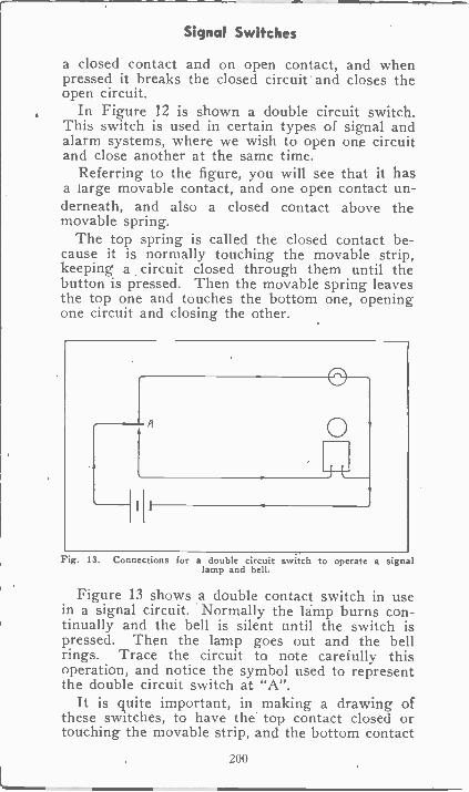
Signal Switches
a closed contact and on open contact, and whenpressed it breaks the closed circuit and closes theopen circuit.
In Figure 12 is shown a double circuit switch.This switch is used in certain types of signal andalarm systems, where we wish to open one circuitand close another at the same time.
Referring to the figure, you will see that it hasa large movable contact, and one open contact un-derneath, and also a closed contact above themovable spring.
The top spring is called the closed contact be-cause it is normally touching the movable strip,keeping a circuit closed through them until thebutton is pressed. Then the movable spring leavesthe top one and touches the bottom one, openingone circuit and closing the other.
Fig. 13. Connections for a double circuit switch to operate a signallamp and bell.
Figure 13 shows a double contact switch in usein a signal circuit. Normally the lamp burns con-tinually and the bell is silent until the switch ispressed. Then the lamp goes out and the bellrings. Trace the circuit to note carefully thisoperation, and notice the symbol used to representthe double circuit switch at "A".
It is quite important, in making a drawing ofthese switches, to have the top contact closed ortouching the movable strip, and the bottom contact
200
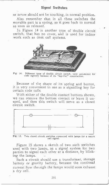
Signal Switches
or arrow should not be touching, in normal position.Also remember that in all these switches the
movable part is a spring, so it goes back to normalas soon as released.
In Figure 14 is another type of double circuitswitch, that has no cover, and is used for indoorwork such as desk call systems.
Fig. 14. Different type of double circuit switch, very convenient forcode signally because of its "key -like" construction.
Because of the shape of its spring and button,it is very convenient to use as a signalling key forcertain code calls.
With either of the double contact buttons shown,we can remove the bottom contact or leave it un-used, and then this switch will serve as a closedcircuit switch.
Fig. 15. Two closed circuit switches connected with lamps for a returncall signal.
Figure 15 shows a sketch of two such switchesused with two lamps, as a signal system for twoparties to signal each other at a distance, by blink-ing the lamps.
Such a circuit should use a transformer, storagebattery or gravity battery, because the continualcurrent flow through the lamps would soon exhausta dry cell.
201
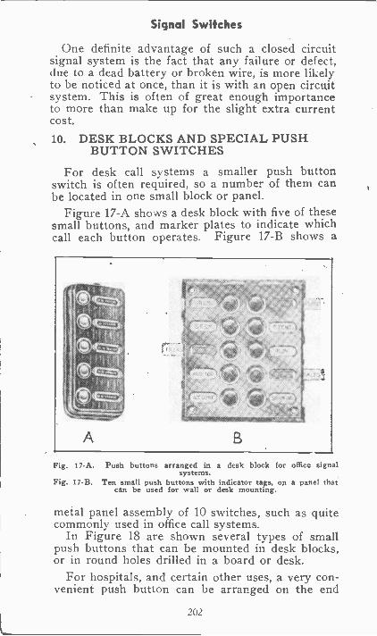
Signal Switches
One definite advantage of such a closed circuitsignal system is the fact that any failure or defect,due to a dead battery or broken wire, is more likelyto be noticed at once, than it is with an open circuitsystem. This is often of great enough importanceto more than make up for the slight extra currentcost.
10. DESK BLOCKS AND SPECIAL PUSHBUTTON SWITCHES
For desk call systems a smaller push buttonswitch is often required, so a number of them canbe located in one small block or panel.
Figure 17-A shows a desk block with five of thesesmall buttons, and marker plates to indicate whichcall each button operates. Figure 17-B shows a
A
Fig. 17-A. Push buttons arranged in a desk block for office signalsystems.
Fig. 17-B. Ten small push buttons with indicator tags, on a panel thatcan be used for wall or desk mounting.
metal panel assembly of 10 switches, such as quitecommonly used in office call systems.
In Figure 18 are shown several types of smallpush buttons that can be mounted in desk blocks,or in round holes drilled in a board or desk.
For hospitals, and certain other uses, a very con-venient push button can be arranged on the end
202
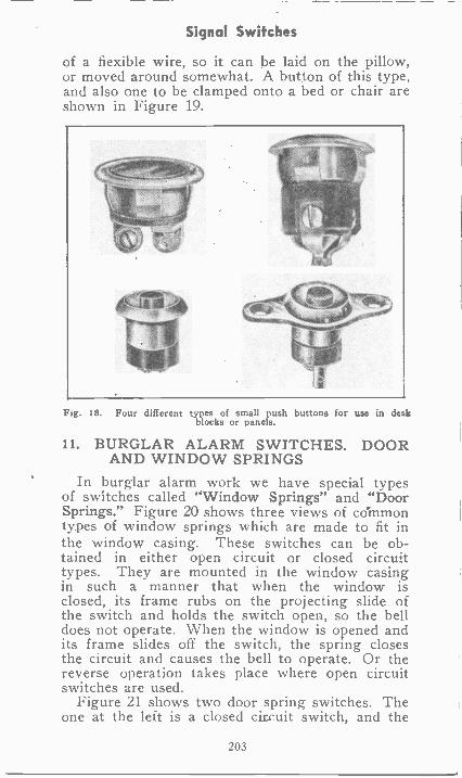
Signal Switches
of a flexible wire, so it can be laid on the pillow,or moved around somewhat. A button of this type,and also one to be clamped onto a bed or chair areshown in Figure 19.
Fig. 18. Four different types of small push buttons for use in deskblocks or panels.
11. BURGLAR ALARM SWITCHES. DOORAND WINDOW SPRINGS
In burglar alarm work we have special typesof switches called "Window Springs" and "DoorSprings." Figure 20 shows three views of commontypes of window springs which are made to fit inthe window casing. These switches can be ob-tained in either open circuit or closed circuittypes. They are mounted in the window casingin such a manner that when the window isclosed, its frame rubs on the projecting slide ofthe switch and holds the switch open, so the belldoes not operate. When the window is opened andits frame slides off the switch, the spring closesthe circuit and causes the bell to operate. Or thereverse operation takes place where open circuitswitches are used.
Figure 21 shows two door spring switches. Theone at the left is a closed circuit switch, and the
203
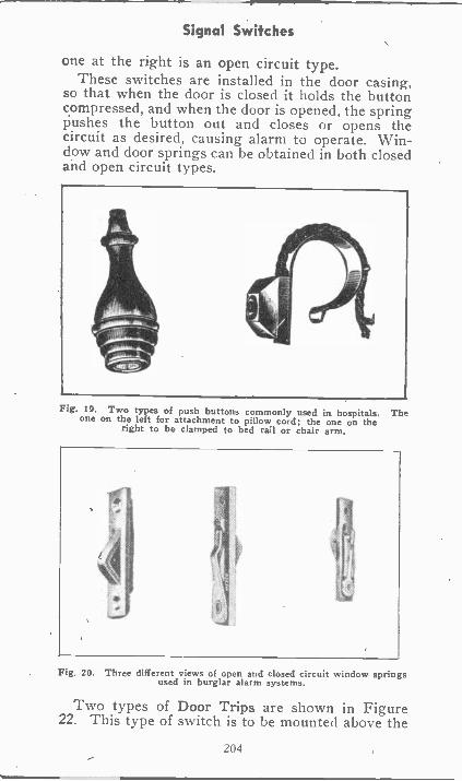
Signal Switches
one at the right is an open circuit type.These switches are installed in the door casing,
so that when the door is closed it holds the buttoncompressed, and when the door is opened, the springPushes the button out and closes or opens thecircuit as desired, causing alarm to operate. Win-dow and door springs can be obtained in both closedand open circuit types.
Fig. 19. Two types of push buttons commonly used in hospitals. Theone on the left for attachment to pillow cord; the one on the
right to be clamped to bed rail or chair arm.
Fig. 20. Three different views of open and closed circuit window springsused in burglar alarm systems.
Two types of Door Trips are shown in Figure22. This type of switch is to be mounted above the
204
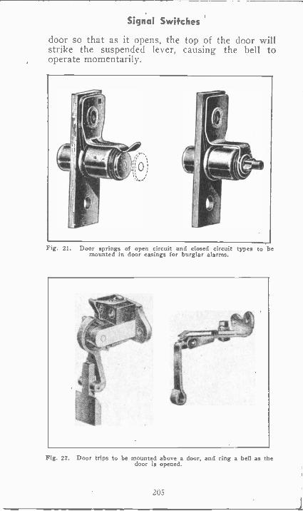
Signal Switches
door so that as it opens, the top of the door willstrike the suspended lever, causing the bell tooperate momentarily.
Fig. 21. Door springs of open circuit and closed circuit types to bemounted in door casings for burglar alarms.
Fig. 22. Door trips to be mounted above a door, and ring a bell as thedoor is opened.
205
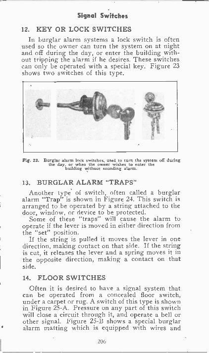
Signal Switches
12. KEY OR LOCK SWITCHESIn burglar alarm systems a lock switch is often
used so the owner can turn the system on at nightand off during the day, or enter the building with-out tripping the alarm if he desires. These switchescan only be operated with a special key. Figure 23shows two switches of this type.
Fig. 23. Burglar alarm lock switches, used to turn the system off duringthe day, or when the owner wishes to enter the
building without sounding alarm.
13. BURGLAR ALARM "TRAPS"Another type of switch, often called a burglar
alarm "Trap" is shown in Figure 24. This switch isarranged to be operated by a string attached to thedoor, window, or device to be protected.
Some of these "traps" will cause the alarm tooperate if the lever is moved in either direction fromthe "set" position.
If the string is pulled it moves the lever in onedirection, making contact on that side. If the stringis cut, it releases the lever and a spring moves it inthe opposite direction, making a contact on thatside.
14. FLOOR SWITCHESOften it is desired to have a signal system that
can be operated from a concealed floor switch,under a carpet or rug. A switch of this type is shownin Figure 25-A. Pressure on any part of this switchwill close a circuit through it, and operate a bell orother signal. Figure 25-B shows a special burglaralarm matting which is equipped with wires and
206
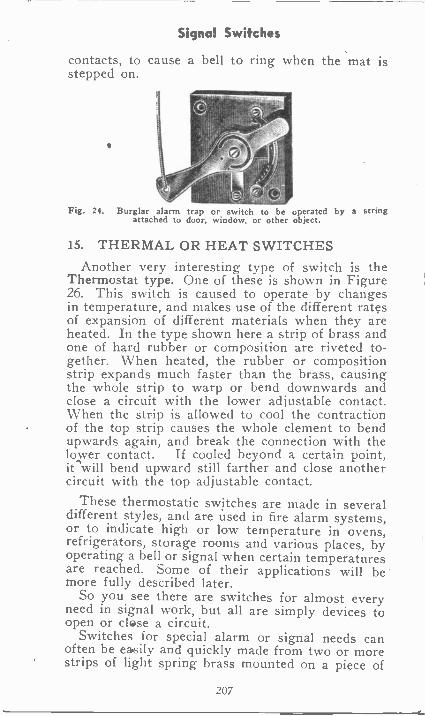
Signal Switches
contacts, to cause a bell to ring when the mat isstepped on.
Fig. 24. Burglar alarm trap or switch to be operated by a stringattached to door, window, or other object.
15. THERMAL OR HEAT SWITCHESAnother very interesting type of switch is the
Thermostat type. One of these is shown in Figure26. This switch is caused to operate by changesin temperature, and makes use of the different ratesof expansion of different materials when they areheated. In the type shown here a strip of brass andone of hard rubber or composition are riveted to-gether. When heated, the rubber or compositionstrip expands much faster than the brass, causingthe whole strip to warp or bend downwards andclose a circuit with the lower adjustable contact.When the strip is allowed to cool the contractionof the top strip causes the whole element to bendupwards again, and break the connection with thelower contact. If cooled beyond a certain point,it -swill bend upward still farther and close anothercircuit with the top adjustable contact.
These thermostatic switches are made in severaldifferent styles, and are used in fire alarm systems,or to indicate high or low temperature in ovens,refrigerators, storage rooms and various places, byoperating a bell or signal when certain temperaturesare reached. Some of their applications will bemore fully described later.
So you see there are switches for almost everyneed in signal work, but all are simply devices toopen or close a circuit.
Switches for special alarm or signal needs canoften be easily and quickly made from two or morestrips of light spring brass mounted on a piece of
207
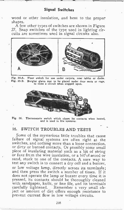
Signal Switches
wood or other insulation, and bent to the propershapes.
A few other types of switches are shown in Figure27. Snap switches of the type used in lighting cir-cuits are sometimes used in signal circuits also.
Fig. 2S -A. Floor switch for use under carpets, near tables or desks.Fig. 25-B. Burglar alarm mat to be placed under door mats or rugs,
to close a circuit when stepped upon.
Fig. 26. Thermostatic switch which closes its contacts when heated,and is used in fire systems.
16. SWITCH TROUBLES AND TESTSSome of the mysterious little troubles that cause
failure of signal systems are often right at theswitches, and nothing more than a loose connection,or dirty or burned contacts. Or possibly some smallpiece of insulating material such as a bit of stringor fuzz frcm the wire insulation, or a bit of wood orsand, stuck to one of the contacts. A sure way totest any switch is to connect a dry cell and a buzzer,or low voltage lamp, directly across its terminals;and then press the switch a number of times. If itdoes not operate the lamp or buzzer every time it ispressed, its contacts should be thoroughly cleanedwith sandpaper, knife, or fine file, and its terminalscarefully tightened. Remember a very small ob-ject or amount of dirt offers enough resistance toprevent current flow in low voltage circuits.
208
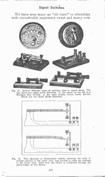
Signal Switches
We have seen many an "old timer" or electricianwith considerable experience sweat and worry over
Fig. 27. Several different types of switches used in signal work. Thetwo above are called Lever Switches. In the center on the left is aMultiple Key Switch; at the right double circuit Lever Switch.
Below are two Knife Blade Switches.
)))13133:4592=1""=)12!),',Z)219),,: ,
Fig. 28. Two sketches of thermostatic switch, showing the strip innormal position in the upper view, and warped to close the contactsin the lower view. Note how the circuit is completed through themetal frame of this device.
209
Signal Switches
something of this same nature. But with a knowl-edge of circuit principles, Ohms Law, and thesesimple definite tests, such troubles can be "corner-ed" and need not be so mysterious to the man withtr aining.
' EXAMINATION QUESTIONS
1. Why are symbols used in wiring plans insteadof actual pictures?
2. What are the principle parts needed for an elec-triC signal system?
3. What kind of primary cells would you selectfor use on a closed circuit system?
4. What purpose does the bell transformer servein door bell systems?
5. What purpose does the switch serve in a signalsystem?
6. Would you select an open or a closed circuitswitch for' use on a simple door bell circuit?
7. Are the contacts in a closed circuit switch nor-mally open or closed?
8. Describe a double contact switch.
9. Name two uses for a thermostatic switch.
10. What arc the most common troubles whichcause push button switches to fail?
210
SIGNAL EQUIPMENT
1. SIGNAL BELLS AND LAMPSThe purpose of any signal or alarm system, is
to call the attention of someone. To do this we canuse either an "audible" or "visible" signal, or quiteoften a combination of both. By an audible signal,we mean one that creates sound loud enough to beheard by those whose, attention is desired. Bells,buzzers, and horns are used for this purpose. Visi-ble signals are those that are to attract the eye,such as lamps, or semaphores. The term "sema-phore" means a sort of moving flag or shutter.
Visible signals as a rule can only be used wherethey are in front of, or in line with the vision ofthose whose attention is desired, and are most com-monly used where an operator or attendant iswatching for them continually.
Electric bells are very commonly used in alltypes of signal systems.
Their construction and operation is quite simpleand yet very interesting, and important to know.
2. VIBRATING BELLSThere are several different types of bells, but the
Series Vibrating Bell is the most commonly usedof any. Figure 1 shows a good view of such a bellwith the cover removed, showing the coils andparts.
Examine this carefully and compare it withFigure 2, which is a sketch of the same type ofbell, and shows the electrical circuit and operatingprinciple clearly. Note how easy it is to recognizeeach part in the photo, from the simple symbols inthe sketch, and how the sketch really shows somethings more clearly than the actual photograph."A" and "A" are the bell terminals to which thewires are fastened. "B" "B" are the cores and coilsor electro-magnets, which attract or operate thearmature "C". "D" is a spring which supportsthe armature and also pulls it back every time themagnets release it. "E" is the end of the samespring, on which is mounted a piece of special alloy
211
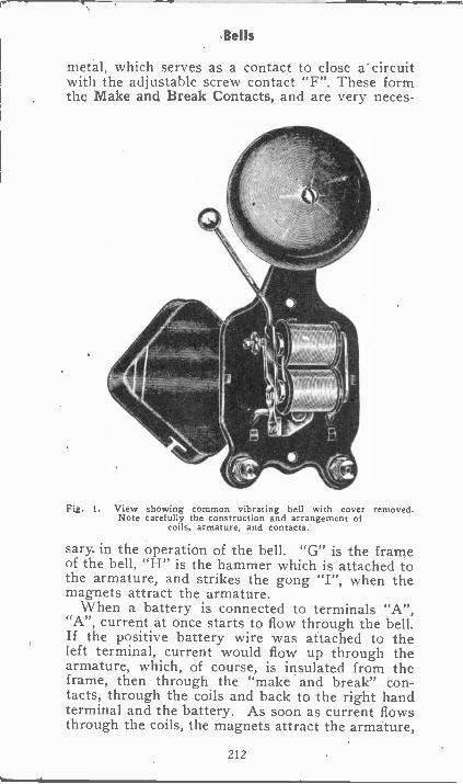
Bells
metal, which serves as a contact to close a circuitwith the adjustable screw contact "F". These formthe Make and Break Contacts, and are very neces-
Fig. 1. View showing common vibrating bell with cover removed.Note carefully the construction and arrangement of
coils, armature, and contacts.
sary. in the operation of the bell. "G" is the frameof the bell, "H" is the hammer which is attached tothe armature, and strikes the gong "I", when themagnets attract the armature.
When a battery is connected to terminals "A","A", current at once starts to flow through the bell.If the positive battery wire was attached to theleft terminal, current would flow up through thearmature, which, of course, is insulated from theframe, then through the "make and break" con-tacts, through the coils and back to the right handterminal and the battery. As soon as current flowsthrough the coils, the magnets attract the armature,
212
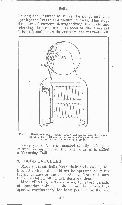
Bells
causing the hammer to strike the gong, and alsoopening the "make and break" contacts. This stopsthe flow of current, demagnetizing the coils andreleasing the armature. As soon as the armaturefalls back and closes the contacts, the magnets pull
Fig. 2. Sketch showing electrical circuit and connections of commonvibrating bell. Observe very carefully the parts of this
diagram, and the explanation given.
it away again. This is repeated rapidly as long ascurrent is supplied to the bell ; thus it is calleda Vibrating Bell.
3. BELL TROUBLESMost of. these bells have their coils wound for
6 to 10 volts, and should not be operated on muchhigher voltage or the coils will overheat and burntheir insulation off, which destroys them.
Most vibrating bells are made for short periodsof operation only, and should not be allowed tooperate continuously for long periods, or the arc
213
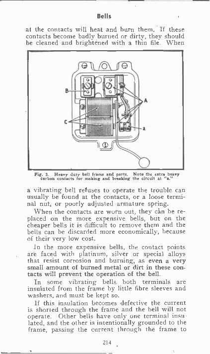
Bells
at the contacts will heat and burn them. If thesecontacts become badly burned or dirty, they shouldbe cleaned and brightened with a thin file. When
Fig. 3. Heavy duty bell frame and parts. Note the extra heavycarbon contacts for making and breaking the circuit at "a."
a vibrating bell refuses to operate the trouble canusually be found at the contacts, or a loose termi-nal nut, or poorly adjusted armature spring.
When the contacts are worn out, they can be re-placed on the more expensive bells, but on thecheaper bells it is difficult to remove them and thebells can be discarded more economically, becauseof their very low cost.
In the more expensive bells, the contact pointsare faced with platinum, silver or special alloysthat resist corrosion and burning, as even a verysmall amount of burned metal or dirt in these con-tacts will prevent the operation of the bell.
In some vibrating bells both terminals areinsulated from the frame by little fibre sleeves andwashers, and must be kept so.
If this insulation becomes defective the currentis shorted through the frame and the bell will notoperate. Other bells have only one terminal insu-lated, and the other is intentionally grounded to theframe, passing the current through the frame to
214
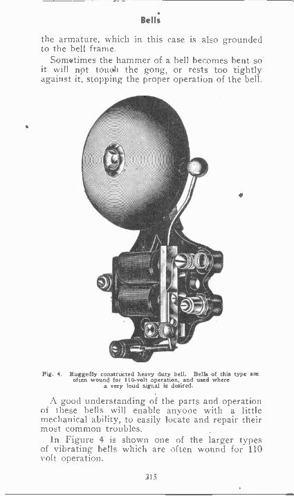
Bells
the armature, which in this case is also groundedto the bell frame.
Sometimes the hammer of a bell becomes bent soit will not touoh the gong, or rests too tightlyagainst it, stopping the proper operation of the bell.
Fig. 4. Ruggedly constructed heavy duty bell. Bells of this type areoften wound for 110 -volt operation, and used where
a very loud signal is desired.
A good understanding of the parts and operationof these bells will enable anyone with a littlemechanical ability, to easily locate and repair theirmost common troubles.
In Figure 4 is shown one of the larger typesof vibrating bells which are often wound for 110volt operation.
315
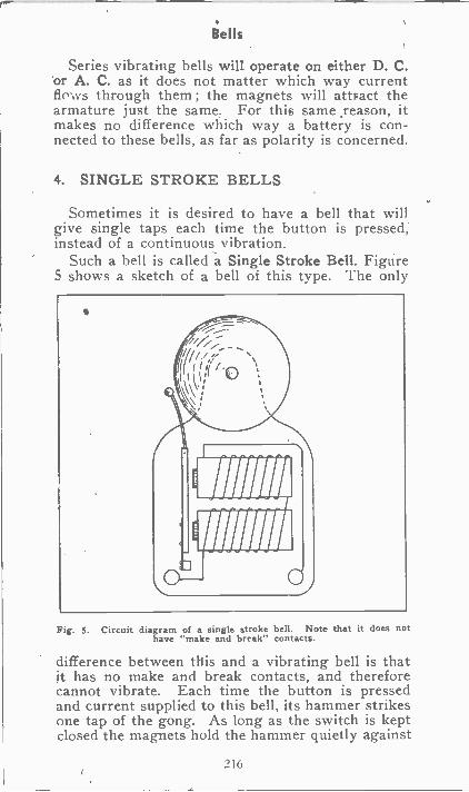
Bells
Series vibrating bells will operate on either D. C.or A. C. as it does not matter which way currentflo-o.'s through them ; the magnets will attsact thearmature just the same. For this same ,reason, itmakes no difference which way a battery is con-nected to these bells, as far as polarity is concerned.
4. SINGLE STROKE BELLS
Sometimes it is desired to have a bell that willgive single taps each time the button is pressed,instead of a continuous vibration.
Such a bell is called a Single Stroke Bell. Figure5 shows a sketch of a bell of this type. The only
VIM
Fig. 5. Circuit diagram of a single stroke bell. Note that it does nothave ''make and break" contacts.
difference between this and a vibrating bell is thatit has no make and break contacts, and thereforecannot vibrate. Each time the button is pressedand current supplied to this bell, its hammer strikesone tap of the gong. As long as the switch is keptclosed the magnets hold the hammer quietly against
216
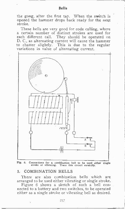
Bells
the gong, after the first tap. When the switch isopened the hammer drops back ready for the nextstroke.
These bells are very good for code calling, wherea certain number of distinct strokes are used foreach different call. They should be operated onD. C., as alternating current will cause the hammerto chatter slightly. This is due to the regularvariations in value of alternating current.
Fig. 6. Connections for a combination bell to be used either sing estroke or vibrating. Trace this circuit carefully.
5. COMBINATION BELLSThere are also combination bells which are
arranged to be used either vibrating or single stroke.Figure 6 shows a sketch of such a bell con-
nected to a battery and two switches, to be operatedeither as a single stroke or vibrating bell as desired.
217
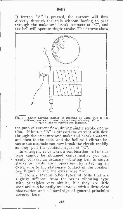
Bells
If button "A" is pressed, the current will flowdirectly through the coils without having to passthrough the make and break contacts at "C", andthe bell will operate single stroke. The arrows show
Fig. 7. Sketch showing method of attaching an extra wire to thestationary contact to convert an ordinary vibrating bell for
single stroke or combination operation.
the path of current flow, during single stroke opera-tion. If button "B" is pressed the current will flowthrough the armature and make and break contacts,and then to the coils, and the bell will vibrate be-cause the magnets can now break the circuit rapidlyas they pull the contacts apart at "C".
In emergencies or when a combination bell of thistype cannot be obtained conveniently, you caneasily convert an ordinary vibrating bell to singlestroke or combination operation, by attaching anextra wire to the stationary contact of the breaker.See Figure 7, and the extra wire "A".
There are several other types of bells that areslightly different from the series vibrating typewith principles very similar, but they are littleused and can be easily understood with a little closeobservation and a knowledge of general principlescovered here.
218
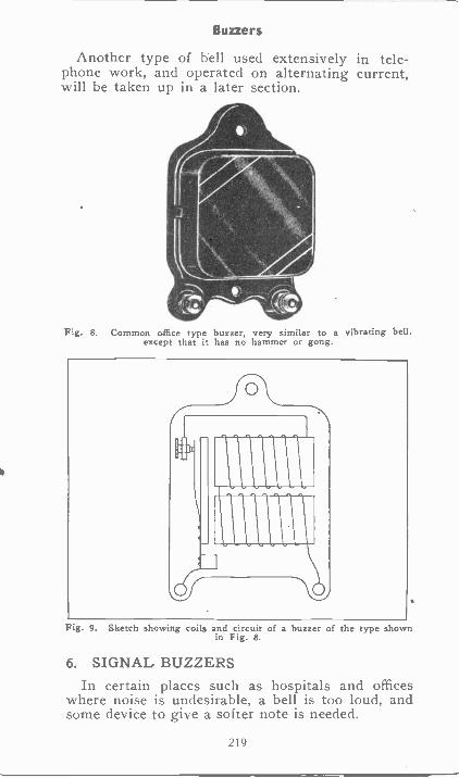
Buzzers
Another type of bell used extensively in tele-phone work, and operated on alternating current,will be taken up in a later section.
Fig. 8. Common office type buzzer, very similar to a vibrating bell,except that it has no hammer or gong.
Fig. 9. Sketch showing coils and circuit of a buzzer of the type shownin Fig. 8.
6. SIGNAL BUZZERSIn certain places such as hospitals and offices
where noise is undesirable, a bell is too loud, andsome device to give a softer note is needed.
219
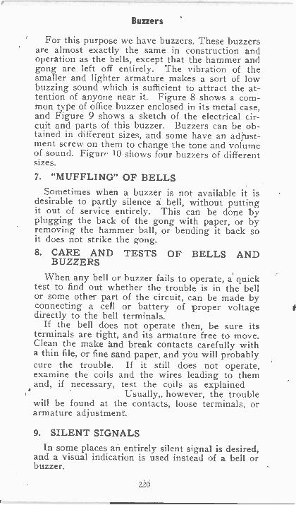
Buzzers
For this purpose we have buzzers. These buzzersare almost exactly the same in construction Andoperation as the bells, except that the hammer andgong are left off entirely. The vibration of thesmaller and lighter armature makes a sort of lowbuzzing sound which is sufficient to attract the at-tention of anyone near it. Figure 8 shows a com-mon type of office buzzer enclosed in its metal case,and Figure 9 shows a sketch of the electrical cir-cuit and parts of this buzzer. Buzzers can be ob-tained in different sizes, and some have an adjust-ment screw on them to change the tone and volumeof sound. Figure 10 shows four buzzers of differentsizes.
7. "MUFFLING" OF BELLSSometimes when a buzzer is not available it is
desirable to partly silence a bell, without puttingit out of service entirely. This can be done byplugging the back of the gong with paper, or byremoving the hammer ball, or bending it back soit does not strike the gong.8. CARE AND TESTS OF BELLS AND
BUZZERS
When any bell or buzzer fails to operate, a quicktest to find out whether the trouble is in the bellor some other part of the circuit, can be made byconnecting a cell or battery of proper voltagedirectly to the bell terminals.
If the bell does not operate then, be sure itsterminals are tight, and its armature free to move.Clean the make and break contacts carefully witha thin file, or fine sand paper, and you will probablycure the trouble. If it still does not operate,examine the coils and the wires leading to themand, if necessary, test the coils as explained
Usually,, however, the troublewill be found at the contacts, loose terminals, orarmature adjustment.
9. SILENT SIGNALSIn some places an entirely silent signal is desired,
and a visual indication is used instead of a bell orbuzzer.
220
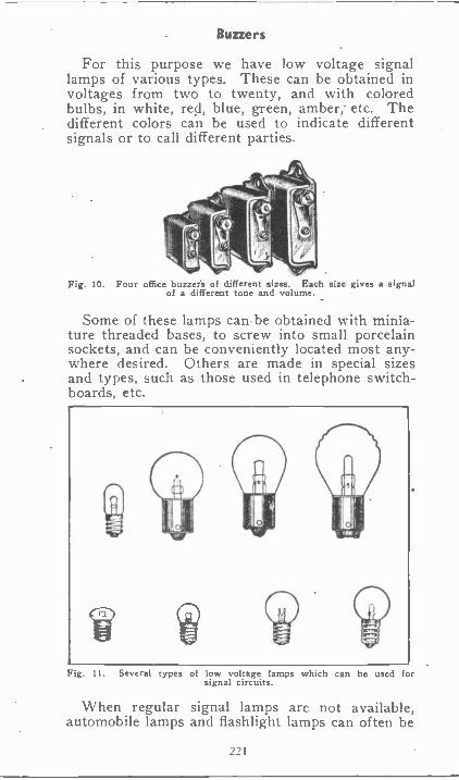
Buzzers
For this purpose we have low voltage signallamps of various types. These can be obtained involtages from two to twenty, and with coloredbulbs, in white, red, blue, green, amber; etc. Thedifferent colors can be used to indicate differentsignals or to call different parties.
Fig. 10. Four office buzzers of different sizes. Each size gives a signalof a different tone and volume.
Some of these lamps canbe obtained with minia-ture threaded bases, to screw into small porcelainsockets, and can be conveniently located most any-where desired. Others are made in special sizesand types, such as those used in telephone switch-boards, etc.
Fig. 11. Several types of low voltage lamps which can be used forsignal circuits.
When regular signal lamps are not available,automobile lamps and flashlight lamps can often be
221
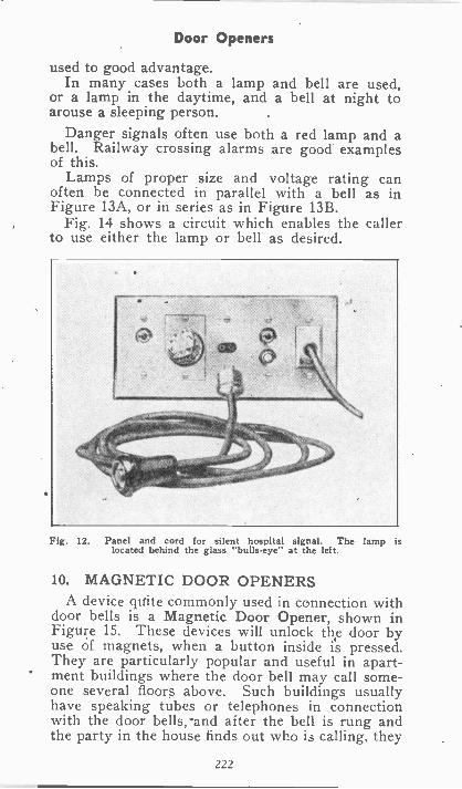
Door Openers
used to good advantage.In many cases both a lamp and bell are used,
or a lamp in the daytime, and a bell at night toarouse a sleeping person.
Danger signals often use both a red lamp and abell. Railway crossing alarms are good examplesof this.
Lamps of proper size and voltage rating canoften be connected in parallel with a bell as inFigure 13A, or in series as in Figure 13B.
Fig. 14 shows a circuit which enables the callerto use either the lamp or bell as desired.
Fig. 12. Panel and cord for silent hospital signal. The lamp islocated behind the glass "bulls -eye" at the left.
10. MAGNETIC DOOR OPENERSA device quite commonly used in connection with
door bells is a Magnetic Door Opener, shown inFigure 15. These devices will unlock the door byuse of magnets, when a button inside is pressed.They are particularly popular and useful in apart-ment buildings where the door bell may call some-one several floors above. Such buildings usuallyhave speaking tubes or telephones in connectionwith the door bells, and after the bell is rung andthe party in the house finds out who is calling, they
222
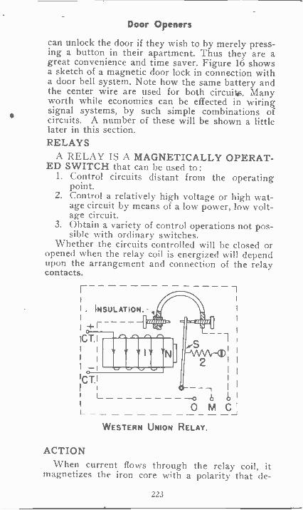
Door Openers
can unlock the door if they wish to by merely press-ing a button in their apartment. Thus they are agreat convenience and time saver. Figure 16 showsa sketch of a magnetic door lock in connection witha door bell system. Note how the same battery andthe center wire are used for both circuits. Manyworth while economies can be effected in wiringsignal systems, by such simple combinations ofcircuits. A number of these will be shown a littlelater in this section.RELAYS
A RELAY IS A MAGNETICALLY OPERAT-ED SWITCH that can be used to:
1. Control circuits distant from the operatingpoint.
2. Control a relatively high voltage or high wat-age circuit by means of a low power, low volt-age circuit.
3. Obtain a variety of control operations not pos-sible with ordinary switches.
Whether the circuits controlled will be closed oropened when the relay coil is energized will dependupon the arrangement and connection of the relaycontacts.
. INSULATION.
WESTERN UNION
ACTIONWhen current flows through the relay coil, it
magnetizes the iron core with a polarity that de-
223
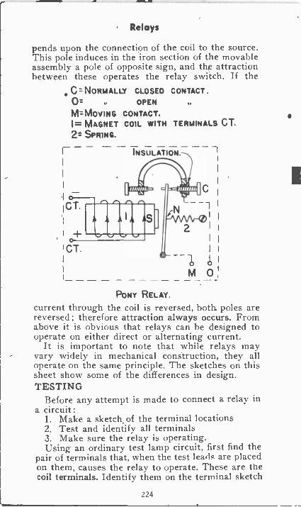
Relays
pends upon the connection of the coil to the source.This pole induces in the iron section of the movableassembly a pole of opposite sign, and dip attractionbetween these operates the relay switch. If the
C NORMALLY CLOSED CONTACT.0= OPEN
M=MOVING CONTACT.1= MAGNET COIL WITH TERMINALS CT.2= SPRING.
I
I CT.
!CT.
INSULATION. 1
IC
-
2 II
M 0
PONY RELAY.
current through the coil is reversed, both. poles arereversed ; therefore attraction always occurs. Fromabove it is obvious that relays can be designed tooperate on either direct or alternating current.
It is important to note that while relays mayvary widely in mechanical construction, they alloperate on the same principle. The sketches on thissheet show some of the differences in design.TESTING
Before any attempt is made to connect a relay ina circuit :
1. Make a sketch of the terminal locations2. Test and identify all terminals3. Make sure the relay is operating.Using an ordinary test lamp circuit, first find the
pair of terminals that, when the test leads are placedon them, causes the relay to operate. These are thecoil terminals. Identify them on the terminal sketch
224
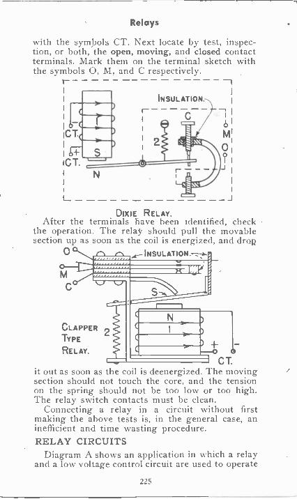
Relays
with the symbols CT. Next locate by test; inspec-tion, or both, the open, moving, and closed contactterminals. Mark them on the terminal sketch withthe symbols 0, M, and C respectively.
II
I IN SUL AT ION. ,I
)_._,
1
_4C I I
I
Egli I/
I
..
... / b I
'CT 4.11.11
II MrI
Ii 11.1 0
?1
I+ .
iI'CT. 0I N
..
--JDIXIE RELAY.
After the terminals have been identified, checkthe operation. The relay should pull the movablesection up as soon as the coil is energized, and drop
INSULATION. --*-0
M
CLAPPERTYPE
RELAY.4-
C T.it out as soon as the coil is deenergized. The movingsection should not touch the core, and the tensionon the spring should not be too low or too high.The relay switch contacts must be clean.
Connecting a relay in a circuit without firstmaking the above tests is, in the general case, aninefficient and time wasting procedure.RELAY CIRCUITS
Diagram A shows an application in which a relayand a low voltage control circuit are used to operate
225
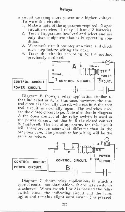
Relays
a circuit carrying more power at a higher voltage.To wire this circuit :1. Make a note of the apparatus required. 2 open
circuit switches ; 1 relay ; 1 lamp ; 2 batteries.2. Test all apparatus involved and select and use
only that equipment that is in operating con-dition.
3. Wire each circuit one step at a time, and checkeach step before wiring the next.
4. Trace the circuits according to the methodpreviously outlined.
CONTROL CIRCUIT.
POWER CIRCUIT.
A
CONTROL CIRCUIT.
POWER
CIRCUIT.hl
Diagram B shows a relay application similar tothat indicated in A. In this case, however, the con-trol circuit whereas in A the con--trol circuit is normally open. The switches usedare the closed circuit type. Note also that in diagramA the open contact of the relay switch is used inthe power circuit, but that in B the closed contactis employed. The list of apparatus for this circuitwill therefore be somewhat different than in theprevious case. The procedure for wiring will be thesame as before.
CONTROL CIRCUIT.
POWER CIRCUIT.
c0
POWERtd
CIRCUIT.
Diagram C shows relay applications in which atype of control not obtainable with ordinary switchesis achieved. When switch 1 or 2 is pressed the relayswitch closes the indicating circuit and the lamplights and remains alight until switch 3 is pressed,
226
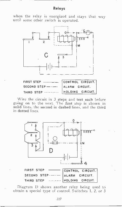
Relays
when the relay is energized and stays that wayuntil some other switch is operated.
FIRST STEP
SECOND STEP
THIRD STEP
CONTROL CIRCUIT.ALARM CIRCUIT.
HOLDING CIRCUIT.
Wire the circuit in 3 steps and test each beforegoing on to the next. The first step is shown insolid lines, the second in dashed lines, and the thirdin dotted lines.
FIRST STEP
SECOND STEP
THIRD STEP
CONTROL CIRCUIT.ALARM CIRCUIT.
HOLDING CIRCUIT.
Diagram D shows another relay being used toobtain a special type of control. Switches 1, 2, or 3
227
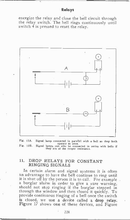
Relays
energize the relay and close the bell circuit throughthe relay switch. The bell rings continuously untilswitch 4 is pressed to reset the relay.
B
I I
0
0
Fig. 13A. Signal lamp connected in parallel with a bell so they bothoperate at once.
Fig. 13B. Signal lamps can also be connected in series with bells ifthey are of the nroper resistance.
11. DROP RELAYS FOR CONSTANTRINGING SIGNALS
In certain alarm and signal systems it is oftenan advantage to have the bell continue to ring untilit is shut off by the person it is to call. For examplea burglar alarm in order to give a sure warning,should not stop ringing if the burglar stepped inthrough the window and then closed it quickly. Toprovide continuous tinging of a bell once the switchis closed, we use a device called a drop relay.Figure 17 shows one of these devices, and Figure
228
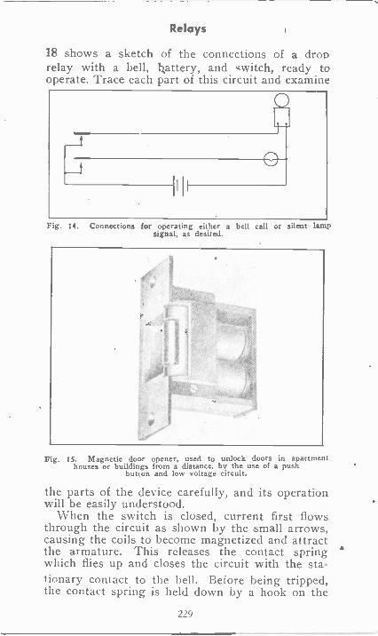
Relays
18 shows a sketch of the connections of a droprelay with a bell, battery, and switch, ready tooperate. Trace each part of this circuit and examine
Fig. 14. Connections for operating either a bell call or silent lampSignal, as desired.
Fig. 15. Magnetic door opener, used to unlock doors in apartmenthouses or buildings from a distance, by the use of a push
button and low voltage circuit.
the parts of the device carefully, and its operationwill be easily understood.
When the switch is closed, current first flowsthrough the circuit as shown by the small arrows,causing the coils to become magnetized and attractthe armature. This releases the contact springwhich flies up and closes the circuit with the sta-tionary contact to the bell. Before being tripped,the contact spring is held down by a hook on the
229
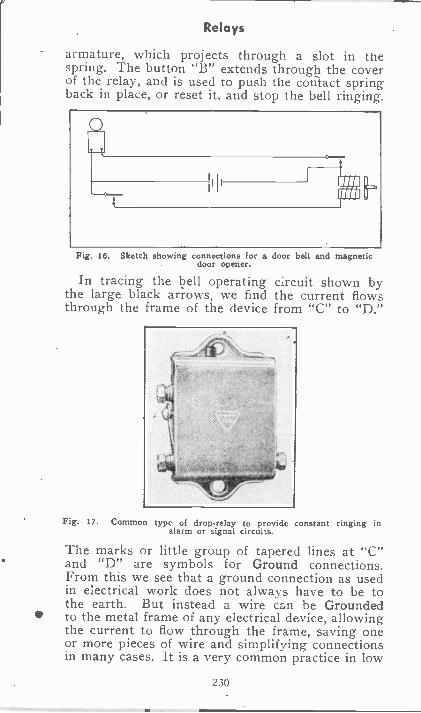
Relays
armature, which projects through a slot in thespring. The button "B" extends through the coverof the relay, and is used to push the contact springback in place, or reset it, and stop the bell ringing.
Fig. 16. Sketch showing connections for a door bell and magneticdoor opener.
In tracing the bell operating circuit shown bythe large black arrows, we find the current flowsthrough the frame of the device from "C" to "D."
Fig. 17. Common type of drop -relay to provide constant ringing inalarm or signal circuits.
The marks or little group of tapered lines at "C"and "D" are symbols for Ground connections.From this we see that a ground connection as usedin electrical work does not always have to be tothe earth. But instead a wire can be Groundedto the metal frame of any electrical de -vice, allowingthe current to flow through the frame, saving oneor more pieces of wire and simplifying connectionsin many cases. It is a very common practice in low
230
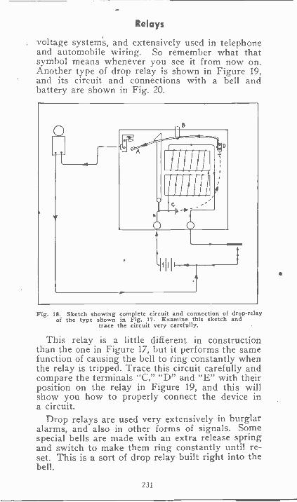
Relays
voltage systems, and extensively used in telephoneand automobile wiring. So remember what thatsymbol means whenever you see it from now on.Another type of drop relay is shown in Figure 19,and its circuit and connections with a bell andbattery are shown in Fig. 20.
Fig. 18. Sketch showing complete circuit and connection of drop -relayof the type shown in Fig. 17. Examine this sketch and
trace the circuit very carefully.
This relay is a little different in constructionthan the one in Figure 17, but it performs the samefunction of causing the bell to ring constantly whenthe relay is tripped. Trace this circuit carefully andcompare the terminals "C," "D" and "E" with theirposition on the relay in Figure 19, and this willshow you how to properly connect the device ina circuit.
Drop relays are used very extensively in burglaralarms, and also in other forms of signals. Somespecial bells are made with an extra release springand switch to make them ring constantly until re-set. This is a sort of drop relay built right into thebell.
231
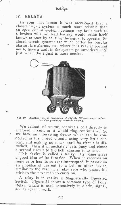
ReIchfs
12. RELAYSIn your last lesson it was mentioned that a
closed circuit system is much more reliable thanan open circuit system, because any fault such asa broken wire or dead battery would make itselfknown at once by causing the signal to operate. Soclosed circuit systems are much better for burglaralarms, fire alarms, etc., where it is very importantnot to have a fault in the system go unnoticed untiljust when the signal is most needed.
Fig. 19. Another type of drop -relay of slightly different construction,but also providing constant ringing.
We cannot, of course, connect a bell directly ina closed circuit, or it would ring continually. Sowe have an interesting device which can be con-nected in the closed circuit, using very little cur-rent, and making no noise until its circuit is dis-turbed. Then it immediately gets busy and closesa second circuit to the bell, causing it to ring.
This device is called a Relay. Its name givesa good idea of its function. When it receives animpulse or has its current interrupted, it passes onan impulse of current to a bell or other device,similar to the man in a relay race who passes hisstick to the next man to carry on.
A relay is in reality a Magnetically OperatedSwitch. Figure 21 shows a common type df PonyRelay, which is used extensively in alarm, signal,and telegraph work.
232
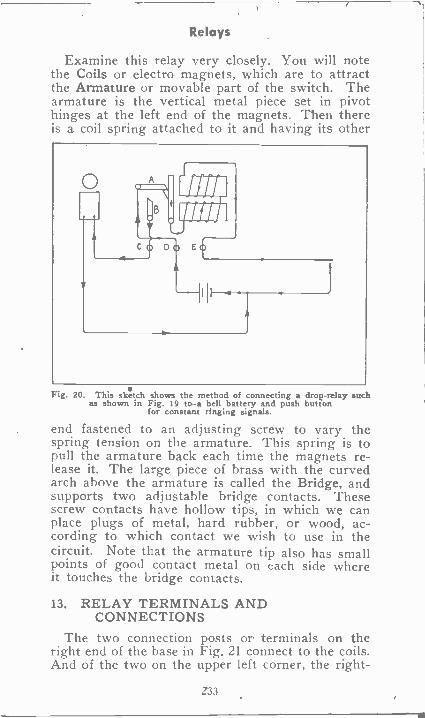
Relays
Examine this relay very closely. You will notethe Coils or electro magnets, which are to attractthe Armature or movable part of the switch. Thearmature is the vertical metal piece set in pivothinges at the left end of the magnets. Then thereis a coil spring attached to it and having its other
CO DO E0
Fig. 20. This sketch shows the method of connecting a drop -relay suchas shown in Fig. 19 to. -a bell battery and push button
for constant ringing signals.
end fastened to an adjusting screw to vary thespring tension on the armature. This spring is topull the armature back each time the magnets re-lease it. The large piece of brass with the curvedarch above the armature is called the Bridge, andsupports two adjustable bridge contacts. Thesescrew contacts have hollow tips, in which we canplace plugs of metal, hard rubber, or wood, ac-cording to which contact we wish to use in thecircuit. Note that the armature tip also has smallpoints of good contact metal on each side whereit touches the bridge contacts.
13. RELAY TERMINALS ANDCONNECTIONS
The two connection posts or terminals on theright end of the base in Fig. 21 connect to the coils.And of the two on the upper left corner, the right -
Z33
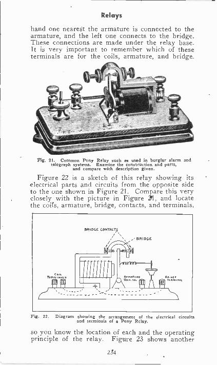
Relays
hand one nearest the armature is connected to thearmature, and the left one connects to the bridge.These connections are made under the relay base.It is very important to remember which of theseterminals are for the coils, armature, and bridge.
Fig. 21. Common Pony Relay such as used in burglar alarm andtelegraph systems. Examine the construction and parts,
and compare with description given.
Figure 22 is a sketch of this relay showing itselectrical parts and circuits from the opposite sideto the one shown in Figure 21. Compare this veryclosely with the picture in Figure 21, and locatethe coils, armature, bridge, contacts, and terminals,
Fig. 22. Diagram showing the arrangement of the electrical circuitsand terminals of a Pony Relay.
so you know the location of each and the operatingprinciple of the relay. Figure 23 shows another
234
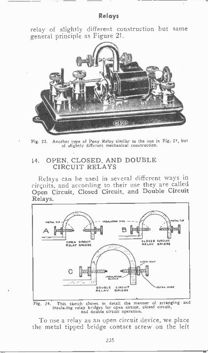
Relays
relay of slightly different construction but samegeneral principle as Figure 21.
Fig. 23. Another type of Pony Relay similar to the one in Fig. 21, butof slightly different mechanical construction.
14. OPEN, CLOSED, AND DOUBLECIRCUIT RELAYS
Relays can be used in several different ways incircuits, and according to their use they are calledOpen Circuit, Closed Circuit, and Double CircuitRelays.
PUTTY TIP - INJOLATINT NIN -- NUN. TIP
OPEN CIRCUIT CLO3ED CIRCUITRELAY !RIDGE RELAY ORIDSI
LOC. NUT
IN3ULATINIT
DOUBLE CIRCUIT TIMM WI.,RELAY DRIOCE
Fig. 24. This sketch shows in detail the manner of arranging andinsulating relay bridges for open circuit, closed circuit,
and double circuit operation.
To use a relay as an open circuit device, we placethe metal tipped bridge contact screw on the left
235
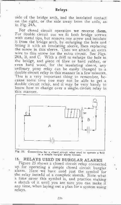
Relays
side of the bridge arch, and the insulated contacton the right, or the side away from the coils, asin Fig. 24A.
For closed circuit operation we reverse them.For double circuit use we fit both bridge screwswith metal tips, but remove one screw and insulateit from the bridge arch, by enlarging the hole andfitting it with an insulating sleeve, then replacingthe screw in this sleeve. Then we attach an extrawire to this screw for the extra circuit. See Figs.24A, B, and C. With a drill to enlarge the hole inthe bridge, and piece of fibre or hard rubber, oreven hard wood, for The insulating sleeve, anyordinary pony relay can be easily changed to adouble circuit relay in this mannerin a few minutes.This is a very important thing to remember, be-cause some time you may not be able to get adouble circuit relay, and it may be very handy toknow how to change over a single. circuit relay inthis manner.
Fig. 25. Connections for a closed circuit relay used to operate a 'bellin a simple burglar alarm system.
15. RELAYS USED IN BURGLAR ALARMSFigure 25 shows a closed circuit relay connected
up for operating a simple closed circuit burglaralarm. Here we have used just the symbol forthe relay instead of a complete sketch. Note whata time saver this symbol is, and practice makinga sketch of it until you are sure you can make itany time, when laying out a plan for a system usingrelays.
236
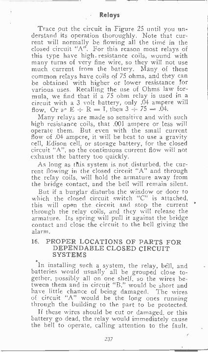
Relays
Trace out the circuit in Figure 25 until you un-derstand its operation thoroughly. Note that cur-rent will normally be flowing all the time in theclosed circuit "A". For this reason most relays ofthis type have high. resistance coils, wound withmany turns of very fine wire, so they will not usemuch current from the battery. Many of thesecommon relays have coils of 75 ohms, and they canbe obtained with higher or lower resistance forvarious uses. Recalling the use of Ohms law for-mula, we find that if a 75 ohm relay is used in acircuit with a 3 volt battery, only .04 ampere willflow. Or E R I, then 3 ÷ 75 - .04.
Many relays are made so sensitive and with suchhigh resistance coils, that .001 ampere or less willoperate them. But even with the small currentflow of .04 ampere, it will be best to use a gravitycell, Edison cell, or storage battery, for the closedcircuit "A", so the continuous current flow will notexhaust the battery too quickly.
As long as this system is not disturbed, the cur-rent flowing in the closed circuit "A" and throughthe relay coils, will hold the armature away fromthe bridge contact, and the bell will remain silent.
But if a burglar disturbs the window or door towhich the closed circuit switch "C" is attached,this will open the circuit and stop the currentthrough the relay coils, and they will release thearmature. Its spring will pull it against the bridgecontact and close the circuit to the bell giving thealarm.16. PROPER LOCATIONS OF PARTS FOR
DEPENDABLE CLOSED CIRCUITSYSTEMS
installing such a system, the relay, bell, andbatteries would usually all be grouped close to-gether, possibly all on one shelf, so the wires be-tween them and in circuit "B," would be short andhave little chance of being damaged. The wiresof circuit "A" would be the long ones runningthrough the building to the part to be protected.
If these wires should be cut or damaged, or thisbattery go dead, the relay would immediately causethe bell to operate, calling attention to the fault.
237
Relays
While with an open circuit system the wire couldbe cut, or the battery dead, and the system outof order, without any one knowing it, and thus failto operate when needed the most.
The battery in circuit "B" is not likely to godead so often, as there is very seldom any currentrequired from it. But it should be tested occa-sionally to make sure it is in good condition. Anyimportant alarm system should be tested daily, orevery evening, before being switched on for thenight.
In Figure 25, in the relay symbol, we only showthe one bridge contact which is in use.
When we desire to operate a bell or signalsounder at a considerable distance, an open circuitrelay can be used to good advantage to save send-ing the heavier current required by the bell overthe long line.
If we were to send the heavy current over thelong line, it would cause considerable voltage dropand we would have to use larger, more expensivewires, or higher voltage supply. But the relay cur-rent being very small can be sent over the linemore economically, and the relay will act as aswitch at the far end of the line, to close a Localcircuit to the bell. See Figure 26.
This circuit uses an open circuit relay, and thebridge contact on the side opposite to the one usedin Figure 25. This method of using a relay tooperate on a feeble impulse of current, and closea circuit to a larger device requiring more current,is one of their most common applications.
17. USE OF RELAYS IN TELEGRAPHSYSTEMS. GROUND CIRCUITS
Figure 27 shows two relays at opposite ends ofa line, and operating Sounders in local circuits, ina simple telegraph system. The primary circuitincludes two line batteries, two key switches, andtwo high resistance relay coils. The secondary cir-cuits each consist of a local battery and sounder,and include the relay armature and bridge contactsas their switches. You will note that only one linewire is used in the primary circuit, and the earthis used for the other side of the circuit, by ground -
238
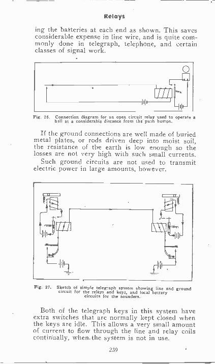
Relays
ing the batteries at each end as shown. This savesconsiderable expense in line wire, and is quite com-monly done in telegraph, telephone, and certainclasses of signal work.
O
I'll
Fig. 26. Connection diagram for an open circuit relay used to operate ab.1.11 at a considerable distance from the push button.
If the ground connections are well made of buriedmetal plates, or rods driven deep into moist soil,the resistance of the earth is low enough so thelosses are not very high with such small currents.
Such ground circuits are not used to transmitelectric power in large amounts, however.
Fig. 27. Sketch of simple teleg-aph system showing line and groundcircuit for the relays and keys, and local battery
circuits for the sounders.
Both of the telegraph keys in this system haveextra switches that are normally kept closed whenthe keys are idle. This allows a very small amountof current to flow through the line and relay coilscontinually, when.the system is not in use.
239
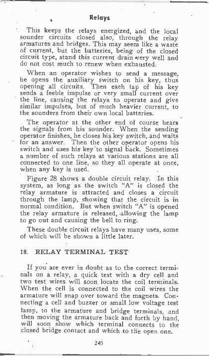
Relays
This keeps the relays energized, and the localsounder circuits closed also, through the relayarmatures and bridges. This may seem like a wasteof current, but the batteries, being of the closedcircuit type, stand this current drain .very well anddo not cost much to renew when exhausted.
When an operator wishes to send a message,he opens the auxiliary switch on his key, thusopening all circuits. Then each tap of his keysends a feeble impulse or very small current overthe line, causing the relays to operate and givesimilar impulses, but of much heavier current, tothe sounders from their own local batteries.
The operator at the other end of course hearsthe signals from his sounder. When the sendingoperator finishes, he closes his key switch, and waitsfor an answer. Then the other operator opens hisswitch and uses his key 'to signal back. Sometimesa number of such relays at various stations are allconnected to one line, so they all operate at once,when any key is used.
Figure 28 shows a double circuit relay. In thissystem, as long as the switch "A" is closed therelay armature is attracted and closes a circuitthrough the lamp, showing that the circuit is innormal condition. But when switch "A" is openedthe relay armature is released, .allowing the lampto go out and causing the bell to ring.
These double circuit relays have many uses, someof which will be shown a little later.
18. RELAY TERMINAL TEST
If you are ever in doubt as to the correct termi-nals on a relay, a quick test with a dry cell andtwo test wires will soon locate the coil terminals.When the cell is connected to the coil wires thearmature will snap over toward the magnets. Con-necting a cell and buzzer or small low voltage testlamp, to the armature and bridge terminals, andthen moving the armature back and forth by hand,will soon show which terminal connects to theclosed bridge contact and which to the open one.
240
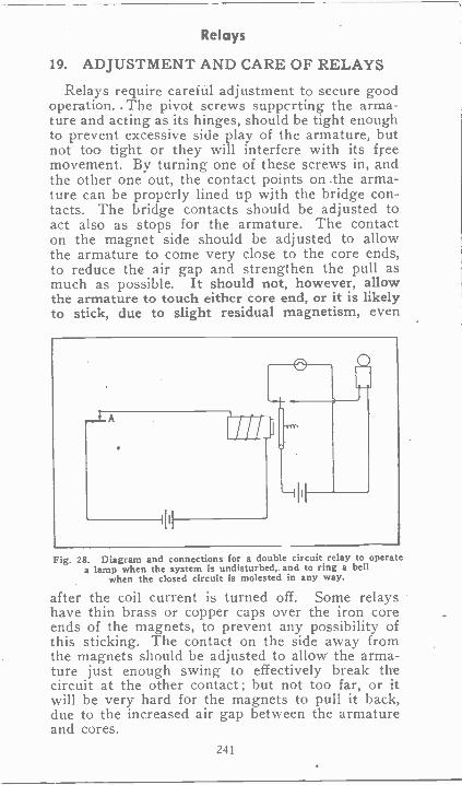
Relays
19. ADJUSTMENT AND CARE OF RELAYS
Relays require careful adjustment to secure goodoperation. . The pivot screws supperting the arma-ture and acting as its hinges, should be tight enoughto prevent excessive side play of the armature, butnot too tight or they will interfere with its freemovement. By turning one of these screws in, andthe other one out, the contact points on .the arma-ture can be properly lined up with the bridge con-tacts. The bridge contacts should be adjusted toact also as stops for the armature. The contacton the magnet side should be adjusted to allowthe armature to come very close to the core ends,to reduce the air gap and strengthen the pull asmuch as possible. It should not, however, allowthe armature to touch either core end, or it is likelyto stick, due to slight residual magnetism, even
Fig. 28. Diagram and connections for a double circuit relay to operatea lamp when the system is undisturbed, and to ring a bell
when the closed circuit is molested in any way.
after the coil current is turned off. Some relayshave thin brass or copper caps over the iron coreends of the magnets, to prevent any possibility ofthis sticking. The contact on the side away fromthe magnets should be adjusted to allow' the arma-ture just enough swing to effectively break thecircuit at the other contact ; but not too far, or itwill be very hard for the magnets to pull it back,due to the increased air gap between the armatureand cores.
241
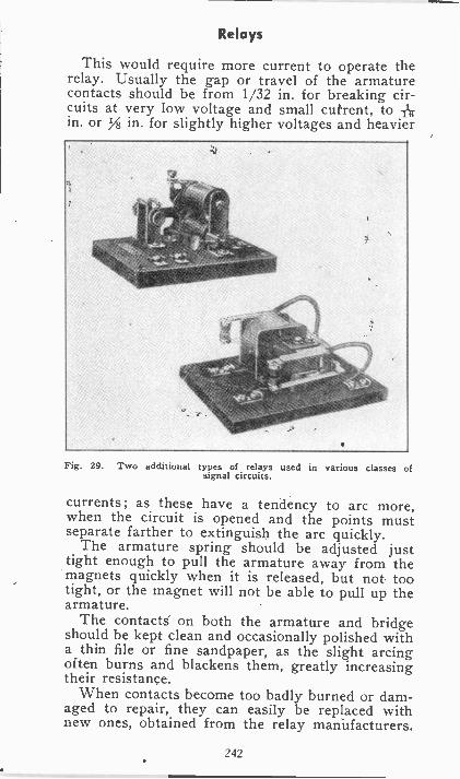
Relays
This would require more current to operate therelay. Usually the gap or travel of the armaturecontacts should be from 1/32 in. for breaking cir-cuits at very low voltage and small current, to -Ar,in. or in. for slightly higher voltages and heavier
Fig. 29. Two additional types of relays used in various classes ofsignal circuits.
currents; as these have a tendency to arc more,when the circuit is opened and the points mustseparate farther to extinguish the arc quickly.
The armature spring should be adjusted justtight enough to pull the armature away from themagnets quickly when it is released, but not tootight, or the magnet will not be able to pull up thearmature.
The contacts on both the armature and bridgeshould be kept clean and occasionally polished witha thin file or fine sandpaper, as the slight arcingoften burns and blackens them, greatly increasingtheir resistance.
When contacts become too badly burned or dam-aged to repair, they can easily be replaced withnew ones, obtained from the relay manufacturers.
242
Relays
Dust and dirt should be kept off from all parts,and all terminal nuts should be kept tight. Coresof magnets should be kept tight on keeper barsupport.
Occasionally, but not often, a relay coil may be-come open, grounded, or shorted, or completelyburned out. Simple tests as given in lesson num-ber six on electro-magnets will locate any suchfault. In addition to these pony relays, there arenumerous other types used in telephones, railwaysignals, power plants, etc. Some of these differ inmechanical construction and shape, from the onesjust described, but their general purpose and prin-ciple are very much the same. So if you have agood understanding of the relays in this section andalways remember that any relay is simply a mag-netically operated switch, you should be able toeasily understand most any type.
Millions of relays are in use in plants throughoutthe country and every trained electrical man shouldbe able to intelligently connect, test and maintainthese important devices as they are used to controlmany electrical systems and machines.
243
EXAMINATION QUESTIONS
1. What is the difference between a single strokebell and a vibrating bell?
2. What is a relay?
3. For what purpose is a Drop 42. elay used?
t. Draw a diagram showing a double circuit re-lay connected so as to make a lamp burn whenthe circuit is undisturbed, andso that it willcause a bell to ring when the relay coil circuitis molested.
5. How are relays classed according to their use?
6. What name has been given the movable part ofa relay?
7. What name has been given tothe curved archabove the movable part of the relay?
8. Will a series vibrating bell operate on alternat-ing current?
9. Which gives a softer tone a buzzer or a bell?
10. What device would you select to give a silentsignal?
244
ANNUNCIATORS
SIGNAL SYSTEMS
From our study of the electric signals we nowknow there are three important and necessaryfactors in the successful operation of any type ofsignal system. These are :
1. Source of current supply or power.2. Some means' of controlling this current sup-
ply or power.3. Some type of equipment for converting the
electrical energy into a signal.The power, or current supply, can be obtained
either from a battery or from the line which sup-plies the regular power for lights, motors, etc.
The control may be one of any of several typesof switches, relays, etc.
The necessary equipment for converting the en-ergy into an audible signal may be any device suchas a bell, buzzer, or horn ; or it may be a devicethat converts the electrical energy into a visiblesignal, such as light from a lamp.
In addition to using a visible electric light sig-nal, we have another very important and widelyused piece of equipment for furnishing visible sig-nals, which has the advantage of indicating justwhere the signals originate or come from.
Stich a visible signal device is known as an AN-NUNCIATOR and is widely used in such placesas hotels, offices, elevators, on trains, etc.
When we are in a large building and wish tomake use of the elevator to transport us from onefloor to another, we simply push a button switchat the elevator entrance, and the signal immedi-ately flashes to the operator in the elevator. Thissignal then registers on an annunciator whichshows the- operator that someone desires to use theelevator and it also shows the operator on whichfloor you are located.
245
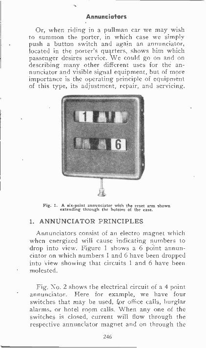
Annunciators
Or, when riding in a pullman car we may wishto summon the porter, in which case we simplypush a button switch and again an annunciator,located in the porter's quarters, shows him whichpassenger desires service. We could go on and ondescribing many other different uses for the an-nunciator and visible signal equipment, but of moreimportance is the operating principle of equipmentof this type, its adjustment, repair, and servicing.
Fig. 1. A six -point annunciator with the reset arm shownextending through the bottom of the case.
1. ANNUNCIATOR PRINCIPLES
Annunciators consist of an electro magnet whichwhen energized will cause indicating numbers todrop into view. Figure 1 shows a 6 point annun-ciator on which numbers 1 and 6 have been droppedinto view showing that circuits 1 and 6 have beenmolested.
Fig. No. 2 shows the electrical circuit of a 4 pointannunciator. Here for example, we have fourswitches that may be used, fpr office calls, burglaralarms. or hotel room calls. When any one of theswitches is closed, current will flow through therespective annunciator magnet and on through the
246
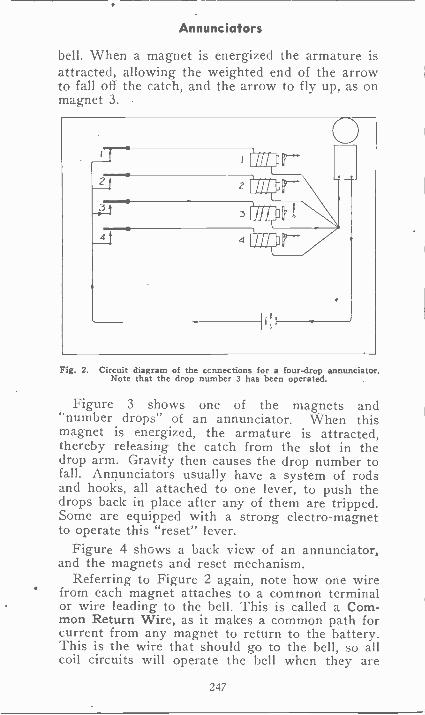
Annunciators
bell. When a magnet is energized the armature isattracted, allowing the weighted end of the arrowto fall off the catch, and the arrow to fly up, as onmagnet 3.
Fig. 2. Circuit diagram of the ccnnections for a four -drop annunciator.Note that the drop number 3 has been operated.
Figure 3 shows one of the magnets and"number drops" of an annunciator. When thismagnet is energized, the armature is attracted,thereby releasing the catch from the slot in thedrop arm. Gravity then causes the drop number tofall. Annunciators usually have a system of rodsand hooks, all attached to one lever, to push thedrops back in place after any of them are tripped.Some are equipped with a strong electro-magnetto operate this "reset" lever.
Figure 4 shows a back view of an annunciator,and the magnets and reset mechanism.
Referring to Figure 2 again, note how one wirefrom each magnet attaches to a common terminalor wire leading to the bell. This is called a Com-mon Return Wire, as it makes a common path forcurrent from any magnet to return to the battery.This is the wire that should go to the bell, so allcoil circuits will operate the bell when they are
247
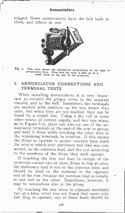
Annunciators
tripped. Some annunciators have the bell built inthem, and others do not.
Fig. 3. This view shows the mechanical construction of one type ofannunciator drop. Note how the drop is held up by asmall hook on the end of the armature.
2. ANNUNCIATOR CONNECTIONS ANDTERMINAL TESTS
When installing annunciators it is very impor-tant to connect the proper wires to the separatecircuits, and to the bell. Sometimes the terminalsare marked with numbers on the box where theyenter, but when they are not marked, they can befound by a simple test. Using a dry cell or someother source of current supply, and two test wires,as in Figure 5-A, place one wire on one of the an-nunciator terminals at the end of the row or group,and hold it there while touching the other wire tothe remaining terminals in rotation. If this causesthe drops to operate in proper rotation then markthe wire to which your stationary test lead was con-nected, as the common lead, and the rest accordingto the numbers of the drops they each operate.
If touching the free test lead to certain of theterminals causes two or more drops to trip at once,the stationary lead is not on the common wire, andshould be tried on the terminal at the oppositeend of the row, because the common lead is usuallyat one end or the other. Sometimes, however, itmay be somewhere else in the group.
By touching the test wires to adjacent terminalstwo at a time, when two are found that cause onlyone drop to operate, one of these leads should be
248
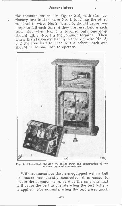
Annunciators
the common return. In Figure 5-B, with the sta-tionary test lead on wire No. 1, touching the othertest lead to wires No. 2, 4, and 5, should cause twodrops to fall each time, if they are reset before eachtest. But when No. 3 is touched only one dropshould fall, as No. 3 is the common terminal. Thenwhen the stationary lead is placed on wire No. 3,and the free lead touched to the others, each oneshould cause one drop to operate.
Fig. 4. Photograph showing the inside parts and construction of twocommon types of annunciators.
With annunciators that are equipped with a bellor buzzer permanently connected, it is easier tolocate the common wire, as it is the only one thatwill cause the bell to operate when the test batteryis applied. For example, when the test wires touch
249
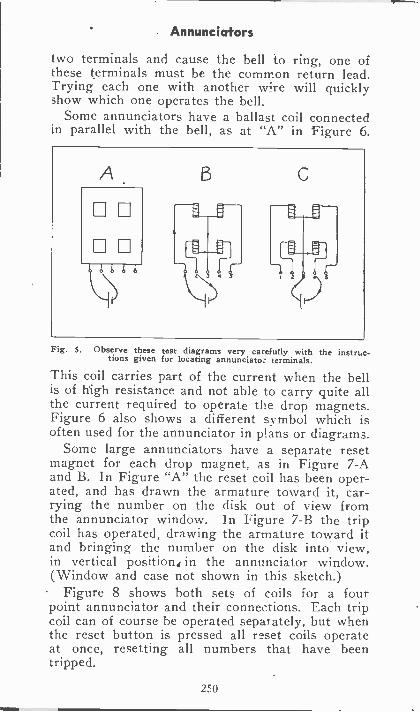
Annunciators
two terminals and cause the bell to ring, one ofthese terminals must be the common return lead.Trying each one with another wire will quicklyshow which one operates the bell.
Some annunciators have a ballast coil connectedin parallel with the bell, as at "A" in Figure 6.
Fig. 5. Observe these test diagrams very carefully with thetions given for locating annunciator terminals.
This coil carries part of the current when the bellis of high resistance and not able to carry quite allthe current required to operate the drop magnets.Figure 6 also shows a different symbol which isoften used for the annunciator in plans or diagrams.
Some large annunciators have a separate resetmagnet for each drop magnet, as in Figure 7-Aand B. In Figure "A" the reset coil has been oper-ated, and has drawn the armature toward it, car-rying the number on the disk out of view fromthe annunciator window. In Figure 7-B the tripcoil has operated, drawing the armature toward itand bringing the number on the disk into view,in vertical positions in the annunciator window.(Window and case not shown in this sketch.)
Figure 8 shows both sets of coils for a fourpoint annunciator and their connections. Each tripcoil can of course be operated separately, but whenthe reset button is pressed all reset coils operateat once, resetting all numbers that have beentripped.
250
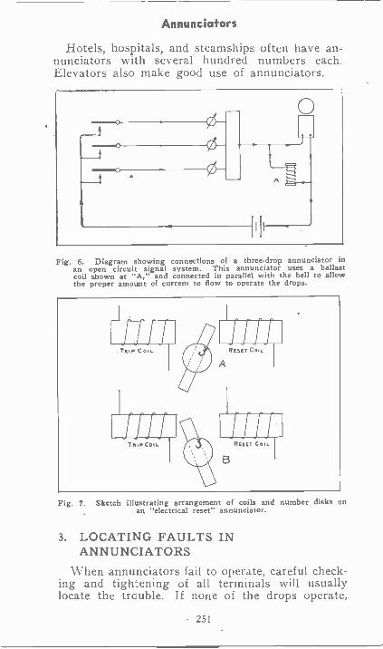
Annunciators
Hotels, hospitals, and steamships often have an-nunciators with several hundred numbers each.Elevators also make good use of annunciators.
I
ig. 6. Diagram showing connections of a three -drop annunciator inan open circuit signal system. This annunciator uses a ballastcoil shown at "A," and connected in parallel with the bell to allowthe proper amount of current to flow to operate the drops.
F
Fig. 7. Sketch illustrating arrangement of coils and number disks onan "electrical reset" annunciator.
3. LOCATING FAULTS INANNUNCIATORS
When annunciators fail to operate, careful check-ing and tightening of all terminals will usuallylocate the trouble. If none of the drops operate,
251
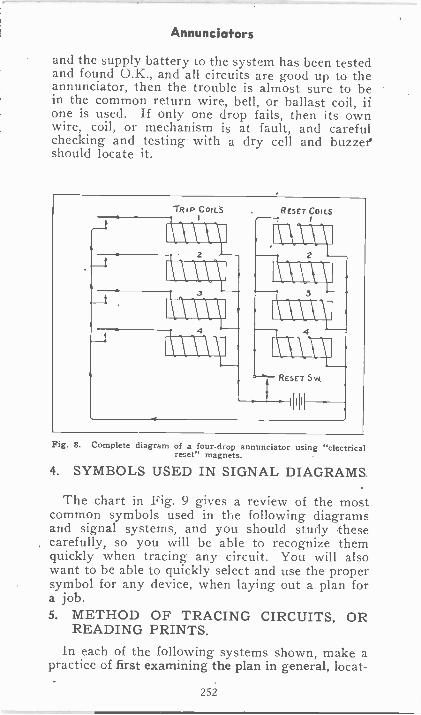
Annunciators
and the supply battery to the system has been testedand found U.K., and all circuits are good up to theannunciator, then the trouble is almost sure to bein the common return wire, bell, or ballast coil, ifone is used. If only one drop fails, then its ownwire, coil, or mechanism is at fault, and carefulchecking and testing with a dry cell and buzzer'should locate it.
TRIP COILS
3
RESET COILS
\AA\
IYX41\.\4
\\RCS"- SW.
(HI
Fig. 8. Complete diagram of a four -drop annunciator using "electricalreset" magnets.
4. SYMBOLS USED IN SIGNAL DIAGRAMS.
The chart in Fig. 9 gives a review of the mostcommon symbols used in the following diagramsand signal systems, and you should study thesecarefully, so you will be able to recognize themquickly when tracing any circuit. You will alsowant to be able to quickly select and use the propersymbol for any device, when laying out a plan fora job.5. METHOD OF TRACING CIRCUITS, OR
READING PRINTS.In each of the following systems shown, make a
practice of first examining the plan in general, locat-
2.52
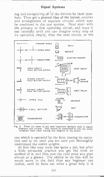
Signal Systems
ing and recognizing all of the devices by their sym-bols. Then get a general idea of the layout, numberand arrangement of separate circuits which maybe combined in the one system. Next start withthe, primary or first operating circuit, and trace itout carefully until you can imagine every step ofits operation clearly, then the next circuit, or the
STRAIGHT WIRES
----- OR -I- 00/NED WIRES
OR CROSSED WIRES
OPEN CIRCUITPUSH BUTTON SWITCH
CLOSED CIRCUITPUSH BUTTON SWITCH
OL DOUBLE CIRCUITPUSH BUTTON SWITCH
JINGLE CELL
.3 CELL BATTERY
]III TRANSFORM ER
0 BELL
BUZZER
.711 ri ELECTRO-MAGNETI
.1'
L.
DROP RELAY
DOOROPENER
PONY RELAY
JOUN DER
KEY
ANNUNCIATOR
Fig. 9. These are some of the most important symbols used in signaldiagrams and circuits. They should be memorized so you can easilyrecognize them when tracing any diagram in the future.
one which is operated by the first, tracing its opera-tion and so on until you are sure you thoroughlyunderstand the entire system.
At first this may seem like quite a job, but aftera little persistent practice you get the trick ormethod of it, and then you can read most any planalmost at a glance. The ability to do this will beworth more in the field than any beginner canrealize, until he finds out what a great help it is
253
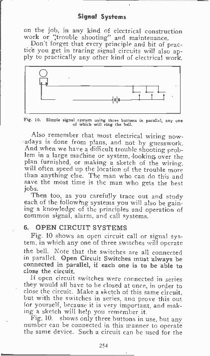
Signal Systems
on the job, in any kind of electrical constructionwork or ;trouble shooting" and maintenance.
Don't forget that every principle and bit of prac-tice you get in tracing signal circuits will also ap-ply to practically any other kind of .electrical work.
0L_
t t t
Fig. 10. Simple signal system using three buttons in parallel, any oneof which will ring the bell.
Also remember that most electrical wiring now-adays is done from plans, and not by guesswork.And when we have a difficult trouble shooting prob-lem in a large madhine or system, .lookin* over theplan furnished, or making a sketch of the wiring,will often speed up the location of the trouble morethan anything else. The man who can do this andsave the most time is the man who gets the bestjobs.
Then too, as you carefully trace out and studyeach of the followtng systems you will also be gain-ing a knowledge of the principles and operation ofcommon signal, alarm, and call systems.
6. OPEN CIRCUIT SYSTEMSFig. 10 shows an open circuit call or signal sys-
tem, in which any one of three switches will operatethe bell. Note that the switches are all connectedin parallel. Open Circuit Switches must always beconnected in parallel, if each one is to be able toclose the circuit.
If open circuit switches were connected in seriesthey would all have to be closed at once, in order toclose the circuit. Make a sketch of this same circuit,but with the switches in series, ana prove this outfor yourself, because it is very important, and mak-ing a sketch will help you remember it.
Fig. 10. shows only three buttons in use, but anynumber can be connected in this manner to operatethe same device. Such a circuit can be used for the
254
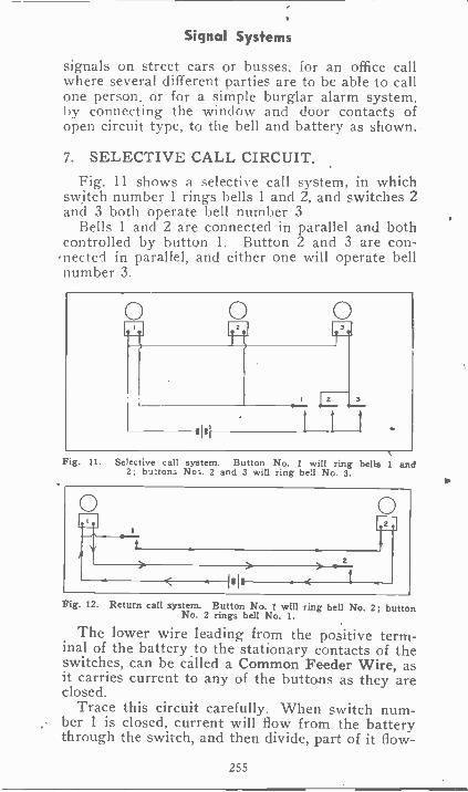
Signal Systems
signals on street cars or busses, for an office callwhere several different parties are to be able to callone person, or for a simple burglar alarm system,by connecting the window and door contacts ofopen circuit type, to the bell and battery as shown.
7. SELECTIVE CALL CIRCUIT.Fig. 11 shows a selective call system, in which
switch number 1 rings bells 1 and 2, and switches 2and 3 both operate bell number 3
Bells 1 and 2 are connected in parallel and bothcontrolled by button 1. Button 2 and 3 are con-ected in parallel, and either one will operate hell
number 3.
Fig. 11. Selective call system. Button No. I will ring bells 1 and2; button; No;. 2 and 3 will ring bell No. 3.
Fig. 12. Return call system. Button No. 1 will ring bell No. 2; buttonNo. 2 rings bell No. 1.
The lower wire leading from the positive term-inal of the battery to the stationary contacts of theswitches, can be called a Common Feeder Wire, asit carries current to any of the buttons as they areclosed.
Trace this circuit carefully. When switch num-ber 1 is closed, current will flow from the batterythrough the switch, and then divide, part of it flow -
255
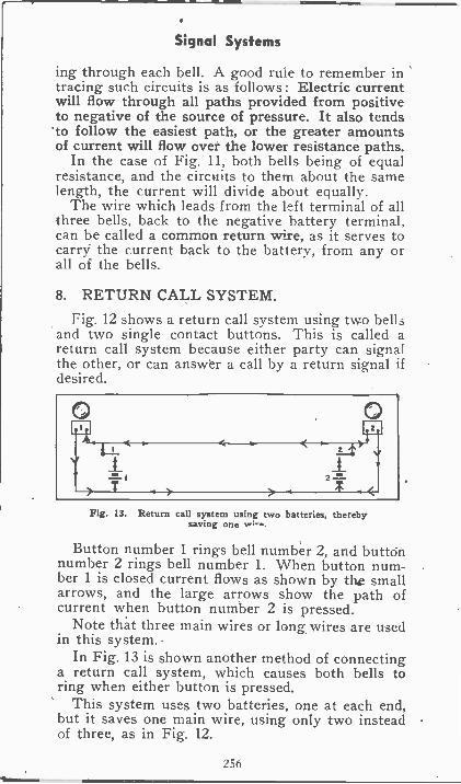
Signal Systems
ing through each bell. A good rule to remember intracing such circuits is as follows : Electric currentwill flow through all paths provided from positiveto negative of the source of pressure. It also tendsto follow the easiest path, or the greater amountsof current will flow over the lower resistance paths.
In the case of Fig. 11, both bells being of equalresistance, and the circuits to them about the samelength, the current will divide about equally.
The wire which leads from the left terminal of allthree bells, back to the negative battery terminal,can be called a common return wire, as it serves tocarry the current back to the battery, from any orall of the bells.
8. RETURN CALL SYSTEM.
Fig. 12 shows a return call system using two bellsand two single contact buttons. This is called areturn call system because either party can signalthe other, or can answer a call by a return signal ifdesired.
0. 1-111< 1...t>
2
Fig. 13. Return call system using two batteries, therebysaving one w;-.
Button number 1 rings bell number 2, and buttonnumber 2 rings bell number 1. When button num-ber 1 is closed current flows as shown by the smallarrows, and the large arrows show the path ofcurrent when button number 2 is pressed.
Note that three main wires or long wires are usedin this system..
In Fig. 13 is shown another method of connectinga return call system, which causes both bells toring when either button is pressed.
This system uses two batteries, one at each end,but it saves one main wire, using only two insteadof three, as in Fig. 12.
256
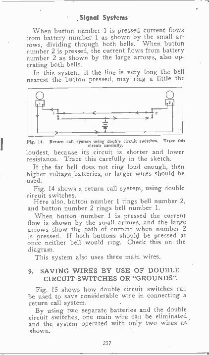
Signal Systems
When button number 1 is pressed current flowsfrom battery number 1 as shown by the small ar-rows, dividing through both bells. When buttonnumber 2 is pressed, the current flows from batterynumber 2 as shown by the large arrows, also op-erating both bells.
In this system, if the line is very long the bellnearest the button pressed, may ring a little the
Fig. 14. Return call system using double circuit switches. Trace thiscircuit carefully.
loudest, because its circuit is shorter and lowerresistance. Trace this carefully in the sketch.
If the far bell does not ring loud enough, thenhigher voltage batteries, or larger wires should beused.
Fig. 14 shows a return call system, using doublecircuit switches.
Here also, button number 1 rings bell number 2.and button number 2 rings bell number 1.
When button number 1 is pressed the currentflow is shown by the small arrows, and the largearrows show the path of current when number 2is pressed. If both buttons shoulcol be pressed atonce neither bell would ring. Check this on thediagram.
This system also uses three main wires.
9. SAVING WIRES BY USE OF DOUBLECIRCUIT SWITCHES OR "GROUNDS".
Fig. 15 shows how double circuit switches canbe used to save considerable wire in connecting areturn call system.
By using two separate batteries and the doublecircuit switches, one main wire can be eliminatedand the system operated with only two wires asshown.
257
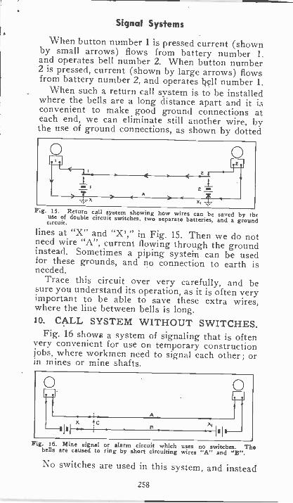
Signal Systems
When button number 1 is pressed current (shownby small arrows) flows from battery number 1.and operates bell number 2. When button number2 is pressed, current (shown by large arrows) flowsfrom battery number 2, and operates 17111 number 1.
When such a return call system is to be installedwhere the bells are a long distance apart and it isconvenient to make good ground connections ateach end, we can eliminate still another wire, bythe use of ground connections, as shown by dotted
Fig. 15. Return call system showing how wires can be saved by theuse of double circuit switches, two separate batteries, and a groundcircuit.
lines at "X" and "X'," in Fig. 15. Then we do notneed wire "A", current flowing through the groundinstead. Sometimes a piping systein can be usedfor these grounds, and no connection to earth isneeded.
Trace this circuit over very carefully, and besure you understand its operation, as it is often veryimportant to, be able to save these extra wires,where the line between bells is long.10. CALL SYSTEM WITHOUT SWITCHES.
Fig. 16 shows a system of signaling that is oftenvery convenient for use on temporary constructionjobs, where workmen need to signal each other; orin mines or mine shafts.
Fig. 16. Mine signal or alarm circuit which uses no switches. Thebells are caused to ring by short circuiting wires "A" and "B".
No switches are used in this system, and instead
258
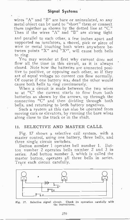
Signal Systems
wires "A" and "B" are bare or uninsulated, so anymetal object can be used to "short" them or connectthem together as shown by the dotted line at "C."Then if the wires "A" and "B" are strung tightand parallel to each other, a few inches apart andsupported on insulators, a shovel, pick or piece ofwire or metal touching both wires anywhere be-tween points "X" and "XI", will cause both bellsto ring.
You may wonder at first why current does notflow all the time in this circuit, as it is alwaysclosed. Note how the batteries are connected posi-tive to positive, or opposing each other, so if theyart of equal voltage no current can flow normally.Of course if one battery Was dead the other wouldcause both bells to ring continuously.
When a circuit is made between the two wiresas at "C" the current starts to flow from bothbatteries as shown by the arrows, up through theconnection "C" and then dividing through bothbells, and returning to both battery negatives.
Such a system as this can also be operated frommoving cars or elevators, by running the bare wiresalong close to the track or in the shaft.
11. SELECTIVE AND MASTER CALLS.Fig. 17 shows a selective call system, with a
master control, using one battery, three bells, andthree single circuit switches.
Button number 1 operates bell number 1. But-ton number 2 operates bells number 2 and 3 inseries. And button number 3, which is called themaster button, operates all three bells in series.Trace each circuit carefully.
r"7 3z
0113 I
Fig. 17. Selective signal circuit. Check its operation carefully withthe instructions.
259
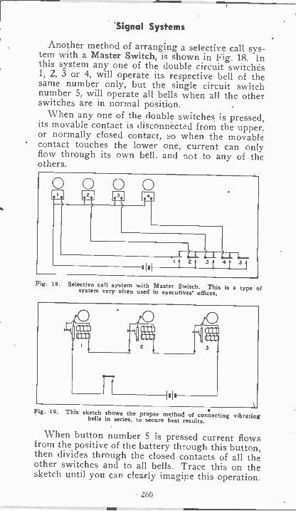
Signal Systems
Another method of arranging a selective call sys-tem with a Master Switch, is shown in Fig. 18. Inthis system any one of the double circuit switches1, 2, 3 or 4, will operate its respective bell of thesame number only, but the single circuit switchnumber 5, will operate all bells when all the otherswitches are in normal position.
When any one of the double switches is pressed,its movable contact is disconnected from the upper.or normally closed contact, so when the movablecontact touches the lower one, current can onlyflow through its own bell. and not to any of theothers.
Fig. 18. Selective call system with Master Switch. This is a type ofsystem very often used in executives' offices.
Fig. 19. This sketch shows the proper method of connecting vibratingbells in series, to secure best results.
When button number 5 is pressed current flowsfrom the positive of the battery through this button,then divides through the closed contacts of all theother switches and to all bells. Trace this on thesketch until you can clearly imagine this operation.
260
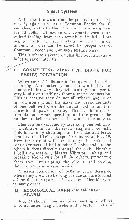
Signal Systems
Note how the wire from the positive of the bat-tery is again used as a Common Feeder for allswitches, and also the common return wire usedfor all bells. Of course one separate wire is re-quired feeding from each switch to its bell, if weare to operate them separately at times, but a greatamount of wire can be saved by proper use ofCommon Feeder and Common Return wires.
This is where a sketch or plan laid out in advancehelps to save materials.
12. CONNECTING VIBRATING BELLS FORSERIES OPERATION.
When several bells are to be operated in seriesas in Fig. 19, or other systems for which they areconnected this way, they will usually not operatevery loudly or steadily without a special connection.This is because they do not all vibrate evenly orin synchronism, and the make and break contactsof one bell will open the circuit just as anothercloses for its power impulse. This results in ratherirregular and weak operation, and the greater thenumber of bells in series, the worse it usually is.
This can be overcome by arranging one bell onlyas a vibrator, and all, the rest as single stroke bells.This is done by shunting out the make and breakcontacts of all bells except the one, as in Fig. 19.Here the current will flow through the make andbreak contacts of bell number 1 only, and on theothers it flows directly through the coils. Number1 bell then acts as a Master Vibrator, making andbreaking the circuit for all the others, preventingthem from interrupting the circuit, and forcingthem to operate in synchronism.
A series connection of bells is often desirablewhere they are all to be rung at once and are locateda long distance apart, as it saves considerable wirein many cases.13. ECONOMICAL BARN OR GARAGE
ALARM.
Fig. 20 shows a method of connecting a bell asa combination single stroke and vibrator, and ob-
261
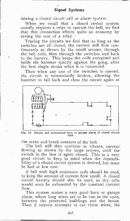
Signal Systems
taining a closed' circuit call or alarm system.When we recall that a closed circuit system
usually requires a relay to operate the bell, we findthat this connection effects quite an economy bysaving the cost of a relay.
Tracing the circuits we find that as long as theswitches are all closed, the current will flow con-tinuously as shown by the small arrows, throughthe bell coils, then through the switches and backto the battery. This keeps the coils energized andholds the hammer quietly against the gong, afterthe first single stroke when it is connected.
Then when any one of the switches is opened,the circuit is momentarily broken, allowing thehammer to fall back and close the circuit again at
Tg. 20. Simple and economical barn or garage alarm of closed circuittype.
the make and break contacts of the bell.The bell will then continue to vibrate, current
flowing as shown by the large arrows, until theswitch in the line is again closed. This is a verygood circuit to keep in mind when the dependa-bility of a closed circuit system is desired, but mustbe had at low cost
A bell with high resistance coils should be used,to keep the amount of current flow small. A closedcircuit battery should also be used, as dry cellswould soon be exhausted by the constant currentflow.
This system makes a very good barn or garagealarm, where long wires are to be run in the open,between the protected buildings and the house.Then if anyone attempts to cut these wires, the
262
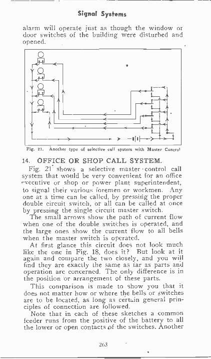
Signal Systems
alarm will operate just as though the window ordoor switches of the building were disturbed andopened.
Fig. 21. Another type of selective call system with Master Control
14. OFFICE OR SHOP CALL SYSTEM.Fig. 21- shows a selective master- control call
system that would be very convenient for an officePxecutive or shop or power plant superintendent,to signal their various foremen or workmen. Anyone at a time can be called, by pressing the properdouble circuit switoh, of all can be called at onceby pressing the single circuit master switch.
The small arrows show the path of current flowwhen one of the double switches is operated, andthe large ones show the current flow to all bellswhen the master switch is operated.
At first glance this circuit does not look muchlike the one in Fig. 18, does it? But look at itagain and compare the two closely, and you willfind they are exactly the same as tar as parts andoperation are concerned. The only difference is inthe position 'or arrangement of these parts.
This comparison is made to show you that itdoes not matter how or where the bells or switchesare to be located, as long as certain general prin-ciples of connection are followed.
Note that in each of these sketches a commonfeeder runs from the positive of the battery to allthe lower or open contacts of the switches. Another
263
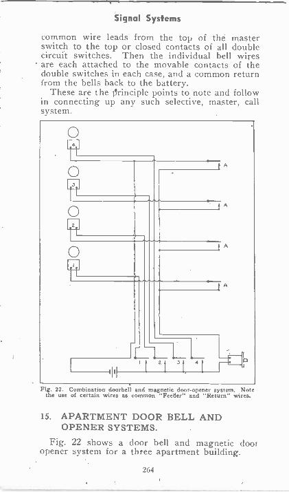
Signal Systems
common wire leads from the top of the masterswitch to the top or closed contacts of all doublecircuit switches. Then the individual bell wiresare each attached to the movable contacts of thedouble switches in each case, and a common returnfrom the bells back to the battery.
These are the ilrinciple points to note and followin connecting up any such selective, master, callsystem.
0
ft
c --L_ L L ii., it 211 41 1
A
A
A
Fig. 22. Combination doorbell and magnetic door -opener system. Notethe use of certain wires as common "Feeder" and "Return" wires.
15. APARTMENT DOOR BELL ANDOPENER SYSTEMS.
Fig. 22 shows a door bell and magnetic (lootopener system for a three apartment building.
264
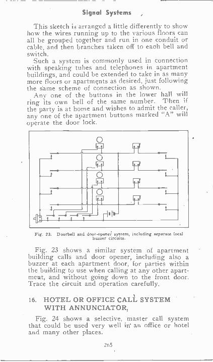
Signal Systems
This sketch is arranged a little differently to showhow the wires running up to the various floors canall be grouped together and run in one conduit orcable, and then branches taken off to each bell andswitch.
Such a system is commonly used in connectionwith speaking tubes and telephones in apartmentbuildings, and could be extended to take in as manymore floors or apartments as desired, just followingthe same scheme of connection as shown.
Any one of the buttons in the lower hall willring its own bell of the same number. Then ifthe party is at home and wishes to admit the caller,any one of the apartment buttons marked "A" willoperate the door lock.
Fig. 23. Doorbell and door -opener system, including separate localbuzzer circuits.
Fig. 23 shows a similar system of apartmentbuilding calls and door opener, including also abuzzer at each apartment door, for parties withinthe building to use when calling at any other apart-ment, and without going down to the front door.Trace the circuit and operation carefully,
16. HOTEL OR OFFICE CALL SYSTEMWITH ANNUNCIATOR;
Fig. 24 shows a selective, master call systemthat could be used very well in' an office or hoteland many other places.
265
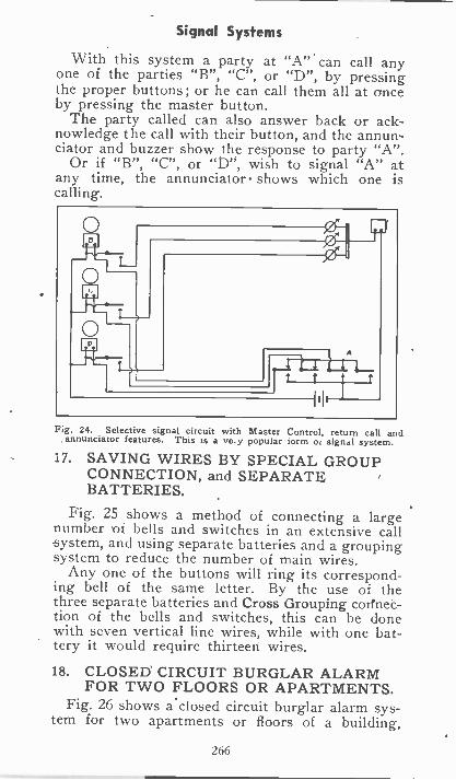
Signal Systems
With this system a party at "A" can call anyone of the parties "B", "C", or "D", by pressingthe proper buttons; or he can call them all at onceby pressing the master button.
The party called can also answer back or ack-nowledge the call with their button, and the annun-ciator and buzzer show the response to party "A".
Or if "B", "C", or "D", wish to signal "A" atany time, the annunciator shows which one iscalling.
Fig. 24. Selective signal circuit with Master Control, return call andannunciator features. This is a ve.y popular tom of signal system.
17. SAVING WIRES BY SPECIAL GROUPCONNECTION, and SEPARATEBATTERIES.
Fig. 25 shows a method of connecting a largenumber of bells and switches in an extensive callsystem, and using separate batteries and a groupingsystem to reduce the number of main wires.
Any one of the buttons will ring its correspond-ing bell of the same letter. By the use of thethree separate batteries and Cross Grouping corfnec-tion of the bells and switches, this can be donewith seven vertical line wires, while with one bat-tery it would require thirteen wires.
18. CLOSED CIRCUIT BURGLAR ALARMFOR TWO FLOORS OR APARTMENTS.
Fig. 26 shows aclosed circuit burglar alarm sys-tem for two apartments or floors of a building,
266
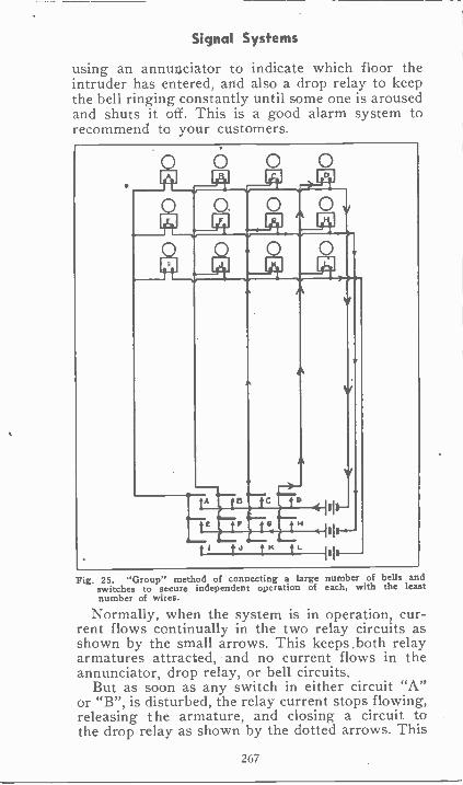
Signal Systems
using an annul ciator to indicate which floor theintruder has entered, artd also a drop relay to keepthe bell ringing constantly until some one is arousedand shuts it off. This is a good alarm system torecommend to your customers.
Fig. 25. "Group" method of connecting a large number of bells andswitches to secure independent operation of each, with the leastnumber of wires.
Normally, when the system is in operation, cur-rent flows continually in the two relay circuits asshown by the small arrows. This keeps .both relayarmatures attracted, and no current flows in theannunciator, drop relay, or bell circuits.
But as soon as any switch in either circuit "A"or "B", is disturbed, the relay current stops flowing,releasing the armature, and closing a circuit tothe drop relay as shown by the dotted arrows. This
267
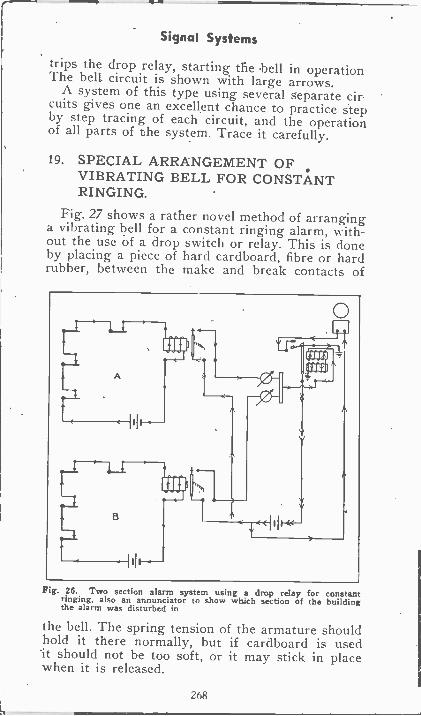
Signal Systems
trips the drop relay, starting the bell in operationThe bell circuit is shown with large arrows.
A system of this type using several separate cir.cuits gives one an excellent chance to practice stepby step tracing of each circuit, and the operationof all parts of the system. Trace it carefully.
19. SPECIAL ARRANGEMENT OFVIBRATING BELL FOR CONSTANTRINGING.
Fig. 27 shows a rather novel method of arranginga vibrating bell for a constant ringing alarm, with-out the use of a drop switch or relay. This is doneby placing a piece of hard cardboard, fibre or hardrubber, between the make and break contacts of
Fig. 26. Two section alarm system using a drop relay for constantringing, also an annunciator to show which section of the buildingthe alarm was disturbed in
the bell. The spring tension of the armature shouldhold it there normally, but if cardboard is usedIt should not be too soft, or it may stick in placewhen it is released.
268
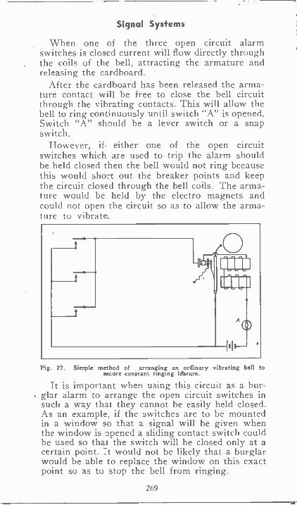
Signal Systems
When one of the three open circuit alarmswitches is closed current will flow directly throughthe coils of the bell, attracting the armature andreleasing the cardboard.
After the cardboard has been released the arma-ture contact will be free to close the bell circuitthrough the vibrating contacts. This will allow thebell to ring continuously until switch "A" is opened.Switch "A" should be a lever switch or a snapswitch.
However, if. either one of the open circuitswitches which are used to trip the alarm shouldbe held closed then the bell would not ring becausethis would short out the breaker points and keepthe circuit closed through the bell coils. The arma-ture would be held by the electro magnets andcould not open the circuit so as to allow the arma-ture to vibrate.
Fig. 27. Simple method of arranging an ordinary vibrating bell tosecure constant ringing feature.
It is important when using this circuit as a bur-. glar alarm to arrange the open circuit switches in
such a way that they cannot be easily held closed.As an example, if the switches are to be mountedin a window so that a signal will be given whenthe window is opened a sliding contact switch couldbe used so that the switch will be closed only at acertain point. It would not be likely that a burglarwould be able to replace the window on this exactpoint so as to stop the bell from ringing.
269
Signal Systems
This system of course does not give the positiveprotection of a closed circuit system, or of oneusing a relay, but is very good for an emergencyjob, or one where the cost must be kept very low.
Now let us advise you to review the signal andalarm systems shown in this lesson and see howmany places you can think of where some of thesesystems would save time or protect property foryour friends and neighbors.
Then recommend the proper system and go afterthe job of installing it for experience and profit.
EXAMINATION QUESTIONS
1-Show the symbol used for each of the follow-ing: (a) bell, (b) buzzer, (c) double circuit switch,(d) open circuit switch.
2-What do we mean by the term Master Vi-brator when two or more bells are connected inseries?
3-For what purpose are annunciators used?
4-Are closed circuit switches connected in seriesor parallel with each other?
5-Are open circuit switches connected in seriesor parallel with each other?
6-Make a diagram showing how a bell may beconnected so as to operate without a relay in aclosed circuit alarm system.
7-Draw a sketch showing how a bell may beconnected for constant ringing without the use ofa relay or a drop switch.
8-What advantage does a closed circuit alarmhave over an open circuit alarm?
9-Copy Fig. 11, and trace the circuits throughwhich current would flow if switch No 1 is closed.Mark the circuit with little arrows.
10-Copy Fig. 17 and trace the circuit throughwhich current would flow when switch No. 2 isclosed.
270
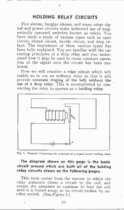
HOLDING RELAY CIRCUITSFire alarms, burglar alarms, and many other sig-
nal and power circuits make unlimited use of mag-netically operated switches known as relays. Youhave made a study of various types such as opencircuit, closed circuit, double circuit, and drop re-lays. The importance of these various types hasbeen fully explained. You are familiar with the op-erating principles of a drop relay and you under-stand how it may be used to cause constant opera-tion of the signal once the circuit has been mo-lested.
Now we will consider a relay circuit which willenable us to use an ordinary relay so that it willprovide constant ringing of the bell, without theuse of a drop relay. This is accomplished by con-necting the relay to operate as a holding relay.
Fig. 1. Diagram illustrating the principle of a closed circuit holding relay.
The diagram shown on this page is the basiccircuit around which are built all of the holdingrelay circuits shown on the following' pages.
This term comes from the manner in which therelay armature closes a circuit to the coil, andcauses the armature to continue to feed the coiluntil it is forced away, or its circuit broken by an-other switch. (See. Figure 1.)
271
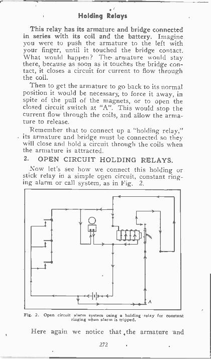
Holding Relays
This relay has its armature and bridge connectedin series with its coil and the battery. Imagineyou were to push the armature to the left withyour finger, until it touched the bridge contact.What would happen? The. armature would staythere, because as soon as it touches the bridge con-tact, it closes a circuit for current to flow throughthe coil.
Then to get the armature to go back to its normalposition it would be necessary, to force it away, inspite of the pull of the magnets, or to open theclosed circuit switch at "A". This would stop thecurrent flow through the coils, and allow the arma-ture to release.
Remember that to connect up a "holding relay,"its armature and bridge must be connected so theywill close and hold a circuit through the coils whenthe armature is attracted.2. OPEN CIRCUIT HOLDING RELAYS.
Now let's see how we connect this holding orstick relay in a simple open circuit, constant ring-ing alarm or call system, as in Fig. 2.
Fig. 2. Open circuit alarm system using a holding relay for constantringing when alarm is tripped.
Here again we notice that ,the armature and
272
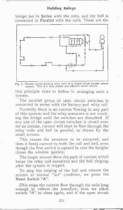
Holding Relays
bridge are in Series with the coils, and the bell isconnected in Parallel with the coils. These are the
Fig. 3. Double circuit holding relay used in a closed circuit burglar alarmsystem. This is a very simple and efficient alarm circuit.
two principle rules to follow in arranging such asystem.
The parallel group of open circuit switches isconnected in series with the battery and relay coil.
Normally there is no current flowing in any partof this system, and the relay armature is not touch-ing the bridge until the switches are disturbed. Ifany one of the open circuit switches is closed evenfor an instant, current will start to flow through therelay coils and bell in parallel, as shown by thesmall arrows.
This causes the armature to be attracted, andthen it feeds current to both the coil and bell, eventhough the first switch is opened in case the burglarcloses the window quickly.
The larger arrows show the path of current whichkeeps the relay coil energized and the bell ringing,after the system is tripped.
To stop the ringing of the bell and restore thesystem to normal "set" condition, we press theReset Switch "A".
.This stops the current flow through the coils longenough to release the armature ; then we allowswitch "A" to close again, and if the open circuit
273
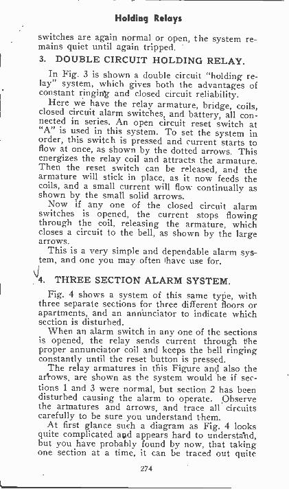
Holding Relays
switches are again normal or open, the system re-mains quiet until again tripped.3. DOUBLE CIRCUIT HOLDING RELAY.
In Fig. 3 is shown a double circuit "holding re-lay" system, which gives both the advantages ofconstant ringing and closed circuit reliability.
Here we have the relay armature, bridge, coils,closed circuit alarm switches, and battery, all con-nected in series. An open circuit reset switch at"A" is used in this system. To set the system inorder, this switch is pressed and current starts toflow at once, as shown by the dotted arrows. Thisenergizes the relay coil and attracts the armature.Then the reset switch can be released, and thearmature will stick in place, as it now feeds thecoils, and a small current will flow continually asshown by the small solid arrows.
Now if any one of the closed circuit alarmswitches is opened, the current stops flowingthrough the coil, releasing the armature, whichcloses a circuit to the bell, as shown by the largearrows.
This is a very simple and dependable alarm sys-tem, and one you may often have use for.
4. THREE SECTION ALARM SYSTEM.Fig. 4 shows a system of this same type, with
three separate sections for three different floors orapartments, and an annunciator to indicate whichsection is disturbed.
When an alarm switch in any one of the sectionsis opened, the relay sends current through theproper annunciator coil and keeps the bell ringingconstantly until the reset button is pressed.
The relay armatures in this Figure and also thearrows, are shown as the system would be if sec-tions 1 and 3 were normal, but section 2 has beendisturbed causing the alarm to operate. Observethe armatures and arrows, and trace all circuitscarefully to be sure you understand them.
At first glance such a diagram as Fig. 4 looksquite complicated agd appears hard to understalid,but you have probably found by now, that takingone section at a time, it can be traced out quite
274
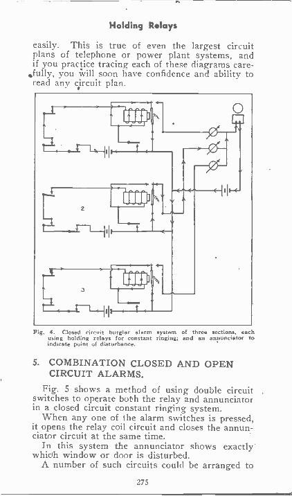
Holding Relays
easily. This is true of even the largest circuitplans of telephone or power plant systems, andif you practice tracing each of these diagrams care-fully, you will soon have confidence and ability toread any circuit plan.
-
I,
III
III
4-
1(*4-'".--4-11 11 -4-
Fig. 4. Closed circuit burglar alarm system of three sections, eachusing holding relays for constant ringing; and an annunciator toindicate point of disturbance.
5. COMBINATION CLOSED AND OPENCIRCUIT ALARMS.
Fig. 5 shows a method of using double circuitswitches to operate both the relay and annunciatorin a closed circuit constant ringing system.
When any one of the alarm switches is pressed,it opens the relay coil circuit and closes the annun-ciator circuit at the same time.
In this system the annunciator shows exactlywhioh window or door is disturbed.
A number of such circuits could be arranged to
275
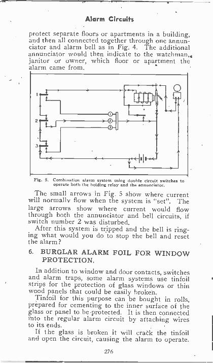
Alarm Circuits
protect separate floors or apartments in a building,and then all connected together through one annun-ciator and alarm bell as in Fig. 4. The additionalannunciator would then indicate to the watchman,janitor or owner, which floor or apartment thealarm came from.
0
0El
Fig. 5. Combination alarm system using double circuit switches tooperate both the holding relay and the annunciator.
The small arrows in Fig. 5 show where currentwill normally flow when the system is "set". Thelarge arrows show where current would flowthrough both the annunciator and bell circuits, ifswitch number 2 was disturbed.
After this system is tripped and the bell is ring-ing what would you do to stop the bell and resetthe alarm?6. BURGLAR ALARM FOIL FOR WINDOW
PROTECTION.
In addition to window and door contacts, switchesand alarm traps, some alarm systems use tinfoilstrips for the protection of glass windows or thinwood panels that could be easily broken.
Tinfoil for this purpose can be bought in rolls,prepared for cementing to the inner surface of theglass or panel to be protected. It is then connectedinto the regular alarm circuit by attaching wiresto its ends.
If the glass is broken it will crank the tinfoiland open the circuit, causing the alarm to operate.
276
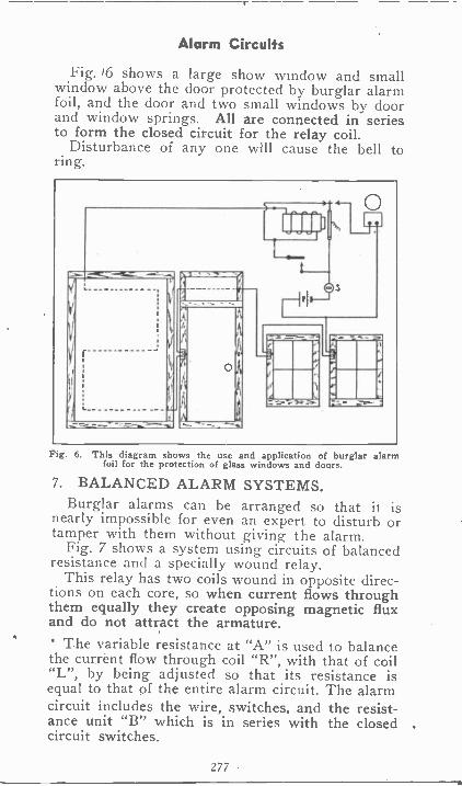
Alarm Circuits
Fig. '6 shows a large show window and smallwindow above the door protected by burglar alarmfoil, and the door and two small windows by doorand window springs. All are connected in seriesto form the closed circuit for the relay coil.
Disturbance of any one will cause the bell toring.
Fig. 6. This diagram shows the use and application of burglar alarmfoil for the protection of glass windows and doors.
7. BALANCED ALARM SYSTEMS.Burglar alarms can be arranged so that it is
nearly impossible for even an expert to disturb ortamper with them without giving the alarm.
Fig. 7 shows a system using circuits of balancedresistance and a specially wound relay.
This relay has two coils wound in opposite direc-tions on each core, so when current flows throughthem equally they create opposing magnetic fluxand do not attract the armature. The variable resistance at "A" is used to balancethe current flow through coil "R", with that of coil"L", by being adjusted so that its resistance isequal to that of the entire alarm circuit. The alarmcircuit includes the wire, switches, and the resist-ance unit "B" which is in series with the closed .circuit switches.
277
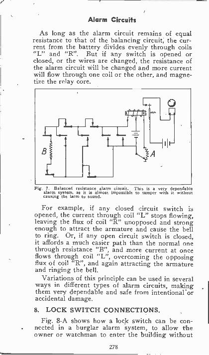
Alarm Circuits
As long as the alarm circuit remains of equalresistance to that of the balancing circuit, the cur-rent from the battery divides evenly through coils"L" and "R". But if any switch is opened orclosed, or the wires are changed, the resistance ofthe alarm circuit will be changed and more currentwill flow through one coil or the other, and magne-tize the relay core.
Fig. 7. Balanced resistance alarm circuit. This is a very dependablealarm system, as it is almost impossible to tamper with it withoutcausing the larm to sound.
For example, if any closed zircuit switch isopened, the current through coil "L" stops flowing,leaving the flux of coil "R" unopposed and strongenough to attract the armature and cause the bellto ring. Or, if any open circuit switch is closed,it affords a much easier path than the normal onethrough resistance "B", and more current at onceflows through coil "L", overcoming the opposingflux of coil "R", and again attracting the armatureand ringing the bell.
Variations of this principle can be used in severalways in different types of alarm circuits, makingthem very dependable and safe from intentional oraccidental damage.
8. LOCK SWITCH CONNECTIONS.Fig. 8-A shows how a lock switch can be con-
. nected in a burglar alarm system, to allow theowner or watchman to enter the building without
278
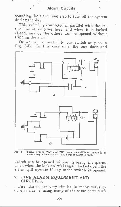
Alarm Circuits
sounding the alarm, and also to turn off the systemduring the day.
This switch is connected in parallel with the en-tire line of switches here, and when it is lockedclosed, any of the others can be opened withouttripping the alarm.
Or we can connect it to one switch only as inFig. 8-B. In this case only the one door and
Fig. 8. These circuits "A" and "B" show two different methods ofconnecting a lock switch to a burglar alarm circuit.
switch can be opened without tripping the alarm.Then when the lock switch is again locked open, thealarm will operate if any other switch is opened.
9. FIRE ALARM EQUIPMENT ANDCIRCUITS.
Fire alarms are very similar in many ways toburglar alarms, using many of the same parts such
279
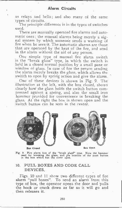
Alarm Circuits
as relays and bells ; and also many of the sametypes of circuits.
The principle difference is in the types of switchesused.
There are manually operated fire alarms and auto-matic ones ; the manual alarms being merely a sig-nal system by which someone sends a warning offire when he sees it. The automatic alarms are thosethat are operated by the heat of the fire, and sendin the alarm without the aid of any person.
One simple type of manual fire alarm switchis the "break glass" type, in which the switch isheld in a closed normal position by a small pane orwindow of glass. In case of fire the person sendingthe alarm merely breaks the glass, which allows theswitch to open by spring action and give the alarm.
One of these devices is shown in Fig. 9. Theillustration at the left, with the box closed, showsclearly hovel the glass holds the switch button com-pressed against a spring, and also the small ironhammer provided for convenience in breaking theglass. At the right the box is shown open and theswitch button can be seen in the center.
Box Closed Box Open
Fig. 9. Fire alarm box of the "break glasi" type. Note the hammerused for breaking the glass, and &he location of the push buttonin the box which has the cover open.
10. PULL BOXES AND CODE CALLDEVICES.
Figs. 10 and 11 show two different types of firealarm "pull boxes". To send an alarm from thistype of box, the operator opens the door and pullsthe hook or crank down as far as it will go andthen releases it.
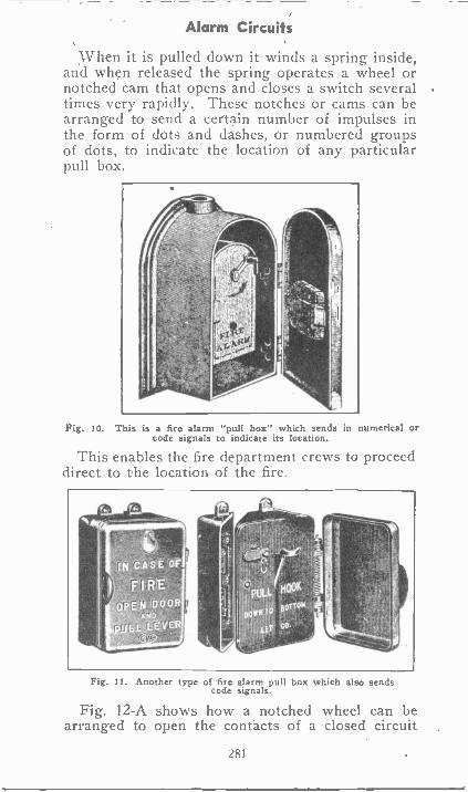
Alarm Circuits
When it is pulled down it winds a spring inside,and when released the spring operates a wheel ornotched cam that opens and closes a switch severaltimes very rapidly. These notches or cams can bearranged to send a certain number ,of impulses inthe form of dots and dashes, or numbered groupsof dots, to indicate the location of any particularpull box.
Fig. 10. This is a fire alarm "pull box" which sends in numerical orcode signals to indicate its location.
This enables the fire department crews to proceeddirect to the location of the fire.
IN CASE OF
F I RE
OPEN DOOR
Fig. 11. Another type of fire alarm pull box which also sendscode signals.
Fig. 12-A shows how a notched wheel can bearranged to open the contacts of a closed circuit
281
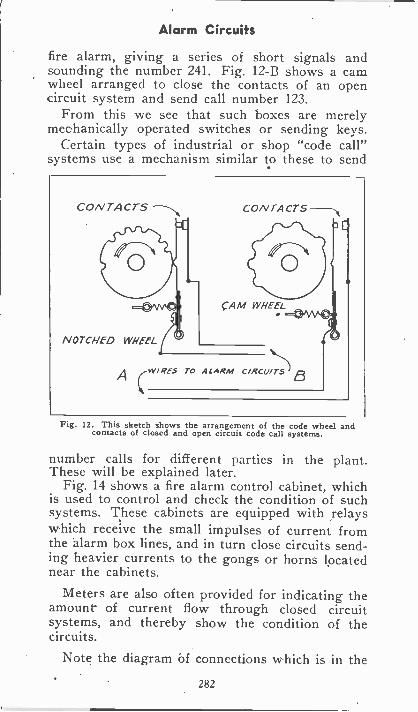
Alarm Circuits
fire alarm, giving a series of short signals andsounding the number 241. Fig. 12-B shows a camwheel arranged to close the contacts of an opencircuit system and send call number 123.
From this we see that such boxes are merelymechanically operated switches or sending keys.
Certain types of industrial or shop "code call"systems use a mechanism similar to these to send
Fig. 12. This sketch shows the arrangement of the code wheel andcontacts of closed and open circuit code call systems.
number calls for different parties in the plant.These will be explained later.
Fig. 14 shows a fire alarm control cabinet, whichis used to control and check the condition of suchsystems. These cabinets are equipped with relayswhich receive the small impulses of current fromthe alarm box lines, and in turn close circuits send-ing heavier currents to the gongs or horns locatednear the cabinets.
Meters are also often provided for indicating theamount of current flow through closed circuitsystems, and thereby show the condition of thecircuits.
Note the diagram of connections which is in the
282
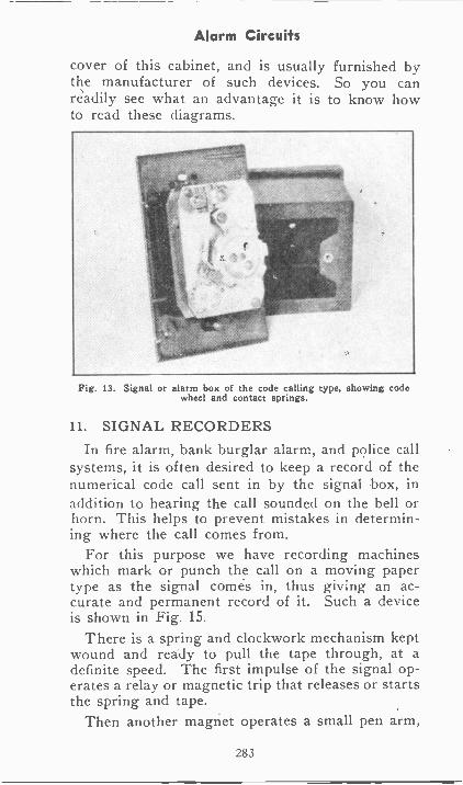
Alarm Circuits
cover of this cabinet, and is usually furnished bythe manufacturer of such devices. So you canreadily see what an advantage it is to know howto read these diagrams.
Fig. 13. Signal or alarm box of the code calling type, showing codewheel and contact springs.
11. SIGNAL RECORDERSIn fire alarm, bank burglar alarm, and police call
systems, it is often desired to keep a record of thenumerical code call sent in by the signal box, inaddition to hearing the call sounded on the bell orhorn. This helps to prevent mistakes in determin-ing where the call comes from.
For this purpose we have recording machineswhich mark or punch the call on a moving papertype as the signal comes in, thus giving an ac-curate and permanent record of it. Such a deviceis shown in Fig. 15.
There is a spring and clockwork mechanism keptwound and ready to pull the tape through, at adefinite speed. The first impulse of the signal op-erates a relay or magnetic trip that releases or startsthe spring and tape.
Then another magnet operates a small pen arm,
283
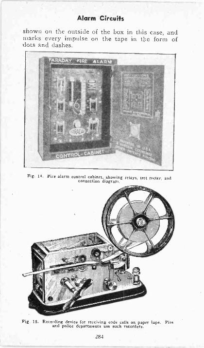
Alarm Circuifs
shown on the outside of the box in this case, andmarks every impulse on the tape in the form ofcots and dashes.
Fig. 14. Fire alarm control cabinet, showing relays, test meter, andconnection diagram.
Fig. 15. Recording device for receiving code calls on paper tape. Fireand police departments use such recorders.
284
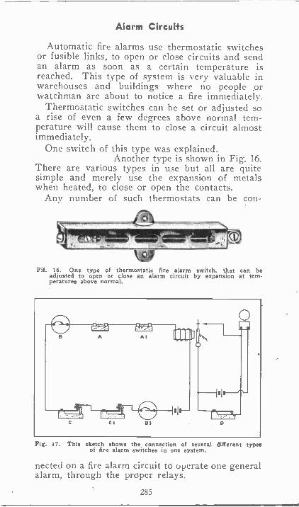
Alarm Circuits
Automatic fire alarms use thermostatic switchesor fusible links, to open or close circuits and sendan alarm as soon as a certain temperature isreached. This type of system is very valuable inwarehouses and buildings- where no people orwatchman are about to notice a fire immediately.
Thermostatic switches can be set or adjusted soa rise of even a few degrees above normal tem-perature will cause them to close a circuit almostimmediately.
One switch of this type was explained.Another type is shown in Fig. 16.
There are various types in use but all are quitesimple and merely use the expansion of metalswhen heated, to close or open the contacts.
Any number of such thermostats can be con -
kdoFil. 16. One type of thermostatic fire alarm switch, that can be
adjusted to open or close an alarm circuit by expansion at tern-peratures above normal.
Fig. 17. This sketch shows the connection of several different typesof fire alarm switches in one system.
nected on a fire alarm circuit to operate one generalalarm, through the proper relays.
285
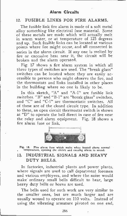
Alarm Circuits
12. FUSIBLE LINKS FOR FIRE ALARMS.The fusible link fire alarm is made of a soft metal
alloy something like electrical fuse material. Someof these metals are made which will actually meltin warm water, or at temperature of 125 degreesand up. Such fusible links can be located at variouspoints where fire might occur, and all connected inseries in the alarm circuit. If any one is melted byfire or excessive heat near it, the circuit will bebroken and the alarm operated.
Fig. 17 shows a fire alarm system in which allthree types of switches are used. The "break glass"switches can be located where they are easily ac-cessible to persons who might observe the fire, andthe thermostats and links installed in other placesin the building where no one is likely to be.
In this sketch, "A" and "A-1" are fusible linkswitches. "B" and "B-1" are "break glass" switches,and "C" and "C-1" are thermostatic switches. Allof these are of the closed circuit type. In additionto these, an open circuit thermostat switch is shownat "D" to operate the bell direct in case of fire nearthe relay and alarm equipment. Fig. 18 shows afire alarm fuse or link.
Fig. 18. Fire alarm fuse which melts when heated above normaltemperature, opening the circuit and causing alarm to sound.
13. INDUSTRIAL SIGNALS AND HEAVYDUTY BELLS.
In factories, industrial plants and power plants,where signals are used to call department foremenand various employees, and where the noise wouldmake ordinary small bells difficult to hear, largeheavy duty bells or horns are used.
The bells used for such work are very similar tothe smaller ones, but are much larger and areusually wound to operate on 110 volts. Instead ofusing the vibrating armature pivoted on one end,
286
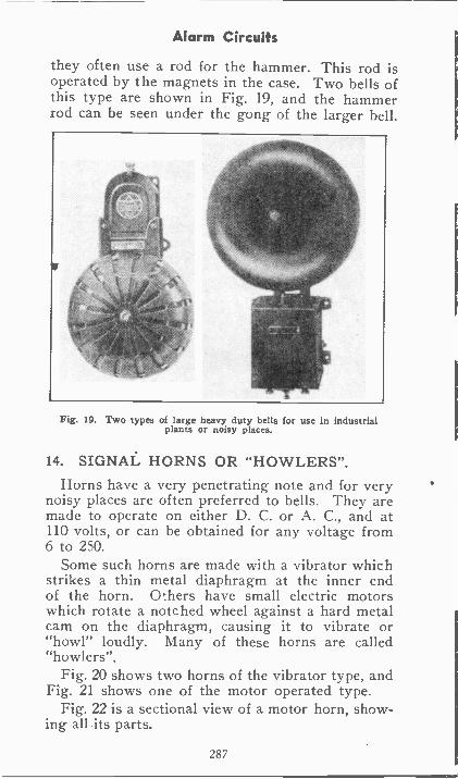
Alarm Circuits
they often use a rod for the hammer. This rod isoperated by the magnets in the case. Two bells ofthis type are shown in Fig. 19, and the hammerrod can be seen under the gong of the larger bell.
Fig. 19. Two types of large heavy duty bells for use in industrialplants or noisy places.
14. SIGNAL HORNS OR "HOWLERS".Horns have a very penetrating note and for very
noisy places are often preferred to bells. They aremade to operate on either D. C. or A. C., and at110 volts, or can be obtained for any voltage from6 to 250.
Some such horns are made with a vibrator whichstrikes a thin metal diaphragm at the inner endof the horn. Others have small electric motorswhich rotate a notched wheel against a hard metalcam on the diaphragm, causing it to vibrate or"howl" loudly. Many of these horns are called"howlers".
Fig. 20 shows two horns of the vibrator type, andFig. 21 shows one of the motor operated type.
Fig. 22 is a sectional view of a motor horn, show-ing all its parts.
287
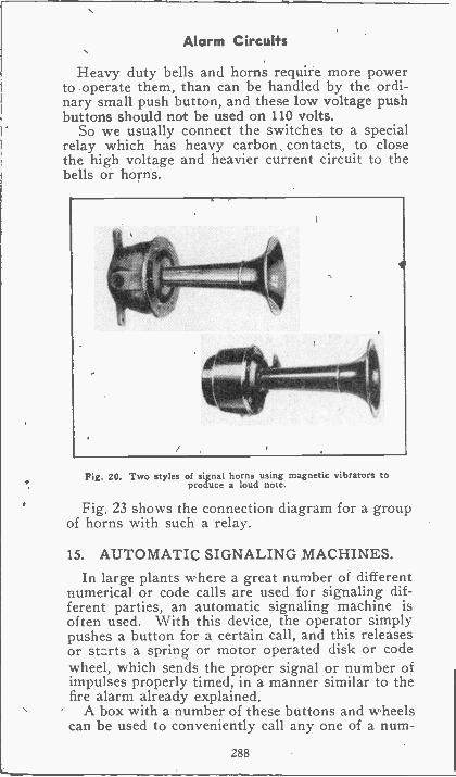
Alarm Circuits
Heavy duty bells and horns require more powerto operate them, than can be handled by the ordi-nary small push button, and these low voltage pushbuttons should not be used on 110 volts.
So we usually connect the switches to a specialrelay which has heavy carbon contacts, to closethe high voltage and heavier current circuit to thebells or horns.
Fig. 20. Two styles of signal horns using magnetic vibrators toproduce a loud note.
Fig. 23 shows the connection diagram for a groupof horns with such a relay.
15. AUTOMATIC SIGNALING MACHINES.In large plants where a great number of different
numerical or code calls are used for signaling dif-ferent parties, an automatic signaling machine isoften used. With this device, the operator simplypushes a button for a certain call, and this releasesor starts a spring or motor operated disk or codewheel, which sends the proper signal or number ofimpulses properly timed, in a manner similar to thefire alarm already explained.
A box with a number of these buttons and wheelscan be used to conveniently call any one of a num-
288
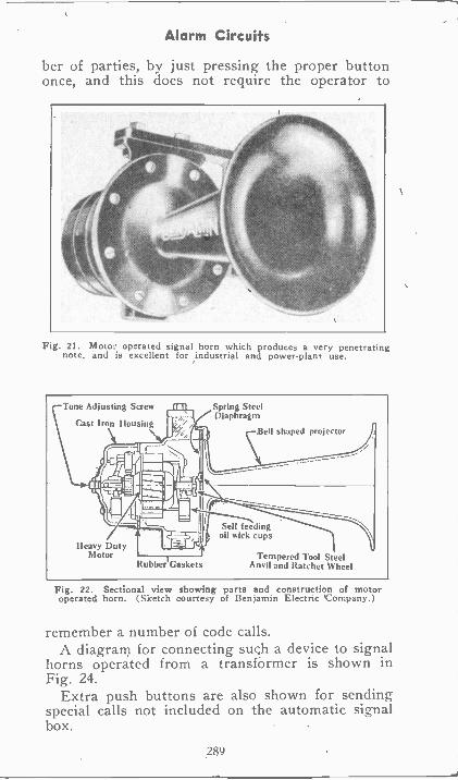
Alarm Circuits
ber of parties, by just pressing the proper buttononce, and this does not require the operator to
Fig. 21. Motor operated signal horn which produces a very penetratingnote, and is excellent for industrial and power -plant use.
Tone Adjusting Screw fl
Cast Iron Housing
1.1M
A
1
iIL
J11-671.11(Ming
Heavy DutyMotor
RublveriGaskets
Spring SteelDiaphragm
Bell shaped projector
Self feedingoil wick cups
Tempered Tool SteelAnvil and Ratchet Wheel
Fig. 22. Sectional view showing parts and construction of motoroperated horn. (Sketch courtesy of Benjamin Electric 'Company.)
remember a number of code calls.A diagram for connecting such a device to signal
horns operated from a transformer is shown inFig. 24.
Extra push buttons are also shown for sendingspecial calls not included on the automatic signalbox.
289
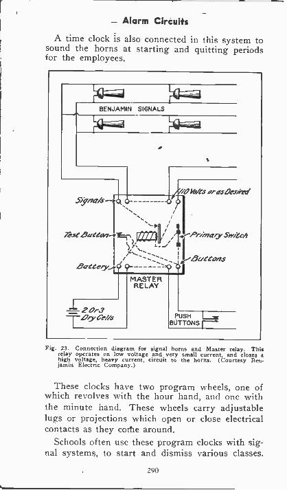
Alarm Circuits
A time clock is also connected in this system tosound the horns at starting and quitting periodsfor the employees.
Fig. 23. Connection diagram for signal horns and Master relay. Thisrelay operates on low voltage and very small current, and closes ahigh voltage, heavy current, circuit to the horns. (Courtesy Ben-jamin Electric Company.)
These clocks have two program wheels, one ofwhich revolves with the hour hand, and one withthe minute hand. These wheels carry adjustablelugs or projections which open or close electricalcontacts as they corhe around.
Schools often use these program clocks with sig-nal systems, to start and dismiss various classes.
290
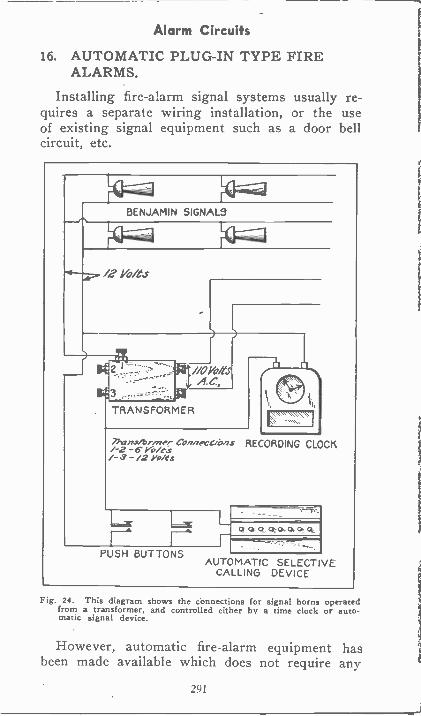
Alarm Circuits
16. AUTOMATIC PLUG-IN TYPE FIREALARMS.
Installing fire -alarm signal systems usually re-quires a separate wiring installation, or the useof existing signal equipment such as a door bellcircuit, etc.
BENJAMIN SIGNALS
/2 Wes
A.C.
TRANSFORMER
faN
1'1Tran4/brrner COlmeceins RECORDING CLOCK1-2 -6 Yo/ts/- -/2 Yo/es
LF-6 1n
PUSH BUTTONS
QQoaa..aCca
AUTOMATIC SELECTIVECALLING DEVICE
Fig. 24. This diagram shows the connections for signal horns operatedfrom a transformer, and controlled either by a time clock or auto-matic signal device.
However, automatic fire -alarm equipment hasbeen made available which does not require any
291
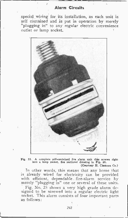
Alarm Circuits
special wiring for its installation, as each unit isself contained and is put in operation by merely"plugging in" to any regular electric convenienceoutlet or lamp socket.
Fig. 25. A complete self-contained fire alarm unit that screws rightinto a lamp socket. See sectional drawing in Fig. 26.
(Courtesy H. Chanson Co.)
In other words, this means that any home thatis already wired for electricity can be providedwith efficient, dependable fire -alarm service bymerely "plugging in" one or several of these units.
Fig. No. 25 shows a very high grade alarm de-signed to be screwed into a regular electric lightsocket. This alarm consists of four important partsas follows:
292
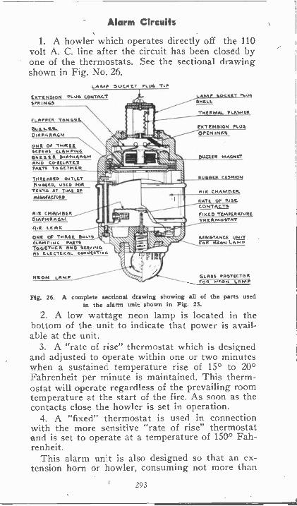
Alarm Circuits
1. A howler which operates directly off the 110volt A. C. line after the circuit has been closed byone of the thermostats. See the sectional drawingshown in Fig. No. 26.
LA MP DOCK ET ALLA, TIP
IR AT ENDH)FI PLUG CONTACTSFR INC,
11EW U.N.
D IAPHRAGM
%%%
ONE OF THARWIENS CLAMPING
IAA ND C/SRELATISPARTS To GEIPARR
THitFUNNED. LIMO FOR
TEsTs AT 11A1 OFmilliuFF CM*
AIR CHAMBERDIAPHRAGM
R LEAK
11t.i.. I:""M.N./Nam&I/ SIN;141..197._.
CLANS arsLTS 'iiii.' ig--1TOGETHER AND STATING , ,A.....1.1.- ...- ,AS IL Lt ("MEAL comileTNA -..;
LAFA SSHELL
PLC
THERM LASHIO'
EXTENSION PLUGOPENINGS
ESUZZER MAGNET
1111)511KR CUSHION
AIR CHANIOILR.
RAT! OF RISECONTACTS
I1(0 TRMPERATURETHERMOSTAT
RESISTANCE UNITFc/11.Amp
NEON LAMP GLASS PROTECTOR-----___ FOR FITON LAMP
S.L.%Mks
***
Mg. 26. A complete sectional drawing showing all of the parts usedin the alarm unit shown in Fig. 25.
2. A low wattage neon lamp is located in thebottom of the unit to indicate that power is avail-able at the unit.
3. A "rate of rise" thermostat which is designedand adjusted to operate within one or two minuteswhen a sustained temperature rise of 15° to 20°Fahrenheit per minute is maintained. This therm-ostat will operate regardless of the prevailing roomtemperature at the start of the fire. As soon as thecontacts close the howler is set in operation.
4. A "fixed" thermostat is used in connectionwith the more sensitive "rate of rise" thermostatand is set to operate at a temperature of 150° Fah-renheit.
This alarm unit is also designed so that an ex-tension horn or howler, consuming not more than
293
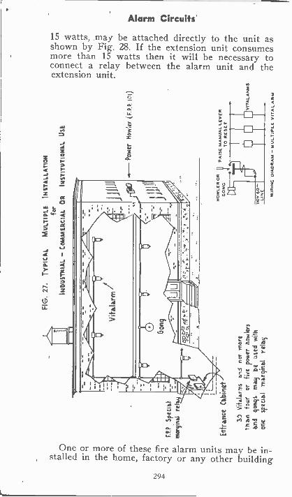
00
CD
P3In rp
,C)
0 ry
`-F
P.P
Spe
cial
0V
2-m
argi
nal r
elay
-tPI
0cn
Ent
ranc
e C
abin
et
C7"
-< ro
10 V
itwia
rms
and
no, m
are
Tha
n fo
uror
five
pow
er h
owle
rsan
d go
ngs
may
beus
ed w
ithon
esp
ecia
lm
argi
nal
rela
y
FIG
. 27.
TY
PIC
AL
MU
LTIP
LEIN
ST
ALL
AT
ION
for
IND
US
TR
IAL
- C
OIA
ME
RC
IAL
OR
INS
TIT
UT
ION
AL
USE
.-P
ower
how
ler
(F
. P. P
. IN
)
HO
WLE
R O
RG
ON
G
110V
60
-LI
NE
RA
ISE
MA
NU
AL
LEV
ER
TO
RE
SE
T
VIT
ALA
NP
AS
WIR
ING
DIA
GR
AM
- M
ULT
IPLE
VIT
AL
AR
M
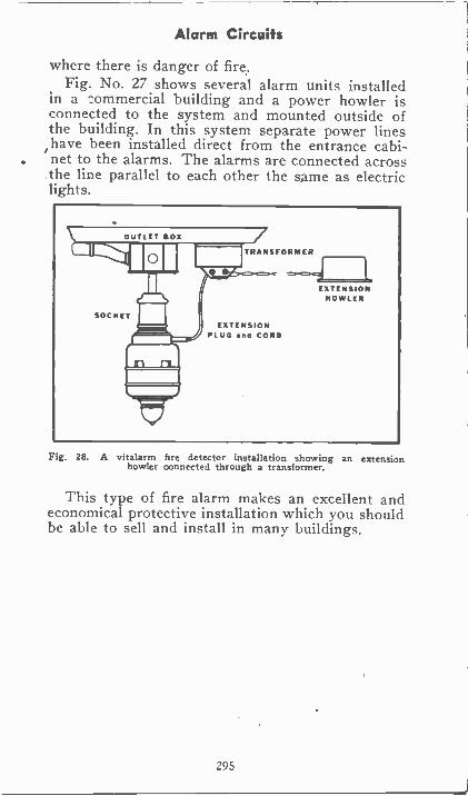
Alarm Circuits
where there is danger of fire.Fig. No. 27 shows several alarm units installed
in a :ommercial building and a power howler isconnected to the system and mounted outside ofthe building. In this system separate power lineshave been installed direct from the entrance cabi-net to the alarms. The alarms are connected acrossthe line parallel to each other the same as electriclights.
Fig. 28. A vitalarm fire detector installation showing an extensionhowler connected through a transformer.
This type of fire alarm makes an excellent andeconomical protective installation which you shouldbe able to sell and install in many buildings.
295
EXAMINATION QUESTIONS
1-(a) What is the advantage of using a holdingrelay in an alarm circuit? (h) What rule shouldbe followed in connecting up a holding relay?
2-(a) About what temperature is required tomelt the metal used in a fusable link? (b) Is themetal soft or hard?
3-What advantage is there in using a lockswitch in connection with a Burglar Alarm Circuit?
4-For what purpose is a glass used in a firealarm box?
5-Copy diagram No. 17 and trace the circuitthrough which current would flow when thermo-stat "D" is closed.
6-What kind of a signal device would you selectfor use in noisy places?
7-Is it advisable to use ordinary small pushbutton switches to control heavy duty bells andhorns? Why?
8-How is tinfoil used in connection with a Burg-lar Alarm system?
9-Why doesn't the relay coil in Fig. 7, attractthe armature, inasmuch as current is flowingthrough the coil?
10-Are the horns shown in Fig. 23, connectedin series or parallel with each other?
296
Signal System Installation
INSTALLATION
OF CALL AND SIGNAL SYSTEMS
Now that you have learned the operating prin-ciples of signal equipment and circuits, and knowhow to trace the diagrams and plans, you will wantto know more about how to install them.
In making any electrical installation, the firstthing should be the plan or layout, and circuitdiagram. So as soon as we have decided upon thetype of system desired and how it should operateto give best service, we should decide on the loca-tion of the various parts, and then lay out the cir-cuits accordingly.
Complete wiring diagrams are usually suppliedby the architects who draw up the plans for newbuildings. In the case of large power or industrialplants the plans are generally drawn up by theCompany Engineers. However, if such plans arenot furnished, you should at least make up a roughlayout before any work is started.
The plan can be drawn approximately to scale forthe various distances between devices, or length ofwire runs, and this will enable you to estimate andselect the required materials with best economy.
Then, by following a circuit diagram, many mis-takes and time losses can be avoided in making thefinal connections.
In drawing up plans, or in copying them fromother prints, it is usually much easier to sketch theparts and devices on the paper first, in about thesame location and proportional spacing as in theoriginal plan, or as they are to be installed in thebuilding. Then draw in the wires and circuits oneat a time, keeping them as straight and simple aspossible. Lay out the wires and connections first toget the desired operation and results. Then go overthe plan again, and possibly redraw it to simplifyit and shorten wires, making use of "commonwires" eliminating unnecessary crossed wires, etc.
297
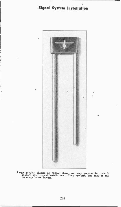
Signal System Installation
0
Large tubular chimes as shown above are very popular for use inmodern door signal installations. They are new and easy to sellto many home owners.
298
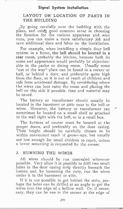
Signal System Installation
LAYOUT OR LOCATION OF PARTS INTHE BUILDING
_By going carefully over the building with theplans, and usirfg good common sense in choosingthe location for the various apparatus and wireruns, you can make a more satisfactory job andsave additional time and labor on the installation.
For example, when installing a simple door bellsystem in a home, the bell should be located in arear room, probably the kitchen, because both itsnoise and appearance would probably be objection-able in the parlor or dining room. Usually some"out of the way" place can be found in a corner orhall, or behind a door, and preferably quite highfrom the floor, so it is out of reach of children andsafe from accidental damage. By considering wherethe wires can best enter the room and placing thebell on this side if possible. time and material maybe saved.
The battery or transformer should usually belocated in the basement or attic near to the bell orwires. However, the battery or transformer cansometimes be located on a small shelf or attachedto the wall right with the bell, or in a small box.
The buttons of course must be located at theproper doors, and preferably on the door casing.Their height should be carefully chosen to bewithin convenient reach of grown-ups, but usuallynot low enough for small children to reach, unlessa lower mounting is requested by the owner.
2. RUNNING THE WIRESAll wires should be run concealed whenever
possible. Very often it is possible to drill two smallholes in the door casing strip directly beneath thebutton and, by loosening the strip, run the wiresunder it to the basement or attic.
If it is not possible to get behind the strip, per-haps the holes can be drilled at an angle to get thewires into the edge of a hollow wall. Or, if neces-sary, they can be run in the corner at the edge of
299
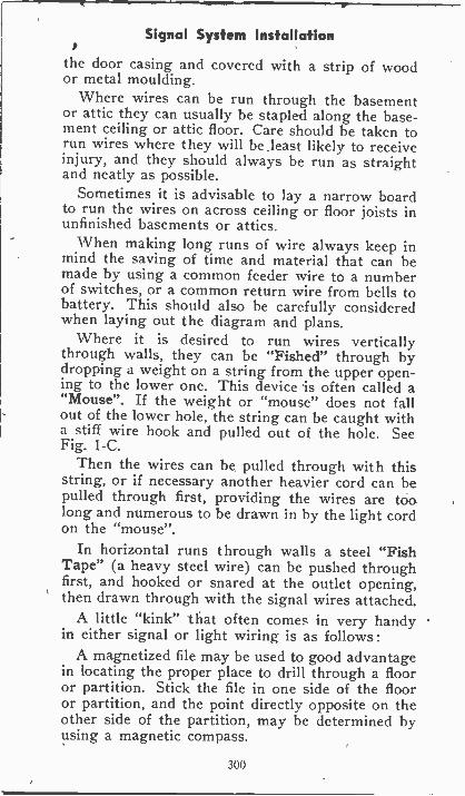
Signal System Installation
the door casing and covered with a strip of woodor metal moulding.
Where wires can be run through the basementor attic they can usually be stapled along the base-ment ceiling or attic floor. Care should be taken torun wires where they will be least likely to receiveinjury, and they should always be run as straightand neatly as possible.
Sometimes it is advisable to lay a narrow boardto run the wires on across ceiling or floor joists inunfinished basements or attics.
When making long runs of wire always keep inmind the saving of time and material that can bemade by using a common feeder wire to a numberof switches, or a common return wire from bells tobattery. This should also be carefully consideredwhen laying out the diagram and plans.
Where it is desired to run wires verticallythrough walls, they can be "Fished" through bydropping a weight on a string from the upper open-ing to the lower one. This device is often called a"Mouse". If the weight or "mouse" does not fallout of the lower hole, the string can be caught witha stiff wire hook and pulled out of the hole. SeeFig. 1-C.
Then the wires can be pulled through with thisstring, or if necessary another heavier cord can bepulled through first, providing the wires are toolong and numerous to be drawn in by the light cordon the "mouse".
In horizontal runs through walls a steel "FishTape" (a heavy steel wire) can be pushed throughfirst, and hooked or snared at the outlet opening,then drawn through with the signal wires attached.
A little "kink" that often comes in very handyin either signal or light wiring is as follows :
A magnetized file may be used to good advantagein locating the proper place to drill through a flooror partition. Stick the file in one side of the flooror partition, and the point directly opposite on theother side of the partition, may be determined byusing a magnetic compass.
300
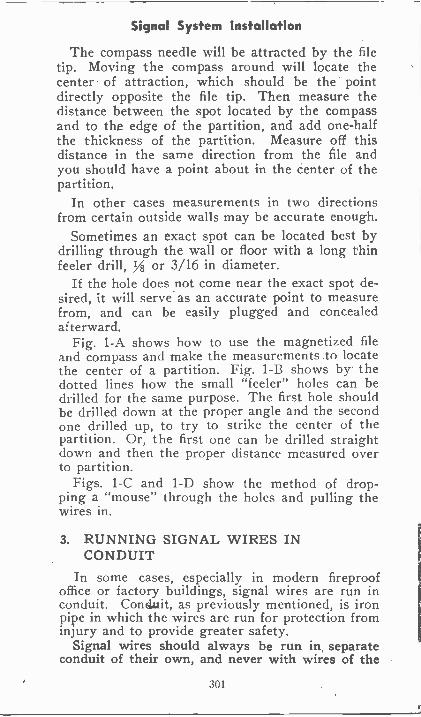
Signal System Installation
The compass needle will be attracted by the filetip. Moving the compass around will locate thecenter of attraction, which should be the pointdirectly opposite the file tip. Then measure thedistance between the spot located by the compassand to the edge of the partition, and add one-halfthe thickness of the partition. Measure off thisdistance in the same direction from the file andyou should have a point about in the center of thepartition.
In other cases measurements in two directionsfrom certain outside walls may be accurate enough.
Sometimes an exact spot can be located best bydrilling through the wall or floor with a long thinfeeler drill, 1/8 or 3/16 in diameter.
If the hole does not come near the exact spot de-sired, it will serve as an accurate point to measurefrom, and can be easily plugged and concealedafterward.
Fig. 1-A shows how to use the magnetized fileand compass and make the measurements to locatethe center of a partition. Fig. 1-B shows by thedotted lines how the small "feeler" holes can bedrilled for the same purpose. The first hole shouldbe drilled clown at the proper angle and the secondone drilled up, to try to strike the center of thepartition. Or, the first one can he drilled straightdown and then the proper distance measured overto partition.
Figs. 1-C and 1-D show the method of drop-ping a "mouse" through the holes and pulling thewires in.
3. RUNNING SIGNAL WIRES INCONDUIT
In some cases, especially in modern fireproofoffice or factory buildings, signal wires are run inconduit. Conduit, as previously mentioned, is ironpipe in which the wires are run for protection frominjury and to provide greater safety.
Signal wires should always be run in separateconduit of their own, and never with wires of the
301
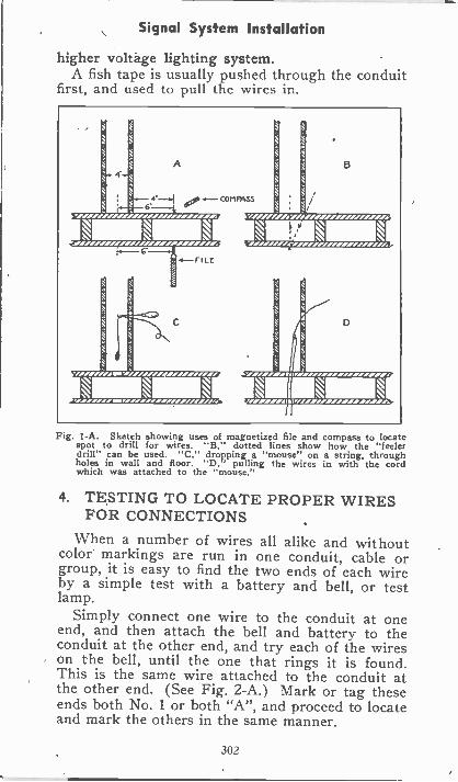
Signal System Installation
higher voltage lighting system.A fish tape is usually pushed through the conduit
first, and used to pull the wires in.
Fig. 1-A. Sketch showing uses of magnetized file and compass to loca espot to drill for wires. "B," dotted lines show how the "feelerdrill" can be used. "C," dropping a "mouse" on a string, throughholes in wall and floor. "D, pulling the wires in with the cordwhich was attached to the "mouse."
4. TESTING TO LOCATE PROPER WIRESFOR CONNECTIONS
When a number of wires all alike and withoutcolor markings are run in one conduit, cable orgroup, it is easy to find the two ends of each wireby a simple test with a battery and bell, or testlamp.
Simply connect one wire to the conduit at oneend, and then attach the bell and battery to theconduit at the other end, and try each of the wireson the bell, until the one that rings it is found.This is the same wire attached to the conduit atthe other end. (See Fig. 2-A.) Mark or tag theseends both No. 1 or both "A", and proceed to locateand mark the others in the same manner.
302
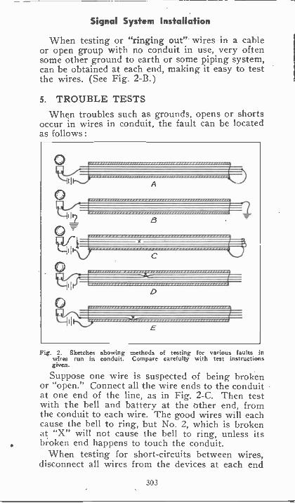
Signal System Installation
When testing or "ringing out" wires in a cableor open group with no conduit in use, very oftensome other ground to earth or some piping system,can be obtained at each end, making it easy to testthe wires. (See Fig. 2-B.)
5. TROUBLE TESTSWhen troubles such as grounds. opens or shorts
occur in wires in conduit, the fault can be locatedas follows :
O
0
o
O
11 4
82
D
Fig. 2. Sketches showing methods of testing for various faults inwires run in conduit. Compare carefully with test instructionsgiven.
Suppose one wire is suspected of being brokenor "open." Connect all the wire ends to the conduitat one end of the line, as in Fig. 2-C. Then testwith the bell and battery at the other end, fromthe conduit to each wire. The good wires will eachcause the bell to ring, but No. 2, which is brokenat "X" will not cause the bell to ring, unless itsbr.oken end happens to touch the conduit.
When testing for short-circuits between wires,disconnect all wires from the devices at each end
303
Signal System Installation
of the line and test as in Fig. 2-D.When the bell is connected to wires Nos. 1 and 2
it will ring, as they are shorted or touching eachother at "X", through damaged insulation. Con-necting the bell to any other pair will not causeit to ring.
Sometimes one wire becomes grounded to theconduit because of defective insulation as in Fig.2-E.
For this test we again disconnect the devicesfrom the wires, and connect the test bell and bat-tery as shown.
With one test lead on the conduit, try the otherlead on each wire. It will not ring on Nos. 1, 2, or3, but will ring on No. 4 which is touching the pipeat "X", thus making a closed circuit for the testbell.
6. EMERGENCY WIRES, AND PULLINGIN REPLACEMENTS
Where long runs of wires are installed in conduitor signal cables, it is common practice to includeone or more extra wires tor use in case any of theothers become damaged.
. This is especially good practice with cables, be-cause it is difficult to remove or repair the brokenwire. In a conduit system, where no extra wiresare provided and a new wire must be run in toreplace a broken or grounded one, it is sometimeseasier to pull out all wires, and pull a new one backin with them.
W here this is not practical or possible, it some-times saves time and money to pull out the brokenor bad wire, and then attach two good wires to theend of one of the remaining wires, and pull it out,pulling in the two good ones with it. This replacesboth the bad wire and the one good wire pulled out.
If the bad wire was not broken but only grounded,it can be used to pull in the new wire ; but, ofcourse, a broken wire cannot be used for this pur-pose. Therefore, it is often advisable to sacrificeone good wire, to pull in two new ones.
304
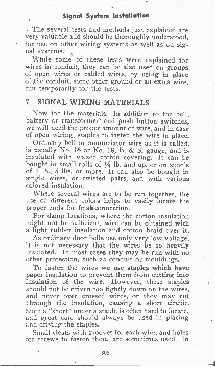
Signal System Installation
The several tests and methods just explained arevery valuable and should be thoroughly understood,for use on other wiring systems as well as on sig-nal systems.
While some of these tests were explained forwires in conduit, they can be also used on groupsof open wires or cabled wires, by using in placeof the conduit, some other ground or an extra wire,run temporarily for the tests.
7. SIGNAL WIRING MATERIALS
Now for the materials. In addition to the bell,battery or transformer; and push button switches,we will need the proper amount of wire, and in caseof open wiring, staples to fasten the wire in place.
Ordinary bell or annunciator wire as it is called,is usually No. 16 or No. 18, B. & S. gauge, and isinsulated with waxed cotton covering. It can bebought in small rolls of IA lb. and up, or on spoolsof 1 lb., 5 lbs. or more. It can also be bought insingle wires, or twisted pairs, and with variouscolored insulation.
Where several wires are to be run together, theuse of different colors helps to easily locate theproper ends for final, connection.
For damp locations, where the cotton insulationmight not be sufficient, wire can be obtained witha light rubber insulation and cotton braid over it.
As ordinary door bells use only very low voltage,it is not necessary that the wires be so heavilyinsulated. In most cases they may be run with noother protection, such as conduit or mouldings.
To fasten the wires we use staples which havepaper insulation to prevent them from cutting intoinsulation of the wire. However, these staplesshould not be driven too tightly down on the wires,and never over crossed wires, or they may cutthrough the insulation, causing a short circuit.Such a "short" under a staple is often hard to locate,and great care should always be used in placingand driving the staples.
Small cleats with grooves for each wire, and holesfor screws to fasten them, are sometimes used. In
305
Signal System Installation
other cases where twisted pairs of wires are run,a small nail with a broad insulating head is drivenbetween the two wires, so the head holds them inplace. Fig. 3 shows several sizes of insulatedstaples, and Fig: 4 shows the nail and cleats men-tioned above.
Fig. 3. Several different sizes and styles of insulated staples usedin bell wiring.
On installations where a large number of wiresare to be run in a group, cables with the desirednumber of wires can be obtained. These wires areusually marked by different colored insulation, sothat the ends of any certain wire can be quicklyand easily located at each end of the cable. Suchcables simplify the running of the wires, save spaceand time, and make a much neater job in officesand places where numerous separate wires wouldbe undesirable.
In large signal installations terminal blocks areused on some of the equipment, and all wires arebrought to numbered terminals on these blocks.Then with the plans, on which the wires can alsobe numbered, it is very simple to make proper con-nections of cables with dozens or even hundreds ofwires.
This is common practice with telephone installa-tions and elevator signals, and also on modernradio sets, as well as for office and industrial callsystems.
8. CAUTION NECESSARY FOR SAFE ANDRELIABLE WIRING
Considerable care should be used when drawingbell wires through holes and openings, or the insu-
306
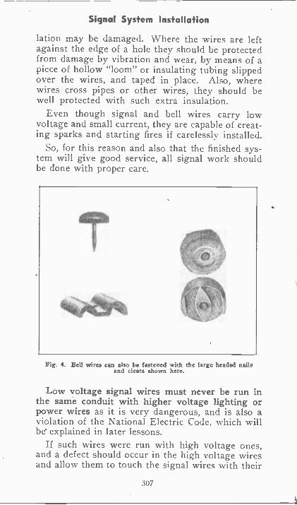
Signal System Installation
lation may be damaged. Where the wires are leftagainst the edge of a hole they should be protectedfrom damage by vibration and wear, by means of apiece of hollow "loom" or insulating tubing slippedover the wires, and taped in place. Also, wherewires cross pipes or other wires, they should bewell protected with such extra insulation.
Even though signal and bell wires carry lowvoltage and small current, they are capable of creat-ing sparks and starting fires if carelessly installed.
So, for this reason and also that the finished sys-tem will give good service, all signal work shouldbe done with proper care.
Fig. 4. Bell wires can also be fastened with the large headed nailsand cleats shown here.
Low voltage signal wires must never be run inthe same conduit with higher voltage lighting orpower wires as it is very dangerous, and is also aviolation of the National Electric Code, which willbe explained in later lessons.
If such wires were run with high voltage ones,and a defect should occur in the high voltage wiresand allow them to touch the signal wires with their
307
Signal System Installation
thinner insulation, it would create a serious fire andshock ;hazard.
When installing bell transformers, the wires fromthe lighting circuit to the transformer primary mustbe regular No. 14 rubber covered lighting wire, andmust run in conduit, armored cable, or approvedfashion for 110 volt wiring, according to the code ofthat particular town or territory.
When making splices or connections to devicesall wires should be well cleaned of insulation andall connections carefully made and well tightened.Splices in wires should be carefully soldered andwell taped, to make secure and well insulated joints.
Any bell or signal system should be thoroughlytested before leaving it as a finished job. Pride inyour work and neatness and thoroughness in everyjob should be your rule in all electrical iwork. Thatwill be the surest way to make satisfied customersand success, in your job or business.
9. TROUBLE SHOOTINGIn each section of this work on signal devices
and circuits, common troubles and methods of lo-cating them have been covered. In order to applyyour knowledge of these things to solve anytroubles in signal systems, your first step should beto get a good mental picture of the system, eitherfrom the plan or by looking over the system andmaking a rough sketch of the devices and connec-tions.
Then go over it one part at a time Coolly andCarefully, and try to determine from the faulty ac-tion or symptoms of the system where the troublemay be.
10. KEEP COOL AND USE A PLAN AND ASYSTEM
A great mistake made by many untrained menin trouble shooting, is that they get rattled andworried as soon as they encounter a difficult prob-lem of this nature. They forget that a plan or rough
308
Signal System Installation
sketch of the wiring will usually be of the greatesthelp, and they make a few wild guesses as to whatthe trouble is. If these don't .hit it, they often getstill more rattled and indefinite in their efforts, andas a result sometimes mess up the system makingit worse instead of improving it.
Remember that Every Trouble Can Be Found,and Someone Is Going to Find It. If you can do it,it will be to your credit and often put money inyour pocket, or get you a promotion.
You can find any fault, by thoughtful systematictesting. of each circuit and device and applying theknowledge you have of this work.
In general, a good rule to follow is to first testthe source of current supply. See that it is alive andat proper voltage. A test lamp or voltmeter willdo this nicely.
Then test the devices that fail to operate, usinga portable battery and test wires to make sure thedevice itself is not at fault, or has no looseterminals.
If the power supply and all bells, relays, andswitches are tested and 0. K., then start testingthe main wires and circuits with the proper switchesclosed to energize them. Use a test lamp of theproper voltage, or a voltmeter, to make sure thecurrent can get through the lines.
No one can remember all these things perfectlythe first time, but referring back to them and tryingthem out on the job at every opportunity is thequickest and surest way to fix them in your mind.
Never be ashamed to refer to a plan or noteswhen you have a problem of connection or othertrouble. The most successful electricians and engi-neers always follow plans.
When a system has several separate circuits,test them one at a time and mark them off on theplan or sketch as each is proven 0. K. In this man-ner you know at all times how far you have gone,
309
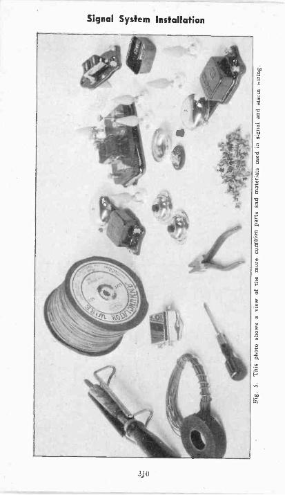
Fig.
5.T
his
phot
o sh
ows
a vi
ew o
f th
e m
ore
cuM
Mon
par
ts a
nd m
ater
ials
use
d in
sig
nal a
ndai
a,in
wir
ing.
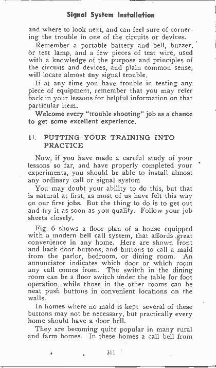
Signal System Installation
and where to look next, and can feel sure of corner-ing the trouble in one of the circuits or devices.
Remember a portable battery and bell, buzzer,or test lamp, and a few pieces of test wire, usedwith a knowledge of the purpose and principles ofthe circuits and devices, and plain common sense,will locate almost any signal trouble.
If at any time you have trouble in testing anypiece of equipment, remember that you may referback in your lessons for helpful information on thatparticular item.
Welcome every "trouble shooting" job as a chanceto get some excellent experience.
11. PUTTING YOUR TRAINING INTOPRACTICE
Now, if you have made a careful study of yourlessons so far, and have properly completed yourexperiments, you should be able to install almostany ordinary call or signal system
You may doubt your ability to do this, but thatis natural at first, as most of us have felt this wayon our first jobs. But the thing to do is to get outand try it as soon as you qualify. Follow your jobsheets closely.
Fig. 6 shows a floor plan of a house equippedwith a modern bell call system, that affords greatconvenience in any home. Here are shown frontand back door buttons, and buttons to call a maidfrom the parlor, bedroom, or dining room. Anannunciator indicates which door or which roomany call comes from. The switch in the diningroom can be a floor switch under the table for footoperation, while those in the other rooms can beneat push buttons in convenient locations on thewalls.
In homes where no maid is kept several of thesebuttons may not be necessary, but practically everyhome should have a door bell.
They are becoming quite popular in many ruraland farm homes. In these homes a call bell from
311
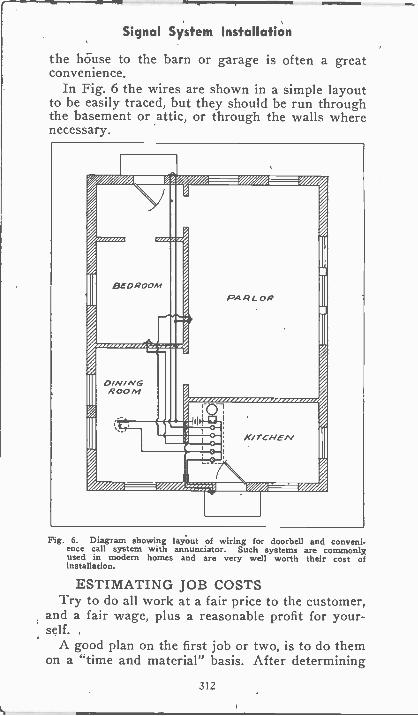
Signal System Installation
the house to the barn or garage is often a greatconvenience.
In Fig. 6 the wires are shown in a simple layoutto be easily traced, but they should be run throughthe basement or attic, or through the walls wherenecessary.
Fig. 6. Diagram showing layout of wiring for doorbell and conveni-ence call system with annunciator. Such systems are commonlyused in modern homes and are very well worth their cost ofinstallation.
ESTIMATING JOB COSTSTry to do all work at a fair price to the customer,
and a fair wage, plus a reasonable profit for your-self.
A good plan on the first job or two, is to do themon a "time and material" basis. After determining
312
Signal System Installation
the type of system desired and parts and materialsneeded, let the customer buy them, and then chargefor your time on installing them by the hour.
Keep a record of your time, wages, materials,and costs, and these will help you estimate futurejobs quite accurately. Then you can buy your ownmaterials, and charge 25 per cent or more for hand-ling them and for overhead or miscellaneous ex-pense ; in addition to a good wage for your time,all in the estimate figure.
In many cases, time and money can be saved onalarm installations by arranging the relays, bells,batteries, and reset switch all on one panel or shelfboard, in advance at your home or shop. Thenwhen you go to the job, it is only necessary tomount this assembled unit and install the wires andproper switches.
And again let us emphasize the value of doingall work neatly and with good workmanship, bothfor the appearance of the job, and for its quality
A customer is usually better satisfied in the end,to have a first class .job done at a fair price, thanto have a poor job' at a cheap price.
12. GOOD WORKMANSHIP IMPORTANTIn every job you do, from the smallest door bell
system to the most elaborate burglar or fire alarmsystem, make a practice of doing nothing but firstclass work-work that will be a credit to your pro-fession, your school, and yourself.
Whether working for a customer or an employer,start building your reputation with your first job,and keep this thought in mind on all jobs.13. VALUE OF ADVERTISING
Don't hesitate to let the people in your neighbor-hood know of your training and ability. With justa little confidence and real ambition you can domany profitable jobs. Prove it to them and toyourself, and be proud of your training, and everyjob well done.
313
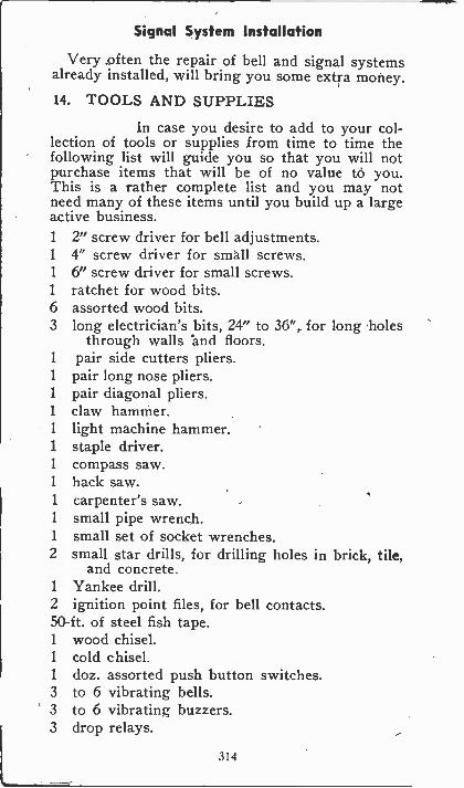
Signal System Installation
Very .often the repair of bell and signal systemsalready installed, will bring you some extra money.
14. TOOLS AND SUPPLIES
In case you desire to add to your col-lection of tools or supplies from time to time thefollowing list will guide you so that you will notpurchase items that will be of no value t6 you.This is a rather complete list and you may notneed many of these items until you build up a largeactive business.1 2" screw driver for bell adjustments.1 4" screw driver for small screws.1 6" screw driver for small screws.1 ratchet for wood bits.6 assorted wood bits.3 long electrician's bits, 24" to 36", for long holes
through walls and floors.1 pair side cutters pliers.1 pair long nose pliers.1 pair diagonal pliers.1 claw hammer.1 light machine hammer.1 staple driver.1 compass saw.1 hack saw.1 carpenter's saw.1 small pipe wrench.1 small set of socket wrenches.2 small star drills, for drilling holes in brick, tile,
and concrete.1 Yankee drill.2 ignition point files, for bell contacts.50 -ft. of steel fish tape.1 wood chisel.1 cold chisel.1 doz. assorted push button switches.3 to 6 vibrating bells.3 to 6 vibrating buzzers.3 drop relays.
314
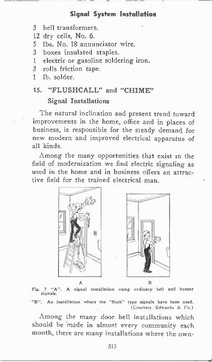
Signal System Installation
3 bell transformers.12 dry cells, No. 6.5 lbs. No. 18 annunciator wire.3 boxes insulated staples.1 electric or gasoline soldering iron.3 rolls friction tape.1 lb. solder.
15. "FLUSHCALL" and "CHIME"Signal Installations
The natural inclination and present trend towardimprovements in the home, office and in places ofbusiness, is responsible for the steady demand fornew modern and improved electrical apparatus ofall kinds.
Among the many opportunities that exist in thefield of modernization we find electric signaling asused in the home and in business offers an attrac-tive field for the trained electrical man.
A
Fig. 7 "A". A signal installation using ordinary bell and buzzersignals.
"B". An installation where the "flush" type signals have been used.(Courtesy Edwards & Co.)
Among the many door bell installations whichshould be made in almost every community eachmonth, there are many installations where the own -
315
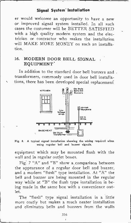
Signal System Installation
er would welcome an opportunity to have a newor improved signal system installed. In all suchcases the customer will be BETTER SATISFIEDwith a high quality modern system and the elec-trician or contractor who makes the installationwill MAKE MORE MONEY on such an installa-tion.
16. MODERN DOOR BELL SIGNALEQUIPMENT
In addition to the standard door bell buzzers andtransformers, commonly used in door bell installa-tions, there has been developed special replacement
KITCHEN
BASEMENT
C4roZigifreN.
LowVoltage
Wires
Old StyleBells andBuzzers
110-VoltRec.Fcie
Wires
Fig. 8. A typical signal installation showing the wiring required whenusing regular bell and buzzer signals.
equipment which may be mounted flush with thewall and in regular outlet boxes.
Fig. 7 "A" and "B" show a comparison betweenthe appearance of a regular door bell and buzzer,and a modern "flush" type installation. At "A" thebell and buzzer are being mounted in the regularway while at "B" the flush type installation is be-ing made in the same box with a convenience out-let.
The "flush" type signal installation is a littlemore costly but makes a much neater installationand eliminates bells and buzzers from the walls
316
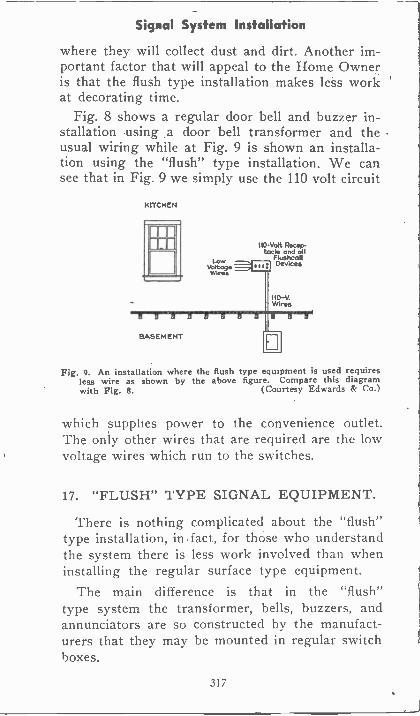
Signal System Installation
where they will collect dust and dirt. Another im-portant factor that will appeal to the Home Owneris that the flush type installation makes less workat decorating time.
Fig. 8 shows a regular door bell and buzzer in-stallation using .a door bell transformer and theusual wiring while at Fig. 9 is shown an installa-tion using the "flush" type installation. We cansee that in Fig. 9 we simply use the 110 volt circuit
KITCHEN
MDEW
BASEMENT
Lowvoltogewires
tiONOtt Recap -tad , and all
flushcallDevices
110-v.Wires
Fig. 9. An installation where the flush type equipment is used requiresless wire as shown by the above figure. Compare this diagramwith Fig. 8. (Courtesy Edwards & Co.)
which supplies power to the convenience outlet.The only other wires that are required are the lowvoltage wires which run to the switches.
17. "FLUSH" TYPE SIGNAL EQUIPMENT.
There is nothing complicated about the "flush"type installation, in fact, for those who understandthe system there is less work involved than wheninstalling the regular surface type equipment.
The main difference is that in the "flush"type system the transformer, bells, buzzers, andannunciators are so constructed by the manufact-urers that they may be mounted in regular switchboxes.
317
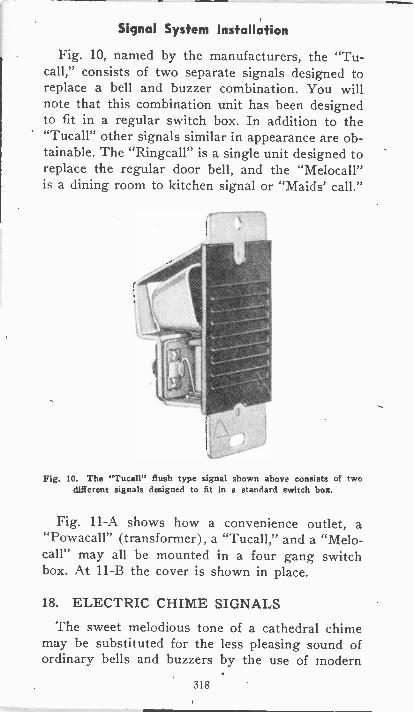
Signal System Installation
Fig. 10, named by the manufacturers, the "Tu-call," consists of two separate signals designed toreplace a bell and buzzer combination. You willnote that this combination unit has been designedto fit in a regular switch box. In addition to the"Tucall" other signals similar in appearance are ob-tainable. The "Ringcall" is a single unit designed toreplace the regular door bell, and the "Melocall"is a dining room to kitchen signal or "Maids' call."
Fig. 10. The "Tucall" flush type signal shown above consists of twodifferent signals designed to fit in a standard switch box.
Fig. 11-A shows how a convenience outlet, a"Powacall" (transformer), a "Tucall," and a "Melo-call" may all be mounted in a four gang switchbox. At 11-B the cover is shown in place.
18. ELECTRIC CHIME SIGNALS
The sweet melodious tone of a cathedral chimemay be substituted for the less pleasing sound ofordinary bells and buzzers by the use of modern
318
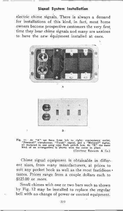
Signal System Installation
electric chime signals. There is always a demandfor installations of this kind, in fact, most homeowners become prospective customers the very firsttime they hear chime signals and many are anxiousto have the new equipment installed at once.
A
B
Fig. II. At "A" we have from left to right: convenience outlet,"Powacall" transformer, "Tucall" signal, and a "Melocall" signal,all mounted in one gang type flush switch box. At "B" the samekind of an arrangement is shown with the cover in place.
(Courtesy Edwards & Co.)
Chime signal equipment is obtainable in differ-ent sizes, from many manufacturers, at prices tosuit any pocket book as well as the most fastidioustastes. Prices range from a couple dollars each to$125.00 or more.
Small chimes with one or two bars such as shownby Fig. 12 may be installed to replace the regularbell with no change of power or control equipment.
319
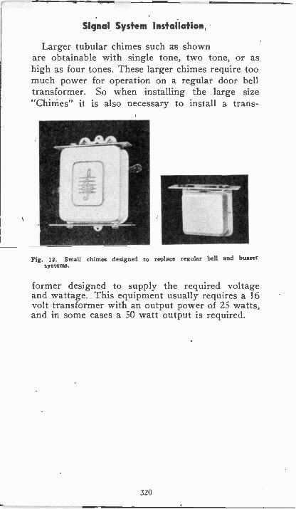
Signal System Installation
Larger tubular chimes such as shownare obtainable with single tone, two tone, or ashigh as four tones. These larger chimes require toomuch power for operation on a regular door belltransformer. So when installing the large size"Chimes" it is also necessary to install a trans -
Fig. 12. Small chimes designed to replace regular bell and buzzersystems.
former designed to supply the required voltageand wattage. This equipment usually requires a 16volt transformer with an output power of 25 watts,and in some cases a 50 watt output is required.
320
Signal System Installation
EXAMINATION QUESTIONS
1. In which part of the house is a door bell gen-erally located?
2. Should signal wires be run in conduit withthe power Or light wires?
' 3. Is it generally necessary to run low voltagebell wires in conduit?
4. What kind of wire should be used for the 110volt primary circuit leading to the bell trans-formers?
5. How are low voltage signal wires held inplace when run without conduit?
6. Why is insulation_used on bell wiring Staples?
7. In what part of the building should a belltransformer be located.
8. What two simple methods can be used to lo-cate the proper spot to cut or drill into a floor orpartition?
9. What is meant by a "mouse" as used in signalwiring? What is a "fish tape" used for?
10. What equipment would you use to test sig-nal wires for grounds, opens or shorts?
321
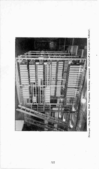
Str
owge
r (S
tep
-By
-Ste
p) D
ial T
elep
hone
Sw
itchi
ng e
quip
men
t (In
stal
lerP
at L
ogan
spor
t, In
dian
a).
TELEPHONY
Telephony is one of the most fascinating branchesof Electricity which we now find such an importantpart of our every day life that we accept it as amatter of course, and seldom give much attentionto the development which brought this interestingand valuable equipment to us.
During the year 1876, Alexander Graham Belltook out the first patent on the telephone. Thedefinition given by him in obtaining his patent wasas follows : An instrument for the transmission ofarticulate speech by electric current.
Although the telephone of today is completelyelectrically operated, the same fundamental operat-ing principle was involved in the operation of theold "Lovers Telephone" which has been a source ofamusement for many years. Thousands of youngfolks have enjoyed talking into an ordinary tin canand having their voice reproduced in another cansome distance away by means of a tightly drawnstring or wire attached between the two cans.This equipment although very crude was a steppingstone to the wonderful world wide system of today.
The writer can recall when telephones were firstbeing introduced for general use. In those days wethought it quite an accomplishment to telephoneover a distance of 50 miles. In fact, at that timeone would have more difficulty in talking over a dis-tance of 50 miles than we have today in carrying ona conversation with a person in almost any part ofthe world.
International Telephone Service is now availableto most points in Europe, Asia, Africa, Australia,Central America. Alsp to the Bermudas, Hawaiianand other Islands.
One may also step to the telephone and carry ona conversation with a party traveling on either ofseveral great litiers on the Atlantic Ocean.
323
Telephony
1. GREAT FIELD FOR SPECIALISTS WITHELECTRICAL TRAINING
To keep all this vast and marvelous system oftelephones functioning perfectly requires thousandsof well trained electrical men who ate specialistsin circuit tracing, trouble shooting, and care andadjustment of the relays, bells, coils, etc. Manymore men are required to install the thousands ofnew telephones constantly being added to this vastsystem.
2. TELEPHONE KNOWLEDGE VALUABLEIN ANY LINE OF ELECTRICAL WORK
The telephone field is one in which you can usemany of the principles that have been covered inthe preceding elementary and signal lessons. Andeven though you may not desire to specialize in orfollow telephone work, you should at least have anunderstanding of the fundamental principles of tele-phone equipment. Many power plants, factories,shops and offices have their own private telephonesystems, and in any line of electrical maintenancework you are likely to find good use for thisknowledge.
3. PRINCIPLES OF OPERATIONThe telephone is an instrument for transmitting
sounds and voice from one point to another. Tele-phones do not actually carry the sound itself, butinstead reproduce it by means of electric currentimpulses.
In order to understand how this is done, weshould first know something of the nature ofsound. Most everyone knows that any. sound istransmitted by means of waves in the air. Theseair waves may be set up by one's voice, clappingof hands, firing a gun, or anything that causes adisturbance of the air.
Different sounds have waves of different volumeand frequency. A loud sound has waves of greatervolume or energy, and a low or feeble sound haswaves of less volume or energy. A high pitched
324
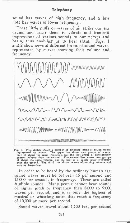
Telephony
sound has waves of high frequency, and a lownote has waves of lower frequency .
These little puffs or waves of air strike our eardrums and cause them to vibrate and transmitimpressions of various sounds to our nerves andbrain, thus enabling us to hear them. Figs. 1
and 2 show several different forms of sound waves,represented by curves showing their volume and.frequency.
Fig. 1. This sketch shows a number of different forms of sound wavesrepresented by curves. The upper line shows two groups of waves,both of about the same frequency, but the first group of considerablygreater volume than the second. The second line shows two groupsof about the same volume, but the first is of much lower frequencythan the second. The third line shows waves of varying volume andvarying frequency.
In order to be heard by the ordinary human ear,sound waves must be between 16 per second and15,000 per second, in frequency. These are calledAudible sounds. Many people cannot hear soundsof higher pitch or frequency than 8,000 to 9,000waves per second, and it is only the highest ofmusical or whistling notes that reach a frequencyof 10,000 or more per second.
Sound waves travel about 1,100 feet per second
325
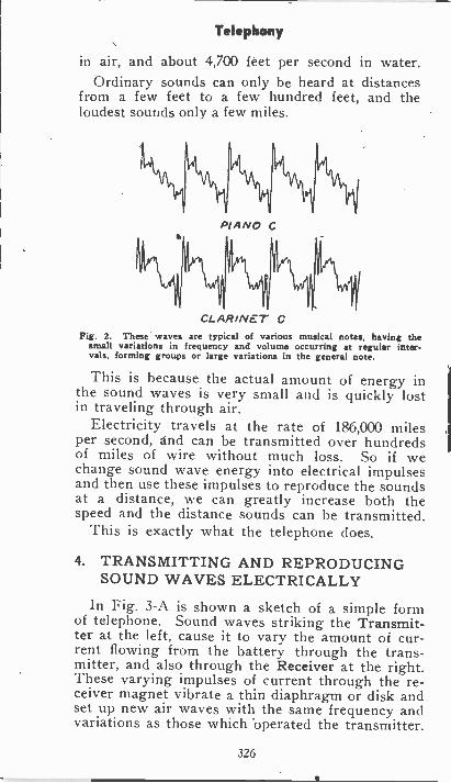
Telephony
in air, and about 4,700 feet per second in water.Ordinary sounds can only be heard at distances
from a few feet to a few hundred feet, and theloudest sounds only a few miles.
PJANO C
%11CLARINET C
Fig. 2. These waves are typical of various musical notes, having thesmall variations in frequency and volume occurring at regular inter-vals, forming groups or large variations in the general note.
This is because the actual amount of energy inthe sound waves is very small and is quickly lostin traveling through air.
Electricity travels at the rate of 186,000 milesper second, and can be transmitted over hundredsof miles of wire without much loss. So if wechange sound wave energy into electrical impulsesand then use these impulses to reproduce the soundsat a distance, we can greatly increase both thespeed and the distance sounds can be transmitted.
This is exactly what the telephone does.
4. TRANSMITTING AND REPRODUCINGSOUND WAVES ELECTRICALLY
In Fig. 3-A is shown a sketch of a simple formof telephone. Sound waves striking the Transmit-ter at the left, cause it to vary the amount of cur-rent flowing from the battery through the trans-mitter, and also through the Receiver at the right.These varying impulses of current through the re-ceiver magnet vibrate a thin diaphragm or disk andset up new air waves with the same frequency andvariations as those which operated the transmitter.
326
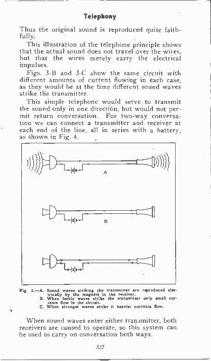
Telephony
Thus the original sound is reproduced quite faith-fully.
This illustration of the telephone principle showsthat the actual sound does not travel over the wires,but that the wires merely carry the electricalimpulses.
Figs. 3-B and 3-C show the same circuit withdifferent amounts of current flowing in each case,as they would be at the time different sound wavesstrike the transmitter.
This simple telephone would serve to transmitthe sound only in one direction, but would not per-mit return conversation. For two-way conversa-tion we can connect a transmitter and receiver ateach end of the line, all in series with a battery,as shown in Fig. 4.
A
B
Fig. 3.-A. Sound waves striking the transmitter are reproduced elec-trically by the magnets in the receiver.
B. When feeble waves strike the transmitter only small cur-rents flow in the circuit.
C. When stronger waves strike it heavier currents flow.
When sound waves enter either transmitter, bothreceivers are caused to operate, so this system canbe used to carry on conversation both ways.
327
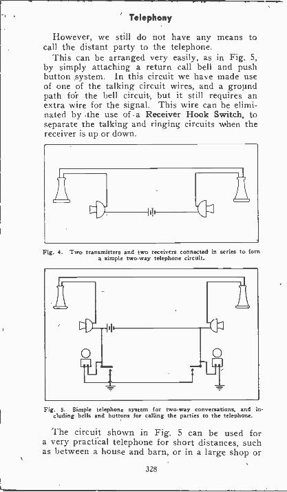
Telephony
However, we still do not have any means tocall the distant party to the telephone.
This can be arranged very easily, as in Fig. 5,by simply attaching a return call bell and pushbutton system. In this circuit we have made useof one of the talking circuit wires, and a groundpath for the hell circuit, but it still requires anextra wire for the signal. This wire can be elimi-nated by .the use of a Receiver Hook Switch, toseparate the talking and ringing circuits when thereceiver is up or down.
Fig. 4. Two transmitters and two receivers connected in series to forna simple two-way telephone circuit.
Fig. 5. Simple telephone system for two-way conversations, and in-cluding bells and buttons for calling the parties to the telephone.
The circuit shown in Fig. 5 can be used fora very practical telephone for short distances, suchas between a house and barn, or in a large shop or
328
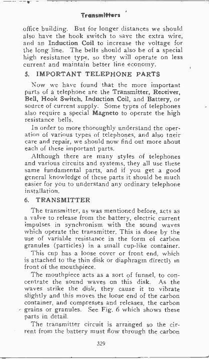
Transmitters
office building. But for longer distances we shouldalso have the hook switch to save the extra wire,and an Induction Coil to increase the voltage forthe long line. The bells should also be of a specialhigh resistance type, so they will operate on lesscurrent and maintain better line economy.5. IMPORTANT TELEPHONE PARTS
Now we have found that the more importantparts of a telephone are the Transmitter, Receiver,Bell, Hook Switch, Induction Coil, and Battery, orsource of current supply. Some types of telephonesalso require a special Magneto to operate the highresistance bells.
In order to more thoroughly understand the oper-ation of various types of telephones, and also tneircare and repair, we should now find out more abouteach of these important parts.
Although there are many styles of telephonesand various circuits and systems, they all use thesesame fundamental parts, and if you get a goodgeneral knowledge of these parts it should be mucheasier for you to understand any ordinary telephoneinstallation.6. TRANSMITTER
The transmitter, as was mentioned before, acts asa valve to release from the battery, electric currentimpulses in synchronism with the sound waveswhich operate the transmitter. This is done by theuse of variable resistance in the form of carbongranules (particles) in a small cup -like container.
This cup has a loose cover or front end, whichis attached to the thin disk or diaphragm directly infront of the mouthpiece.
The mouthpiece acts as a sort of funnel, to con-centrate the sound waves on this disk. As thewaves strike the disk, they cause it to vibrateslightly and this moves the loose end of the carboncontainer, and compresses and releases, the carbongrains or granules. See Fig. 6 which shows theseparts in detail.
The transmitter circuit is arranged so the cir-rent from the battery must flow through the carbon
329
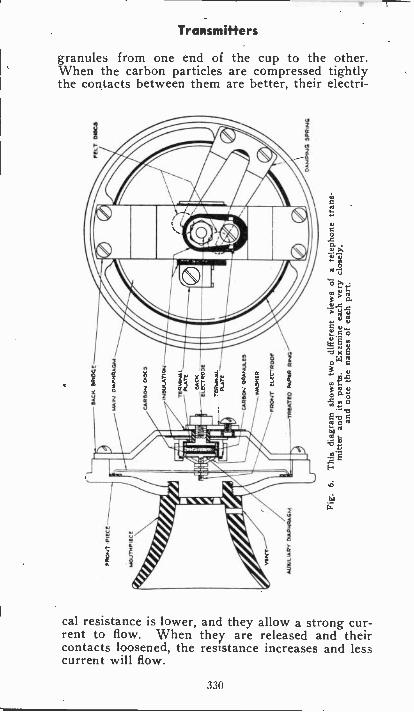
Transmitters
granules from one end of the cup to the other.When the carbon particles are compressed tightlythe contacts between them are better, their electri-
cal resistance is lower, and they allow a strong cur-rent to flow. When they are released and theircontacts loosened, the resistance increases and lesscurrent will flow.
330
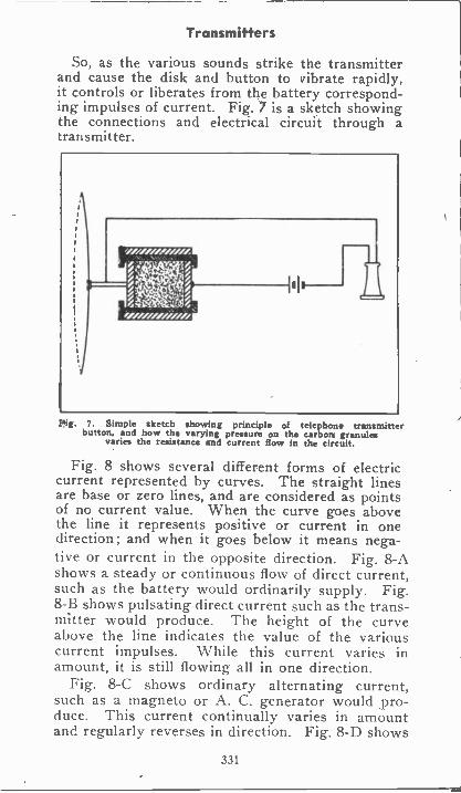
Transmitters
So, as the various sounds strike the transmitterand cause the disk and button to vibrate rapidly,it controls or liberates from the battery correspond-ing impulses of current. Fig. 7 is a sketch showingthe connections and electrical circuit through atransmitter.
Pig. 7. Simple sketch showing principle of telephone transmitterbutton, and how the varying pressure on the carbon granules
varies the resistance and current flow in the circuit.
Fig. 8 shows several different forms of electriccurrent represented by curves. The straight linesare base or zero lines, and are considered as pointsof no current value. When the curve goes abovethe line it represents positive or current in onedirection ; and when it goes below it means nega-tive or current in the opposite direction. Fig. 8-Ashows a steady or continuous flow of direct current,such as the battery would ordinarily supply. Fig.8-B shows pulsating direct current such as the trans-mitter would produce. The height of the curveabove the line indicates the value of the variouscurrent impulses. While this current varies inamount, it is still flowing all in one direction.
Fig. 8-C shows ordinary alternating current,such as a magneto or A. C. generator would pro-duce. This current continually varies in amountand regularly reverses in direction. Fig. 8-D shows
331
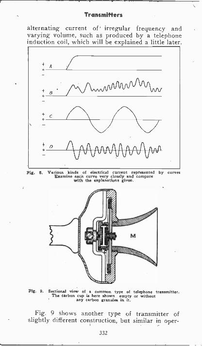
Transmitters
alternating current of irregular frequency andvarying volume, such as produced by a telephoneinduction coil, which will be explained a little later.
Fig. 8. Various kinds of electrical current represented by curvesExamine each curve very closely and compare
with the explanations given.
Fig. 9. Sectional view of a common type of telephone transmitter.The carbon cup is here shown empty or without
any carbon granules in it.
Fig. 9 shows another type of transmitter ofslightly different construction, but similar in oper-
332
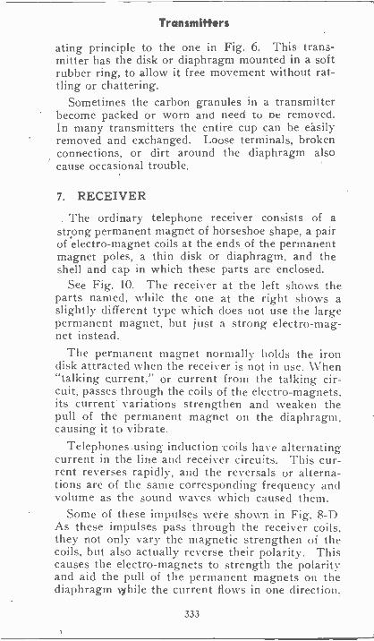
Transmitters
ating principle to the one in Fig. 6. This trans-mitter has the disk or diaphragm mounted in a softrubber ring, to allow it free movement without rat-tling or chattering.
Sometimes the carbon granules in a transmitterbecome packed or worn and need to De removed.In many transmitters the entire cup can be easilyremoved and exchanged. Loose terminals, brokenconnections, or dirt around the diaphragm alsocause occasional trouble.
7. RECEIVER
. The ordinary telephone receiver consists of astrong permanent magnet of horseshoe shape, a pairof electro-magnet coils at the ends of the permanentmagnet poles, a thin disk or diaphragm, and theshell and cap in which these parts are enclosed.
See Fig. 10. The receiver at the left shows theparts named, while the one at the right shows aslightly different type which does not use the largepermanent magnet, but just a strong electro-mag-net instead.
The permanent magnet normally holds the irondisk attracted when the receiver is not in use. When"talking current," or current from the talking cir-cuit, passes through the coils of the electro-magnets,its current variations strengthen and weaken thepull of the permanent magnet on the diaphragm,causing it to vibrate.
Telephones using induction coils have alternatingcurrent in the line and receiver circuits. This cur-rent reverses rapidly, and the reversals or alterna-tions are of the same corresponding frequency andvolume as the sound waves which caused them.
Some of these impulses were shown in Fig. 8-DAs these impulses pass through the receiver coils.they not only vary the magnetic strengthen of thecoils, but also actually reverse their polarity. Thiscauses the electro-magnets to strength the polarityand aid the pull of the permanent magnets on thediaphragm while the current flows in one direction.
333
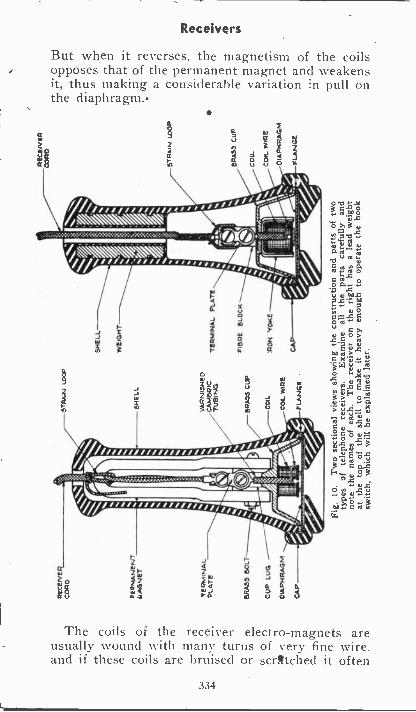
Receivers
But when it reverses, the magnetism of the coilsopposes that of the permanent magnet and weakensit, thus making a considerable variation in pull onthe diaphragm.
3arl
1
//(,, ,,,, , aik/
N\\
g
X V
Ia
The coils of the receiver electro-magnets areusually wound with many turns of very fine wire.and if these coils are bruised or scratched it often
334
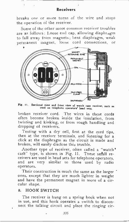
Receivers
breaks one or more turns of the wire and stopsthe operation of the receiver.
Some of the other more common receiver troublesare as follows: Loose end cap, allowing diaphragmto fall away from magnets; bent diaphragm, weakpermanent magnet, loose cord connections, or
CUP
MAGNETRETAHRA/G RING
PE RMANINTMAGNET
COIL.
PCO..E- PIECE
POLE -PILECLAMP
DIAPHRAGM
Fig. 11. Sectional view and front view of watch case receiver, such asused on telephone operators' had sets.
broken receiver cord. The wires in these cordsoften become broken inside the insulation, fromtwisting and kinking, or from rough handling anddropping of receivers.
Testing with a dry cell, first at the cord tips,then at the receiver terminals, and listening for aclick at the diaphragm as the circuit is made andbroken, will easily disclose this trouble.
Another type of receiver, often called a "watch'case" type, is shown in Fig. 11. These sr/fall re-ceivers are used in head sets for telephone operators,and are very similar to those used by radiooperators.
Their construction is much the same as the largerones, except that they are much lighter in weightand have the permanent magnet in more of a cir-cular shape.8. HOOK SWITCH
The receiver is hung on a spring hook when notin use, and this hook operates a switch to discon-nect the talking circuit and place the ringing cir-
335
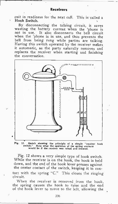
Receivers
suit in readiness for the next call. This is called aHook Switch.
By disconnecting the talking circuit, it saveswasting the battery current when the 'phone isnot in use. It also disconnects the bell circuitwhen the 'phone is in use, and thus prevents thebell from being rung while parties are talking.Having this switch operated by the receiver makesit automatic, as the party naturally removes andreplaces the receiver when starting and finishingthe conversation.
Fig. 12. Sketch showing the principle of a simple "receiver hookswitch." Note what the operation of the spring contacts
would be if the receiver was raised and lowered.
Fig. 12 shows a very simple type of hook switch.While the receiver is on the hook, the hook is helddown, and the end of the hook lever presses againstthe center contact of the switch, keeping it in con-tact with the spring "C." This closes the ringingcircuit.
When the receiver is removed from the hook,the spring causes the hook to raise and the endof the hook lever to move to the left, allowing the
336
Receivers
center spring to make contact with "A" and closethe talking circuit. It also opens the ringing cir-cuit at the same time.
There are a number of different types of hookswitches, but the principle of all of them is verysimilar and easy to understand.
If the contacts of a hook switch become burnedor dirty, or if the contact springs become bent outof shape, it is likely to cause faulty operation ofthe talking and ringing circuits.
9. BATTERIES AND CURRENT SUPPLYTelephones require, for the successful operation
of their talking circuits, direct current supply ofa very "smooth" or constant voltage value. Thisis because we do not want any variations in thecurrent, except those made by the transmitter andsound waves.
In small private telephone systems and rurallines, dry cell batteries are often used, and in manycases each 'phone has its own battery.
Large telephone systems for city service usestorage batteries or D. C. generators for talkingcurrent supply; Generators for this use have specialwindings and commutators for providing "smooth"D. C., as even the slight sparking and variationsof voltage at the commutator of an ordinary powergenerator would produce a disturbing hum in the'phone receivers.
Rural line telephones often use a hand -operatedmagneto to supply current to ring, the bells, andsome small exchanges do also. However, mostexchanges use a generator to produce alternatingcurrent or pulsating direct current, for the operatorsto ring the various parties by merely closing a keyswitch.
10. INDUCTION COILAs mentioned before, most telephones that are
to be used on lines of any great length use aninduction coil. The purpose of this coil is to actlike a transformer and increase the voltage of theimpulses in the talking circuit, so they can he trans -
337
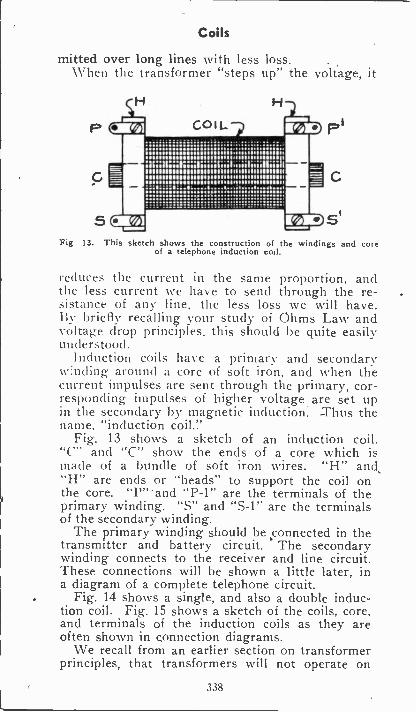
Coils
mitted over long lines with less loss.When the transformer "steps up" the voltage, it
Fig. 13. This sketch shows the construction of the windings and coreof a telephone induction coil.
reduces the current in the same proportion, andthe less current we have to send through the re-sistance of any line, the less loss we will have.By briefly recalling your study of Ohms Law andvoltage drop principles, this should be quite easilyunderstood.
Induction coils have a primary and secondaryW:nding around a core of soft iron, and when thecurrent impulses are sent through the primary, cor-responding impulses of higher voltage are set upin the secondary by magnetic induction. -Thus thename, "induction coil."
Fig. 13 shows a sketch of an induction coil."C" and "C" show the ends of a core which ismade of a bundle of soft iron wires. "H" and,"H" are ends or "heads" to support the coil onthe core. "P"'and "P-1" are the terminals of theprimary winding. "S" and "S-1" are the terminalsof the secondary winding.
The primary winding should be connected in thetransmitter and battery circuit. The secondarywinding connects to the receiver and line circuit.These connections will be shown a little later, ina diagram of a complete telephone circuit.
Fig. 14 shows a single, and also a double induc-tion coil. Fig. 15 shows a sketch of the coils, core,and terminals of the induction coils as they areoften shown in connection diagrams.
We recall from an earlier section on transformerprinciples, that transformers will not operate on
338
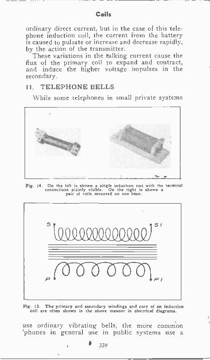
Coils
ordinary direct current, but in the case of this tele-phone induction coil, the current from the batteryis caused to pulsate or increase and decrease rapidly,by the action of the transmitter.
These variations in the talking current cause theflux of the primary coil to expand and contract,and induce the higher votage impulses in thesecondary.
11. TELEPHONE BELLSWhile some telephones in small private systems
:::421111kArt)::'
Fig. 14. On the left is shown a single inauction coil with the terminalconnections plainly visible. On the right is shown a
pair of coils mounted on one base.
$I
01 I II MIII
I P/
Fig. 15. Thd primary and secondary windings and core of an inductioncoil are often shown in the above manner in electrical diagrams.
use ordinary vibrating bells, the more common'phones in general use in public systems use a
339
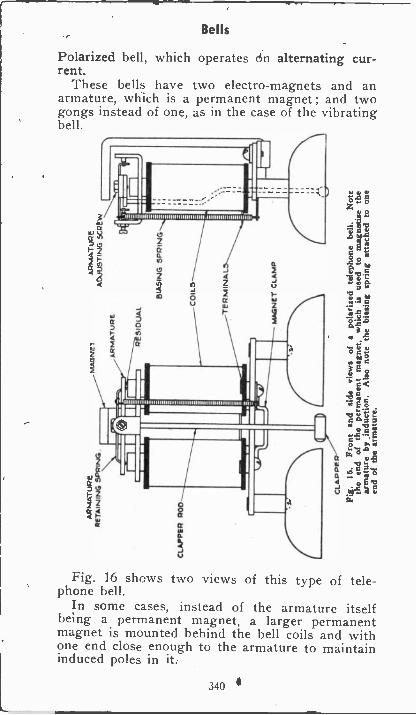
Bells
Polarized bell, which operates do alternating cur-rent.
These bells have two electro-magnets and anarmature, which is a permanent magnet ; and twogongs instead of one, as in the case of the vibratingbell.
8a
rE1111111111111111111111111111111111i1.11,111111111111111111}11111
wQ
2cc4
$0
rai cc
Fig. 16 shows two views of this type of tele-phone bell.
In some cases, instead of the armature itselfbeing a permanent magnet, a larger permanentmagnet is mounted behind the bell coils and withone end close enough to the armature to maintaininduced poles in it.
340
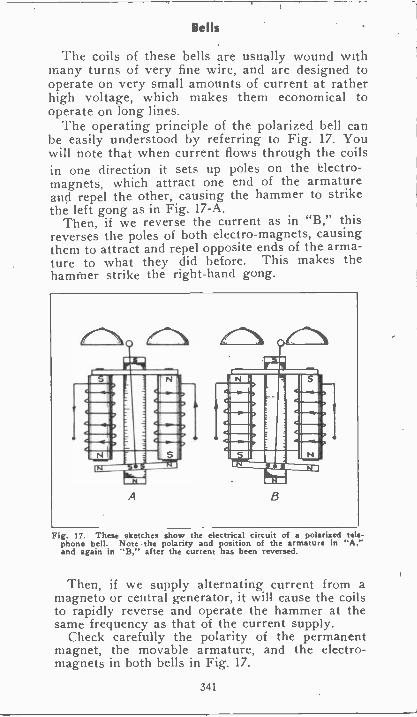
Bells
The coils of these bells are usually wound withmany turns of very fine wire, and are designed tooperate on very small amounts of current at ratherhigh voltage, which makes them economical tooperate on long lines.
The operating principle of the polarized bell canbe easily understood by referring to Fig. 17. Youwill note that when current flows through the coilsin one direction it sets up poles on the electro-magnets. which attract one end of the armatureand repel the other, causing the hammer to strikethe left gong as in Fig. 17-A.
Then, if we reverse the current as in "B," thisreverses the poles of both electro-magnets, causingthem to attract and repel opposite ends of the arma-ture to what they did before. This makes thehammer strike the right-hand gong.
Fig. 17. These sketches show the electrical circuit of a polarized tele-phone bell. Note the polarity and position of the armature in "A,"and again in "B," after the current has been reversed.
Then, if we supply alternating current from amagneto or central generator, it will cause the coilsto rapidly reverse and operate the hammer at thesame frequency as that of the current supply.
Check carefully the polarity of the permanentmagnet, the movable armature, and the electro-magnets in both bells in Fig. 17.
341
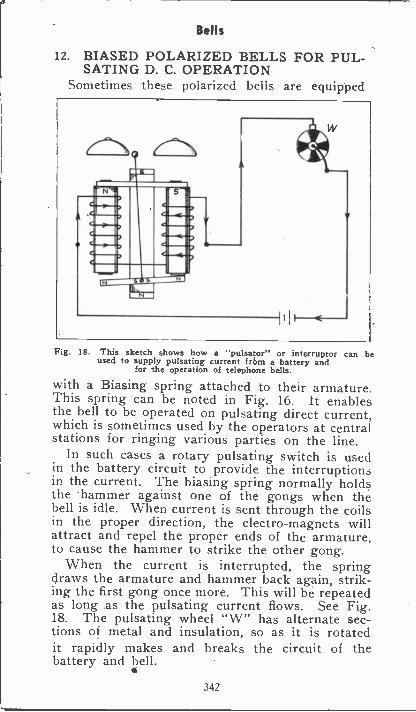
Bells
12. BIASED POLARIZED BELLS FOR PUL-SATING D. C. OPERATION
Sometimes these polarized bells are equipped
iia,.0111' .11.11111 .OPII.1".1111111. .1.1111f..11111. .1111111,11"
.w11' .Mir.11111. .1011'
1,.
Fig. IS. This sketch shows how a "pulsator" or interruptor can beused to supply pulsating current from a battery and
for the operation of telephone bells.
with a Biasing spring attached to their armature.This spring can be noted in Fig. 16. It enablesthe bell to be operated on pulsating direct current,which is sometimes used by the operators at centralstations for ringing various parties on the line.
In such cases a rotary pulsating switch is usedin the battery circuit to provide the interruptionsin the current. The biasing spring normally holdsthe 'hammer against one of the gongs when thebell is idle. When current is sent through the coilsin the proper direction, the electro-magnets willattract and repel the propel' ends of the armature,to cause the hammer to strike the other gong.
When the current is interrupted, the springdraws the armature and hammer back again, strik-ing the first gong once more. This will be repeatedas long as the pulsating current flows. See Fig.18. The pulsating wheel "W" has alternate sec-tions of metal and insulation, so as it is rotatedit rapidly makes and breaks the circuit of thebattery and bell.
342
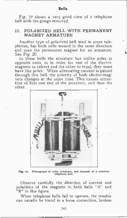
Bells
Fig. 19 shows a very good view of a telephonebell with the gongs removed.
13. POLARIZED BELL WITH PERMANENTMAGNET ARMATURE
Another type of polarized bell used in some tele-phones, has both coils wound in the same directionand uses the permanent magnet for an armature.See Fig. 20.
In these bells the armature has unlike poles atopposite ends, so in order for one of the electro-magnets to attract and the other to repel, they musthave like poles. When alternating current is passedthrough this bell, the polarity of both electromag-nets changes at the same time. This causes attrac-tion of first one end of the armature, and then theother.
Fig. n. Photograph of coils, armature, and hammer of a commontelephone bell.
Observe carefully the direction of current andpolarities of the magnets in both bells "A" and"B" in this figure.
When telephone bells fail to operate, the troublecan usually be found in a loose connection, broken
343
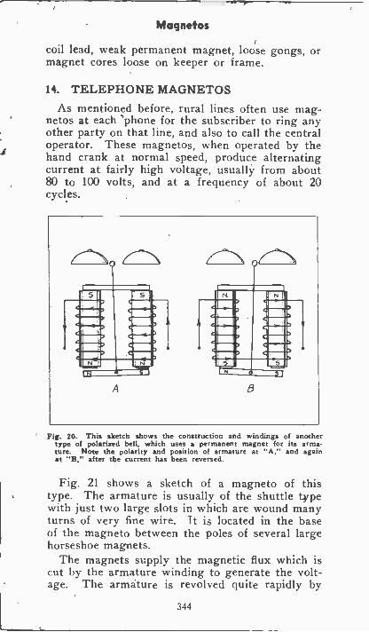
Magnetos
coil lead, weak permanent magnet, loose gongs, ormagnet cores loose on keeper or frame.
14. TELEPHONE MAGNETOSAs mentioned before, rural lines often use mag-
netos at each 'phone for the subscriber to ring anyother party on that line, and also to call the centraloperator. These magnetos, when operated by thehand crank at normal speed, produce alternatingcurrent at fairly high voltage, usually from about80 to 100 volts, and at a frequency of about 20cycles.
A
Fig. 20. This sketch shows the construction and windings of anothertype of polarized bell, which uses a permanent magnet for its arma-ture. Note the polarity and position of armature at "A," and againat "B," after the current has been reversed.
Fig. 21 shows a sketch of a magneto of thistype. The armature is usually of the shuttle typewith just two large slots in which are wound manyturns of very fine wire. It is located in the baseof the magneto between the poles of several largehorseshoe magnets.
The magnets supply the magnetic flux which iscut by the armature winding to generate the volt-age. The armature is revolved quite rapidly by
344
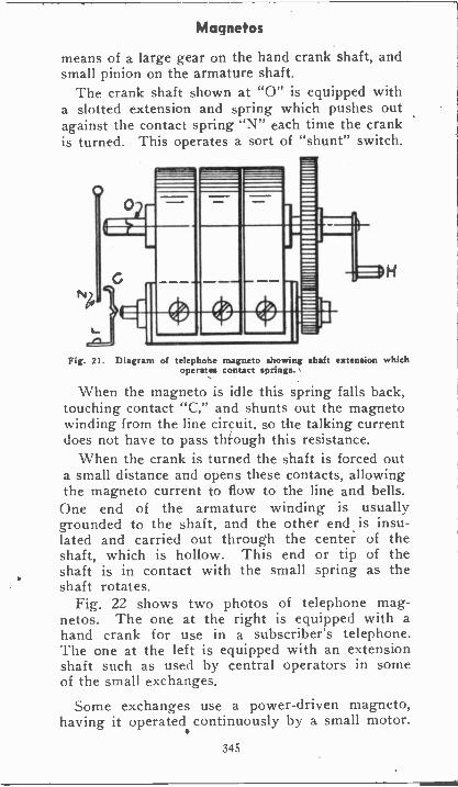
Magnetos
means of a large gear on the hand crank shaft, andsmall pinion on the armature shaft.
The crank shaft shown at "0" is equipped witha slotted extension and spring which pushes outagainst the contact spring "N" each time the crankis turned. This operates a sort of "shunt" switch.
Fig. 21. Diagram of telephone magneto showing shaft extension whichoperates contact springs.
When the magneto is idle this spring falls back,touching contact "C," and shunts out the magnetowinding from the line circuit, so the talking currentdoes not have to pass through this resistance.
When the crank is turned the shaft is forced outa small distance and opens these contacts, allowingthe magneto current to flow to the line and bells.One end of the armature winding is usuallygrounded to the shaft, and the other end is insu-lated and carried out through the center of theshaft, which is hollow. This end or tip of theshaft is in contact with the small spring as theshaft rotates.
Fig. 22 shows two photos of telephone mag-netos. The one at the right is equipped with ahand crank for use in a subscriber's telephone.The one at the left is equipped with an extensionshaft such as used by central operators in someof the small exchanges.
Some exchanges use a power -driven magneto,having it operated continuously by a small motor.
345
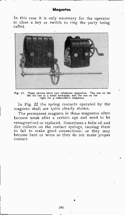
Magnetos
In this case it is only necessary for the operatorto close a key or switch to ring the party beingcalled.
Fig. 22. These photos show two telephone magnetos. The one on theleft for use in a small exchange, and the one on the
right for a subscriber's telephone.
In Fig. 22 the spring contacts operated by themagneto shaft are quite clearly shown.
The permanent magnets in these magnetos oftenbecome weak after a certain age and need to beremagnetized or replaced. Sometimes a little oil anddirt collects on the contact springs, causing themto fail to make good connections ; or they maybecome bent or worn so they do not make propercontact.
346
Magnetos
EXPERIMENTS
A simple experiment to prove the operating prin-ciple of the telephone may be performed as shownby Fig. 3. This experiment requires only one trans-mitter and one receiver, but if you have an addi-tional telephone or Radio receiver and an extratransmitter you will find the jobs suggested by Figs.,4 and 5 to be very interesting.
EXAMINATION QUESTIONS
1. What is the frequency range of audiblesound?
2. At what speed do sound waves travel?3. At what speed does electricity travel?4. What kind of bells are usually used on tele-
phones? Why?5. What kind of current does the telephone mag-
neto supply ?
6. For what purpose is the magneto current usedon a telephone?
7. Why are induction coils used in telephones?8. What kind of current should be used in the
talking circuit?9. Name two important parts of the transmitter.10. What happens to the resistance of the tele-
phone circuit when sound waves strike the dia-phragm of the transmitter?
347
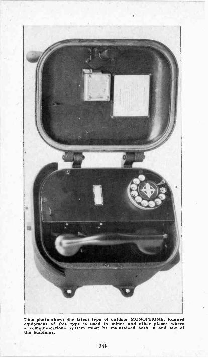
This photo shows the latest type of outdoor MONOPHONE. Ruggedequipment of this type is used in mines and other places wherea communications system must be maintained both in and out ofthe buildings.
348
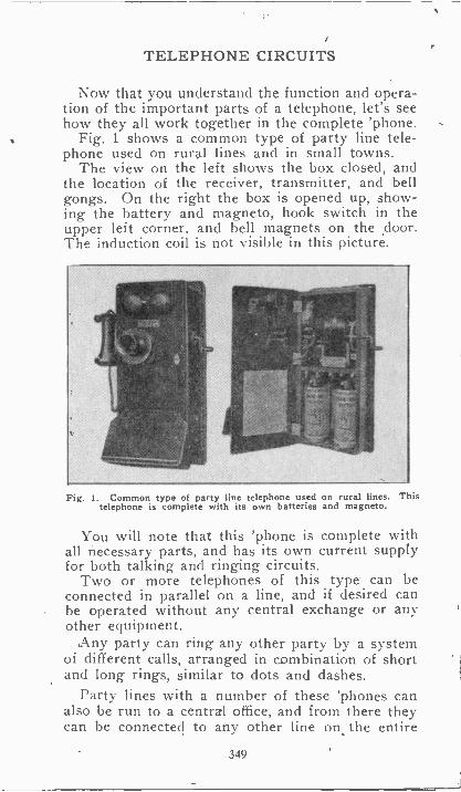
TELEPHONE CIRCUITS
Now that you understand the function and opera-tion of the important parts of a telephone, let's seehow they all work together in the complete 'phone.
Fig. 1 shows a common type of party line tele-phone used on rural lines and in small towns.
The view on the left shows the box closed, andthe location of the receiver, transmitter, and bellgongs. On the right the box is opened up, show-ing the battery and magneto, hook switch in theupper left corner, and bell magnets on the .door.The induction coil is not visible in this picture.
Fig. 1. Common type of party line telephone used on rural lines. Thistelephone is complete with its own batteries and magneto.
You will note that this 'phone is complete withall necessary parts, and has its own current supplyfor both talking and ringing circuits.
Two or more telephones of this type can beconnected in parallel on a line, and if desired canbe operated without any central exchange or anyother equipment.
Any party can ring any other party by a systemof different calls, arranged in combination of shortand long rings, similar to dots and dashes.
Party lines with a number of these 'phones canalso be run to a central office, and from there theycan be connected to any other line on. the entire
349
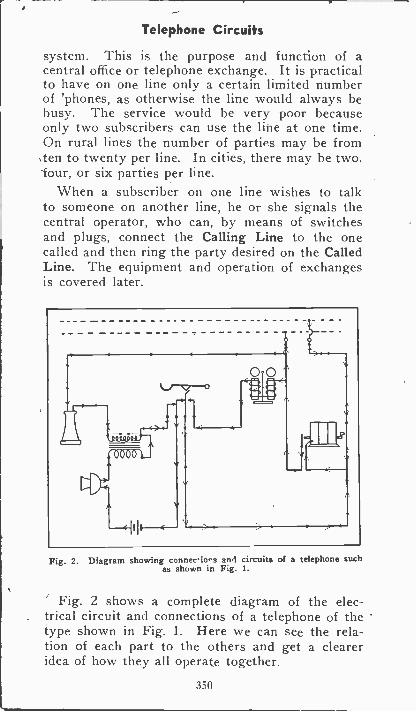
Telephone Circuits
system. This is the purpose and function of acentral office or telephone exchange. It is practicalto have on one line only a certain limited numberof 'phones, as otherwise the line would always bebusy. The service would be very poor becauseonly two subscribers can use the line at one time.On rural lines the number of parties may be from
,ten to twenty per line. In cities, there may be two,lour, or six parties per line.
When a subscriber on one line wishes to talkto someone on another line, he or she signals thecentral operator, who can, by means of switchesand plugs, connect the Calling Line to the onecalled and then ring the party desired on the CalledLine. The equipment and operation of exchangesis covered later.
0 0
Fig. 2. Diagram showing conneviova an4 circuits of a telephone suchas shown in Fig. 1.
Fig. 2 shows a complete diagram of the elec-trical circuit and connections of a telephone of thetype shown in Fig. 1. Here we can see the rela-tion of each part to the others and get a cleareridea of how they all operate together.
350
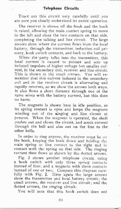
Telephone Circuits
Trace out this circuit very carefully until youare sure you clearly understand its entire operation.
The receiver is shown off the hook and the hookis raised, allowing the main contact spring to moveto the left and close the two contacts on that side,completing the talking and line circuit. The largearrows show where the current flows from the localbattery, through the transmitter, induction coil pri-mary, hook switch contacts, and back to the battery.
When the 'party talks into the transmitter, thislocal current is caused to pulsate and sets upinduced impulses of higher voltage but smaller cur-rent, in the secondary coil, receiver and line circuit.This is shown in the small arrows. You will re-member that this current induced in the secondarycoil and in the receiver circuit is alternating andrapidly reverses, so we show the arrows both ways.It also flows a short distance through one of thesame wires with the battery current, but this doesno harm.
The magneto is shown here in idle position, soits spring contact is open and keeps the magnetowinding out of the ringing and line circuit atpresent. When the magneto is operated, the shaftpushes out and closes the circuit, and sends currentthrough the bell and also out on the line to theother bells.
In order to ring anyone, the receiver must be onthe hook, keeping the hook down and holding themain spring or line contact to the right and incontact with the spring on that side. The ringingcurrent then flows as shown by the dotted arrows.
Fig. 3 shows another telephone circuit, usinga hook switch with only three spring contactsinstead of four, and a magneto with three contactsinstead of one or two. Compare this diagram care-fully with Fig. 2. Here again the large arrowsshow the transmitter and local battery circuit ; thesmall arrows, the receiver and line circuit; and thedotted arrows, the ringing circuit.
You will note that this hook switch does not
351
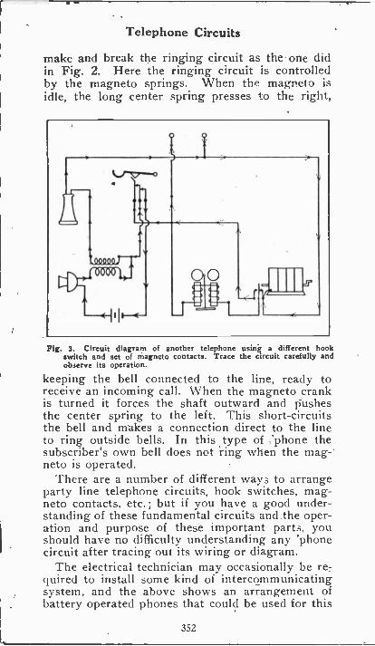
Telephone Circuits
make and break the ringing circuit as the one didin Fig. 2. Here the ringing circuit is controlledby the magneto springs. When the magneto isidle, the long center spring presses to the right,
Fig. 3. Circuit diagram of another telephone using a different hookswitch and set of magneto contacts. Trace the circuit carefully andobserve its operation.
keeping the bell connected to the line, ready toreceive an incoming call. When the magneto crankis turned it forces the shaft outward and pushesthe center spring to the left. This short-circuitsthe bell and makes a connection direct to the lineto ring outside bells. In this type of :phone thesubscriber's own bell does not ring when the mag-'neto is operated.
There are a number of different ways to arrangeparty line telephone circuits, hook switches, mag-neto contacts, etc. ; but if you have a good under-standing of these fundamental circuits and the oper-ation and purpose of these important parts, youshould have no difficulty understanding any 'phonecircuit after tracing out its wiring or diagram.
The electrical technician may occasionally be re-quired to install some kind of intercommunicatingsystem, and the above shows an arrangement ofbattery operated phones that could be used for this
352
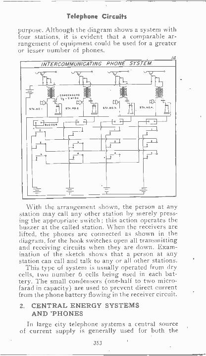
Telephone Circuits
purpose. Although the diagram shows a system withfour stations, it is evident that a comparable ar-rangement of equipment could be used for a greateror lesser number of phones.
/4INTERCOMMUNICATING PHONE SYSTEM
-t
T
_1
4
-r
With the arrangement shown, the person at anystation may call any other station by merely press-ing the appropriate switch ; this action operates thebuzzer at the called station. When the receivers arelifted, the phones are connected as shown in thediagram, for the hook switches open all transmittingand receiving circuits when they are down. Exam-ination of the sketch shows that a person at anystation can call and talk to any or all other stations.
This type of system is usually operated from drycells, two number 6 cells being used in each bat-tery. The small condensers (one-half to two micro -farad in capacity) are used to prevent direct currentfrom the phone battery flowing in the receiver circuit.
2. CENTRAL ENERGY SYSTEMSAND 'PHONES
In large city telephone systems a central sourceof current supply is generally used for both the
353
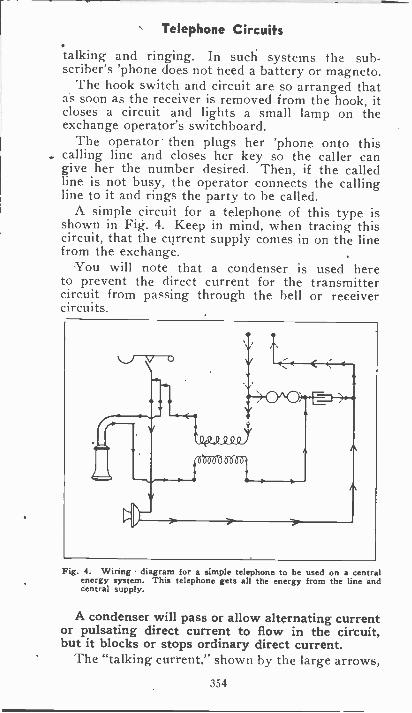
Telephone Circuits
talking and ringing. In such systems the sub-scriber's 'phone does not need a battery or magneto.
The hook switch and circuit are so arranged thatas soon as the receiver is removed from the hook, itcloses a circuit and lights a small lamp on theexchange operator's switchboard.
The operator- then plugs her 'phone onto thiscalling line and closes her key so the caller cangive her the number desired. Then, if the calledline is not busy, the operator connects the callingline to it and rings the party to be called.
A simple circuit for a telephone of this type isshown in Fig. 4. Keep in mind, when tracing thiscircuit, that the current supply comes in on the linefrom the exchange.
You will note that a condenser is used hereto prevent the direct current for the transmittercircuit from passing through the bell or receivercircuits.
V (-)
V
\w'
< 4
H0^0,44P.E.--<
Wi 0 Yfeboot old o
A
Fig. 4. Wiring diagram for a simple telephone to be used on a centralenergy system. This telephone gets all the energy from the line andcentral supply.
A condenser will pass or allow alternating currentor pulsating direct current to flow in the circuit,but it blocks or stops ordinary direct current.
The "talking current." shown by the large arrows,
354
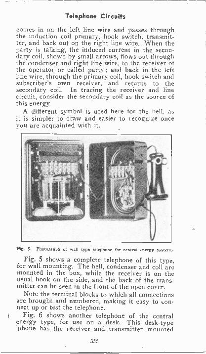
Telephone Circuits
comes in on the left line wire and passes throughthe induction coil primary, hook switch, transmit-ter, and back out on the right line wire. When theparty is talking, the induced current in the secon-dary coil, shown by small arrows, flows out throughthe condenser and right line wire, to the receiver ofthe operator or called party ; and back in the leftline wire, through the primary coil, hook switch andsubscriber's own receiver, and returns to thesecondary coil. In tracing the receiver and linecircuit, consider the secondary coil as the source ofthis energy.
A different symbol is used here for the bell, asit is simpler to draw and easier to recognize onceyou are acquainted with it.
Fig. S. Photograph of wall type telephone for central energy systems.
Fig. 5 shows a complete telephone of this type,for wall mounting. The bell, condenser and coil aremounted in the box, while the receiver is on theusual hook on the side, and the back of the trans-mitter can be seen in the front of the open cover.
Note the terminal blocks to which all connectionsare brought and numbered, making it easy to t.on-nect up or test the telephone.
Fig. 6 shows another telephone of the centralenergy type, for use on a desk. This desk -type'phone has the receiver and transmitter mounted
355
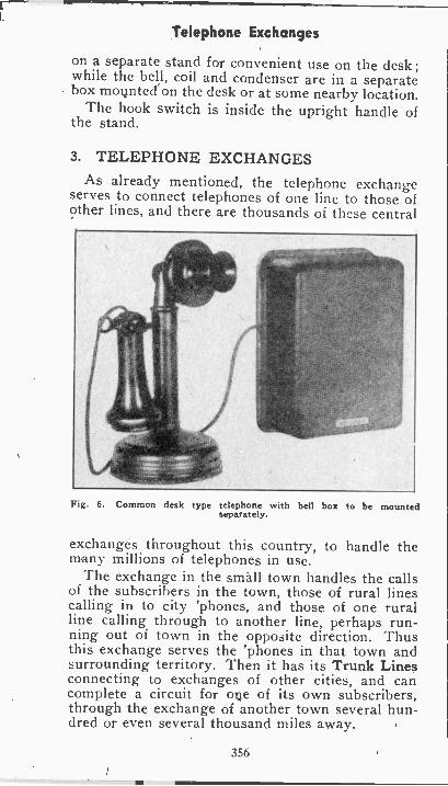
Telephone Exchanges
on a separate stand for convenient use on the desk ;while the bell, coil and condenser are in a separatebox movnted on the desk or at some nearby location.
The hook switch is inside the upright handle ofthe stand.
3. TELEPHONE EXCHANGESAs already mentioned, the telephone exchange
serves to connect telephones of one line to those ofother lines, and there are thousands of these central
Fig. 6. Common desk type telephone with bell box to be mountedseparately.
exchanges throughout this country, to handle themany millions of telephones in use.
The exchange in the small town handles the callsof the subscribers in the town, those of rural linescalling in to city 'phones, and those of one ruralline calling through to another line, perhaps run-ning out of town in the opposite direction. Thusthis exchange serves the 'phones in that town andsurrounding territory. Then it has its Trunk Linesconnecting to exchanges of other cities, and cancomplete a circuit for me of its own subscribers,through the exchange of another town several hun-dred or even several thousand miles away.
356
Telephone Exchanges
This vast network requires many types of elabo-rate exchange circuits, which it is not our purposeto cover here, as they represent a very highlyspecialized type of work. They also require muchmore time than the average electrician cares tospend on such circuits, unless he intends to spe-cialize in telephone work. But, in order to giveyou a better understanding of the general operationof the exchange in connection with the 'phoneswe all use daily, and also to give you a good foun-dation to work from in case you should later speci-alize in such work, we will cover in the followingmaterial some of the fundamental parts and prin-ciples of exchanges.
Telephone exchanges are of two general types,namely, manual and automatic.
The general function of either type is to receivea signal from the calling subscriber, and get a con-nection and ring his party on any other line asquickly as possible.
With the manual exchange, the plugging, switch-ing and ringing operations are performed by humanoperators, usually girls. With the automatic ex-change these operations are performed by electricaland mechanical equipment.
4. SWITCHBOARDS FOR MANUALOPERATION
Fig. 7 shows a manual exchange or switch-board, for handling one hundred lines. These linesare brought up to Jacks on the upright part of theboard.
On the flat, desk -like, part of the board is a set ofPlugs, attached to Cords beneath, and also a set ofKey Switches. Directly above each jack is a Dropsimilar to an annunciator drop.
When a subscriber on any line signals the oper-ator, the little drop window or shutter for his linefalls down, showing the operator that someone onthat line is calling. There are two plugs in front ofthat line, one for talking and one for ringing.
The operator lifts the talking plug and inserts itin the line jack opening. Then, by pressing herkey in one direction, she can answer the Calling
357
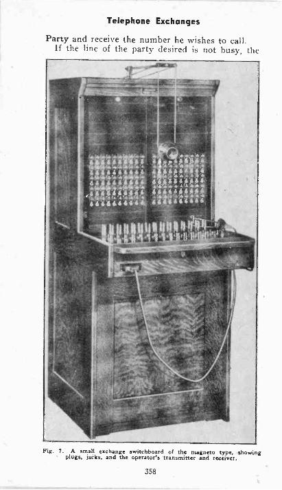
Telephone Exchanges
Party and receive the number he wishes to call.If the line of the party desired is not busy, the
Ait 4 /1 4
*:4 a 4'd WE,
A 4AA'sktiA:441,414:
Fig. 7. A small exchange switchboard of the magneto type, showingplugs, jacks, and the operator's transmitter and receiver.
358
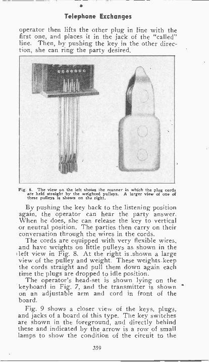
Telephone Exchanges
operator then lifts the other plug in line with thefirst one, and places it in the jack of the "called"line. Then, by pushing the key in the other direc-tion, she can ring the party desired.
Fig. 8. The view on the left shows the manner in which the plug cordsare held straight by the weighted pulleys. A larger view of one ofthese pulleys is shown on the right.
By pushing the key back to the listening positionagain, the operator can hear the party answer.When he does, she can release the key to verticalor neutral position. The parties then carry on theirconversation through the wires in the cords.
The cords are equipped with very flexible wires,and have weights on little pulleys as shown in theleft view in Fig. 8. At the right is .shown a largeview of the pulley and weight. These weights keepthe cords straight and pull them down again eachtime the plugs are dropped to idle position.
The operator's head -set is shown lying on thekeyboard in Fig. 7, and the transmitter is shownon an adjustable arm and cord in front of theboard.
Fig. 9 shows a closer view of the keys, plugs,and jacks of a board of this type. The key switchesare shown in the foreground, and directly behindthese and indicated by the arrow is a row of smalllamps to show the condition of the circuit to the
a
359
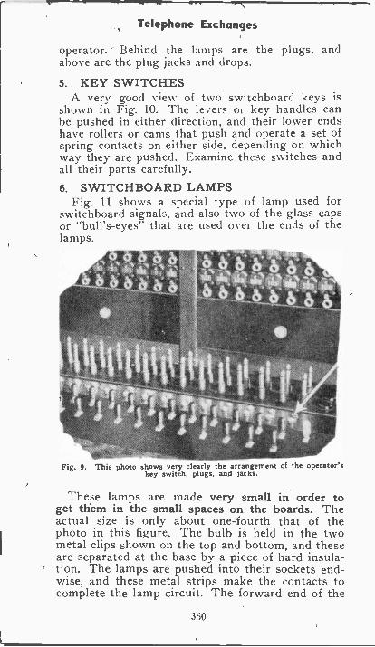
Telephone Exchanges
operator. Behind the lamps are the plugs, andabove are the plug jacks and drops.
5. KEY SWITCHESA very good view of two switchboard keys is
shown in Fig. 10. The levers or key handles canbe pushed in either direction, and their lower endshave rollers or cams that push and operate a set ofspring contacts on either side, depending on whichway they are pushed. Examine these switches andall their parts carefully.6. SWITCHBOARD LAMPS
Fig. 11 shows a special type of lamp used forswitchboard signals, and also two of the glass capsor "bull's-eyes" that are used over the ends of thelamps.
Fig. 9. This photo shows very clearly the arrangement of the operator'skey switch, plugs, and jacks.
These lamps are made very small in order toget them in the small spaces on the boards. Theactual size is only about one-fourth that of thephoto in this figure. The bulb is held in the twometal clips shown on the top and bottom, and theseare separated at the base by a piece of hard insula-tion. The lamps are pushed into their sockets end-wise, and these metal strips make the contacts tocomplete the lamp circuit. The forward end of the
360
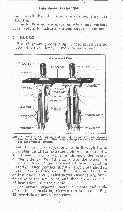
Telephone Exchanges
lamp is all that shows in the opening they areplaced in.
The bull's-eyes are made in white and variousother colors to indicate various circuit conditions.
7. PLUGS
Fig. 13 shows a cord plug. These plugs can bemade with two, three, or more separate metal ele-
Switchboard Keys
L.13.51111 ,,,11 I 111110.3
CO.1..1 IN OW
.
h
I I. gittlifF
Fig. 10. Here we have an excellent view of two key switches, showinghow the key levers and rollers operate the spring contacts, and openand close various circuits.
ments for as many separate circuits through them.The plug tip at the extreme right end is part of asmall metal rod which runs through the centerof the plug to the left end, where the wires areattached. Around this is placed a tube of insulatingmaterial. Then another slightly larger, but shorter,metal sleve is fitted over this. Still another tubeof insulation, and a third metal element are oftenfitted over the first ones, and then an outer shellof insulation over the whole.
The several separate metal elements and endsof the black insulating sleeves can be seen in Fig.13, which is an actual size view.
361
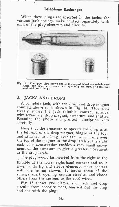
Telephone Exchanges
When these plugs are inserted in the jacks, thevarious jack springs make contact separately witheach of the plug elements and circuits.
Fig. 11. The upper view shows one of the special telephone switchboardlamps, and below are shown two types of glass caps, or bull's-eyesused with such lamps.
8. JACKS AND DROPSA complete jack, with the drop and drop magnet
counted above it, is shown in Fig. 14. This viewclearly shows the jack thimble, contact springs,wire terminals, drop magnet, armature, and shutter.Examine the photo and printed description verycarefully.
Note that the armature to operate the drop is atthe left end of the drop magnet, hinged at the top,and attached to a long lever arm which runs overthe top of the magnet to the drop latch at the rightend. This construction enables a very small move-ment of the armature to give a greater movementat the drop latch.
The plug would be inserted from the right in thethimble at the lower right-hand corner ; and as itgoes in, its tip and sleeve elements make contactwith the spring shown. It forces some of thesprings apart, opening certain circuits, and closesothers from the springs to the cord wires.
Fig. 15 shows two diagrams of jack and dropcircuits from opposite sides, one without the plugand one with the plug.
362
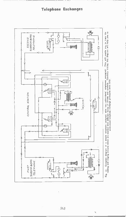
F/H
5TS
UB
SC
RIB
ER
ST
ELE
PH
ON
E
:x .4
,111
111-
L
A
CE
NT
RA
LS
TA
TIO
N
thr
7714
1I 1
11N
,
SE
CO
ND
SU
BS
CR
IBE
RS
TE
LEP
HO
NE
-r-r
rn--
-1(4
1el
Fig
.12
.C
ompl
ete
diag
ram
of
asi
mpl
e te
leph
one
exch
ange
with
two
subs
crib
ers'
tele
phon
es c
onne
cted
.T
his
will
ena
ble
you
to tr
ace
the
talk
ing
and
ringi
ng c
ircui
ts w
hich
are
mar
ked
with
diff
eren
t for
ms
of a
rrow
s an
d sy
mbo
ls.
Car
eful
ly tr
acin
g th
is d
iagr
am w
ill h
elp
you
toun
ders
tand
tele
phon
e ex
chan
ge p
rinci
ples
mor
e fu
lly.
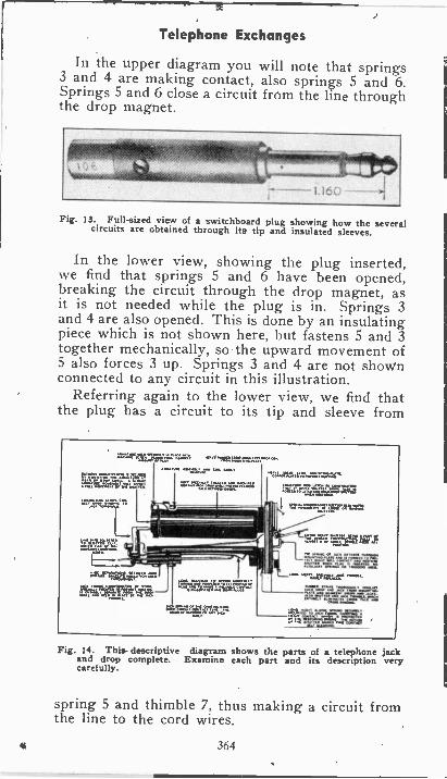
I ::`,..=.7,77erg:=1
Telephone Exchanges
In the upper diagram you will note that springs3 and 4 are making contact, also springs 5 and 6.Springs 5 and 6 close a circuit from the line throughthe drop magnet.
Fig. 13. Full-sized view of a switchboard plug showing how the severalcircuits are obtained through its tip and insulated sleeves.
In the lower view, showing the plug inserted,we find that springs 5 and 6 have been opened,breaking the circuit through the drop magnet, asit is not needed while the plug is in. Springs 3and 4 are also opened. This is done by an insulatingpiece which is not shown here, but fastens 5 and 3together mechanically, so the upward movement of5 also forces 3 up. Springs 3 and 4 are not shownconnected to any circuit in this illustration.
Referring again to the lower view, we find thatthe plug has a circuit to its tip and sleeve from
..":4.74":8A'51illaFT:=1 ...=jzzgrap,....
trniptgartr.a.r=2.1
9.614E2firagi
Fig. 14. This- descriptive diagram shows the parts of a telephone jackand drop complete. Examine each part and its description verycarefully.
spring 5 and thimble 7, thus making a circuit fromthe line to the cord wires.
364
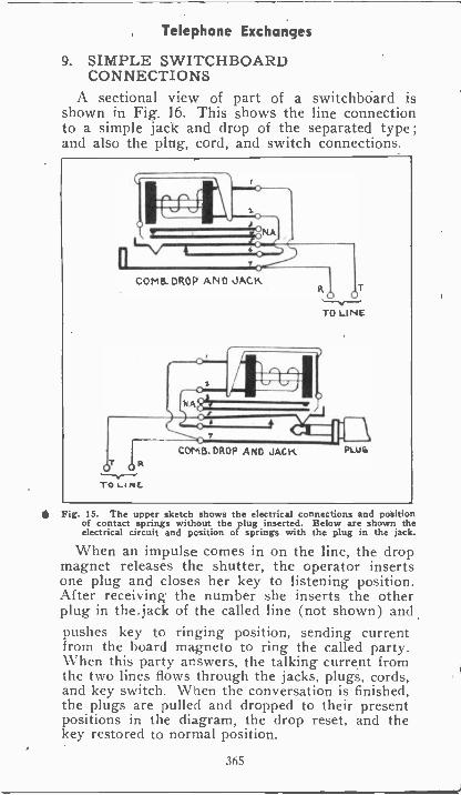
Telephone Exchanges
9. SIMPLE SWITCHBOARDCONNECTIONS
A sectional view of part of a switchboard isshown in Fig. l6. This shows the line connectionto a simple jack and drop of the separated type ;and also the plug, cord, and switch connections.
Fig. 15. The upper sketch shows the electrical connections and positionof contact springs without the plug inserted. Below are shown theelectrical circuit and position of springs with the plug in the jack.
When an impulse comes in on the line, the dropmagnet releases the shutter, the operator insertsone plug and closes her key to listening position.After receiving the number she inserts the otherplug in the.jack of the called line (not shown) andpushes key to ringing position, sending currentfrom the board magneto to ring the called party.When this party answers, the talking current fromthe two lines flows through the jacks, plugs, cords,and key switch. When the conversation is finished,the plugs are pulled and dropped to their presentpositions in the diagram, the drop reset, and thekey restored to normal position.
365
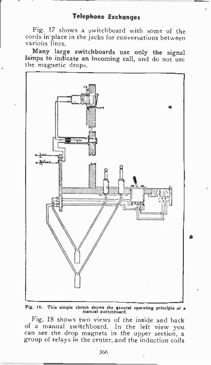
Telephone Exchanges
Fig. 17 shows a switchboard with some of thecords in place in the jacks for conversations betweenvarious lines.
Many large switchboards use only the signallamps to indicate an incoming call, and do not usethe magnetic drops.
Fig. 16. This simple sketch shows the general operating principle of amanual switchboard.
Fig. 18 shows two views of the inside and backof a manual switchboard. In the left view youcan see the drop magnets in the upper section, agroup of relays in the center, and the induction coils
366
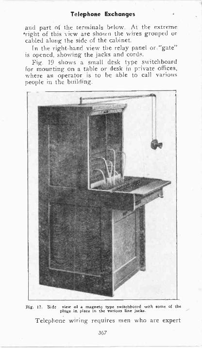
Telephone Exchanges
and part of the terminals below. At the extremeright of this view are shown the wires grouped orcabled along the side of the cabinet.
In the right-hand view the relay panel or: "gate"is opened, showing the jacks and cords.
Fig. 19 shows a small desk type switchboardfor mounting on a table or desk in private offices,where au operator is to he able to call variouspeople in the building.
Flig. 17. Side view of a magneto type switchboard with some of theplugs in place in the various line jacks.
Telephone wiring requires men who are expert
367
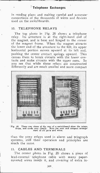
Telephone Exchanges
in reading plans and making careful and accurateconnections of the thousands of wires and devicesused on the switchboards.
10. TELEPHONE RELAYSThe top photo in Fig. 20 shows a telephone
relay. Its armature is at the right-hand end ofthe magnet, and is bent and hinged to the cornerof the magnet frame. When the magnet attractsthe lower end of the armature to the left, its upperhorizontal portion moves upward at its left end,pushing the center contact springs upward. Thiscauses them to break circuits with the lower con-tacts and make circuits with the upper ones. Soyou see that while these relays are constructeddifferently and are much smaller and more compact
Fig. 18. These two views of the rear of a switchboard show the relays,drops, and cords very clearly. Note the neat and compact arrange-
ment of all parts and wires.
than the pony relays used in alarm and telegraphsystems, still their operation and principles aremuch the same.
11. CABLES AND TERMINALSThe center photo in Fig. 20 shows a piece of
lead -covered telephone cable with many paper -covered wires inside it, and covering of extra in -
368
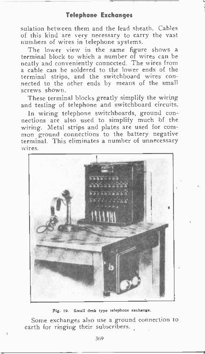
Telephone Exchanges
sulation between them and the lead sheath. Cablesof this kind are very necessary to carry the vastnumbers of wires in telephone systems.
The lower view in the same figure shows aterminal block to which a number of wires can beneatly and conveniently connected. The wires froma cable can be soldered to the lower ends of theterminal strips, and the switchboard wires con-nected to the other ends by means of the smallscrews shown.
These terminal blocks greatly simplify the wiringand testing of telephone and switchboard circuits.
In wiring telephone switchboards, ground con-nections are also used to simplify much bf thewiring. Metal strips and plates are used for com-mon ground connections to the battery negativeterminal. This eliminates a number of unnecessarywires.
Fig. 19. Small desk type telephone exchange.
Some exchanges also use a ground connection toearth for ringing their subscribers.
369
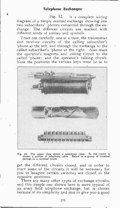
Telephone Exchanges
Fig. 12, is a complete wiringdiagram of a simple manual exchange showing justtwo subscribers' 'phones connected through the ex-change. The different circuits are marked withdifferent kinds of arrows and symbols.
Trace out carefully, one at a time, the transmitterand receiver circuits of the calling subscriber's'phone at the left, and through the exchange to thecalled subscriber's 'phone at the right. Also tracethe operator's magneto and calling circuit to thecalled 'phone ; and the operator's talking circuit.Note the positions the various keys must be in to
run writ wr-
Fig. 20. The upper view shows a telephone relay. In the center isshown a section of telephone cable. Below is a group of terminalsprings in a terminal block.
get the different circuits closed, and in order totrace some of the circuits it will be necessary foryou to imagine certain switches are closed to theopposite positions.
There are many other types of exchange circuits,and this simple one shown here is more typical ofan army field telephone exchange, but is chosenbecause of its simplicity and just to give you a good
370
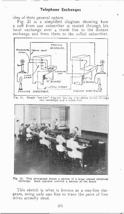
Telephone Exchanges
idea of their general nature.Fig. 21 is a simplified diagram showing how
a call from one subscriber is routed through hislocal exchange over a trunk line to the distantexchange and from there to the called subscriber
ANSWER/N6 rowmfa TACK_TACK
L/NeLAMP
TRUNKMANUA L
BoAgo
CALL/NG SLOSCR/BeR. CALLE() .56/115,4,04-14.
Fig. 21. Sim?le "one -line" d.agrain dio..ing a te.:phone ci.cuit throughtwo exchanges a:A a trunk line.
Fig. 22. This photograph shows a section of a large manual telephoneexchange. Each operator controls a section of the board
This sketch is what is known as a one -line dia-gram, using only one line to trace the pairs of linewires actually used.
371
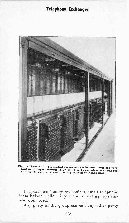
Telephone Exchanges
Fig. 23. Rear view of a central exchange switchboard. Note the veryneat and compact manner in which all parts and wires are arrangedto simplify connections and testing of such exchange units.
In apartment houses and offices, small telephoneinstallations called inter -communicating systemsare often used.
Any party of the group can call any other party
372
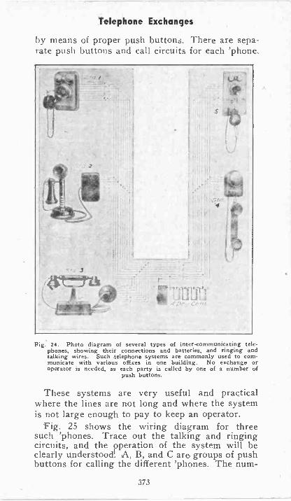
Telephone Exchanges
by means of proper push buttons. There are sepa-rate push buttons and call circuits for each 'phone.
Fig. 24. Photo diagram of several types of inter -communicating to e -phones, showing their connections and batteries, and ringing andtalking wires. Such telephone systems are commonly used to com-municate with various offices in one building. No exchange oroperator is needed, as each party is called by one of a number of
push buttons.
These systems are very useful and practicalwhere the lines are not long and where the systemis not large enough to pay to keep an operator.
Fig. 25 shows the wiring diagram for threesuch 'phones. Trace out the talking and ringingcircuits, and the operation of the system will beclearly understood! A, B, and C are groups of pushbuttons for calling the different 'phones. The num-
373
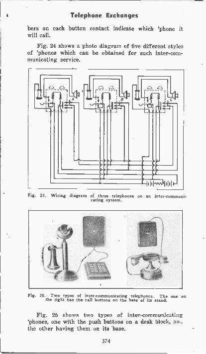
a Telephone Exchanges
bers on each button contact indicate which 'phone itwill call.
Fig. 24 shows a photo diagram of five different stylesof 'phones which can be obtained for such inter -com-municating service.
L_ LR
It"
_1
-1110^4 I I
Fig. 25. Wiring diagram of three telephones on an inter -communi-cating system.
Fig. 26. Two types of inter -communicating telephones. The one onthe right has the call buttons on the base of its stand.
Fig. 26 shows two types of inter -communicating'phones, one with the push buttons on a desk block, au_theother having them on its base.
374
EXAMINATION QUESTIONS
1-Name the six important parts of a telephonesuch as used on a rural party line.
2-Will the bell shown in Fig. 2, ring when thereceiver is off the hook? Why?
3-Are batteries used on each subscribers' tele-phone in City systems?
4-What kind of a bell is shown in Fig. 3?5-Referring to Figs. 2 and 3, what piece of
electrical equipment do you find is used in supplyingthe bell ringing current?
6-Where-is the power supply located for oper-ating a telephone such as shown by Fig. 4?
7-What kind of current will a condenser allowto flow in a circuit. (b) What kind of current willa condenser stop?
8-Why are telephone switch -board lamps smalland slender?
9-Do all telephone switch -boards use magneticdrops?
10-What is the purpose or advantage of tele-phone terminal blocks?
375
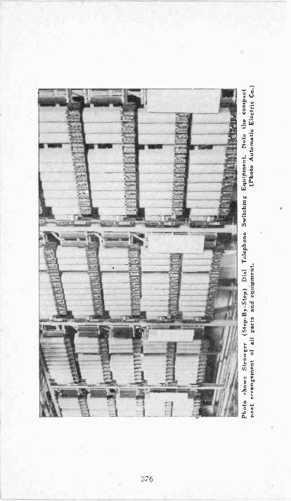
Pho
to s
how
s S
trow
ger
(Ste
p. B
y -S
tep)
Dia
lT
elep
hone
Sw
itchi
ng E
quip
men
t.N
ote
the
com
pact
neat
arr
ange
men
t of a
llpa
rts
and
equi
pmen
t.(P
hoto
Aut
omat
ic E
lect
ric C
o.)
AUTOMATIC TELEPHONES
Automatic exchanges do all switching, ringing,and signaling by means cf electrical and mechan-ical equipment. This not only saves the cost oflabor of numerous operators, but accomplishesfaster and more accurate operation. It providesmuch more complete privacy for telephone conver-sations, and, because it is purely electrical and me-chanical, the possibility of human errors is largelyeliminated.
The automatic telephone exchange is undoubted-ly one of the greatest triumphs of telephone en-gineering, and they are rapidly replacing manyof the largest manual exchanges in this country.
There are several different types of automatictelephone equipment, and most of them are stillundergoing rapid changes in the processes of devel-opment and perfection. One of the most successfulsystems is call the "Strowger System," after theman who developed it.
Complete automatic exchange circuits require agreat deal more time and study than most studentswould care to spend on the subject, unless theywere preparing to specialize in this work. The fun-damental principles of this equipment, however, canbe quite simply explained.
The following paragraphs are intended to giveyou a good understanding of automatic telephones.
1. SIMPLE OPERATING PRINCIPLE
The Strowger System uses what is known as the"step by step" equipment. When the subscriberwishes to call a certain party, he dials the desirednumber with the dial on his own telephone. Thisdial in its rotation sends a number of impulsestb magnets and relays at the exchange, causingthem to move' a selector element which picks outthe desired line. Other parts of the mechanisththen test the line to determine whether it is busyor not, and if it is clear an automatic switch startsringing the desired number.
377
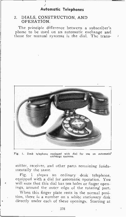
Automatic Telephones
2. DIALS, CONSTRUCTION, ANDOPERATION.
The principle difference between a subscriber'sphone to be used on an automatic exchange andthose for manual systems is the dial. The trans -
Fig. t. Desk telephone equipped with dial for use on automaticexchange systems.
mitter, receiver, and other parts remaining funda-mentally the same.
Fig. 1 shqws an ordinary desk telephone,equipped with a dial for automatic operation. Youwill note that this dial has ten holes or finger open-ings, around the outer edge of the rotating part.
When this finger plate rests in the normal posi-tion, there is a number on a white stationary diskdirectly under each of these openings. Starting at
378
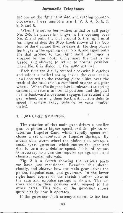
Automatic Telephones
the one on the right hand side, and reading counter-clockwise, these numbers are 1, 2, 3, 4, 5, 6, 7,8, 9 and 0.
When the subscriber wishes to dial or call partyNo. 246, he places his finger in the opening overNo. 2, and pulls the dial around to the right untilhis finger strikes the Stop Hook shown at the bot-tom of the dial, and then releases it. He then placeshis finger in the opening over No. 4, and again pullsthe dial around to the right until his finger isstopped by the hook. Once more the dial is re-leased, and allowed to return to normal position.Then No. 6 is dialed in the same manner.
Each time the dial is rotated clockwise it catchesand winds a helical spring inside the case, and apawl secured to the rotating plate slides over theteeth of the ratchet on a combined ratchet and gearwheel. When the finger plate is released the springcauses it to return to normal position, and the pawlin this backward movement engages the ratchet andgear wheel, turning them back with it at a definitespeed a certain exact distance for each numberdialed.
3. IMPULSE SPRINGS.
The rotation of 'this main gear drives a smallergear or pinion at higher speed, and this pinion ro-tates an Impulse Cam, which rapidly opens andcloses a set of contacts or Impulse Springs. Bymeans of a worm wheel the pinion also rotates asmall speed governor, which causes the gear anddial to turn at a definite speed. This, of course,is necessary to make the impulse springs open andclose at regular intervals.
Fig. 2 is a sketch showing the various partswe have just mentioned. Examine this sketchclosely, and observe how the main gear drives thepinion, impulse cam, and governor. In the lowerright hand corner of the sketch another view ofthe cam and impulse springs is shown. The ar-rows indicate their position with respect to theother parts. This view of the governor showsquite clearly how it operates.
If the governor shaft attempts to rc4t.,Le too fast
379
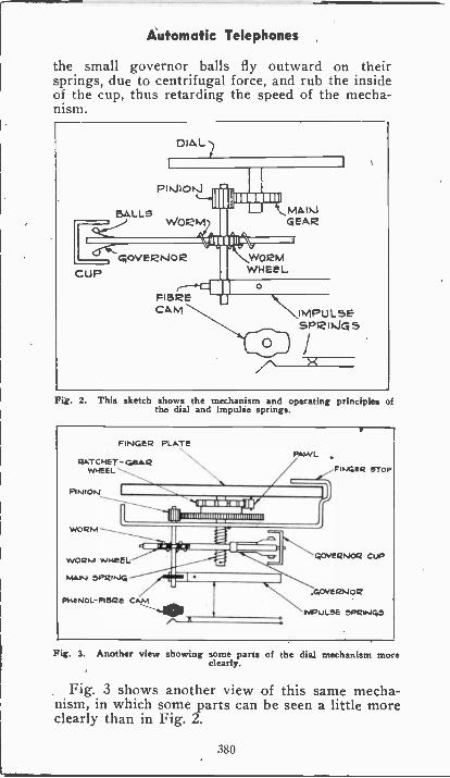
Automatic Telephones
the small governor balls fly outward on theirsprings, due to centrifugal force, and rub the insideof the cup, thus retarding the speed of the mecha-nism.
CuP
Fig. 2. This sketch shows the mechanism and operating principles ofthe dial and impulse springs.
FINGER PLATE
PUTCHET-GEARWHEEL
PINION
PAWL
11111.11=111.111=11111IIMIIMII
II imliii1111111111111111111111111111,,
enntirarir=MINIWORM
WORM WHEEL
SPRING
PHENOL-FIORE CAM
FINGER STop
C,OVEI2N04 CUP
.GOVERNOR
IMPULSE SPRINGS
Fig. 3. Another view showing some parts of the dial mechanism moreclearly.
Fig. 3 shows another view of this same mecha-nism, in which some parts can be seen a little moreclearly than in Fig. 2.
380
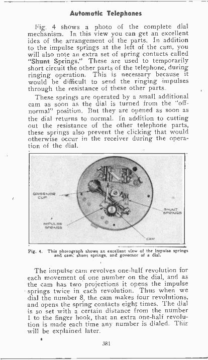
Automatic Telephones
Fig. 4 shows a photo of the complete dialmechanism. In this view you can get an excellentidea of the arrangement of the parts. In additionto the impulse springs at the left of the cam, youwill also note an extra set of spring contacts called"Shunt Springs." These are used to temporarilyshort circuit the other parts of the telephone, duringringing operation. This is necessary because itwould be difficult to send the ringing impulsesthrough the resistance of these other parts.
These springs are operated by a small additionalcam as soon as the dial is turned from the "off -normal" position. But they are opened as soon asthe dial returns to normal. In addition to cuttingout the resistance of the other telephone parts,these springs also prevent the clicking that wouldotherwise occur in the receiver during the opera-tion of the dial.
Fig. 4. This photograph shows an excellent view of the impulse springsand cam; shunt springs, and governor of a dial.
The impulse. cam revolves one-half revolution foreach movement of one number on the dial, and asthe cam has two projections it opens the impulsesprings twice in each revolution. Thus when wedial the number 8, the cam makes four revolutions,and opens the spring contacts eight times. The dialis so set with a certain distance from the number1 to the finger hook, that an extra one-half revolu-tion is made each time any, number is dialed. Tliirwill be explained later.
381
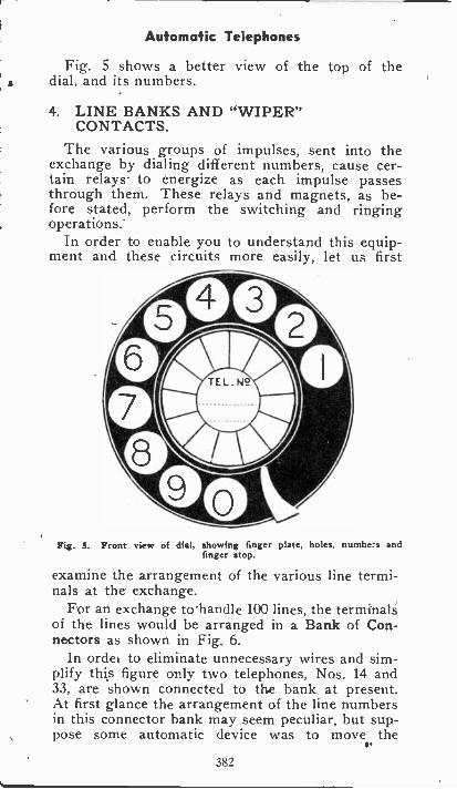
Automatic Telephones
Fig. 5 shows a better view of the top of thedial, and its numbers.
4. LINE BANKS AND "WIPER"CONTACTS.
The various groups of impulses, sent into theexchange by dialing different numbers, cause cer-tain relays- to energize as each impulse passesthrough them. These relays and magnets, as be-fore stated, perform the switching and ringingoperations.
In order to enable you to understand this equip-ment and these circuits more easily, let us first
Fig. 5. Front view of dial, showing finger plate, holes, numbers andfinger stop.
examine the arrangement of the various line termi-nals at the exchange.
For an exchange to'handle 100 lines, the terminalsof the lines would be arranged in a Bank of Con-nectors as shown in Fig. 6.
In order to eliminate unnecessary wires and sim-plify this figure only two telephones, Nos. 14 and33, are shown connected to the bank at present.At first glance the arrangement of the line numbersin this connector bank may seem peculiar, but sup-pose some automatic device was to move the
382
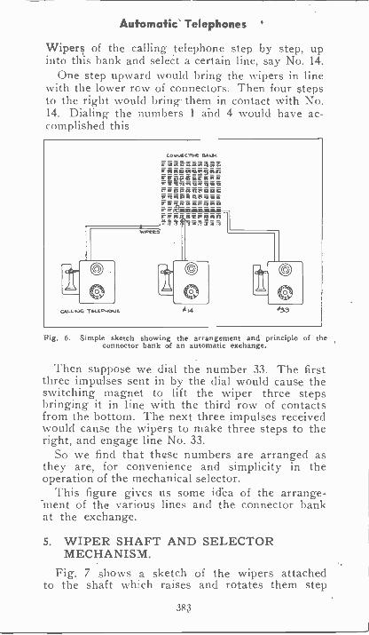
Automatic Telephones '
Wipers of the calling telephone step by step, upinto this bank and select a certain line, say No. 14.
One step upward would bring the wipers in linewith the lower row of connectors. Then four stepsto the right woukl bring them in contact with No.14. Dialing the numbers 1 and 4 would have ac-complished this
Fig. 6. Simple sketch showing the arrangement and principle of theconnector bank of an automatic exchange.
Then suppose we dial the number 33. The firstthree impulses sent in by the dial would cause theswitching magnet to lift the wiper three stepsbringing it in line with the third row of contactsfrom the bottom. The next three impulses receivedwould cause the wipers to make three steps to theright, and engage line No. 33.
So we find that these numbers are arranged asthey are, for convenience and simplicity in theoperation of the mechanical selector.
This figure gives us some idea of the arrange-ment of the various lines and the connector bankat the exchange.
5. WIPER SHAFT AND SELECTORMECHANISM.
Fig. 7 shows a sketch of the wipers attachedto the shaft which raises and rotates them step
383
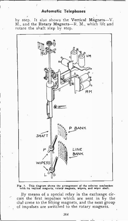
Automatic Telephones
by step. It also shows the Vertical Magnets-V.M., and the Rotary Magnets-R. M., which lift androtate the shaft step by step.
Vg. 7. This diagram shows the arrangement of the selector mechanismwith its vertical magnets, rotary magnets, wipers, and wiper shaft.
By means of a special relay in the exchange cir-cuit the first impulses which are sent in by thedial come to the lifting magnets, and the next groupof impulses are switched to the rotary magnets.
384
Automatic Telephones
Fig. 9 shows photos of both sides of one ofthese selector units.
Figs. 7 and 9 should be referred to while tracingout the circuit diagram in Fig. 8.
At the top of each unit in Fig. 9 are the relayswhich perform different switching operations in theexchange circuit. Underneath these are the verticalmagnets or lifting magnets, and below are therotary magnets.
On the shaft are two sets of notches called theVertical Rack and Rotary Rack respectively. Theseare engaged by the hooks which are operated bythe lifting and rotary magnets.
After the selector has completed a connection toa certain line, and the conversation is finished, then,when the subscriber hangs up his receiver, it closesa circuit to the Release Magnet, which trips thelocking mechanism, allowing the wipers and shaftto return to normal position by the action of aspring and gravity.
6. SIMPLIFIED CIRCUIT OF IMPORTANTPARTS.
In Fig. 8 is shown quite a complete diagramof the more important circuits of the automaticexchange.
It is not at all necessary for every student totrace and understand this diagram at present, butit provides excellent circuit tracing practice, andif you are sufficiehtly interested in the principlesof automatic telephones, or should later decide toprepare to specialize in this field, this simplifiedcircuit should be of great help to you in obtainingan understanding of the most important parts.
In order to trace a circuit of this kind, it isnecessary to do it step by step, and very carefully.If this method is followed, it will be found veryinteresting and not' nearly as difficult as it firstappears.
This diagram shows a complete connection be-tween a calling telephone, the automatic exchange,and the called telephone: Each circuit is traced
385
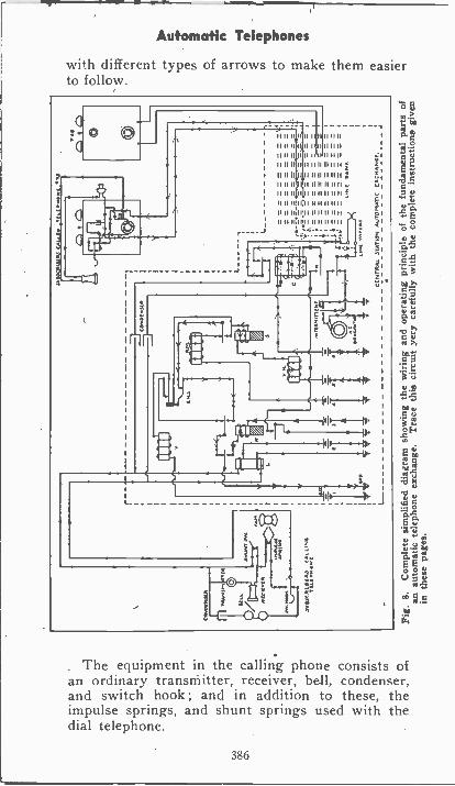
Automatic Telephones
with different types of arrows to make them easierto follow.
II 11 II II 11 11 11 II 11 11
11 li 11011 II 0 II II 11
II 11 II I 11 0 1.11 II 11
11 11 11 II 11 11n 111111 f
111111 n n 11 I11111 g
II.. 11 I1 11 11 11 11 11
11 II II II 11 11 11 11 11 11
II II 11.00 11 11 11 11 11
II 11 11 11 11 II II 0001111 11 11 II 11 11 11 11 II
Ezi
/ILX111----11,-
occ).114.
1
0I
1I1"--11. I
- -1
"cf p
2
411
o s
41iO 7.!
:v>
v11
te
Eg
e0
-41
C
ca.4E e'
gVyY
g .5
a.
The equipment in the calling phone consists ofan ordinary transmitter, receiver, bell, condenser,and switch hook ; and in addition to these, theimpulse springs, and shunt springs used with thedial telephone.
386
Automatic Telephones
As soon as the receiver is lifted from the hook,the hook switch will close the circuit, shown bythe small solid arrows, from the positive terminalof battery NO. Z through the top winding of relay"L." Then through the shunt switch, impulsesprings, and top contact of the hook switch atcaller's 'phone, back through the lower winding ofrelay "L," and to ground.
You will note that the ground connections inthis circuit are returned to negative of the bat-teries, so when starting to trace a circuit from anybattery, as soon as this circuit is completed backto ground, you will know it has returned to nega-tive of the battery.
To simplify this circuit a number of separatebatteries are shown.
These current impulses in the circuit we havejust traced, will cause relay "L" to become ener-gized and attract its armature. When this arma-ture is pulled down it closes a circuit shown bythe large solid arrows from the positive of batteryNo. 3. through the coil of relay "R," "make" contactof relay "L", and to ground, which completes thiscircuit.
The term "make contact" is used here, meaningthe contacts made when the relay is energized andthe armature attracted. The term "break contact"when used, means the contacts that are closed whenthe relay is de -energized. In other words, the con-tacts made when the armature is attracted arereferred td as "make contacts". Those made whenthe armature is released are called "break contacts".
When the circuit just traced through relay "R"is completed this relay becomes energized and at-tracts its armature. So we find that both relays"L" and "R" became energized merely by the sub-scriber removing his receiver from the hook.
Now, assume that he dials the figure 1. Whenthe dial is released, and as it returns to normal,the cam is rotated one-half turn, and opens theimpulse spring once. This momentarily opens thecircuit of the line relay "L", which is de -energized
387
Automatic Telephones
for an instant, and its contacts open the circuit ofrelease relay "R".
However, relay "R" remains energized throughthis short period even though its circuit was mo-mentarily opened. This is because it is a SlowActing relay, and does not release its armature theinstant the current is interrupted, but holds it forabout a second afterward. This will be explainedlater.
If the calling subscriber now dials the number 7,opening the impulse springs seven time's, the cir-cuit of relay `:L" will be broken each time, andallow its armature to release momentarily seventimes. Each time it releases, the circuit of relay"R" is broken for an instant, but relay "R" acts tooslowly to de -energize and release its armature dur-ing these periods, so it remains closed throughoutthe seven short interruptions of its circuit. Butsomething else did happen.
Keeping in mind that the armature of relay "R"is now attracted to the "make contact", we findthat the first time the armature of relay "L" wasreleased it closed a circuit shown by the small openarrows from the positive of battery No. 5 throughthe Vertical magnet, V.M., through relay "S","break contact" of O.N.S., "make contact" of relay"R", "break contact" of relay "L", and to ground.
The letters "O.N.S." stand for Off NormalSwitch, which will be explained later.
This circuit we have just traced energizes boththe vertical magnet and relay "S". Relay "S", be-ing another slow acting relay, will retain its arma-ture in an attracted position during current inter-ruptions of a fraction of a second.
The second time the armature of relay "L" wasreleased it allowed current to flow, as shown bythe large open arrows, from positive of battery No.5 through vertical magnet and relay "S" again, thenthrough the "make contact" of relay "S," "makecontact" of the off normal switch, "make contact"of Relay "R", "break contact" of relay "L," andto ground.
388
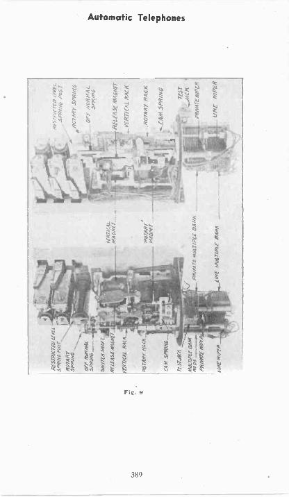
RE
5TH
IC r
tiiIi
POST
,
807/
417
SPR
ING
OFF
MrO
RM
AL.
SPR
ING
50Y
ITC
H-5
,1A
r
RE
LE
ASE
*16
.11
rt-R
7/(A
L R
AC
A
RO
TA
RY
RA
CA
M 5
PRI
rf 3
TJA
M
MZ
IL7/
Ptf
RO
DS
PRIV
AT
E P
r1Pr
-
tiNE
MU
LT
IPL
E
Hti.
45
VPH
17(4
4R
AC
K
rPA
CK
CA
M S
PRiN
G
iir4E
rr/P
tg
Automatic Telephones
The off normal switch is operated by the linewiper shaft as soon as it moves from off normalposition. So as soon as the dialing operation isstarted, the first movement of this shaft closes cer-tain contacts and circuits, but when the shaft isdropped and allowed to fall back to normal, it againopens these circuits.
Shortly after the last impulse of current haspassed through the relay "S" it will de -energize andcannot again become energized, because the circuithas been opened at the off normal springs. Each of'the seven impulses passing through the verticalmagnet causes it to raise the wiper shaft one step,so the line wiper will now rest in line with the sev-enth row of line bank contacts.
Now we are ready for the subscriber to dial thesecond number. Let's assume that he dials No. 5.This again rapidly opens the line circuit five times,causing the line relay "L" to release momentarilythe same number of times. Each time relay "L"is de -energized, now since the off normal switch isopened, a circuit can be traced as shown by thesmall dotted arrows from the positive of batteryNo. 4, through the rotary magnet R. M., breaksprings of relay "S," "make contact" of off normalsprings, "make contact" of relay "R," "break con-tact" of relay "L," and to ground.
These impulses in this circuit will cause the ro-tary magnet to become energized each time androtate the wiper shaft, carrying the wipers five stepsto the right. This brings them in contact with No.75 of the line bank, as indicated in the diagram.
The dotted lines from the normal position of theline wipers show the upward movement of the shaftcaused by the vertical magnet, and the rotatingmovement to the right caused by the rotary mag-net ; and they show the circuit which will now becompleted to the called subscriber's telephone.
As soon as the line wipers are in contact withNo. 75 in the bank a circuit is completed throughthe bell of the called telephone. This circuit canbe traced (backwards) by the large dotted arrowsfrom the top brush of the generator, through Inter -
390
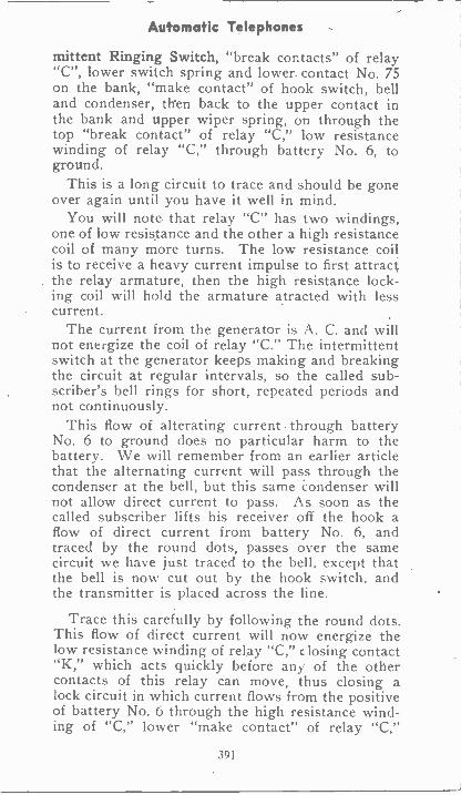
Automatic Telephones
mittent Ringing Switch, "break contacts" of relay"C", lower switch spring and lower, contact No. 75on the bank, "make contact" of hook switch, belland condenser, then back to the upper contact inthe bank and upper wiper spring, on through thetop "break contact" of relay "C," low resistancewinding of relay "C," through battery No. 6, toground.
This is a long circuit to trace and should be goneover again until you have it well in mind.
You will note that relay "C" has two windings,one of low resistance and the other a high resistancecoil of many more turns. The low resistance coilis to receive a heavy current impulse to first attractthe relay armature, then the high resistance lock-ing coil will hold the armature atracted with lesscurrent.
The current from the generator is A. C. and willnot energize the coil of relay "C." The intermittentswitch at the generator keeps making and breakingthe circuit at regular intervals, so the called sub-
rings for short, repeated periods andnot continuously.
This flow of alterating current. through batteryNo. 6 to ground does no particular harm to thebattery. We will remember from an earlier articlethat the alternating current will pass through thecondenser at the bell, but this same Condenser willnot allow direct current to pass. As soon as thecalled subscriber lifts his receiver off the hook aflow of direct current from battery No. 6, andtraced by the round dots, passes over the samecircuit we have just traced to the bell, except thatthe bell is now cut out by the hook switch, andthe transmitter is placed across the line.
Trace this carefully by following the round dots.This flow of direct current will now energize thelow resistance winding of relay "C," c losing contact"K," which acts quickly before any of the othercontacts of this relay can move, thus closing alock circuit in which current flows from the positiveof battery No. 6 through the high resistance wind-ing of "C," lower "make contact" of relay "C,"
391
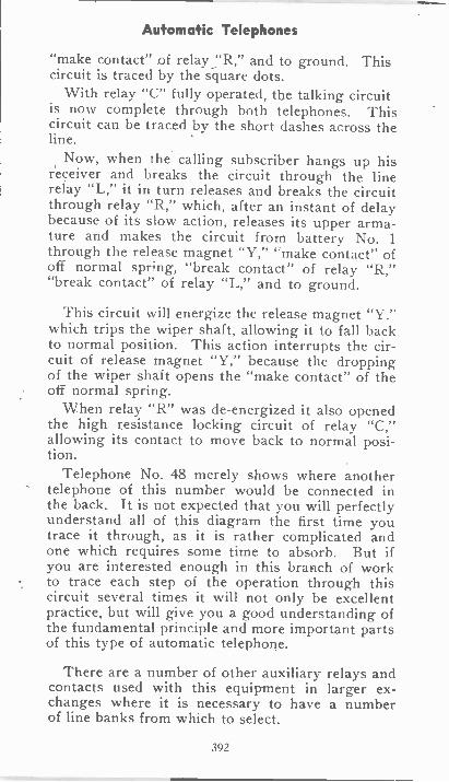
Automatic Telephones
"make contact" of relay "R," and to ground. Thiscircuit is traced by the square dots.
With relay "C" fully operated, the talking circuitis now complete through both telephones. Thiscircuit can be traced by the short dashes across theline.
Now, when the calling subscriber hangs up hisreceiver and breaks the circuit through the linerelay "L," it in turn releases and breaks the circuitthrough relay "R," which, after an instant of delaybecause of its slow action, releases its upper arma-ture and makes the circuit from battery No. 1
through the release magnet "Y," 'make contact" ofoff normal spring, "break contact" of relay "R,""break contact" of relay "L," and to ground.
This circuit will energize the release magnet "Y,"which trips the wiper shaft, allowing it to fall backto normal position. This action interrupts the cir-cuit of release magnet "Y," because the droppingof the wiper shaft opens the "make contact" of theoff normal spring.
When relay "R" was de -energized it also openedthe high resistance locking circuit of relay "C,"allowing its contact to move back to normal posi-tion.
Telephone No. 48 merely shows where anothertelephone of this number would be connected inthe back. It is not expected that you will perfectlyunderstand all of this diagram the first time youtrace it through, as it is rather complicated andone which requires some time to absorb. But ifyou are interested enough in this branch of workto trace each step of the operation through thiscircuit several times it will not only be excellentpractice, but will give you a good understanding ofthe fundamental principle and more important partsof this type of automatic telephone.
There are a number of other auxiliary relays andcontacts used with this equipment in larger ex-changes where it is necessary to have a numberof line banks from which to select.
392
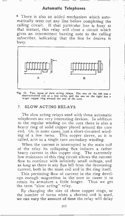
Automatic Telephones
There is also an added mechanism which auto-matically tests out any line before completing thecalling circuit. If that particular line is busy atthat instant, this relay will close a circuit whichgives an intermittent buzzing note to the callingsubscriber, indicating that the line he desires isbusy.
Fig. 10. Two types of slow acting relays. The one on the left has ashort-circuited coil of a few turns, and the one on the right has ala:ger copper ring around the end of the core.
7. SLOW ACTING RELAYS
The slow acting relays used with these automatictelephones are very interesting devices. In additionto the regular winding on the core there is also aheavy ring of solid copper placed around the coreend. Or, in some cases, just a short-circuited wind-ing of a few turns. This copper sleeve, as it iscalled, acts as a single turn secondary winding.
When the current is interrupted in the main coilof the relay its collapsing flux induces a ratherheavy current in this copper ring. The extremelylow resistance of this ring circuit allows the currentflow to continue with infinitely small voltage, andas long as there is any flux left from the decreasingcurrent, both in the main coil and in the ring itself.
This persisting flow of current in the ring devel-ops enough magnetism in the core to cause it toretain its armature a little longer. Thus we getthe term "slow acting" relay.
By changing the size of these copper rings, orthe number of turns when a shorted coil is used,we can vary the amount of time the relay will delay
393
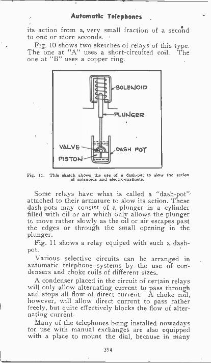
Automatic Telephones
its action from a. very small fraction of a secondto one or more seconds.
Fig. 10 shows two sketches of relays of this type.The one at "A" uses a short-circuited coil. Theone at "B" uses a copper ring.
Fig. 11. This sketch shows the use of a dash -pot to slow the actionof solenoids
Some relays have what is called a "dash -pot"attached to their armature to slow its action. Thesedash -pots may consist of a plunger in a cylinderfilled with oil or air which only allows the plungerto move rather slowly as the oil or air escapes pastthe edges or through the small opening in theplunger.
Fig. 11 shows a relay equiped with such a dash -pot.
Various selective circuits can be arranged inautomatic telephone systems by the use of con-densers and choke coils of different sizes.
A condenser placed in the circuit of certain relayswill only allow alternating current to pass throughand stops all flow of direct current. A choke coil,however, will allow direct current to pass ratherfreely, but quite effectively blocks the flow of alter-nating current.
Many of the telephones being installed nowadaysfor use with manual exchanges are also equippedwith a place to mount the dial, because in many
394
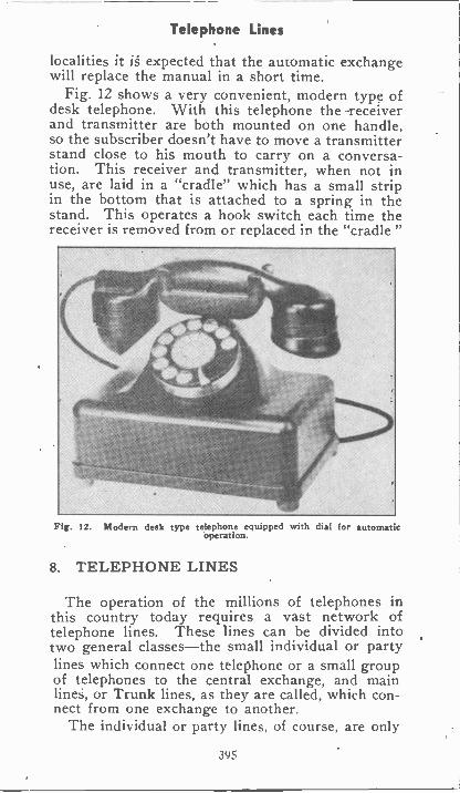
Telephone Lines
localities it is expected that the automatic exchangewill replace the manual in a short time.
Fig. 12 shows a very convenient, modern type ofdesk telephone. With this telephone the -receiverand transmitter are both mounted on one handle,so the subscriber doesn't have to move a transmitterstand close to his mouth to carry on a conversa-tion. This receiver and transmitter, when not inuse, are laid in a "cradle" which has a small stripin the bottom that is attached to a spring in thestand. This operates a hook switch each time thereceiver is removed from or replaced in the "cradle "
Fig. 12. Modern desk type telephone equipped with dial for automaticoperation.
8. TELEPHONE LINES
The operation of the millions of telephones inthis country today requires a vast network oftelephone lines. These lines can be divided intotwo general classes-the small individual or partylines which connect one telephone or a small groupof telephones to the central exchange, and mainlines, or Trunk lines, as they are called, which con-nect from one exchange to another.
The individual or party lines, of course, are only
395
Telephone Lines
in use when the subscribers whose telephones areon them are talking.
The trunk lines, however, carry the main businessbetween exchanges and large towns, and are keptbusy the greater portion of the time. These trunklines might be called the arteries of the telephonesystem and are fed by the smaller branch lines fromeach exchange.
9. GROUND CIRCUITS. CABLES
Some telephone lines are made up of two insu-lated wires for each circuit and known as metalliccircuits. Other lines use one insulated wire on thepoles and the other side of the circuit is completedthrough earth by carefully made ground connec-tions. Some lines which use a two -wire or metallictalking circuit use a ground circuit for ringing.
Telephone line wires are usually bare and with-out any insulation except the small glass insulatorswhich support them on the poles. Under normalconditions this is sufficient insulation because theydo not operate a high voltage. Many telephonelines use galvanized steel wire and some use copperwires. Most all of us have seen trunk lines following highways or railroads from one town to anotherand with their dozens of wires on numerous crossarms on the poles. This type of line is being re-placed in many localities by the more compact tele-phone cables.
The large masses of open wires on the older linesoffer a great deal of wind resistance and accumulateenormous loads of sleet at certain times of the year.This has a tendency to break down poles and dis-able the lines, making them very costly to keep inrepair. Where cables are used, one lead sheathabout 2 to 3 inches in diameter may carry from 500to 1,200 pairs of small wires. These individualwires are all insulated from each other with properwrappings and the entire cable insulated from thelead with an additional wrapping. Such cables arevery heavy and not strong enough to support theirown weight between long spans. Therefore, theyare usually supported by what is called a "Mes-senger" cable made of stranded steel wires, and to
396
Transposition
which the lead cable is attached at frequent inter-vals by means of hooks or wire supports.
The lead sheath protects the wires from moistureand injury, and cables of this type can be run un-derground in cities, as well as overhead on polesacross the country. In connecting or repairing suchcables the small wires are spliced separately, sol-dered, and carefully reinsulated with sleeves ofpaper or other insulation over the splice. Thenumerous splices are often staggered or made afew inches apart to prevent too large a bulge in thecable at the joints.
When the wires are all spliced; a large leadsleeve, which has been previously slipped over thecable, is then slid over the splice and sealed in placewith hot lead, similar to a "wiped" joint in leadpiping.
The entire splice is then dried out by pouringhot parafin through it and finally filled with parafinor other insulating compound, and the small fillerhole in the lead sleeve is then sealed tightly
All moisture must be kept from the inside of suchcables and splices.
10. LIGHTNING PROTECTION ANDTRANSPOSITION
Where open wire lines are used, it is customaryto run lightning ground wires from the top of cer-tain poles along the line down to an earth groundat the bottom of the pole. These wires serve assmall lightning rods to drain severe static chargesand lightning from the telephone line. Small light-ning arresters are often used at the 'phones on ruralparty lines to ground any lightning charges andprevent damage to telephones and property.
Where telephone lines run parallel to power linesthey often pick up, by magnetic induction, an inter-fering hum. To avoid this, the pairs of wires shouldoccasionally be crossed into opposite positions onthe poles or cross arms, so that one wire will notbe closest to the transmission line throughout itsentire length.
397
Phantom Circuits
This crossing of wires to prevent induced inter-ference is known as transposition. Sometimes it isalso done to avoid "cross -talk" or induction fromother telephone wires.
Transposing the wires frequently and evenly willbalance out most of this induction. Telephone linesshould never be left close enough to high voltagepower lines so that there would be danger of themcoming in contact with each other, for in case theydid people using the telephone lines might be in-jured.
Satisfactory telephone operation depends to quitean extent on proper line construction. Therefore,all telephone lines should be made with the propermaterials and the wires properly spliced with lowresistance joints, ground connections kept in goodcondition, etc.
11. PHANTOM CIRCUITS
Considerable economy and saving of wire car, beeffected in telephone line construction by the useof what are known as "Phantom" circuits. By thismethod one additional circuit can be obtained foreach pair of lines already in existence. This canbe done without the addition of any other wires,merely by using two existing lines, one to formeach side of the new line or phantom circuit.
By the use of proper induction coils, or RepeaterCoils, as they are called, a conversation can becarried on over this phantom line without inter-fering with either of the two actual lines. A re-peater coil is simply a transformer with primaryand secondary windings of an equal number ofturns.
Fig. 15 shows the manner in which a phantomcircuit is obtained from two metallic circuits. LinesNo. 1 and 2 are ordinary metallic lines or physicalcircuits using repeater coils to transfer the currentimpulses from the transmitter circuits to the lines.Line No. 3 is a phantom circuit obtained by con-nection of its coil to the exact center of each of theothers on lines 1 and 2. With this connection thecurrent in line 3 can divide equally through each
398
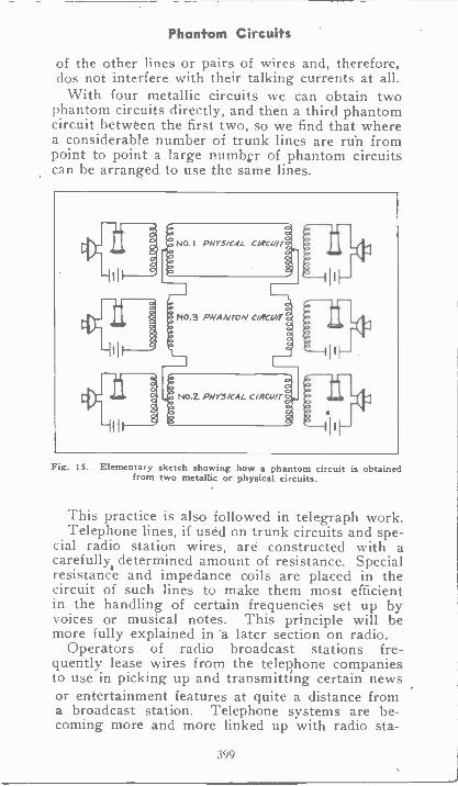
Phantom Circuits
of the other lines or pairs of wires and, therefore,dos not interfere with their talking currents at all.
With four metallic circuits we can obtain twophantom circuits directly, and then a third phantomcircuit between the first two, so we find that wherea considerable number of trunk lines are run frompoint to point a large number of phantom circuitscan be arranged to use the same lines.
it
NO. I PHYSICAL C/Re-Wr
NO.3 PHAA/TOAI cocor
NO.2. PHYSICAL ciRcuir
Fig. 15. Elementary sketch showing how a phantom circuit is obtainedfrom two metallic or physical circuits.
This practice is also followed in telegraph work.Telephone lines, if used on trunk circuits and spe-
cial radio station wires, are constructed with acarefully, determined amount of resistance. Specialresistance and impedance coils are placed in thecircuit of such lines to make them most efficientin the handling of certain frequencies set up byvoices or musical notes. This principle will bemore fully explained in 'a later section on radio.
Operators of radio broadcast stations fre-quently lease wires from the telephone companiesto use in picking up and transmitting certain newsor entertainment features at quite a distance froma broadcast station. Telephone systems are be-coming more and more linked up with radio sta-
399
Telephone Troubles
tions, not only for amusement programs, but forthe trans -oceanic and commercial conversations aswell.
12. TELEPHONE TROUBLES
Faults and troublqs arising in telephones or tele-phone exchanges can usually be located by the samegeneral methods of systematic testing that havebeen covered in connection with other signal cir-cuits. A diagram of the wiring and connections isalways of the greatest help in testing any telephonecircuit.
Some of the more common telephone troubleswhich occur in the separate parts, such as a trans-mitter, receiver, hook switch, etc., have already beenmentioned. Other likely places to look for faultsare at the spring contacts of key switches and re-lays, which may have become burned, dirty, or bentout of shape ; wire terminals, which may have be-come corroded or loose on the binding screws ; weakbatteries, weak magneto magnets, weak receivermagnets, etc.
Telephone circuits and equipment can often betested very conveniently with a telephone receiver,as well as with test lamps and buzzers. The re-ceiver can be used to determine if the talking cur-rent is coming through to certain circuits, and alsoto determine whether high resistance circuits arecompleted or not, by the clicks which should beheard in the receiver when its terminals are touchedto any line circuit.
Careful application of your knowledge of theprinciples of fundamental telephone parts and cir-cuits and methods of systematic trouble shootingshould enable you to locate most any of the ordi-nary troubles in telephone equipment.
400
Automatic Telephones
EXAMINATION QUESTIONS
1.-Give the name of one automatic Telephonesystem that has proven to be very successful.
2.-Is a central operator required to complete acall on an automatic system ?
3.-What operation does the impulse cam performon an automatic Telephone?
4.-For what are shunt springs used in the auto-matic Telephone ?
5.-What operation does the release Magnet per-form?
6.-What is the main difference between a "slowacting" relay and an ordinary relay?
7.-Do all telephones require two lines wires?
8.-For what purpose is the MESSENGER cableused ?
9.-How may telephone wires be arranged to pre-vent "cross -talk" or inductive interference?
10.-What advantage is there in using PhantomCircuits?
401
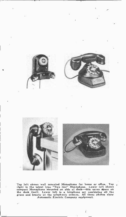
Top left shows wall mounted MOnophone for home or office. Topright is the latest type "Two line" Monophone. Lower left showscompact Monophone mounted on side of desk-this saves space onthe desk itself. Lower left is a telephone set combining all thegrace and beauty of the telephonic science. All these photos show
Automatic Electric Company equipment.
INDEXA
Alarm, plug in types, 291Automatic signal machines. 288balancing systems, 277-278fire equipment, 279-282heavy duty bells, 286"Howlers" signal horns, 287photo-Benjamin Electric, 290
H. Channon, 291-292signal recorders, 288"Vitalarm" type, 295
Annunciators '245-252locating faults of, 251principles of, 246terminal tests of. 248
Ammeter, photo. 20Ampere hour, definition, 20Automatic telephone. 381-401
BBalancing alarm systems, 277-278Bells, bias polarized, 342
door signal, types of, 816 'muffling of, 220signal, vibrating, single stroke
& combination, 211-217simple call, 188troubles of. 213
Belts, static in, 176Burglar alarms, 203Buzzers, signal, 219-221
CCurrent, electric, 16-20Cables, telephony, 896Call systems, 297-321Capacitance, 171-172Capacitors, 171Cells. 88-106
air -cell battery, 100current & voltage of, 89Daniell type. 91dry type of, 96Edison primary type. 93efficiency of a battery, 102electrolyte, 100gravity type, 92
Coils, magnetic fields around. 136Coils, primary & secondary, 88Cells, storage cells. 100
two fluid types of, 91voltage & current of. 89
Changes, chemical in battery, 22Charge, of electricity, 169Chemical, changes in battery, 22Chimes, electric signal types, 318Circuits. 276-295
complete electric (diagram), 16electrical, 13-16holding relay. 271-276open circuit holding, 272
Conductance, 84Conductors, resistance in, 33
types of. 6Connections, 62-68
combined series & parallel. 81-87examples, series & parallel,
84-86
Connections. Cont'd.lock switch (alarms), 27parallel. 52-61parallel (diagrams), 63-56polarity of, 80series, 38-39
DeDiagram, construction dry cell. 96Dielectric, constant, 172
EElectric chimps, produced by
friction, 174Electricity,
alarm circuits, 276-295annunciators, 245-252automatic telephones, 381-401call systems, 297-321capacitance, 171-172cells, 88-106chemical action of, 87circuits of, 13-16combined series & parallel
connections, 81-87conductance, 34conductors of. 6current of, 16-20efficiency of apparatus, 102-106electricity in motion, 109electrolysis, 106electromagnetic induction,
155-169electromagnetism, 131-155electromotive force, 21-24electroplating, 106energy, 68-79how it behaves, 1-8how to find a network, 62insulators of. 7lightning, 177-178lightning rods, 180-184magnetism, 115-181motion, 83parallel connections of, 53-56power, 68-79power line drop. 77-79quantities of, 18relation of voltage, current,
and resistance, 40-42relays, 223-243resistance, 24series connections, 37signal equipment, 211-244signals switches, 198-210
systems, 185-192. 308static electricity, 169-184symbols of, 85systems of, 9-12telephony, 323-401telephone circuits. 349-352
exchange, 363receivers, 334-336
what electricity will do. 8Electromotive force. 21-24Electrolysis,
electrolytic refining, 110water & salt, 109
Electrolytic furnace, 112Electromagnet. 138
calculations of, 147circuits of. 144construction of, 140polarity of, 141
Electroplating, 106Electrostatic fields, 178Energy, 3, 68-79
FFields. electrostatic, 173Friction, electric charges, 174
GGenerator. DC. photo, 2
photo, 10principles, A.C., 160principles, D.C., 162
HHeat, 4
IInduction coils. 163Insulators, types of, 8Induced electric pressure, 155
magnitude of, 159
LLamps, telephone switchboard,
360Laws, Ohms, 43-52Light, 4Lightning, 177-178
Rods, 180-184
MMagnetic, circuit,
circuit units of system, 144c.g.s. system. 149
Magnetic fields, around coils, 136action of. 121
Magnetic forces between wires,135
Magnetic,lines around conductor, 133lines of force. 119materials, 124properties of materials, 122
Magnetism,Earth's, 118consequent poles, 130shields. 129permeability, 126reluctance, 126artificial. 115attraction & repulsion, 117
Magnets,compound, 130compass test for polarity, 181effect of air gap. 128lifting power of, 148poles, 117natural, 115pulling strength of, 127
Magnets, Cont'd.testing coils for faults, 152winding & repair. 150
Meters. ammeter (photo), 20
NNetwork, how to find a, 62Non-magnetic materials, 124
0Ohms, law of, 43-52
applying law of, 48-52Openers, door, magnetic, 222
P.Parallel
connections, 52-61wires, magnetic forces between,
135Permeability, magnets, 126Phantom, circuit diagram, 399Polarity, 31Power, line drop, 77-79
line loss, 79field problems, 75-76formulas of, 71r72power & energy, 68-79
Pressure, difference in, 30-32Primary, cells, 88
Edison type cell, 93
QQuestions,
alarm circuits, 296relays. 244signal systems, 321signal systems, 270signal switches, 210telephony, 401telephony, 375telephony, 347
RRelays, 223-243
adjustment & care of, 241alarm circuits. 276-295burglar alarm. 236-237circuits of, 225-228Clapper type of, 225holding combination type, 275Dixie type of, 225double circuit holding type,
273-274drop or constant ringing type,
228ground circuits, 238open circuit holding type of,
272open, closed, double circuit
types of, 285-236Pony type of, 2243 section alarm. 274terminals & connections.
253-254telegraph systems, 238terminal tests, 240Western Union type of, 223
Receivers, telephony. 384Reference point, definition, 30
Reluctance, magnets, 126Relation, voltage, current &
resistance, 40-42Residual magnetism, 140Resistance, effect of length, 33Rods, lightning, 180-184
SSecondary, cells, 88Shields. magnetic, 129Signal,
call system without switches,258
closed circuit (burglar alarm),266
common devices, 191-192connecting vibrating types for
series 'operation, 261current supply trouble, 195desk block types. 202equipment, 211-244motor generator systems, 192office call systems. 265open circuit systems, 254push button switches, 202return call system, 256selective master call systems,
259-260selective call circuit, 255silent type, 220switches, 193-210systems, electric, 185-192trouble shooting, 308vibrating bell-constant
ringing, 268wiring (photo), 197
Solenoids, 137Sound, 5Symbols, 35
signal systems, 253use of signal systems. 189-190
System, auto electric (diagram),14
call, 297-821electricity, 9-12electric chimes types. 318emergency wires. 304estimating installation costs,
312-313"flush" type of equipment, 317layout, 299call-materials, 305materials (photo). 310modern door bell signal, 316running the wires, 299safety rules, 306
.testing for proper wires. 302tools & supplies (signal). 314trouble shooting (call). 308trouble tests. 303
Static, method of control, 174electricity, belts static, 176control & protection against,
174explosion from, 175
Switchboards,connections, 365telephone, manual type, 366
Switches,signal-floor type. 206multiple key (photo), 209key-telephone, 360
Switches. Cont'd.key & lock (signal), 206signal, 196-210thermal & heat (signal). 207troubles of, 208
TTelephony, 323-401
automatic, 381-401automatic type principles, 377
dials. 378exchange (diagram), 386relays, 393
batteries, 337hells, 339-343cables, 368-396central energy systems, 358circuits, 349-352current supply, 337desk type exchange, 369exchanges, 356-375exchange (diagram), 363ground circuits, 396hook switch, 335impulse spring, 379induction coil. 337
(photo), 338inter -communication system.
374(diagram), 353
jacks and drops, 362key switches, 360lines, 395line banks, 382magnetos, 344
(photo), 345manual switchboard, 366parts, 329automatic type. 385phantom circuits, 398plugs, 361polarized bell, 343principles of operation, 324receivers, 334relay (photo), 370rural line type diagram, 350
(photo), 349selector, mechanism, 383switchboards (manual opera-
tion). 357connections. 365lamps, 360
transmitters, 330-333terminals, 368transmitting & reproducing
sound waves, 326transposition, 397troubles of, 401wiper contacts of. 382
Terminal, voltage at, 26Transformer, action of. 166
action under load, 166bell, 193-196construction of. 166purpose and use of, 165ratio. 166
Transmitter, telephony, 330-333Traps, burglar alarm, 206
VVoltage, 26-29
drop in. 27terminal. 26

,
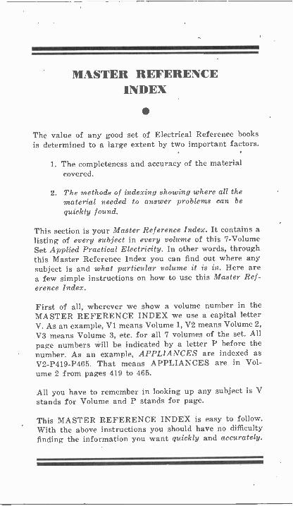
MASTER REFERENCEINDEX
The value of any good set of Electrical Reference booksis determined to a large extent by two important factors.
1. The completeness and accuracy of the materialcovered.
2. The methods of indexing showing where all thematerial needed to answer problems can bequickly found.
This section is your Master Reference Index. It contains alisting of every subject in every volume of this 7 -VolumeSet Applied Practical Electricity. In other words, throughthis Master Reference Index you can find out where anysubject is and what particular volume it is in. Here area few simple instructions on how to use this Master Ref-erence Index.
First of all, wherever we show a volume number in theMASTER REFERENCE INDEX we use a capital letterV. As an example, VI. means Volume 1, V2 means Volume 2,V3 means Volume 3, etc. for all 7 volumes of the set. Allpage numbers will be indicated by a letter P before thenumber. As an example, APPLIANCES are indexed asV2 -P419 -P465. That means APPLIANCES are in Vol-ume 2 from pages 419 to 465.
All you have to remember in looking up any subject is Vstands for Volume and P stands for page.
This MASTER REFERENCE INDEX is easy to follow.With the above instructions you should have no difficultyfinding the information you want quickly and accurately.
MASTER REFERENCE INDEX
INDEXA
Absorption refrigerators, typesof, V6 -P101
A. C. meters, V5 -P181 -P205voltmeters, ammeters, V,5 -P182motors, V4 -P257 -P343
Action, battery charge, V7 -P227discharge, V7 -P228
Aids, starting, Diesel, V7 -P421Air cells, Diesel, V7 -P393
compressor, V7 -P422Air conditioning, V6
combination, furnace andcooling, V6 -P225
commercial types (photo)V6 -P298
ceiling type, V6 -P253cooling the air, V6 -P259cutaway photo, home
installation, V6 -P256dehumidifying the air, V6 -P264filters of, V6 -P272filtering the air, V6 -P274grilles, V6 -P291heat leakage, factors in
material, V6 -P289heat load calculations,
V6 -P287humistat, V6 -P271'humidifying, V6 -P268heating the air, V6 -P257installation & testing, V6 -P301insulation of buildings,
V6 -P295principles of, V6 -P249 -P255plenum chamber, V6 -P254photo system for store.
V6 -P251 -P252photo, York Ice Machine
Co., V6 -P10photo, office installation,
V6 -P261photo of train, V6 -P262restaurant cooling
problems, V6 -P299room cooler-Westing-
house, V6 -P260room coolers, V6 -P7 -P258types of, V6 -P254
unit. Westinghouse, V6 -P7Alarm, plug-in types, V1 -P291
automatic signalmachines, VI -P288
balancing systems,V1 -P277 -P278
fire equipment, VI -P279 -P282heavy duty bells, V1 -P286"Howlers" signal
horns, V1 -P287photo-Benjamin Elec-
tric, VI -P290H. Channon, Vl-P291-P292
signal recorders, VI -P283"Vitalarm" type, Vl-P295
Alternating current, V4average value, V4 -P11
circuits of, V4 -P22 -P26capacity. V4 -P36effective & maximum
values, V4 -P13effect of lagging, V4 -P20flow of, V4 -P13 -P14generation of, V4 -P9 -P11history of, V4 -P1 -P6nature of, V4 -P8phase relation, V4 -P19relays, V4 -P643 -P647reassembly of motors, V4 -P683sine curves, V4 -P11
Alternation, V4 -P11Alternators
adjusting loads, 'V4 -P125operation of, V4 -P130 -P132
and paralleling,V4 -P113 -P133
revolving field,V4 -P87, V5 -P87
shutting down, V4 -P126starting up, V4 -P124turbine types, V4 -P93vertical and horizontal
types, V4 -P90 --P92Ammeters, V3 -P156 -P160
connections for, V3 -P158(photo) V1 -P20principles of, V3 -P147
Ammonia, V6 -P92systems, V6 -P241
Ampere -hour, def., VI -P20Amplification, V6 -P333Amplifiers, V6 -P362 -P372
class B operation, V6 -P363Annunciators, V1 -P245 -P252
locating faults of, V1 -P251principles of, V1 -P246terminal tests of, V1 -P248
Antennas, radio, V6 -P309Appliances, V2 -P419 -P465
normal maximum watts takenby appliancemotors, V2 -P465
testing equipment, V2 -P463troubles, V2 -P462lubrication, V2 -P461motors, split phase-capacitor
universal serieswound, V2 -P445 -P451
synchronous motor, V2 -P454thermostat differentials,
V2 -P422thermostat for starting,
V2 -P419Armature, alternator
types, V4 -P94baking of, V5 -P157
coils for, V5 -P20number of turns and size
of wire, V5 -P20slots, V5 -P6
slip ring, troubles, V7 -P120Armature winding, V5
flux, V5 -P16banding of armatures, V5 -P65
MASTER REFERENCE INDEX
commutators, V5 -P8action of, V6 -P13
coils for, V5 -P20 -P30span, V5 -P38connecting of coils, V5 -P42
changing old motor for newconditions, V5 -P57
collecting data from oldwindings, V5 -P63
cutting out faultycoils, V5 -P78
cycles & alternators, V5 -P85connections of starting
windings, V5 -P102centrifugal switches, V5 -P104connecting 3 phase
winding, V5 -P124changing operating
voltage, V5 -P139changes in number of
phases, V5 -P145changes in frequency, V5 -P147changing number of poles
speed, V5 -P149determining commutator
pitch. V5 -P47element windings for large
armatures, V5 -P56experiments, V5 -P80effect on current when chang-
ing voltage, V5 -P141field poles, V5 -P3frequency of AC
circuit. V5 -P86fractional pitch
winding, V5 -P135generators & motors, V5 -P3governor effect EMF, V5 -P19growler operation
& use, V5 -P68growler indications on wave
windings, V5 -P69inserting coils for lap
windings, V5 -P40lap wave windings,
V5 -P33 -P50loose coil leads, V5 -P73lap windings. V5 -P112motor principles, V5 -P17multiplex windings, V5 -P59marking & connecting
coil leads. V5 -P121marking stub connections,
V5 -P125number of turns & size of
wire, V5 -P20neutral plane, V5 -P61110 volt winding. V5 -r53open circuit. V5 -P78operating principles of 3 phase
motofs. V5 -P110operating voltage
& changes. V5 -P142preparing the armature for
winding, V5 -P88procedure, V5 -P52procedure of winding 3 phase
stator, V5 -P119poles & phase connections,
V5 -P125
reversed coil. V5 -P74revolving field alternators,
V5 -P37rotors, V5 -P96
windings for rotors, V5 -P137running & starting winding
for single phasemotors, V5 -P100
reversed coil groups, V5 -P169small 2 element
winding, V5 -P54symmetrical connections,
V5 -P62short circuits, V.5 -P72shorts between coils, V5 -P75single phase currents, V5 -P89skein windings, V5 -P98stators, V5 -P97special connections for con-
venient voltagechanges, V5 -P144
taping & shaping coils, V5 -P313 volt windings, V5 -P5432 volt winding, V5 -P54testing, V5 -P672 phase currents, V5 -P913 phase currents. V5 -P93terms & definitions, V5 -P111types of coils for stator
winding, V5 -P117testing for correct
polarity, V5 -P140use of insulating varnish &
compounds onwindings, V5 -P155
winding data chart, V5 -P23winding coils, V5 -P29wave windings, V5 -P43 -P50winding small armatures,
V5 -P51Arrangement, valves, V7 -P16Assembly, battery plate
groups, V7 -P292Audio frequency amplifiers,
V6 -P348Automatic starter controls,
V7 -P136 -P137telephone, VI -P381 -P401spark advance, V7 -P64
Automotive, modern motor carequipment, V7 -P1
Auxiliary controls, generator,V7 -P159
Aviation lighting, V2 -P326 -P343airplane lights. V2 -P339beacons. V2 -P326boundary lights, V2 -P332hangar & shop, V2 -P336illuminated wind direction
indicators. V2 -P334landing field lights, V2 -P327
BBaffles, water drain, V6 -P221Baking, armature, V5 -P157 -P160Balancing alarm systems,
V1 -P277 -P278Band, wave, V6 -P356Banding, armature, V5 -P65
MASTER REFERENCE INDEX
Barostat, two temperature valve(diagram) V6 -P230
valve, on flooded system.V6 -P233
on flooded and dry system,V6 -P233
on dry system, V6 -P233Battery, V7
assembly of plates groups,V7 -P292
burning a connection, V7 -P288charge & discharge action,
V7 -P306charging Nickle Iron cells,
V7-15308Cadmium test, V7 -P285charging with DC rheostat,
V7 -P264charging bench, V7 -P261charging-motor geqerator
constant potentialmethod, V7 -P260
charging in series, V7 -P258charging rates, V7 -P255charging of, V7 -P253cycling of, V7 -P249capacity of, V7 -P243 -P245charging NEW batteries.
V7 -P298chemical action-charge,
V7 -P227chemical action-discharge,
V7 -P228cells, V7 -P201construction of, V7 -P209capes, V7 -P215cell containers of, V7 -P215Electron Bulb charging,
V7 -P255 -P257Edison storage cells, V7 -P302electrolyte, V7 -P217defective platps-replacing,
V7 -P282by -rate discharge test,
V7 -P240hydrometers, V7 -P220internal resistance of,
V7 -P309lead burning, V7 -P284
adjustment torch, V7 -P286isolators, V7 -P214meters for testing,
V7 -P236 -P23,8NiCkle Iron cells, advantage
of, V7 -P305(photo), V7 -P307care of, V7 -P310
on -the -line voltage test,V7 -P232
open circuit voltage test,V7 -.P233
operation of constantpot, V7 -P262
plates, V7 -P201buckled, V7 -P269
preparation for storage.V7 -P295
questions, V7 -P251questions, V7 -P277questions, V7 -P314
questions, V7 -P226retainers of, V7 -P214reassembly of, V7 -P283repair of, V7 -P279storage, V7 -P201 -P315service of, V7 -P273 -P275shop equipment, V7 -P299separators, V7 -P211specific gravity of. V7 -P218storage (photos), V7 -P35 -P36testing of, V7 -P228terins-battery action V7 -P229troubles of, V7 -P266terminal posts, V7 -P293thermometers, V7 -P225voltage test, V7 -P231
Bearings, ball and roller, typesof, V4 -P676
lubrication of, V4 -P67.8breaking in new, V4 -P688compressor, V6 -P168Diesel, V7 -P491
wear and clearances,V7 -P505
dust seals, V4 -P686frozen, V4 -P692installation of, V4 -P681loss of oil, V4 -P689motor and generator, V3 -P23overheating of, V4 -P690sleeve types of. V4 -P679tight or worn, V5 -P171
Bells, bias polarized, V1 -P342door signal, types of, V1 -P816muffling of, V1 -P220signal, vibrating; single stroke
& combination, VI-P21I-P217
simple call, Vi -P188troubles of, V1 -P213
Belts, static in, V1 -P176Bench charging, V7 -P261Bendix drive mechanism,
V7 -P130Bends, conduit, V2 -P76 -P78Bias, grid, V6 -P328Block, cylinder, V7 -P6Blowers, V6 -P281
charging, V7 -P336Boiling point, V6 -P19Boxes, outlet, V2 -P57 -P60Braking, dynamic, V3 -P294 -P801
regenerative, V3 -P301Breakers, automotive, V7
construction diagram, V7 -P72distributor mechanism,
V7 -P58magnetic protective, V7 -P187setting of, V7 -P73
Breakers, circuit, 'V3-PI26care and maintenance,
V3 -P132instrument switches, V3 -P184operation, V3 -P127shunt trip coils, V3 -P131trip coil overload release,
V3 -P129Brushes, automotive, V7
Bendix, V7 -P129
MASTER REFERENCE INDEX
third brush regulation.V7 -P151
Brushes, motor and generator, VScarbon, V3 -P103-16, P307-20experiments. V3 -P115holders, V3 -P19requirements. V3 -P308 -P103fitting new to old commu-
tators, V3 -P113cement for attaching leads.
V3 -P111leads & shunts, V3 -P314 -P109pressure & tension, V3 -P108use of graphite in. V8-P107special types of, V3 -P107resistance, V3 -P105photos of, V3 -P104materials for, V3 -P309-P108
Buckling, battery plates, V7 -P269Bulb, charging, electron,
V7 -P255 -P257Burglar alarms, V1 -P203Burning, lead, V7 -P284Bus bars, V3 -P135 -P136
connections of, V3 -P137Buzzers. signal, V1 -P219 -P221'BX, cutting and stripping,
V2 -P100BXL, use of, V2 -P101
CCabinet, refrigeration,V6 -P78
G.E. (photo), V6 -P218repairs, V6 -P216
Cable, armored, V2 -P97advantages of, V2 -P98
lugs, V2 -P37telephone, V1 -P396
Cadmium test, V7 -P235Call systems, V1 -P297 -P321Capacitance, V1-P17I-P172Capacitors, VI -P171Capacity, battery, V7 -P243 -P245
electric, V4 -P36summary of, V4 -P42units of, V4 -P42
Capillary tubes, V6 -P68Carbon brushes, V3 -P307 -P320
dioxide. V6 -P92Carburetor operating levers,
V7 -P14principles of, V7 -P11
Carrene. V6 -P94Carrier unit (photo),
V6 -P251 -P252Cases, battery. V7 -P215Cells, battery, V1 -P88 -P106
air cell, VI -P100current and voltage of,
VI -P89Daniell type, V1-P91dry type, V1 -P96Edison primary type,
VI -P93efficiency of, V1-P102electrolyte for, Vl-P100gravity type, Vl-P92two fluid types. VI -P91
storage. V1 -P100
lead -acid, V7 -P201lead plate (photo), V7 -P203nickel iron, V7 -P305
Center upper dead, V7 -P9lower dead, V7 -P9
Centrifuging, V7 -P406Chambers, combustion, V7 -P7Changes, chemical, battery,
VI -P22voltage, radio, V6 -P329
Charge, battery. V7 -P306adjusting the rate of, V7 -P153charging various methods,
V7 -P117with motor generator, V7 -P260in series, V7 -P258battery, V7 -P253new batteries, V7 -P298electric, V1 -P 1 69refrigeration, determining
amount of, V6 -P186Charging, refrigerant, V6
gaseous method, V6 -P200general procedure for, V6 -P200low side, V6 -P200high side float systems,
V6 -P200capillary tube systems,
V6 -P201low side float systems,
V6 -P201expansion valve systems,
V6 -P202liquid method, V6 -P202photo, valve, V6 -P171
Charts, refrigeration head pres-sure temperature,V6 -P178
trouble shooting, V3 -P347winding data, V5 -P23
baking temperature,V5 -P159
wire. V2 -P85 -P88Chemical changes, battery,
VI -P22dehydrator, V6 -P188
Chevrolet lamp load, lighting,V7 -P167
Chimes, electric signal, V1' -P318Chrysler engine (photo), V7 -P22Circuits, V1 -P276 -P295
branch, V2 -E159complete, VT -P15, V7 -P109electrical, V1-P13 -P16holding relay, VI -P271 -P275magnetic, four -pole, V3 -P30paralleling A.C. V4 -P49open circuit holding, V1 -P272primary (diagram), V7 -P40primary and secondary, mag-
neto, V7 -P 101refrigeration, filter type,
V6 -P320plate load, V6 -P330
secondary (diagram), V7 -P40short, V2 -P204, V7 -P186short and ground, locating,
V2 -P206Circulation, air, V6 -P277 -P304
blowers and ducts, 1(6-P281
MASTER REFERENCE INDEX
fan selection for, V6 -P280refrigeration, V6 -P29
Cleaning, engine cylinder,V7 -P509
refrigerant drums, V6 -P204Clearance, engine beiirings,
V7 -P505piston rings, V7 -P504
Codes, electric, national. V2 -P3state and local, V2 -P5
refrigeration, V6 -P233Coefficient of utilization, light,
(chart), V2 -P246
Coils, armatyre, V5 -P20, P25 -P30coil & srot insulation, V5 -P26taping & shaping, V5 -P31winding of, V5 -P29span for, V5 -P38inserting for lap winding,
V5 -P40connecting of, V5 -P42short between coils, V5 -P75grounded V5 -P74reversed, V5 -P74polarity, V5 -P114types of, V5 -P117repairs for grounded coils.
V5 -P164cutting out defective coils
with jumper, V5 -P165open, V5 -P167shorted coil groups, V5 -P166blow-out, V3 -P272field, V4 -P101ignition, V7 -P37 -P38
Bosch, V7 -P37parts of, V7 -P38vibrating, V7 -P45
magnetic fields around,V1 -P136
no voltitge no field release,V3 -P247
primary and secondary,V1 -P88
Cold control switch, V6 -P175units, V6 -P149
Combustion fuel, V7 -P15,Lanova system of,
V7 -P394 -P395Waukesha Hesselman engine,
V7 -P396.,
Commutation, V3 -T86 -P90
Commutators, V3 -P17, V5 -P8,V7 -P129
action of, V5 -P13diagrams, V5 -P8 -P9brushes, fitting new, V3 -P113
setting, importance of,V3 -P87
shifting with varying loadon machine, V3 -P88
commutating poles for sparkprevention, V3 -P90
pitch, determination of,V5 -P47
self-induction in coils shortedby brushes, V3 -P86
speed regulating, y3 -P260Compound generators, V3 -P47
Compression, low, Diesel,V7 -P502
Compressor, air, Diesel, V7 -P422Diesel Rix Co, V7 -P423 -P424
Compressors, refrigeration, V6bearings,V6 -P168commercial, V6 -P244construction of, V6 -P48cutaway photo, V6 -P50gear type, V6 -P54efficiency test. V6 -P197 -P160installation of, V6 -P206overhauling of, V6 -P208shaft seals (photo), V6 -P151reciprocating types of, V6 -P49removal of, V6 -P206rotary type, repair, V6 -P169rotary, type of, V6 -P53rotary gear type diagram,
V6 -P56rollator type, V6 -P54syphon bellows type of,
V6 -P542 cylinder reciprocating type.
V6 -P56types of, V6 -P51
Condenser, ignition, V7 -P40 -P42refrigeration, V6 -P177
temperature chart, V6 -P178temperature and head
pressure. V6 -P178troubles in, V6 -P178types of, V6 -P57 -P60
static, V4 -P349location of, V4 -P353
Condensing unit, removal fromcabinet, V6 -P162 -P165
removal without discharg-ing, V6 -P189
Stewart -Warner, V6 -P107types of, V6 -P28
Conductance, V1' -P34Conductors, resistance of,
V1 -P33, V2 -P168types of. V1 -P6, V2 -P8
Conduit, V2advantages of, V2 -P68allowable number of wires &
circuits, V2 -P84allowable wire chart, V2 -P85bending of, V2 -P75 -P80armored cable. V2 -P97fittings for, V2 -P73 -P80flexible, V2 -P95 -P97grounding systems, V2 -P89installing of, V2 -P70junction boxes for, V2 -P79pulling wires in, V2 -P82sizes & types of, V2 -P72supports for, V2 -P79
Connections, electric,V1 -P62 -P68
combined series & parallel,VI -P81 -P87
examples, series & parallel.V1 -P84 -P86
lock switch (alarms).parallel, Vl-P52-P61parallel (diagrams),
V1 -P53 -P56
V1 -P27
MASTER REFERENCE INDEX
polarity of, VI -P80series. V1 -P38 -P39
Connections, refrigeration, V6flare, V6 -P114soldering sweated type,
V6 -P119Connecting rods, V7 -P8,
P483 -P484Connectors, battery, burning,
V7 -P288solderless. V2 -P39
Costruction, battery. V7 -P209breakers, V7 -P72condenser, V7 -P41
Consumption, fuel,V7 -P403 -P404
HP. Diesel engines (chart).V7 -P403
Contacts, cutout, V7 -P169Containers, cells, V7 -P215Controls, automatic starter,
,V7 -P136 -P137automotive generator,
auxiliary, V7 -P159two -rate step-down,
V7 -P160lamp load. Chevrolet,
V7 -P167Diesel, Wedge method.
V7 -P360radio volume, V6 -P346refrigeration switch, trouble
in, V6 -P175speed, armature resistance for.
V3 -P242Controllers, direct -current, V3
drum, chart for sequence,V3 -P280
construction of, V3 -P288forward position starting,
V3 -P290operation of, V3 -P274 -P293principles of. V3 -P275
dash pot & time delay,V3 -P262
circuit & carbon type. V3 -P256reversible drum types,
V3 -P293reversing drum types,
V3 -P282 -P284reversing rotation of motors,
V3 -P281Controllers, alternating-
current, V4auto carbon pile starters.
V4 -P468auto remote starters, V4 -P484construction of contactors
on Overload relays,V4 -P473
circuit & operation, V4 -P465carbon pile starters, V4 -P464counter voltage, V4 -P458convenience & safety, V4 -P452drum types-connections,
V4 -P498drum types, V4 -P493 -P495Deion arc quenchers, V4 -P492full voltage and across the line
starting, V4 -P454
installation of, V4 -P503method of reducing voltage,
V4 -P459photos of, V4 -P450 -P470printing press type of.
V4 -P490resistance type starters,
V4 -P461starting voltage &
adjustment, V4 -P483star delta starter. V4 -P501starting reversing & speed
control. V4 -P496thermal & magnetic overload
relays, V4 -P455time element device, V4 -P488
Converters, V4 -P423 -P450armature connections, V4 -P428arc chutes & barriers. V4 -P445characteristics, V4 -P427construction of, V4 -P424oscillator, V4 -P443auxiliaries for, V4 -P442building up DC voltage,
V4 -P439brush fitting mechanisms,
V4 -.P442correcting polarity, V4 -P440control of DC output
voltage, V4 -P433flash over relays, V4 -P446field connections, V4 -P430field excitation, V4 -P431operating principles, V4 -P425overspeed device, V4 -P444starting of, V4 -P438transformer connections,
V4 -P434Cooler, room, V6 -P7Cooling, engine, V7
closed type system of.V7 -P456
double flow system of.V7 -P455 -P457
open type system of, V7 -P454single flow system of, V7 -P453thermo-syphon system of,
V7 -P451radiator systems of, V7 -P449Diesel systems, V7 -P448water, quantity of, V7 -P459
Core, armature, V5 -P5Counter voltage, V4 -P28 -P32Covers, outlet box, V2 -P81'Crankshaft, V7 -P21
Diesel types of, V7 -P487V type (photo), V7 -P31
Creeping, watthour meter,V5 -P201
Current, condenser charging.V4 -P37
electric, V1 -P16 -P20parallel circuit, V4 -P55single-phase, V5 -P89three-phase, V5 -P93two-phase, V5 -P91
Cutouts, generator, V7 -P157contacts of, V7 -P169
Cycle, alternating -current,V4 -P11
MASTER REFERENCE INDEX
engine, V7 -P4constant pressure. V7 -P387
Cycle, refrigeration, V6absorption system, V6 -P102definition, V6 -P32diagrams, V6 -P36 -P39Fairbanks Morse (photo),
V6 -P34Kelvinator (photo). V6 -P39Stewart -Warner, V6 -P82refrigeration. V6 -P27 -P49Servel Co., V6 -P85
Cycling, battery, V7 -P249Cylinders, engine, V7
diesel types (photo), V7 -P427diesel types (diagram).
V7 -P428liners of, V7 -P485liners-diesel, V7 -P507pulling sleeves of, V7 -P509cleaning of (Diesel), V7 -P509Waukesha engine (photo).
V7 -P890
DDashboard lighting, V7 -P181Dead center, upper (diagram).
V7 -P11Defective parts, refrigeration,
tV6-P205Dehumidifying (photos)
V6 -P263 -P264Dehydrator. V6 -P187
photos, V6 -P152Delco motor with thermotron.
V6 -P215Detectors, radio, V6 -P343Diagrams, V1
dry cell construction, Vl-P96Diagrams, V4
wiring rectifier plant, V4 -P414Diagrams, V5
arrangement stator coils, threephase alternator,V5 -P92
connections for lap coils,V5 -P56
coils in simplex lapwindings, V5 -P59
circuit of winding, V5 -P61connecting ammeter &
rheostat, V5 -P70cutting out defective coil.
V5 -P79complete circuit through both
starting and runningwinding, V5 -P103
coils & connections simple2 pole. V5 -P114
coil groups, V5 -P129changing 440 to 220, V5 -P148developing rotating field
3 phase, V5 -P1104 pole wave armature, V5 -P71fractional pitch winding,
V5 -P136growler, V5 -P68
used to induce current inshorted coil, V5 -P167
induction type meter. V5 -P192frequency meter, V5-1117
methods of changing field,V5 -P58
marking the commutator,V5 -P64
method of producing EMF inconductors by cuttingmagnetic lines of force,V6 -P84
method of placing first coilin stator, V5 -P121
placing coils in armature,V5 -P53
principle of simple centrifugalswitch, V5 -P104
principle of moving ironmeter, V5 -P183
principle & construction ofdynamometer, V5 -P189
right & wrong methods ofconnecting stator coils,115-P115
symmetrical connections,V5 -P62
single phase alternator,V5 -P88
simple 2 phase generator,V6 -P91
skein type winding, V5 -P100star & delta connections,
V5 -P132synchroscope, V5 -P222step by step development of
complete cycle, V5 -P862 common types of
slots, V5 -P98step by step procedure revolv-
ing field in 2 phasemotor, V5 -P108
2 phase winding for 4 polemachine, V5 -P123
24 slot wave wound rotor.V5 -P138
terminal arrangement for con-venient changing,V5 -P146
3 phase lap winding, V5 -P1513 phase winding with faults,
V5 -P162testing with galvanometer,
V5 -P77winding coils for spiial type.
V5 -P99Dielectric constant, V1 -P172Diesel electric power,
V7 -P315 -P512Maintenance of equipment,
V7 -P501 -P522electric plant operation,
V7 -P511 -P512tools for, V7 -P510piston rings for, V7 -P481engine construction of,
V7 -P478cooling-quantity of water,
V7 -P459ovenheating causes of,
V7 -P444exhaust silencers, V7 -P436
MASTER REFERENCE INDEX
engineers cab (electrictrain), V7 -P430
electric train (Burlington),V7 -P429
air compressors (diagram).V7 -P422
starting aids, V7 -P421air system of starting,
V7 -P420starting air supply. V7 -P418compressed air starting,
V7 -P416auxiliary gasoline starting,
V7 -P413 -P415electric starting motors,
V7 -P411ship-diesel powered. V7 -P407centrifuging, V7 -P406HP. consumption (chart),
V7 -P403engine speeds, V7 -P402drip lines, V7 -P369fuel nozzles, V7 -P864discharge valves, V7 -P354fuel control by-pass-relief
valve method. V7 -P356fuel pumps, V7 -P349fuel injection system, V7 -P347compression ratio (chart).
V7 -P343firing order of, V7 -P3442 stroke engine principles,
V7 -P3312 port type-operation,
V7 -P334blower & compressor charg-
ing, V7 -P336semi -diesels, V7 -P339 -P8404 stroke engines, V7 -P325full diesels, V7 -P323 -P325engine construction, V7 -P820
Direct -current battery charging,V7 -P264
Direct -current power, V3advantages of, VS -PI -P3armatures for, V3 -P16construction of generators.
V3 -P13electro-magnets, V3 -P8field poles, VS -P14generator ratings, V3 -P9
speeds, V3 -P11operating temperatures,
V3 P10Discharge valves, lapping of,
V6 -P166Discharging, battery, V7 -P306
by -rate test, V7 -P240Discharging refrigerant, V6
general procedure for,V6 -P199
neutralizing refrigerant.V6 -P183
pumping out the air.V6 -P199
refrigerant from unit,V6-PI82
refrigerator unit, V6 -P181Disk high voltage distributor,
V7 -P105
Dismantling pumps, V7 -P362Distributors, ignition. V7
primary breakers of,V7 -P55 -P60
breaker mechanism of, V7 -P58setting the gear, V7 -P106connection diagram, V7 -P748 cylinder engine types,
V7 -P70Dome lighting, V7 -P181Drinking water cooler, evapor-
ator in, V6 -P238Drive mechanisms, appliance.
V2 -P45Drives, Bendix (photo), V7 -P131
for starters, V7 -P128Dry system, refrigeration, two -
temperature valve,V6 -P233
Dual ignition, 6 -cylinder, V7 -P69Ducts, air conditioning, V6 -P281
installation of V6 -P283photos, V6 -P292outlets for, V6 -P283
wiring, use of square, V2 -P111Dynamic braking, V3 -P294 -P301
EEdison storage battery cells,
V7 -P302Efficiency test, compressor,
V6 -P159Eight cylinder engines, firing
order, V7 -P27crankshaft (diagram),
V7 -P30Electric charges produced by
friction, V1 -P174Electrical construction, V2
BR, V2 -P100causes of short circuits,
V2 -P204cost per outlet, V2 -P191conductors for, V2 -P8conduit bending, V2 -P75 -P80demand factor, V2 -P161estimating job costs,
V2 -P188 -P193fuses, V2 -P113 -P118
troubles in, V2-P20Sgrounding polarized systems,
V2 -P155hou sew iring plans, V2 -P201insulation, V2 -P9illumination, V2 -P209 -P229important points in, V2 -P2lamps, V2-P209P229loads (chart), V2 -P160method of installing con-
duit, V2 -P70national electric code, V2 -P3outlets, V2 -P137 -P140
boxes for, V2 -P57 -P60practical estimating prob-
lems, V2 -P192questions, V2 -P55 -P112 -P140 -
P177 -P208raceways, metal, V2-102reflectors, V2-214
MASTER REFERENCE INDEX
sectional view of housewiring, V2 -P195
state & local codes. V2 -P5soldering, V2 -P29 -P30splicing, V2 -P16 -P28switches, V2-P122-PI36symbols, V2 -P198tools, V2 -P200trouble shooting,
V2 -P202 -P208voltage drop formula, V2 -P174wiring materials, V2 -P8
plans, V2 -P193Electricity, Vi
alarm circuits, Vl-P276-P295annunciators, VI -P245 -P252automatic telephones,
VI -P381 -P401call systems, VI -P297 -P321capacitance, VI -P171 -P172cells, VI -P88 -P106chemical action of, VI -P87circuits of, VI -P13 -P16combined series & parallel con-
nections, VI -P81 -P87.conductance, Vl-P34conductors of, VI -P6current of, Vl-P16-P20efficiency of apparatus,
VI -P102 -P106electricity in motion, VI -P109electrolysis, V1 -P106electromagnetic induction,
V1 -P155 -P169electromagnetism,
VI -P131 -P155electromotive force,
VI -P21 -P24electroplating, Vl-P106energy, VI -P68 -P79how it behaves, VI -PI -P8how to find a network, VI -P62insulators of, VI -P7lightning, VI,P177-P178lightning rods, VI -P180 -P184magnetism, V1 -P115 -P131motion, Vl-P83parallel connections of,
VI -P53 -P56Power, VI -P68 -P79power line drop, VI -P77 -P79quantities of, VI -P18relation of voltage,.current,
and resistance,VI -P40 -P42
relays, V1 -P223 -P243resistance, VI -P24series connections, VI -P37signal equipment,
V1 -P211 -P244signals switches,
VI -P193 -P210systems,
V1 -P185 -P192, P308static electricity,
V1 -P169 -P184symbols of, VI -P35systems of, V1 -P9 -P12
telephony, VI -P323 -P401
telephone circuits,VI -P349 -P352
exchange, VI -P363receivers, VI -P334 -P336
what electricity will do, V1 -P3Electro-dynamometer, V5 -P185Electrolysis, electrolytic re-
fining, Vl-P110water and salt, V1 -P109
Electrolyte preparation, V7 -P222mixing table, V7 -P223
Electrolytic furnace, V1 -P112Electromagnets, VI -P138
V3 -P8, V7 -P120calculations of, VI -P147circuits of, VI -P144construction of, V1 -P140polarity of, VI -P141
Electromotive force.V1 -P21 -P24
Electron bulb, operation,V7 -P255 -P257
Electronics, applied,V5 -P242 -P286
experimental, V5 -P255 -P270Electroplating, VI -P106Electrostatic fields, VI -P173Elevat6r motor, V3 -P4Emf, counter-emf in motors,
V5 -P18governor effect, V5 -P19
Energy. V1 -P3, P68 -P79Engines, Diesel types,
V7 -P315 -P512internal combustion, V7 -P3
origin of, V7 -P3stroke of, V7 -P4
internal combustion prin-ciples, V7 -P4
compression stroke, V7 -P5L head type, (diagram), V7 -P8Oldsmobile (diagram), V7 -P8F head, V7 -P17T head, V7 -P17Buick (photo), V7 -P18Multiple cylinder, V7 -P194 cylinder (photo), V7 -P20Chrysler (photo), V7 -P228 cylinder, V7 -P27Studebaker. V7 -P28V type (photo), V7 -P296 cylinder Nash, V7 -P163Caterpillar Tractor Co.
diesel, V7 -P322Atlas Imperial diesel, V7 -P317Busch Sulzer-diesel, V7 -P31.6Buda Co. diesel, V7 -P321Witte Engine Co. diesel,
V7 -P320Stover Engine Co. diesel,
V7 -P319Int. Harvester Co. diesel,
V7 -P326Ven Severin Engine Co. diesel,
V7 -P324McIntosh Seymour Co. diesel,
V7 -P328Cummins Engine Co., diesel,
V7 -P327diagram, V7 -P375
MASTER REFERENCE INDEX
Allis Chalmers Co., diesel,V7 -P388
De La Verne Co., diesel,V7 -P419
Quincy Compressor Co., diesel,V7 -P421
Fairbanks Morse Co., diesel,V7 -P466
Anderson Engine Co., diesel,V7 -P459
Waukesha Hesselman Co.,V7 -P396
Lanova, V7 -P394Waukesha Co., V7 -P390
Equipment, lighting, V7-1=173shop, battery, V7 -P299
uses of electricity on farm,V2 -P417 -P418
yards & farm buildings,V2 -P393
Feedback, V6 -P365Fields, electrostatic, VI -P173
protection, V7 -P158Filter, air conditioning, V6 -P272
Diesel metal screen type,V7 -P378
radio, circuits, V6 -P320diagrams of, V6 -P321
Firing order, V7 -P23Diesel, V7 -P344to determine, V7 -P33determining by test, V7 -P31
Estimating, V2 -P188 -P193 6 cylinder engines, V7 -P23Evaporation, V6 -P22 8 cylinder engines, V7 -P27Evaporators, refrigeration, 4 cylinder engines, V7 -P21
V6 -P60 -P63direct types of, V6 -P60dry types of, V6 -P220indirect types of, V6 -P60
Fairbanks Morse type, V6 -P62pressure temperature chart,
V6 -P63Ile, photos, V6 -P296photos, V6 -P 177
- in drinking water cooler,V6 -P238
temperature & low sidepressure table, V6 -P186
temperatures, V6 -P62troubles in, V6 -P178units of, V6 -P31 -P32
Example, two-phase A. C. wind-ing, V5 -P113
Exchangers, heat, shell and tube.V7 -P458
Excitation, alternator field,V4 -P102
connections, V4 -P103field. V3 -P31
Exhaust Diesel systems,V7 -P437
flexible connections,V7 -P439
flexible tubing, V7 -P440Expansion valve, photo, V6 -P149Experiments, V5 -P80
FFactor, power, V4 -P59 -P68Fans, centrifugal, V6 -P288Farm wiring and electrical
equipment,V2 -P387 -P419
diagrams for wiring,V2 -P390 -P398
electric fence, V2 -P406motor operated churn,
V2 -P413pulley selection chart,
V2 -P416planning the wiring, V2 -P387rigging up a portable electric
motor, V2 -P408 -P412trouble shooting,
V2 -P401 -P405
Fitting spark plugs. V7 -P52Fittings, tubing, V6 -P113
sweat types of, V6 -P117wiring, V2 -P104
Flaring, V6 -P115tools for, V6 -P116
Fleming's right hand rule,V3 -P28
Flickering, lighting, V7 -P184Flooded system, two temperature
valves, V6 -P233and dry system, V6 -P233
Fluorescent lighting,V2 -P281 -P314
automatic starters, V2 -P286auxiliaries, V2 -P300ballast coils, V2 -P292compensators, V2 -P298check list on operation,
V2 -P308 -P314direct current operation,
V2 -P302glow switch starters. V2 -P288knife blade, V2 -P116lead link, V2 -P113lampholders, V2 -P286 -P287lamp characteristics, V2 -P301lamps in series, V2 -P305manual starter switches for.
V2 -P285operation, V2 -P284power factor, V2 -P295step up transformer, V2 -P299thermal starter, V2 -P291
Flux, V5 -P16F:ywheel (diagram), V7 -P8Ford Model T wiring diagram,
V1 -P46Forming, plates, battery,
V7 -P208Formula, battery plate paste,
V7 -P207power factor, V4 -P60resistance, V4 -P50 -P55
Four cylinder engines, firingorder, V7 -P21
Frames, generator field, V3 -P14Freon, V6 -P91Frequency, alternators,
V4 -P100 -P107
modulation, V6 -P355
MASTER REFERENCE INDEX
radio, V6 -P815Friction, electric charges,
V1 -P174Fuel, V7
consumption, V7 -P403requirements, diesel, V7 -P402specificrttiona, V7 -P401pumps-troubles & care,
V7 -P361combustion, V7 -P15control-by-pass method,
V7 -P356injector-sectional view,
V7 -P376common rail system,
(diagram), V7 -P372systems diesel, V7 -P347nozzles, V7 -P364pumps, V7 -P349systems, V7 -P387distributor type of, V7 -P374
Fuses, V2 -P113 -P120cabinets for, V2 -P119 -P120cartridge type of, V2 -P114high tension, V4 -P640 -P643plug type, V2-PII7rules for, V2 -P118
GGas burner controls,
V2 -P436 -P437Gasoline engines, V7 -P1 -P34Gauges, gasoline, resistance
type, V7 -P89refrigeration, installation,
V6 -P196use of for service, V6 -P125
thermal or bimetal types,V7 -P92
wire, V2 -P16Gears, drive (diagram), V7 -P6
setting distributor, V7 -P107General Electric cabinet (photo),
V6 -P218capacitor motor, V6 -P215
Generating stations,V4 -P513 -P540
auxiliary equipment, V4 -P537boilers for, V4 -P519exhaust steam condensers,
V4 -P524hydro electric plants, V4 -P431prime movers, V4 -P516rules, V4 -P538selection of ocation, V4 -P514starting & control of prime
movers, V4 -P535steam turbines for, V4 -P526steam cycle, V4 -P525views of plants,
V4 -P515 -P520water wheels & turbines,
V4 -P538Generators, A. C., V4 -P87 -P112
cooling of, V4 -P99principles of, V1 -P160,
V5 -P10Generators, automotive,
V7 -P149 -P172
Delco Remy (photo), V7 -P1'50disassembled, V7 -P164variations in voltage (dia-
gram). V7 -P155charging circuit, V7 -P156step down charging control,
V7 -P160vibrating type (diagram),
V7 -P165troubles & remedies, V7 -P168questions, V7 -P172
Generators, D.C. V3armatures for, V3 -P16
reaction, V8 -P36resistance and IR loss,
V3 -P39building up voltage, V3 -P33brushes for, V3 -P18bearings in, V3 -P23compound types, V3 -P47commutators for, V3 -P17construction of, V3 -P13cumulative & differential com-
pound types, V3 -P49calculation of Hp for prime
movers, V3 -P57correcting wrong polarity,
V3 -P65differential compound types,
V3 -P52equalizer switches, V3 -P69field frames, V3 -P14field poles, V3 -P14failure to build up voltage.
V3 -P34flat compound types, V3 -P50inspection procedure before
starting, V3 -P60instrument connections with
parallel types, V3 -P71magnetic circuits, V3 -P29neutral plane, V3 -P35operating principles, V3 -P27over compound types, V3 -P50operation of, V3 -P57 -P83photos of, V3 -P8 -P5 -P59paralleling of, V3 -P63
rule for paralleling, V3 -P63speeds of, V3 -P11self excited, V3 -P32shunt-characteristics of,
V3 -P41 -P42series, V3 -P44starting, V3 -P61starting, paralleling & adjust-
ing loads in, V3 -P72testing, adjusting & com-
pounding of,V3 -P67 -P68
types of drives for, V3 -P12voltage drop in brushes &
lines, V3 -P40 '
voltage adjustment, V3 -P35voltage characteristics of
series types, V3 -P45Governors, engine, diagrams,
V7 -P381 -P384
vacuum type Diesel,V7 -P384

MASTER REFERENCE INDEX
Grades, oil, V7 -P473Gravity, fuel oil, V7 -P899
specific. V7 -P218Grid, battery plate, V7 -P206
bias, V6 -P328Grilles, air conditioning.
V6 -P291Growler, V6 -P175
construction of, V5 -P178operation and use of, V6 -P68
HHeadlights, dimming of,
V7 -P178Head pressure. refrigeration,
V6 -P180condenser temperature
chart, V6 -P178Heat. V1 -P4
latent, V6 -P13transfer of, V6 -P21utilization of, V7 -P463
Heating, load calculation, airconditioning. V6 -P287
methods of, V6 -P13spark plug, ranges of. V7 -P53
Hermetic refrigeration units,V6 -P40
High side charging, V6 -P202Hoists, control of, V3 -P302
lowering chart, V3-302Holders, brush, reaction type.
V3 -P22Home lighting, V2
bathroom. V2 -P367bedrooms, V2 -P364dining room, V2 -P362living room, V2 -P365kitchen, V2 -P365porches, attics, basement and
garage, V2 -P369questions, V2 -P370
Horns auto, construction,V7 -P143
relays (diagram), V7 -P148Household appliances,
V2 -P419 -P475Housings, Diesel engine,
V7 -P495magneto breakers, V7 -P104
Humidistat, V6 -P271Hydrometers, V7 -P220
Diesel types, V7 -P397Hygrometers, V6 -P265
IIce cream freezing unit, Mills,
V6 -P122diagrams, V6 -P240units. V6 -P238
Ignition, V7 -P35 -P66condensers, V7 -P41definitions of, V7 -P85double or dual, V7 -P67missing-remedy, V7 -P87locks, V7 -P74rules, V7 -P61spark oil injection, V7 -P342
Illumination, V2 -P209 -P229controlling lights with
reflectors, V2 -P231classes of units, V2 -P240coefficient of utilization.
V2 -P248depression factor, V2 -P241early lights, V2 -P209Edisons incandescent lamp,
V2 -P210effect of voltage on life and
efficiency of lamps,V2 -P219
experiments, V2 -P229foot candles, V2 -P223factory lighting, V2 -P257good lighting principles,
V2 -P218lamp life rated voltages,
V2 -P218lumens, V2 -P222light reflection, V2 -P231measurement. V2 -P225 -P226mounting height, V2 -P248mercury vapor lamps,
V2 -P345 -P354natbre of light, V2 -P211office lighting, V2 -P259practical problems, V2 -P250
. questions, V2 -P230reflectors, V2 -P214recommended foot candle
intensities for variousinstallations,V2 -P252 -P255
spacing distance, V2 -P249of incandescent lamps,V2 -P215
inverse square law for,V2 -P228
units of measurement,V2 -P220
wave frequencies. V2 -P212working plane, V2 -P247
Impedance, V6 -P311calculation in A.C. series
circuit, V4 -P44formula, V4 -P46
Impulse, power, V7 -P20Indicators, demand type,
V3 -P188Induced electric pressure,
V1 -P155magnitude of, V1 -P169
Inductance, V4 -P27calculating, V4 -P35in A.G. circuits, V4 -P8summary, V4 -P42
Induction coils, VI -P163effect of, V7 -P42
Injection, Diesel timing,V7 -P370
indirect, pre -combustion,V7 -P389
fuel pump, V7 -P3913
Installation and maintenanceA.C. equipment, V4 -P657 -P706air gaps, V4 -P698
measurement, V4 -P667
MASTER REFERENCE INDEX
BX and non-metallic cable,V2 -P181
running wires in difficultplaces, V2 -P182
conduit and conductors,V2 -P184. V4 -P655
control and switching equip-ment, V4 -P652
controllers, V4 -P722dielectric testing. V4 -P714estimating. V2 -P188final tests, V2 -P187fire protection. V4 -P727generators and motors,
V4 -P651inspection and maintenance
record. V4 -P664insulation tests with megger
V4 -P713keys, keyways, pulleys, and
gears, V4 -P695knob & tube wiring, V2 -P180locating light and switch
outlets, V2 -P179and cutting outlet box
openings, V2 -P182methods, V2 -P179 -P187overload and single phasing,
V4 -P710overheating, reasons for,
V4 -P711precautions, installation,
V2 -P185starting machines, V4 -P718
pulling wires, V2 -P187refrigeration, market type,
V6 -P142-remote type, V6 -P111
shafts, V4 -P712secondary resistance
troubles1 V4 -P700single phase motor troubles,
V4 -P715safety precautions, V4 -P671tests to locate faults in secon-
dary resistors, V4 -P703testing single phase motors.
V4 -P717tools & instruments, V4 -P668transformers, V4 -P659use of test instruments,
V4 -P720Instruments, connecting,
V4 -P70Instruments, connecting, V4 -P70
electrodynamometer, V5 -P185hot wire types of, V5 -P196induction types of, V5 -P190moving iron type, V5 -P181Thompson inclined coil,
V5-PI84Insulation, electric, V2 -P9
coil and slot, V5 -P26heat resisting. V5 -P27
V7 -P189varnitighed cloth, V5 -P27
thermal, building, V6 -P295chart, V6 -P80
Insulators, types of, V1 -P8Internal combustion, def., V7 -P3
Interpoles, V3 -P90 -P100adjusting by changing air
gap, V3 -P95adjustment of brushes,
V3 -P94commutation on motors,
V3 -P97number of, V3 -P100Polarity for generator, V3 -P92position neutral plane in
motors, V3 -P98reversing rotation, V3 -P100
KKelvinator, rep. ind. motor
parts, V6 -P213single cylinder compressor
parts, V6 -P159Kelvinator, 2 cylinder compres-
sor parts, V6 -P161
LLagging, caused by inductance.
V4 -P33Lamps, V2 -P209 -P229
IES student, V2 -P358mercury vapor, V2 -P347telephone switchboard,
VI -P360i Lapping, bellows ring, V6 -P168
discharge valves, V6 -P166how to hold bellows (photo),
V6 -P167seal rings, V6 -P164shaft seals, V6 -P164valve seat, V6 -P170
Law. Ohm's, V1 -P43 -P52Lead -acid cells, V7 -P201
burning, V7 -P284plate cells, V7 -P203
Levers, carburetion, V7 -P14Light, V1 -P4Lighting, automotive,
V7 -P173 -P200complete wiring systems,
V7 -P191Chrysler diagram, V7 -P197dome & dashboard, V7 -P181equipment, V7 -P173flickering & flaring of,
V7 -P184Ford ys wiring diagram,
V7 -P198headlights fail, V7 -P183
diagram, V7 -P175leaky insulation, V7 -P189magnetic circuit breaker,
V7 -P187Packard wiring diagram.
V7 -P194questions, V7 -P199short circuits, V7 -P186switches (photo), V7 -P179testing pfticedure, V7 -P185troubles in systems, V7 -P182wiring diagrams, V7 -P192
Lighting, building, V2bays for, V2 -P250
MASTER REFERENCE INDEX
factory. V2 -P257office, V2 -P259show window. V2 -P262counter, V2 -P266aviation. V2 -P326flood, V2 -P315motion picture, V2 -P324post type units for, V2 -P321suspension type units,
V2 -P319street, V2 -P318home, V2 -P854 -P370
Lightning, V1 -P177 -P178rods. V1 -P180 -P184
Liquid line, filters in, V6 -P195troubles in, V6 -P194
Loads electrical. V2 -P160,V3 -P53
radio, plate circuit, V6 -P330Locks, ignition. V7 -P'14Locomotive, V3 -P3Low power factor, causes of,
V4 -P61side charging, V6 -P200
Lubrication, V7amount of oil needed,
V7 -P471grades of oil. V7 -P473mechanical aspects, V7 -P470oil foaming-cleaning,
V7 -P477systerhs diesel (photo).
V7 -P467Lugs. cable, V2 -P37Lumens, V2 -I'222
MMagnetic circuit, units, VI -P144
c.gs. system, V1 -P149fields, around coils. VI -P136
action of, V1 -P121forces between wires, V1 -P1'36lines around conductor,
VI -P133of force. V1 -P119
materials, VI -P124properties of, V1-P122
starters, V3 -P265 -P272Magnetism, earth's, V1 -P118
consequent poles, V1 -P130shields, V1 -P129permeability, VI -P126reluctante. 1/1-P126artificial, VI -P115attraction & repulsion,
VI -P117Magnetos, V7-P95-PI24
Bosch (diagram), V7 -P113breaker mechanism, V7 -P103circuits, V7 -P101collapse of flux (diagram).
V7 -P97operating principles of,
V7 -P97disassembly of, V7 -P112ground brush ignition switch,
V7 -P103high tension (diagram)
V7 -P115
high tension. V7 -P95 -P96rotating magnet, V7 -P1162 pole Scintilla, V7 -P116parts-sectional view,
V7 -P108Wico-EK, V7 -P117safety gaps, V7 -P101
Magnets, VIcompound, VI -P130compass test for polarity,
V1 -P131effect of air gap, V1 -P128lifting power of, V1 -P148poles, VI -P117natural, V1 -P115pulling strength of, VI -P127testing coils for faults,
V1 -P152winding & repair, V1-P150
Maintenance, Diesel,V7 -P501 -P522
Maintenance, electrical,V3 -P321 -P365
care of overload-protectivedevices, V3 -P339
care of controllers, V3 -P338checking chart DC & AC
motors. V3 -P328faulty bearings, V3 -P324importance of cleaning,
V3 -P321mica undercutting, V3 -P334resurfacing & truing commu-
tators, V3 -P337recommended practices,
V3 -P327schedule, V3 -P359 -P365trouble shooting,
V3 -P340 -P346(a) motor won't start(b) starts too quickly(c) rotation reversed(d) bucking or jerking(e) overspeeds(f) sparking at brushes(g) generator troubles(h) poor voltage regulation(i) generators will not
operate in parallel(j) systematic testing
trouble correction chart,V3 -P330 -P331
tools needed for, V3 -P354use of test lamps, buzzers &
magnets, V3 -P348Manifolds, V7 -P8Measurement, high -voltage,
V4 -P81Power, V4 -P70 -P86power in single phase
circuits, V4 -P713 meter methods, V4 -P82 -P833 phase circuits, V4 -P75
Meat market refrigerationinstallation, V6 -P168
Mechanisms, drive, Bendix,V7 -P130
Megger, V3 -P193 -P195Mercury switches, V6 -P237
photo, V6 -P235
MASTER REFERENCE INDEX
Mercury vapor lamps,V2 -P345 -P354
care & maintenance of.V2 -P851
operating voltage. V2 -P361installation of, V2 -P850circuits & operation. V2 -P348foot candles in, V2 -P224direct reading type, V75 -P227
Meters, ammeter (photo).VI -P20
changing for higher or lowerreadings, V3 -P161
combination portable ammeterand voltmeter, V8 -P151
connections, V4 -P72frequency types, V5 -P219
construction of A.C. types,V5 -P93
direct -current, V3 -P145 -P198damping of needles, V3 -P150electric tachometer, V3 -P149electrostatic voltmeter,
V5 -P197frequency types, V5 -P213film thickness gage, V3 -P149operating principles, ammeters
and voltmeters,VS -P147
Portable refrigeration serv-ice, V6 -P164
power factor type. V5 -P210types of A.C., V5 -P181vibrating reed type,
V5 -P214wattmeter adjustments.
V5 -P203pyrometer, V7 -P447switchboard type voltmeter,
V3 -P162special measurements, how
made, V3 -P148tests, V4 -P83 -P84types of, V3 -P145vibration, velocity type,
V3 -P149viscosimeter, V3 -P149viscosity, V7 -P474 -P476watthour types, V3 -P171 -P185wattmeter, A.C., V5 -P188
Methods, soldering connections.V6 -P118
speed, D.C. motors, V3 -P240Methyl chloride, V6 -P89
formate, V6 -P94Mills Novelty Co., ice cream
freezing unit, V6 -P240Mixer, food, V2 -P444Motion picture lighting,
V2 -P324Motor driven appliances,
V2 -P419 -P465Motors, alternating -current, V4
application of slip ring.V4 -P307
BTA photo, V4 -P335variable speed, V4 -P382
construction features,V4 -P258
characteristics, V4 -P269condenser type split phase,
V4 -P273controlling speed-induction
motors, V4 -P294connections, V4 -P337double squirrel cage, V4 -P331efficiency & power factor,
V4 -P266effect of secondary resistance
on starting torque,V4 -P302
Flynn Weichel, V4 -P336Hp-voltage & frequency
ratings, V4 -P267internal resistance, V4 -P301polyphase, V4 -P285 -P288power factor-AC, V4 -P292portable type for farms,
V4 -P341photo Flynn Weichsel,
V4 -P339procedure for starting with
compensator, V4 -P478repulsion-induction. V4 -P280
compensating windings,V4 -P278
operating principles,V4 -P278
rotor construction, V4 -P271 ,
split phase, V4 -P270single phase, V4 -P269slip, V4 -P262shaded pole, V4 -P274split phase principles,
V4 -P271series & universal. V4 -P282slip ring characteristics.
V4 -P302starting & speed control.
V4 -P298slip ring types, V4 -P296sqtirrel cage types, V4 -P289starting single phase types,
V4 -P283synchronous, V4 -P309 -P828starting current slip ring,
V4 -P305synchronous-construction,
V4 -P310special AC, V4 -P827
enclosed types, V4 -P340torque, V4 -P2638 phase types, V4 -P287types for ships, V4 -P342
Motors, appliance, V2capacitor type, V2 -P445 -P451removing from appliances,
V2 -P456split -phase, V2 -P445 -P451.speeds, V2 -P455synchronous, V2 -P454universal series wound,
V2 -P445 -P451Motors, armature winding of, V5
changing speed, V5 -P150high resistance grounds,
V5 -P164induction, changing voltage,
V5 -P139
MASTER REFERENCE INDEX
principles, 3 -phase types,V5 -P109
reversed phase, V5 -P170Motors, direct -current,
V3 -P199 -P235armature poles, V3 -P201armature resistance necessary
when starting, V3 -P211brake Hp test for, V3 -P229characteristics, V3 -P313counter EMF, V3 -P209compound differentials,
V3 -P223compound, speed regulation &
applications, V3 -P222compound types of, V3 -P221elevator, V3 -P4effect of counter EMF on
motor speed, V3 -P212direction of rotation. V3 -P209efficiency calculations,
V3 -P233 -P234efficiency tests, V3 -P232Hp calculations, V3 -P231operation of, V3 -P199rotation of, V3 -P200ratings in ampere Hp.
V3 -P207speeds & hp. V3 -P205shunt-speed regulation,
V3 -P216stalling torque, V3 -P215starting torque, V3 -P214types of, V3 -P213
speed regulation & control,V3 -P206
series-starting torque,V3 -P217
series types, V3 -P216 -P218series-speed control, V3 -P219stopping of motors, V3 -P249types of DC motors, V3 -P203torque, V3 -P201
Motors, refrigeration, V6capacitor type, V6 -P214drive, capacitor type, V6 -P77capacitor type with overload
relay, V6 -P213common troubles, V6-P2I1GE-diagram, V6 -P215running hot, V6 -P149with thermotron, V6 -P215
Motors, starting, V7automobile engine, V7 -P128Diesel engine, V7 -P411
Mueller Brass Co. snap actionvalve, V6 -P232
Mufflers, Diesel, Burgess BatteryCo., V7 -P439
Multi -cylinder engines, V7 -P30Multiple refrigeration units, V6
commercial systems,V6 -P223 -P248
diagram, V.6 -P228general types, V6 -P231installations, service, V6 -P223
Multiplex windings, V5 -P59
NNeon signs, V2 -P371 -P385
construction of, V2 -P372electrodes for, V2 -P375flashers for, V2 -P382gases used in, V2 -P374transformers used in, V2 -P379troubles in, V2 -P,383tubing, V2 -P376voltages & current, V2 -P377
Network, how to find a, V1-1'62Neutral plane, V5 -P61Neutralizing worthless refriger-
ant, V6 -P1.83New batteries, charging
methods, V7 -P298Nickel -iron cells, care of,
V7 -P310characteristics ofi V7 -P305charging of. V7 -P308
Non-magnetic materials,VI -P124
Nozzles, disassembly, V7 -P368injector, Caterpillar Tractor
Co., V7 -P392open type Diesel, V7 -P369
OOhm's law, V1 -P43 -P52, V4 -P24
applying, V1 -P48 -P52Oil burner, V2 -P428 -P430
ignition, V2 -P430motors for, V2 -P430safety controls, V2 -P432
Diesel engine, amounts andgrades, V7 -P471
cleaning, foaming, V7 -P477refrigeration, V6 -P96
amount needed, V6 -P98charge, V6 -P191fitting for adding, V6 -P193
switches, V4 -P625 -P640heavy duty types, V4 -P630high tension types, V4 -P636photos, V4 -P633 -P640
Openers, door, magnetic,VI -P222
Operation, Diesel engines,V7 -P511
internal combustion engines,V7 -P3
Order, firing, V7 -P344Ordinances, refrigeration,
V6 -P233Overhead valves, V7 -P18Overheating, engine, causes,
V7 -P444
PPackard wiring diagram,
V7 -P194Parallel A.C. circuits, V4 -P49
connections, V1 -P52 -P61wires, magnetic forces
between, Vl-P135Paralleling generators, V3 -P63
MASTER REFERENCE INDEX
Parts, 4 -cylinder engine, V7 -P24frequency modulation
receiver, V6 -P358repulsion -induction motor,
V4 -P280Pentode tubes, V6 -P336Permeability, magnet, V1 -P126Phantom circuit diagram,
V1 -P399Phasing, V4 -P113 -P116
lamp bank method, V4 -P114motor method, V4 -P116
Photos, A.C., V4motors, V4 -P7power lines V4 -P2stator. V4 -P98steam driven alternator,
V4 -P129mercury arc rectifier, V4 -P407
Photos, armature winding, V5armature, D.C., V5 -P7armature completely wound.
V5 -P44electro-static voltmeter,
V5 -P198growler, V5 -P176 -P179method of starting first coil
for a stator winding,V5 -P120
parts of AC inductionmotor, V5 -P94
sectional view squirrelcage motor, V5 -P96
squirrel cage rotor, V5 -P96single phase stator, V5 -P101stator winding with varnish,
V5 -P160switchboard type wattmeters,
V5 -P190synchroscope. V5 -P2263 phase watthour meter,
V5 -P209winding armatures,
V6 -P124 -P130watthour teat meter, V5 -P208
Pinion, starter (photo), V7 -P133Pistons, defective, V6 -P167
Diesel, V7 -P389, P479 -P481Plants, Allis Chalmers Diesel,
V7 -P405Plates, battery, V7
buckling, V7 -P269replacing defective, V7 -P282forming of, V7 -P208paste formula, V7 -P207Pasted, V7 -P204grid, V7 -P204 -P206presses (photo), V7 -P270storage batteries, V7 -P201
Plugs, spark, selection, V7 -P51Polarity, V1 -P31Poles, field, V3 -P14Posts, terminal, V7 -P293Potential, constant, charging,
V7 -P262Power factor, V4
example of low, V4 -P62explanation & examples of.
V4 -P345 -P377 -P59 -P68
table of condenser sizes,V4 -P371
use of synchronous motor forPF correction, V4 -P369
graphic solution,V4 -P363 -P365
field problems, V4 -P67 -P68P360
selection of correctiveequipment, V4 -P358
Power, current in 3 -phasecircuit, V4 -P67
field problems, V1 -P75 -P76formulas for, V1 -P71 -P72line drop, VI -P77 -P79
loss, V1 -P79measurement of, V4 -P70 -P86power and energy,
V1 -P68 -P79single-phase circuits, V4 -P65supply, radio, V6 -P366three-phase circuits, V4 -P66
Power transmission,'V4 -P541 -P580
bushing installation, V4 -P578conductors used in: V4 -P554cable handling & splicing,
V4 -P551chart of methods of tying
wires, V4 -P566fastening conductors, V4 -P563insulators, V4 -P558
strain type of, V4 -P572overhead, V4 -P652putting in underground
cable, V4 -P548pin type insulators, V4 -P560pillar type insulators, V4 -P568system layout, V4 -P545suspension type insulators.
V4 -P569table for sizes insulated
wire, V4 -P556table for voltages, V4 -P553table for conductor data
(bare). V4 -P557copper, V4 -P556
underground cables, V4 -P549underground systems,
V4 -P547Preparation, storage battery,
V7 -P295Presses, battery plate, V7 -P270Pressure cycle, constant.
V7 -P387electric, difference in,
V1 -P30 -P32refrigeration, balancing,
V6 -P205difference in, V6 -P18gauges, V6 -P17low side. V6 -P186temperature relations,
V6 -P87, P185Primary breaker points,
V7 -P55 -P60cells, V1 -P88
Edison type, Vl-P93circuits, ignition, V7 -P109
Prony brake, V3 -P230 -P231
MASTER REFERENCE INDEX
Psychrometers, chart, V6 -P270Pulling cylinder sleeves,
V7 -P509Pumps, fuel, dismantling,
V7 -P362injection system, V7 -P398variable stroke Diesel,
V7 -P359Purging, air, from unit, V6 -P206
valve for, V6 -P171Pyrometers, Diesel, V7 -P422
thermo-couple (photo)V7 -P444
QQuestions
air conditioning, V6 -P276 -P304
alarm circuits, V1 -P296alternating current, V4 -P25,
P58, P86. P112. P133.P171, P202, P232, P256,P284, P308, P344, P377,P399, P421, P449, P475,P511, P540. P580, P604,P623, P650, P674, P706,P732
armature winding, V5 -P24battery, V7 -P226, P251,
P277, P314carbon brushes, V3 -P116changing motor speed,
V5 -P154coils, V5 -P130Diesel engine, V7 -P346, P386,
P410, P465, P492, P512generators, V3 -P25, P55insulating varnish motor
troubles, V5 -P180lighting, V7 -P199maintenance, V3 -P365meters, V3 -P169, P198,
V5 -P205, P230motor starting, V3 -P239motors, V3 -P235'refrigeration, V6 -P26, P47,
P80, P99, P120, P156.P210, P248
relays, V1 -P244running and starting
windings, V5 -P105signal systems. V1 -P210,
P270, P321speed control, V3 -P240starters and controllers,
V3 -P264. P306switchboards, V3 -P143telephony, V1 -P347, P375,
P401three wire systems,
V3 -P83, P143troubles in armatures, V5 -P81wave windings, V5 -P50
RRaceways, metal, V2 -P102Radio, V6 -P305 -P372
antennas, V6 -P309couplings, V6 -P319
detectors, V6 -P343diode rectifier, V6 -P324elements, V6 -P305feedback, V6 -P365frequency modulation,
V6 -P355grid bias, V6 -P328impedance. V6 -P312reactance, V6-P3I1resonance, V6 -P313reception, V6 -P306selectivity. V6 -P317symbols, V6 -P310tubes, V6 -P322 -P328tuning, V6 -P314transmission, V6 -P306
Rate, charging, V7 -P255adjusting, V7 -P153
Reactance, V6 -P311, V4 -P35capacity, V4 -P39
Receivers, radio, complete,V6 -P341
superheterodyne. V6 -P350three -tube, V6 -P340
refrigeration, trouble.V6 -P194
telephone, V1' -P334Receptacles, V2 -P138Reception, radio, V6 -P307Recharging, refrigerator,
V6 -P183Rectifiers, V4 -P379 -P398
bulb type of, V4 -P386construction & care of.
V4 -P385copper oxide, V4 -P394connections & circuits,
V4 -P413cooling installations, V4 -P409electrolyte types, V4 -P382fullwave bulb types, V4 -P390half wave & full wave
types, V4 -P383Kenotron, V4 -P393mercury arc starting
principles. V4 -P402operation, V4 -P380power, V4 -P406voltage, efficiency & power
factor, V4 -P418wiring circuits bulb type,
V4 -P391Reference point, def., V1 -P39Reflectors, V2 -P214
mirrored glass, V2 -P235opal glass, V2 -P237prismatic, V2 -P237
Refrigerants, V6 -P81 -P84common, V6 -P81transferring from drums,
V6 -P203types of, V6 -P83 -P86
Refrigeration, V6absorption type,
V6 -P101 -P105by evaporation, V6 -P23cabinets, V6 -P78condensers, V6 -P57 -P60centigrade -Fahrenheit
comparison, V6 -P12
MASTER REFERENCE INDEX
capillary tube, V6 -P71cycles, V6 -P27 -P49
Kelvinator, (photo), V6 -P39definition, V6 -P5evaporation on temperature,
V6 -P15gauges, V6 -P17GE unit (photo), V6 -P3growth of field, V6 -P4heat absorption (diagram).
V 6-P rlheat methods, V6 -P11
transfer, V6 -P11installation of, V6 -P108large size domestic units,
V6 -P132lubricating oils. V6 -P81 -P84multiple systems, V6 -P44nature of heat & cold, V6 -P8opportunities in field, V6 -P121operation, V6 -P49 -P80parts, construction & opera-
tion, V6 -P49 -P80pressure & boiling point.
V6 -P16principles of, V6 -P3 -P9(photo) Worthington Pump
Co., V6 -P24General Electric Co.,
V6 -P30York Ice Machine Co.,
V6 -P6receivers, V6 -P177refrigerants, V6 -P81 -P84sensible and latent heats,
V6 -P13systems and cycles, V6 -P27two -temperature types,
V6 -P43Refrigerator, meat market,
V6 -P222grocery display case, V6 -P222motor and cabinet troubles.
V6 -P211 -P223service procedure,
V6 -157-P210Regulation, third brush,
V7 -P151Regulator, automatic operation
of, V4 -P108, P214induction, operating principle.
V4 -P211voltage of, V4 -P250
vibrator type service, V7 -P166Relation, voltage, current and
resistance, Vl-P40-P42Relays, A.C., V4 -P643 -P648Relays, D.C., V1 -P223 -P243
adjustment & care of, Vl-P241alarm circuits, VI -P276 -P295burglar alarm, Vl-P236-P237circuits of, V1 -P225 -P228Clapper type of, Vl-P225holding combination type,
V1 -P275Dixie type of, V1 -P225double circuit holding type,
V1,P273-P274drop or constant ringing type.
V1 -P228
ground circuits, V1 -P238open circuit holding type of,
V1 -P272open, closed, double circuit
types of. V1 -P235 -P236Pony type of, V1 -P2243 section alarm, V1 -P274terminals & connections.
V1 -P253 -P254telegraph systems, V1 -P238terminal tests, Vl-P240Western Union type of,
VI -P223Reluctance, magnet, VI -P126Repairs battery, V7 -P279
rotary compressor, V6 -P169Replacement parts, V6
mercury switch controls,V6 -P235
repulsion -induction motor,V6 -P213
receivers, V6 -P177condensers, V6 -P177cold control units, V6 -P174evaporators, V6 -P177compressors, V6 -P173motors, V6 -P173condensing units, V6 -P173
Residual magnetism, V1 -P140Resistance, capacity and induc-
tance in series, V4 -P48determination of, V4 -P74effect of length, VI -P33ignition coil, V7 -P44in parallel with inductance,
V4 -P50internal, V7 -P309
Resonance, V6 -P313Restaurant refrigeration instal-
lation, V6 -P226Retainers, battery, V7 -P214Rheostats, exciter and alterna-
tor, V4 -P106Rings, brush, rocker type,
V3 -P21Diesel engine, V7 -P481
worn & clearance, V7 -P503refrigeration compressor,
defective. V6 -P167tests of, V6 -P198
Rocker arms, diagram, V7 -P6Rods, connecting, Diesel,
V7 -P483'.lightning, V1 -P180 -P184push, diagram, V7 -P6
Rooms, cold storage, V6 -P25Rotors, V4 -P102, V5 -P96Rules, Diesel engine starting,
V7 -P492ignition timing, V7 -P61
SSafety rules, refrigeration,
V6 -P204Scavenging, Diesel engine,
V7 -P435Seal rings, lapping of, V6 -P164Secondary cells, V1-P88
circuit, V7 -P109
MASTER REFERENCE INDEX
Selection, spark plug. V7 -P51
Self-induction, V4-P2RSemi -diesel engine. V7 -P339Sensible heat, V6 -P13Separators, battery. V7 -P211
isolators, V7 -P214retainers. V7 -P214wood, V7 -P212
Series generator, V3 -P44Servel Mfg. Co., lapping,
V6 -P170photo, V6 -P138
Service, battery, V7 -P273 -P275drums, refrigerant. V6 -P204
rules for handling, V6 -P204Service, refrigeration, V6
bad taste in foods. V6 -P153compressors. V6 -P157condensers, V6 -P158.connections for charging,
V6 -P192control switches. V6-P1e7desserts won't freeze,
V6 -P145evaporator frosts too much,
V6 -P155evaporators, V6 -P178gauges, correction for testing,
V6 -P190ice cubes freeze too slowly,
V6 -P143liquid line troubles, V6 -P194loads, calculation of, V6 -P242methods of testing,
V6 -P133 -P140motor runs too fast. V6 -P149motor troubles. V6 -P211objectionable odors. V6 -P154overload button trips out,
V6 -P148preliminary observation,
V6 -P124persOnal and mechanical,
V6 -P123refrigerator is noisy. V6 -P146shaft seal troubles, V6 -P162tools. V6 -P224valves, care of, V6 -P195water in cabinet. V6 -P151
Setting, gear, V7 -P106ignition breakers', V7 -P73
Shaft seals, lapping of, V6 -P164leak test, V6 -P197
Shafts, cam, diagram, V7 -P6crank, V7 -P487
Shields, magnetic V1 -P129Shifts, manual pinion, V7 -P132Shop equipment, battery,
V7 -P299Shunt generator diagram.
V3 -P43ammeter, V8 -P156series field, V3 -P46
Signals, VIcall system without switches,
V1 -P258closed circuit (burglar alarm),
V1 -P266common devices,
V1 -P191 -P192
connecting vibrating types forseries operation,V1 -P261
current supply trouble,VI -P195
desk block types. Vl-P202equipment, VI -P211-P244motor generator systems.
VI -P192office call systems, V1' -P265
open circuit systems, V1 -P254push button switches,
V1 -P202return call system, V1 -P256selective master call systems,
V1 -P259 -P260selective call circuit, V1 -P255silent type. V1'-P220switches, V1 -P198 -P210systems, electric.
VI -P185 -P192trouble shooting, VI -P308vibrating bell-constant
ringing, V1 -P268wiring (photo). Vl-P197
Signs, V2 -P268 -P272construction, V2 -P270flasher circuits, V2 -P271neon. V2 -P371 -P385questions, V2 -P279wiring & installation, V2 -P276
Silencers, These] exhaust,V7 -P436
Sine waves, V4 -P16Six cylinder engine crankshaft,
V7 -P25Sludge, refrigeration compressor,
V6 -P195Snap action valves, V6 -P229
photo, V6 -P232Sodium vapor lamps. V2 -P353Soldering, V2 -P29 -P30
applying solder, V2 -P35cleaning & tinning, V2 -P31conducting heat to splice,
V2 -P34flux for, V2 -P33proper method. V2 -P34
Solenoid valves, V6 -P229photo, V6 -P231
Solenoids. VI -P137Sound, VI -P5Spark advance and retard,
V7 -P15methods of, V7 -P59
plugs, diagrams, V7 -P48agctional views. V7 -P54froubles, V7 -P80
Special ignition systems, highspeed motors,V7 -P67 -P95
Speeds, engine, V7 -P402charts, V7 -P408
Splicing, V2 -P17 -P28common types, V2 -P17diagrams, V2 -P20 -P26large solid wires, V2 -P25types-pig tail, tap or tee,
fixture,. V2 -P19 -P23lead covered cable, V2 -P39
MASTER REFERENCE INDEX
stranded cable, V2 -P25taping of splices, V2 -P41Western Union type, V2 -P19
Stage, discriminator, radio,V6 -P360
limiter, radio, V6 -P358Star and delta connections,
V5 -P131 -P154Starters, engine, V7
auxiliary gasoline diesel,V7 -P413
automatic adjustment of,V7 -P138
controls, V7 -P136compressed air type, V7 -P496complete equipment (Fair-
banks Morse) V7 -P425diesel systems, V7 -P498
(photo), V7 -P494Waukesha Motor Co., V7 -P432Delco Remy, V7 -P481air system diesel, V7 -P420air supply for, V7 -P418failure to start-remedy,
V7 -P428mechanical troubles, V7 -P140electrical troubles, V7 -P142
Starters, motor, A.G.V4 -P477 -P480
Starters, motor, D.C.,V3 -P237 -P272
automatic, V3 -P257carbon types, V3 -P254carbon pile types, V3 -P253motor starting rheostats,
V3 -P239magnetic types, V3 -P265 -P272overload protection, V3 -P271remote control, V3 -P2573 & 4 point types of, V3 -P246time allowance, V3 -P238
Starting motors, V7 -P125 -P148aids for, V7 -P421low voltage at, V7 -P139
Static, control and protectionagainst, VI -P174
electricity, on belts, V1 -P176explosion from, V1 -P175method of control, V1 -P174
Stators, V4 -P707 -P730, V5 -P97Stokers, V2 -P430 -P477
trouble in controls for,V2 -P440 -P441
Storage batteries, V7 -P201 -P315cells, Edison, V7 -P302
Stroke, power, engine, V7 -P10pump, variable, V7 -P359
Studebaker eight cylinder engineV7 -P127
photo, V7 -P27Substations, V4 -P581 -P604
combination, V4 -P601connecting converter station,
V4 -P588converter stations, V4 -P586distribution types, V4 -P582frequency changer, V4 -P596mercury arc, types of,
V4 -P600
motor generator types,V4 -P591
photos, V4 -P585 -P597field discharge, V4 -P105
Sulphur dioxide, V6 -P85Switchboards, A.C.
V4 -P604 -P623circuit breakers for, V4 -P620circuits & wiring, V4 -P613layout for, V4 -P611operation of, V4 -P616switchgear, V4 -P607
Switchboards, D.C.,V3 -P117 -P123
bench types diagram. V3 -P119frames for, V3 -P120generator or feeder panels,
V3 -P118knife switches, V3 -P122layout & circuits, V3 -P138locations of meters & switch -
gear, V3 -P141pipe frames & their advan-
tages, V3 -P121wiring of, V3 -P140
Switchboards, telephone, VIconnections for, VI -P365manual type, V1 -P366
Switches, automobile starter.V7-PI34-P135
Switches, lighting. V2 -P122 -P36double pole, V2 -P128flush type, V2 -P1264 way types, V2 -P132knife, V2 -P123substituting, V2 -P133symbols for, V2 -P129single pole, V2 -P1273 way, V2 -P130snap type, V2 -P125single-double-3 pole,
V2 -P123Switches, power, V3
care and operation. V3 -P125construction of, V3 -P123mounting and current
rating, V3 -P124types of, V3 -P117
Switches, refrigeration coldcontrol, V6 -P74
pencil type, V6 -P76pressure control, V6 -P72pressure control setting,
V6 -P73Switches, signal, VI -P196 -P210
floor type, VI -P206key and lock VI -P206multiple key, V1 -P209thermal and heat, V1 -P207troubles of, VI -P208
Switches, telephone, key,VI -P360
Sylphon bellows, V6 -P151Symbols, building wiring,
V2 -P198electrical, V1 -P35radio, V6 -P310, P339 -P342signal system, VI -P263
use of, V1 -P189 -P190switch, V2 -P129
MASTER REFERENCE INDEX
Synchronizing alternators,V4 -P118
ignition, with test lamp,V7 -P70
Synchronous motors,V4 -P309 -P328
advantages of, V4 -P322applications of, V4 -P323adjusting power factor,
V4 -P320connections, V4 -P318.damper windings, V4 -P311hunting, V4 -P315operating principles, V4 -P312pull out torque, V4 -P314super synchronous, V4 -P324starting compensators,
V4 -P321starting, V4 -P319
Synchroscope, V4 -P123, V5 -P221installing. V6 -P227with lamps, V5 -P224
. System, auto -electric, V1 -P14call, V1 -P297 -P321
materials for, Vl-P305trouble shooting, V1 -P308trouble tests. VI -P303
duct type, V2 -P109 -P110Edison three -wire, V2 -P141effects of open neutral and
unbalanced loads,V2-PI46
electricity, V1 -P9 -P12engine cooling, V7 -P449
closed type, V7-13456double flow, V7 -P455 -P457open type, V7 -P464single flow. V7 -P453thermo-syphon, V7 -P451
grounding polarized system,V2 -P155
ignition, V7 -P27polarized, V2 -P149
safety feature of. V2 -P153refrigeration, V6 -P27
apartment, V6 -P45intermittent absorption,
V6 -P105multiple, V6 -P44
signal, door bell, VI -P316electric chimes, Vl-P318emergency wires. V1 -P304estimating installation
costs, V1 -P312 -P313flush type equipment,
V1 -P317layout of, V1 -P299materials (photo), V1 -P310running wires for. V1 -P299safety rules, Vl-P306testing for proper wires,
VI -P302tools and supplies, Vl-P314
three -wire, saving copperwith, V2 -P142
two -wire, V2 -P8unbalanced, V2 -P143wiring, V2 -P7 -P8
TTables, air change, V6 -P281
air duct sizes. V6 -P289capacitor KVA for squirrel
cage motor, V4 -P374voltage drop, V2 -P176wire, B & S gauge, V2 -P169
allowable current carryingcapacity, V2 -P171
Tanks, Diesel auxiliary supply.V7 -P379
fuel oil. Venn Severine Co.,V7 -P377
Telephony, V1 -P323 -P401automatic, VI -P381-P401automatic type principles,
V1 -P377dials, V1 -P378exchange (diagram).
V1 -P386relays, Vl-P393
batteries, V1 -P337bells, VI -P339 -P343cables, V1 -P368 -P396central energy systems,
V1 -P353circuits, Vl-P349-P352current supply, V1 -P337desk type exchange, VI -P369exchanges, V1 -P356 -P375exchange (diagram), V1 -P363ground circuits, V1 -P396hook switch, V1 -P335impulse spring, V1 -P379induction coil, V1 -P337
(photo), VI -P338inter -communication system,
V1 -P374(diagram), V1 -P353
jacks and drops, V1 -P362key switches. Vl-P360lines. V1 -P395line banks, V1 -P382magnetos, V1 -P344
(photo), V1 -P345manual switchboard, V1 -P366parts, VI -P329automatic type, V1 -P385phantom circuits, V1 -P398plugs, V1 -P361polarized bell, V1 -P343principles of operation,
V1 -P324receivers, VI -P334relay (photo), V1 -P370rural line type diagram,
VI -P350(photo), V1 -P349
selector mechanism, V1 -P383switchboards (manual opera-
tion), V1 -P357connections, V1 -P365lamps, V1 -P360
transmittersAV1-P330-P333terminals, V1 -P368transmitting & reproducing
sound waves, V1 -P326transposition, VI -P397
MASTER REFERENCE INDEX
troubles of, VI -P401wiper contacts of, V1 -P382
Temperature -pressure chart,V6 -P64
Terminal posts, battery,V7 -P293
voltage at, V1 -P26Terms, battery, V7 -P229Test meters, demand, induction.
V5 -P207Testing, armatures, V5 -P67
polarity, V6 -P140battery, V7 -P228galvanometer, V5 -P76ignition troubles, V7 -P80lighting, automobile, V7 -P1'85meters and growlers for,
V5 -P230 -P244refrigerant leaks, V6 -P88split phase motors V5 -P171tight or worn bearings,
V5 -P171voltage, battery, V7 -P231
on -the -line, V7 -P232open circuit, V7 -P238
Thermocouple pyrometers,V7 -P444
Thermometers, battery, V7 -P226cabinet temperature type,
V6 -P225charts for, V7 -P236Diesel, V7 -P460pocket type, V6 -P153recording type, V6 -P237
Thermostatic control valve,-P149
valve, pressure type, V6 -P175Thermostats, bi-metal, V6 -P75
bonnet and duct type,V2 -P425 -P426
Throttle, auto engine, V7 -P14Three -wire systems. VS
direction & amount of currentin neutral wire, V3 -P74
balancing of unequal loads.V3 -P81
effects of shunts & seriesfields of balancer gen-erators. V3 -P79
motor generator & balancersets; V3 -P78
balancing, V3 -P75principle of balanced coil,
V3 -P76unbalanced load. V3 -P77
Timing, ignition, V7 -P60magneto to engine, V7 -P111valve, V7 -P9
Tools, armature winding, V5 -P66flaring tubing, V6 -P116wiring, V2 -P200
Torches, blow, V2 -P36lead burning, adjustment,
V7 -P286Torque, series motor, V3 -P217stalling, V3aP218Train. Diesel electric. V7 -P429Transfer, heat, V6 -P21
refrigerant, V6 -P203Transformers, bell, V1
action of, VI -P166action under load, Vl-P166bell, VI -P193 -P196construction of, V1 -P166purpose and use of, VI -P165ratio, VI -P166
Transformers, power,V4 -P135 -P1/1
air blast cooling, V4 -P148advantages star connection
for transmission lines,V4 -P191.
automatic, V4 -P207advantages current trans-
formers, V4 -P237bell ringing types of, V4 -P230construction of, V4 -P138cooling, V4 -P148
tubes, V4 -P152connecting primary in series.
V4 -P180design chart, V4 -P217
data, V4 -P215drying out of, V4 -P247effect of secondary load on
primary, V4 -P165effect of water in transformer.
V4 -P248formulas, V4 -P221field problems, V4 -P242grounding, V4 -P196insulating bushings, V4 -P157instrument types of, V4 -P233losses in, V4 -P147maintenance & care, V4 -P246principles of, V4 -P160polarity of leads, V4 -P166power output, V4 -P163paralleling 3 phase, V4 -P199
single phase. V4 -P177potential, V4 -P239
polarity markings & ratios.V4 -P236
operating temperatures,V4 -P153
oil cooled types, V4 -P149open delta connection,
V4 -P193ratios & secondary
voltages, V4 -P161single & polyphase, V4 -P144single phase with split
secondaries, V4 -P174star & delta connections,V4 -P183
Scott type, V4 -P205special types of, V4 -P203types of, V4 -P137temperature & load indicator
devices, V4 -P155tertiary windings, V4 -P170testing split phase secon-
daries, V4 -P176three-phase delta connection.
V4 -P188four wire systems, V4 -P200star connection, V4 -P184star -delta connection,
V4 -P189

MASTER REFERENCE INDEX
testing secondary leads forparalleling singlephase, V4 -P179
tap changing. V4 -P208testing of, V4 -P260windings for, V4 -P141welding types of, V4 -P228
diagram, V4 -P229Transmission, radio, V6 -P806Transmitter, telephone,V1-P880-P38
Traps, burglar alarm, V1 -P906Triodes, V6 -P326Troubles, armature and
winding, V5common types of, V5 -P70faulty coil, cutting out,
V5 -P78grounded coil, V6 -P74
commutator segment.V5 -P76
one or more turns shorted,V5 -P165
open circuit & defective cen-trifugal, switches,V5 -P172
reversed coil, V5 -P74reversed connections,
V5 -P168reversed connections &
grounds, V5 -P173shorted commutator
segment, V5 -P75short between coils, V5 -P75
Troubles, automotive elec-trical, V7
armature & slip ring, V7 -P121breakers, V7 -P119breaker points, V7 -P83distributors, V7 -P81electrical, V7 -P79ignition coil-primary, V7 -P84ignition systems in,
V7 -P67 -P69magnetos, V7 -P118starters, V7 -P139spark plugs, V7 -P80
Troubles, building wiring,V2 -P202 -P208'
Troubles, refrigeration,V6 -P133 -P140
analyzing,, V6 -P123cabinet too cold, V6 -P141cabinet too warm, V6 -P139common types of refrigera-
tion, V6 -P131compressor, V7 -P157condenser, V6 -P179control switch, V6 -P178desserts do not freeze,
V6 -P145evaporator frosts too much,
V6 -P155evaporator, V6 -P178motor, V6 -P211refrigerator is noisy, V6 -P146ice cubes freeze but cabinet
too warm, V6 -P144motor runs too fast, V6 -P149
overload button trips out,V6 -P148
receiver, V6 -P194shaft seal, V6 -P162units operate too often,
y6 -P189Tubes, mercury vapor, V2 -P345Tubes, radio, V6 -P322
beam type, V6 -P337characteristics of, V6 -P334pentode, V6 -P33 Sscreen grid, V6 -P334variable mu, V6 -P388
Tubing, metallic, V2 -P93 -P94refrigeration, V6 -P112
Tuning, radio, V6 -P314Turbulence, Waukesha Comet
engine, V7 -P391Two-phase motors,
V5 -P105 -P130Two -rate controls, operating
principle of, V7 -P161troubles and service,
V7 -P162Two -temperature valves,
V6 -P227adjustment of, V6 -P230Barostat, V6 -P230dry system, V6 -P233flooded & dry system,
V6 -P233flooded system, V6 -P233
UUnits, air-conditioning.
commercial, V6 -P298size of, V6 -P285
refrigerationair cooled absorption,
V6 -P104condensing. V6 -P28condensing, Servel, V6 -P42evaporator, V6 -P31intermittent, principles,
V6 -P106open, V6 -P40
VValves, refrigeration. V6
automatic expansion, V6 -P67connections, charging,
V6 -P192purging, V6 -P184testing, V6 -P190
charging, V6 -P171control, V6 -P66 -P69float type. V6 -P171header for, removal of,
V6 -P172low side float, V6 -P64low and high side float,
V6 -P64manifold, connections for
removing. V6 -P192seat, lapping of, V6 -P170service type of, V6 -P127servicing of, V6 -P195
MASTER REFERENCE INDEX
snap action, V6 -P229photo, V6 -P232
solenoid type, V6 -P231.test, V6 -P197thermo-expansion, V6 -P70thermostatic control. V6 -P176two -temperature type,
V6 -P227adjustment of, V6 -P230
Valves, engine, V7 -P4airangement of, V7 -P16chambers, V7 -P6diesel (photo), V7 -P488 -P460timing, V7 -P9throttle, V7 -P12location of (diagram), V7 -P17overhead (photo), V7 -P18
Varnish, method of applying,V5 -P156
Ventilation, V6 -P277 -P304Ventilators, attic type, V6 -P279Voltage, V1 -P26 -P29
curves, V5 -P14drop, V1 -P27, V2 -P163
table of, V2 -P176generation of, V5 -P11terminal, V1 -P26
Voltmeters, V3 -P153 -P1'54principles of, V3 -P147
Volume controls, radio, V6 -P346V -type engines, V7 -P28
wWagner motor with overload
relay, V6 -P217Water cooler units, V6 -P238
drain baffles, V6 -P221Watthour meters, V3 -P171 -P185
damping disc and magnets,V3 -P173
indicating types, V3 -P166Wattmeters, A.C., V6 -P188
core and coils, diagram.V5 -P193
induction type. V5 -P191Wattmeters, D.C., V3
load demand indicators,V3 -P187
recording instrument relaytype, V3 -P183
"creeping", V3 -P180reading of, V3 -P178 -P180constant & time element,
VI -P176compensating coil, V3 -P175adjusting damping disk,
V3 -P174Wave band, V6 -P356
winding, elements of, V5 -P48Wear, bearings, V7 -P505Weights, tables of, V7 -P406Wheatstone bridge,
V8 -P190 -P194operation and circuit,
V3 -P191
Windings, banding armature,V5 -P65
current flow through a lapwinding, V5 -P35
inserting coils of symmetricalwave windings. V5 -P46
insulating varnish for.V5 -P155
lap & wave, V5 -P33 -P50lap for A. C., V5 -P112multiplex. V5 -P59short circuits, V6 -P72wave, V5 -P43 -P50wave-progressive &
retrogressive, V5 -P46Wire, V2
sizes of, V2 -P11 -P16resistance in conductors,
V2 -P168resistance of copper per mil
ft.. V2 -P170table B & S gauge, V2 -P169
current carrying capacity,V2 -P14
allowable voltage drop in,V2 -P172
conversion of, square mils tocir. mils, V2 -P1'65
Wiring, automotive, V7 -P191Wiring, light and power, V2cleats, V2 -P59
fittings, V2 -P60conduit fittings, V2 -P70conduit method of installation.
V2 -P70calculations, V2 -P162circular miL unit of conductor
area, V2 -P164feeders, V2 -P158formula for conductor area in
wire, V2 -P172grounded wires, V2 -P64insulation, V2 -P9knob & tube type of, V2 -P47looms, V2 -P49materials, V2 -P8metal systeMs, V2 -P46non metal systems, V2 -P46photos, V2 -P12 -P17polarized systems, V2 -P150parts, V2 -P156running the wires, V2 -P51rigid conduit, V2 -P68 -P71reaming conduit, V2 -P72splicing, V2 -P16systems, V2 -P7 -P8tools, V2 -P200types of systems, V2 -P44 -P55trough, V2 -P110voltage drop formula,
V2 -P174wood mouldings, V2 -P65Worn rings, V7 -P503
Worthington Pump Co., com-pressor. V6 -P212Worthless refrigerant, dis-charging, V6 -P183
,

.
PRACTICAL
Electrical and Rodi
Books
PRACTICAL MEN