Embed Size (px)
Citation preview
Practical Design of Balanced Cantilever Bridges
Piyush Santhalia Project Engineer - AECOM
Image: Wikipedia

Piyush Santhalia
Contents
1. Introduction
2. Longitudinal Span Configuration 3. Construction Sequence 4. Cross Section 5. Support Conditions 6. Sub-Structure and Foundation 7. Prestressing Details 8. Design Check 9. Pre-Camber 10.Modelling & Other Suggestions

Piyush Santhalia
1. Introduction
• Cantilever construction method
– Very ancient technique
– Structure is built component by component above ground level.
– More recently: Construction of Cable Stayed Bridges, Extra-dosed Bridges etc.
– Prestressed Concrete Bridges
• Cast in situ Segments or Pre-cast segments
• Integral with Pier or On Bearings
• 60m – 300m span

Piyush Santhalia
1. Introduction
Balanced Cantilever Bridge : - Cast-in-Situ Segments - Integral with Pier
Image: Random Site in Delhi
Piyush Santhalia
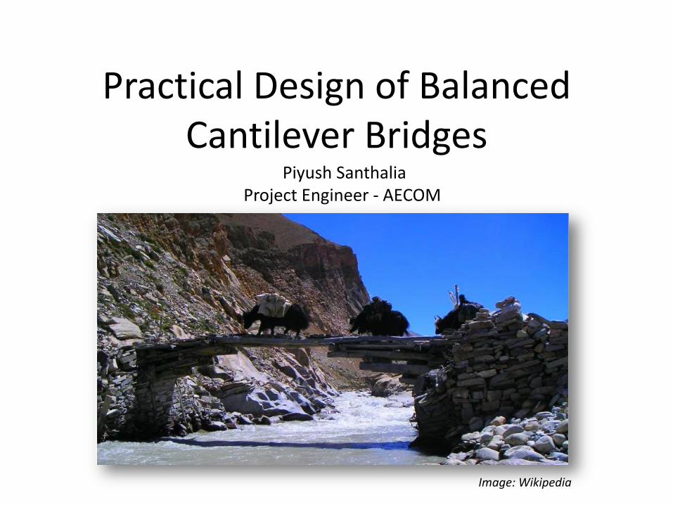
2. Longitudinal Span Configuration
• Typical 3 Span system – Mid Span: L
– End Spans: 0.6L to 0.7L (to control uplift in bearing)
L 0.6 L to 0.7L 0.6 L to 0.7L
• Typical 4 or more Span (varying) system 0.6 L1 to 0.7L1 L1 (L1 + L2)/2 0.6 L2 to 0.7L2
Piyush Santhalia
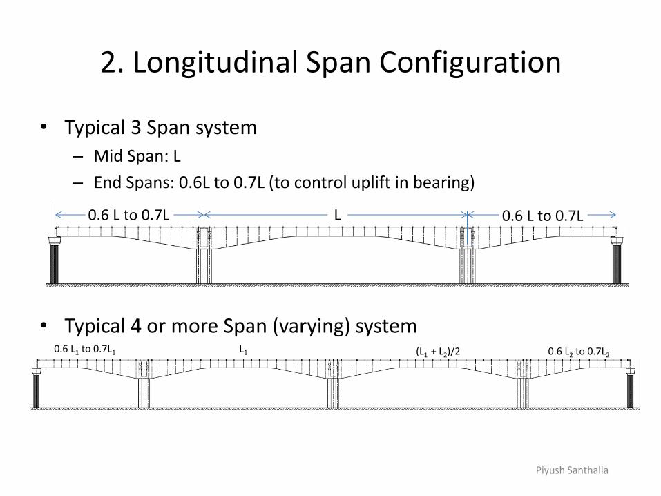
2. Longitudinal Span Configuration
• No such luxury in today’s congested urban area
I. 34 + 60 + 34 m
II. 60 + 60 m
III. 37 + 70 + 67 + 55 + 34m

Piyush Santhalia
3. Construction Sequence • Pier head : On ground supported staging
• Most of Segments: – Erect/cast using Segment Lifter/Form Traveller
– Cantilevered out from preceding segment.
– Prestressing tendons running one of the cantilever to the other are stressed.
– Symmetrical construction to minimize unbalanced moment on sub-structure and foundation: Balanced Cantilever
– Cast portion (beyond 0.5 x L) of both End-spans Ground Supported staging.
– Cast Stitch segments • Stitch in the End – span
• Stitch in the Mid-span
• Levels of the Cantilever arms being stitched should be matched
• Segmentation: 2.5m to 4m or even 5m – Construction Cycle
– Capacity of Form Traveller/Segment Lifter

Piyush Santhalia
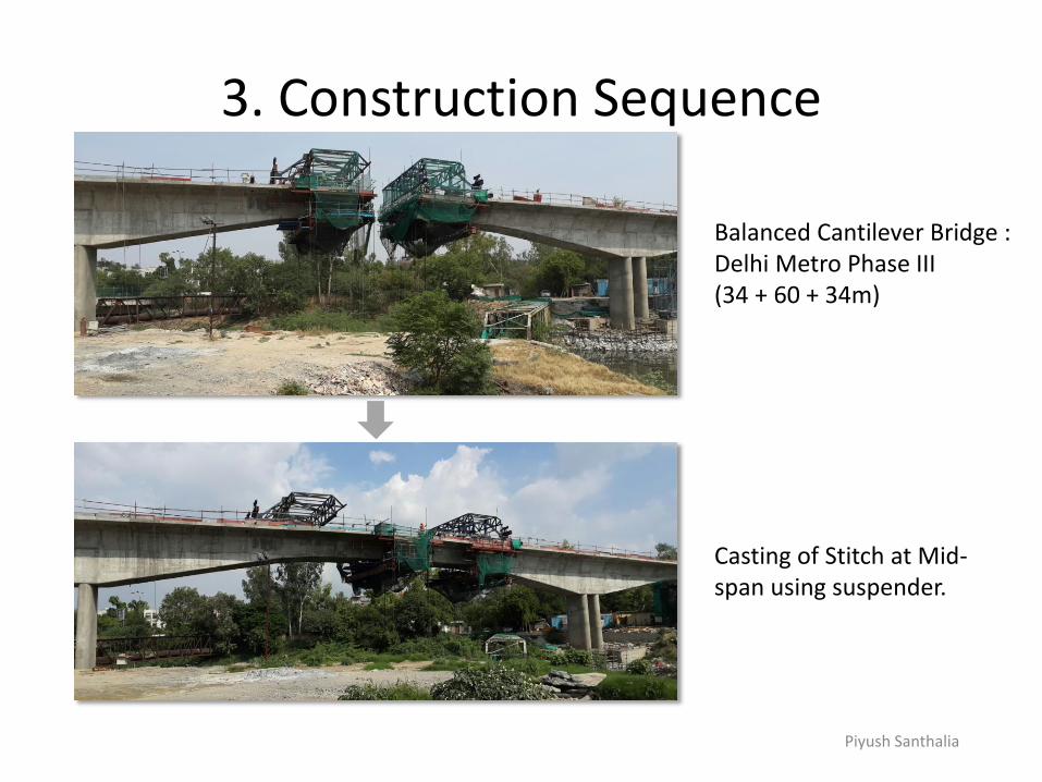
3. Construction Sequence
Balanced Cantilever Bridge : Delhi Metro Phase III 60 + 60m span
Piyush Santhalia
3. Construction Sequence
Casting of Stitch at Mid-span using suspender.
Balanced Cantilever Bridge : Delhi Metro Phase III (34 + 60 + 34m)
Piyush Santhalia
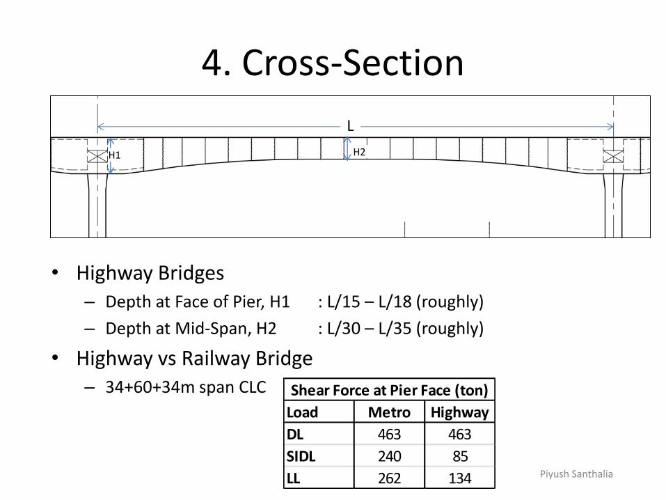
4. Cross-Section
L
H1 H2
• Highway Bridges – Depth at Face of Pier, H1 : L/15 – L/18 (roughly)
– Depth at Mid-Span, H2 : L/30 – L/35 (roughly)
• Highway vs Railway Bridge – 34+60+34m span CLC
Load Metro Highway
DL 463 463
SIDL 240 85
LL 262 134
Shear Force at Pier Face (ton)
Piyush Santhalia
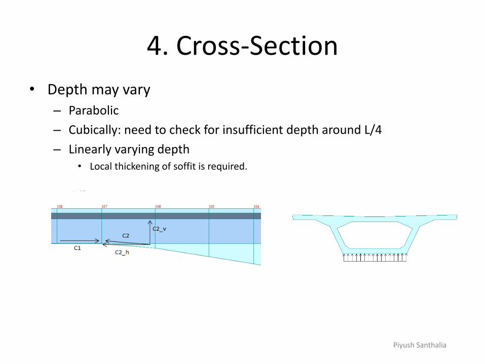
4. Cross-Section
• Depth may vary – Parabolic
– Cubically: need to check for insufficient depth around L/4
– Linearly varying depth • Local thickening of soffit is required.

Piyush Santhalia
5. Support Conditions
• Box Girder – On simple bearing – Stability check during construction
– Minimal secondary effect of Creep, Shrinkage and Prestressing
• Box Girder Integral with Intermediate Piers – Check pier for un-balanced moment during construction.
– Pronounced secondary effect.

Piyush Santhalia
6. Sub-Structure and Foundation
• Flexibility – High time period (lesser seismic force)
– Lower force due to secondary effects of creep, shrinkage and Prestressing Tendons
– Twin Piers
𝐹 =3𝐸𝐼
𝐿δ
Piyush Santhalia
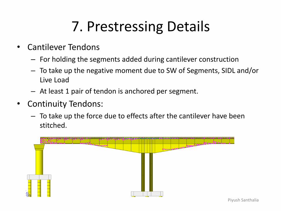
7. Prestressing Details • Cantilever Tendons
– For holding the segments added during cantilever construction
– To take up the negative moment due to SW of Segments, SIDL and/or Live Load
– At least 1 pair of tendon is anchored per segment.
• Continuity Tendons: – To take up the force due to effects after the cantilever have been
stitched.
Piyush Santhalia
7. Prestressing Details
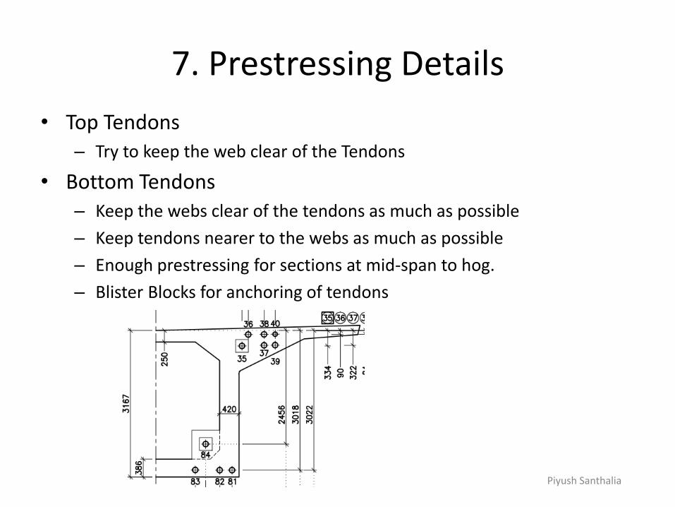
• Top Tendons – Try to keep the web clear of the Tendons
• Bottom Tendons – Keep the webs clear of the tendons as much as possible
– Keep tendons nearer to the webs as much as possible
– Enough prestressing for sections at mid-span to hog.
– Blister Blocks for anchoring of tendons

Piyush Santhalia
8. Analysis
• Why Construction Stage Analysis
Bending Moment Diagram due to SW: Simultaneous Analysis
Bending Moment Diagram due to SW: Sequential Analysis

Piyush Santhalia
8. Analysis
• Why Construction Stage Analysis
– Time Dependent Effects of Creep and Shrinkage • No secondary effect of Creep and Shrinkage before stitching
Structure before casting of stitch segment
Deformation due to Shrinkage.
Residual Shrinkage Strain: i) After 3 days – 4.3 x 10⁻⁴
ii) After 14 days – 2.5 x 10⁻⁴

Piyush Santhalia
8. Analysis
• Why Construction Stage Analysis
– Time Dependent Effects of Creep and Shrinkage • Different age of concrete at different loading
– Modulus of Elasticity increases with time
Piyush Santhalia
9. Design Check
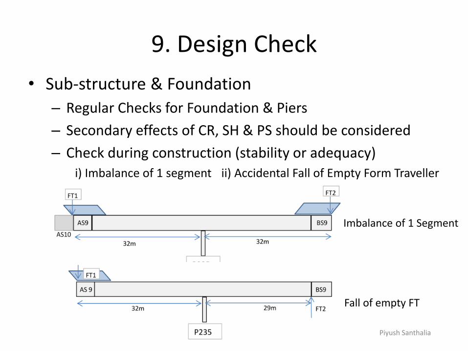
• Sub-structure & Foundation
– Regular Checks for Foundation & Piers
– Secondary effects of CR, SH & PS should be considered
– Check during construction (stability or adequacy) i) Imbalance of 1 segment ii) Accidental Fall of Empty Form Traveller
Imbalance of 1 Segment
Fall of empty FT
Piyush Santhalia
9. Design Check
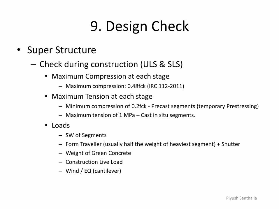
• Super Structure
– Check during construction (ULS & SLS) • Maximum Compression at each stage
– Maximum compression: 0.48fck (IRC 112-2011)
• Maximum Tension at each stage – Minimum compression of 0.2fck - Precast segments (temporary Prestressing)
– Maximum tension of 1 MPa – Cast in situ segments.
• Loads – SW of Segments
– Form Traveller (usually half the weight of heaviest segment) + Shutter
– Weight of Green Concrete
– Construction Live Load
– Wind / EQ (cantilever)

Piyush Santhalia
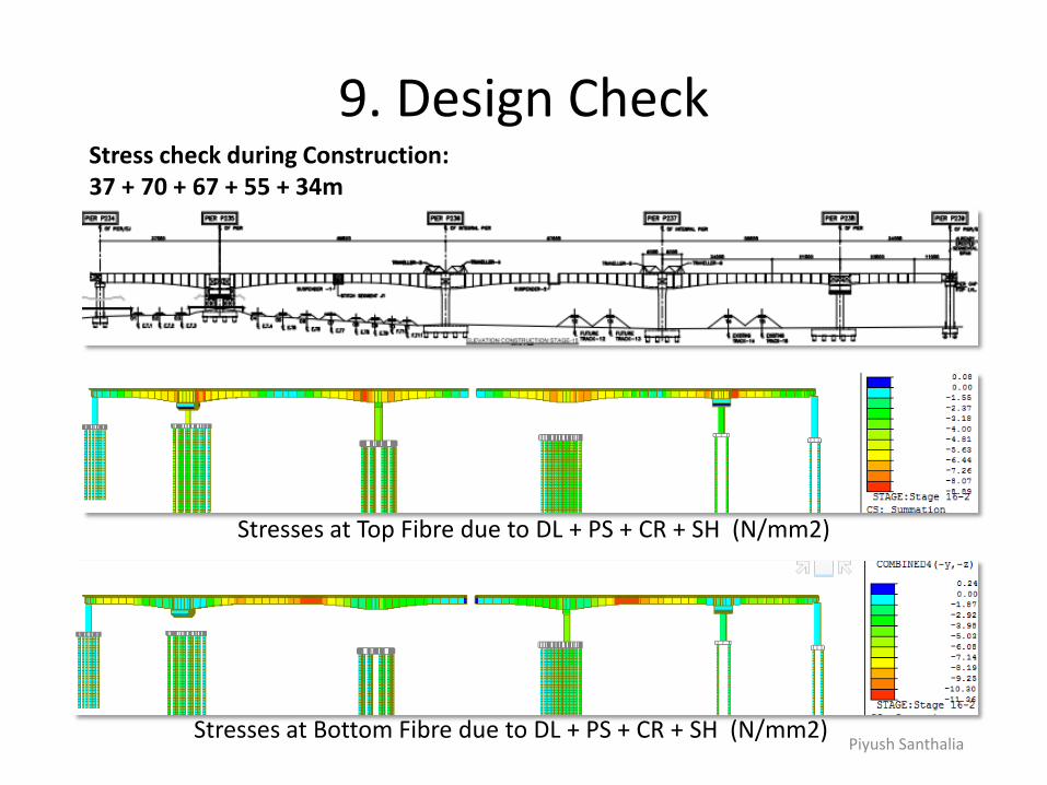
9. Design Check Stress check during Construction: 37 + 70 + 67 + 55 + 34m
Stresses at Top Fibre due to DL + PS + CR + SH (N/mm2)

Piyush Santhalia
9. Design Check
Stresses at Top Fibre due to DL + PS + CR + SH (N/mm2)
Stress check during Construction: 37 + 70 + 67 + 55 + 34m

Piyush Santhalia
9. Design Check
Stresses at Top Fibre due to DL + PS + CR + SH (N/mm2)
Stresses at Bottom Fibre due to DL + PS + CR + SH (N/mm2)
Stress check during Construction: 37 + 70 + 67 + 55 + 34m

Piyush Santhalia
9. Design Check
Stresses at Top Fibre due to DL + PS + CR + SH (N/mm2)
Stresses at Bottom Fibre due to DL + PS + CR + SH (N/mm2)
Stress check during Construction: 37 + 70 + 67 + 55 + 34m
Piyush Santhalia
9. Design Check
Stresses at Top Fibre due to DL + PS + CR + SH (N/mm2)
Stresses at Bottom Fibre due to DL + PS + CR + SH (N/mm2)
Stress check during Construction: 37 + 70 + 67 + 55 + 34m

Piyush Santhalia
9. Design Check
Stresses at Top Fibre due to DL + PS + CR + SH (N/mm2)
Stresses at Bottom Fibre due to DL + PS + CR + SH (N/mm2)
Stress check during Construction: 37 + 70 + 67 + 55 + 34m
Piyush Santhalia
9. Design Check
• Super Structure
– Check during Service (0 - Design life) • Loads
– Regular Loads (SW, SIDL, LL)
– Prestressing
» Losses up to design life should be considered
» Secondary effects are usually significant
– CR & SH: Secondary effects are significant.
– Temperature Variation
• SLS Checks – Maximum Compression
» Maximum compression: 0.48fck (IRC 112-2011)
– Maximum Tension
Piyush Santhalia
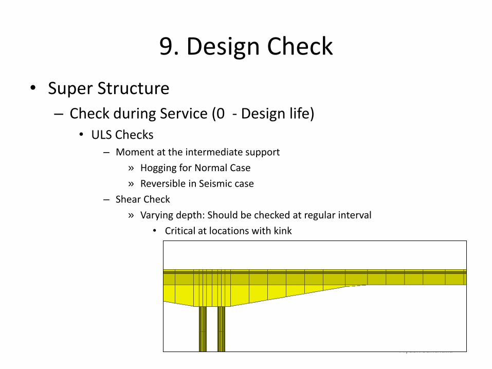
9. Design Check
• Super Structure
– Check during Service (0 - Design life) • ULS Checks
– Moment at the intermediate support
» Hogging for Normal Case
» Reversible in Seismic case
– Shear Check
» Varying depth: Should be checked at regular interval
• Critical at locations with kink

Piyush Santhalia
9. Design Check
• Super Structure
– Check during Service (0 - Design life) • ULS Checks
– Shear Check
» Vertical component of Prestressing: reduces shear
» Resal Effect: Part of Shear is balanced by the component of Normal force in the soffit slab.
Piyush Santhalia
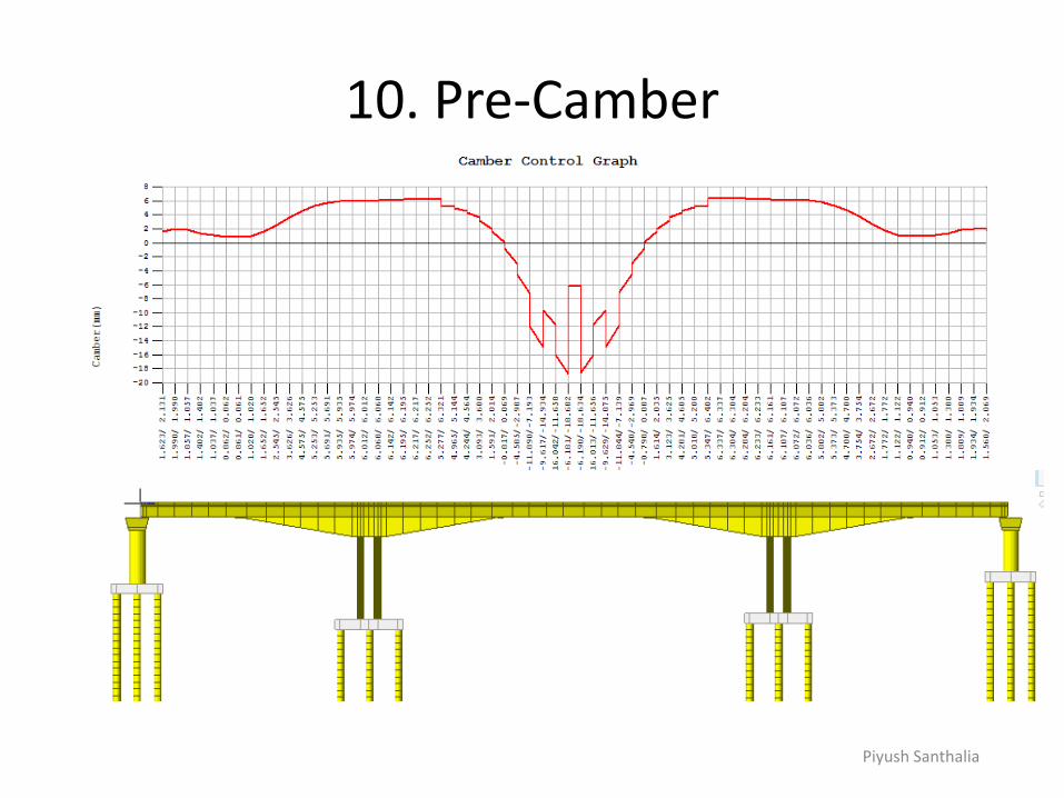
10. Pre-Camber

Piyush Santhalia
10. Pre-Camber
• Why pre-camber
– Under permanent loads the deck should have achieved the desired level.
• Desired Level at what time
– Concrete continues to sag/hog because of creep
– Achieving desired level at the end of design life: not logical

Piyush Santhalia
11. Modelling &other Suggestions
• For very wide or very deep section – Line Beam modelling: up to 20% error
• Shear Lag effect
• Difference in rates of shrinkage and drying creep because of different thicknesses of slabs.
• 3D model always yields larger deflections and larger Prestress losses
Ref: Excessive Long-Time Deflections of Prestressed Box Girders. I: Record-Span Bridge in Palau and Other Paradigms - Zdeněk P. Bažant, Qiang Yu and Guang-Hua Li
• Modelling of Piles
• Give concrete more time to gain strength before prestressing

Piyush Santhalia
THANK YOU Happy Designing