Embed Size (px)
Citation preview
Practical EMI Precompliance Test – with a CXA signal analyzer
Xiaowei Zhang
CXA/Value RF Product Line
Brand Manager
Mar 28, 2016

Page
How to evaluate EMI emissions with a
spectrum/signal analyzer ?

PageAgenda
– EMC Basics
– An introduction of regulatory standards
– The best practice during the product development cycle
2/5/2020
Update this text 3

Page
2/5/2020
Section 1 – EMI Basics
Customizable in Footer 4

Page
Getting started – Basic terms
Customizable in Footer
EMI, EMS, EMC
5
EMI
EMS
EMC
Today, We
focus
here !

Page
What is EMI?
– Wikipedia: EMI is disturbance
that affects an electrical circuit
due to either electromagnetic
conduction or
electromagnetic radiation
emitted from an external
source.
– EMI emissions can be well
captured by a spectrum
analyzer
– A spectrum analyzer tells you
the frequency, power, and other
important properties of an EMI
emission
Electromagnetic Interference
Conducted
Emissions
Conducted
Immunity
Radiated
Immunity
Radiated
Emissions
EMI Pre-Compliance

Page
EMI Phenomena
Customizable in Footer
Interference from motor circuit
7

Page
EMI Phenomena
Customizable in Footer
Interference from High speed digital circuit
8

Page
Sources of EMI (1/3)
• Natural sources below 10MHz are dominated by atmospheric noise generated by electrical storms.
- Lighting
• Above 10 MHz natural sources consist primarily of cosmic noise and solar radiation.
Natural Sources (also called radio-frequency interference or RFI)
EMI Pre-Compliance
9

Page
Sources of EMI (2/3)
• 2-way radio communication
• Cellular Phones
• Radio and TV broadcasters
• Internet Of Things (IoT)
• Oscillators
Intentional Man Made Sources
Caused by:
– Transmitted signal
• Intended transmission of a
frequency
• Sometimes called ‘On carrier’ or
‘Carrier frequency’
• A Continuous Wave (CW) signal
- Control Signal
- Beacon
• Modulated Signal
- Analog Voice or Data
- Digital Voice or Data
EMI Pre-Compliance

Page
Sources of EMI (3/3)
• Toaster ovens
• Bug zappers
• Hair dryers
• Electric Motors
• Etc.
Un-Intentional Man Made Sources
Caused by:
– Leakage
• RF frequency leaking out of an
enclosure
– Harmonics
• Multiples of a frequency
– Spurs
• Addition and subtraction of
frequencies can generate spurs
EMI Pre-Compliance
11

Page
3 elements in EMC
Customizable in Footer 12
Interference
source Propagation path
Victim
Radiated
Conducted
AC power network

Page
The impact of an EMI failure during the product development cycleMany manufacturers use (EMI) measurement systems to perform conducted and radiated EMI emissions evaluation prior to sending their product to a test facility for full compliance testing.
$ $ $ $
EMI Pre-Compliance
13
The cost of an EMI failure increases as the product development cycle moves on !

Page
Important !
Update this text
EMC evaluation is along with your product NPI cycle
14
2/5/2020
EMI Troubleshooting
EMI Pre-compliance
EMI Compliance

Page
2/5/2020
Section 2 - An introduction of regulatory standards
Customizable in Footer 15

Page
EMC standards
Customizable in Footer
From international to commercial
16
EMC Standards
International Commercial
IEC CISPR FCC ETS/EN GB
Basic Standards
• Provide general and fundamental rules
• Serve as a reference but not applicable to specific products
Generic Standards
• Provide essential test requirements and procedure in a specific environment
• Also provide limits
Product Standards
• Apply to specific products or families of products
• Provides test procedures and limits for these products
Categories:
CISPR
standard
Structure:

Page
– CISPR (Comité International Spécial des Perturbations Radioélectriques )
English: (Special International Committee on Radio Interference)
• A sub committee of the IEC (International Electrotechnical Commission)
• Determines and recommends required emissions and immunity:
- limits for products sold in the worldwide commercial market
- test equipment requirements
- test procedures/methodologies
CISPR Recommends Commercial Limits, Measuring Equipment and Methodologies
EMI Pre-Compliance

Page
– CISPR 11 - Industrial, Scientific, and Medical (ISM) Radio-Frequency Equipment
– CISPR 12 - Vehicles, Motorboats, and Spark-Ignited Engine-Driven Devices
– CISPR 13 - Sound and Television Broadcast Receivers and Associated Equipment
– CISPR 14 - Household Appliances, Electric Tools, and Similar Apparatus
– CISPR 15 - Electrical Lighting and Similar Equipment.
– CISPR 17 - Suppression Characteristics of Passive Radio Interference Filters and Suppression Components.
– CISPR 18 - Overhead Power Lines and High-Voltage Equipment
– CISPR 20 - Sound and Television Broadcast Receivers and Associated Equipment
– CISPR 21 - Interference to Mobile Radio communications
– CISPR 22 - Information Technology Equipment–Radio Disturbance Characteristics
– CISPR 24 - Information Technology Equipment–Immunity Characteristics
– CISPR 25 - Receivers Used on Board Vehicles, Boats, and on
– CISPR 32 – Multimedia devices emission testing (under development)
– CISPR 35 – Multimedia devices immunity testing (under development)
CISPR Product Groups
EMI Pre-Compliance
18

Page
Example of Products subject to CISPR 11 Testing
Customizable in Footer 19
T&M instruments
follows CISPR 11

Page
Examples of Products Subject to CISPR 14 Testing
EMI Pre-Compliance
20

Page
IEC/CISPRMeasurement Std. – CISPR 16
Equipment Std. – CISPR 16
Product Std. - CISPR 11-15, etc.
IEC 61XXX
GB
ANSI
FCC
CENELEC
EN
VCCI
Key Influencer - Commercial Regulations
EMI Pre-Compliance
21

PageEMI Pre-Compliance 22
Commercial EMC Standards and Entities - ExamplesCountry
/OrganizationEntity Standards
IEC CISPR CISPR Pub. xx
IEC TC77 IEC 6xxxx
EC CENELEC EN 550xx
US FCC, DoD FCC Part xx, MIL-STD. xxx
Canada CSA ICES xxx
Australia/NZ AS/NZS AS/NZS CISPR xx
Japan VCCI J550xx
China (Mainland)
CCC, MoD GB xxxx- xxxx
GJB xxx- xx (equivalent to Mil-STD)
Korea MIC Equivalent to EN 550xx
Taiwan BSMI CNS xxxx

Page
Which Standards to test against?
Three preliminary questions to answer when developing a product:
1. Where will the product be sold (for example, Europe, United States, Japan)?
2. What is the classification of the product?
a) Information technology equipment (ITE)
b) Industrial, scientific or medical equipment (ISM)
c) Automotive or communication
d) Generic (equipment not found in other standards)
3. Where will the product be used (for example home, commercial, light industry or
heavy industry)?
EMI Pre-Compliance
23
Depends on your product plan

Page
2/5/2020
Section 3 – EMI precompliance measurement overview
Customizable in Footer 24

Page
Example Radiated Emission Testing Environments
OATS ChambersBench Top – semi-anechoic
Definitions:
Anechoic Chamber → Room with no echoes; absorbers on all 6 sides
Semi-anechoic → Ground plane; reflection like OATS; correlation to OATS
OATS → Open Area Test Site
EMI Pre-Compliance
25

Page
EMI Measurement Units
– Conducted Emissions
⚫Commercial: dBμV
⚫Military: dBμA
– Radiated Emissions
⚫Electric field strength: dBμV/m
⚫Magnetic flux density: dBpT
Assuming a 50 ohm impedance, power measurement may be converted as follows:
dBμV = dBm + 107
dBm = dBμV – 107
dBμA = dBμV - 34
dBμA = dBm + 73
dBμV/m = dBμV + AF (Antenna Factor)
dBpT = dBμA /m + 2.0
/m=meter
pT= pico Teslas (magnetic flux density)
Many power converting tools available on-line
EMI Pre-Compliance 26

Page
Pre-compliance vs. Full Compliance Solutions
Pre-compliance Measurement Solutions:Evaluate the conducted and radiated emissions of a
device using correct detectors and bandwidths
before going to a test house for
compliance testing. Gives an approximation of the EMI
performance of the EUT
Full compliance testing requires an EMI receiver that
is tested to meet all CISPR 16-1-1 requirements.
Full Compliance Measurement Solutions:
EMI Pre-Compliance 27
Page
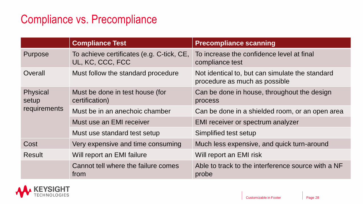
Compliance vs. Precompliance
Compliance Test Precompliance scanning
Purpose To achieve certificates (e.g. C-tick, CE,
UL, KC, CCC, FCC
To increase the confidence level at final
compliance test
Overall Must follow the standard procedure Not identical to, but can simulate the standard
procedure as much as possible
Physical
setup
requirements
Must be done in test house (for
certification)
Can be done in house, throughout the design
process
Must be in an anechoic chamber Can be done in a shielded room, or an open area
Must use an EMI receiver EMI receiver or spectrum analyzer
Must use standard test setup Simplified test setup
Cost Very expensive and time consuming Much less expensive, and quick turn-around
Result Will report an EMI failure Will report an EMI risk
Cannot tell where the failure comes
from
Able to track to the interference source with a NF
probe
Customizable in Footer 28

Page
About quasi-peak detection
– There are three commonly used detection modes for making EMI measurements,
including peak, average, and quasi-peak detection.
– Why use Quasi-peak detection?
• Used for CISPR based measurements.
• weighting signals as a function of repetition rate.
• Lower repetition rate noise has less “annoyance factor” and thus gets less emphasis
• CISPR bandwidth: 200 Hz, 9 kHz, and 120kHz bandwidth.
EMI Pre-Compliance
29

Page
Detection ModesPeak ≥ Quasi-Peak ≥ Average
EMI Pre-Compliance
30

Page
RBWs for CISPR & MIL
Commercial (CISPR)
Bands Frequency range CISPR RBW
A 9 – 150 kHz 200 Hz
B 150 kHz – 30 MHz 9 kHz
C 30 – 300 MHz 120 kHz
D 300 MHz – 1 GHz 120 kHz
E 1 – 18 GHz 1 MHz
Military (MIL-STD-461)
Frequency range RBW
30 Hz – 1 kHz 10 Hz
1 – 10 kHz 100 Hz
10 – 150 kHz 1 kHz
150 kHz – 30 MHz 10 kHz
30 MHz – 1 GHz 100 kHz
Above 1 GHz 1 MHz
Customizable in Footer 31

Page
Accessories of an EMI testing
Log Periodic Antenna:
200 to 1000 MHz
Tripods: used to raise and
lower antennas
Rotating Table:
To rotate EUT for testing
EUT: Equipment Under Test, same as Device Under Test (DUT)
Biconical Antenna:
30 to 300 MHz
Double ridged horn antennas
18 GHz or even higher
Hybrid log periodic
Broadband
30 MHz to 2 GHz
EMI Pre-Compliance
32

Page
More example items
Coupling and decoupling
network (CDN)
Current injection probe EM-Clamp
LISN: Line Impedance
Stabilization Network
Close Field Probe Set:
Diagnostics antennas
EMI Pre-Compliance
33

Page
EMI Measurements
EUT EUT Mains
Radiated
EmissionsConducted
Emissions
Keysight Equipment: X-series signal analyzers
LISN - (line impedance stabilization network)
LISN
Limiter
EMI Pre-Compliance

Page
Radiated Emissions Setup
EUT
Ground Plane
3 or 10 Meter distance
X-Series Signal Analyzer
with N6141C EMC App
The goal is to find and record the maximum emissions from the EUT by rotating the
turn table, changing the polarity and the height of the antenna.
Test in vertical and
horizontal position
1 to 4 m
above ground
plane
EMI Pre-Compliance
35

Page
About antenna factor (AF)
– AF is defined as the ratio of the electric field strength to the voltage induced across the
terminals of an antenna.
– For an electronic field antenna (V/m, or µV/m):
• Expressed in linear quantity: AF = 𝐸
𝑉(1/meter)
• Expressed in log quantity: AF = E dBμV/m – V dBμV
– For a magnetic field antenna (A/m):
•AF = ൗ9.37λ√𝐺
G: the antenna gain
Customizable in Footer
Very important in EMI measurement
36

Page
Conducted Emissions
Customizable in Footer
9 kHz – 30 MHz
37
Isolation
transformerAC
MainsLISN
DUT
Provide AC
power for DUT
Capture interference
signal for EMI receiver /
spectrum analyzer
Noise
(EMI)
Filter
Limiter
Spectrum analyzer / EMI receiver

Page
Environment setups for conducted emission test
Customizable in Footer
General practice
38
Table:
• Surface area > 1.5 * 1 m2
• Height > 0.8 m
• A metal grounding panel must be placed
on the surface of the table
Grounding panel:
• Size > 2*2 m2
• 0.5 m margin against the other setups
on the table
• Must connect to the ground
• Ground resistance < 2 ohm
Compliance test needs be done in a
shielded room

Page
2/5/2020
A flexible and low cost EMI Interference analysis tool –
CXA signal analyzer
Customizable in Footer 39
Page
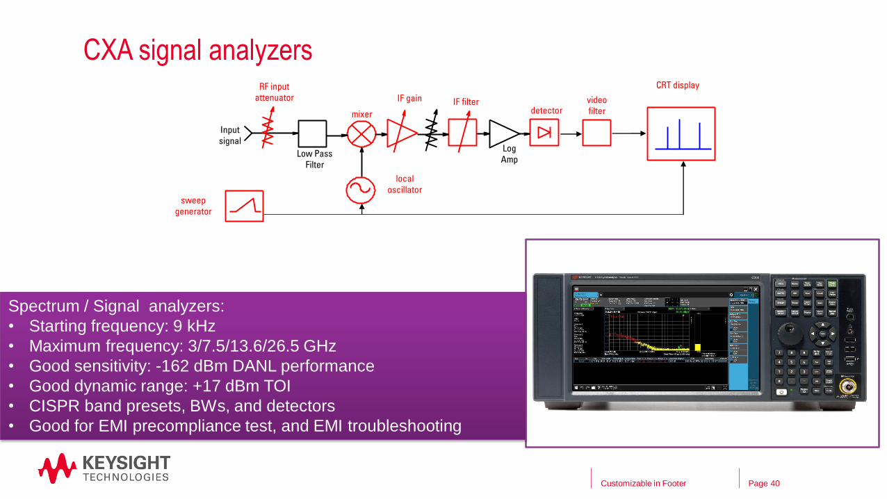
CXA signal analyzers
Customizable in Footer 40
Low Pass
Filter
Log
Amp
RF input
attenuator
mixer
IF filterdetector
video
filter
local
oscillatorsweep
generator
IF gain
Input
signal
CRT display
Spectrum / Signal analyzers:
• Starting frequency: 9 kHz
• Maximum frequency: 3/7.5/13.6/26.5 GHz
• Good sensitivity: -162 dBm DANL performance
• Good dynamic range: +17 dBm TOI
• CISPR band presets, BWs, and detectors
• Good for EMI precompliance test, and EMI troubleshooting

Page
N9000B option EMC
Customizable in Footer
Provides the essential capabilities on EMI interference analysis
41
N9000B-EMC option provides:
• CISPR 16-1-1 (2010) fully-
compliant detectors
• CISPR band presets to 18 GHz
• Measure at marker with three
detectors
• Tune and listen for signal
discrimination
• List price: $1,638
Measurement parameters set
according to CISPR bands
One-button EMI presets

Page
N9000B option EMC
Customizable in Footer
Measure at marker with 3 detectors simultaneously
42
Measure at marker with
three detectors:
• Peak
• Quasi-peak
• EMI average

Page
Built-in CISPR and MiL-STD limit line
Customizable in Footer
A list of commercial limits for recalling
43

Page
N6141C EMI measurement applicationRuns inside CXA signal analyzer
X-App Update FTD
Mar 2017
44
EMI precompliance test capabilities: • Built-in CISPR and Mil-STD compliant BW,
detectors and band presets
• Automated testing to regulatory limit lines with
user-selected margins
• Amplitude corrections for antennas, LISNs, NF
probes, etc
Measurement features: • 3 simultaneous detectors (Peak, Quasi-peak,
Average)
• Built-in signal list tracking those non-
compliance emissions
• Strip chart for analysis of emissions versus
time
• Supports precompliance “Click” measurementsOrdering info:
N9000B: Starting from $12,989
N6141C-2FP/2TP: $5,326 / $6,923
Page
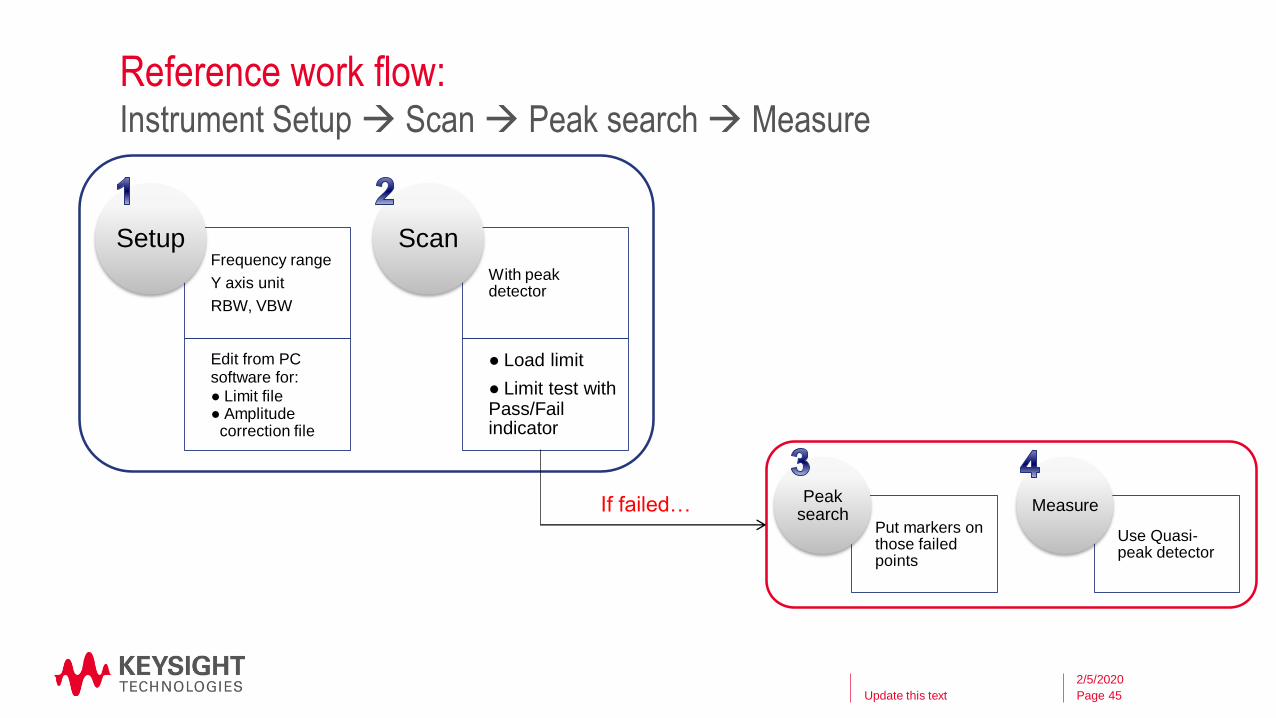
Reference work flow:
Update this text
Instrument Setup→ Scan → Peak search → Measure
45
2/5/2020
Frequency range
Y axis unit
RBW, VBW
Edit from PC software for:
● Limit file ● Amplitude
correction file
Setup
With peak detector
● Load limit
● Limit test with Pass/Fail indicator
Scan
Put markers on those failed points
Peak search
Use Quasi-peak detector
MeasureIf failed…

Page
N6141C Measurement procedure
Customizable in Footer
Step 1. Set up the scan table
46
1
2
Press [Meas Setup] →
{Scan table} to configure
the measurement range, as
well as other parameters, if
needed
The X-series signal
analyzer will set the EMI
measurement parameters
according to the scan table
automatically

Page
N6141C Measurement procedure
Customizable in Footer
Step 2. Load limit line. Load correction data.
47
1
2
• Press [Recall] → {Limit} to load a pre-
defined limit file
• Press [Recall] → {Correction} to load a
pre-defined correction file
To edit a correction, press [Input/Output] → {Correction}, to
manually edit correction data

Page
N6141C Measurement procedure
Customizable in Footer
Step 3. Scan, search, and measure
48
Capturing out of
limit emissions
and list them into
the table below
Measure each point with 3
detectors simultaneously,
also shows their
deviations from the limit
Strip chart lets you view
signals over a long time
period to identify widely
spaced discontinuities

Page
Wrap up
◆ 3 elements in EMC: interference source, propagation path, and the EMI sensitive device
◆ It is important to evaluate your new product’s EMI performance before you go to the test
house
◆ The conducted and radiated emissions can be captured and analysis with a spectrum
analyzer and corresponding accessories
◆ Spectrum analyzers help you on EMI precompliance test, and the EMI diagnostics
Understand the compromises/value in the precompliance scanning
It cannot duplicate the final compliance test, but it can tell you the EMI trend and the change of
trend in your device
Customizable in Footer
EMI basics and EMI measurement
49

Page
Ordering information
–N9000B CXA signal analyzer
• Option 503/507/513/526
• Option P03/P07/P13/P26
• Option EMC
Customizable in Footer 50
If you need more flexible and
comprehensive EMI analysis,
also order:
N6141C EMI measurement
application
For EMI diagnostic purpose, a
near field probe set is required.
Refer to N9311X-100 (H field)

Back up
Customizable in Footer 51

Page
Emissions regulationsComparison of regulatory agency requirements
EMI Pre-Compliance 52
25

Page
Emissions regulations in USFCC regulatory agency requirements
Note:
FCC part 15 states that any digital device which uses timing pulses (clocks) in excess of 9kHz, must not unintentionally
emit radiation over certain limits. This testing is required up to the 5th harmonic of the fastest clock but less than 40 GHz.
For example, a computer or radio with a 1.2 GHz processor must meet FCC Class B limits up to 6 GHz.
FCC Part 18 requires devices that operate (transmit) from 30 MHz to above 1Ghz test to 10th Harmonic, examples:
250 MHz 10th harmonic: 2.5 GHz
500 MHz 10th harmonic: 5.0 GHz
1.0 GHz 10th harmonic: 10 GHz
2.4 GHz 10th harmonic: 24 GHz
9 kHz – 30 MHz
EMI Pre-Compliance 53

Page
Source of EMI
Customizable in Footer 54
From Natural power:
• thunder; volcano, typhoon
• electrostatic discharge
• sun, outer space
• …
From Man-made Unintentional:
• Switching power supplies
• Switching frequencies and harmonics
• Load-dependent emissions
• Clock and Data
• High speed clocks, data, edges
• High speed interfaces
• Switching controls
• …
From Man-made Intentional:
• Broadcasting, cellular communication
• Radar, GPS
• Wireless charging
• …

Page
About Antenna type
Commercial electronics Automotive electronics Military
Frequency range 30 MHz – 1 GHz 10 kHz – 1 GHz 10 kHz – 18 GHz
Antenna type Biconical
Log periodic
Biconical
Log periodic
Whip antenna
Whip antenna
Biconical
喇叭天线
Customizable in Footer 55
Log periodic antenna Biconical antenna Whip antenna Horn antenna

Page
2/5/2020
Recommended design practices
Customizable in Footer 56

Page
Recommended Design Practices: Device Selection
• Use lowest clock speed possible.
• Use multiple clock oscillators instead of routing clock lines whenever possible.
• Use minimum acceptable rise-time parts.
• Use low-ESR , low - ESL capacitors for decoupling/filtering.
• Use multilayer PCBs whenever possible.
• Always use toroidal transformers in switching power supplies.
• Watch out for DC saturation of ferrites in power supply lines.
• Use SMT parts whenever possible.
• Avoid IC sockets whenever possible.
• Avoid using ribbon cables for data or clock signals.
• Keep cables as short as possible.
EMI Pre-Compliance
57

Page
Recommended Design Practices:PCB layout
• Segment board to separate high-frequency logic from low-frequency I/O as much as possible.
• Always route lines over ground/power plane "bridges" over segmentation "moats". The width of the bridges should extend at least 2 trace widths past outside traces.
• Ground the PCB to a metal plate parallel to it in a 2" grid. The ground plate should be as close to the PCB as possible, and should lip up to be higher than the PCB on the sides. The plate itself should be either the base of the enclosure or single-point grounded near the safety ("green-wire") ground attachment point.
• If a 2-layer board is used, fill one side with ground as much as possible, and eliminate as much trace work from that side as possible.
• Place decoupling capacitors as close to the IC Vcc and GND pins as possible -even on analog parts - we have seen Hall-effect sensor IC's oscillate at 40 MHz when no decoupling was used !
• Filters should always be place as close to the end of the trace as possible.
• I/O connector filters must go as close to the I/O port as possible; avoid ground planes between a common-mode filter and the connector it is filtering - the ground plane should stop at the circuit side of the CM choke.
• Buss lines, clock lines, and other periodic lines should be routed on layers adjacent to inner plane layers. Slower and low-susceptibility lines should be routed on outer layers.
• Always route clocks first and lock them. Avoid placing other lines within 2 trace widths of a clock line
• Ferrites and other filters should be reviewed to see if shapes can be used to allow replacement of the series elements with 0-ohm resistors at the prototype stage.
• Whenever possible, 45-degree bends should be used at corners.
• Minimize vias (connections between layers on a PCB).
• Do not route clock traces along edges of PCB or PCB segments.
• Allow at least 2 trace widths between edge-most trace and outside edge of power-plane.
• Treat Read/Write traces as clock traces.
EMI Pre-Compliance
58
Page
Recommended Design Practices: Mechanical design
• Try to provide an adjacent sheet metal plane with multiple attachments (every 2 inches recommended) to any PCB. Attachments (usually standoffs) should be short and wide as possible. If the product has a non-metallic enclosure, this "ground plate" is a requirement.
• Minimize longest side of any enclosure seam or opening. Greater than 2" is usually unacceptable.
• Allow for overlapping at seams.
• Do not allow paint to cover mating surfaces.
• Avoid dissimilar metals.
• All I/O connectors should be co-located.
• Avoid openings through which ESD can jump to electrical components. ESD can jump about 1/2 ", but can crawl almost 2" over plastic surfaces at 15kV.
• Ground all metal with short, wide ground bonds; the "green-wire" ground should not extend into the product interior more than 1.5".
• Avoid requiring large holes in PCB's.
• Allow for secure mounting of cables (up against metal whenever possible).
• Avoid long sections of metal which extend over electronics and are not grounded at short intervals.
• Use mechanical means for switches which would otherwise have long leads back to PCB.
• Avoid stacking PCBs or placing PCBs in parallel without having shielding wall in between.
• Avoid long lines to motors.
• Motor leads must be twisted, and should be run along metal as much as possible. Motors will usually require shielding.
• Review all sensor locations for ESD susceptibility. Sensor lines should be twisted and should be run along metal whenever possible.
• High-sensitivity analog circuitry will always require extremely tight shielding.
EMI Pre-Compliance
59