Embed Size (px)
Citation preview

HAL Id: hal-01055251https://hal.inria.fr/hal-01055251
Submitted on 12 Aug 2014
HAL is a multi-disciplinary open accessarchive for the deposit and dissemination of sci-entific research documents, whether they are pub-lished or not. The documents may come fromteaching and research institutions in France orabroad, or from public or private research centers.
L’archive ouverte pluridisciplinaire HAL, estdestinée au dépôt et à la diffusion de documentsscientifiques de niveau recherche, publiés ou non,émanant des établissements d’enseignement et derecherche français ou étrangers, des laboratoirespublics ou privés.
Distributed under a Creative Commons Attribution| 4.0 International License
Practical End-to-End Performance Testing Tool for HighSpeed 3G-Based Networks
Hiroyuki Shinbo, Atsushi Tagami, Shigehiro Ano, Toru Hasegawa, KenjiSuzuki
To cite this version:Hiroyuki Shinbo, Atsushi Tagami, Shigehiro Ano, Toru Hasegawa, Kenji Suzuki. Practical End-to-End Performance Testing Tool for High Speed 3G-Based Networks. 22nd IFIP WG 6.1 Interna-tional Conference on Testing Software and Systems (ICTSS), Nov 2010, Natal, Brazil. pp.205-220,�10.1007/978-3-642-16573-3_15�. �hal-01055251�

Practical End-to End Performance Testing Tool
for High Speed 3G-based Networks
Hiroyuki Shinbo1, Atsushi Tagami1, Shigehiro Ano1, Toru Hasegawa1,Kenji Suzuki2
1 KDDI R&D Laboratories Inc., 2-1-15 Ohara, Fujimino-shi,Saitama 356-8502, Japan
{shinbo, tagami, ano, hasegawa}@kddilabs.jp2 The University of Electro-Communications, 1-5-1 Chofugaoka, Chofu-shi,
Tokyo 182-8585, [email protected]
Abstract. High speed IP communication is a killer application for 3rdgeneration (3G) mobile systems. Thus 3G network operators should per-form extensive tests to check whether expected end-to-end performancesare provided to customers under various environments. An importantobjective of such tests is to check whether network nodes fulfill require-ments to durations of processing packets because a long duration of suchprocessing causes performance degradation. This requires testers (per-sons who do tests) to precisely know how long a packet is hold by vari-ous network nodes. Without any tool’s help, this task is time-consumingand error prone. Thus we propose a multi-point packet header anal-ysis tool which extracts and records packet headers with synchronizedtimestamps at multiple observation points. Such recorded packet headersenable testers to calculate such holding durations. The notable featureof this tool is that it is implemented on off-the shelf hardware platforms,i.e., lap-top personal computers. The key challenges of the implementa-tion are precise clock synchronization without any special hardware anda sophisticated header extraction algorithm without any drop.
Keywords: End-to-end Performance Tests, Clock Synchronization Protocol,Packet Header Analysis
1 Introduction
Providing high performances in the 3rd generation (3G) mobile systems whichhave begun being deployed is important for 3G mobile system operators. The1xEV-DO (1x Evolution Data Only) system based on the specification ofcdma2000 High Rate Packet Data [1] is an example of 3G mobile system andit uses a special data link protocol [1, 2]. The 3G mobile system operators (inthe rest of paper, we call them just 3G operators) extensively perform inter-operability tests [3], where end-to-end performances between a mobile terminaland a server are measured with various environments. In order to detect latentcauses of performance degradations before a commercial service begins, testers

2 H.Shinbo, A.Tagami, S.Ano, T.Hasegwa and K.Suzuki
(persons who do tests) of the 3G operators usually do the two tasks. First, ifperformance degradation is observed at the tests, they identify which software atwhich network node is the cause of degradation. Second, testers check whethernetwork nodes process a packet within the predefined duration or not. Thistesting is especially important for network nodes on the backbone because theyshould process it in a small duration, e.g., hundreds of micro-seconds, to providehigh end-to-end performances.
Since network nodes’ implementations are black-boxes to the 3G operators,the testers should capture packets at incoming/outgoing links of each networknode with timestamps and then calculate how long each packet is hold at thenetwork node by comparing the timestamps. However, this style of tests is verytime-consuming because such calculations should be manually performed for allpackets at all network nodes.
In order to automate such testers’ tasks, we propose a multi-point packetheader analysis tool which consists of IP packet header capture devices andthe manager. An IP packet header capture device captures IP packets from atapped link, extracts only IP packet headers and records them to its disk withtimestamps. The manager does calculations which the testers manually do bycontrolling all the IP packet header capture devices.
The main goal is that it is implemented on an off-the-shelf hardware platform.Actually we use a lap-top PC (Personal Computer) with a crystal oscillator,network interface cards and a RAM (Random Access Memory) disk instead ofusing expensive commercial packet tester such as IXIA [4]. This style of imple-mentation contributes not only to reducing costs of testing, but also to increasingchances of using such tools in various environments.
However, implementing it as user-space software on (lap-top) PCs is nottrivial. There are two key challenges for the implementation. The first and themost difficult challenge is clock synchronization with scores of micro-second levelprecision. Clocks, of which values are used as timestamps, of all PCs should besynchronized to calculate how long an IP packet is hold by a network node.Since a maximum holding duration of some network node is less than severalhundred milliseconds, i.e., about 400 micro-seconds, the maximum error amongthe clocks should be less than scores of micro-seconds. This precision is not easyto achieve without special hardware.
The second challenge is recording all IP packet headers to a RAM disk with-out any drop. Since an IP packet sent by either a server or a mobile terminal isencapsulated by PPP (Point-to-Point Protocol) and segmented by RLP (RadioLink Protocol) [1], the boundaries of captured packets do not always correspondto IP packet boundaries. Although the straight-forward way is to capture allpackets in order to bridge the gap, it is difficult for PCs to record a numberof 30 or 50 byte long packets segmented by RLP to its RAM disk without anydrop.
In this paper, we have developed a multi-point packet header analysis toolwhich is useful for end-to-end performance tests over 3G mobile systems. Thecontributions of are twofold: a simple and precise clock synchronization protocol
Practical End-to End Performance Testing Tool for 3G Networks 3
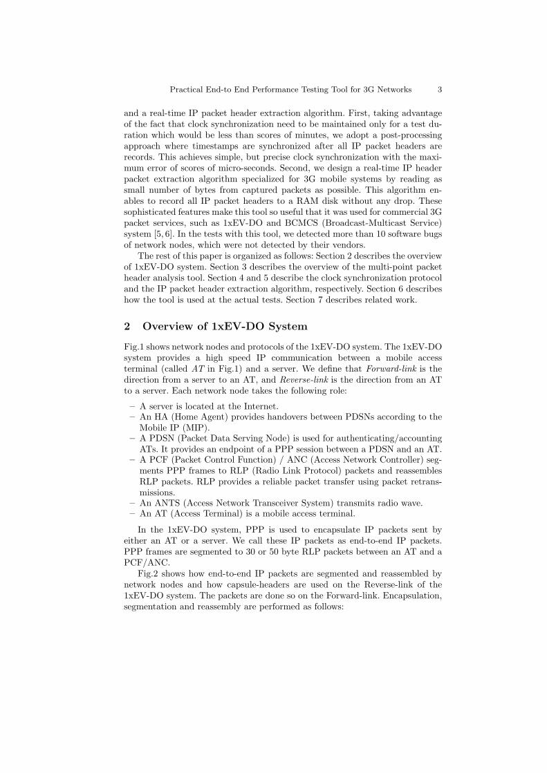
and a real-time IP packet header extraction algorithm. First, taking advantageof the fact that clock synchronization need to be maintained only for a test du-ration which would be less than scores of minutes, we adopt a post-processingapproach where timestamps are synchronized after all IP packet headers arerecords. This achieves simple, but precise clock synchronization with the maxi-mum error of scores of micro-seconds. Second, we design a real-time IP headerpacket extraction algorithm specialized for 3G mobile systems by reading assmall number of bytes from captured packets as possible. This algorithm en-ables to record all IP packet headers to a RAM disk without any drop. Thesesophisticated features make this tool so useful that it was used for commercial 3Gpacket services, such as 1xEV-DO and BCMCS (Broadcast-Multicast Service)system [5, 6]. In the tests with this tool, we detected more than 10 software bugsof network nodes, which were not detected by their vendors.
The rest of this paper is organized as follows: Section 2 describes the overviewof 1xEV-DO system. Section 3 describes the overview of the multi-point packetheader analysis tool. Section 4 and 5 describe the clock synchronization protocoland the IP packet header extraction algorithm, respectively. Section 6 describeshow the tool is used at the actual tests. Section 7 describes related work.
2 Overview of 1xEV-DO System
Fig.1 shows network nodes and protocols of the 1xEV-DO system. The 1xEV-DOsystem provides a high speed IP communication between a mobile accessterminal (called AT in Fig.1) and a server. We define that Forward-link is thedirection from a server to an AT, and Reverse-link is the direction from an ATto a server. Each network node takes the following role:
– A server is located at the Internet.– An HA (Home Agent) provides handovers between PDSNs according to the
Mobile IP (MIP).– A PDSN (Packet Data Serving Node) is used for authenticating/accounting
ATs. It provides an endpoint of a PPP session between a PDSN and an AT.– A PCF (Packet Control Function) / ANC (Access Network Controller) seg-
ments PPP frames to RLP (Radio Link Protocol) packets and reassemblesRLP packets. RLP provides a reliable packet transfer using packet retrans-missions.
– An ANTS (Access Network Transceiver System) transmits radio wave.– An AT (Access Terminal) is a mobile access terminal.
In the 1xEV-DO system, PPP is used to encapsulate IP packets sent byeither an AT or a server. We call these IP packets as end-to-end IP packets.PPP frames are segmented to 30 or 50 byte RLP packets between an AT and aPCF/ANC.
Fig.2 shows how end-to-end IP packets are segmented and reassembled bynetwork nodes and how capsule-headers are used on the Reverse-link of the1xEV-DO system. The packets are done so on the Forward-link. Encapsulation,segmentation and reassembly are performed as follows:

4 H.Shinbo, A.Tagami, S.Ano, T.Hasegwa and K.Suzuki
1. An application on an AT makes an end-to-end IP packet. The AT adds aPPP header to it and segments it to RLP packets.
2. The AT adds the RLP header to each segmented packet (S1 to S3), andtransmits them to an ANTS at a radio link.
3. After each segmented packet is received, the ANTS adds a UDP/IP headerand transmits it to a PCF/ANC.
4. The PCF/ANC removes the UDP/IP header and the RLP header. Then,the GRE/IP header is added to the segmented packets, and transmits thepackets to the PDSN.
5. The segmented packets are reassembled at a PDSN. The PDSN also checkswhether the IP packet is correctly reassembled or not by a CRC of the PPPheader.
6. The PDSN adds a MIP header to the IP Packet and transmits it to a HA.7. The HA removes the MIP Header and transmits the IP packet to a server.
Wired Link
Radio
Link
PPP
RLP
PHYPHY
HA Home Agent PDSN Packet Data Serving NodePCF Packet Control Function ANC Access Netowrk ControllerANTS Access Network Transceiver System AT Access Terminal
IP Internet Protocol MIP Mobile IPPPP Point to Point Protocol RLP Radio Link ProtocolPHY PHYsical layer
PHY
1xEV-DO system
Forward-link Reverse-link
ServerPDSN HAPCF/ANCANTS
PHY
AT
MIP
PHY
MIP
PHYPHY
IP
PPP
RLP
PHY
IP
PHY
Fig. 1. Network Nodes and Protocols in 1xEV-DO system
3. Add UDP/IP
header and
transmit
IP Packet
S1 S2 S3
PPP
Header
PDSN
IP Packet
6. Add MIP header and transmit
MIP Header
HA
IP Packet
7. Remove MIP
Header and
transmit to server
Radio
Link
Wired
LinkWired
Link
Wired
Link
IP Packet
S1 S2 S3
S1
S2
S3
RLP
Header
PPP
Header
2. Add RLP
Header and
transmit
AT
1. Segment
S1
S2
S3
,
/IP
4. Remove
UDP/IP and RLP header
add GRE
header and
transmit
GRE/IP Header
/PCF ANC
S1
S2
S3
UDP/IP Header
ANTS
5. Reassmble
Fig. 2. Overview of segmenting and reassembling and used headers

Practical End-to End Performance Testing Tool for 3G Networks 5
3 Multi-point Packet Header Analysis Tool
3.1 Overview
The structure of multi-point packet header analysis tool is illustrated in Fig.3.It consists of IP packet header capture devices and the manager. In the restof paper, we call the multi-point packet header analysis tool as the analysis
tool, and an IP packet header capture device as a capture device. We implementthem as the user-space software running a PC with a crystal oscillator, networkinterface cards and RAM disk.
NotePC with AT
CaptureDevice
CaptureDevice
CaptureDevice
ObservationPoint
Manager
Control Network
Multi-point Packet Header Analysis Tool
CaptureDevice
ObservationPoint
ObservationPoint
PCF/ANCANTS PDSN HA
Server
Observation
Point
Fig. 3. Multi-point Packet Header Analysis Tool
Each capture device is a lap-top PC with two network interface cards. Onenetwork interface card is used to tap a link and the other is used to communicatewith the manager. Capture devices are set to tap links between all pairs ofnetwork nodes including a server and an AT. We call tapped links as observationpoints. A capture device extracts an end-to-end IP packet header from a capturedpacket and records it into its RAM disk with a timestamp when the packet iscaptured. On the contrary, the manager controls capture devices and analyzesall captured IP packet headers collected from them.
3.2 How Analysis Tool is Used?
How this tool is used to analyze a communication flow between the AT and theserver is as follows:

6 H.Shinbo, A.Tagami, S.Ano, T.Hasegwa and K.Suzuki
Preparation for Clock SynchronizationBefore the AT and the server start communicating, the manager broadcasts apacket for synchronizing the capture devices’ clocks to that of one the capturedevices. All capture devices are connected via a broadcast medium such asEthernet.
Packet Header ExtractionA tester makes all capture devices start capturing packets from tapped links.When a packet is captured, each capture device extracts an end-to-end IP packetheader and then records it to its local RAM disk with its timestamp. The time-stamp is read from the clock of PC which is a crystal oscillator. How the real-time IP packet header extraction algorithm handles protocol headers of capturedpackets will be described in Section 5.
Packet Holding Duration AnalysisAfter the test communication finishes, the manger collects all headers from allthe capture devices. The timestamps set by individual capture devices are syn-chronized to the clock of one of the capture device. In other words, all timestampsare re-written so as to be synchronized to such device’s clock. How clocks are syn-chronized will be described in Section 4. Then by analyzing timestamps for thesame end-to-end IP packet at difference observation points, a tester calculateshow long each end-to-end packet is hold by each network node.
4 Clock Synchronization Protocol
4.1 Problem Statement
The required precision should be around scores of micro-seconds. This is be-cause the PDSN and the HA, i.e., backbone network nodes, handle a numberof communication flows between ATs and servers. Usually, these network nodesshould process each end-to-end IP packet within less than hundreds of micro-seconds. In some system, the average duration of processing a packet is about400 micro-seconds as described in Section 6. Thus the goal of the maximum erroris within scores of micro-seconds.
In order to precisely explain our clock synchronization protocol, we defineseveral terms. A clock is a hardware register of a PC and its value is createdfrom its crystal oscillator. A clock value is how many the crystal oscillator ticksand corresponds to the elapsed time. We use a time value and a timestampinterchangeably as a clock value. When a clock value is set to a captured packet,we call it is a timestamp. A clock frequency is how many it ticks in one second.Clock synchronization or synchronizing clocks means that difference betweenclock values of different capture devices are less than some threshold. For exam-ple, if the difference is always less than 100 micro-seconds, clocks are said to be100 micro-seconds precise or the maximum error is within 100 micro-seconds.

Practical End-to End Performance Testing Tool for 3G Networks 7
4.2 Hurdles to Prevent Clock Synchronization
The goal of clock synchronization protocol is to synchronize all clocks of capturedevices to a selected capture device, which we call it the master capture device,within scores of micro-second error. The protocol consists of the two procedures.First, the manager broadcast a packet informing all capture devices of clockvalues being set to 0 (initialization). During the test, each capture device readsits clock value and sets it as a timestamp to a captured IP packet header. Second,after the test, timestamps at different capture devices are compensated so thatthe clocks are synchronized.
There are two factors which prevent the clocks from being synchronized.
Long-term and Short-term Errors of Crystal OscillatorsA crystal oscillator is not either accurate or stable. Each oscillator’s frequency isdifferent from the ideal frequency. The difference is called the frequency error andthat in most PCs is accurate to one part in 104 to 106. Besides, its frequencychanges due to environmental factors such as variations in temperature andsupply voltage. Due to frequency errors between two devices, the clock valuesare gradually drifting as shown in Fig.4. The x-axis and y-axis show the idealtime and the time observed at the ideal clock or the actual clock. The idealclock means a clock without any frequency error. The dotted line shows howthe ideal clock advances, and the angle is 45 degree. The observed time valuesof the actual clock are plotted and they are interpolated to the line using theleast squares method. The angle difference between the two lines corresponds tothe average frequency error. Since this angle or the difference is stable for a longduration, we call it a long-term error. On the contrary, the plots are not alwayson the interpolated line. A short term error is a difference between the observedtime value of the actual clock and the dotted line.
Time
Ob
se
rve
d T
ime
Idea
l Clock
Each Observation
Short-term
Error
Actual Clock
Long-term
Error
Fig. 4. How Ideal and Actual Clocks Advance

8 H.Shinbo, A.Tagami, S.Ano, T.Hasegwa and K.Suzuki
Non-deterministic Delay of Initialization Packet TransferAt the initialization, the manger broadcast a packet for setting all clock valuesto 0. However, the packet does not always reach capture devices at preciselythe same time. In other words, delay of sending the packet from the managerto each capture is not deterministic due to several non-deterministic delays: thetime spent by the manager, the delay incurred waiting for access to a physicalinterface card, the time needed for a packet from the manager to a capturedevice, and the time required for the capture device’s network interface cardto receive and notify the user space software of its arrival. Due to such non-deterministic delays, the ideal time of capture device is different from that ofthe master capture device.
4.3 Design Principles
We set out the two design principles to compensate for the two factors.
Compensating for Clock’s Long-term ErrorWe assume that the duration of each test is less than 20 minutes. We choose 20minutes because it is recommended that TCP performance tests should continuemore than 15 minutes. Due to such a short duration, we can assume that ahardware clock is stable for the duration and that we can ignore the short termerror. By assuming that all clocks are stable, we can easily synchronize the clocksby compensating for the angle difference from the capture device to the masterone.
Compensating for Non-deterministic Delay with BroadcastCommunicationWe compensate for non-deterministic delays using the broadcast media. Capturedevices, which are usually located at an in-house test-bed, are directly connectedeach other via a broadcast medium so that a packet sent for synchronizingclocks are received by all the capture devices at almost the same time.
4.4 Preliminary Measurements of Long-term and Short-term Errors
How the design principles work well depends on how long-term and short-termerrors of actual crystal oscillators are, how stable they are and how the packetdelays of the actual broadcast medium are. Thus we have measured them in thefollowing experimental conditions:
– A packet tester, e.g., IXIA 400 [4], is used to broadcast a 40 byte long testpacket every second for 20 minutes. The clock’s precision of the packet testeris 1 PPM (Part Par Million).
– A shared Ethernet hub is used as a broadcast medium.– Two PCs, which run Linux (kernel 2.4.18), are set at the broadcast medium
and capture the test packets using tcpdump software [7]. Tcpdump runs inthe user space and sets a timestamp to every captured packet.

Practical End-to End Performance Testing Tool for 3G Networks 9
– This 20 minutes experiment was performed 10 times and thus 20 measure-ment results for a clock were totally obtained.
Clock’s Long-term and Short-term ErrorsTwo typical measurement results are shown in Fig.5. The x-axis is the clock value(the time value) at the packet tester and the y-axis is the error from the clockvalue at the PC (PC1 or PC2) from that of the packet tester. We interpolateall the errors from the clock values to the lines with the least squares method.Among the 20 measurement results, 19 measurements show that the clock wasstable for the 20 minutes. This result is shown by the line with caption PC1
in Fig.5. All the errors are almost on the interpolated line. On the contrary,at one measurement, the clock was not stable, i.e., the clock frequency changesduring the 20 minutes. This result is shown by the line with caption PC2 inFig.5. The angle of interpolated line of PC2 changes when 445 seconds elapsesat the packet tester. Since the error of PC2 increases to about 300 micro-secondsafter 20 minutes elapse, it is difficult to make the error at any time less than 100micro-seconds only by compensating for the angles of the interpolated lines.
-0.3
-0.25
-0.2
-0.15
-0.1
-0.05
0
Err
or
[s]
Time [s]
PC1
PC2
Fig. 5. Timestamps at the Two PCs
Due to this, we adopt an approach that results of a test during when suchclock unstableness is detected are thrown away and the test is retried.
Besides, we calculate all the short-time errors, i.e., the distances from all themeasured clock values to the interpolated lines. The maximum short-time erroris about 20 micro-seconds. Since the long-duration error would become almost0 by compensating for the angle differences, this 20 micro-seconds level erroris not a problem to synchronize clocks within the maximum error of scores ofmicro-seconds.
Non-deterministic DelayWe cannot correctly measure how long the difference between the delays fromthe packet tester to each PC is. However, the above maximum 20 micro-secondserror includes both the short-term clock error and the above difference. Thus

10 H.Shinbo, A.Tagami, S.Ano, T.Hasegwa and K.Suzuki
it is estimated that the maximum difference is less than 20 micro-seconds. Itmeans that the differences between start times at different PCs are less than 20micro-seconds. As the result, the error of clocks would be less than twice as 20micro-seconds, i.e., 40 micro-seconds during 20 minutes.
4.5 Protocol Details and Performance
This subsection describes the details of the clock synchronization protocol. It isassumed that there are n capture devices numbered from 0 to n − 1 and themaster capture device is 0.
1. The manager broadcasts m broadcast packets Ps = {Ps1, Ps2, . . . , Psm}to all capture devices at equal intervals via the broadcast medium.Each capture device k records the clock values when it received Ps asts(k) = {ts1(k), ts2(k), . . . , tsm(k)}.
2. When the test starts, the capture device k reads its clock value and recordsit as a timestamp of captured IP packet header. The timestamp of the i thIP packet header is denoted as tk(i).
3. After the test finished, the manager broadcasts m broadcast packetPe = {Pe1, Pe2, . . . , Pem} to all capture devices at equal intervals via thebroadcast medium. Each capture device k records the clock values when itreceived Pe as te(k) = {te1(k), te2(k), . . . , tem(k)}.
4. The manager calculates angles of the clock values before and after the test,i.e., ts(k) and te(k), using the least squares method. If the difference betweenthe calculated angles is larger than the predefined threshold th such thatAngle(ts(k))−Angle(te(k)) ≥ th , the frequency error of capture device i islarger than the predefined threshold. The clock of capture device k cannotbe synchronized to the master capture device 0. The clock synchronizationprotocol stops. (As the result, the test result would be thrown away and thistest would be re-tried again.)
5. The manager rewrites timestamp tk(i) to tk(i) according to Equation(1),and ts1(0), tem(0) are the clock values of the first and the last packets re-ceived by the master capture device. (All timestamps of capture device k
are synchronized to those of the master capture device 0.) This rewrite isperformed for all the capture devices except for the master capture device 0.
tk(i) = ak · tk(i) + bk (1)
where
ak =ts1(0)− ten(0)
ts1(k)− ten(k), bk =
ts1(k) · (ten(0)− ts1(0))
ts1(k)− ten(k)
We applied the clock synchronization protocol to the 10 experiments de-scribed in Section 4.4. PC1 and PC2 are regarded as a capture device and themaster capture device, respectively. For the 10 experiments, the maximum er-ror after clock synchronization is about 16.8 micro-seconds for 9 experiments.
Practical End-to End Performance Testing Tool for 3G Networks 11
At one experiment, the clock synchronization protocol stops. (This correspondsto the case that the clock frequency changes after 445 seconds elapse in Fig.5.)This result shows that our clock synchronization protocol can synchronize clockswithin an error of scores of micro-seconds. This definitely fulfills the tool’s re-quirement, i.e., the maximum effort within scores of micro-seconds.
5 End-to-end IP Packet Header Extracting Algorithm
5.1 Design Principles
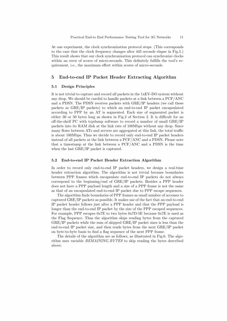
It is not trivial to capture and record all packets in the 1xEV-DO system withoutany drop. We should be careful to handle packets at a link between a PCF/ANCand a PDSN. The PDSN receives packets with GRE/IP headers (we call thesepackets as GRE/IP packets) to which an end-to-end IP packet encapsulatedaccording to PPP by an AT is segmented. Each size of segmented packet iseither 30 or 50 bytes long as shown in Fig.2 of Section 2. It is difficult for anoff-the-shelf PC with tcpdump software to record a number of small GRE/IPpackets into its RAM disk at the link rate of 100Mbps without any drop. Sincemany flows between ATs and servers are aggregated at this link, the total trafficis about 100Mbps. Thus we decide to record only end-to-end IP packet headersinstead of all packets at the link between a PCF/ANC and a PDSN. Please notethat a timestamp at the link between a PCF/ANC and a PDSN is the timewhen the last GRE/IP packet is captured.
5.2 End-to-end IP Packet Header Extraction Algorithm
In order to record only end-to-end IP packet headers, we design a real-timeheader extraction algorithm. The algorithm is not trivial because boundariesbetween PPP frames which encapsulate end-to-end IP packets do not alwayscorrespond to the beginning/end of GRE/IP packets. Besides a PPP headerdoes not have a PPP payload length and a size of a PPP frame is not the sameas that of an encapsulated end-to-end IP packet due to PPP escape sequences.
The algorithm finds boundaries of PPP frames as small number of accesses tocaptured GRE/IP packets as possible. It makes use of the fact that an end-to-endIP packet header follows just after a PPP header and that the PPP payload islonger than the end-to-end IP packet by the size of the PPP escaped sequences.For example, PPP escapes 0x7E to two bytes 0x7D-5E because 0x7E is used asthe Flag Sequence. Thus the algorithm skips reading bytes from the capturedGRE/IP packets while the sum of skipped GRE/IP packet sizes is less than theend-to-end IP packet size, and then reads bytes from the next GRE/IP packeton byte-to-byte basis to find a flag sequence of the next PPP frame.
The details of the algorithm are as follows, as illustrated in Fig.6. The algo-rithm uses variable REMAINING BYTES to skip reading the bytes describedabove.

12 H.Shinbo, A.Tagami, S.Ano, T.Hasegwa and K.Suzuki
1. The algorithm captures a GRE/IP packet.2. Bytes of the captured GRE/IP packet are read on byte-to-byte basis until
finding Flag Sequence (0x7E) of a PPP frame. After finding Flag Sequence,it goes to 3. Otherwise, it goes to 1.
3. “Protocol” field in the PPP header is checked. If “Protocol” field is IP packet,it goes to 4. Otherwise, since this PPP frame is not IP packet, it goes to 2for finding the next PPP frame.
4. It obtains an end-to-end IP packet length by reading an IP packet lengthfield of an end-to-end IP packet header just after the PPP header. If thecurrent GRE/IP packet does not include the IP packet length field, thenext GRE/IP packet is read on byte-to-byte basis until finding the IPpacket length field. Then, the end-to-end IP packet length is set to vari-able REMAINING BYTES.
5. When the next GRE/IP packet is captured, it checks the payload size ofthe GRE/IP packet. If the payload size is less than REMAINING BYTES,the end of current PPP frame does not exist in this GRE/IP packet. In thiscase, REMAINING BYTES is decreased by the payload size of this GRE/IPpacket, and it repeats this procedure. Otherwise, since there is the end ofthe current PPP frame in this GRE/IP packet, it goes to 6.
6. Bytes of the captured GRE/IP packet are read on byte-to-byte basis un-til finding Flag Sequence as the end of the current PPP frame. Then, itputs the end-to-end IP packet header information with this GRE/IP packettimestamp to a RAM disk, and it goes to 2.
S6
IP Packet1
S1 S2 S3
IP Packet2
S4 S5
IP Header
PPP
HeaderIP Packet3
S7 S8
Segmented packets
(=payload of GRE/IP packets)
Finds PPP Flag sequence, and
gets an end-to-end IP packet length from IP header.
End-to-end IP packets
Skip REMAINING_BYTESbased on the obtained end-to-end IP
packet length.
Fig. 6. End-to-end IP Packet Header Extraction Algorithm
We have measured performances of our algorithm recording only IP packetheaders and the tcpdump software recording packets. The traffic is collected fromthe real 1xEV-DO system. Tcpreplay [8] is used to replay the collected traffic withvarious rates. The performance tests are performed using PCs with GbE (Giga

Practical End-to End Performance Testing Tool for 3G Networks 13
bit Ethernet) network interface cards. The number of transmitted packets is7,119,000 (1,228Mbytes), which includes 1,547,000 end-to-end IP packets. Table1shows the numbers of end-to-end IP packets correctly recorded by tcpdump, andthe numbers of end-to-end IP packet headers recorded by our algorithm. Theperformance of our algorithm is better than that of tcpdump. Our algorithm didnot drop any end-to-end IP header even for 120 Mbps traffic. On the contrary,the tcpdump software dropped some end-to-end IP packets.
Table 1. How many Packets/Headers are recorded?
Traffic 80Mbps 100Mbps 120MbpsPacket per sec 63kpps 79kpps 96kpps
tcpdump 1546963 1539242 1541213(99.9%) (99.50%) (99.62%)
Our algorithm 1547000 1547000 1547000(100%) (100%) (100%)
Note: The percentage means the ratio of how many packets (tcpdump) or headers (ouralgorithm) are recorded.
6 Actual Tests with the Developed Tool
We applied the analysis tool to tests of the BCMCS system which providesmulticast packet delivery to ATs using forward-links of the 1xEV-DO system.The network nodes and protocol stacks are those of Fig. 1 except for that MIPand HAs are not used. Important requirements to the BCMCS system are thatthe number of lost packets should be as small as possible and that every packetshould be processed by the PDSN within hundreds of micro-seconds. The mainobjections of these tests are to check whether the PCF/ANC and the PDSNsatisfies the above requirements under the condition that radio-link’s quality isgood and that no congestion occurs at the backbone network.
We conducted about 50 test scenarios in this environment. At each scenario, aserver sends multicast packets to ATs at various sending rates. In order to checkhow long each packet is process at network nodes, we set capture devices at thelink between the server and the PDSN (observation point 1), the link betweenthe PDSN and the PCF/ANC (observation point 2) and the AT (observationpoint 3).
During the tests, we found more than 10 software bugs of the PDSN and thePCF/ANC. The bugs are classified into two bugs. Fig.7 (a) and (b) show typicalexamples of these two. Please note that several packets are received by the ATat the same time in Fig.7 (a) and (b) because such packets are encoded using
14 H.Shinbo, A.Tagami, S.Ano, T.Hasegwa and K.Suzuki
Between
Server and PDSN
Between
PDSN and PCF /ANCat AT
Num Timestamp#1 18.057512 [s]
#2 18.077513 [s]
#3 18.097514 [s]
#4 18.117515 [s]
#5 18.137516 [s]
#6 18.157522 [s]
#7 18.177521 [s]
#8 18.197521 [s]
#9 18.217524 [s]
#10 18.237525 [s]
Timestamp
18.057828 [s]
18.077814 [s]
18.097887 [s]
18.117819 [s]
18.137816 [s]
18.157890 [s]
18.177821 [s]
18.197818 [s]
18.217890 [s]
18.237831 [s]
Timestamp
24.329193 [s]
24.339208 [s]
24.399295 [s]
The Packet #1 to #4
are not observed at
Observation Point 3..
Num Timestamp#1 26.788076 [s]
#2 26.808077 [s]
#3 26.828079 [s]
#4 26.848082 [s]
#5 26.868082 [s]
#6 26.888084 [s]
#7 26.908085 [s]
Timestamp26.788469 [s]
26.808437 [s]
26.828401 [s]
26.848446 [s]
26.888460 [s]
26.908521 [s]
26.869917 [s]
#135 29.568257 [s]
#136 29.588258 [s]
#137 29.618265 [s]
#138 29.638267 [s]
#139 29.658268 [s]
#140 29.678269 [s]
#141 29.698271 [s]
29.568667 [s]
29.588627 [s]
29.618704 [s]
29.638577 [s]
29.658639 [s]
29.698620 [s]
29.686023 [s]
Timestamp
33.011773 [s]
33.081875 [s]= =
=
35.715691 [s]
35.785793 [s]
=
Delay
393[us ]
360[us ]
322[us ]
364[us ]
1835[us]
376[us ]
436[us ]
410[us ]
369[us ]
439[us ]
310[us ]
371[us ]
7754[us]
349[us ]
(a) Lost packets (b) Longer delay
Between
Server and PDSN
Between
PDSN and PCF /ANCat AT
ObservationPoint 1
ObservationPoint 1
ObservationPoint 2
ObservationPoint 2
ObservationPoint 3
ObservationPoint 3
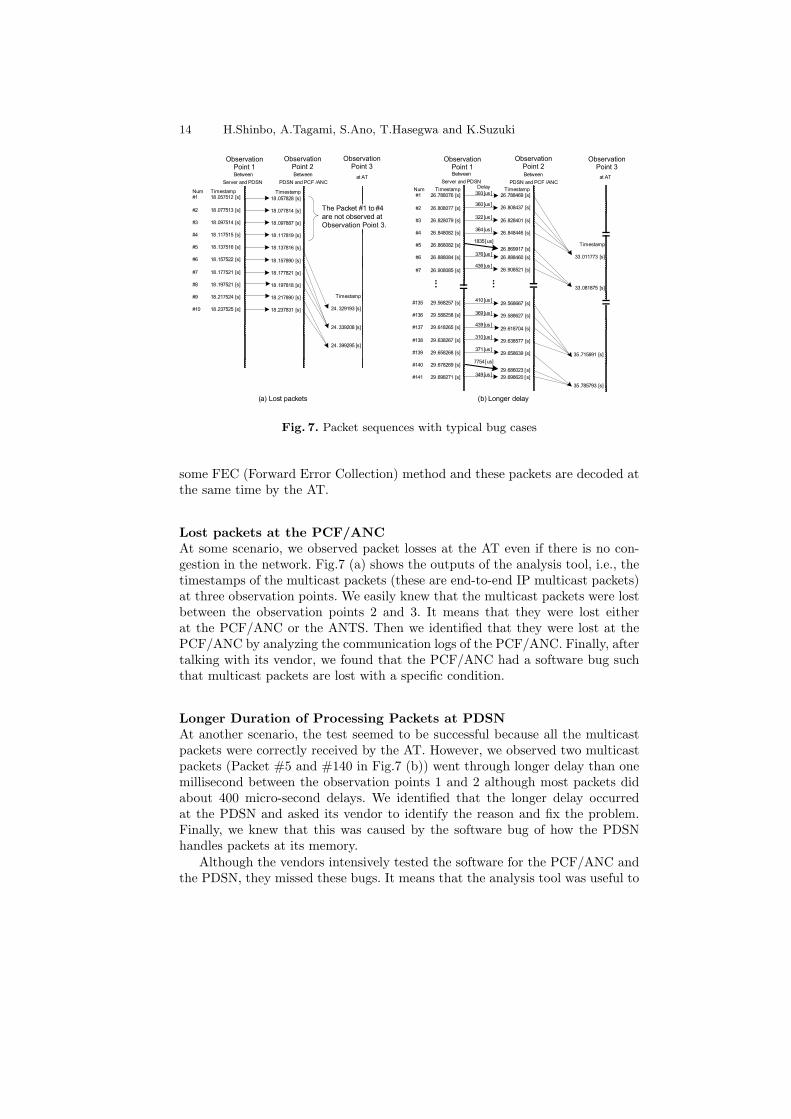
Fig. 7. Packet sequences with typical bug cases
some FEC (Forward Error Collection) method and these packets are decoded atthe same time by the AT.
Lost packets at the PCF/ANCAt some scenario, we observed packet losses at the AT even if there is no con-gestion in the network. Fig.7 (a) shows the outputs of the analysis tool, i.e., thetimestamps of the multicast packets (these are end-to-end IP multicast packets)at three observation points. We easily knew that the multicast packets were lostbetween the observation points 2 and 3. It means that they were lost eitherat the PCF/ANC or the ANTS. Then we identified that they were lost at thePCF/ANC by analyzing the communication logs of the PCF/ANC. Finally, aftertalking with its vendor, we found that the PCF/ANC had a software bug suchthat multicast packets are lost with a specific condition.
Longer Duration of Processing Packets at PDSNAt another scenario, the test seemed to be successful because all the multicastpackets were correctly received by the AT. However, we observed two multicastpackets (Packet #5 and #140 in Fig.7 (b)) went through longer delay than onemillisecond between the observation points 1 and 2 although most packets didabout 400 micro-second delays. We identified that the longer delay occurredat the PDSN and asked its vendor to identify the reason and fix the problem.Finally, we knew that this was caused by the software bug of how the PDSNhandles packets at its memory.
Although the vendors intensively tested the software for the PCF/ANC andthe PDSN, they missed these bugs. It means that the analysis tool was useful to

Practical End-to End Performance Testing Tool for 3G Networks 15
detect such bugs. Especially, in the case of Fig.7 (b), we would miss the softwarebug unless we used the analysis tool.
7 Related Work
As far as we know, there is no testing tool which captures packets or packet head-ers with synchronized timestamps at multiple observation points. Besides, therewould be no study for extracting IP headers from packets which are transferredon 3G mobile systems.
On the contrary, clock synchronization is studied for distributed systems.The most straight-forward way is to use the Global Positioning System [9]. Manyproducts are commercialized using the pps (plus per second) signal of GPS andsynchronize their clocks with an absolute precision of better than 10us to theabsolute time, i.e. UTC (Universal Time, Coordinated). However, the GPS re-quires a clear sky view, which is usually unavailable in our test-bed environments.There is another product, which synchronizes clocks with a precision of betterthan 1 nano-second using common timing signal [10] among nodes only whichare located within a few meters. This requirement is not fulfilled in our test-bedenvironment and this product requires a special and expensive hardware.
Over the years, many clock synchronization protocols, which would be imple-mented based on the software, have been designed for distributed system [11–16].NTP [11] and SNTP [12] are most prominent clock synchronization protocolsused in Internet; however, their several millisecond level precision is not enoughfor our testing tool. IEEE1588 [13] is a clock synchronization protocol over lo-cal area networks. Although this precision is one micro-second level on sometypes of local area networks, it is vulnerable to random delay on local areanetwork switches which would be used as the broadcast medium of our testingtool. Some clock synchronization protocol implementations [14, 15] achieve sev-eral micro-second precision. However, these optimize firmware of MAC (MediaAccess Control) protocol and require some hardware support.
Our clock synchronization scheme is similar to the clock synchronizationprotocol of [16] in that the both use the broadcast medium for compensat-ing non-deterministic packet delays. However, taking advantage of the fact thatclock synchronization needs to be maintained only for a testing duration, whichwould be just less than scores of minutes, we adopt a post-processing approachwhere the timestamps are synchronized after all IP packet headers are capturedwith timestamps. This makes our scheme far simple and efficient from the clocksynchronization protocol of [16].
8 Conclusion
This paper has proposed a multi-point packet header analysis tool for end-to-end performance tests for 3rd generation (3G) mobile systems. This tool extractsend-to-end IP packet headers with synchronized timestamps at multiple observa-tion points. The synchronized timestamps at multiple observation points enable
16 H.Shinbo, A.Tagami, S.Ano, T.Hasegwa and K.Suzuki
testers to identify a reason of performance degradation and to check whether eachnetwork node processes a packet within a predefined threshold. We implementedthis tool on off-the-shelf hardware platforms, i.e., lap-top personal computers,which enable this tool to be used widely for various purposes. The notable fea-tures of this tool are scores of micro-second precision in clock synchronizationwithout using any special hardware and a sophisticated end-to-end IP packetheader extraction algorithm without any drop. Due to these features, this toolis so practical and useful that it was used for testing a few commercial 3G mo-bile systems. Especially, scores of micro-second precision in synchronized clockswas useful to detect more than 10 bugs of some network nodes which were notdetected by their vendors. This was helpful to launch the commercial 3G ser-vices on time. Besides, although this tool is developed for testing 3G mobilesystems, the main functions of multi-point packet capture and scores of micro-second level clock synchronization are so general that this tool is used for testingvarious IP-based communication systems.
References
1. 3GPP2: cdma2000 High Rate Packet Data Air Interface Specification. 3GPP2 Spec.of C.S.0024-0 v4.0 (2002)
2. 3GPP2: Wireless IP Network Standard. 3GPP2 Spec. of X.S0011-001-C v1.0 (2003)3. ETS 300 406: Methods for Testing and Specification (MTS). Protocol and profile
conformance testing specifications Standardization methodology. (1995)4. IXIA, http://www.ixiacom.com/5. 3GPP2: cdma2000 High Rate Broadcast-Multicast Packet Data Air Interface Spec-
ification. 3GPP2 Spec. of C.S.0053-0 v2.0 (2005)6. Kyungtae K., Jinsung C. and Heonshik S.: Dynamic packet scheduling for cdma2000
1xEV-DO broadcast and multicast services. Proc. of Wireless Communications andNetworking Conference 2005 (WCNC2005), Vol4, pp 2393–2399. (2005)
7. tcpdump, http://www.tcpdump.org/8. tcpreplay, http://tcpreplay.synfin.net/9. Elliott D. Kaplan, editor: Understanding GPS: Principles and Applications. Artech
House. (1996)10. National Instruments Corporation PXI System, http://www.ni.com/pxi/.11. Mills D. L.: Internet Time Synchronization: Network Time Protocol. IEEE Trans.
Communications, 39(10), pp 1482-1493. (1991)12. Mills D. L.: Simple Network Time Protocol (SNTP) Version 4 for IPv4, IPv6 and
OSI. RFC 2030, IETF. (1996)13. IEEE1588: IEEE Standard for a Precision Clock Synchronization Protocol for Net-
worked Measurement and Control Systems. IEEE Standard 1588, 2002.14. Liao C., Martonosi M. and Clark W.: Experience with an adaptive globally-
synchronizing clock algorithm. Proc. of Eleventh Annual ACM Symposium on Par-allel Algorithms and Architectures (SPAA ’99), pp.106–114. (1999)
15. Maroti. M., Kusy B., Simon G. and Ledeczi A.: The Flooding TimeSynchronization Protocol. Proc. of the 2nd ACM Conference on Embedded Net-worked Sensor Systems (SenSys ’04), pp.39–49. (2004)
16. Elson J., Girod L. and Estrin D.: Fine-Grained Network Time Synchronizationusing Reference Broadcasts. Proc.of OSDI (Operating systems design and imple-mentation) ’02, pp.147–163. (2002)