Embed Size (px)
Citation preview
PRACTICAL GUIDE TO THE SAFE ERECTION OF
MULTI-ELEMENT STEEL STRUCTURES
Draft Edition August 2016
Australian Steel Institute in conjunction with
Brookfield Multiplex Constructions Pty Ltd
Practical Guide to the Safe Erection of Multi-Element Steel Structures | Preface
AUSTRALIAN STEEL INSTITUTE
(ABN) /ACN (94) 000 973 839
Practical Guide to the Safe Erection of Multi-Element Steel Structures
Copyright © 2016 by AUSTRALIAN STEEL INSTITUTE Published by: AUSTRALIAN STEEL INSTITUTE
All rights reserved. This guide or any part thereof must not be reproduced in any form without the written permission of Australian Steel Institute.
DRAFT EDITION AUGUST 2016
Australian Steel Institute Practical Guide to the Safe Erection of Multi-Element Steel Structures
Disclaimer: The information presented by the Australian Steel Institute in this publication has been prepared for general
information only and does not in any way constitute recommendations or professional advice. While every effort has been made and all reasonable care taken to ensure the accuracy of the information contained in this publication, this information should not be used or relied upon for any specific application without investigation and verification as to its accuracy, suitability and applicability by a competent professional person in this regard. The Australian Steel Institute, its officers and employees and the authors and editors of this publication do not give any warranties or make any representations in relation to the information provided herein and to the extent permitted by law (a) will not be held liable or responsible in any way; and (b) expressly disclaim any liability or responsibility for any loss or damage costs or expenses incurred in connection with this publication by any person, whether that person is the purchaser of this publication or not. Without limitation, this includes loss, damage, costs and expenses incurred as a result of the negligence of the authors, editors or publishers.
The information in this publication should not be relied upon as a substitute for independent due diligence, professional or legal advice and in this regards the services of a competent professional person or persons should be sought.
This document does not replace the need to review and manage obligations under the various state and national regulations applicable to building construction. Rather, this document may be used to establish a framework for process and controls that can help the stakeholder meet obligations to demonstrate duty of care on construction projects utilising structural steel.
This document does not mandate specific approaches to procedures and equipment to be used by the erector. It remains the erector’s responsibility to evaluate the total work environment and select an appropriate methodology, provided that at least equal levels of safety inherent in the processes outlined in this Guide are maintained.
PREFACE
This guidance document is one of the required deliverables resulting from an Enforceable Undertaking (EU) actioned by Brookfield Multiplex Constructions Pty Ltd. In order to provide a balanced view on industry good practice, the document was prepared by a working group including representatives from Australian Steel Institute and Brookfield Multiplex Constructions Pty Ltd and various industry representatives including engineers, fabricators and erectors.
It is intended the publication is used as a basis for industry awareness and education and to drive positive change, which forms a component of the Enforceable Undertaking.
The publication was peer reviewed by a range of subject matter experts and industry professionals prior to being published.
Indus
try R
eview
Draf
t
Practical Guide to the Safe Erection of Multi-Element Steel Structures | Table of Contents
Table of Contents
1. Introduction ................................................................................................................................... 1
1.1 Purpose .............................................................................................................................................................. 1 1.2 Scope .................................................................................................................................................................. 1 1.3 Terms and Definitions ......................................................................................................................................... 1 1.4 Stakeholders ....................................................................................................................................................... 2 1.5 Project Phases ................................................................................................................................................... 3 1.6 Opportunities to Influence Safety, Quality, Time and Cost ................................................................................ 4
2. Key Process Activities .................................................................................................................. 5
2.1 Communication and Consultation ...................................................................................................................... 5 2.2 Risk Planning Workshops................................................................................................................................... 6 2.3 Erection Sequence Methodology ....................................................................................................................... 7 2.4 Work Shift Pre-Start Meeting .............................................................................................................................. 7
Appendix A: Reference Material ........................................................................................................... 9
Appendix B: Example of an Erection Sequence Methodology ......................................................... 11
Indus
try R
eview
Draf
t

Practical Guide to the Safe Erection of Multi-Element Steel Structures | 1.1 Purpose 1
1. Introduction
1.1 Purpose
This Guide sets out practical guidance for the erection of multi-element steel structures. The purpose is to define the planning processes and controls necessary to help support best practice outcomes which mitigate health and safety risks for all stakeholders associated with the erection of multi-element steel structures.
Within the context of this document, “shall” indicates a statement is mandatory and “should” indicates a recommendation.
1.2 Scope
This Guide is intended for any person involved with the design, coordination, fabrication or erection of multi-element steel structures. The Guide is intended to apply to all types of projects and provides a framework for the user to determine what steps are appropriate for their particular scope of work.
1.3 Terms and Definitions
TERM DEFINITION
Competent Person: A person who has acquired through education, training, qualification or experience (of a combination of same) the knowledge and skill that enable that person to perform the required task correctly and safely.
Erection Drawings: Drawings that are included in the Erection Sequence Methodology which depict information essential to the safe erection of the multi-element steel structure. These may include Erection Sequence Diagrams.
Erection Sequence Diagrams: Diagram/s which depict any required sequencing in the erection of members. These should include location and sequence of installation and removal, of any temporary propping or bracing.
Erection Engineer: The engineer responsible for the temporary condition and stability aspects of a multi-element steel structure during erection. This role requires the person to have a sound knowledge of the structure and its capacity in a temporary state.
Erection Sequence Methodology (ESM): The documented process for the safe erection of a multi-element steel structure. The ESM should include an element by element sequence for installation for all steel members and be supported with Erection Drawings.
Principal Contractor: The person or organisation engaged by the client to execute the contract works and authorised to have management or control of the workplace.
Safe Work Method Statement (SWMS): A document that sets out the high risk construction work activities to be carried out at a workplace, the hazards arising from these activities and the measures to be put in place to control the risks involved.
Structural Design Engineer: The engineer or engineering organisation, with experience in structural steel, responsible for the engineering design of the overall building and for defining the technical data and requirements for the multi-element steel structure.
Indus
try R
eview
Draf
t
Practical Guide to the Safe Erection of Multi-Element Steel Structures | 1.4 Stakeholders 2
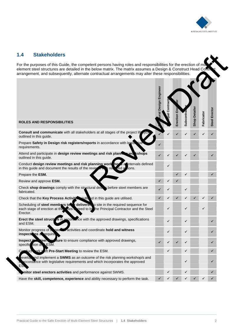
1.4 Stakeholders
For the purposes of this Guide, the competent persons having roles and responsibilities for the erection of multi-element steel structures are detailed in the below matrix. The matrix assumes a Design & Construct Head Contract arrangement, and subsequently, alternate contractual arrangements may alter these responsibilities.
ROLES AND RESPONSIBILITIES S
tru
ctu
ral D
esig
n E
ng
ine
er
Pri
ncip
al C
on
tracto
r
Ere
cti
on
En
gin
eer
Su
bc
on
tracto
r
Sh
op
Deta
iler
Fa
bri
cato
r
Ste
el E
recto
r
Consult and communicate with all stakeholders at all stages of the project lifecycle
outlined in this guide.
Prepare Safety in Design risk registers/reports in accordance with legislative
requirements.
Attend and participate in design review meetings and risk planning workshops
outlined in this guide.
Conduct design review meetings and risk planning workshops at intervals defined
in this guide and document the results of the reviews with required actions.
Prepare the ESM.
Review and approve ESM.
Check shop drawings comply with the structural design before steel members are
fabricated.
Check that the Key Process Activities outlined in this guide are utilised.
Scheduling of steel members to be delivered to site in the required sequence for
each stage of erection at the times agreed to by the Principal Contractor and the Steel Erector.
Erect the steel structure in accordance with the approved drawings, specifications
and ESM.
Monitor progress of inspection activities and coordinate hold and witness inspections as required.
Inspect the steel structure to ensure compliance with approved drawings,
specification and ESM.
Conduct work shift Pre-Start Meeting to review the ESM.
Develop and implement a SWMS as an outcome of the risk planning workshop/s and
in accordance with legislative requirements and which incorporates the approved ESM.
Monitor steel erectors activities and performance against SWMS.
Have the skill, competence, experience and ability necessary to perform the task.
Indus
try R
eview
Draf
t
Practical Guide to the Safe Erection of Multi-Element Steel Structures | 1.5 Project Phases 3
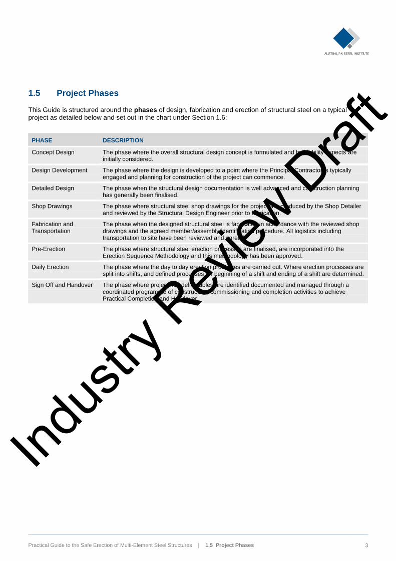
1.5 Project Phases
This Guide is structured around the phases of design, fabrication and erection of structural steel on a typical project as detailed below and set out in the chart under Section 1.6:
PHASE DESCRIPTION
Concept Design The phase where the overall structural design concept is formulated and buildability aspects are initially considered.
Design Development The phase where the design is developed to a point where the Principal Contractor is typically engaged and planning for construction of the project can commence.
Detailed Design The phase when the structural design documentation is well advanced and construction planning has generally been finalised.
Shop Drawings The phase where structural steel shop drawings for the project are produced by the Shop Detailer and reviewed by the Structural Design Engineer prior to fabrication.
Fabrication and Transportation
The phase when the designed structural steel is fabricated in accordance with the reviewed shop drawings and the agreed member/assembly identification procedure. All logistics including transportation to site have been reviewed and agreed.
Pre-Erection The phase where structural steel erection processes are finalised, are incorporated into the Erection Sequence Methodology and this methodology has been approved.
Daily Erection The phase where the day to day erection processes are carried out. Where erection processes are split into shifts, and defined processes for beginning of a shift and ending of a shift are determined.
Sign Off and Handover The phase where project key deliverables are identified documented and managed through a coordinated programme of construction, commissioning and completion activities to achieve Practical Completion and Handover.
Indus
try R
eview
Draf
t
Practical Guide to the Safe Erection of Multi-Element Steel Structures | 1.6 Opportunities to Influence Safety, Quality, Time and Cost 4
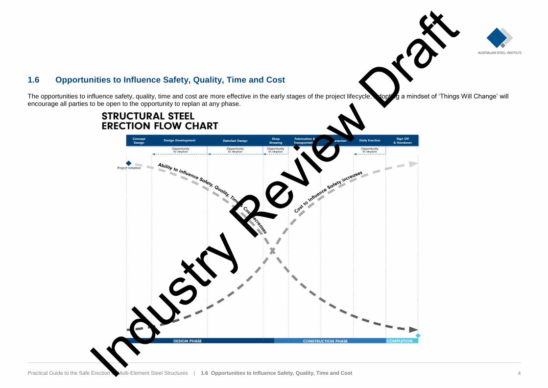
1.6 Opportunities to Influence Safety, Quality, Time and Cost
The opportunities to influence safety, quality, time and cost are more effective in the early stages of the project lifecycle. Adopting a mindset of ‘Things Will Change’ will encourage all parties to be open to the opportunity to replan at any phase.
Indus
try R
eview
Draf
t
Practical Guide to the Safe Erection of Multi-Element Steel Structures | 2. Key Process Activities 5
2. Key Process Activities
The key process activities used to coordinate the management and control in respect of maximising safe work outcomes of the erection of multi-element steel structures include:
» Communication and consultation
» Risk planning workshops
» Erection sequence methodology
» Work shift pre-start meeting
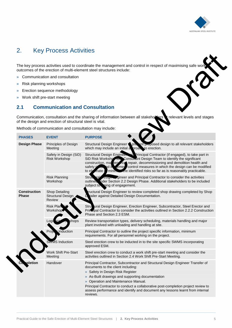
2.1 Communication and Consultation
Communication, consultation and the sharing of information between all stakeholders at relevant levels and stages of the design and erection of structural steel is vital.
Methods of communication and consultation may include:
PHASES EVENT PURPOSE
Design Phase Principles of Design Meeting
Structural Design Engineer to present proposed design to all relevant stakeholders which may include an initial approach to erection.
Safety in Design (SiD) Risk Workshop
Structural Design Engineer and Principal Contractor (if engaged), to take part in SiD Risk Workshop with Consultant Design Team to identify the significant construction, maintenance, repair, decommissioning and demolition health and safety risks and implement control measures in which the design can be modified to eliminate or minimise the identified risks so far as is reasonably practicable.
Risk Planning Workshop
Structural Design Engineer and Principal Contractor to consider the activities outlined under Section 2.2 Design Phase. Additional stakeholders to be included subject to timing of engagement.
Construction Phase
Shop Detailing Structural Design Review
Structural Design Engineer to review completed shop drawing completed by Shop Detailer against Detailed Design Documentation.
Risk Planning Workshop
Structural Design Engineer, Erection Engineer, Subcontractor, Steel Erector and Principal Contractor to consider the activities outlined in Section 2.2.2 Construction Phase and Section 2.3 ESM.
Logistics Workshops Review transportation types, delivery scheduling, materials handling and major plant involved with unloading and handling at site.
Project Induction Principal Contractor to outline the project specific information, minimum requirements. For all personnel working on the project.
SWMS Induction Steel erection crew to be inducted in to the site specific SWMS incorporating approved ESM.
Work Shift Pre-Start Meeting
Steel erection crew to conduct a work shift pre-start meeting and consider the activities outlined in Section 2.4 Work Shift Pre-Start Meeting.
Completion Handover Principal Contractor, Subcontractor and Structural Design Engineer Transfer of documents to the client including:
» Safety in Design Risk Register
» As-Built drawings and supporting documentation
» Operation and Maintenance Manual.
Principal Contractor to conduct a collaborative post-completion project review to assess performance and identify and document any lessons learnt from internal reviews.
Indus
try R
eview
Draf
t
Practical Guide to the Safe Erection of Multi-Element Steel Structures | 2. Key Process Activities 6
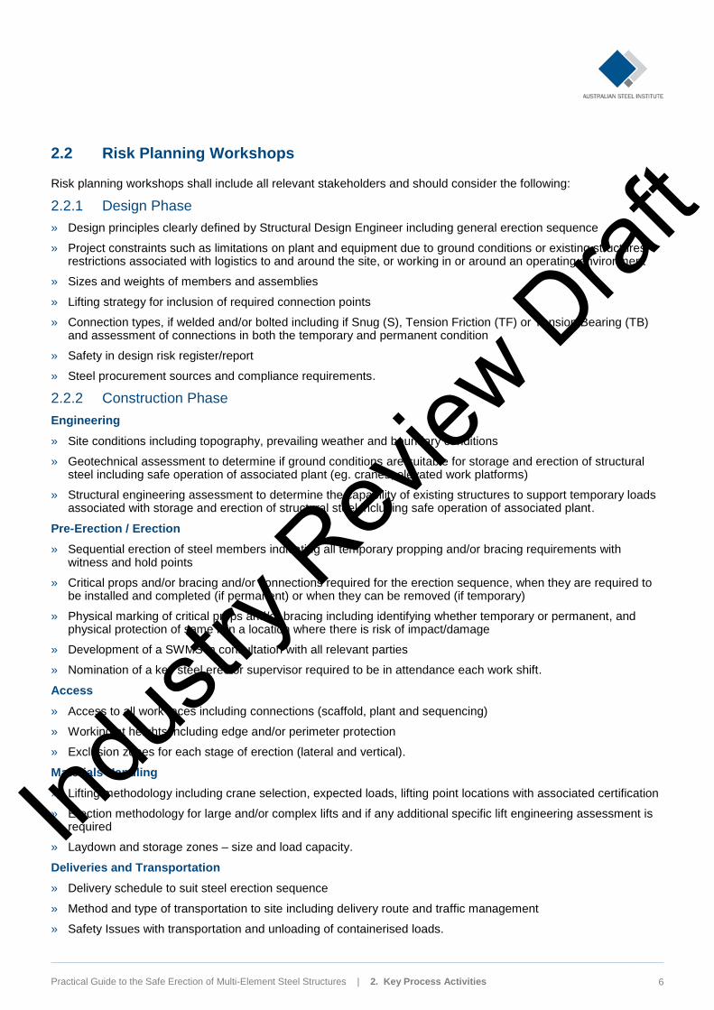
2.2 Risk Planning Workshops
Risk planning workshops shall include all relevant stakeholders and should consider the following:
2.2.1 Design Phase
» Design principles clearly defined by Structural Design Engineer including general erection sequence
» Project constraints such as limitations on plant and equipment due to ground conditions or existing structures, restrictions associated with logistics to and around the site, or working in or around an operating environment
» Sizes and weights of members and assemblies
» Lifting strategy for inclusion of required connection points
» Connection types, if welded and/or bolted including if Snug (S), Tension Friction (TF) or Tension Bearing (TB) and assessment of connections in both the temporary and permanent condition
» Safety in design risk register/report
» Steel procurement sources and compliance requirements.
2.2.2 Construction Phase
Engineering
» Site conditions including topography, prevailing weather and boundary conditions
» Geotechnical assessment to determine if ground conditions are suitable for storage and erection of structural steel including safe operation of associated plant (eg. cranes, elevated work platforms)
» Structural engineering assessment to determine the capability of existing structures to support temporary loads associated with storage and erection of structural steel including safe operation of associated plant.
Pre-Erection / Erection
» Sequential erection of steel members indicating all temporary propping and/or bracing requirements with witness and hold points
» Critical props and/or bracing and/or connections required for the erection sequence, when they are required to be installed and completed (if permanent) or when they can be removed (if temporary)
» Physical marking of critical props and/or bracing including identifying whether temporary or permanent, and physical protection of same if in a location where there is risk of impact/damage
» Development of a SWMS in consultation with all relevant parties
» Nomination of a key steel erector supervisor required to be in attendance each work shift.
Access
» Access to all work faces including connections (scaffold, plant and sequencing)
» Working at heights including edge and/or perimeter protection
» Exclusion zones for each stage of erection (lateral and vertical).
Materials Handling
» Lifting methodology including crane selection, expected loads, lifting point locations with associated certification
» Erection methodology for large and/or complex lifts and if any additional specific lift engineering assessment is required
» Laydown and storage zones – size and load capacity.
Deliveries and Transportation
» Delivery schedule to suit steel erection sequence
» Method and type of transportation to site including delivery route and traffic management
» Safety Issues with transportation and unloading of containerised loads.
Indus
try R
eview
Draf
t
Practical Guide to the Safe Erection of Multi-Element Steel Structures | 2. Key Process Activities 7
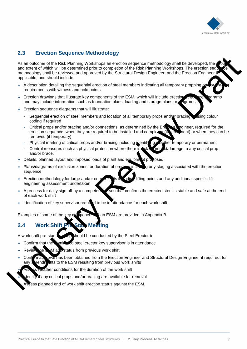
2.3 Erection Sequence Methodology
As an outcome of the Risk Planning Workshops an erection sequence methodology shall be developed, the scope and extent of which will be determined prior to completion of the Risk Planning Workshops. The erection sequence methodology shall be reviewed and approved by the Structural Design Engineer, and the Erection Engineer if applicable, and should include:
» A description detailing the sequential erection of steel members indicating all temporary propping and/or bracing requirements with witness and hold points
» Erection drawings that illustrate key components of the ESM, which will include erection sequence diagrams and may include information such as foundation plans, loading and storage plans or diagrams
» Erection sequence diagrams that will illustrate:
- Sequential erection of steel members and location of all temporary props and/or bracing utilising colour coding if required
- Critical props and/or bracing and/or connections, as determined by the Erection Engineer, required for the erection sequence, when they are required to be installed and completed (if permanent) or when they can be removed (if temporary)
- Physical marking of critical props and/or bracing including identifying whether temporary or permanent
- Control measures such as physical protection where there is risk of impact/damage to any critical prop and/or brace.
» Details, planned layout and imposed loads of plant and equipment proposed
» Plans/diagrams of exclusion zones for duration of erection including any staging associated with the erection sequence
» Erection methodology for large and/or complex lifts including lifting points and any additional specific lift engineering assessment undertaken
» A process for daily sign off by a competent person that confirms the erected steel is stable and safe at the end of each work shift
» Identification of key supervisor required to be in attendance for each work shift.
Examples of some of the key components of an ESM are provided in Appendix B.
2.4 Work Shift Pre-Start Meeting
A work shift pre-start meeting should be conducted by the Steel Erector to:
» Confirm that the nominated steel erector key supervisor is in attendance
» Review the ESM and status from previous work shift
» Confirm approval has been obtained from the Erection Engineer and Structural Design Engineer if required, for any amendments to the ESM resulting from previous work shifts
» Assess weather conditions for the duration of the work shift
» Identify if any critical props and/or bracing are available for removal
» Assess planned end of work shift erection status against the ESM. Indus
try R
eview
Draf
t

APPENDIX A Reference Material Ind
ustry
Rev
iew D
raft
Practical Guide to the Safe Erection of Multi-Element Steel Structures | Appendix A: Reference Materials 9
Appendix A: Reference Material
A.1 General References
1. Australian Steel Institute, ‘Structural steelwork fabrication and erection code of practice’, 2014.
2. Standards Australia/Standards New Zealand, AS 4100:1998 (R2016) Steel Structures
3. Standards Australia/Standards New Zealand, DR AS/NZS 5131:2016 Structural steelwork – Fabrication and erection.
A.2 Workplace Health and Safety
1. Safe Work Australia, ‘Construction work. Code of practice’, 2013.
2. Safe Work Australia, ‘Construction work – roof work. Information sheet’, 2016.
3. Safe Work Australia, ‘Construction work – steel erection. Information sheet’, 2016.
4. Safe Work Australia, ‘Hazardous manual tasks. Code of practice’, 2011.
5. Safe Work Australia, ‘How to manage work health and safety risks. Code of practice’, 2011.
6. Safe Work Australia, ‘Managing the risk of falls at workplaces. Code of practice’, 2015.
7. Safe Work Australia, ‘Safe design of structures. Code of practice’, 2012.
8. Safe Work Australia, ‘Managing the risk of falls at workplaces code of practice’, 2015.
9. Safe Work Australia, ‘Safe Work Method Statement for High Risk Construction. Information Sheet’, 2014.
10. Safe Work SA, ‘Fact sheet. Working at heights in construction’, n.d.
11. Western Australia Commission for Occupational Safety and Health, ‘Code of practice. Safe design of buildings and structures’, 2009.
12. WorkCover New South Wales, ‘Safe design of structures code of practice’, 2014.
13. WorkCover New South Wales, ‘Dogging’, 2013
14. Workplace Health and Safety Queensland, ‘A guide for doggers’, 2010.
15. Workplace Health and Safety Queensland, ‘Steel construction code of practice’, 2004 rev. 2011.
16. WorkSafe Victoria, ‘Designing safer buildings and structures’, 2005.
17. WorkSafe Victoria, ‘Safety erection of structural steel for buildings. Industry standard’, edition no. 1, 2009.
Indus
try R
eview
Draf
t

APPENDIX B Example of an Erection Sequence Methodology Indus
try R
eview
Draf
t
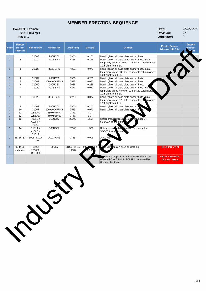
Contract: Example Date: XX/XX/XXXX
Site: Building 1 Revision: XX
Phase: 1 Originator: X
Stage
Member
Erection
Sequence
Member Mark Member Size Length (mm) Mass (kg) CommentErection Engineer
Witness / Hold Point
Erection
Engineer
Sign Off
1 1 C1003 200UC60 3966 0.256 Hand tighten all base plate anchor bolts.
1 2 C1014 89X6 SHS 4325 0.146 Hand tighten all base plate anchor bolts. Install
temporary props P1 + P2, connect to column above
1/2 height from FSL
1 3 C1027 89X6 SHS 4325 0.073 Hand tighten all base plate anchor bolts. Install
temporary props P3 + P4, connect to column above
1/2 height from FSL
1 4 C1003 200UC60 3966 0.256 Hand tighten all base plate anchor bolts.
1 5 C1007 150x100x5RHS 3598 0.076 Hand tighten all base plate anchor bolts.
1 6 C1002 200UC60 3966 0.256 Hand tighten all base plate anchor bolts.
1 7 C1029 89X6 SHS 4271 0.072 Hand tighten all base plate anchor bolts. Install
temporary props P5 + P6, connect to column above
1/2 height from FSL
1 8 C1028 89X6 SHS 4270 0.072 Hand tighten all base plate anchor bolts. Install
temporary props P7 + P8, connect to column above
1/2 height from FSL
1 9 C1002 200UC60 3966 0.256 Hand tighten all base plate anchor bolts.
1 10 C1007 150x100x5RHS 3598 0.076 Hand tighten all base plate anchor bolts.
1 11 WB1002 250X90PFC 7741 0.27
1 12 WB1002 250X90PFC 7741 0.27
1 13 R1010 +
A1004 +
R1016
310UB40 23100 1.56T Rafter preassembled, includes member 2 x
50x50EA at end columns
1 14 R1011 +
A1005 +
R1017
360UB57 23100 1.56T Rafter preassembled, includes member 2 x
50x50EA at end columns
1 15, 16, 17 T1005, T1005,
T1006
100X4SHS 7758 0.096 Any order
1 18 to 25
inclusive
RB1001,
RB1002,
RB1003
20DIA 11059, 8119,
11084
0.029, 0.022,
0.0.29
Any order, tension once all installed HOLD POINT #1
1 Temporary props P1 to P8 inclusive able to be
removed ONCE HOLD POINT #1 released by
Erection Engineer
PROP REMOVAL
ACCEPTANCE
MEMBER ERECTION SEQUENCE
1 of 3
Indus
try R
eview
Draf
t
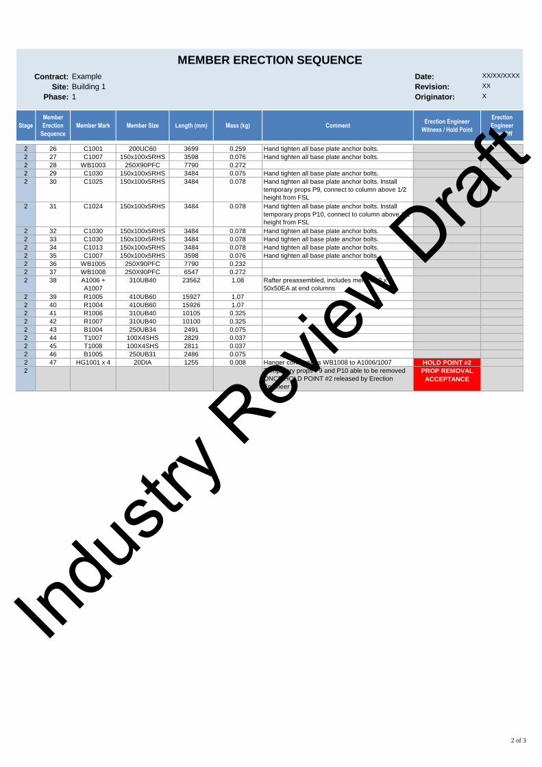
Contract: Example Date: XX/XX/XXXX
Site: Building 1 Revision: XX
Phase: 1 Originator: X
Stage
Member
Erection
Sequence
Member Mark Member Size Length (mm) Mass (kg) CommentErection Engineer
Witness / Hold Point
Erection
Engineer
Sign Off
MEMBER ERECTION SEQUENCE
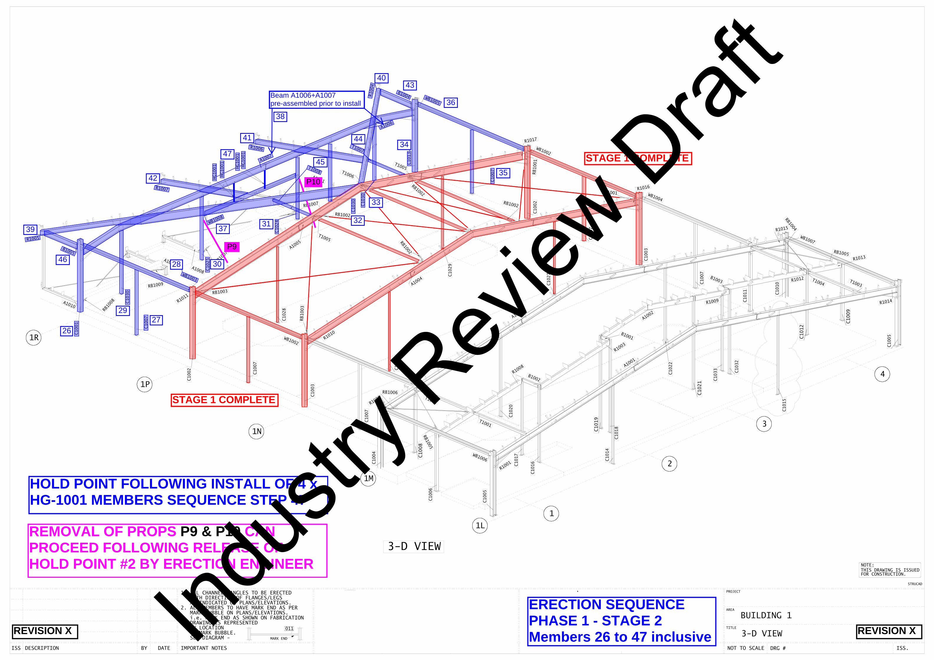
2 26 C1001 200UC60 3699 0.259 Hand tighten all base plate anchor bolts.
2 27 C1007 150x100x5RHS 3598 0.076 Hand tighten all base plate anchor bolts.
2 28 WB1003 250X90PFC 7790 0.272
2 29 C1030 150x100x5RHS 3484 0.075 Hand tighten all base plate anchor bolts.
2 30 C1025 150x100x5RHS 3484 0.078 Hand tighten all base plate anchor bolts. Install
temporary props P9, connect to column above 1/2
height from FSL
2 31 C1024 150x100x5RHS 3484 0.078 Hand tighten all base plate anchor bolts. Install
temporary props P10, connect to column above 1/2
height from FSL
2 32 C1030 150x100x5RHS 3484 0.078 Hand tighten all base plate anchor bolts.
2 33 C1030 150x100x5RHS 3484 0.078 Hand tighten all base plate anchor bolts.
2 34 C1013 150x100x5RHS 3484 0.078 Hand tighten all base plate anchor bolts.
2 35 C1007 150x100x5RHS 3598 0.076 Hand tighten all base plate anchor bolts.
2 36 WB1005 250X90PFC 7790 0.232
2 37 WB1008 250X90PFC 6547 0.272
2 38 A1006 +
A1007
310UB40 23562 1.08 Rafter preassembled, includes member 2 x
50x50EA at end columns
2 39 R1005 410UB60 15927 1.07
2 40 R1004 410UB60 15926 1.07
2 41 R1006 310UB40 10105 0.325
2 42 R1007 310UB40 10100 0.325
2 43 B1004 250UB34 2491 0.075
2 44 T1007 100X4SHS 2829 0.037
2 45 T1008 100X4SHS 2811 0.037
2 46 B1005 250UB31 2486 0.075
2 47 HG1001 x 4 20DIA 1255 0.008 Hanger connections WB1008 to A1006/1007 HOLD POINT #2
2 Temporary props P9 and P10 able to be removed
ONCE HOLD POINT #2 released by Erection
Engineer
PROP REMOVAL
ACCEPTANCE
2 of 3
Indus
try R
eview
Draf
t
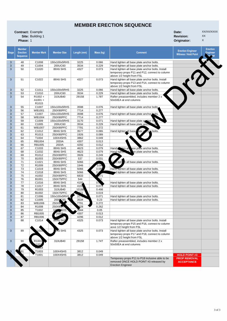
Contract: Example Date: XX/XX/XXXX
Site: Building 1 Revision: XX
Phase: 1 Originator: X
Stage
Member
Erection
Sequence
Member Mark Member Size Length (mm) Mass (kg) CommentErection Engineer
Witness / Hold Point
Erection
Engineer
Sign Off
MEMBER ERECTION SEQUENCE
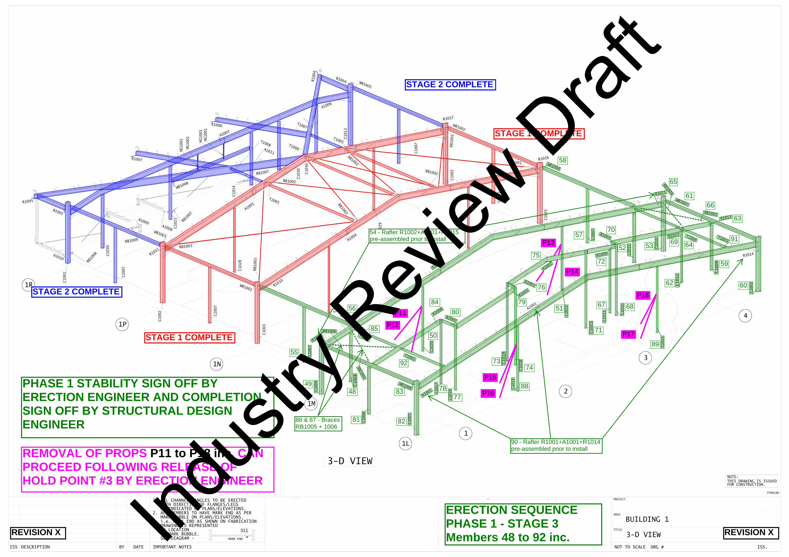
3 48 C1008 150x100x5RHS 3225 0.066 Hand tighten all base plate anchor bolts.
3 49 C1004 200UC60 3534 0.229 Hand tighten all base plate anchor bolts.
3 50 C1020 89X6 SHS 4327 0.073 Hand tighten all base plate anchor bolts. Install
temporary props P11 and P12, connect to column
above 1/2 height from FSL
3 51 C1022 89X6 SHS 4327 0.073 Hand tighten all base plate anchor bolts. Install
temporary props P13 and P14, connect to column
above 1/2 height from FSL
3 52 C1011 150x100x5RHS 3225 0.066 Hand tighten all base plate anchor bolts.
3 53 C1010 200UC60 3534 0.229 Hand tighten all base plate anchor bolts.
3 54 R1002 +
A1001 +
R1015
310UB40 29158 1.78T Rafter preassembled, includes member 2 x
50x50EA at end columns
3 55 C1007 150x100x5RHS 3598 0.076 Hand tighten all base plate anchor bolts.
3 56 WB1001 250X90PFC 7714 0.277
3 57 C1007 150x100x5RHS 3598 0.076 Hand tighten all base plate anchor bolts.
3 58 WB1004 250X90PFC 7714 0.277
3 59 C1009 150x100x5RHS 3170 0.071 Hand tighten all base plate anchor bolts.
3 60 C1005 200UC60 3534 0.229 Hand tighten all base plate anchor bolts.
3 61 WB1007 250X90PFC 7791 0.272
3 62 C1012 89X6 SHS 3577 0.065 Hand tighten all base plate anchor bolts.
3 63 R1013 250X90PFC 1926 0.089
3 64 T1004 100X4SHS 3862 0.049
3 65 RB1004 20DIA 4307 0.013
3 66 RB1005 20DIA 4292 0.012
3 67 C1033 89X6 SHS 4623 0.079 Hand tighten all base plate anchor bolts.
3 68 C1032 89X6 SHS 4623 0.079 Hand tighten all base plate anchor bolts.
3 69 R1012 250X90PFC 3926 0.249
3 70 B1003 250X90PFC 537 0.031
3 71 C1021 89X6 SHS 5066 0.089 Hand tighten all base plate anchor bolts.
3 72 R1009 250X90PFC 1946 0.94
3 73 C1019 89X6 SHS 5066 0.089 Hand tighten all base plate anchor bolts.
3 74 C1018 89X6 SHS 5066 0.089 Hand tighten all base plate anchor bolts.
3 75 A1002 250X90PFC 6833 0.271
3 76 B1001 150X75PFC 544 0.01
3 77 C1016 89X6 SHS 4193 0.073 Hand tighten all base plate anchor bolts.
3 78 C1017 89X6 SHS 4193 0.073 Hand tighten all base plate anchor bolts.
3 79 R1003 310UB40 10188 0.498
3 80 B1002 150X75PFC 1071 0.019
3 81 C1006 150x100x5RHS 3170 0.071 Hand tighten all base plate anchor bolts.
3 82 C1005 200UC60 3534 0.23 Hand tighten all base plate anchor bolts.
3 83 WB1006 250X90PFC 7791 0.272
3 84 R1008 250X90PFC 5928 0.262
3 85 T1002 100X4SHS 3944 0.05
3 86 RB1005 20DIA 4307 0.013
3 87 RB1006 20DIA 4296 0.012
3 88 C1014 89X6 SHS 4325 0.073 Hand tighten all base plate anchor bolts. Install
temporary props P15 and P16, connect to column
aove 1/2 height from FSL
3 89 C1015 89X6 SHS 4325 0.073 Hand tighten all base plate anchor bolts. Install
temporary props P17 and P18, connect to column
above 1/2 height from FSL
3 90 R1001 +
A1001 +
R1014
310UB40 29158 1.74T Rafter preassembled, includes member 2 x
50x50EA at end columns
3 91 T1003 100X4SHS 3812 0.049
3 92 T1001 100X4SHS 3812 0.049 HOLD POINT #3
3 Temporary props P11 to P18 inclusive able to be
removed ONCE HOLD POINT #3 released by
Erection Engineer
PROP REMOVAL
ACCEPTANCE
3 of 3
Indus
try R
eview
Draf
t
1L
1M
1N
1P
3
1R
1
2
4
C1001
C1002
C1006
C1007
C1008
C1007
C1005
C1009
C1010
C1011
C1012
C1007
C1003
C1007
C1002
C1015
C1018C1019
C1020
C1021
C1022
C1014
C1025
C1027
C1028
C1029
C1030
C1030
C1032
C1033
R1017
R1011
R1016
R1015
R1002
R1001
B1001
T1002
WB1003 T1004
WB1004
WB1002
T1005
T1005
R1004
T1007
A1006
R1006
R1007
RB1002
RB1002
RB1002
RB1003
RB1005
A1005
A1004
A1001
A1001
A1010
A1009A1008
A1011
R1013RB1007
RB1008
RB1009
RB1007
C1007
C1030
A1007
WB1008
HG1001
HG1001
HG1001
HG1001
C1005
C1004
WB1007
RB1004
R1012B1003
R1009
A1002
R1003
B1002
R1008
T1001
WB1001
RB1006
C1003
R1010
RB1003
R1005
B1005
WB1002
T1008
C1024
T1006
RB1002
C1013
B1004
RB1001
RB1001
R1014
C1007
WB1005
RB1005
WB1006
C1017
C1016
C1014
T1003
1. ALL CHANNELS/ANGLES TO BE ERECTED WITH DIRECTION OF FLANGES/LEGS AS INDICATED ON PLANS/ELEVATIONS.
MARK BUBBLE ON PLANS/ELEVATIONS. i.e. MARK END AS SHOWN ON FABRICATION
OF MARK BUBBLE. BY LOCATION DRAWING IS REPRESENTED
SEE DIAGRAM -
2. ALL MEMBERS TO HAVE MARK END AS PER
DESCRIPTIONISS BY DATE IMPORTANT NOTES DRN. DATE. CHK. JOB # NOT TO SCALE DRG #
TITLE
AREA
PROJECT
MARK END
011
STRUCTURAL STEEL DETAILINGAND 3D MODELLING
www.innovatuz.com.auEmail: [email protected]
JG
3-D VIEW
Tel: (07) 5588 5155
CLIENT JOB # 11064 11064-
BYRON CENTRAL HOSPITAL
YB
YB
BUILDING 1
BE11064 DV-1004
TAMWORTH NSW 2340
47 SHOWGROUND RD
P : 02 6765 9311
F : 02 6765 3926
FOR CONSTRUCTION.
STRUCAD
NOTE:THIS DRAWING IS ISSUED
27/02/15
27/02/15 ISS. 2
3-D VIEW
4
2
3
1
10
6
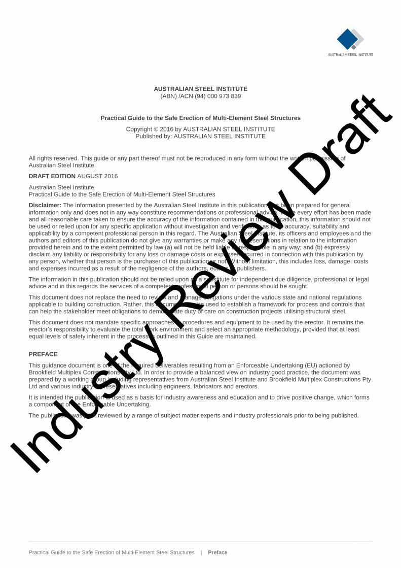
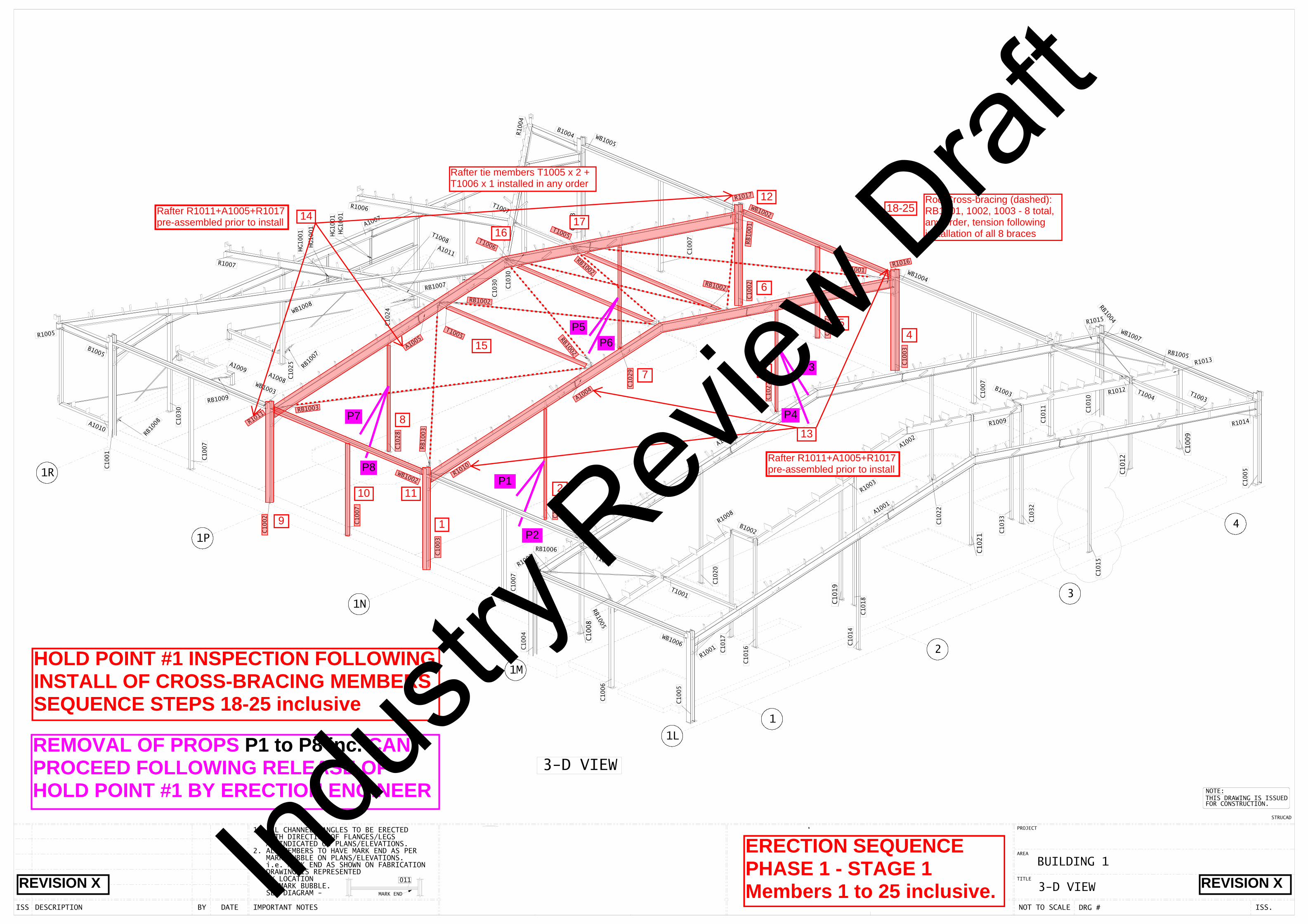
ERECTION SEQUENCEPHASE 1 - STAGE 1Members 1 to 25 inclusive.
7
8
9
5
11
12
13
1418-25
Rod Cross-bracing (dashed): RB1001, 1002, 1003 - 8 total,any order, tension followinginstallation of all 8 braces
15
1617
Rafter R1011+A1005+R1017pre-assembled prior to install
Rafter R1011+A1005+R1017pre-assembled prior to install
REVISION X REVISION X
Rafter tie members T1005 x 2 +T1006 x 1 installed in any order
HOLD POINT #1 INSPECTION FOLLOWINGINSTALL OF CROSS-BRACING MEMBERSSEQUENCE STEPS 18-25 inclusive
P1
P2
P3
P4
P5P6
P7
P8
REMOVAL OF PROPS P1 to P8 inc. CANPROCEED FOLLOWING RELEASE OFHOLD POINT #1 BY ERECTION ENGINEER
Indus
try R
eview
Draf
t
1L
1M
1N
1P
3
1R
1
2
4
C1001
C1002
C1006
C1007
C1008
C1007
C1005
C1009
C1010
C1011
C1012
C1007
C1003
C1007
C1002
C1015
C1018C1019
C1020
C1021
C1022
C1014
C1025
C1027
C1028
C1029
C1030
C1030
C1032
C1033
R1017
R1011
R1016
R1015
R1002
R1001
B1001
T1002
WB1003 T1004
WB1004
WB1002
T1005
T1005
R1004
T1007
A1006
R1006
R1007
RB1002
RB1002
RB1002
RB1003
RB1005
A1005
A1004
A1001
A1001
A1010
A1009A1008
A1011
R1013RB1007
RB1008
RB1009
RB1007
C1007
C1030
A1007
WB1008
HG1001
HG1001
HG1001
HG1001
C1005
C1004
WB1007
RB1004
R1012B1003
R1009
A1002
R1003
B1002
R1008
T1001
WB1001
RB1006
C1003
R1010
RB1003
R1005
B1005
WB1002
T1008
C1024
T1006
RB1002
C1013
B1004
RB1001
RB1001
R1014
C1007
WB1005
RB1005
WB1006
C1017
C1016
C1014
T1003
1. ALL CHANNELS/ANGLES TO BE ERECTED WITH DIRECTION OF FLANGES/LEGS AS INDICATED ON PLANS/ELEVATIONS.
MARK BUBBLE ON PLANS/ELEVATIONS. i.e. MARK END AS SHOWN ON FABRICATION
OF MARK BUBBLE. BY LOCATION DRAWING IS REPRESENTED
SEE DIAGRAM -
2. ALL MEMBERS TO HAVE MARK END AS PER
DESCRIPTIONISS BY DATE IMPORTANT NOTES DRN. DATE. CHK. JOB # NOT TO SCALE DRG #
TITLE
AREA
PROJECT
MARK END
011
STRUCTURAL STEEL DETAILINGAND 3D MODELLING
www.innovatuz.com.auEmail: [email protected]
JG
3-D VIEW
Tel: (07) 5588 5155
CLIENT JOB # 11064 11064-
BYRON CENTRAL HOSPITAL
YB
YB
BUILDING 1
BE11064 DV-1004
TAMWORTH NSW 2340
47 SHOWGROUND RD
P : 02 6765 9311
F : 02 6765 3926
FOR CONSTRUCTION.
STRUCAD
NOTE:THIS DRAWING IS ISSUED
27/02/15
27/02/15 ISS. 2
3-D VIEW
26
ERECTION SEQUENCEPHASE 1 - STAGE 2Members 26 to 47 inclusiveREVISION X REVISION X
STAGE 1 COMPLETE
STAGE 1 COMPLETE
27
28
36
35
34
33
31 32
30
29
37
Beam A1006+A1007pre-assembled prior to install
38
39
40
41
42
43
44
45
46
47
HOLD POINT FOLLOWING INSTALL OF 4 xHG-1001 MEMBERS SEQUENCE STEP 47
REMOVAL OF PROPS P9 & P10 CANPROCEED FOLLOWING RELEASE OFHOLD POINT #2 BY ERECTION ENGINEER
P9
P10
Indus
try R
eview
Draf
t
1L
1M
1N
1P
3
1R
1
2
4
C1001
C1002
C1006
C1007
C1008
C1007
C1005
C1009
C1010
C1011
C1012
C1007
C1003
C1007
C1002
C1015
C1018C1019
C1020
C1021
C1022
C1014
C1025
C1027
C1028
C1029
C1030
C1030
C1032
C1033
R1017
R1011
R1016
R1015
R1002
R1001
B1001
T1002
WB1003 T1004
WB1004
WB1002
T1005
T1005
R1004
T1007
A1006
R1006
R1007
RB1002
RB1002
RB1002
RB1003
RB1005
A1005
A1004
A1001
A1001
A1010
A1009A1008
A1011
R1013RB1007
RB1008
RB1009
RB1007
C1007
C1030
A1007
WB1008
HG1001
HG1001
HG1001
HG1001
C1005
C1004
WB1007
RB1004
R1012B1003
R1009
A1002
R1003
B1002
R1008
T1001
WB1001
RB1006
C1003
R1010
RB1003
R1005
B1005
WB1002
T1008
C1024
T1006
RB1002
C1013
B1004
RB1001
RB1001
R1014
C1007
WB1005
RB1005
WB1006
C1017
C1016
C1014
T1003
1. ALL CHANNELS/ANGLES TO BE ERECTED WITH DIRECTION OF FLANGES/LEGS AS INDICATED ON PLANS/ELEVATIONS.
MARK BUBBLE ON PLANS/ELEVATIONS. i.e. MARK END AS SHOWN ON FABRICATION
OF MARK BUBBLE. BY LOCATION DRAWING IS REPRESENTED
SEE DIAGRAM -
2. ALL MEMBERS TO HAVE MARK END AS PER
DESCRIPTIONISS BY DATE IMPORTANT NOTES DRN. DATE. CHK. JOB # NOT TO SCALE DRG #
TITLE
AREA
PROJECT
MARK END
011
STRUCTURAL STEEL DETAILINGAND 3D MODELLING
www.innovatuz.com.auEmail: [email protected]
JG
3-D VIEW
Tel: (07) 5588 5155
CLIENT JOB # 11064 11064-
BYRON CENTRAL HOSPITAL
YB
YB
BUILDING 1
BE11064 DV-1004
TAMWORTH NSW 2340
47 SHOWGROUND RD
P : 02 6765 9311
F : 02 6765 3926
FOR CONSTRUCTION.
STRUCAD
NOTE:THIS DRAWING IS ISSUED
27/02/15
27/02/15 ISS. 2
3-D VIEW
ERECTION SEQUENCEPHASE 1 - STAGE 3Members 48 to 92 inc.REVISION X REVISION X
STAGE 1 COMPLETE
STAGE 1 COMPLETE
STAGE 2 COMPLETE
STAGE 1 COMPLETE
STAGE 2 COMPLETE
55
4849
50
51
52 53
54 - Rafter R1002+A1001+R1015pre-assembled prior to install
56
57
58
59
60
61
62
67 68
63
64
65
66
69
70
71
7473
7275
76
7778
79
80
81 82
83
84
85
86 & 87 - BracesRB1005 + 1006
88
89
90 - Rafter R1001+A1001+R1014pre-assembled prior to install
91
92
PHASE 1 STABILITY SIGN OFF BYERECTION ENGINEER AND COMPLETIONSIGN OFF BY STRUCTURAL DESIGNENGINEER
REMOVAL OF PROPS P11 to P18 inc. CANPROCEED FOLLOWING RELEASE OFHOLD POINT #3 BY ERECTION ENGINEER
P11
P13
P15
P16
P18
P17P12
P14
Indus
try R
eview
Draf
t