Embed Size (px)
Citation preview

180
O. Awida et al., Practical implementation of fuzzy controller for controlling the CNC spindle
motor using PLC, pp. 108 - 198
* Corresponding author
E-mail address: [email protected]
PRACTICAL IMPLEMENTATION OF FUZZY CONTROLLER
FOR CONTROLLING THE CNC SPINDLE MOTOR USING PLC
O. Awida1, *
, M. El-Bardini2, and N. El-Rabaie
3
Electrical engineer in 10th
of Ramadan (Arab valve company.
Faculty of Electronic Eng., Industrial Electronics and Control Dept., Menuf, Menofia, Egypt
Received 9 December 2013; accepted 25 December 2013
ABSTRACT
The main objective of this paper is to practically designa controller that keepsthe performance
of CNC spindle speed.The precisionofthe CNC spindlemotor speed affectsthequality of the
product andmachine lifetime. Herebyweapplythe PID, fuzzy and fuzzy-
PIDcontroller'stypesusing the PLC.The controlled parameter is the CNC spindle motor speed.
The system performance was evaluated usingthe three controllers. Results of fuzzy-PID show
significant improvement in the performance over a wide range of operating conditions.
Keywords:Computer Numerical Controlled (CNC), FuzzyControl,Programmable Logic
Controller (PLC), PID controller.
1. Introduction
Computer numerical control (CNC) machine tools are now widely used in the
manufacturing industry. CNC is one in which the motions and functions of a machine
tool are controlled by means of a program containing coded alphanumeric data. CNC
can control the motions of the tool or workpiece, the input parameters such as depth of
cut, feed and speed, and the functions such as turning coolant on/off, turning the
spindle on/off. CNC is widely used for drill press, lathe, milling machine, sheet-metal
press working machine, grinding unit, laser, tube-bending machine etc. [1].
Carrying out a high speed of the spindle motor under load is making the motor
unstable, so the production is not finished well and the instability of the spindle speed
affects the lifetime of the machine and it may cause damage [2]. For that reason, it is
very important to control the spindle motor in (CNC) machine [3]. However, the
external disturbances are occurred due to the vibration of high speed. These will
influence the performance of a spindle motor. To achieve a robust control against the
external disturbances and the model uncertainty of the spindle motor, a fuzzy logic
controller is implemented.
Fuzzy logic has rapidly become one of the most successful of today's technologies
for developing sophisticated control systems. Fuzzy controllers are more robust than
conventional PID controllers because they can cover a much wider range of operating
conditions than PID can and can operate with noise and disturbances of different
nature. Given the dominance of conventional PID control in industrial applications, it
is significant both in theory and in practice if a controller can be found that is capable
of outperforming the PID controller with comparative ease of use [4]. The simplest and
most usual way to implement a fuzzy controller is to realize it as a computer program
on a general-purpose computer. However, a large number of fuzzy control applications
181
O. Awida et al., Practical implementation of fuzzy controller for controlling the CNC spindle
motor using PLC, pp.180 - 198
Journal of Engineering Sciences, Assiut University, Faculty of Engineering, Vol. 42, No. 1, January,
2014, E-mail address: [email protected]
require a real-time operation to interface high-speed constraints[5].In order to show the
effectiveness and the power of this new approach, the Fuzzy-PID has been
implemented on the Simatic S7 -200 PLC to control CNC machine [6, 7]. The results
are compared with the conventional PID and fuzzy controller.
The outline of this paper is organized as follows: The description of the system under
study is presented in Section 2. The design controllers (fuzzy, PID, fuzzy-PID) by PLC
are given in Section 3. Both the practical results(without load –under load) and
analysisare presented in Section4 followed by the conclusions and the relevant
references.
2.System Description
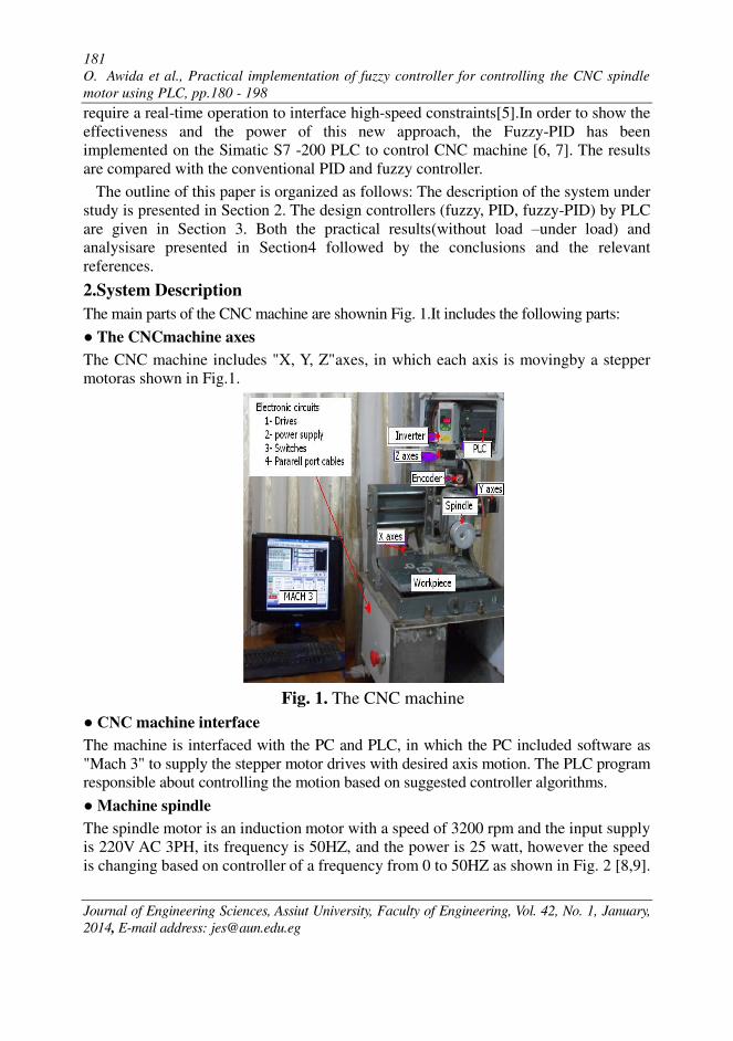
The main parts of the CNC machine are shownin Fig. 1.It includes the following parts:
● The CNCmachine axes
The CNC machine includes "X, Y, Z"axes, in which each axis is movingby a stepper
motoras shown in Fig.1.
Fig. 1. The CNC machine
● CNC machine interface
The machine is interfaced with the PC and PLC, in which the PC included software as
"Mach 3" to supply the stepper motor drives with desired axis motion. The PLC program
responsible about controlling the motion based on suggested controller algorithms.
● Machine spindle
The spindle motor is an induction motor with a speed of 3200 rpm and the input supply
is 220V AC 3PH, its frequency is 50HZ, and the power is 25 watt, however the speed
is changing based on controller of a frequency from 0 to 50HZ as shown in Fig. 2 [8,9].
182 O. Awida et al., Practical implementation of fuzzy controller for controlling the CNC spindle
motor using PLC, pp.180 - 198
Journal of Engineering Sciences, Assiut University, Faculty of Engineering, Vol. 42, No. 1, January,
2014, E-mail address: [email protected]
D/A
converterinverter motor
The encoder
s ref +
-
- rpm - pls
e(t)
pls ( - )v dc ( ~ )Hz ( - ) rpmout
error
s out
s out
U(t)
PLC
Controller
High Speed counter
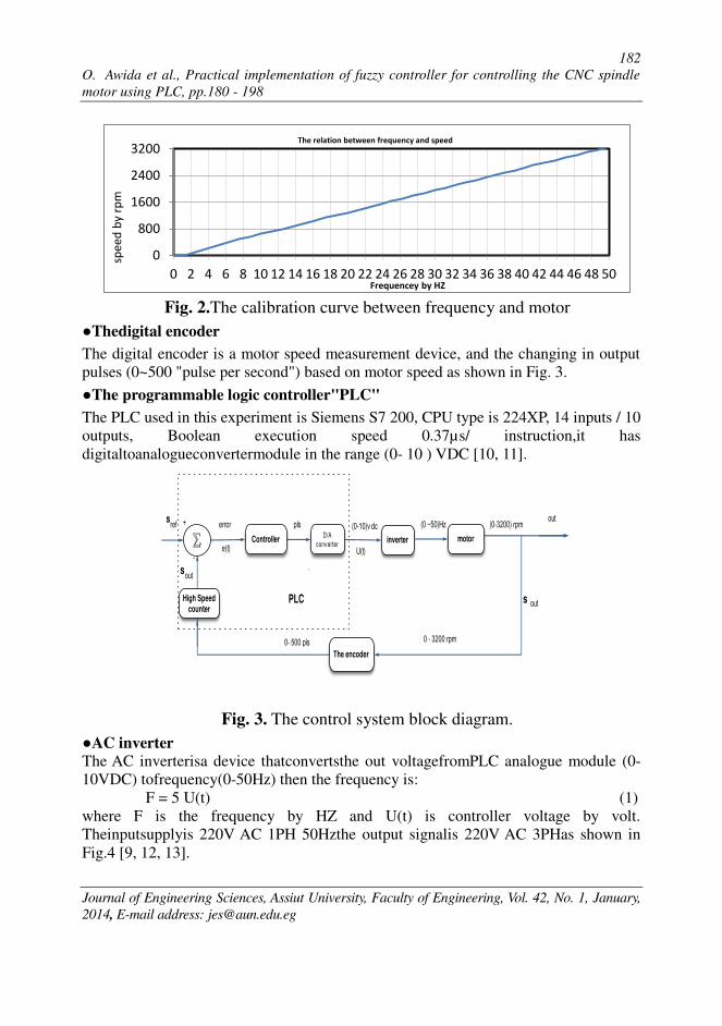
Fig. 2.The calibration curve between frequency and motor
●Thedigital encoder
The digital encoder is a motor speed measurement device, and the changing in output
pulses (0~500 "pulse per second") based on motor speed as shown in Fig. 3.
●The programmable logic controller"PLC"
The PLC used in this experiment is Siemens S7 200, CPU type is 224XP, 14 inputs / 10
outputs, Boolean execution speed 0.37µs/ instruction,it has
digitaltoanalogueconvertermodule in the range (0- 10 ) VDC [10, 11].
Fig. 3. The control system block diagram.
●AC inverter
The AC inverterisa device thatconvertsthe out voltagefromPLC analogue module (0-
10VDC) tofrequency(0-50Hz) then the frequency is:
F = 5 U(t) (1)
where F is the frequency by HZ and U(t) is controller voltage by volt.
Theinputsupplyis 220V AC 1PH 50Hzthe output signalis 220V AC 3PHas shown in
Fig.4 [9, 12, 13].
0
800
1600
2400
3200
0 2 4 6 8 10 12 14 16 18 20 22 24 26 28 30 32 34 36 38 40 42 44 46 48 50
The relation between frequency and speed
Frequencey by HZ
spe
ed
by
rp
m

183
O. Awida et al., Practical implementation of fuzzy controller for controlling the CNC spindle
motor using PLC, pp.180 - 198
Journal of Engineering Sciences, Assiut University, Faculty of Engineering, Vol. 42, No. 1, January,
2014, E-mail address: [email protected]
The inverter
pls
- v
U(t)
-phase
v AC
HZ - +
ic
ib
Ta Tb Tc
Va Vb Vc
The controller
Voltage Command
Generator
ia
Induction
motor
Plus Wides
Modulation
+
- D/A
Converter
-phase
v AC
HZ
inverterRectifier
Fig.4.Block diagram for the inverter
3. PID and Fuzzy Controllers Implementation using PLC
3.1 PID controller
The PID controller regulates the value of the output to drive the error e(t) to zero. A
measure of the error is given by the difference between the set-point (the desired
operating point), and the process variable (the actual operating point) [14]. The
principle of PID control is based upon the following equation that expresses the output, U(t) as a function of a proportional term, an integral term, and a differential term as
follows: U(t) = U t i i ia + k e (t) + k ∫ e t dt+ k de t /dt (2)
where U (t) is the loop output controller PID as a function of time, k is the loop gain,
e(t) is different between the set-point speed Sr and the actual speed of the induction
spindle motor S , and U t i i ia is the initial value of the loop output [15].
In order to implement this control function in a digital computer, the continuous
function must be quantized into periodic samples of the error value with subsequent
calculation of the output. The corresponding equation, which is the basis for the digital
computer solution, is: U(k)= U(k-1)+k e(k)+ k TS /TI∑ e k + k TD/TS(e(k)-e(k-1)) (3)
whereU(k) is the output of the controller of the PID at sample time k, TS ,TI and TD are the loop sample time, the integral time, and the derivative time respectively.
Since the digital computer must calculate the output value each time the error is
sampled beginning with the first sample, it is only necessary to store the previous value
of the error and the previous value of the integral term. Because of the repetitive nature

184 O. Awida et al., Practical implementation of fuzzy controller for controlling the CNC spindle
motor using PLC, pp.180 - 198
Journal of Engineering Sciences, Assiut University, Faculty of Engineering, Vol. 42, No. 1, January,
2014, E-mail address: [email protected]
of the digital computer solution, a simplification in the equation that must be solved at
any sample time can be made. The simplified equation is: U(k)= U(k-1)+k e(k)+ ki ∑ e k + k (e(k)-e(k-1)) (4)
where ki = k TS /TI and k = k TD/TS .
3.2. Fuzzy control
In order to establish a proper fuzzy an expert experiences and knowledge is
necessary for the membership functions and fuzzy rules [16]. We need to control the
speed of the spindle motor by changing the input voltage. When a set-point is defined,
if for some reason, the motor runs faster, we need to slow it down by reducing the input
voltage. If the motor slows below the set-point, the input voltage must be increased so
that the motor speed reaches the set-point, this method is known by fuzzy. The inputs
have a set of possible linguistic values {NH, NL, Z, PL, PH}, NH stands for Negative
High, NL stands for Negative Low, Z stands for Zero, PL stands for Positive
LowandPH stands for Positive High.
The output changing of voltage isδU(k), which is added to the reference value in
order to eliminate the deviation between the system output and the desired value. It has
a set of possible linguistic values {TSD, SD, NG, SP, TSD,} where TSD stands for Too
Speed Down, SD stands for Speed Down, NG stands for No Change, SP stands for
Speed Up andTSP stands for Too Speed Up as shown in Table 1 and Fig. 5.
Table1.
Fuzzy rule table Change of error Δe (k)
e(k
)
e ∆e NH NL Z PL PH
NH TSD TSD TSD SD NG
NL TSD TSD SD NG SP
Z TSD SD NG SP TSP
PL SD NG SP TSP TSP
PH NG SP TSP TSP TSP

185
O. Awida et al., Practical implementation of fuzzy controller for controlling the CNC spindle
motor using PLC, pp.180 - 198
Journal of Engineering Sciences, Assiut University, Faculty of Engineering, Vol. 42, No. 1, January,
2014, E-mail address: [email protected]
NH�(� %)
RPM
NL
Actual pointError e(k)- MAX e(k) MAX e(k)
- - - -�
�PHPLZ
NH
RPM
NL
Actual point
change of error Δe(k)
- MAX Δe(k)MAX Δe(k)
- - - -�
�PHPLZ
TSD
volt
SD
controller
change of voltage δU(k)
- MAX δU(k) MAX δU(k)
. .� . . - .�- .� - . - .
�TSPSPNG
Fig. 5. Membership functions
● Software design
A PC and PLC control system is employed to realize CNC spindle motor motion
control, which contains a personal computer (PC). The PC sends initialization
commands to the PLC in advance, and sends parameter signals to each individual
drivers afterwards, such as operation modes, motor speeds and spindle rotation
directions. The spindle is driven by the corresponding driver, and feedback the real-
time status to the PLC and the PC. The parameters of the spindle motor display on the
PC, and the real-time motion is controlled by the PLC.
The S7-200 of micro-programmable logic controllers (Micro PLCs) is used to control
the CNC spindle motor, the programming language is the STEP 7-Micro/WIN 32
Ladder Logic (LAD) editor.The Fig.6 shows the blockdiagram. The print out ofthe first
page of the fuzzy ladderprogram is shown in the appendix.

186 O. Awida et al., Practical implementation of fuzzy controller for controlling the CNC spindle
motor using PLC, pp.180 - 198
Journal of Engineering Sciences, Assiut University, Faculty of Engineering, Vol. 42, No. 1, January,
2014, E-mail address: [email protected]
Fig. 6.Block diagram of the ladder program of fuzzy logic controller
implementation.
To save the real time reading from PLC to PC (Excel program) by use the Softing
S7/S5 OPC Server, The Softing S7 OPC server gives you quick, convenient access to
the entire SIMATIC S7 series as well as Siemens WinAC and compatible controllers
from other manufactures, the OPC client applications can access the input or output
data, flags, timers, counters, etc. of several controllers at once via familiar S7-200.
The following steps show the fuzzy controller designed by PLC:
Step1: Given the reference speed Sr to the program PLC and save in data register.
Step2: The values of memberships for e (k),Δe(k)and δU(k) given to program PLC.
Step3:The measurement actual out speed of motor S is save in data register.
Step4: Determine the error e(k) and Δe(k) as follows:
e (k) = Sr - S (5)
Δe (k) =e (k) – e (k-1) (6)
PLC
The encoder
Determine the
change of error
Δe(k)
Enter
the reference
speed
Determine the
error e(k)
Find membership function A(x) for
e(k) and Δe(k)
Calculating the applicability degree
Defuzzification δU(x)
The fuzzy out U(k)
COMPUTER
OUTPUT
VOLTAGE
Enter
memberships for
e(k)
Enter
memberships for
Δek)
Enter
memberships for
δU(k)
actual output
speed
inverter and motor
High Speed
Counter
187
O. Awida et al., Practical implementation of fuzzy controller for controlling the CNC spindle
motor using PLC, pp.180 - 198
Journal of Engineering Sciences, Assiut University, Faculty of Engineering, Vol. 42, No. 1, January,
2014, E-mail address: [email protected]
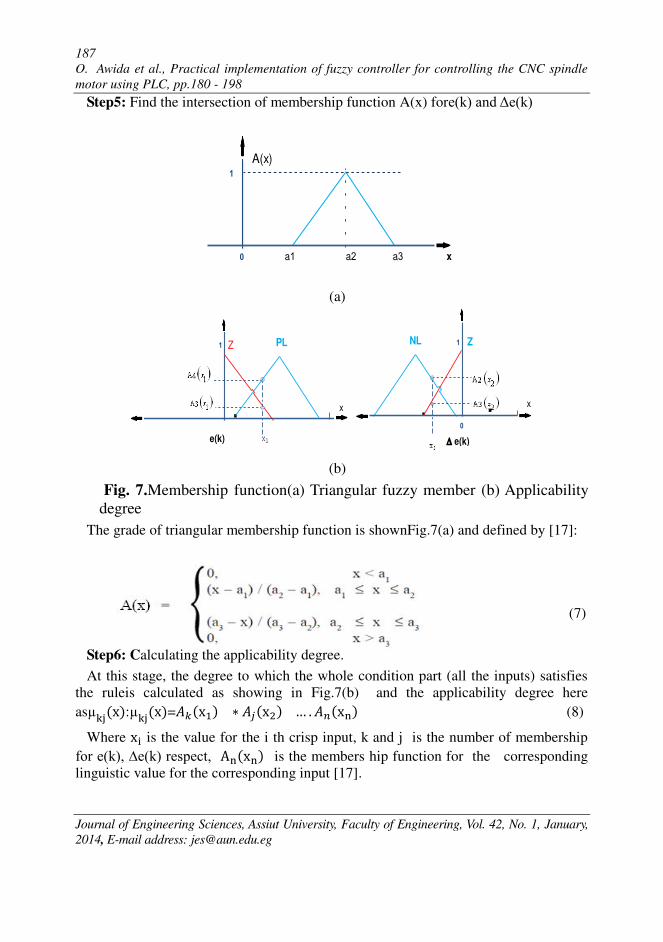
Step5: Find the intersection of membership function A(x) fore(k) and Δe(k)
xa
�
a a
A(x)
(a)
e(k)
x
�NL Z
e(k)
x
� Z PL
(b)
Fig. 7.Membership function(a) Triangular fuzzy member (b) Applicability
degree
The grade of triangular membership function is shownFig.7(a) and defined by [17]:
(7)
Step6: Calculating the applicability degree.
At this stage, the degree to which the whole condition part (all the inputs) satisfies
the ruleis calculated as showing in Fig.7(b) and the applicability degree here
as : =� ∗ � … . �� (8)
Where i is the value for the i th crisp input, k and j is the number of membership
for e(k), ∆e(k) respect, A is the members hip function for the corresponding
linguistic value for the corresponding input [17].
188 O. Awida et al., Practical implementation of fuzzy controller for controlling the CNC spindle
motor using PLC, pp.180 - 198
Journal of Engineering Sciences, Assiut University, Faculty of Engineering, Vol. 42, No. 1, January,
2014, E-mail address: [email protected]
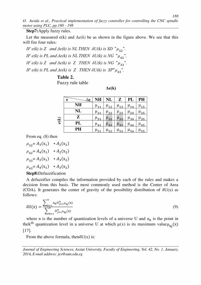
Step7:Apply fuzzy rules.
Let the measured e(k) and Δe(k) be as shown in the figure above. We see that this
will fire four rules:
IF e(k) is Z and Δe(k) is NL THEN δU(k) is SD "µ ". IF e(k) is PL and Δe(k) is NL THEN δU(k) is NG "µ ". IF e(k) is Z and Δe(k) is Z THEN δU(k) is NG "µ ". IF e(k) is PL and Δe(k) is Z THEN δU(k) is SP"µ ".
Table 2.
Fuzzy rule table Δe(k)
e(k)
e ∆e NH NL Z PL PH
NH
NL
Z
PL
PH
From eq. (8) then
µ = � ∗ �
µ = � ∗ �
µ = � ∗ �
µ = � ∗ �
Step8:Defuzzification
A defuzzifier compiles the information provided by each of the rules and makes a
decision from this basis. The most commonly used method is the Center of Area
(COA). It generates the center of gravity of the possibility distribution of δU(x) as
follows:
δU =∑ ∑ (9)
where n is the number of quantization levels of a universe U and is the point in
thek h quantization level in a universe U at which µ(x) is its maximum value
[17].
From the above formula, thenδU(x) is:

189
O. Awida et al., Practical implementation of fuzzy controller for controlling the CNC spindle
motor using PLC, pp.180 - 198
Journal of Engineering Sciences, Assiut University, Faculty of Engineering, Vol. 42, No. 1, January,
2014, E-mail address: [email protected]
D /A conv erter motor
encoder
+
-
- rpm - pls
e(k)U (k)
( - )v dc ( ~ )Hz ( - ) rpm
U (t)
PLC
Fuzzy controller
inverterPID
controller
s ref
s out
δU(k)
s out
High Speed Counter
δU = SD∗µ ∗µ ∗µ S ∗µ
Step9:The fuzzy out
The control action out U(k) can be determined as:
U (k) = U a + δU(x) (10)
whereU a is the calibrated voltage of the reference speed Sr . 3.3. Fuzzy-PID controller
In order to achieve high performance under specified operating condition a
combination between fuzzy controller and conventional PID controlleris proposed as
shown as Fig. 8, in which the fuzzy controller achieves improvement in the transient
response and the PID controller impress the performance in the steady state [18-22].
The controller that is given in eq. (10) is modified to be:
U (k) =U1(k) +δU(x) (11)
WhereU1 (k) is the control signal ofconventional PID controller and δU(x) is defined
as in eq. (9).
Fig. 8. Fuzzy-PID controller
4. Practical Results
In this section,the controller is tested in two cases:firstly, incase starting without load,
secondly incase the controller systems are under load. The RMS error is used as a
measure for the controller's performance as:
RMS =√ ∑ Sr k − S k = (12)
Where N is the number of the sample points,Sr k is the speed set-point and S k is the actual output speed [12].

190 O. Awida et al., Practical implementation of fuzzy controller for controlling the CNC spindle
motor using PLC, pp.180 - 198
Journal of Engineering Sciences, Assiut University, Faculty of Engineering, Vol. 42, No. 1, January,
2014, E-mail address: [email protected]
4.1.System response without load In the beginning we indicate four references for speed set-point(speed 0 rpm ,1000
rpm,1700 rpm and 2420 rpm), then we implementthe three controller systems PID,
fuzzy and fuzzy-PID as shown in Fig. 9.
Fig. 9.Controllers results without load between the speed set-pointSr and the
actual output speed S . Fig. 9 shows the response of the CNC spindle motor without load for the PID, the
fuzzy and the fuzzy -PID controllers under reference changes. It is clear that the PID
controller has good results in steady state but there is an overshoot occurs when the set-
point changes from a step to another. The fuzzy controller has good results in transient
state term, there is no overshoot in the output when the set-point changes from a step to
the other but there is a steadystate error. The fuzzy -PID controller has good results in
the transient and in the steady state in which the output of the system is matched with
variable set points.

191
O. Awida et al., Practical implementation of fuzzy controller for controlling the CNC spindle
motor using PLC, pp.180 - 198
Journal of Engineering Sciences, Assiut University, Faculty of Engineering, Vol. 42, No. 1, January,
2014, E-mail address: [email protected]
4.2. Control systemunderload
The three controller systems are tested using different loads with different depths of
cutting at 0mm, 2mm, 4mm and 6mm, the processed material is PVC (PolyVinyl
Chloride) material, and the cutting tool's type is Carbide flat withan end mill diameter
6 mm.
Case 1: The controller systems are tested using four references of speed set-points (speed 0
rpm, 1000 rpm, 1700 rpm and 2420 rpm) with one depth of cutting at 4 mm.
Fig. 10 shows the open loop, PID, fuzzy and fuzzy -PID controller's responses of the
CNC spindle motor under change of Sr with fixed cutting depth 4mm. In the case
of open loop, the motor is stopped, in which the PID controller causes high overshot
and fuzzy controller causes high error in the steady state, in which the fuzzy-PID
controller is better.
Fig. 10. The controller systems results under load (depth of cutting at 4 mm)
192 O. Awida et al., Practical implementation of fuzzy controller for controlling the CNC spindle
motor using PLC, pp.180 - 198
Journal of Engineering Sciences, Assiut University, Faculty of Engineering, Vol. 42, No. 1, January,
2014, E-mail address: [email protected]
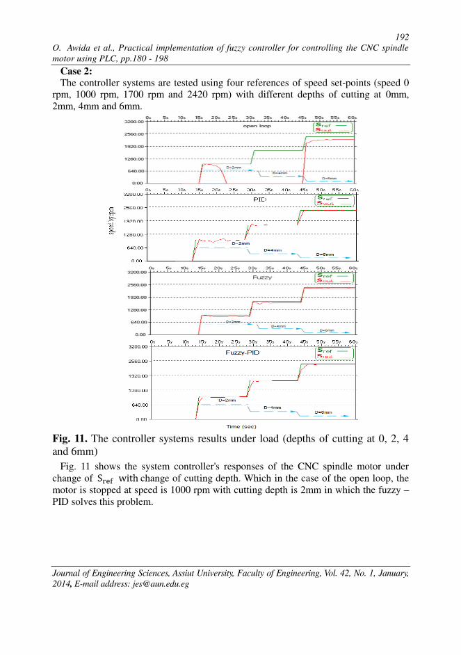
Case 2:
The controller systems are tested using four references of speed set-points (speed 0
rpm, 1000 rpm, 1700 rpm and 2420 rpm) with different depths of cutting at 0mm,
2mm, 4mm and 6mm.
Fig. 11. The controller systems results under load (depths of cutting at 0, 2, 4
and 6mm)
Fig. 11 shows the system controller's responses of the CNC spindle motor under
change of Sr with change of cutting depth. Which in the case of the open loop, the
motor is stopped at speed is 1000 rpm with cutting depth is 2mm in which the fuzzy –PID solves this problem.

193
O. Awida et al., Practical implementation of fuzzy controller for controlling the CNC spindle
motor using PLC, pp.180 - 198
Journal of Engineering Sciences, Assiut University, Faculty of Engineering, Vol. 42, No. 1, January,
2014, E-mail address: [email protected]
Case 3
The controller systems are tested using one reference of speed set-point (2420 rpm)
with different depths of cutting at 0 mm, 4mm and 6 mm.
(a) Time (Sec)

194 O. Awida et al., Practical implementation of fuzzy controller for controlling the CNC spindle
motor using PLC, pp.180 - 198
Journal of Engineering Sciences, Assiut University, Faculty of Engineering, Vol. 42, No. 1, January,
2014, E-mail address: [email protected]
(b) Time (sec)

195
O. Awida et al., Practical implementation of fuzzy controller for controlling the CNC spindle
motor using PLC, pp.180 - 198
Journal of Engineering Sciences, Assiut University, Faculty of Engineering, Vol. 42, No. 1, January,
2014, E-mail address: [email protected]
(c) Time (sec)
Fig. 12.Controller resultsundera load at depths 0, 4 and 6 mm (a) the speed set-
point Sr and the actual output speed S (b) The controller signal U (t) (c)
The error e (t)
Fig. 12 shows the open loop, PID, fuzzy and fuzzy -PID controller's responses of the
CNC spindle motor under cutting depth changes. In the case of open loop, the RMS =
165.5 rpm andthe E max (MAX error) = (max error/set-point) %is 7.89 %. The PID
parameters k = 0.9, ki=0.1 and k =0.001 are tuned using auto tuning algorithm of PID
ladder block s7 200, the details of who using this blockis given [15]. The PID
controller possesses good results in the steady state, where the actual output close to
the desired output but there is an overshoot when the cutting depth changes from a step
to another.
It is clear that the fuzzy controller has good results in the transient, and there is no
overshoot in the output when the cutting depth changes from a step to another but it

196 O. Awida et al., Practical implementation of fuzzy controller for controlling the CNC spindle
motor using PLC, pp.180 - 198
Journal of Engineering Sciences, Assiut University, Faculty of Engineering, Vol. 42, No. 1, January,
2014, E-mail address: [email protected]
results in a steady state error. The fuzzy - PID controller possess good results in the
transient and in the steady state, the output of the system under different cutting depths
are almost the same to the desired output which the RMS decrease to 8.3 rpm and
MAX error (E max) is 0.99 %, as shown in Fig. 13. The RMS and MAX error (E max)
are indicated in Table 3.
Fig.13.The results ofopen loop, PID, fuzzy and fuzzy-PID controller under load
at depths 0,4 and 6 mm
Table 3.
Comparison between different types of controllersunderload.
speed
2420
rpm
Cutting depth= 0 mm Cutting depth= 4 mm Cutting depth= 6 mm
Open
loop PID fuzzy
Fuzzy-
PID
Open
loop PID Fuzzy
Fuzzy-
PID
Open
loop PID fuzzy
Fuzzy-
PID
RMS
(rpm) 70.53 2.68 5.2 3.39 76.76 17.9 12.6 6.76 165.5 13 14.95 8.3
|Emax|% 3.06 0.29 0.29 0.25 4.54 2.36 0.91 0.74 7.89 1.78 1.36 0.99
5.Conclusions
Inthispaper,thespeedofaspindlemotorinaCNCmachineiscontrolledexperimentally by
means of three controllers, PID, fuzzy and fuzzy-PID. The system performance was
evaluated using the three controllers under different depths,0mm,4mm and 6mm. The
resultsof the fuzzy-PID controller shows good and significant improvement in the
performance over a wide range of operating conditions.
6. References
[1] C. W. de Silva, “Mechatronic Systems: Devices, Design, Control, Operation and Monitoring,” CRC Press (Taylor & Francis Group), 2008.
[2] K. B. Jin, T. Y. Doh, J. R. Ryoo and M. J. Chung, “Robust Direct Seek Control for High-
Speed Rotation Optical Disk Drives,” IEEE Trans. on Consumer Electronics, vol. 44,
Issue. 4, pp. 1273-1283, November 1998.

197
O. Awida et al., Practical implementation of fuzzy controller for controlling the CNC spindle
motor using PLC, pp.180 - 198
Journal of Engineering Sciences, Assiut University, Faculty of Engineering, Vol. 42, No. 1, January,
2014, E-mail address: [email protected]
[3]Q.Zhanga, S. Lia, and J.Guo, “Smooth Time-optimal Tool Trajectory Ggeneration for CNC Manufacturing
Systems,” Journal of Manufacturing Systems, vol. 31, Issue 3, pp. 280–287, July 2012.
[4] H. Ying, “Fuzzy Control and Modeling, Analytical Foundations and Applications,” USA:
Institute of Electrical and Electronic Engineers Inc., 2000.
[5]M. Hassan and M. F. Sharif, “Design of FPGA Based PID-like Fuzzy Controller for Industrial
Applications,” IAENG International Journal of Computer Science, vol. 34, no. 2, IJCS_34_2005.
[6] N. Buyurgan, C. Saygin, “Application of the Analytical Hierarchy Process for Real-time
Scheduling and Part Routing in Advanced Manufacturing Systems,” Journal of Manufacturing Systems, vol. 27, Issue 3, pp. 101-110, July 2008.
[7] O. Karasakal, E. Yesil, M. Guzelkaya and I. Eksin, “Implementation of A new Self-tuning Fuzzy PID
Controller on PLC,” Turkish Journal of Electrical Engineering, vol. 13, no. 2, pp. 277-286, 2005.
[8]R. Arulmozhiyal and K. Baskaran, “Speed Control of Induction Motor using Fuzzy PI and
Optimized using GA,” International Journal of Recent Trends in Engineering, vol. 2, no.
5, November 2009.
[9] M. Suetake and I. N. Silva, “Embedded DSP-Based Compact Fuzzy System and Its
Application for Induction-Motor V/f Speed Control,” IEEE Transactions on Industrial Electronics vol. 58, no. 3, March 2011.
[10] G. Godena and M. Colnaric, “Exception Handling for PLC-Based Process Control
Software,” Microprocessors and Microsystems, vol. 24, pp. 407-414, 2000.
[11] F. J. Lin and P. H. Chou, “Adaptive Control of Two-axis Motion Control System Using
Interval Type-2 Fuzzy Neural Network,” IEEE Trans. Inst. Elect., vol. 56, no. 1, January
2009.
[12] E. Ye_sil, M. G¨uzelkaya, and I. Eksin, “Self-Tuning Fuzzy PID-type Load-Frequency
Controller,” Electrical Conversion and management, vol. 45, no. 3, pp. 377-390, 2004.
[13] R. Arulmozhiyal and K. Baskaran, “Space Vector Pulse Width Modulation Based Speed Control of Induction Motor Using Fuzzy PI Controller,” International Journal of Computer and Electrical Engineering, ISSN 1793-8198, no. 1, pp. 98-103, Number 1,
2009.
[14] H. P. Huang, M. L. Roan, and J. C. Jeng, “On-line Adaptive Tuning for PID Controllers,” IEEE Proc.-Control Theory Appl., vol. 149, no 1, pp. 60-67, 2002.
[16] I. Eksin, M. G¨uzelkaya, and F. G¨urleyen, “A new Methodology for Deriving The rule-
base of a Luzzy Logic Controller with A new Internal Structure,” Engineering Applications of Artificial Intelligence, vol. 14, no. 5, pp. 617-628, 2001.
[17] L. Reznik“Fuzzy Controllers,” British Library Cataloguing in Publication Data ISBN 0 7506 3429 4.
[18] J. X. Xu, C. C. Hang, and C. Liu, “Parallel Structure and Tuning of a Fuzzy PID Controller,” Automatica, vol. 36, pp. 673-684, 2000.
[19] H. M. Khalil and M. El-Bardini, “Implementation of Speed Controller for Rotary Hydraulic Motor Based on LS-SVM,” Expert Systems with Applications,vol. 38, pp.
14249–14256, 2011.
[20] J. X. Deng, Z. l. Zhang, and H. ming, “Simulation of Synchronous Excitation Controller Based on Fuzzy-PID Control,” Relay, vol. 35, no. 19, pp. 13-15, 21, 1 Oct., 2007.
[21] T. H. cheng , L. Z. xin, W. Z. tao, Z. X. qing , and Su, Yi, “a Fuzzy PID Control System Electric,” Machines and Control, vol. 9, no. 2, pp. 136-138, March 2005.
[22] Zulfatman and M. F. Rahmat, “Application of Self-tuning Fuzzy PID Controller on
Industrial Hydraulic Actuator Using Systems Identification Approach,” International Journal on Smart Sensing and Intelligent Systems, vol. 2, no. 2, June 2009.

198 O. Awida et al., Practical implementation of fuzzy controller for controlling the CNC spindle
motor using PLC, pp.180 - 198
Journal of Engineering Sciences, Assiut University, Faculty of Engineering, Vol. 42, No. 1, January,
2014, E-mail address: [email protected]
[1] Appendix The first page of fuzzy program ladder
ي لحا يق عم لتحكم في سرع ماتور الحفر لمكين كم غيمي تطرمج المنطقيأب(CNC) خراط اتوماتيك ستخدا وحد التحكم الم
خص ال العربى:م
ةيلدد عتددعلالتحي لفعالهدد ا اليسي دد ذددا بدد ا اللتددي بددع ال لحيدد الحفادد لتددعة لاتحددع ادد ددي ذ دد خ ا د دد ت الدد تب الفليذميدد الفلوذيدد ح د لدد يتدد أبة غيف تدد تيددفي ددع(CNC)الخياطدد لح ثلعت ي ه اثلدع ال غد و د لد لحد ست ا دلع ذلهدع ت يدي فدو التحيادت يدي دي ذعتعل تحيض
ق تيدو الد اقعفده اد تاحده اد دي بد ا ذعتعل ال ي اددجعس شعاس ف الخعذ ذفع يؤثي ا ي دذفع اش في يحعس بعل أثيي ال ال ا جعست الفل ج حفح ب ا اللتي ت توليو ثاثد ا مفد ذدا ذعتعل
الحفايد الل دعسج د تد اذد ( PID,FUZZY,FUZZY-PID)دبد ذعتدعل ا مف ال تب الحفاي اد بد ا :الحفاي ف عاتالل عسج ذعضح ف اللتي داذ ت ب ت ا لدتي ت تيفيف دتيليح ةفع بع
ف عل توليو ا فع دت توليذهع فد ثدا دثع يع ف عل توليو ا فع ذ ت يي ال ي عتادا ت يي اا فع ذد ثلدعت -3السرعات يياا فع ذ ت يي -2 ثلعت اا فع ذ ت يي ال ي عت -1 عات
الل ددعسج فدد علدد دد توليددو ا ذددا ا مفدد الدد تب ح دفدد اللهعيدد تدد فددو ال ددي عت دةدد ال تدد اذدد ذذعل عت بيله جفيحع دا طييدو ااشدبع دالت دعبعت دالمد اد دفد اللهعيد تد ال علدي بعف دو مدع
تولذع اف و الل عسج . (FUZZY_PID) تتب دبع مع


![Learning a Fuzzy Controller by Genetic Algorithms · A fuzzy controller consists of a set of fuzzy control rules with appropriate inference mechanisms [1]. The fuzzy controller is](https://img.pdfslide.net/doc/110x75/5fdb09ef9cebd6099d5e2885/learning-a-fuzzy-controller-by-genetic-a-fuzzy-controller-consists-of-a-set-of-fuzzy.jpg)