Embed Size (px)
Citation preview
4 2 9
14TH CANAD IAN CONFERENCE ON BU I LD ING S C I ENCE AND T E CHNOLOGY
PRACTICAL ISSUES ASSOICATED WITH THE USE OF INFRARED
THERMOGRAPHY FOR DETECTION OF HEAT, AIR AND
MOISTURE DEFICIENCIES IN BUILDING ENVELOPES
G. B. McIntosh
ABSTRACT
Thermal infrared cameras have been used for more than 40 years in helping diagnose problems related to
heat, air or moisture deficiencies in buildings. But in the past 10 years significant advances have been made
in the performance, size, weight and cost reduction of cameras to the point where entry level cameras suitable
for some building investigations, are less than $3,000, and in coming years will be even less expensive.
This has led to the proliferation of its use as a building diagnostic tool. Unfortunately this has also led to
the misunderstanding of how this technology should be properly utilized, and the mis-belief that there is
such a thing as an “all-in-one” building diagnostic scan, and/or that an investigation can be performed any
time of day or year. Irrespective of how good the camera performance is, there are different minimum
environmental conditions and specific inspection methodologies required for the reliable detection of heat,
air and moisture problems for various types of construction. In addition, while thermography can be a very
useful qualitative tool, other methods and tools must be used for quantification of actual amounts of excessive
heat flow, air flow, or moisture content. This paper will discuss the limitations of utilizing thermal imaging
as a building diagnostic tool, the appropriate and separate methodologies that should be employed for heat,
air and moisture deficiencies, the various standards and protocols that should be followed, and the
complementary quantitative and verification tools that should be used in conjunction with thermography.
This paper will try to be as subjective as possible by referencing Canadian and International standards related
to building inspections using thermography. This includes historical, current and in-progress standards from
National Master Specifications of Canada, ASTM, RESNET and ISO.
INTRODUCTION
Thermography can and has been utilized in the discovery of otherwise undetectable heat, air and moisture
anomalies in buildings. Unfortunately, thermography only is applicable when these anomalies affect
detectable surface temperature patterns. It therefore requires suitable thermodynamic conditions sometimes
unique to the environment, materials, assembly, or operation of the building in order to discover an anomaly
related to a specific heat, air, or moisture deficiency. This creates limitations on the time, location, camera
detection capabilities, and operator expertise required for suitable, reliable and repeatable detection. This
paper will discuss practical considerations for detection of thermal anomalies in each of three categories.
For each topic we will discuss the limitations, challenges and requirements for the use of this building
diagnostic tool.
DETECTING THERMAL ANOMALIES RELATED TO CONDUCTIVE HEAT TRANSFER
Thermographic evaluations for conductive thermal anomalies (e.g.: insulation quantity, quality, deficiency,
thermal bypasses) may be conducted in heat loss (winter) or heat gain (summer) conditions so long as there
is a minimum steady state temperature difference maintained between the inside and outside of the structure.
Evaluation is based upon Fourier’s law of conduction: heat flux, Q = (k/L)·ΔT (Incropera, et al, 1996). Hence
any thermal anomaly detected as a surface temperature variance under constant steady state temperature
12 CCBST 2014 Proceedings Book_v10 A6 403-438_Layout 1 14-10-17 4:08 PM Page 429
4 3 0
14TH CANAD IAN CONFERENCE ON BU I LD ING S C I ENCE AND T E CHNOLOGY
difference (ΔT) must be attributable to a variance in material conductivity (k) or thickness (L). ASTM
C1060, ISO 6781, and RESNET standards specify a minimum of 10ºC difference across the enclosure. The
Canadian National Master Specifications NMS 022713 requires a minimum difference of 15ºC, although
NMS standards are aimed more towards commercial and institutional buildings where buffer spaces (e.g.
ceiling plenums, vented rain-screens) and thicker more complex construction is common. All standards
require steady state conditions lasting at least 3 to 4 hours (longer in some standards under certain conditions)
to eliminate transient surface thermal patterns influenced by material thermal capacitance storing or releasing
energy. Most standards require the inspection be conducted from both interior and exterior perspectives,
although most note that an interior inspection will usually provide better, more stable information,
particularly in conventional construction where the insulation is typically placed closer to the interior than
the exterior surfaces. Irrespective of whether it is an inside or outside inspection, transient environmental
conditions, particularly those caused by solar loading and wind, may confuse actual insulation conductive
performance, and/or cause conductive deficiencies to go undetected.
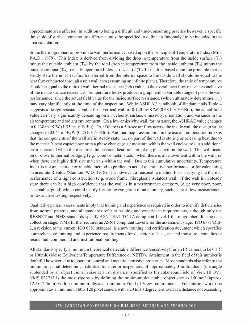
Most standards refer to thermographic assessments as being qualitative in which different types of insulation
anomalies and construction deficiencies related to thermal conduction will exhibit unique surface temperature
patterns. Most standards refer to the use of a known thermal conductivity bypass (e.g. wood studs) as a
qualitative thermal performance reference. In conventional wood frame construction the wood studs will
exhibit a regular consistent pattern of lower performance relative to the insulation. In a normal insulated
wall, when an inside wall is viewed under heat loss conditions the studs will appear cooler than the insulation
(Photo 1a), while in summertime the polarity will be reversed and the studs will appear warmer than the
insulation (Photo1b).
Accurate quantitative heat transfer performance (conductance or equivalent R value) cannot be derived from
a thermal image and/or temperature values alone. If this is desired it should be done in accordance with
ASTM C1046 – 95 and ASTM C1155 – 95. The only part that thermography plays in ASTM C1046 is to
determine the placement of the heat flow devices and measurements. Since the total enclosure heat loss is
affected by the total surface area multiplied by the unit heat flux, then thermography can also be useful for
estimating the total area affected by either one localized conductive anomaly, or the sum of repetitive
anomalies. RESNET, however, is the only standard which suggests a quantitative approach of determining
12 CCBST 2014 Proceedings Book_v10 A6 403-438_Layout 1 14-10-17 4:08 PM Page 430
4 3 1
14TH CANAD IAN CONFERENCE ON BU I LD ING S C I ENCE AND T E CHNOLOGY
approximate area affected. In addition to being a difficult and time-consuming practice however, a specific
threshold of surface temperature difference must be specified to define an “anomaly” to be included in the
area calculation.
Some thermographers approximate wall performance based upon the principle of Temperature Index (Mill,
P.A.D., 1979). This index is derived from dividing the drop in temperature from the inside surface (Tis)
minus the outside ambient (Toa) by the total drop in temperature from the inside ambient (Tia) minus the
outside ambient (Toa), i.e.: Temperature Index = (Tis-Toa) / (Tia-Toa). It is based upon the principle that in
steady state the unit heat flux transferred from the interior space to the inside wall should be equal to the
heat flux conducted through a unit wall area (assuming an infinite plane). Therefore, the ratio of temperatures
should be equal to the ratio of wall thermal resistance (L/k) value to the overall heat flow resistance inclusive
of the inside surface resistance. Temperature Index produces a graph with a variable range of possible wall
performance, since the actual field value for the inside surface resistance, (which ultimately determines Tis)
may vary significantly at the time of the inspection. While ASHRAE handbook of fundamentals Table 4
suggests a design resistance value for a vertical wall of 0.120 m2·K/W (0.68 hr·ft2·F/Btu), the actual field
value can vary significantly depending on air velocity, surface emissivity, orientation, and variance in the
air temperature and radiant environment. On a low emissivity wall, for instance, the ASHRAE value changes
to 0.238 m2·K/W (1.35 hr·ft2·F/Btu). Or, if there is a 5 ft/sec air flow across the inside wall the design value
changes to 0.044 m2·K/W (0.25 hr·ft2·F/Btu). Another major assumption in the use of Temperature Index is
that the components of the wall are in steady state, i.e. no part of the wall is storing or releasing heat due to
the material’s heat capacitance or to a phase change (e.g.: moisture within the wall enclosure). An additional
error is created when there is three dimensional heat transfer taking place within the wall. This will occur
on or close to thermal bridging (e.g. wood or metal studs), when there is air movement within the wall, or
when there are highly diffusive materials within the wall. Due to this cumulative uncertainty, Temperature
Index is not an accurate or reliable method to predict an actual quantitative performance or for calculating
an accurate R value (Stainton, W.D. 1978). It is however, a reasonable method for classifying the thermal
performance of a light construction (e.g. wood frame, fibreglass insulated) wall. If the wall is in steady
state there can be a high confidence that the wall is in a performance category, (e.g.: very poor, poor,
acceptable, good) which could justify further investigation of an anomaly, such as heat flow measurement
or destructive testing respectively.
Qualitative pattern assessments imply that training and experience is required in order to identify deficiencies
from normal patterns, and all standards refer to training and experience requirements, although only the
RESNET and NMS standards specify ASNT SNT-TC-1A compliant Level 1 thermographers for the data
collection stage. NMS further requires an ASNT compliant Level 2 for the assessment stage. ISO 6781/DIS-
3, a revision to the current ISO 6781 standard, is a new training and certification document which specifies
comprehensive training and experience requirements for detection of heat, air and moisture anomalies in
residential, commercial and institutional buildings.
All standards specify a minimum theoretical detectable difference (sensitivity) for an IR camera to be 0.1ºC
or 100mK (Noise Equivalent Temperature Difference or NETD). Attainment in the field of this number is
doubtful however, due to operator control and material emissive properties. Most standards also refer to the
minimum spatial detection capabilities for interior inspections of approximately 3 milliradians (the angle
subtended by an object 3mm in size at a 1m distance) specified as Instantaneous Field of View (IFOV).
NMS 022713 is the most rigorous by defining the minimum detectable object size as 150mm2 (approx
12.5x12.5mm) within minimum physical minimum Field of View requirements. For interior work this
approximates a minimum 160 x 120 pixel camera with a 20 to 30 degree lens used at a distance not exceeding
12 CCBST 2014 Proceedings Book_v10 A6 403-438_Layout 1 14-10-17 4:08 PM Page 431
4 3 2
14TH CANAD IAN CONFERENCE ON BU I LD ING S C I ENCE AND T E CHNOLOGY
5m. RESNET has a similar spatial requirement, although somewhat relaxed in the minimum Field of View
requirement. For normal exterior work NMS requirements translate to a 320 x 240 pixel camera used at a
distance of up to about 20m, although it specifies that higher resolutions of lenses and/or pixel count may
be necessary to achieve the minimum 150mm2 resolution at longer stand-off distances. Unfortunately there
is a proliferation of low cost (under $500) thermal imagers which do not even come close to meeting these
specifications, yet are being utilized for thermographic assessments.
DETECTING THERMAL ANOMALIES RELATED TO AIR MOVEMENT
Unintentional air movement within, around, and through an enclosure may result is significant energy,
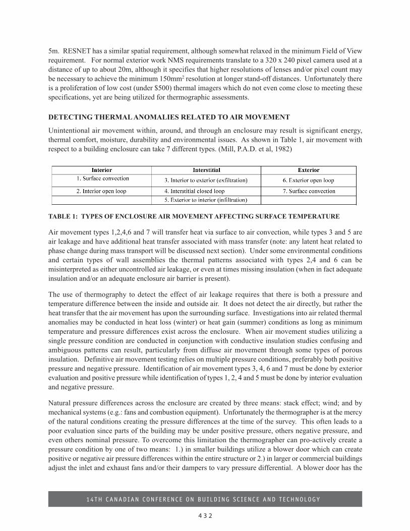
thermal comfort, moisture, durability and environmental issues. As shown in Table 1, air movement with
respect to a building enclosure can take 7 different types. (Mill, P.A.D. et al, 1982)
TABLE 1: TYPES OF ENCLOSURE AIR MOVEMENT AFFECTING SURFACE TEMPERATURE
Air movement types 1,2,4,6 and 7 will transfer heat via surface to air convection, while types 3 and 5 are
air leakage and have additional heat transfer associated with mass transfer (note: any latent heat related to
phase change during mass transport will be discussed next section). Under some environmental conditions
and certain types of wall assemblies the thermal patterns associated with types 2,4 and 6 can be
misinterpreted as either uncontrolled air leakage, or even at times missing insulation (when in fact adequate
insulation and/or an adequate enclosure air barrier is present).
The use of thermography to detect the effect of air leakage requires that there is both a pressure and
temperature difference between the inside and outside air. It does not detect the air directly, but rather the
heat transfer that the air movement has upon the surrounding surface. Investigations into air related thermal
anomalies may be conducted in heat loss (winter) or heat gain (summer) conditions as long as minimum
temperature and pressure differences exist across the enclosure. When air movement studies utilizing a
single pressure condition are conducted in conjunction with conductive insulation studies confusing and
ambiguous patterns can result, particularly from diffuse air movement through some types of porous
insulation. Definitive air movement testing relies on multiple pressure conditions, preferably both positive
pressure and negative pressure. Identification of air movement types 3, 4, 6 and 7 must be done by exterior
evaluation and positive pressure while identification of types 1, 2, 4 and 5 must be done by interior evaluation
and negative pressure.
Natural pressure differences across the enclosure are created by three means: stack effect; wind; and by
mechanical systems (e.g.: fans and combustion equipment). Unfortunately the thermographer is at the mercy
of the natural conditions creating the pressure differences at the time of the survey. This often leads to a
poor evaluation since parts of the building may be under positive pressure, others negative pressure, and
even others nominal pressure. To overcome this limitation the thermographer can pro-actively create a
pressure condition by one of two means: 1.) in smaller buildings utilize a blower door which can create
positive or negative air pressure differences within the entire structure or 2.) in larger or commercial buildings
adjust the inlet and exhaust fans and/or their dampers to vary pressure differential. A blower door has the
12 CCBST 2014 Proceedings Book_v10 A6 403-438_Layout 1 14-10-17 4:08 PM Page 432
4 3 3
14TH CANAD IAN CONFERENCE ON BU I LD ING S C I ENCE AND T E CHNOLOGY
advantage of being able to characterize the air leakage curve for the building and provide a quantitative
estimation of the amount of air leakage under average and extreme conditions. For larger buildings where
blower door use is not possible, air leakage quantification will typically be limited to evaluation via tracer
gas depletion method.
ASTM E1186-03, RESNET and NMS 022713 standards do not agree on the pressures and temperatures
differences across the enclosure required for reliable thermographic detection of air leakage. It varies from
a difference of 1.7ºC @ 10 Pa (RESNET) to 5ºC @ 10 to 50 Pa (ASTM) to the most stringent requirements
of NMS which requires a minimum of 20ºC difference when pressures are between 5 to 10 Pa and 10ºC
minimum when pressures are between 10 to 25Pa.
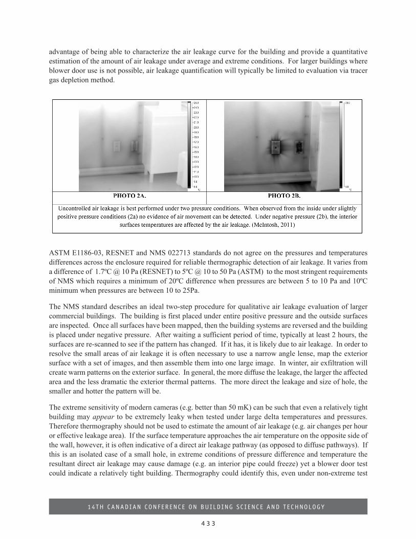
The NMS standard describes an ideal two-step procedure for qualitative air leakage evaluation of larger
commercial buildings. The building is first placed under entire positive pressure and the outside surfaces
are inspected. Once all surfaces have been mapped, then the building systems are reversed and the building
is placed under negative pressure. After waiting a sufficient period of time, typically at least 2 hours, the
surfaces are re-scanned to see if the pattern has changed. If it has, it is likely due to air leakage. In order to
resolve the small areas of air leakage it is often necessary to use a narrow angle lense, map the exterior
surface with a set of images, and then assemble them into one large image. In winter, air exfiltration will
create warm patterns on the exterior surface. In general, the more diffuse the leakage, the larger the affected
area and the less dramatic the exterior thermal patterns. The more direct the leakage and size of hole, the
smaller and hotter the pattern will be.
The extreme sensitivity of modern cameras (e.g. better than 50 mK) can be such that even a relatively tight
building may appear to be extremely leaky when tested under large delta temperatures and pressures.
Therefore thermography should not be used to estimate the amount of air leakage (e.g. air changes per hour
or effective leakage area). If the surface temperature approaches the air temperature on the opposite side of
the wall, however, it is often indicative of a direct air leakage pathway (as opposed to diffuse pathways). If
this is an isolated case of a small hole, in extreme conditions of pressure difference and temperature the
resultant direct air leakage may cause damage (e.g. an interior pipe could freeze) yet a blower door test
could indicate a relatively tight building. Thermography could identify this, even under non-extreme test
12 CCBST 2014 Proceedings Book_v10 A6 403-438_Layout 1 14-10-17 4:08 PM Page 433
4 3 4
14TH CANAD IAN CONFERENCE ON BU I LD ING S C I ENCE AND T E CHNOLOGY
conditions, because the surface temperature on the negative pressure side would be only slightly different
than the air temperature on the positive side.
Camera performance requirements specified by all Standards for air leakage detection are identical to those
for detection of conductive anomalies, with the NMS specifications being the most detailed and rigorous.
(refer to the previous section on conduction for camera specifications)
DETECTING THERMAL ANOMALIES RELATED TO MOISTURE
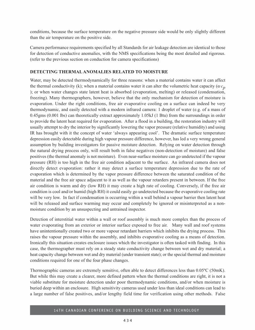
Water, may be detected thermodynamically for three reasons: when a material contains water it can affect
the thermal conductivity (k); when a material contains water it can alter the volumetric heat capacity (α·cp); or when water changes state latent heat is absorbed (evaporation, melting) or released (condensation,
freezing). Many thermographers, however, believe that the only mechanism for detection of moisture is
evaporation. Under the right conditions, free air evaporative cooling on a surface can indeed be very
thermodynamic, and easily detected with a modern infrared camera: 1 droplet of water (e.g. of a mass of
0.45gms (0.001 lbs) can theoretically extract approximately 1.05kJ (1 Btu) from the surroundings in order
to provide the latent heat required for evaporation. After a flood in a building, the restoration industry will
usually attempt to dry the interior by significantly lowering the vapor pressure (relative humidity) and using
IR has brought with it the concept of water ‘always appearing cool’. The dramatic surface temperature
depression easily detectable during high vapour pressure difference, however, has led a very wrong general
assumption by building investigators for passive moisture detection. Relying on water detection through
the natural drying process only, will result both in false negatives (non-detection of moisture) and false
positives (the thermal anomaly is not moisture). Even near-surface moisture can go undetected if the vapour
pressure (RH) is too high in the free air condition adjacent to the surface. An infrared camera does not
directly detect evaporation: rather it may detect a surface temperature depression due to the rate of
evaporation which is determined by the vapor pressure difference between the saturated condition of the
material and the free air space adjacent to it as well as the vapour retarders present in between. If the free
air condition is warm and dry (low RH) it may create a high rate of cooling. Conversely, if the free air
condition is cool and/or humid (high RH) it could easily go undetected because the evaporative cooling rate
will be very low. In fact if condensation is occurring within a wall behind a vapour barrier then latent heat
will be released and surface warming may occur and completely be ignored or misinterpreted as a non-
moisture condition by an unsuspecting and untrained inspector.
Detection of interstitial water within a wall or roof assembly is much more complex than the process of
water evaporating from an exterior or interior surface exposed to free air. Many wall and roof systems
have unintentionally created two or more vapour retardant barriers which inhibits the drying process. This
raises the vapour pressure within the assembly, and inhibits evaporative cooling as a means of detection.
Ironically this situation creates enclosure issues which the investigator is often tasked with finding. In this
case, the thermographer must rely on a steady state conductivity change between wet and dry material; a
heat capacity change between wet and dry material (under transient state); or the special thermal and moisture
conditions required for one of the four phase changes.
Thermographic cameras are extremely sensitive, often able to detect differences less than 0.05ºC (50mK).
But while this may create a clearer, more defined pattern when the thermal conditions are right, it is not a
viable substitute for moisture detection under poor thermodynamic conditions, and/or when moisture is
buried deep within an enclosure. High sensitivity cameras used under less than ideal conditions can lead to
a large number of false positives, and/or lengthy field time for verification using other methods. False
12 CCBST 2014 Proceedings Book_v10 A6 403-438_Layout 1 14-10-17 4:08 PM Page 434
4 3 5
14TH CANAD IAN CONFERENCE ON BU I LD ING S C I ENCE AND T E CHNOLOGY
negatives lead to credibility issues of both the inspector and the thermographic industry as well as the
possibilities of litigation, particularly when mold or other damage associated with the moister is present but
not detected.
Since moisture detection is not covered in much detail by any standard, a general assumption could be that
the requirements for camera performance are at least equal to those for detection of conductive anomalies.
The current consensus in the industry however, is that moisture detection necessitates a higher level of
thermal sensitivity. Most manufacturers have accommodated this by producing “building” model of IR
cameras with an NETD of at least 0.08ºC (80mK) or better. It is likely that any future standards developed
for moisture detection will require at least this level of sensitivity. Spatial requirements are likely to remain
the same as for conductive anomaly detection. The NMS standard is the only specification which itemizes
certain conditions for the detection of moisture. The standard requires a minimum 20ºC (temperature) and
25Pa (pressure) difference from the inside to the outside and 30ºC difference when the pressure difference
is less than 10Pa.
The Special Case of Low Slope Roof Moisture Detection
Both ASTM C1153-10 and NMS 022716 standards detail the conditions necessary for detection of moisture
trapped in conventional low slope built-up roofing systems. Interstitial moisture is detected using the
capacitive method of detection by observing the outside roof surface under transient conditions. Ideal
conditions are a warm sunny day with low wind, and no moisture on the roof surface. Inspection takes place
1 to 2 hours after the direct sunlight has left the roof surface and is conducted into the night. Potential wet
areas are identified as warm areas that have retained the solar heat gained during the day. Both standards
also permit investigations to be performed using the conductive method of inspection under steady state
heat loss conditions with a minimum differential of 10ºC (ASTM) or 15ºC (NMS) across the enclosure. In
all cases, and with both standards, the thermographer must be aware of inside conditions, fixtures and
appliances and no standing water should be present on the roof surface.
CONCLUSIONS
Thermography can play a significant role as a non destructive and rapid screening tool to identify potentialheat, air, and moisture related anomalies in large and small buildings, but only if the thermodynamic
12 CCBST 2014 Proceedings Book_v10 A6 403-438_Layout 1 14-10-17 4:08 PM Page 435
4 3 6
14TH CANAD IAN CONFERENCE ON BU I LD ING S C I ENCE AND T E CHNOLOGY
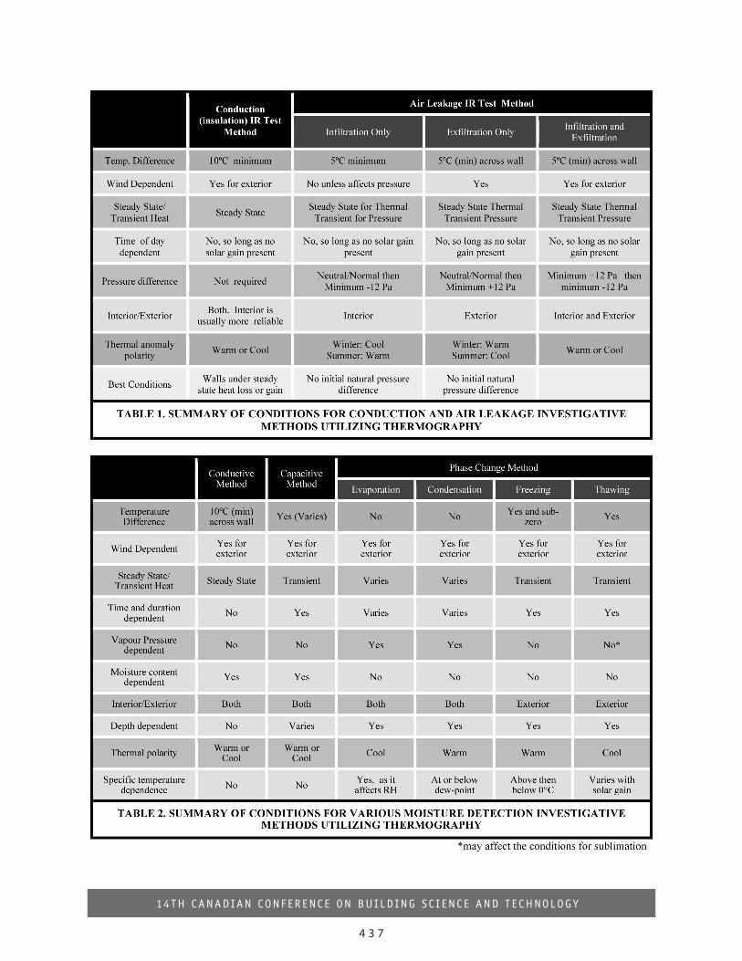
conditions are right. Thermographic results alone cannot quantify excessive heat flow, air flow, or moisture
content. The primary use for thermography should as a qualitative investigative tool, identifying potential
areas for further investigation, validation and quantification by other means. Any quantitative thermographic
analysis should be limited to that of temperature measurement and/or potential percentage area affected.
Thermographic investigations should be limited to those environmental conditions, procedures, and methods
specified and recommended by various standards established by recognized independent bodies. Standards
for utilizing thermography for conductive and air leakage studies are well established and should be adhered
to. These are summarized in Table 1. But, because of a lack of current standards for moisture detection, it
should be done carefully and with a specific methodology for detection (conduction, capacitance or phase
change) appropriate for the materials, assembly and environmental conditions. This is summarized in Table
2. Home inspectors, for example, could apply a thermal camera in a limited scope for free-air detection of
water related anomalies, so long as they have a specific Standard of Practice detailing the method and
conditions necessary for doing so and a means (e.g. a moisture detector) for immediate field confirmation
of the suspected anomaly.
IR cameras suitable for building investigations are now inexpensive, lightweight and easy to use. There are,
however, cameras available which do not even come close to meeting the requirements of the current well
established standards for detection of heat, air and/or moisture anomalies. One should ensure that before a
camera is purchased, or a contract for services engaged, that a camera and thermographer meet the minimum
requirements of the appropriate standard for the task.
All standards emphasize the importance of training and certification related to not just the camera and
infrared detection principles, but more importantly knowledge of building construction, performance, and
sound building science principles. The proliferation of readily available low cost cameras used by
unqualified persons unaware of the underlying thermodynamic principles, appropriate methods, and
limitations could jeopardize the legitimate value of thermography as a valuable tool for the building
diagnostic industry.
12 CCBST 2014 Proceedings Book_v10 A6 403-438_Layout 1 14-10-17 4:08 PM Page 436
4 3 7
14TH CANAD IAN CONFERENCE ON BU I LD ING S C I ENCE AND T E CHNOLOGY
12 CCBST 2014 Proceedings Book_v10 A6 403-438_Layout 1 14-10-17 4:08 PM Page 437
4 3 8
14TH CANAD IAN CONFERENCE ON BU I LD ING S C I ENCE AND T E CHNOLOGY
REFERENCES
Incropera, F.P, Dewitt, D.P. Fundamentals of Heat and Mass Transfer, Fourth Edition, 1996, John Wileyand Sons, ISBN 0-471-30460-3, Pages 4-5.ASTM C1060-90. “Standard Practice for Thermographic Inspection of Insulation Installations inEnvelope Cavities of Frame Buildings”, ASTM International, www.astm.org ISO 6781 Thermal Insulation - Qualitative Detection of Thermal Irregularities in Building Envelopes -Infrared Method, International Standards Organization, www.iso.orgRESNET Revised Interim Guidelines for Thermographic Inspections of Buildings, 2012,http://www.resnet.us/board/Results_of_Electronic_Ballot_of_RESNET_Board_on_Adopting_IR_Interim_Guidelines.pdfNMS 022713 Thermographic Assessment - Building Envelope, 2007, National Master Specifications ofCanada, www.tpsgc-pwgsc.gc.caASNT Recommended Practice No. SNT-TC-1A: Personnel Qualification and Certification inNondestructive Testing 2011, American Society for Non-Destructive Testing, www.asnt.orgISO/DIS 6781-3 Performance of buildings - Detection of heat, air and moisture irregularities inbuildings by infrared methods - Part 3: Qualifications of Equipment Operators, Data Analysts and ReportWriters, 2013, International Standards Organization, www.iso.orgASTM Standard C1046 - 95 Standard Practice for In-Situ Measurement of Heat Flux and Temperature onBuilding Envelope Components, 2007, ASTM International, www.astm.org ASTM Standard C1155 – 95 Standard Practice for Determining Thermal Resistance of Building EnvelopeComponents from the In-Situ Data, 2007 ASTM International, www.astm.orgDeWitt, D.P, and Nutter, Gene D. Theory & Practice of Radiation Thermometry. Chapter 20: “Theapplication of thermography for industrial and building energy management”; McIntosh, G.B. and Mill,P.A.D. Pages 1076 -1081, Wiley Interscience, New York City, 1988. ISBN 0-471-61018-6Mill, P.A.D. “Thermographic Diagnosis of Building Envelope Deficiencies, Fathers of ConfederationCenter, Report Series No. 28”, Public Works Canada, 1979, ISBN 0-662-50335-X, Pgs 34 to 37.ASHRAE, Handbook of Fundamentals, Chapter 25, Table 1, vertical surface, still air, emissivity=0.9,horizontal heat flow, 2001, The American Society of Heating, Refrigeration, and Air ConditioningEngineers, Stainton, W.D., Quantitative Interpretation of Building Thermograms, Proceedings 4th Biennial InfraredInformation Exchange, 1978, AGA Corporation, Pine Brook , NJ,Mill, P.A.D, Kaplan, A.G. , A Generic Methodology for Thermographic Diagnosis of Building Enclosures,Report Series No. 30, Public Works Canada, 1982, ISBN 0-662-521-55-2, Pgs 8 to 9.ASTM Standard E1186–03, Standard Practices for Air Leakage Site Detection in Building Envelopes andAir Barrier Systems, 2009, International, www.astm.orgASTM C1153-10 Standard Practice for Location of Wet Insulation in Roofing Systems Using InfraredImaging,2010, www.astm.orgNMS 022616, Thermographic Assessment - Roof, 2007, National Master Specifications of Canada
12 CCBST 2014 Proceedings Book_v10 A6 403-438_Layout 1 14-10-17 4:08 PM Page 438