Embed Size (px)
Citation preview

May 20th - 22nd 2020, Brno, Czech Republic, EU
PRACTICAL PROCESS CHARACTERISATION FOR HOT-STAMPING REGARDING THE HEAT
TRANSFER COEFFICIENT USING A NUMERICAL AND EXPERIMENTAL COUPLED METHOD
1Bernd-Arno BEHRENS, 1Kai BRUNOTTE, 1Hendrik WESTER, 1Felix MÜLLER
1Institute of Forming Technology and Machines, An der Universität 2, 30823 Garbsen, Germany, EU
https://doi.org/10.37904/metal.2020.3522
Abstract
Due to the efficient combination of a forming step with a consecutive heat treatment, hot-stamping has become
an established technology for the production of high strength steel parts in the automotive industry. In the
beginning, sheets are heated above austenitisation temperature and held in order to obtain a fully austenised
microstructure, then formed and instantly quenched in the forming tool. To achieve the desired increase in
tensile strength for the widely used manganese boron steel 22MnB5, cooling rates of at least 27 K/s are
necessary. This requirement sets a high demand on the numerical process simulation in order to being able
to predict the occurrence of component or process errors with a high degree of certainty. To achieve this, the
exact knowledge of the local heat transfer coefficient is necessary, which dominantly determines the
temperature distribution within the work piece and the die. Since there is none standardised test method for
the determination of heat transfer coefficients exists, a practical test method is presented in this study. In
addition to the use of a divisible temperature-measuring stamp, the method is based on a close coupling of
practical experiment and iterative numerical simulation. With the method and tools shown in the scope of this
paper, the heat transfer coefficient could be successfully determined as a function of contact pressure and tool
start temperature, taking the process route of hot-stamping into account. Results are compared with literature
knowledgeorder to demonstrate the performance of the determination method.
Keywords: Hot-stamping, heat transfer coefficient, experimental determination method, numerical coupling
1. INTRODUCTION
Due to continuously increasing legal requirements regarding the reduction of emissions in the automotive
sector, the continuous weight reduction of vehicle bodies is a main goal of OEM [1]. Hot-stamping has been
industrially established as a manufacturing process since the 1970s and has been the subject of numerous
publications. After pre-cutting, the initial blank is austenitised at temperatures above 900 °C in the furnace and
then transferred to the press, formed and directly heat-treated by continuously cooled tools [2]. Despite many
years of industrial application, this process still presents challenges and methodical development potential. In
order to meet complex mechanical requirement profiles, many production steps and process components are
currently being examined for improvements or alternatives. Because of the phase transformation behaviour of
22MnB5, a cooling rate of at least 27 K/s - 30 K/s must be accomplished in order to ensure a complete
transformation of the austenite into the high strength- and hardness-featured martensite [3]. While industrial
focus so far has been mainly on achieving this process requirement, numerical process simulation enables
precise planning of the locally different temperature routes and therefore the specific utilisation for individual
control of part properties. Concepts designed in this way are classified as tailored tempering. FE simulations
are an indispensable tool during the process design due to the high demands placed on temperature control
accuracy. In order to ensure specific cooling rates during quenching numerically, it is necessary to characterise
the thermal conditions of this process part. Since the major part of the heat transfer takes place shortly after
the initial contact between the tool and the sheet metal [4], the heat transfer coefficient (HTC) is of particular

May 20th - 22nd 2020, Brno, Czech Republic, EU
importance to avoid prediction errors during process simulations [5]. Subsequently, a practical method for
characterising the heat transfer coefficient (HTC) is presented.
2. METHODOLOGY
Investigations on the HTC have been a widespread subject of research. However, since there is no conductive
standard, a variety of approaches exists with regard to the experimental execution and the subsequent data
evaluation. Altan et al. [6] presented the basic experimental setup consisting of two stamps in 1987. After that,
Malinowski et al. [7] used an idealised finite element approach for the HTC determination. Merklein et al. [8]
investigated the HTC under the process-adapted conditions of hot-stamping with an analytical calculation
approach based on the cooling behaviour of the sheet sample. Caron et al. [9] showed an inverse calculation
method of the HTC under consideration of the relevant temperature-dependent material properties and applied
it to the tool approach- as well as the tool closure phase of the test. Conclusively, there is an agreement in all
investigations that the HTC is strongly dependent on the contact pressure during the loading and the die
temperature. In the context of this work, a practical combined experimental and numerical determination
method is presented and explained focusing on an accuracy improvement of the temperature recording during
the experiment. The applied combined determination approach is based on the implementation of an
experiment and a parallel carried out FE simulation (Figure 1). In the experiment, temperature profiles are
recorded under variation of the contact pressure, while in the simulation a digital twin of the experiment is build
up to determine temperature profiles in relation to the HTC value. After the execution of both investigations,
resulting temperature profiles are directly compared. If a data match is found, the corresponding contact
pressure value is assigned to the HTC value set in the appropriate simulation.
Figure 1 Method for the determination of the HTC Value
The general test design to determine the HTC under hot-stamping conditions is an improved version of the
approach described by Altan et al. [6]. Two heatable punches (Ø 60 mm) are used to apply contact pressures
of up to 100 MPa in a forming simulator by Instron (Figure 2). Heating bands are used to preheat the tool
parts, enabling a homogeneous temperature field to be applied. As suggested by Merklein et al. [8], spring-
loaded spacer pins were inserted in the lower die to prevent premature contact of the blank with the lower die
before the tool is completely closed. The central aspect of the test tool for determining the HTC is the
introduction of near-surface thermocouples. It is currently common practice to drill holes at a defined distance
from the punch surface which are fitted with mantle thermocouples. Even though this method is applicable in
general, it offers several problems. The contact between the mantle and the bore wall creates an additional
heat transfer, which could be optimised with appropriate heat conducting paste, but continues to induce inertia
in the temperature measurement. This is a disadvantage while recording sudden temperature fluctuations, as
can be expected after the heated blank has been inserted in the tool. Furthermore, during the numerical
determination of the HTC, it is decisive to set the correct position where the temperature curve was recorded.
In addition to measuring the drilling depth, there is no other way to verify the exact position of the thermocouple
in the punch with the current method. Finally, the drilling of a borehole leads to a disturbance of the temperature
Test setup
design
Experimental
testing
FE- test
simulation
MatchingHTC value
(for given pressure)
Measured temperature
curves at set up pressure
Calculated temperature
curves at set up HTC
Calibration of boundary
conditions

May 20th - 22nd 2020, Brno, Czech Republic, EU
field, which has to be corrected with the compensation method presented by Caron et al. [9]. In order to address
these disadvantages, a new approach is presented in the context of this work consisting of a design update
for the lower stamp (Figure 2, C). This consists of two separable halves, whereby three milled measuring
channels (width: 2 mm, depth: 2 mm) were inserted in one stamp half. These have a distance of 0.5 mm,
1.0 mm and 3.0 mm from the stamp surface. A type K thermocouple is welded into the end of each of these
channels. Thermocouples inserted in this way are material-locked to the measuring point and are thus able to
record highly dynamic temperature changes because of the inherent high measuring-response time. In
addition, since the welded joint is accessible, the exact measuring position can be verified afterwards.
Figure 2 Schematic HTC test setup design (A), experimental test setup (B) and separable measuring punch
half (C)
During testing, these thermocouples are connected to a multi-channel measuring amplifier by HBM set to a
measuring frequency of 300 Hz. During the investigation, circular 22MnB5 blanks with AlSi coating, a thickness
of 1.5 mm and a diameter of 80 mm are used. A type K thermocouple is attached to the surface in a groove.
The blank diameter is selected bigger then the stamp diameter to ensure that the heat dissipation into the
gripping tool during the transfer is not interfering the contact zone of the sheet to the punches. Before each
test, blanks are heated in a separate furnace at 950 °C for 5 min to ensure complete austenitisation. The tool
start temperature is set to 100 °C. Subqequently, the blanks are manually transferred and the die is closed for
30 s at a defined press force.
Figure 3 FE-Model for investigating the HTC Value (A) and detailed section of the measuring channels for
the evaluation of temperatures (B)
Parallel to the experimental investigations, a FE-model as shown in Figure 3 is built up on the basis of the
used CAD data within the framework of Simufact.forming 15. A 3D half section approach with solid elements
is chosen. This allows for the consideration of the milled measuring channels, so that the temperature
correction described by Caron et al. [10] is not necessary. An ideal contact between all surfaces is provided
via contact tables. The transfer phase is taken into account by setting the blank start temperature to 825 °C.
Heating band
Spring-mounted
spacer pins
Strain gauge
based loadcell
Thermocouple
Typ K
Lower Punch
Upper Punch
Specimen
BA
1 mm 3 mm 0.5 mm
Measuring surface distance
A B
A B C
May 20th - 22nd 2020, Brno, Czech Republic, EU
This value was consistently experimentally recorded after a manual transfer time of approx. 6 s. For the blank,
phase-depended thermal material data obtained from Oberpriller et al. [11] and Kießling [12] are used. For the
punches (Tool steel: 1.2367 / X38CrMoV5-3 / H13modify), the thermal conductivity was set to 30.8 W/(mK)
and the specific heat capacity was set to 460 J/(kgK) obtained from Wilzer et al.[13]. With this model, a series
of simulations is carried out in which the HTC value is gradually increased from 1 kW/(m²K) up to 20 kW/(m²K).
After the respective evaluation of the individual measuring channels, the temperature curves recorded in the
real test are used for the comparison method as initially described.
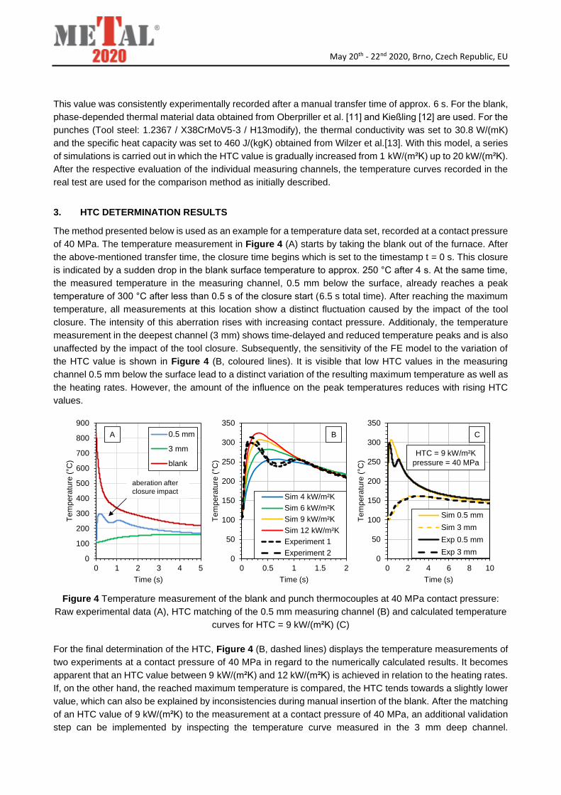
3. HTC DETERMINATION RESULTS
The method presented below is used as an example for a temperature data set, recorded at a contact pressure
of 40 MPa. The temperature measurement in Figure 4 (A) starts by taking the blank out of the furnace. After
the above-mentioned transfer time, the closure time begins which is set to the timestamp t = 0 s. This closure
is indicated by a sudden drop in the blank surface temperature to approx. 250 °C after 4 s. At the same time,
the measured temperature in the measuring channel, 0.5 mm below the surface, already reaches a peak
temperature of 300 °C after less than 0.5 s of the closure start (6.5 s total time). After reaching the maximum
temperature, all measurements at this location show a distinct fluctuation caused by the impact of the tool
closure. The intensity of this aberration rises with increasing contact pressure. Additionaly, the temperature
measurement in the deepest channel (3 mm) shows time-delayed and reduced temperature peaks and is also
unaffected by the impact of the tool closure. Subsequently, the sensitivity of the FE model to the variation of
the HTC value is shown in Figure 4 (B, coloured lines). It is visible that low HTC values in the measuring
channel 0.5 mm below the surface lead to a distinct variation of the resulting maximum temperature as well as
the heating rates. However, the amount of the influence on the peak temperatures reduces with rising HTC
values.
Figure 4 Temperature measurement of the blank and punch thermocouples at 40 MPa contact pressure:
Raw experimental data (A), HTC matching of the 0.5 mm measuring channel (B) and calculated temperature
curves for HTC = 9 kW/(m²K) (C)
For the final determination of the HTC, Figure 4 (B, dashed lines) displays the temperature measurements of
two experiments at a contact pressure of 40 MPa in regard to the numerically calculated results. It becomes
apparent that an HTC value between 9 kW/(m²K) and 12 kW/(m²K) is achieved in relation to the heating rates.
If, on the other hand, the reached maximum temperature is compared, the HTC tends towards a slightly lower
value, which can also be explained by inconsistencies during manual insertion of the blank. After the matching
of an HTC value of 9 kW/(m²K) to the measurement at a contact pressure of 40 MPa, an additional validation
step can be implemented by inspecting the temperature curve measured in the 3 mm deep channel.
0
50
100
150
200
250
300
350
0 0.5 1 1.5 2
Te
mp
era
ture
( C
)
Time (s)
Sim 4 kW/m²K
Sim 6 kW/m²K
Sim 9 kW/m²K
Sim 12 kW/m²K
Experiment 1
Experiment 20
50
100
150
200
250
300
350
0 2 4 6 8 10
Te
mp
era
ture
( C
)
Time (s)
Sim 0.5 mm
Sim 3 mm
Exp 0.5 mm
Exp 3 mm
B C
0
100
200
300
400
500
600
700
800
900
0 1 2 3 4 5
Te
mp
era
ture
( C
)
Time (s)
0.5 mm
3 mm
blank
aberation after
closure impact
A
HTC = 9 kW/m²K
pressure = 40 MPa

May 20th - 22nd 2020, Brno, Czech Republic, EU
Figure 4 (C) shows a comparison between the experimentally measured temperature curves over a longer
period of time and the numerically generated data. While a good agreement of the data can be seen in general,
especially the agreement of the 3 mm sub surface measuring channel confirms the material data of the punch
in respect for the thermal conductivity. Subsequently, this procedure was used to investigate the influence of
contact pressure in a range from 5 MPa to 80 MPa. The maximum recorded temperature averaged values are
shown in Figure 5 (A) in respect to the left y-axis. While there is a strong relationship between the contact
pressure and the temperature reading in the 0.5 mm sub surface measuring channel, the influence on the 3
mm sub surface measuring channel is comparatively low. Up to a contact pressure of 30 MPa, the maximum
temperature recorded in the 0.5 mm channel rises linearly up to 275 °C. After that, a jump in the average
temperatures can be noted. Because of the evidently higher standard deviation of the measurement at 40 MPa,
an overestimation has to be assumed. Because the measurements for this work were started at this pressure
level with a freshly machined tool surface first, it can be concluded that alteration effect due to growing oxide
scale on the tool surface could be the reason for the comparatively high measurement inaccuracy at this
pressure level. Since the standard deviation at the other pressure levels is much lower, the alteration of the
tool surface is negligible after the first measurements. The temperature measurement at a contact pressure of
80 MPa exceeds the process relevance of hot stamping, but illustrates that the temperatures in the punch are
reaching a saturation value. The HTC values determined with the described matching method are presented
in Figure 5 (A) plotted on the right y-axis. The pressure behaviour of the HTC is consecutively comparable to
the temperature findings. Furthermore, the HTC values are compared to the results in the literature quoted in
this study (Figure 5, B). All studies show an agreement in a rising HTC value over the contact pressure. Since
all studies are based on a non-standardised experimental method and data evaluation, the occurring deviations
are rated as comparatively low. The determination method presented in this paper can therefore be
recommended for process simulations with a distinct focus on the appearing tool surface temperatures with
the emphasis on a high contact pressure range.
Figure 5 Maximum tool temperatures in regard to the contact pressure in combination with determined HTC
values (A) and Comparison with literature data (B)
4. CONCLUSION
For the quenching stage of a hot-stamping process, a practical method for obtaining heat transfer coefficients
is presented. By designing a divisible stamping tool, welded thermocouples can be applied in measuring
channels with defined spacing from the surface providing a verifiable measuring location and a fast measuring
response time. Subsequently, a suitable FE-model is built up to map HTC values to specific pressure values
with an iterative comparison method of the temperature values. Because of the specimen dimension in relation
to the force potential of the testing machine, pressure ranges of the HTC in the literature could be extended.
0
2
4
6
8
10
0 10 20 30 40 50 60 70 80 90
HT
C (
kW
/m²K
)
Contact pressure (MPa)
This study
Merklein et al., 2009 [30]
Caron et al., 2014 [31]
Gu et al., 2016 [35]0
2
4
6
8
10
50
100
150
200
250
300
350
0 10 20 30 40 50 60 70 80 90
HT
C (
kW
/m²K
)
Maxim
um
T
ool T
em
pera
ture
( C
)
Contact pressure (MPa)
A B
8
9
[14]
Tmax 0.5 mm
Tmax 3.0 mm
HTC

May 20th - 22nd 2020, Brno, Czech Republic, EU
While this process window extension may not be relevant for common hot-stamping operations, it presents a
valuable addition when special hot-stamping related operations are considered such as adding an additional
joining step as presented by Stockburger et al. [15].
ACKNOWLEDGEMENTS
The authors gratefully acknowledge the support the German Federation of Industrial Research
Associations (AiF) within the project 19518 N for this research work.
REFERENCES
[1] TURETTA, A., BRUSCHI, S., GHIOTTI, A. Investigation of 22MnB5 formability in hot stamping operations.
Journal of Materials Processing Technology.2006, vol. 177, no. 1 - 3, pp. 396 - 400.
[2] BEHRENS, B.-A., BACH, F.-W., DIEKAMP, M., HÜBNER, S., NÜRNBERGER, F., SCHRÖDTER, J., WOLF, L.,
MORITZ, J. Process Time Reduction of Hot Stamping by Means of Early Extraction from the Press, In 4th
International Conference on Hot Sheet Metal Forming of High-Performance Steel. Luleå: LU Press, 2013, pp. 259
- 266.
[3] CARON, E., DAUN, K.J., WELLS, M.A. Experimental characterisation of heat transfer coefficients during hot
forming die quenching of boron steel. Metall. Mater. Trans. Vol. 44B, 2013, pp. 332 - 343.
[4] MORI, K., BARIANI, P.F., BEHRENS, B.-A., BROSIUS, A., BRUSCHI, S., MAENO, T., MERKLEIN, M.,
YANAGIMOTO, J. Hot stamping of ultra-high strength steel parts. CIRP Annals - Manufacturing Technology.
2017, vol. 66, no. 2, pp. 755 - 777.
[5] POLOZINE, A., SCHAEFFER, L. Influence of the inaccuracy of thermal contact conductance coefficient on the
weighted-mean temperature calculated for a forged blank. J. Mater. Process. Technol. 2008, vol. 195, pp. 260 –
266.
[6] ALTAN, T., SEMIATIN, S.L., COLLINGS, E.W., WOOD, V.E. Determination of the Interface Heat Transfer
Coefficient for Non-Isothermal Bulk-Forming Proceesses. Journal of Engineering for Industry. 1987, vol. 109, pp.
1-25.
[7] MALINOWSKI, Z., LENARD, J.G., DAVIES, M.E. A study of the heat-transfer coefficient as a function of
temperature and pressure. Journal of Materials Processing Technologies. 1994, vol. 41, pp. 18-24.
[8] MERKLEIN, M., LECHLER, J., STOEHR, T. Investigations on the thermal behavior of ultra-high strength boron
manganese steels within hot stamping. Int. J. Mater. Form., 2009, vol. 2, Suppl. 1, pp. 259 - 262.
[9] CARON, E., DAUN, K.J., WELLS, M.A. Experimental heat transfer coefficient measurements during hot forming
die quenching of boron steel at high temperatures. International Journal of Heat and Mass Transfer.2014, vol. 71,
pp. 396 - 404.
[10] Caron, E., Wells, M.A., Li, D. A Compensation Method for the Disturbance in the Temperature Field caused by
Subsurface Thermocouples. Metallurgical and Materials Tansactions, 2006, vol. 37B, pp. 245-252.
[11] OBERPRILLER, B., BURKHARDT, L., GRIESBACH, B. Benchmark 3 - Continuous Press Hardenin, Proc. of
Numisheet. 2008, no. 9, pp. 115 - 129.
[12] KIESSLING, R. Untersuchungen zu den werkstoffspezifischen Versagensmechanismen von Widerstandspunkt-
schweißungen unter Crash- und Ermüdungsbeanspruchung, Abschlußbericht, BMWi / AiF-Nr. 14.927 N.
[13] WILZER, J.J., WEBER, S., ESCHER, Ch., THEISEN, W. Material Requirements for Hot Stamping Tools using the
Example of Tool Steels X38CrMoV5-3, 30MoW33-7, and 60MoCrW28-8-4. HTM J. Heat Treatm. Mat. 2014, vol.
69, pp. 1-6.
[14] GU, Z.-W., LV, M.-M., LU, G.-H., XU, H., LI, X. Heat transfer coefficient evolution of boron steel during hot forming
die quenching. Materials Science and Technology. 2015, vol. 32, no. 2, pp. 173-180.
[15] BEHRENS, B-A., JÜTTNER, S., BRUNOTTE, K., ÖZKAYA, F., WOHNER, W. STOCKBURGER, E. Extension of
the Conventional Press Hardening Process by Local Material Influence to Improve Joining Ability. Procedia
Manufacturing, 2020, vol. 47, pp. 1345-1352.