Embed Size (px)
Citation preview

PRACTICALRADIATIONTECHNICALMANUAL
WORKPLACE MONITORING FOR RADIATION AND CONTAMINATION

WORKPLACE MONITORING FOR RADIATION AND CONTAMINATION

PRACTICAL RADIATION TECHNICAL MANUAL
WORKPLACE MONITORING
FOR RADIATION AND CONTAMINATION
INTERNATIONAL ATOMIC ENERGY AGENCYVIENNA, 2004

WORKPLACE MONITORINGFOR RADIATION AND CONTAMINATION
IAEA, VIENNA, 2004
IAEA-PRTM-1 (Rev. 1)
© IAEA, 2004
Permission to reproduce or translate the informationin this publication may be obtained by writing to
the International Atomic Energy Agency,Wagramer Strasse 5, P.O. Box 100, A-1400 Vienna, Austria.
Printed by the IAEA in ViennaApril 2004

FOREWORD
Occupational exposure to ionizing radiation can occur in a range of industries,such as mining and milling; medical institutions; educational and researchestablishments; and nuclear fuel facilities. Adequate radiation protection ofworkers is essential for the safe and acceptable use of radiation, radioactivematerials and nuclear energy.
Guidance on meeting the requirements for occupational protection in accor-dance with the Basic Safety Standards for Protection against IonizingRadiation and for the Safety of Radiation Sources (IAEA Safety SeriesNo. 115) is provided in three interrelated Safety Guides (IAEA SafetyStandards Series No. RS-G-1.1, 1.2 and 1.3) covering the general aspects ofoccupational radiation protection as well as the assessment of occupationalexposure. These Safety Guides are in turn supplemented by Safety Reportsproviding practical information and technical details for a wide range ofpurposes, from methods for assessing intakes of radionuclides to optimizationof radiation protection in the control of occupational exposure.
Occupationally exposed workers need to have a basic awareness and under-standing of the risks posed by exposure to radiation and the measures formanaging these risks. To address this need, two series of publications, thePractical Radiation Safety Manuals (PRSMs) and the Practical RadiationTechnical Manuals (PRTMs) were initiated in the 1990s. The PRSMs coverdifferent fields of application and are aimed primarily at persons handling ra-diation sources on a daily basis. The PRTMs complement this series anddescribe a method or an issue related to different fields of application,primarily aiming at assisting persons who have a responsibility to provide thenecessary education and training locally in the workplace.
The value of these two series of publications was confirmed by a group ofexperts, including representatives of the International Labour Organization, in2000. The need for training the workers, to enable them to take part in deci-sions and their implementation in the workplace, was emphasized by the

International Conference on Occupational Radiation Protection, held inGeneva, Switzerland in 2002.
This Practical Radiation Technical Manual, which incorporates revisionsdrawn up in 2002, was originally developed following recommendations of anAdvisory Group Meeting on Radiation Protection Technical Guides, held from23 to 27 April 1990, in Vienna, Austria. The format and contents of the draftwere agreed by a committee of experts comprising Deping Li (China), A.V.Bilbao (Cuba), P. Bory (France), F.E. Stieve (Federal Republic of Germany),G.J. Koteles (Hungary), Mr. S. Venkatesan (India), M.S. Sohrabi (Iran), S.K.Wanguru (Kenya), R. Wheelton (United Kingdom), C. Jones (USA), V. Kozlov(USSR), G. Severuikhin (USSR), H.G. Menzel and D. Teunen (representingCEC), G.H. Coppee (representing ILO) and R.V. Griffith (IAEA). Major contri-butions were made by Mr. R. Wheelton, United Kingdom, who also contributedto the present revision, undertaken by the Radiation Monitoring andProtection Services Section, IAEA.

CONTENTS
1–5 Types of radiation measuring instruments
6 Basic instrument components
7–13 Gas filled detector instruments
14–16 Scintillation detector instruments
17–18 Solid state detector instruments
19–20 Neutron monitoring instruments
21–23 Use of dose rate monitoring instruments
24–26 Use of surface contamination monitoring techniques
27 Special surface contamination monitoring techniques
28 The measurement of airborne contamination
29 Criteria for the selection of monitoring instruments
30 Expertise in radiation monitoring
31 Bibliography

IAEA PRACTICAL RADIATION TECHNICAL MANUAL
WORKPLACE MONITORING FOR RADIATION AND CONTAMINATION
This Practical Radiation Technical Manual is one of a series which has beendesigned to provide guidance on radiological protection for employers,Radiation Protection Officers, managers and other technically competentpersons who have a responsibility to ensure the safety of employees workingwith ionizing radiation. The Manual may be used together with the appropriateIAEA Practical Radiation Safety Manuals to provide adequate training,instruction or information for all employees engaged in work with ionizingradiations.
1

WORKPLACE MONITORING FOR RADIATION AND CONTAMINATION
Introduction
Ionizing radiations cannot be seen, felt or sensed by the human body in anyway but excessive exposure to them may have adverse health effects.Radiation measuring instruments are needed in order to detect the presenceof such radiations and avoid excessive exposure. The use of appropriate andefficient instruments enables exposures to be controlled and the dosesreceived to be kept as low as reasonably achievable.
This Manual explains the basic terminology associated with such measuringinstruments and describes the principal types, their construction and typicalapplications in the workplace.
It is important to ensure not only that monitoring is carried out where there isa potential radiation exposure but also that the monitoring instrument isappropriate to the task and that the user places correct interpretations on theresults obtained.
The Manual will be of most benefit if it forms part of more comprehensivetraining or is supplemented by the advice of a qualified expert in radiationprotection. Some of the instrument tests and calibrations described in thisManual require the services of a qualified expert.
3

1. TYPES OF RADIATION MEASURING INSTRUMENTS
Radiation measuring instruments are needed to detect and quantify two typesof exposure: external exposure to penetrating radiations emitted by sourcesoutside the human body; and internal exposure which is associated withradioactive materials which are in a form capable of entering and interactingwith the human body.
Four basic types of radiation measuring instrument may be used in the work-place:
(A) Dose rate meters used to measure the external exposure.(B) Dosimeters which indicate the cumulative external exposure.(C) Surface contamination meters which indicate the potential internal expo-
sure when a radioactive substance is distributed over a surface.(D) Airborne contamination meters and gas monitors which indicate the
internal exposure when a radioactive substance is distributed within anatmosphere.
4

5
Workplace radiation monitoring instruments.
Instrument types include:dose rate meters, dosimeters, surface contamination meters,
and airborne contamination meters and gas monitors.

2. DOSE RATE METERS
A dose rate meter absorbs energy from penetrating radiation. A suitable andefficient instrument which is matched to the specific task should be capableof providing direct readings of the dose equivalent rate in microsieverts perhour (mSv/h or mSv·h–1). A smaller number of instruments indicate theabsorbed dose rate in micrograys per hour (mGy·h–1). These usually respondonly to X, gamma and/or beta radiations. Specialized instruments are neces-sary to measure neutron dose equivalent rates.
Older units of dose rate — millirem per hour (mrem/h), millirad per hour(mrad/h) and milliroentgen per hour (mR/h) — are still displayed on someinstruments (10 mSv·h–1 is equivalent to 1 mrem/h).
Dose rate meters may not be able to provide an accurate response to rapidlychanging or pulsed radiation fields. Integrating dose rate meters and dosi-meters are more appropriate in such circumstances.
6

7
A dose rate meter measures external hazards in units of
dose equivalent rate.
Dose rate meters provide direct measurements of external exposure.

3. DOSIMETERS
A dosimeter measures the cumulative energy absorbed as a consequence ofexposure to ionizing radiation.
Personal dosimeters must be worn by radiation workers to measure their ra-diation exposure. Passive dosimeters routinely monitor cumulative dosesresulting from an external exposure. Active dosimeters provide an immediatereading of the dose in microsieverts (mSv) and may also provide an immediatealarm signal when the measured dose approaches a value pre-set by themanufacturer or user.
Integrating dose rate meters and dosimeters are used to assess an externalexposure which is rapidly changing, for example: (a) a task of short durationhas to be carried out in the presence of high dose rates; (b) the source (e.g.,an X ray machine) emits radiation pulses of short duration.
Further information on dosimeters is provided in the Practical RadiationTechnical Manual on Individual Monitoring.
8

9
Personal dosimeters and integrating dose rate meters measure
the dose equivalent due to an external hazard that is rapidly changing.
Dosimeters provide a measurement of cumulative exposure to radiation.
4. SURFACE CONTAMINATION METERS
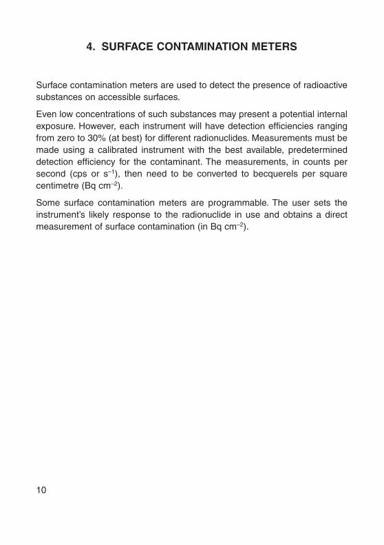
Surface contamination meters are used to detect the presence of radioactivesubstances on accessible surfaces.
Even low concentrations of such substances may present a potential internalexposure. However, each instrument will have detection efficiencies rangingfrom zero to 30% (at best) for different radionuclides. Measurements must bemade using a calibrated instrument with the best available, predetermineddetection efficiency for the contaminant. The measurements, in counts persecond (cps or s–1), then need to be converted to becquerels per squarecentimetre (Bq cm–2).
Some surface contamination meters are programmable. The user sets theinstrument’s likely response to the radionuclide in use and obtains a directmeasurement of surface contamination (in Bq cm–2).
10

11
A surface contamination meter indicates the internal hazard.
Surface contamination meters are used to detect and measure radioactive substances on surfaces.

5. AIRBORNE CONTAMINATION METERS AND GAS MONITORS
Airborne contamination meters are used to detect radioactive aerosols whichmay be present within the atmosphere. These may be dispersion aerosols(dusts), condensation aerosols (smoke) or liquid aerosols (mists). The instru-ments used normally draw potentially contaminated air at a constant ratethrough a filter. The instrument may then be capable of detecting the accu-mulated radioactive material on the filter or the filter may need to be assessedelsewhere.
Gas monitors contain a radiation detector and continuously sample the airdirectly to measure the presence of radioactive gases.
The contaminant must be identified in order to determine the activity concen-tration in becquerels per cubic metre (Bq·m–3).
Airborne contamination meters and gas monitors may be used to assessairborne contamination in the workplace. Personal air samplers (PAS) areused to monitor the often more significant hazard within the breathing zone ofan individual worker. These instruments are often passive devices which donot provide immediate results. They only provide retrospective assessmentsof the working conditions but may also provide estimates of intakes.
Instruments that are capable of detecting the radionuclide may be used asactive devices to provide an alarm signal when the airborne radioactivityconcentration reaches a pre-set value.
12

13
Personal and static samplers and gas monitors are used
to monitor airborne contamination.
Airborne contamination meters are used to detect and measure particulate radioactivity in the atmosphere.
Gas monitors are used to detect and measure radioactive gases in the atmosphere.

6. BASIC INSTRUMENT COMPONENTS
Commercially available radiation detection instruments are often described andprocured on the basis of their essential components. The key components are:
(A) The detector. The detector contains a medium which absorbs radiationenergy and converts it into a signal. Electrical charge usually forms the signal. Common detectors include:
Gas filled detectors;Ionization chambers;Proportional counters;Geiger-Müller counters;Scintillation counters;Solid state detectors.
(B) The amplifier. The signals from a detector may need to be electronicallyamplified.
(C) The processor. According to the type of instrument, the processor maybe a device to measure the size or number of signals produced by thedetector. It may also translate the quantity measured into appropriateradiological units.
(D) The display. The measurement is presented either in a digital format oras an analogue display showing a pointer on a graduated scale.
(R) The radiation. Ionizing radiations (alpha or beta particles, gamma orX rays, or neutrons) which enter the detector need to be absorbed to bedetected.
(I) Ionization. The process in which the detector medium absorbs radiationenergy.
14

15
Radiation monitoring instrument components.
All types of instruments are constructed using basic instrument components.

7. IONIZATION CHAMBERS AS GAS FILLED DETECTORS
Ionization chambers, like proportional counters and Geiger-Müller counters,are gas filled detectors. The essential components of these detectors are:
A — a container or detector wall which encloses the gas.The material usedstrongly influences the instrument’s performance and use.
E1,2 — electrodes (a positive anode and a negative cathode) physically sepa-rated and across which a fixed potential difference (voltage) ismaintained.
P — a power supply (battery).D — a display.
Ionization counters can operate with different gas fillings and gas pressuresbut often air is used at atmospheric pressure and temperature. When the gasabsorbs radiation energy and is ionized, the number of ions created is propor-tional to the energy absorbed. The ions move under the influence of the elec-trode potential difference and are collected by the electrodes to form a smallelectrical current which can be measured by the processor.
16

17
Principal components of an ionization chamber.
Ionization chambers, proportional counters and Geiger-Müller counters are gas filled detectors operating on the fact that radiation causes ionization
in the gas filling.

8. PROPORTIONAL COUNTERS AND GAS AMPLIFICATION
Proportional counters typically contain a mixture of inert and organic gasfillings, but other fillings may be used to form special detectors. For example,incorporating boron trifluoride (BF3) allows the detection of neutrons (seeSection 19).
The detectors may operate at elevated gas pressures to provide higher detec-tion efficiencies for X, gamma and beta radiations. The high voltages appliedalso increase their sensitivity to low dose rates.
The higher voltages cause the ions, which are created by ionizing radiations,to accelerate as they approach the electrodes. The fast moving negative ions
in turn cause further ionization. This is called gas amplification. Thenumber of ions collected by the electrode will be proportional to the numberproduced by the radiation. The detector’s output is a pulse of charge when the ions are collected on the electrode. The size of this pulse is proportionalto the energy absorbed by the detector.
18

19
Gas amplification occurs in both proportional and Geiger-Müller counters.
Proportional counters and Geiger-Müller counters use gas amplification to increase detector outputs over the primary ionizations.

9. GEIGER-MÜLLER COUNTERS AND DETECTOR OUTPUT
Geiger-Müller counters (also called GM and Geigers) contain a low pressureinert gas and traces of an organic or halogen gas called the quenching agent.
The potential difference between a GM’s electrodes is high and sufficient tocause an almost complete ionization of the detector gas from the gas ampli-fication of a single primary ionization. A momentary reduction of the voltagethen allows the detector’s recovery.
The graph illustrates the relative response of gas filled detectors to a singleionizing particle. The number of ions collected (n) is plotted against thedetector voltage (V). The detector regions are indicated.
A — ionization chambers. Above a minimum voltage the few primary ionsdo not recombine and are collected.
B — proportional counters. The detector’s response increases withincreasing ionization.
C — Geiger-Müller counters. The avalanche of ions collected is indepen-dent of the primary ionization.
A GM’s output differs from that of other gas filled detectors. Pulses of elec-trical charge result at a count rate which is related to the radiation fluence(particle intensity) and independent of the energy absorbed in the detector.
20

21
Typical outputs of gas filled detectors in response to single primary ionizations
from different types of radiation.
Gas filled detectors need to operate at the appropriate voltages in order to function properly.

10. PRACTICAL IONIZATION CHAMBER INSTRUMENTS
Ionization chambers are used to manufacture accurate dose rate meters aswell as integrating dose rate meters. A typical construction is illustrated:
A — the cylindrical detector wall serves as the cathode (negative elec-trode) and is normally made of air-equivalent, carbon coated plastic oraluminium.
B — the axial anode (positive electrode).C — beta window made of thin foil (3–7 mg·cm–2).D — protective buildup cap (200–300 mg·cm–3) made of toughened plastic
or aluminium.
The buildup cap is used to improve the detection efficiency when measuringhigh energy photon radiations. It is removed when measuring dose rates dueto low energy photons (10 to 100 keV) and beta radiations.
Detector volumes of a few hundred cubic centimetres are needed to measureexposures in nanocoulombs per hour (nC·h–1). The processor converts theseunits to the appropriate radiation dose rates from about 10 µSv·h–1. Ambientvariations of temperature, humidity and air pressure will affect the detectorand should be corrected as appropriate. Detectors may be screened againstextraneous radiofrequency interference.
22

23
A dose rate meter.
Practical ionization chambers provide accurate measurement of dose rate.

11. PRACTICAL PROPORTIONAL COUNTERS
Portable dose and dose rate meters which incorporate proportional countersare uncommon in the workplace. Although proportional counters capable ofmeasuring low dose rates are smaller than equivalent ionization chambers,their need for a highly stable power and gas supplies and other technicalrequirements disadvantage them. The proportional counter’s superiorfeatures are best used in the form of surface contamination meters which maycontain detectors as large as 1500 cm2.
Compared with Geiger counters, proportional counters have a betterresponse to low energy photons and a sensitivity to beta radiations. However,Geiger instruments are less costly for measuring dose rates due to pene-trating radiations.
Proportional counters are of most use in the laboratory. The detector’s appli-cations include spectrometry, neutron detection, discrimination betweenionizing particles (e.g., electrons and protons) and absolute measurements ofthe activity of beta emitters.
24

25
A large area proportional counter incorporated in
a floor contamination meter.
Proportional counters are used to measure dose rate, airborne radioactivity and surface contamination.

12. PRACTICAL GEIGER-MÜLLER COUNTERS
Geiger-Müller counters are mass produced in a range of shapes, sizes, sensi-tivities and detection geometries. The detector requires only a moderatelystable voltage, a simple amplifier and other inexpensive components,including a ratemeter (C), to construct a useful instrument.
Common forms include:
(A) The Geiger tube. A cylindrical tube (often of glass about 30 mg·cm–2
thick) contains a tubular cathode and an axial wire anode. As a sidewindow detector, the tube is enclosed within a metal shield which has a shutter. The shield protects the tube and provides a means to discrim-inate between penetrating and non-penetrating radiations.
(B) The end window Geiger tube. A cylindrical thin metal body forms thecathode which is sealed at one end by a thin window of about2 mg·cm–2. Alpha, beta and photon radiations are detected through the window but with poor detection efficiencies.
The pulsed output of Geiger counters is often to form an audible indication ofthe detected count rate. Such instruments rapidly respond to varying doserates. The less sophisticated Geiger counters can be ‘saturated’ by an excep-tionally high dose rate. In this potentially hazardous situation, these instru-ments become paralysed and cease to function. Special circuits may ensurethat a full scale reading is maintained under these circumstances.
26

27
Geiger counter probes and a ratemeter — useful as search instruments
and surface contamination meters.
Geiger-Müller counters are the most commonly commercially used instruments to measure dose rate, dose and surface contamination.

13. COMPENSATED GEIGER DOSE RATE METERS
The Geiger counter has a high sensitivity but is very dependent upon theenergy of photon radiations. The graph illustrates the relative response (R) ofa typical Geiger counter plotted against photon energy (E). At about 60 keVthe response, shown by the solid line in the figure, reaches a maximum whichmay be thirty times higher than the detector’s response at other radiationenergies.
In order to more accurately measure dose rates, a normalized response at 1.0is required, as represented by the dotted line. The detector’s poor energyresponse may be corrected by adding a compensation sheath. Thin layers ofmetal are constructed around the Geiger tube to attenuate the lower photonenergies, where the fluence per unit dose rate is high, to a higher degree thanthe higher energies. The modified or compensated response, shown as adashed line on the graph, may be independent of energy within ± 20% overthe range 50 keV to 1.25 MeV. Compensation sheaths also influence aninstrument’s directional (polar) response and prevent beta and very lowenergy photon radiations from reaching the Geiger tube.
28

29
Energy response characteristics typical of Geiger counters
and compensated Geiger counters.
Geiger-Müller counters can be compensated to provide a uniform response as dose rate meters.

14. SCINTILLATION COUNTERS
The essential components of a scintillation counter are:
S — scintillator. A substance (a phosphor) contained within an opaquematerial. Ionizing radiations interact with the scintillator, which almostimmediately converts some of the absorbed energy into a flash oflight.
L — light guide transfers the scintillation to the photocathode (C) of thephotomultiplier (M).
C — photocathode is a translucent, light sensitive coating of material (e.g.,antimony-caesium) on the photomultiplier window. When it absorbslight it emits a proportionate number of electrons.
M — photomultiplier tube contains electrodes called dynodes. A succes-sively in-creased potential difference (about 2000 V overall) drawselectrons to each dynode in turn. The number of electrons increasesat each dynode. The number of electrons is amplified by about onemillion.
Phosphors include solid organic materials such as anthracene and stilbene,liquid solutions of organic materials (liquid scintillants), solid solutions oforganic materials (plastic scintillants) and activated inorganic crystals such assodium iodide and caesium iodide which are activated by trace quantities ofthalium (NaI(Tl) and CsI(Tl)).
30

31
Principal components of a scintillation counter.
Scintillation counters contain a phosphor and a photomultiplier.

15. PRACTICAL BULK SCINTILLATION COUNTER INSTRUMENTS
The very wide range of phosphors in a multitude of sizes, geometries andsensitivities can be combined with photomultipliers ranging from 6 to 300 mmin diameter to manufacture a large variety of scintillation counter instruments.
Plastic and inorganic phosphors with densities close to 1000 times greaterthan those of gas filled detectors form gamma and X ray detectors of veryhigh sensitivity. Crystals of up to 40 cm in diameter and 40 cm in thicknessexist but crystals of a diameter between 1 cm and 7.5 cm and of a thicknessbetween 1 cm and 7.5 cm are regularly used. For radiation that is incidentperpendicular to a 2.5 cm thick NaI(Tl) crystal, the detection efficiency isabout 37% for 1 MeV photons, rising to almost 100% at energies below200 keV.
For detectors of sufficient size, the scintillations will be proportional to theenergy of the incident photons, allowing them to be used for gamma spec-trometry. The scintillation rate is proportional to the radiation fluence and notthe dose rate, but scintillation dose rate meters, that operate over limitedenergy ranges, can indicate low and high dose rates even at low photon ener-gies. However, the photomultiplier’s demand for a stable voltage supply andhigh component costs make these instruments comparatively expensive.Their bulk, weight and vulnerability to shock also limit their usefulness.However, portable instruments are now available which provide spectrometryas well as dosimetry.
Lithium iodide activated by europium (LiI(Eu)) and silver activated zincsulphide (ZnS(Ag)) in a boron loaded plastic scintillator are used for neutrondetection.
32

33
Penetrating radiation scintillation counter probes.
Scintillation counter instruments can be designed to be highly sensitive to gamma and neutron radiations.

16. PRACTICAL SCINTILLATION COUNTER CONTAMINATION MONITORS
Highly sensitive surface contamination probes incorporate a range of phos-phor arrangements. In addition to the gamma phosphors described, otherexamples include: zinc sulphide (ZnS(Ag)) powder coatings (5–10 mg·cm–2)on glass or plastic substrates or coated directly onto the photomultiplierwindow for detecting alpha and other heavy particles; caesium iodide (CsI(Tl))that is thinly machined (0.25 mm) and that may be bent into various shapes;and plastic phosphors in thin sheets or powders fixed to a glass base for betadetection.
Probes (A and B in the figure) and their associated ratemeters (C) tend not tobe robust. Photomultipliers are sensitive to shock damage and are affected bylocalized magnetic fields. Even minor damage to the thin foil through whichradiation enters the detector allows ambient light to enter and swamp thephotomultiplier. Cables connecting ratemeters and probes are also a commonproblem.
Very low energy beta emitters (for example 3H) can be dissolved in liquidphosphors in order to be detected.
34

35
Non-penetrating radiation scintillation counter probes and ratemeter.
Scintillation counter instruments can be designed to be highly sensitive to alpha and beta radiations.

17. SOLID STATE DETECTORS
Solid state detectors utilize semiconductor materials. Intrinsic semiconductorsare of very high purity and extrinsic semiconductors are formed by addingtrace quantities (impurities) such as phosphorus (P) and lithium (Li) to mate-rials such as germanium (Ge) and silicon (Si). There are two groups of detec-tors: junction detectors and bulk conductivity detectors.
Junction detectors are of either the diffused junction or the surface barriertype: an impurity is either diffused into, or spontaneously oxidized onto, aprepared surface of intrinsic material to change a layer of ‘p-type’ semi-conductor from or to ‘n-type’. When a voltage (reverse bias) is applied to thesurface barrier detector, as shown, it behaves like a solid ionization chamber.
A — very thin metal (gold) electrode.P — thin layer of p-type semiconductor.D — depletion region, 3–10 mm thick formed by the voltage, is free of
charge in the absence of ionizing radiations.N — n-type semiconductor.B — thin metal electrode which provides a positive potential at the n-type
semiconductor.
Bulk conductivity detectors are formed from intrinsic semiconductors of veryhigh bulk resistivity (for example CdS and CdSe). They also operate likeionization counters but with a higher density than gases and a ten-fold greaterionization per unit absorbed dose. Further amplification by the detectorcreates outputs of about one microampere at 10 mSv·h–1.
36

37
Principles of surface barrier solid state counter —
shown enlarged and in section.
Solid state counters contain semiconductor devices.

18. PRACTICAL SOLID STATE DETECTORS
The main applications for semiconductor detectors are in the laboratory forthe spectrometry of both heavy charged (alpha) particle and gamma radia-tions. However, energy compensated PIN diodes and special photodiodes areunder development as pocket electronic (active) dosimeters.
Specially combined thin and thick detectors provide the means to identifycharged particles. These are used to monitor for plutonium in air, discrimi-nating against alpha particles arising from natural radioactivity, and for moni-toring for radon daughter products in air. Their small physical size and insen-sitivity to gamma radiation have found novel applications: inside nuclear fuelflasks monitoring for alpha contamination and checking sealed radiumsources for leakage.
Bulk conductivity detectors can measure high dose rates but with minute-longresponse times. A Ge(Li) detector operated at –170°C is capable of a veryhigh gamma resolution of 0.5%. The temperature dependence and high costadd to their impracticality.
38

39
A miniature, personal, electronic, integrating dose rate meter.
Solid state counters are used in special applications, some of which are still under development.

19. NEUTRON DETECTION
As chargeless particles, neutrons are detected only by their interactions withatomic nuclei. Detector nuclei may react to neutrons in three specific ways:some disintegrate, emitting secondary ionizing radiations; others recoil andcause ionization; and certain nuclei are activated.
The interaction of thermal neutrons with boron-10 (10B) is used as the basisfor a number of detectors. A 10B nucleus which absorbs a thermal neutronundergoes a neutron-alpha (n,a) reaction, emitting an alpha particle andforming 7Li. Similarly, after an (n,a) reaction 6Li forms 3He. Detectors alsoemploy the neutron-proton (n,p) reaction of 3He and (n,fission) reactionsutilizing fissionable materials. The neutron-gamma (n,g) reactions in cadmiumand rhodium are used by photographic detectors.
The interaction of fast neutrons in hydrogenous materials produces recoilprotons which are readily detected in photographic emulsion, gas filled, scin-tillation and solid state detectors.
Radioactivity is induced in indium, gold and sulphur as a function of the neutron dose. Suitably calibrated detectors may be used to measure the activity.
40

41
Nuclear interactions used in the detection of neutrons.
Neutrons are detected by interaction with certain target nuclei.

20. PRACTICAL NEUTRON MONITORING INSTRUMENTS
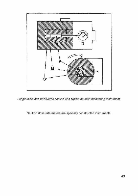
Air filled ionization chambers with thin internal coatings of boron are effectivebut proportional counters which contain either boron trifluoride (BF3) orhelium-3 (3He) gas form more sensitive detectors. A typical instrumentconstruction is shown:
D — display.P — proportional counter incorporating BF3 or 3He.M — cylindrical or spherical polyethylene moderator to thermalize incident
fast neutrons for detection.S — perforated cadmium or boron plastic sheath which modifies the energy
response according to neutron quality factors to enable the directmeasurement of dose equivalent rates.
Gas filled proton recoil detectors are lined with polythene and may also incor-porate ethylene gas.
Scintillation detectors for thermal neutrons may incorporate such phosphorsas LiI(Eu) or ZnS(Ag) mounted on a boron loaded plastic. Fast neutrons maybe detected directly using organic scintillators or ZnS(Ag) in clear plastic; orthey may be moderated and then detected using a boron loaded plastic andZnS(Ag) phosphor.
Semiconductor detectors utilize (n,a), (n,p) or recoil proton reactions butunpreventable recoil reactions damage the semiconductor.
42
43
Longitudinal and transverse section of a typical neutron monitoring instrument.
Neutron dose rate meters are specially constructed instruments.

21. TESTING DOSE RATE METERS
Most dose rate meters are ‘type tested’ by manufacturers and independentlaboratories. The results may be found in the technical literature. In addition tothe instrument’s description, its directional and energy response as well asaccuracy may be reported over the appropriate dose rate and energy ranges.
Each instrument must be tested before first use, at regular intervals (annually)and after any repair which may have affected the instrument’s performance.These tests are conducted by qualified experts using calibrated radiationsources. The objectives are:
(i) To check that the instrument operates efficiently and to its specification.In addition to its radiation response, the instrument’s electrical andmechanical features may also be tested.
(ii) To reveal the magnitude of any likely errors in the instrument’s measure-ments. The user may accept ± 20% errors but should correct knownerrors which fall outside these limits. Errors in excess of ± 50% suggestthat the instrument is unsuitable for the intended purpose. The linearityof response, interrange differences and overload protection may also beinvestigated.
The user of a dose rate meter should keep a certificate relating to the lastformal test or calibration and should carry out routine checks on the instru-ment. Some instruments have installed check sources but the regularmeasurement of a known dose rate serves the purpose. The battery conditionshould be checked each time the instrument is used.
44

45
Calibrated sources and the inverse square law are applied to
the testing of dose rate meters.
Dose rate meters must be formally tested and calibrated at appropriate intervals.

22. USE OF DOSE RATE METERS
The dose rate meter used should be suitable for the application. An incorrectchoice can lead to inaccurate or even erroneous assessments of the externalhazard.
The use of ionization chambers can result in narrow beams of radiation beingunderevaluated and even undetected because of their slow response. Anymeasurement requires the beam to exceed the detector’s size. As ‘searchinstruments’ faster responding, end window Geigers and scintillation countersare better used.
A buildup cap may be used as a ‘discriminator’ to shield an ionization counterand provide a rough indication of the type and energy of incident radiation.The technique is useful to identify bremsstrahlung arising from beta radiationapplications. Energy compensated instruments are only capable of detectingpenetrating radiations.
Dose rates are measured for various reasons: to control task related doses;to check on the adequacy of shielding for stored sources; for transportpurposes; and to ensure that all potential external exposures are identified.Measurements may be compared against appropriate reference levels, suchas: limits for different categories of transport package, and reference levels toclassify the workplace.
46

47
Dose rates are measured around a transport package.
Dose rate meters must be suitable for the intended application and used to determine external exposure in the workplace.

23. PROCEDURE FOR USING A DOSE RATE METER
Before attempting to make a radiation measurement it is essential for the userto be completely familiar with the features and controls of the instrument.The following procedure can then be used to measure external exposure.
(i) Check the test or calibration certificate. Confirm that the last formal testdate, test conditions and result are satisfactory. Check the last routinetest result.
(ii) Assess the radiation to be measured. Judge whether the instrument issuitable to obtain the measurement required.
(iii) Set the instrument’s parameters. Test the battery, adjust the detectorvoltage and set the zero as necessary.
(iv) Obtain the measurement. On multirange instruments, start on themaximum and then switch successively to lower ranges until an appro-priate reading is obtained. Check the range setting and note the reading.Repeat the measurement with and without a buildup cap or with abeta/gamma shutter open and closed. Check the stability of the readingsfor different orientations of the instrument.
(v) Assess the result. Decide whether there are any factors which haveinfluenced the result such as: small beam size; a non-isotropic or pulsingradiation field; temperature, humidity or air pressure effects; or inter-ference from radiofrequency or magnetic fields.
(vi) Apply correction factors. Multiply the reading by any relevant correctionor calibration factors.
(vii) Record the result. Decide whether the result is reasonable by compari-son with previous measurements or calculations. Keep a written recordof the conclusions.
48

49
It is important to understand the controls and the display of
a dose rate meter before attempting to use it.
The user of a dose rate meter must understand the instrument used and follow a procedure to obtain a meaningful measurement.

24. TESTING AND CALIBRATING SURFACE CONTAMINATION METERS
Each surface contamination meter is designed and type tested to measure a specific range of contaminants. Its response to contamination will dependupon:
(i) The type and energy of the radiation or, precisely, the radionuclide whichforms the contamination.
(ii) The instrument’s intrinsic detection efficiency for each radionuclide,which is determined by the detector’s characteristics, the window areaand thickness and the dimensions of any protective grille.
(iii) The detection geometry, including the detector’s dimensions, the natureof the contaminated surface and the detector-to-surface distance.
(iv) Inherent electrical noise, ageing or fault conditions in the instrument’scomponents.
Each instrument must be tested before first use, at regular intervals (annually)and after any repair which may have affected the instrument’s performance.These tests are conducted by qualified experts using calibrated, uniformlycontaminated plaques (P) with an active area of similar dimensions to thedetector (D). The radionuclide used must emit radiations similar to those ofpotential contaminants. The objectives are:
(i) To determine the operating voltage for each detector, especially inter-changeable probes. Other electrical and mechanical features may alsobe tested.
(ii) To obtain or confirm the detection efficiency (E counts per disintegration)of the instrument for each appropriate radionuclide. Using the detectionefficiency, a calibrated response can then be provided to the user toconvert readings (cps or s–1) to Bq·cm–2. The linearity of response andinterrange differences may also be investigated.
The instrument user should keep a certificate relating to the last formal testand should carry out routine checks on the instrument. Sources are availablefor this purpose which are sometimes attached to the instrument’s windowcover. The battery condition should be checked each time the instrument isused.
50

51
A surface contamination meter is tested against a calibrated source.
Surface contamination meters must be formally tested and calibrated at appropriate intervals.

25. USE OF A SURFACE CONTAMINATION METER
A suitable surface contamination meter should be available whereverunsealed radioactive substances such as liquids and powders are in use.However, care must be taken to avoid the instrument contacting potentiallycontaminated surfaces.
Instruments which comprise a ratemeter and probe provide versatility both inthe range of detectable radionuclides (using different probes) and the easewith which readings can be taken. The surfaces of the body, of protectiveclothing, of working areas (benches, floors, etc.), of plumbing and transportpackages are some of the surfaces that should be routinely monitored forspillages or contamination.
52
53
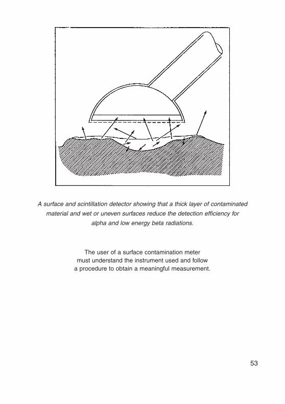
A surface and scintillation detector showing that a thick layer of contaminated
material and wet or uneven surfaces reduce the detection efficiency for
alpha and low energy beta radiations.
The user of a surface contamination meter must understand the instrument used and follow
a procedure to obtain a meaningful measurement.

26. PROCEDURE FOR USING A SURFACE CONTAMINATION METER
(i) Check the test or calibration certificate. Confirm that the last formal testdate, test conditions and result are satisfactory. Check the last routinetest result.
(ii) Assess the potential contaminant radionuclide. Judge whether theinstrument is suitable.
(iii) Set the instrument’s parameters. Test the battery, adjust the detectorvoltage and set the zero as necessary. Start multi-range instruments onthe minimum.
(iv) Obtain a background reading (s–1) at about 1 m from the contaminatedsurface.
(v) Obtain a reading from the contaminated surface. At a speed appropriateto the detector’s capabilities, scan the instrument or its probe over thesurface at a distance which avoids contact. Hold the detector at the cali-bration distance (about 0.5 cm) from the contamination to obtain thesurface reading.
(vi) Calculate the indicated total surface contamination. Subtract the back-ground from the surface reading. Then use the appropriate calibrationdata to convert the corrected measurement from a count rate to a valueof surface contamination (in Bq·cm–2).
(vii) Assess the result. Decide whether there are any factors which couldinfluence the result such as: the curvature of the surface; ‘self absorp-tion’ of radiation within thick contamination; a wet or uneven surfacemasking alpha and low energy beta emitters.
(viii) Record the result. Compare the result with expectations or previousmeasurements. Keep a written record of the conclusions.
54

55
Working surfaces are surveyed to detect potential surface contamination.
Surface contamination meters must be suitable for detecting the contaminant to determine
the potential internal exposure in the workplace.

27. SPECIAL SURFACE CONTAMINATION MONITORING TECHNIQUES
Surface contamination meters indicate the total contamination which includesthat which is fixed to the surface and that which is removable. Total contami-nation may constitute an external hazard but only that which is removable isan internal hazard. The direct measurement may suffice as an indicator of the potential internal hazard, but there may be situations where the extent ofremovable contamination has to be measured.
The removable contamination may be assessed by using a moistened filterpaper to wipe an area of contaminated surface and measuring the amount ofactivity on the wipe. It is normally assumed that only about 10% of the remov-able contamination transfers to the wipe. The measured activity is multipliedby ten and divided by the area wiped to complete the assessment.
This technique is also used: to assess contamination by alpha and low energybeta emitters which are difficult to detect by direct methods; to measure con-tamination in places which are inaccessible to an instrument; and to obtain ameasurement in the presence of very high backgrounds.
56

57
Wipes are taken from an otherwise inaccessible surface in
the vicinity of high background radiation from a source store.
Wipe tests are used to assess surface contamination when direct measurements using
a surface contamination meter are not possible.

28. THE MEASUREMENT OF AIRBORNE CONTAMINATION
Airborne contamination meters may be grouped as follows:
(i) ‘Personal’ air samplers (PASs) which draw 2–4 litres per minute (L·min–1)of air through a filter;
(ii) Battery powered samplers which sample about 10 L·min–1;(iii) Generator powered samplers which typically operate at 30, 60 or
100 L·min–1; and(iv) ‘High volume’ samplers capable of sampling 1000 L·min–1 for environ-
mental rather than workplace monitoring.
Passive air samplers may readily demonstrate the presence of aerosols in theworkplace but the interpretation of the results is more difficult. Static samplersare influenced by the proximity of building surfaces, and PAS filters riskcontact and being wiped or contaminated. Filter papers must also be handledwith care before and after sampling to ensure that they are kept flat, undam-aged and not contaminated by contact. By marking the potentially active faceof the filter prior to use, better care may be provided during the filter’s transferto a laboratory for the activity to be measured. Notes should be taken of thesampling period, the flow rates at the start and finish, and samplinglocation(s).
If the contaminant is identified, air sampling may determine the total airborneactivity concentration (in Bq·m–3). The assessment will include respirable andnon-respirable aerosols. In order to assess the actual risk to an exposedworker, analysis of the particle size or a respirable particle collector will berequired.
58

59
A portable, generator powered static air sampler.
Airborne contamination measurements depend upon an appropriate choice of sampler and careful handling of filters.

29. CRITERIA FOR THE SELECTION OF MONITORING INSTRUMENTS
Factors which affect the choice of radiation monitoring instruments for anyparticular application include:
(i) the type of radiation to be measured;(ii) dose, dose rate or contamination measurements;(iii) the energy response of the instrument;(iv) unwanted responses and overload performance;(v) the sensitivity and range of measurements required;(vi) the speed with which the instrument responds;(vii) logarithmic/linear analogue scales or digital displays and ease of use;(viii) illuminated display and/or audible output;(ix) response in ambient temperatures, humidities, radiofrequencies,
magnetic fields, etc.;(x) intrinsic safety in explosive/flammable locations;(xi) ease of decontamination;(xii) battery availability and life expectancy;(xiii) size, weight and portability;(xiv) ruggedness, reliability and serviceability;(xv) initial and ongoing maintenance costs.
60

61
A wide range of radiation monitoring instruments is manufactured.
The instrument used to monitor the workplaces must be appropriate and efficient for the application.

30. EXPERTISE IN RADIATION MONITORING
Monitoring should be carried out whenever work involves the production,processing, handling, use, holding, storage, moving, transport or disposal ofradiation sources. Three levels of expertise are required:
(A) Task related monitoring: performed by a radiation worker as a standardprocedure particularly when specific operations may involve anincreased hazard.
(B) Routine monitoring: carried out by a Radiation Protection Officer toconfirm a safe working environment. Surveys should be conducted atappropriate regular intervals but not to a predictable timetable. Themeasurements are intended to confirm the extent of static designatedareas in the workplace, to prove the adequacy of measures againstexternal and internal hazards and to reveal any deterioration in the stan-dard of radiation safety. A record should be kept for two years from the date on which the surveys are carried out.
(C) Special monitoring: carried out by a qualified expert. It is likely to requirethe use of non-standard instrumentation, interpretation of complexmeasurements or application of the results in order to reach appropriateconclusions. A report should be kept detailing the measurements, theconclusions and any recommendations which arise from them.
62

63
Task related, routine and special monitoring
carried out in the workplace.
Workplace monitoring for radiation and contamination should be carried out at three levels of expertise.

31. BIBLIOGRAPHY(IAEA PUBLICATIONS)
INTERNATIONAL ATOMIC ENERGY AGENCY, Individual Monitoring, IAEA-PRTM-2 (Rev. 1), IAEA, Vienna (2004).INTERNATIONAL ATOMIC ENERGY AGENCY, Health Effects and MedicalSurveillance, IAEA-PRTM-3 (Rev. 1), IAEA, Vienna (2004).INTERNATIONAL ATOMIC ENERGY AGENCY, Personal Protective Equipment,IAEA-PRTM-5, IAEA, Vienna (2004).INTERNATIONAL ATOMIC ENERGY AGENCY, Manual on Gamma Radiography,IAEA-PRSM-1 (Rev. 1), IAEA, Vienna (1996).INTERNATIONAL ATOMIC ENERGY AGENCY, Manual on Shielded Enclosures,IAEA-PRSM-2 (Rev. 1), IAEA, Vienna (1996).INTERNATIONAL ATOMIC ENERGY AGENCY, Manual on Nuclear Gauges,IAEA-PRSM-3 (Rev. 1), IAEA, Vienna (1996).INTERNATIONAL ATOMIC ENERGY AGENCY, Manual on High EnergyTeletherapy, IAEA-PRSM-4 (Rev. 1), IAEA, Vienna (1996).INTERNATIONAL ATOMIC ENERGY AGENCY, Manual on Brachytherapy,IAEA-PRSM-5 (Rev. 1), IAEA, Vienna (1996).INTERNATIONAL ATOMIC ENERGY AGENCY, Manual on Therapeutic Uses ofIodine-131, IAEA-PRSM-6 (Rev. 1), IAEA, Vienna (1996).INTERNATIONAL ATOMIC ENERGY AGENCY, Manual on Self-ContainedGamma Irradiators (Categories I and III), IAEA-PRSM-7, IAEA, Vienna (1996).INTERNATIONAL ATOMIC ENERGY AGENCY, Manual on Panoramic GammaIrradiators (Categories II and IV), IAEA-PRSM-8 (Rev. 1), IAEA, Vienna (1996).INTERNATIONAL ATOMIC ENERGY AGENCY, INTERNATIONAL LABOUROFFICE, Occupational Radiation Protection, Safety Standards Series No. RS-G-1.1,IAEA, Vienna (1999).INTERNATIONAL ATOMIC ENERGY AGENCY, INTERNATIONAL LABOUROFFICE, Assessment of Occupational Exposure Due to Intakes of Radionuclides,Safety Standards Series No. RS-G-1.2, IAEA, Vienna (1999).INTERNATIONAL ATOMIC ENERGY AGENCY, INTERNATIONAL LABOUROFFICE,Assessment of Occupational Exposure Due to External Sources of Radiation,Safety Standards Series No. RS-G-1.3, IAEA, Vienna (1999).
64

65
A qualified expert, a librarian or the IAEA can recommend further materials
on workplace monitoring for radiation and contamination.