Embed Size (px)
Citation preview
FEDERAL UNIVERSITY OF SANTA CATARINA TECHNOLOGICAL CENTER DEPARTMENT OF MECHANICAL EGINEERING PROFESSOR: ALVARO T. PRATA, Ph.D. STUDENT: BRUNO FARRIS ENROLLMENT NUMBER: 0223955-8
PRACTICAL TRAINING REPORT
SELEE Corporation
Hendersonville, NC - USA
This report contains confidential information and protected from disclosure. It must be used
only for the purpose of evaluating the student
From August 20th to October 12th, 2007
Practical Training Report – Bruno Farris
1
INDEX
��� ����������������� ��������������������������������
��� ���������������������������������������������������������������������������
��� ��������������������������������������������������������������������
����� �������� ��������������������������������������������������������������� ����� ����� ��� ��������������������������������������������������������������������� ������� ����� ������������ ������� � ����������������������������������� � ������� ������� ����� ������������ ������������������������������������������� � ������� ������� ������������������������������������������������������������������ �
��� ��������������������������������������������������������������������������
����� ������������������������������������������������������������������������������ ����� ���������������������������������������������������������������� ������� ���� �������������������������������������������������������������������������������� ������� �������� ����������������������������������������������������������������������� ����� �������������������������������������������������������������������� ������� ������ ��������������� ������������������������������������������������������� ������� ����� ���������������������������������������������������������������������������� ������� �������� ����������������������������������������������������������������������� ����� ������������������������������������������������������������������ ������� ������ �������������������������������������������������������������������������� �� �� ������� �����������!����������������������������������������������" �� ���� ������ ���������������� ���������������������������������������������������� �� ���� ����� ����������������������������������������������������������������������������
�� ����������������������������������������������������������������������������
��� �� ����������������������������������������������������������������������������
Practical Training Report – Bruno Farris
2
����� ����������������� ��������
Name of the student: Bruno Farris
University: Universidade Federal de Santa Catarina
University registration number: 0223955-8
Professor: Prof. Álvaro Toubes Prata, Ph.D.
Company: SELEE Corporation
City, State/Country: Hendersonville, NC / USA
Department: Research and Development
Tutor: Rudolph Olson, Ph.D.
Period of the Internship: 20/08/2007 to 18/02/2008

Practical Training Report – Bruno Farris
3
����� ��������
The purpose of this document is to describe the activities and the learning during the
practical training in the SELEE Corporation, more exactly in the department of Research and
Development of Metal Foam. This is the first of three reports and it includes the period from
the twentieth of August to the twelfth of October of the current year. The report is divided in
two parts. The first one talks about the company, its history and an overview of the process
of metal foam. The other one is about what I exactly did during this period of trainee,
describing all steps and conclusions.
Practical Training Report – Bruno Farris
4
����� �����������������
�������#$%&'(�&)�%*+��&,-./(�
The Porvair Corporation’s SELEE Division, located in Hendersonville, North Carolina,
is the world’s leading manufacturer of ceramic foam. SELEE pioneered ceramic foam
technology in the mid-1970s and has successfully developed a reputation for quality, service,
innovation and technical leadership.
The foundation of Selee was the development of this unique continuous open ceramic
foam structure for use as a filter medium. As a result of this development, Selee received the
Industrial Research and Development IR 100 Award in 1978 for “one of the most significant
new technical innovations of the year.”
During the late 1970s, rapid and successful introduction of the Selee filter to the
aluminum industry quickly stretched the capacity of the initial pilot facility in St. Louis,
Missouri. As a consequence, a new and larger plant in Hendersonville, North Carolina was
commissioned in May 1979. All operations of the Selee business including sales, marketing,
engineering, research and development and general administration were subsequently
relocated to Hendersonville.
In the mid-1980s, an ambitious program was launched to expand the Selee product
line. Nonferrous metal filtration technology was expanded and ferrous metal filtration
products were developed for the iron and steel industry. During this period, Selee doubled its
production capacity.
Up until January 1987, Selee had operated as the Ceramic Foam Filter Division of
Consolidated Aluminum Corporation. On January 1, 1987, Selee was spun off from
Consolidated Aluminum to become a wholly owned subsidiary of Alusuisse-Lonza, a multi-
billion dollar, multi-national Swiss corporation with extensive holding in the metals, mining,
chemicals and packaging industries.
During the late 1980s, new products for thermal processing, biotech, chemical and
emission control applications were introduced. Selee again expanded its manufacturing
facilities and constructed a new technology center with a comprehensive pilot plant and
extensive research and development laboratories. Also in the late 1980s, manufacturing and
direct marketing operations were established in Europe, Brazil and Australia. In 1989, Selee
de Venezuela, a manufacturing joint venture, was formed.
Practical Training Report – Bruno Farris
5
In 1992, a group of key employees, with the help of several outside investors,
purchased SELEE Corporation, USA and its Venezuelan joint venture from Alusuisse-Lonza.
Subsequently in 1995, Selee joined Porvair plc and became part of Porvair Corporation in
the United States maintaining its strong position as Selee in the melt treatment and filtration
industry. Porvair Advanced Materials, Inc. was spun off from SELEE Corporation and Porvair
Corporation in December 1997 broadening its marketing base into liquid and gas filtration,
environmental, thermal, chemical and catalysis applications.
Research and development and licensing of metal foam process led Selee and
Porvair to form Porvair Fuel Cell Technologies in 2000. The goal of this division is to
capitalize on the strengths on ceramic and metal foams to provide components to fuel cell
manufacturers. In 2001 a major grant was awarded to PFCT to commercialize low cost
carbon graphite plates in development at Oak Ridge National Laboratories; this development
is on-going.
In 2001, SELEE Corporation acquired Engineered Ceramics in Gilberts, Illinois from
SPX-Lindberg. This highly innovative company is a world leader in molten metal containment
technologies, and targets the fast growing nickel based superalloy investment casting
industry. The combination of EC’s technologies, and Selee’s award winning customer and
technical service has proven to be an excellent combination.
Since its inception, Selee’s business has grown to well over 500 customers. Selee’s
innovative products are currently being sold in 50 countries around the world. Selee, like its
parent, Porvair plc, is particularly strong in research and development, having pioneered
virtually all of the new technological innovations in the ceramic foam filter industry. Selee
reinvests 10 percent of every sales dollar back into the research and development of new
advanced material technology. Selee’s 23,000 square foot technical center and pilot plant
spearhead this new product development, as well as improvements in existing products.
Selee and PFCT are constantly looking for products and process which provide a technical
edge and opportunities for growth. Customer support includes an experienced staff of
degreed metallurgists as Applications Engineers, a metallurgical lab, SEM, and X-ray
diffraction.
From a quality standpoint, Selee has achieved several prestigious, internationally
recognized quality rankings. Selee was one of the first U.S. firms to be certified ISO 9001 as
well as receiving Ford Q-1 certification. In 1996, Selee was one of the first companies in the
U.S. to be certified to QS-9000. Selee also achieved ISO 14001 certification in 2002.
Practical Training Report – Bruno Farris
6
Selee is the industry cost leader, having invested in excess of $8 million during the
1990s and $3.5 million in the new millennia in highly efficient, automated manufacturing
equipment. Selee employs the combined competitive advantages of being the low cost
producer with its technological leadership and superior product quality. As a result, Selee
typically holds a high market share in each of businesses.
Selee is recognized as both the commercial and technical leader in the ceramic foam
industry. Selee consistent growth has been propelled by its corporate philosophy of
continuous improvement, which demands “an obsessive commitment to customers that is
paramount in all considerations.”
The new partnership with Porvair plc has provided synergistic opportunities for
Porvair Corporation to expand into new markets with new materials while maintaining its
excellence in the Selee line of melt treatment and filtrations products. Similarly, Porvair plc,
located in King’s Lynn, England, Porvair Corporation’s parent, is a world leader in the
development, marketing and manufacture of materials and structures.
�������+%.0� &.,�
Metal Foam is a family of metallic materials with open cellular structures, making
them ideal for a wide range of established and potential engineering design applications.
They can be used in structures (e.g. sandwich structures), sound and energy absorption,
thermal insulations, heat exchangers, firewalls, filtration, infrared burners, catalysts supports,
steam generation, battery electrodes, fuel cells, magnetic flux conductors and others related
applications.
�������� �!""#"$%� &%'(&"&)*�&+� !,$"��&$-.�
The microstructure and resultant properties of the foam are defined by the rheology of
the slurry, the surface tension of the liquid medium, the structure of the polyurethane foam,
and the slurry composition.
Metal foams are classified by three independent parameters: the base material, the
pore size, and the void fraction. The base materials used to make them can be most any
powder metal. Metal foams can be produced in a wide variety of pore sizes that range from
approximately 2-4 ppi (Pores Per Linear Inch) to 130 ppi, and net density from 3% to 15% of
Practical Training Report – Bruno Farris
7
a solid of the same material. This wide range of base materials and properties provides
performance characteristics that can fit in many applications.
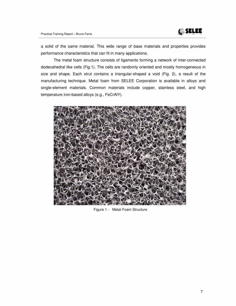
The metal foam structure consists of ligaments forming a network of inter-connected
dodecahedral like cells (Fig.1). The cells are randomly oriented and mostly homogeneous in
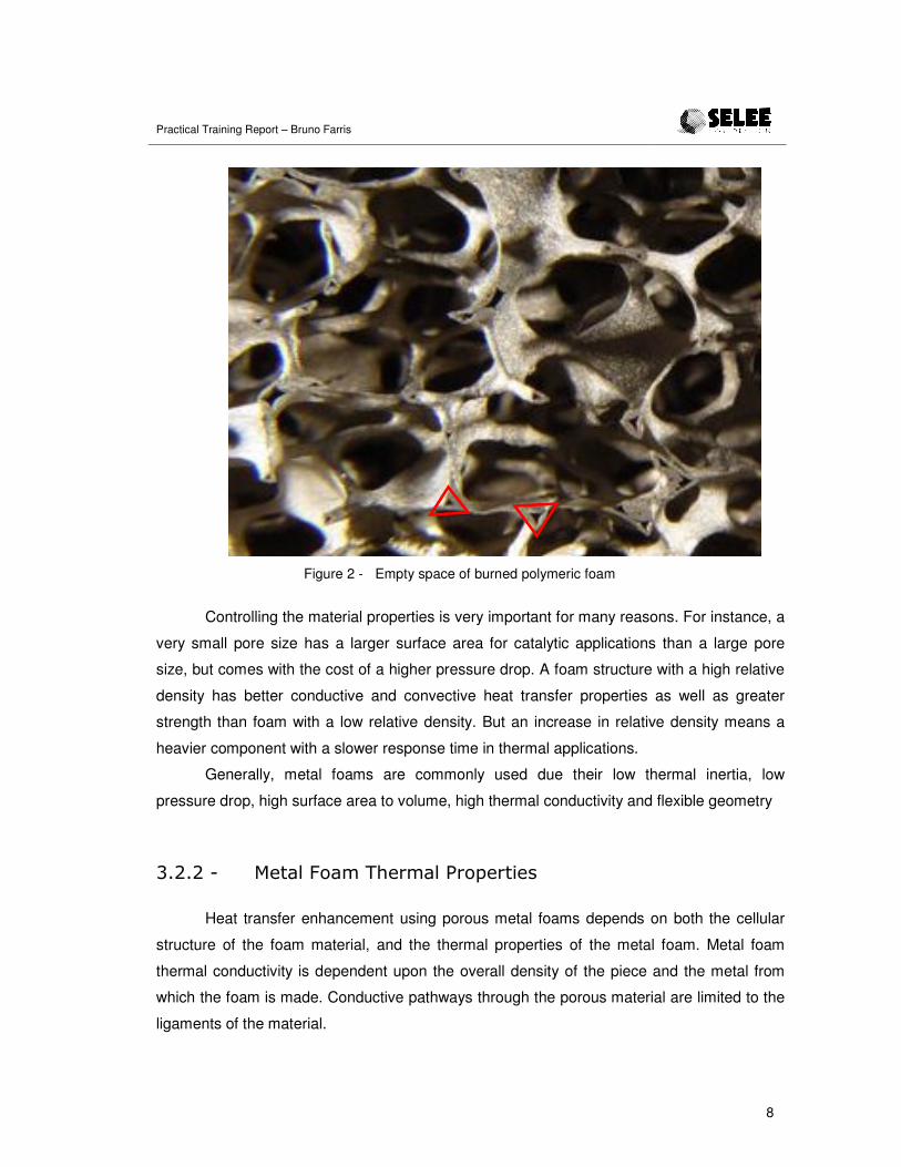
size and shape. Each strut contains a triangular-shaped a void (Fig. 2), a result of the
manufacturing technique. Metal foam from SELEE Corporation is available in alloys and
single-element materials. Common materials include copper, stainless steel, and high
temperature iron-based alloys (e.g., FeCrAlY).
Figure 1 - Metal Foam Structure
Practical Training Report – Bruno Farris
8
Figure 2 - Empty space of burned polymeric foam
Controlling the material properties is very important for many reasons. For instance, a
very small pore size has a larger surface area for catalytic applications than a large pore
size, but comes with the cost of a higher pressure drop. A foam structure with a high relative
density has better conductive and convective heat transfer properties as well as greater
strength than foam with a low relative density. But an increase in relative density means a
heavier component with a slower response time in thermal applications.
Generally, metal foams are commonly used due their low thermal inertia, low
pressure drop, high surface area to volume, high thermal conductivity and flexible geometry
�������� !,$"��&$-��(!%-$"��%&'!%,/!.�
Heat transfer enhancement using porous metal foams depends on both the cellular
structure of the foam material, and the thermal properties of the metal foam. Metal foam
thermal conductivity is dependent upon the overall density of the piece and the metal from
which the foam is made. Conductive pathways through the porous material are limited to the
ligaments of the material.
Practical Training Report – Bruno Farris
9
Higher thermal conductivity is associated with higher density materials, and significant
increase in thermal conductivity results from an increase in material density. On the other
hand, heat transfer by metal foams due to thermal dispersion effects is proportional to cell
size. In general, decreasing the pore size and/or decreasing the void fraction lead to higher
rates of heat transfer given a constant fluid velocity. However, most practical systems are
restricted by the pumping power that can be achieved and therefore, the fluid velocity cannot
be maintained as the void fraction and/or pore size is decreased.
�������� !,$"��&$-��$0%/1$,/&2�
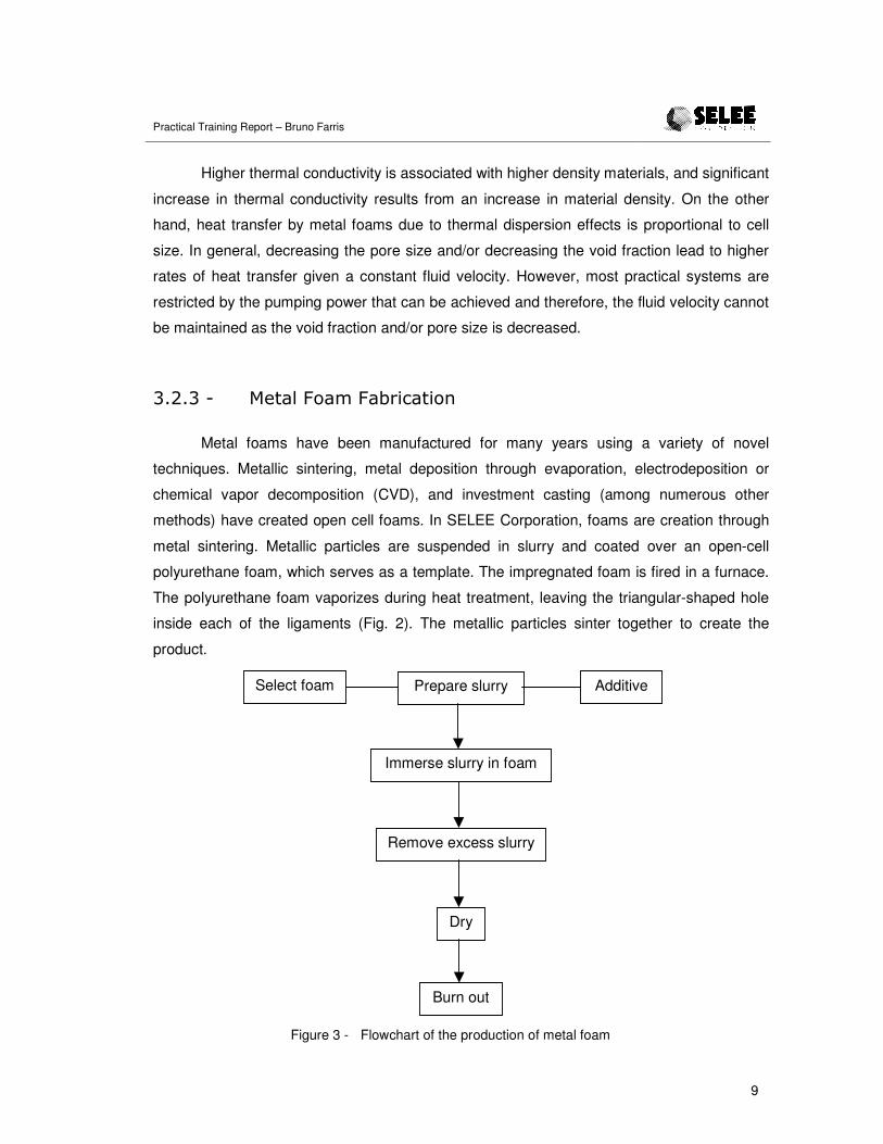
Metal foams have been manufactured for many years using a variety of novel
techniques. Metallic sintering, metal deposition through evaporation, electrodeposition or
chemical vapor decomposition (CVD), and investment casting (among numerous other
methods) have created open cell foams. In SELEE Corporation, foams are creation through
metal sintering. Metallic particles are suspended in slurry and coated over an open-cell
polyurethane foam, which serves as a template. The impregnated foam is fired in a furnace.
The polyurethane foam vaporizes during heat treatment, leaving the triangular-shaped hole
inside each of the ligaments (Fig. 2). The metallic particles sinter together to create the
product.
Figure 3 - Flowchart of the production of metal foam
Prepare slurry AdditiveSelect foam
Immerse slurry in foam
Remove excess slurry
Dry
Burn out

Practical Training Report – Bruno Farris
10
This process involves coating different flexible, open-cell polymeric foam that can be
used for the precursor foam; these include poly-urethane (PU), polyvinyl-chloride (PVC),
polystyrene (PS) and others. It must be able to spring back after being squeezed out. The
production of a reticulated metal foam component begins with the machining of the original
polymer foam to the desired shape. Theoretically, there are relatively few limitations on the
shape that can be produced.
Since the final metal foam is a direct replica of the original foam, the polymer foam
structure and pore size are critical in determining the properties of the final component (i.e.
density and permeability). The polymeric foam must be bigger than the final size due to
shrinkage, which ranges for each material base.
Generally, any fine metal powder can be used that can be made into a suitable
suspension. The slurry is a mixture of the metal powder plus inorganic components that can
be flocculating agents, defoaming agent, binder, glue, and others.
Once the polymer foam and ceramic slurry are ready, the coating process is carried
out. This involves immersing the foam in the slurry and compressing it to remove air. While
still in the slurry, the foam is allowed to expand again, causing the slurry to be sucked into
the open cells of the foam. This step can be repeated several times to achieve the desired
coating density (usually measured by the wet foam weight). Afterwards, airflow is passed
through the foam to clean up some pores that can be blocked.
When the foam has been coated appropriately, it is dried in an oven to solidify the
metal structure, after which it is exposed to an initial thermal treatment that is designed to
burn out the polymer foam inside the ceramic struts as well remove any organic additives
from the slurry. The sintering temperature depends on the composition metal powder. The
process can be performed in air or any other type of atmosphere as appropriate.
This method is thought to be the most cost-effective and the most amenable to mass
production. Necessary production equipment is easily automated and yields high-quality,
low-cost metal foam materials for use in a variety of applications.
Practical Training Report – Bruno Farris
11
����� ������������
������ &'+1&'2�
On the first day, I was introduced to the company. I had some meetings to learn about
how the company works, safety, proper use of computer (policy conditions), quality,
environmental and safety policy, a corporate overview, and a tour through the plant to see
the process.
To understand better the process, to know the employees and improve the language,
during the first weeks, I worked in all parts of production of metal foam, which included
pressing foam, quality testing and others.
After that, I started to participate in meetings in the R&D department where I had
different activities assigned. In this report, the four main activities are described in sequence.
����������3+'$4$��+,-+'.%4'+�./2��'(#/5�
The goal of this experiment was to evaluate the viscosity change in Phosphate-
Bonded Alumina, or PBA, with temperature and drying. To execute the test, we used an
AR1000 Rheometer. To make sure the test would represent exactly what happens, PBA
slurry was obtained from the line for testing.
�������� �!.,�
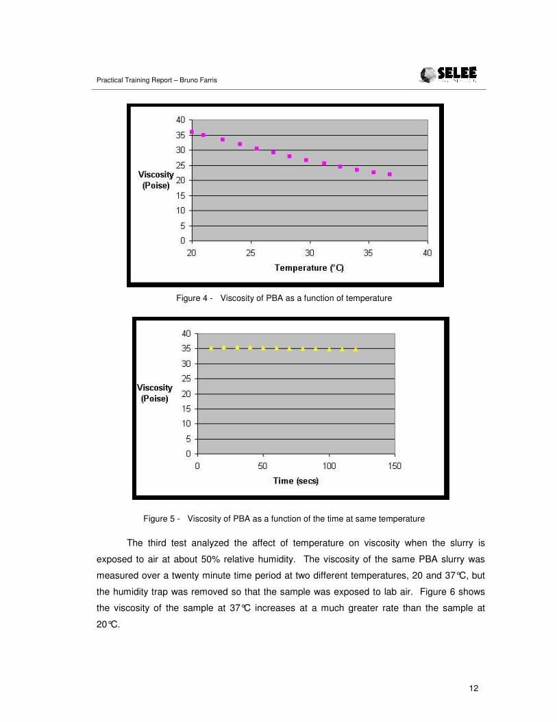
The first test was designed to determine how the viscosity of PBA changed with
temperature. The shear rate was kept constant at 100 s-1, and the temperature was ramped
from 20 to 37°C (68 to 98.6°F, respectively) over two minutes. A humidity trap was in place
to insure the slurry would not dry during the test.
To insure the decrease was not due to thixotropic effects (i.e. change in viscosity due
to time at shear), a second test was run at constant temperature (20°C) over the same two
minute time period and same shear rate. Figure 4 shows the viscosity decreased as the
temperature increased. Figure 5 shows the viscosity was constant during this test, so the
response in Figure 4 is entirely due to temperature.
Practical Training Report – Bruno Farris
12
Figure 4 - Viscosity of PBA as a function of temperature
Figure 5 - Viscosity of PBA as a function of the time at same temperature
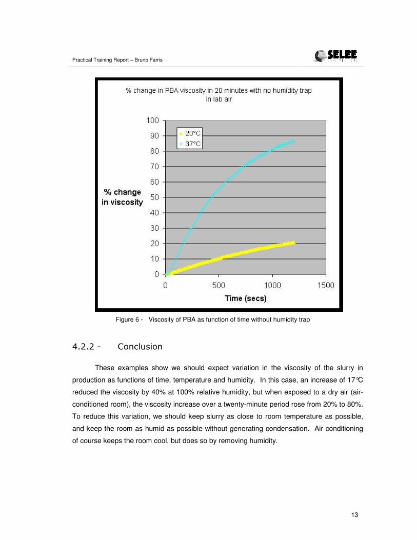
The third test analyzed the affect of temperature on viscosity when the slurry is
exposed to air at about 50% relative humidity. The viscosity of the same PBA slurry was
measured over a twenty minute time period at two different temperatures, 20 and 37°C, but
the humidity trap was removed so that the sample was exposed to lab air. Figure 6 shows
the viscosity of the sample at 37°C increases at a much greater rate than the sample at
20°C.
Practical Training Report – Bruno Farris
13
Figure 6 - Viscosity of PBA as function of time without humidity trap
�������� �&21"#./&2�
These examples show we should expect variation in the viscosity of the slurry in
production as functions of time, temperature and humidity. In this case, an increase of 17°C
reduced the viscosity by 40% at 100% relative humidity, but when exposed to a dry air (air-
conditioned room), the viscosity increase over a twenty-minute period rose from 20% to 80%.
To reduce this variation, we should keep slurry as close to room temperature as possible,
and keep the room as humid as possible without generating condensation. Air conditioning
of course keeps the room cool, but does so by removing humidity.

Practical Training Report – Bruno Farris
14
�������04''(��*.'.6%+'#7.%#&/�
The company was having some problems with Fe-Cr-Al-Y slurry. During the process
of impregnation, its properties changed, resulting in some differences in the parts. The
proposal was to try to characterize the slurry as a function of the time. The main goal was to
gather data on viscosity, specific gravity and solid contents as parts were manufactured, and
correlate these data with problems that arise.
�������� �3'!%/-!2,�4!.1%/',/&2�
A viscometer was used to measure viscosity of the slurry. To get the specific gravity,
a known volume recipient is used. The recipient is filled and then mass is divided by the
volume. The solids contents is determined by calculating the difference between wet and dry
weights. This characterization was made during production of FeCrAlY metal foam.
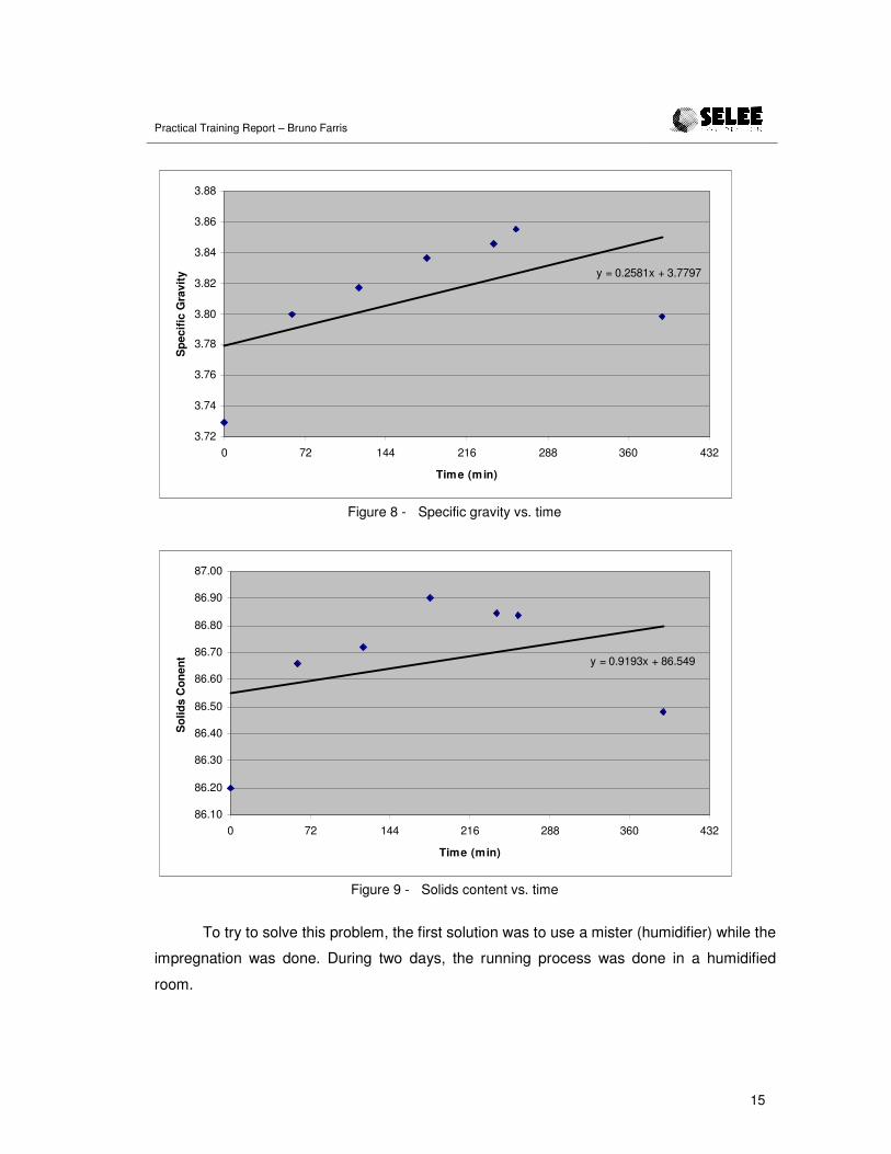
�������� �!.#",.�
All checked variables – viscosity, specific gravity and solids content – increased with
the time. It means water was lost with time. In sequence there are the graphics of one day of
characterization.
y = 19.497x + 36.054
0
5
10
15
20
25
30
35
40
45
0 72 144 216 288 360 432
Time (min)
Vis
cosi
ty
Figure 7 - Viscosity vs. time
Practical Training Report – Bruno Farris
15
y = 0.2581x + 3.7797
3.72
3.74
3.76
3.78
3.80
3.82
3.84
3.86
3.88
0 72 144 216 288 360 432
Time (min)
Spe
cific
Gra
vity
Figure 8 - Specific gravity vs. time
y = 0.9193x + 86.549
86.10
86.20
86.30
86.40
86.50
86.60
86.70
86.80
86.90
87.00
0 72 144 216 288 360 432
Time (min)
Sol
ids
Con
ent
Figure 9 - Solids content vs. time
To try to solve this problem, the first solution was to use a mister (humidifier) while the
impregnation was done. During two days, the running process was done in a humidified
room.
Practical Training Report – Bruno Farris
16
�������� �&21"#./&2�
The water loss as a function of time is about 2.0 g/min. For the run with the mister,
the water loss was about 1.95 g/min for the first 180 minutes. Because the mister did not
have a big impact on increasing solids content, the loss can be a function of impregnation,
and thus related to number of blanks are run through the machine. This means the rate of
water loss is more a function of how many blanks are run as a function of time, just not time
itself. We did discover that the humidifier kept the slurry from frying on the machine, so its
use will continue
Others solutions will be tested, like deliver a quantity of water close to these amounts
as a function of time. A drip of water from a pipette is about 0.02-0.03 g, so this is about 1
drip per second.
������ 0+8#9#0#%(��+.$4'+,+/%�
About 8500 pieces were sent back to Porvair for flex testing. The customer
complained that the parts were not good, and asked to do the tests again.
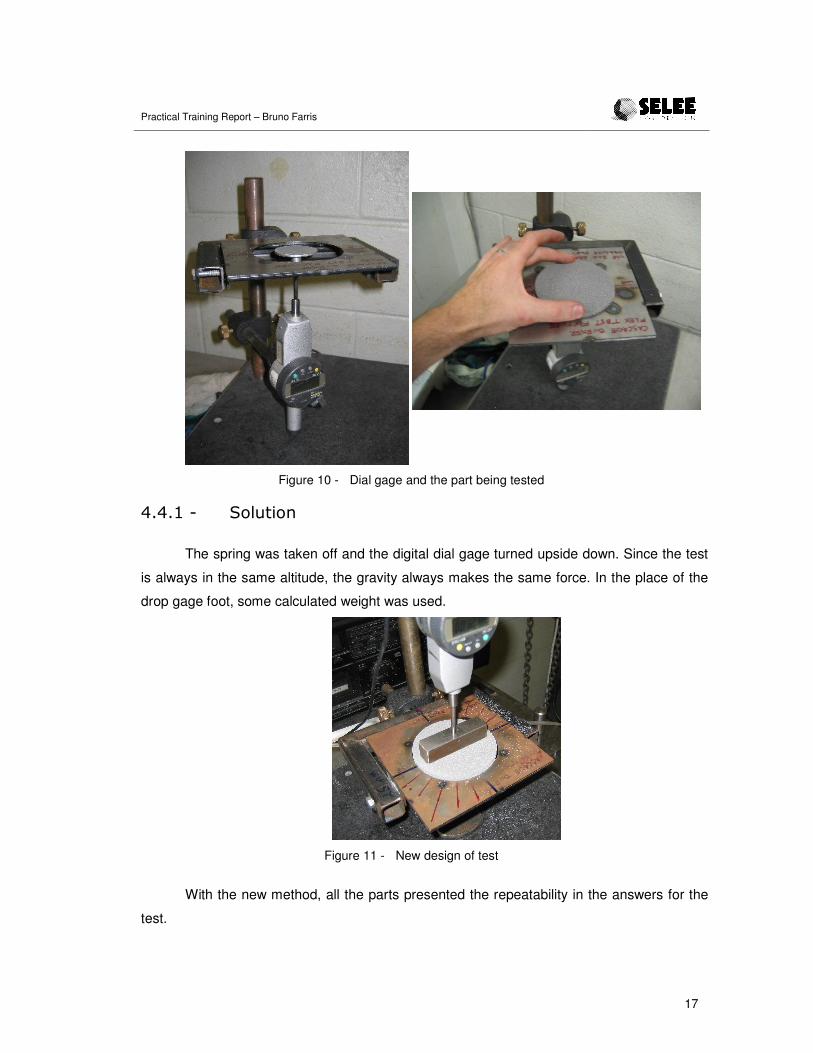
The test was conducted using the test fixture in figure 10. A part was placed in the
test fixture. A digital dial gage used to make some force against the part, folding it. The
distance was measured with the same digital gage. One problem with the test was the spring
could not always return to the same position, making the zero change all the time and also
the answer.
Practical Training Report – Bruno Farris
17
Figure 10 - Dial gage and the part being tested
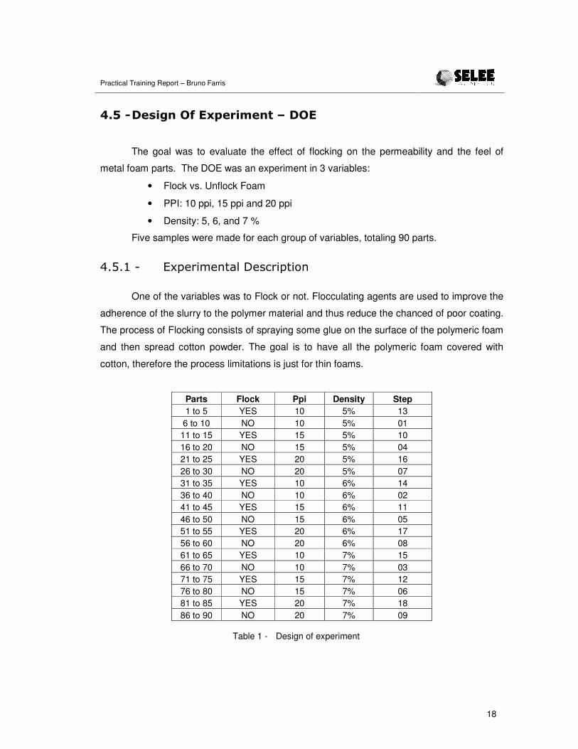
�������� �&"#,/&2�
The spring was taken off and the digital dial gage turned upside down. Since the test
is always in the same altitude, the gravity always makes the same force. In the place of the
drop gage foot, some calculated weight was used.
Figure 11 - New design of test
With the new method, all the parts presented the repeatability in the answers for the
test.
Practical Training Report – Bruno Farris
18
�� ����+$#5/��)��8-+'#,+/%�!�����
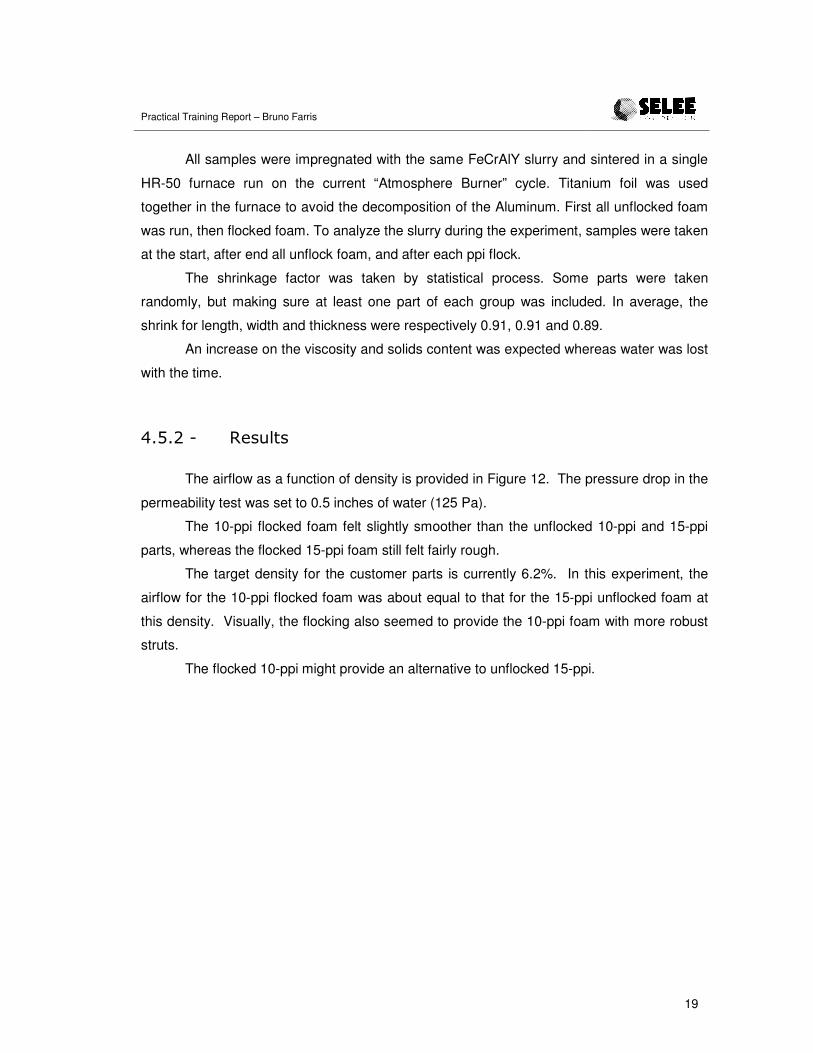
The goal was to evaluate the effect of flocking on the permeability and the feel of
metal foam parts. The DOE was an experiment in 3 variables:
• Flock vs. Unflock Foam
• PPI: 10 ppi, 15 ppi and 20 ppi
• Density: 5, 6, and 7 %
Five samples were made for each group of variables, totaling 90 parts.
�� ����� �3'!%/-!2,$"��!.1%/',/&2�
One of the variables was to Flock or not. Flocculating agents are used to improve the
adherence of the slurry to the polymer material and thus reduce the chanced of poor coating.
The process of Flocking consists of spraying some glue on the surface of the polymeric foam
and then spread cotton powder. The goal is to have all the polymeric foam covered with
cotton, therefore the process limitations is just for thin foams.
Parts Flock Ppi Density Step 1 to 5 YES 10 5% 13
6 to 10 NO 10 5% 01 11 to 15 YES 15 5% 10 16 to 20 NO 15 5% 04 21 to 25 YES 20 5% 16 26 to 30 NO 20 5% 07 31 to 35 YES 10 6% 14 36 to 40 NO 10 6% 02 41 to 45 YES 15 6% 11 46 to 50 NO 15 6% 05 51 to 55 YES 20 6% 17 56 to 60 NO 20 6% 08 61 to 65 YES 10 7% 15 66 to 70 NO 10 7% 03 71 to 75 YES 15 7% 12 76 to 80 NO 15 7% 06 81 to 85 YES 20 7% 18 86 to 90 NO 20 7% 09
Table 1 - Design of experiment
Practical Training Report – Bruno Farris
19
All samples were impregnated with the same FeCrAlY slurry and sintered in a single
HR-50 furnace run on the current “Atmosphere Burner” cycle. Titanium foil was used
together in the furnace to avoid the decomposition of the Aluminum. First all unflocked foam
was run, then flocked foam. To analyze the slurry during the experiment, samples were taken
at the start, after end all unflock foam, and after each ppi flock.
The shrinkage factor was taken by statistical process. Some parts were taken
randomly, but making sure at least one part of each group was included. In average, the
shrink for length, width and thickness were respectively 0.91, 0.91 and 0.89.
An increase on the viscosity and solids content was expected whereas water was lost
with the time.
�� ����� �!.#",.�
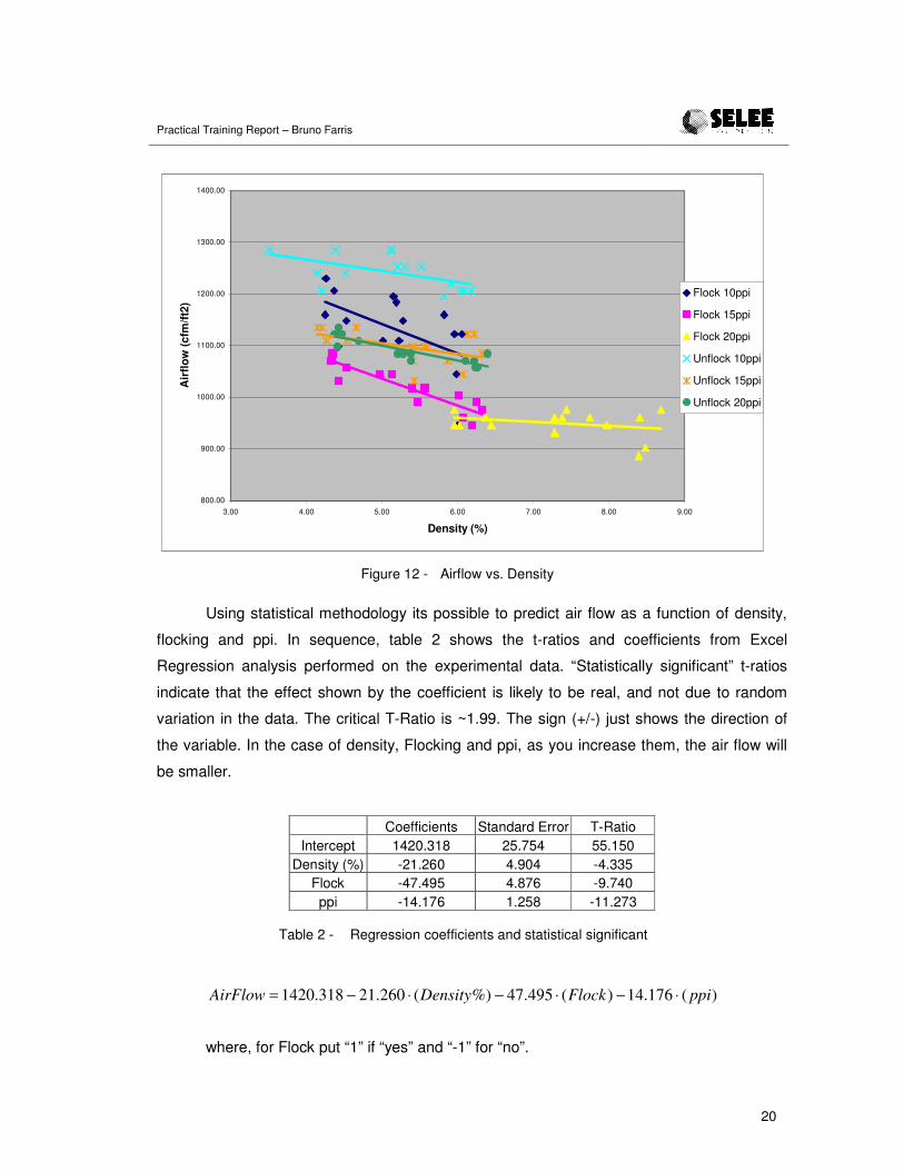
The airflow as a function of density is provided in Figure 12. The pressure drop in the
permeability test was set to 0.5 inches of water (125 Pa).
The 10-ppi flocked foam felt slightly smoother than the unflocked 10-ppi and 15-ppi
parts, whereas the flocked 15-ppi foam still felt fairly rough.
The target density for the customer parts is currently 6.2%. In this experiment, the
airflow for the 10-ppi flocked foam was about equal to that for the 15-ppi unflocked foam at
this density. Visually, the flocking also seemed to provide the 10-ppi foam with more robust
struts.
The flocked 10-ppi might provide an alternative to unflocked 15-ppi.
Practical Training Report – Bruno Farris
20
800.00
900.00
1000.00
1100.00
1200.00
1300.00
1400.00
3.00 4.00 5.00 6.00 7.00 8.00 9.00
Density (%)
Air
flow
(cfm
/ft2)
Flock 10ppi
Flock 15ppi
Flock 20ppi
Unflock 10ppi
Unflock 15ppi
Unflock 20ppi
Figure 12 - Airflow vs. Density
Using statistical methodology its possible to predict air flow as a function of density,
flocking and ppi. In sequence, table 2 shows the t-ratios and coefficients from Excel
Regression analysis performed on the experimental data. “Statistically significant” t-ratios
indicate that the effect shown by the coefficient is likely to be real, and not due to random
variation in the data. The critical T-Ratio is ~1.99. The sign (+/-) just shows the direction of
the variable. In the case of density, Flocking and ppi, as you increase them, the air flow will
be smaller.
Coefficients Standard Error T-Ratio Intercept 1420.318 25.754 55.150
Density (%) -21.260 4.904 -4.335 Flock -47.495 4.876 -9.740 ppi -14.176 1.258 -11.273
Table 2 - Regression coefficients and statistical significant
)(176.14)(495.47%)(260.21318.1420 ppiFlockDensityAirFlow ⋅−⋅−⋅−=
where, for Flock put “1” if “yes” and “-1” for “no”.

Practical Training Report – Bruno Farris
21
Using the equation for “Airflow” and predicting for 15ppi unflocked and 10ppi flocked,
both at 6.2% density, the Airflow should be 1123 and 1099 cfm/ft2 respective. Its confirms
that the flocked 10-ppi might provide an alternative to unflocked 15-ppi.
���� ���������
This first period of practical training was already an excellent term of learning. This
peculiar department is a special place to learn how the process and its respective variables
works.
Beyond the four activities detailed, I always had some help, but usually, all the
process was given for me, making me think a lot, learn and having some responsibilities, just
like an engineer. The opportunity of working with different people on various projects was
also very important for the success of this first period.
The possibility of carrying out this practical training abroad in a multinational company
contributes a lot for my professional career. Moreover to live abroad and experience a
different culture and language is very important for a global view of the world.
����� �� ��������
[1] SELEE Corporation Internet website. http://www.selee.com/
[2] Porvair Advanced Materials Internet website.
http://www.porvairadvancedmaterials.com
[3] SELEE Corporation Intranet website http://intranet/
[4] Haack, D.P., Butcher, K.R., Kim, T., and Lu, T.J., “Novel Lightweight Metal Foam
Heat Exchangers”
[5] Scheffler, Michael and Colombo, Paolo, “Cellular Ceramics”