Embed Size (px)
Citation preview
Practices for High-tension Cable
Barriers
Providence, Rhode Island
Wednesday, August 2, 2017
Presented to the AASHTO
Subcommittee on Maintenance
To identify and report on the state of the practice for
HTCBs used in medians, including:
• Specifications and special provisions
• Design standards, criteria, and warrants
• Construction and maintenance procedures
• Need for additional study
2
Synthesis Objectives
3
Project Team
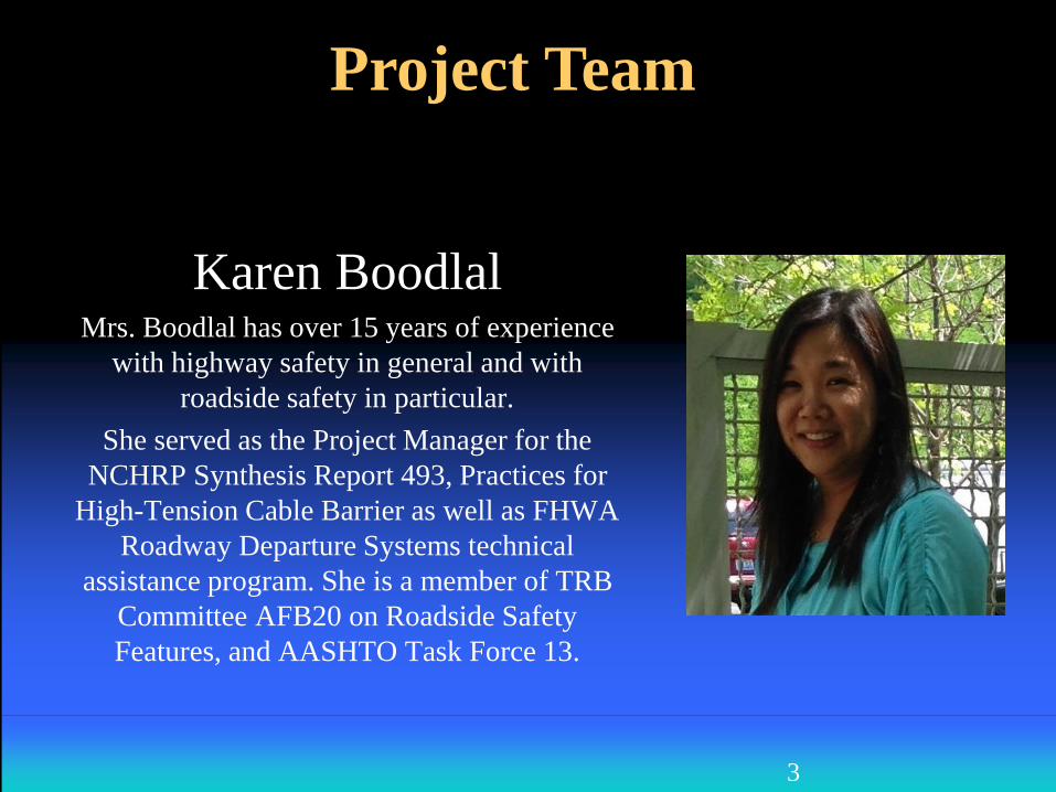
Karen BoodlalMrs. Boodlal has over 15 years of experience
with highway safety in general and with
roadside safety in particular.
She served as the Project Manager for the
NCHRP Synthesis Report 493, Practices for
High-Tension Cable Barrier as well as FHWA
Roadway Departure Systems technical
assistance program. She is a member of TRB
Committee AFB20 on Roadside Safety
Features, and AASHTO Task Force 13.
4
Project Team
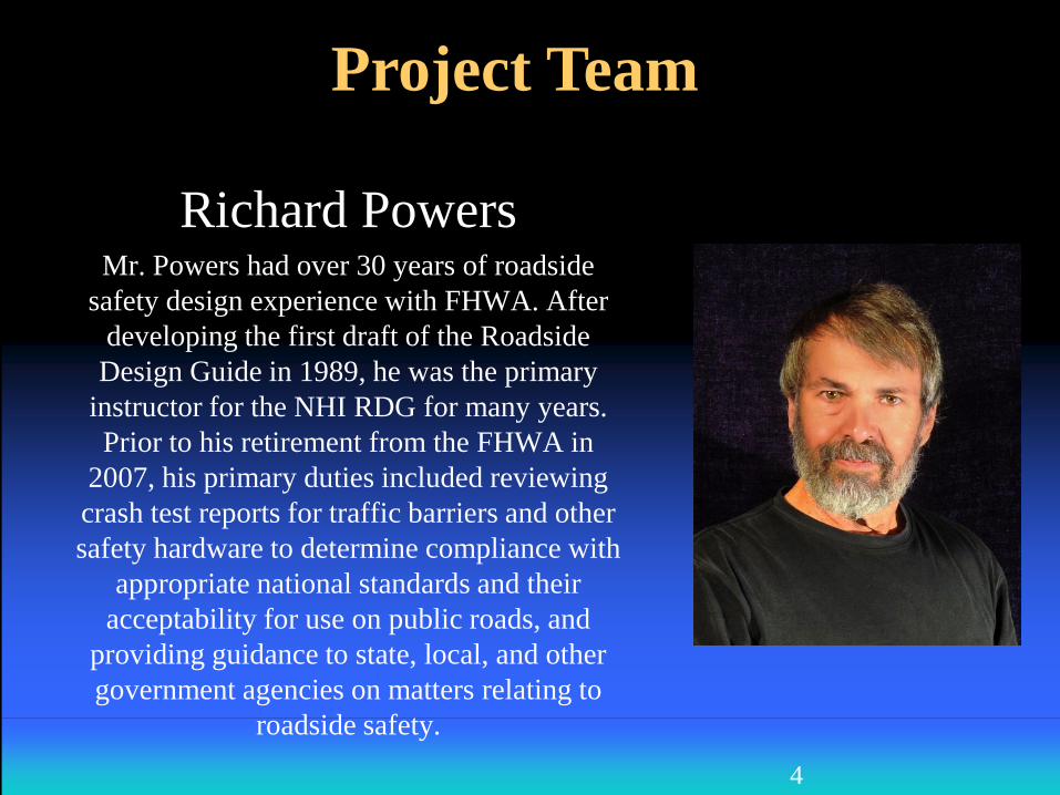
Richard PowersMr. Powers had over 30 years of roadside
safety design experience with FHWA. After
developing the first draft of the Roadside
Design Guide in 1989, he was the primary
instructor for the NHI RDG for many years.
Prior to his retirement from the FHWA in
2007, his primary duties included reviewing
crash test reports for traffic barriers and other
safety hardware to determine compliance with
appropriate national standards and their
acceptability for use on public roads, and
providing guidance to state, local, and other
government agencies on matters relating to
roadside safety.
PHOTO
On top of Cable Barrier for 50 yrs.
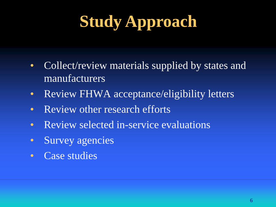
• Collect/review materials supplied by states and
manufacturers
• Review FHWA acceptance/eligibility letters
• Review other research efforts
• Review selected in-service evaluations
• Survey agencies
• Case studies
6
Study Approach
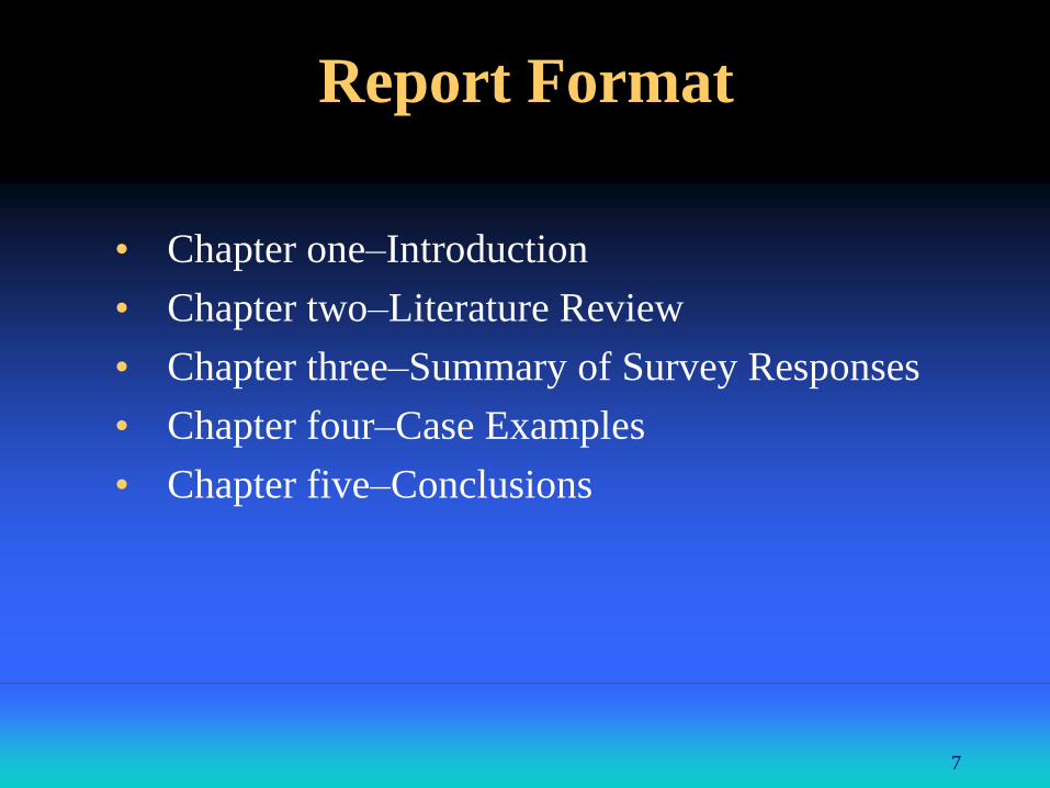
• Chapter one–Introduction
• Chapter two–Literature Review
• Chapter three–Summary of Survey Responses
• Chapter four–Case Examples
• Chapter five–Conclusions
7
Report Format
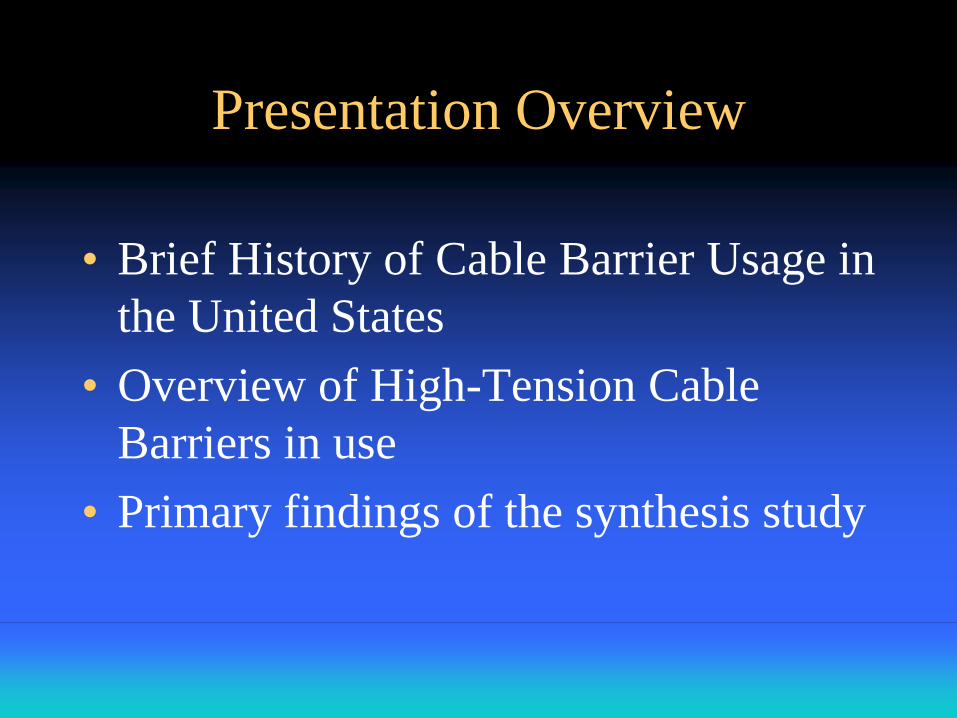
Presentation Overview
• Brief History of Cable Barrier Usage in
the United States
• Overview of High-Tension Cable
Barriers in use
• Primary findings of the synthesis study
• Started as low tension generic design
• Often cost-effective in freeway medians
• First high-tension proprietary design
installed in Oklahoma City around 2000
• Several additional proprietary designs
developed over time
• Significant increase in use to present day
9
History of Cable
Barrier Usage in the United States
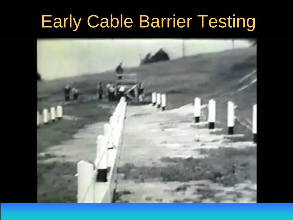
Early Cable Barrier Testing
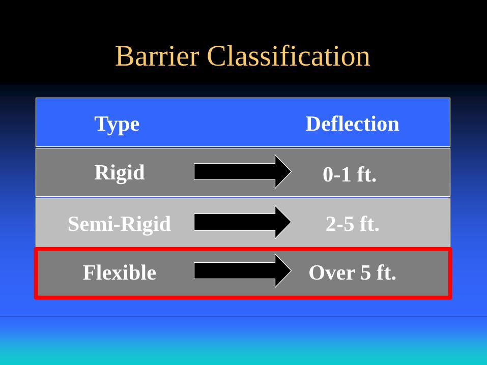
Barrier Classification
Type Deflection
Rigid 0-1 ft.
Semi-Rigid 2-5 ft.
Flexible Over 5 ft.
Types of Flexible Barrier
• W-beam (weak post)
• Low tension cable barriers
• High-tension cable barriers
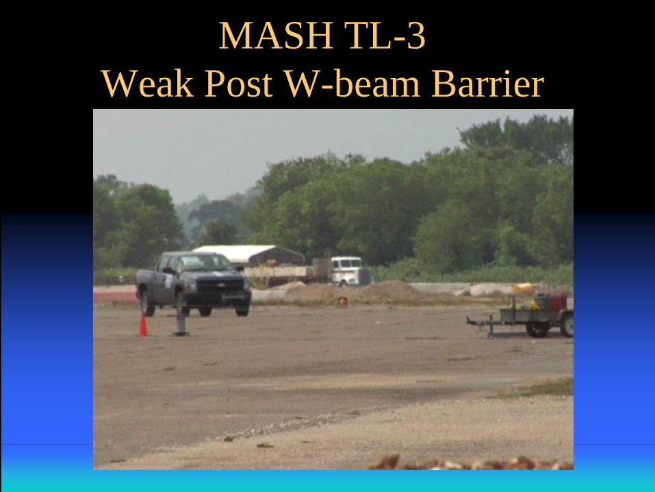
MASH TL-3
Weak Post W-beam Barrier
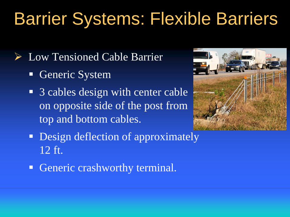
Barrier Systems: Flexible Barriers
Low Tensioned Cable Barrier
Generic System
3 cables design with center cable
on opposite side of the post from
top and bottom cables.
Design deflection of approximately
12 ft.
Generic crashworthy terminal.
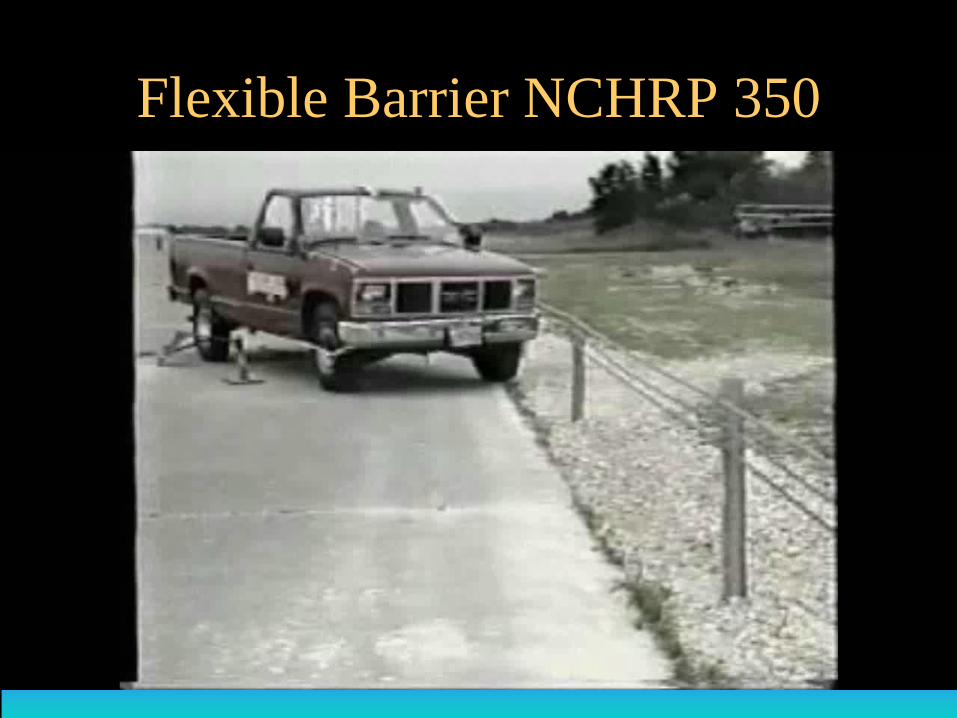
Flexible Barrier NCHRP 350
Barrier Systems: Flexible Barriers
High Tension Cable Barrier
Five different designs available
All designs are proprietary
Each design has less deflection upon impact
than low tension cable barriers
All generally have less damage when struck,
resulting in less maintenance
Each requires a unique proprietary terminal
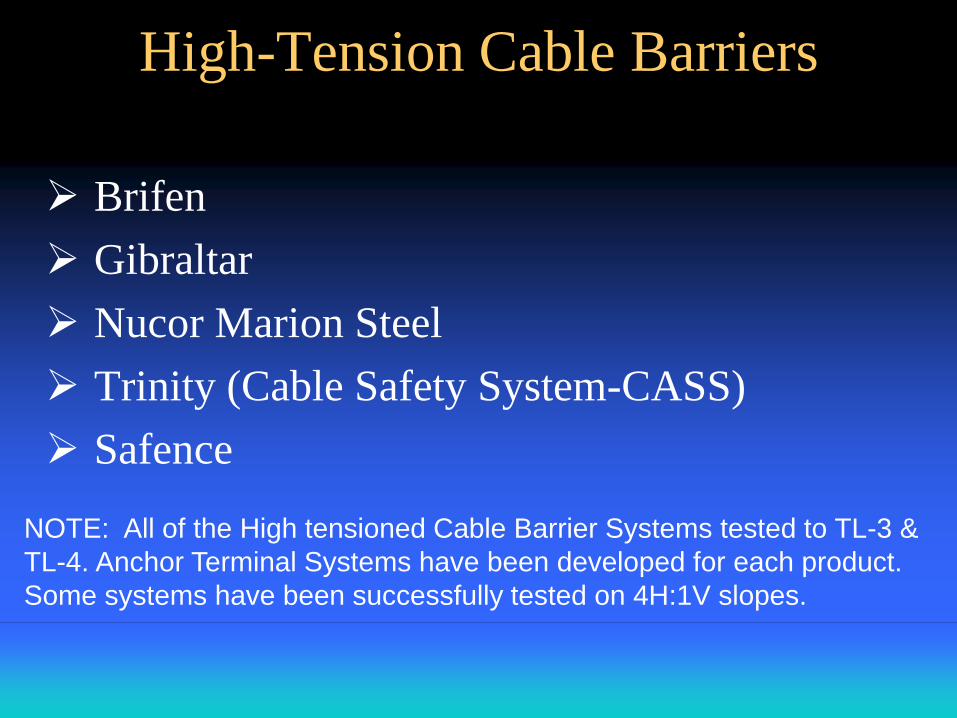
Brifen
Gibraltar
Nucor Marion Steel
Trinity (Cable Safety System-CASS)
Safence
NOTE: All of the High tensioned Cable Barrier Systems tested to TL-3 &
TL-4. Anchor Terminal Systems have been developed for each product.
Some systems have been successfully tested on 4H:1V slopes.
High-Tension Cable Barriers
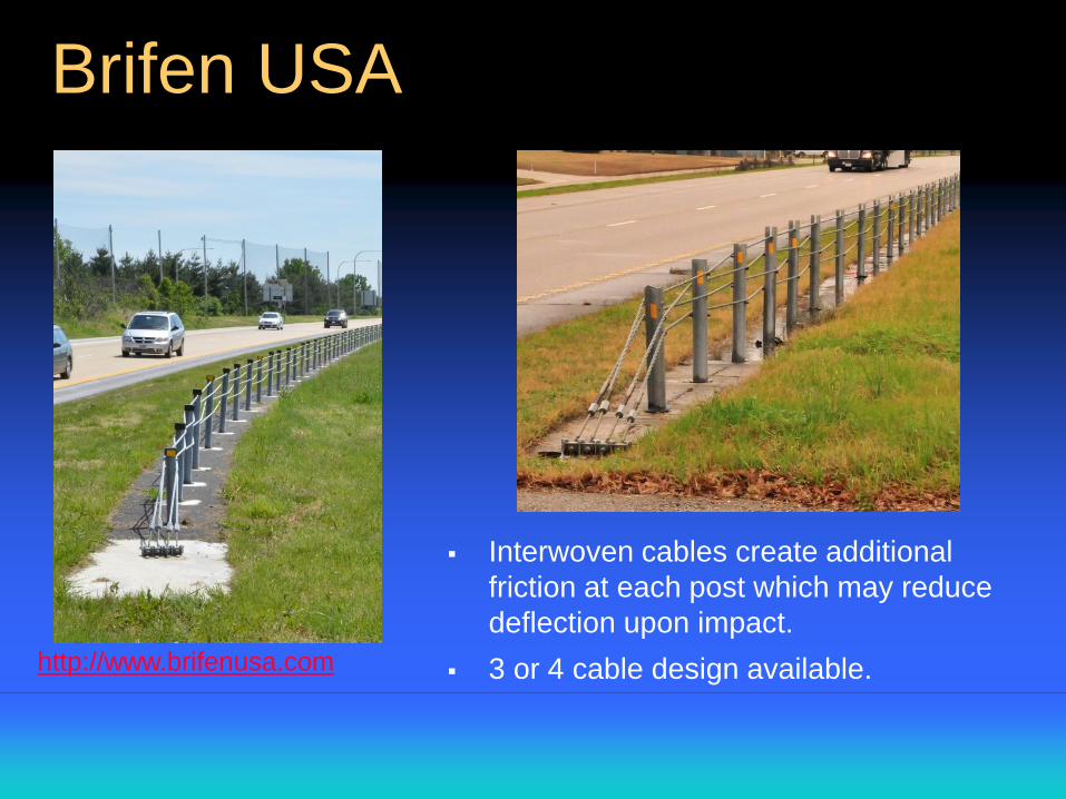
Brifen USA
http://www.brifenusa.com
Interwoven cables create additional
friction at each post which may reduce
deflection upon impact.
3 or 4 cable design available.
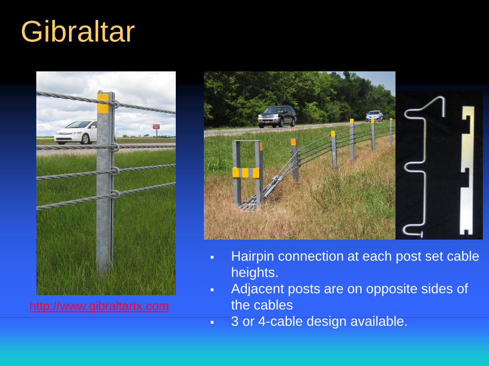
Gibraltar
Hairpin connection at each post set cable
heights.
Adjacent posts are on opposite sides of
the cables
3 or 4-cable design available.http://www.gibraltartx.com
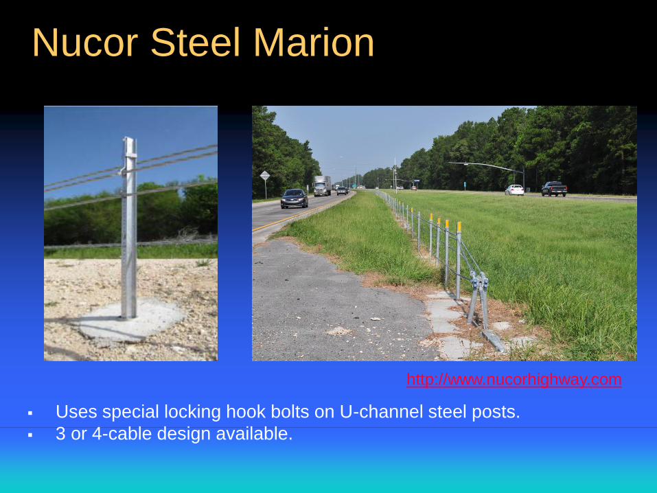
Nucor Steel Marion
http://www.nucorhighway.com
Uses special locking hook bolts on U-channel steel posts.
3 or 4-cable design available.
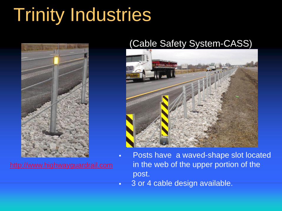
Trinity Industries
http://www.highwayguardrail.com
(Cable Safety System-CASS)
Posts have a waved-shape slot located
in the web of the upper portion of the
post.
3 or 4 cable design available.
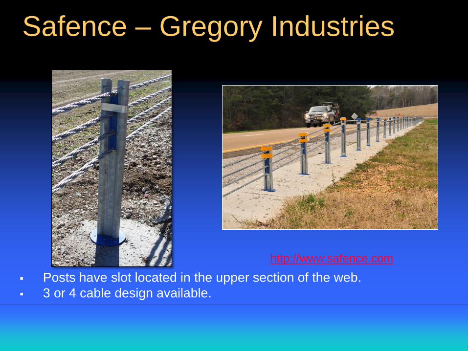
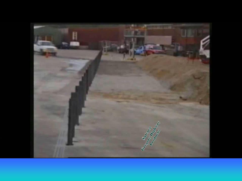
Safence – Gregory Industries
http://www.safence.com
Posts have slot located in the upper section of the web.
3 or 4 cable design available.
• Post can be Direct Driven or Socketed
• Sockets can be Driven or Cast in Concrete
• Posts are placed in Sockets and Cables are hung
from Posts
• Cable heights are pre-determined through hardware
• After a hit, bent Posts are removed and a new Post
is placed in Socket
• Cables are re-hung, tension is checked and system
is ready
Basic Cable Barrier Construction
• Tension is set based on ambient temperature
• Tension is achieved through a two step tensioning -
Initial and Final
• Initial tension is set based on temperature and
system will sit for a pre- determined period of time -
for cable "seating"
• Final tension is set based on temperature after
"seating", tension will fluctuate with temperature
• Tension should be checked and recorded after every
hit
Cable Tension
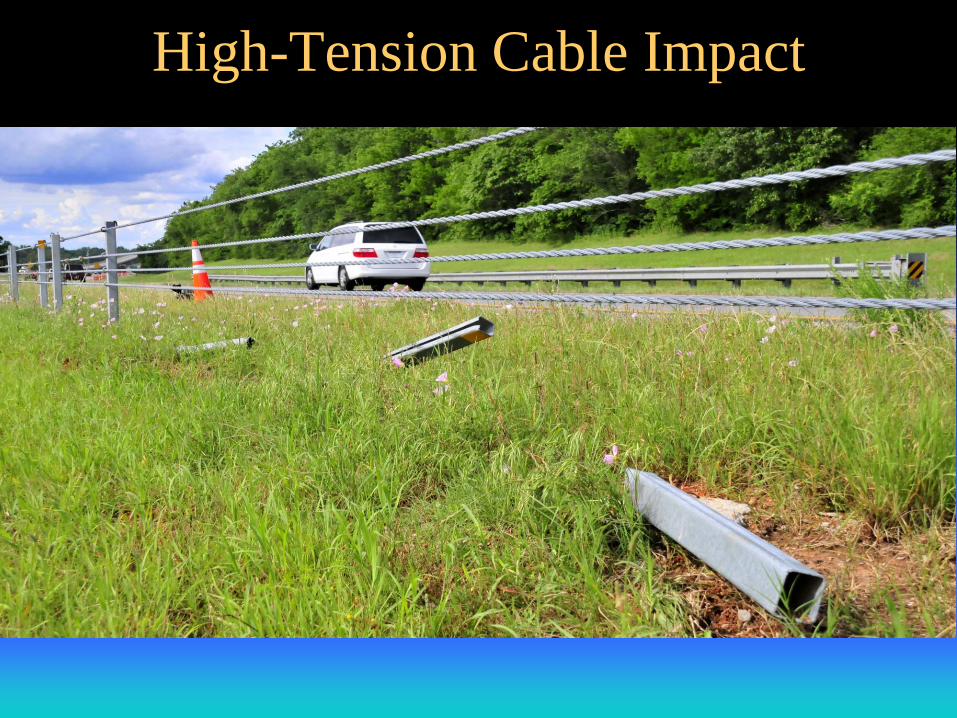
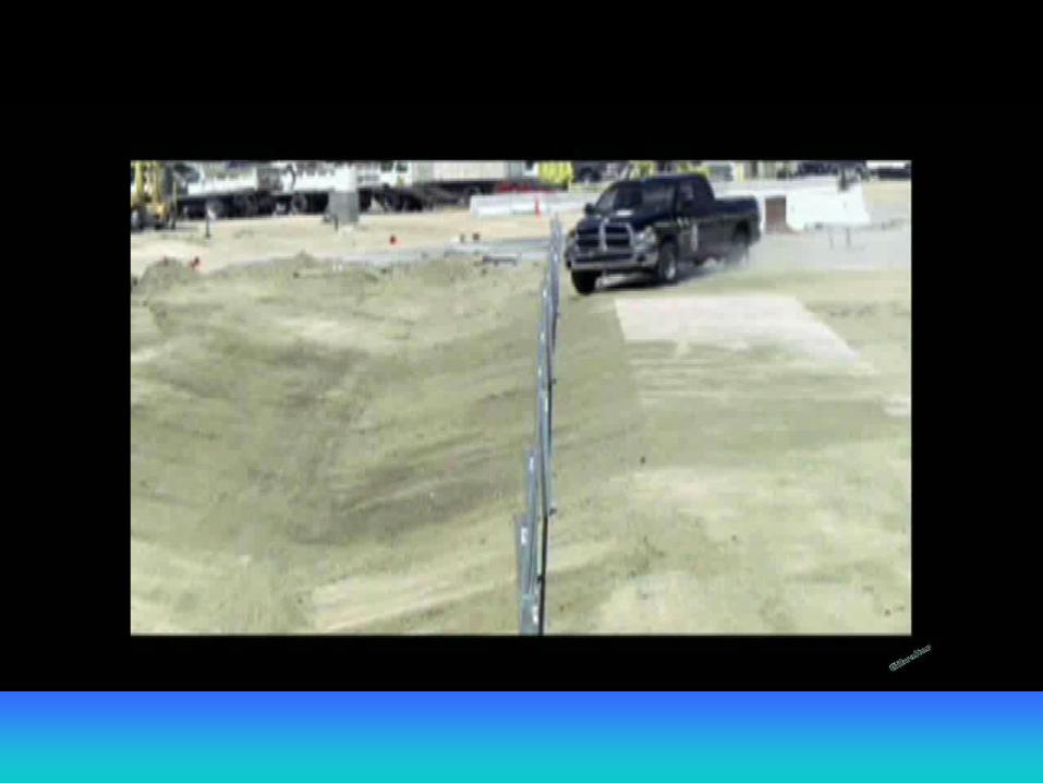
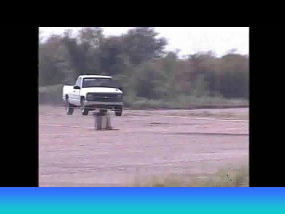
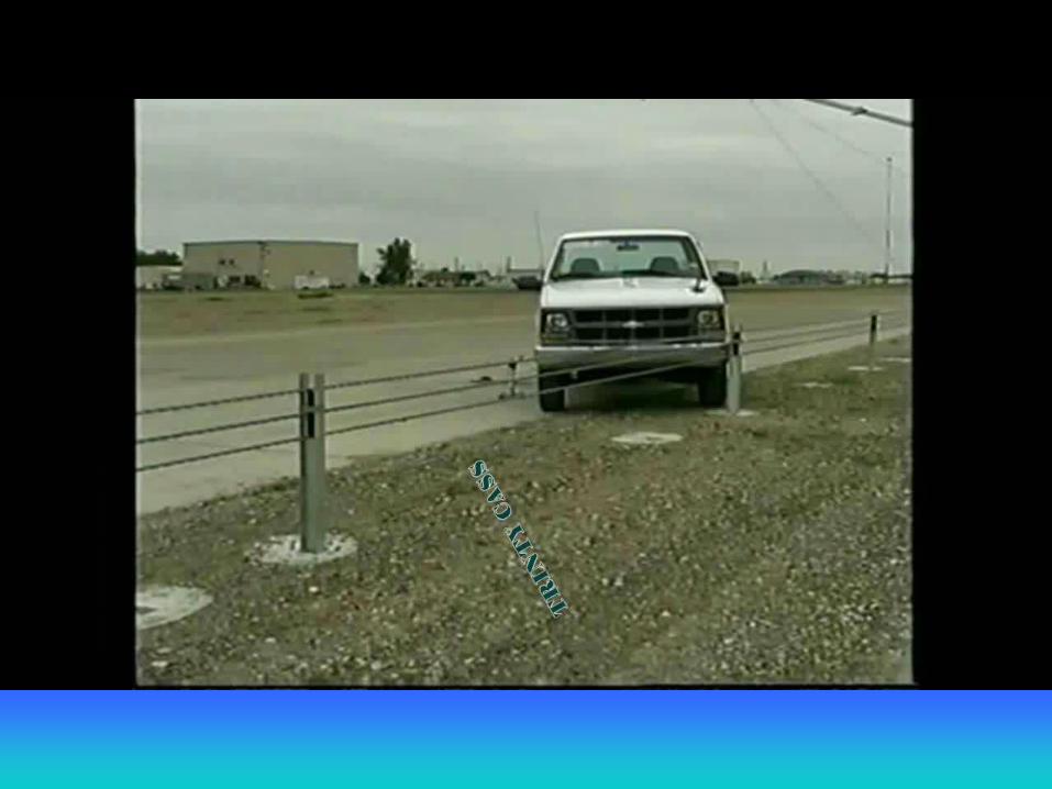
High-Tension Cable Impact
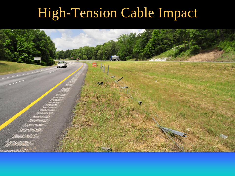
High-Tension Cable Impact
Surveying the States
• Survey was sent out to each State agency by NCHRP.
• Questions were based on HTCB use in the median.
• The survey was divided into three sections:
– Specifications and Design Issues
– Construction Concerns and
– Maintenance Practices
• NCHRP sent out the survey to the SCOD and instructions were
provided on getting input from the agency’s Construction and
Maintenance for completion.
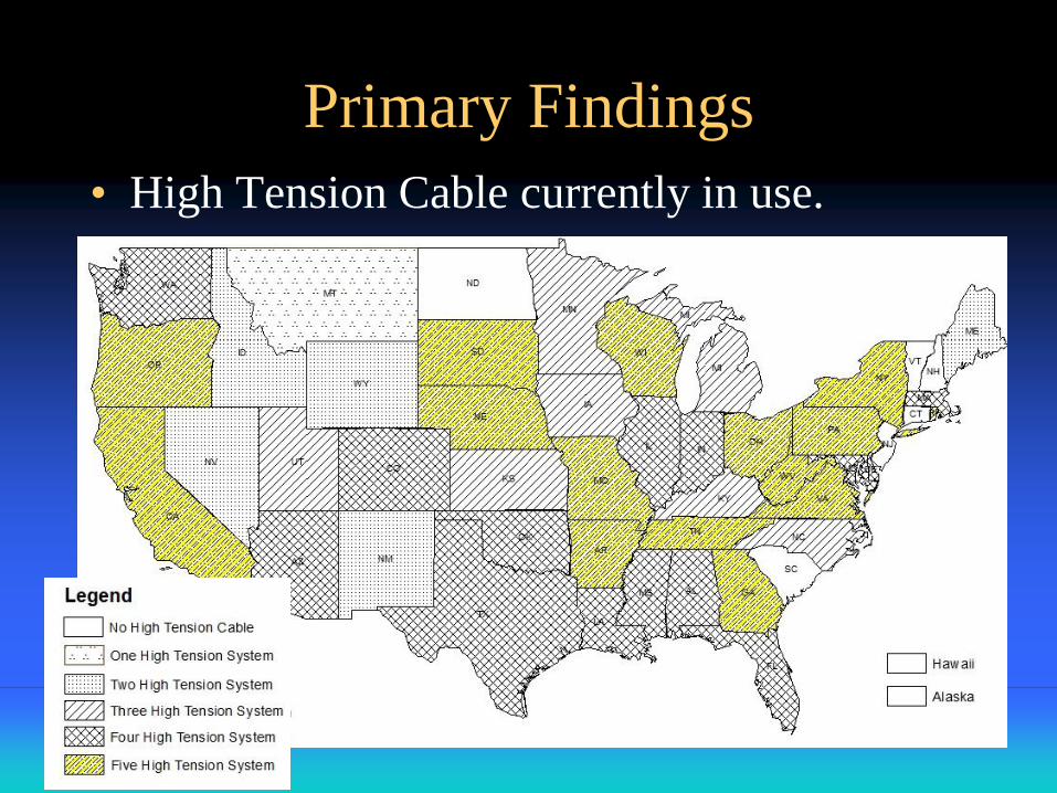
Primary Findings
• High Tension Cable currently in use.
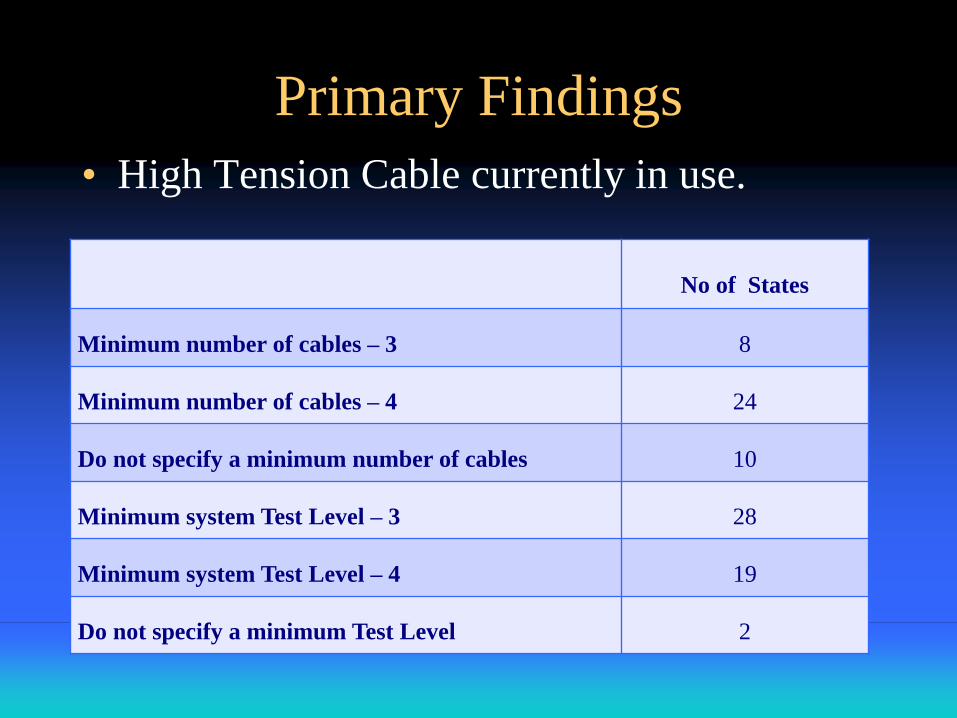
Primary Findings
• High Tension Cable currently in use.
No of States
Minimum number of cables – 3 8
Minimum number of cables – 4 24
Do not specify a minimum number of cables 10
Minimum system Test Level – 3 28
Minimum system Test Level – 4 19
Do not specify a minimum Test Level 2
Primary Findings
• High Tension Cable Specifications/Special Provisions
used by 8 states
• Generic specifications used by 10 states
• Special provisions alone used by 17 states
• Manufacturers specifications/installation manuals used
by 7 states
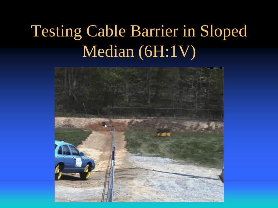
Testing Cable Barrier in Sloped
Median (6H:1V)
Primary Findings
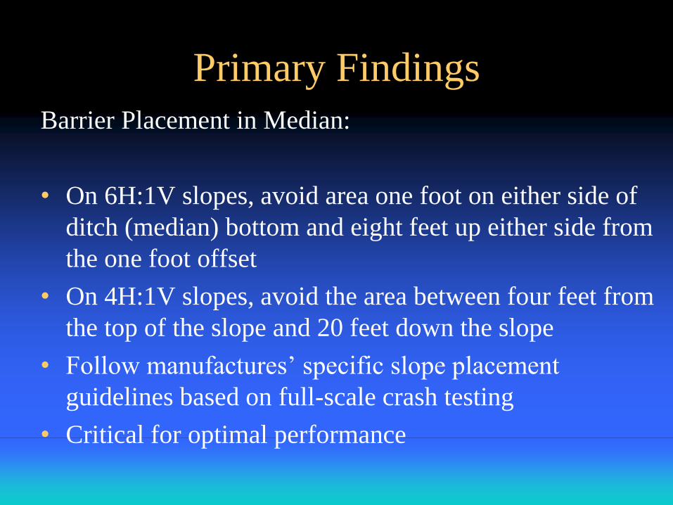
Barrier Placement in Median:
• On 6H:1V slopes, avoid area one foot on either side of
ditch (median) bottom and eight feet up either side from
the one foot offset
• On 4H:1V slopes, avoid the area between four feet from
the top of the slope and 20 feet down the slope
• Follow manufactures’ specific slope placement
guidelines based on full-scale crash testing
• Critical for optimal performance
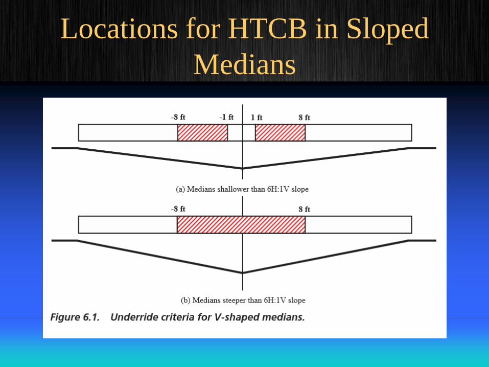
Locations for HTCB in Sloped
Medians
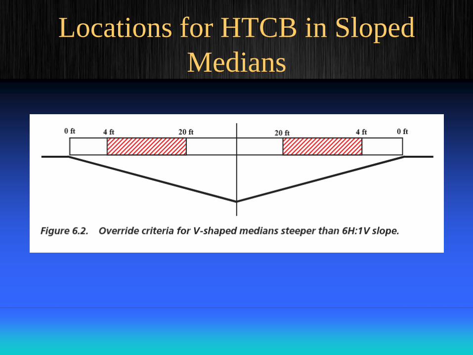
Locations for HTCB in Sloped
Medians
Primary Findings
• HTCB Anchor Placement and spacing are
determined by agency specifications in 16
states and by following the manufacturers’
recommendations in 19 states.
• Some states set a minimum and maximum
cable run between anchors.
• Most states use socketed posts verses driven
posts and require the size and depth of the
sockets be determined by the manufacturer.
Primary Findings
• Overlap/connection to existing W-beam
– Terminate the cable barrier in advance of the
stiffer system
– Terminate the cable barrier behind the stiffer
system
– Terminate the cable barrier in front of the stiffer
system (excluding concrete barrier)
– Connect the cable barrier to the stiffer system
(excluding concrete barrier)
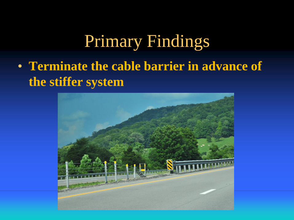
Primary Findings
• Terminate the cable barrier in advance of
the stiffer system
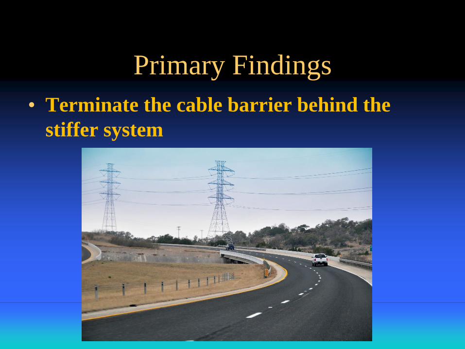
Primary Findings
• Terminate the cable barrier behind the
stiffer system
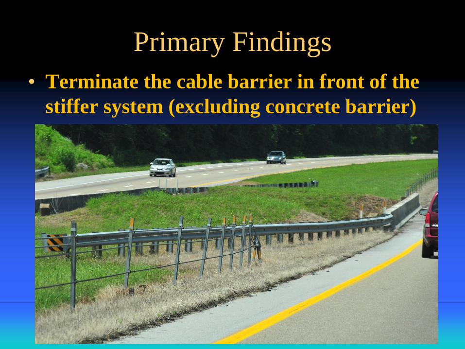
Primary Findings
• Terminate the cable barrier in front of the
stiffer system (excluding concrete barrier)
Primary Findings
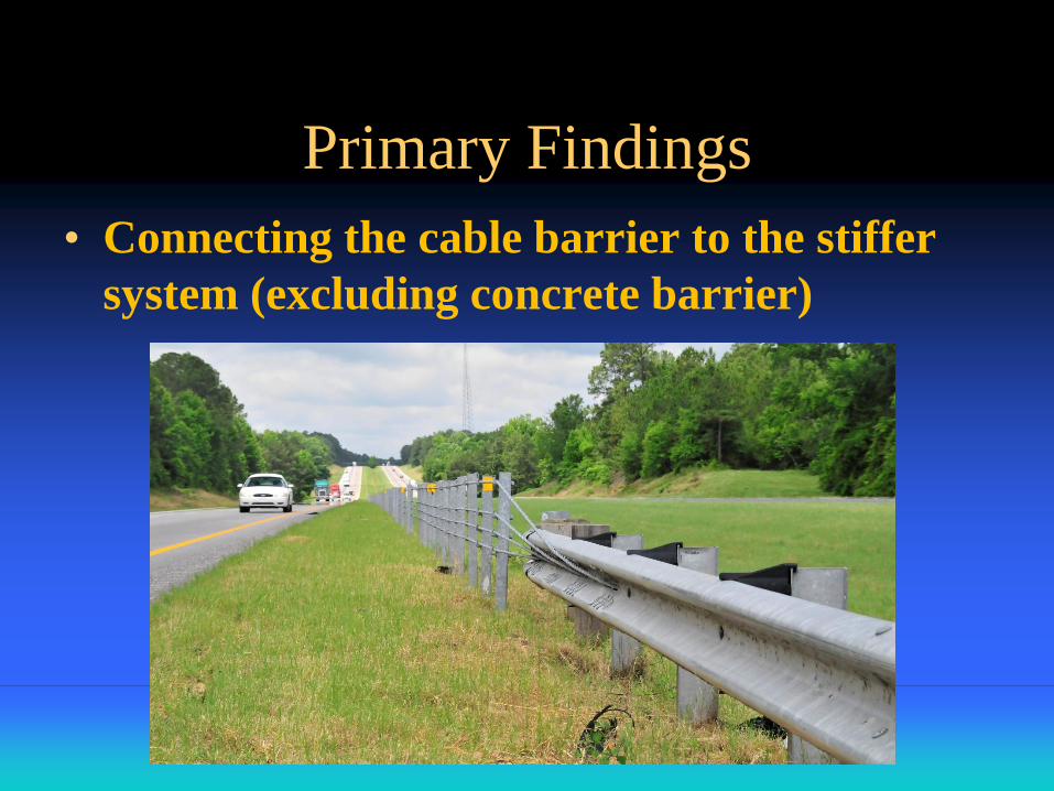
• Connecting the cable barrier to the stiffer
system (excluding concrete barrier)
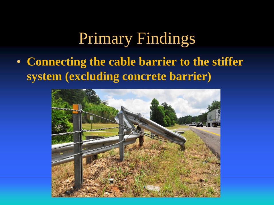
Primary Findings
• Connecting the cable barrier to the stiffer
system (excluding concrete barrier)
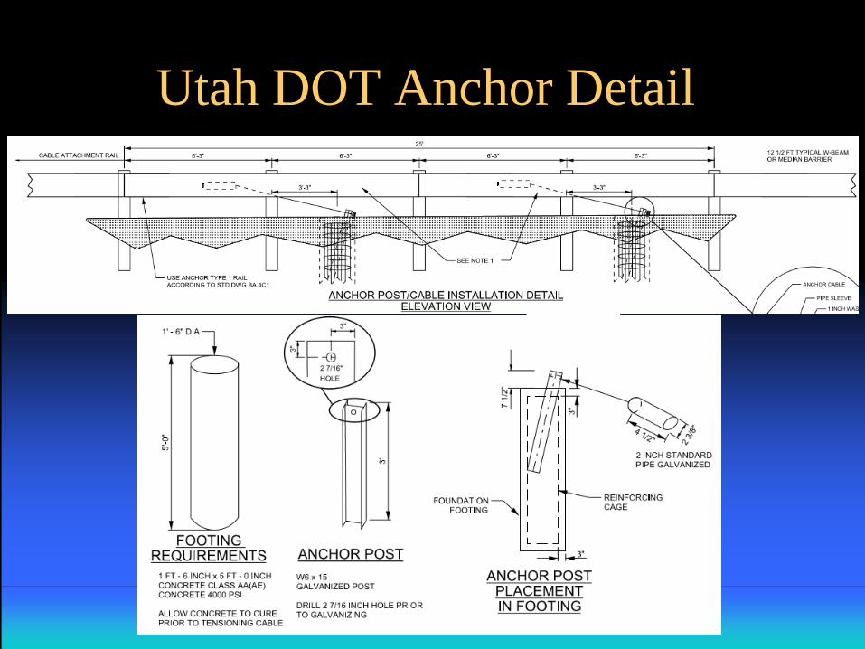
Utah DOT Anchor Detail
Example Specifications/Special Provisions
• Most of the states using HTCB have
developed specifications and/or special
provisions for these barriers
• Summary information from two states
representing both a geographical
distribution and the diversity of detail will
be presented
Rhode Island
Specifications for HTCB in Rhode Island
include the following items:
• Description of Work
• Materials
• Basis of Acceptance
• Construction Methods
• Measurement/Payment
Michigan
Michigan has, by far, the most comprehensive series
of Special Provisions addressing HTCB. In addition
to the “standard” items, these include:
• Manufacturers’ Representative
• Consultation and Training
• Geotechnical Information
• Concrete Foundation Construction
• Terminal Foundation Monitoring
Maintenance Concerns
Routine:
• check and record tension periodically
Crash-related:
• Cut cables only in an emergency situation
• Release tension by releasing end anchor or
releasing cables from several adjacent posts (some
systems)
• If no other choices, cut turnbuckles, not cables
themselves
Conclusions
The synthesis report contains a “shopping list” of
items for consideration in states’ specifications and
special provisions related to HTCB selection,
design, installation, and maintenance.
These items are not included in all states’
specifications or special provisions, but the listing
shown on the next slide is comprehensive.
• Description of work
• Materials
• Manufacturer’s representative
• Consultation and training
• Plans and shop drawings
• Geotechnical information
• General HTCB system design
• Concrete foundation construction
• HTCB construction and installation
• Cable terminal foundation monitoring
• Measurement and payment
Research Suggestions
In-service performance evaluations documenting
crash performance of each HTCB design, long-term
materials performance, and maintenance concerns
Revised test matrix and evaluation criteria allowing
comparison of different HTCB systems performance
on slopes

QUESTIONS?