Embed Size (px)
Citation preview
Pramod V. Bhagwat & S.Pramod V. Bhagwat & S. KailasKailas
Pelletron Accelerator FacilityPelletron Accelerator Facility
Nuclear Physics DivisionNuclear Physics Division
Bhabha Atomic Research CentreBhabha Atomic Research Centre
Mumbai, INDIAMumbai, INDIA

Introduction
A 5.5 MV Van-de-graaff single ended machine was commissioned in the sixties at BARC. This machine was utilized for various applications. In 1982, the project MEHIA started, where a 14 UD Pelletron Accelerator was purchased from M/s NEC, USA and installed at Tata Institute of Fundamental Research, Colaba, Mumbai. This accelerator was commissioned in 1988 and since then it has been serving as a major facility for heavy ion accelerator based research in India. In 1993, a project to convert 5.5 MV Van-de-Graaff to a 6 MV Folded machine was taken up. The first beam from was accelerated in 2000. The electron accelerators on the other hand, have wide industrial applications. The Electrons Beam Center has been set up at Kharghar, Mumbai, where 0.5 MeV, 3 MeV and 10 MeV electron accelerators are under construction. The 500 KeV electron beam accelerator is operational and being used for cable irradiation etc. The medical cyclotron was set up at Radiation Medicine Centre, Parel, Mumbai for Positron Emission Tomography
Development of AcceleratorsPelletron Accelerator Facility, BARC-TIFR
Folded Tandem Ion Accelerator, BARC
500 KeV, 10KW DC Electron Accelerator
3MeV, 30KW DC Electron Accelerator
10MeV, 10KW RF LINAC Accelerator
400KeV, Neutron(14MeV) Generator
16.5MeV, Medical Cyclotron at Radiation Medicine Centre

The Pelletron Accelerator facility set up as a collaborative project between BARC and TIFR, has been a major centre for heavy ion accelerator based research in India since its commissioning in 1989.Several major experimental facilities have been established at this centre to pursue research in nuclear physics, atomic physics andinterdisciplinary areas. While majority of users of this facility have been from the BARC and TIFR, it has been open to users from all over the country. These past years have been extremely productive resulting in 48 Ph.D. theses and over 300 publications in refereed international journals including 12 publications in Physical Review Letters. The Pelletron accelerator is presently being augmented with a superconducting LINAC booster comprising of seven modules, which will increase the energy of the presently available beams. For example, it will be possible to get beams in A~60 region with E~5 MeV/A.
Pelletron

Schematic
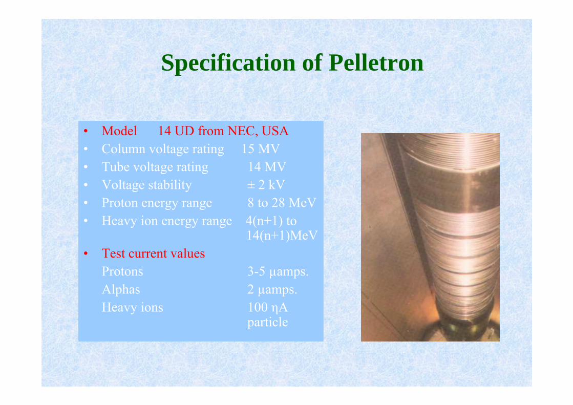
• Model 14 UD from NEC, USA• Column voltage rating 15 MV• Tube voltage rating 14 MV• Voltage stability ± 2 kV• Proton energy range 8 to 28 MeV• Heavy ion energy range 4(n+1) to
14(n+1)MeV• Test current values
Protons 3-5 µamps.Alphas 2 µamps.Heavy ions 100 ηA
particle
Specification of Pelletron

0
20
40
60
80
100
89 91 93 95 97 99
BreakdownMaintenanceConditioningUtilisation
Performance
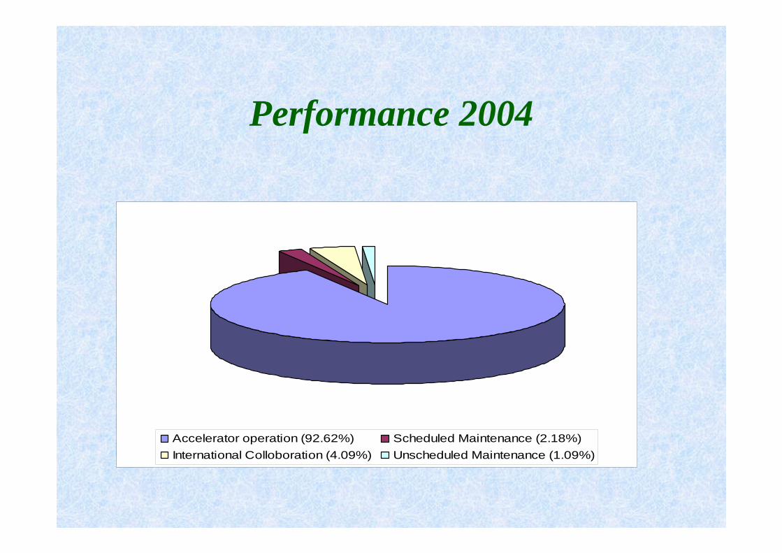
Performance 2004
Accelerator operation (92.62%) Scheduled Maintenance (2.18%)International Colloboration (4.09%) Unscheduled Maintenance (1.09%)

Ion Beam-2004
1H 6Li 7Li 10B 11B 12C13C 16O 19F 24Mg 28Si 32S35Cl 37Cl 58Ni 63Cu 107Ag

Beam Hall


Quarter Wave Resonator
Superconducting LINAC Booster for Pelletron

SUB SYSTEMS OF FOTIA
• HIGH VOLTAGE GENERATOR
• MAGNETS
• HIGH VOLTAGE & HIGH CURRENT SUPPLIES
• ULTRA HIGH VACUUM
• COMPUTER CONTROL SYSTEM
• SF6 GAS HANDLING SYSTEM ………

FOTIA

New ProjectA positive ion injector consisting of an ECR Ion Source followed by a Radio Frequency Quadrupole and Superconducting Niobium Cavities will be developed for further enhancing the available beam species and energies.

Schematic layout of the injector system
RFQ/ interdigitalstructure
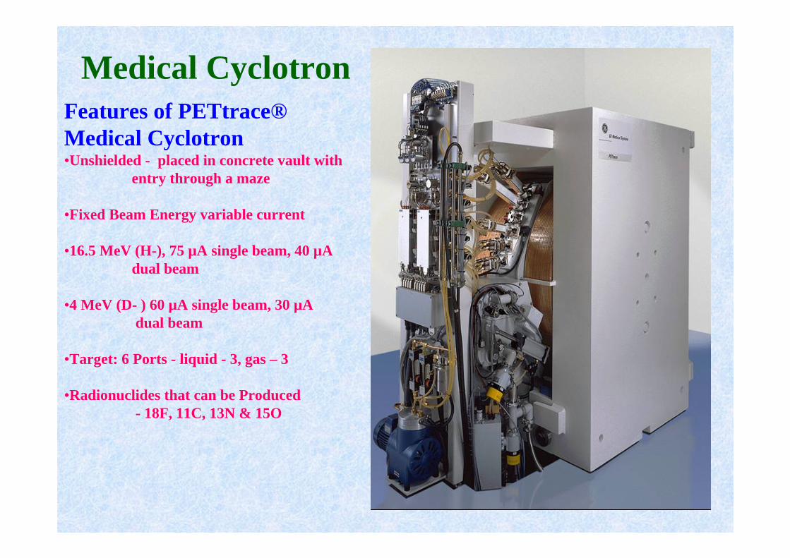
Medical CyclotronFeatures of PETtrace®Medical Cyclotron•Unshielded - placed in concrete vault with
entry through a maze
•Fixed Beam Energy variable current
•16.5 MeV (H-), 75 µA single beam, 40 µA dual beam
•4 MeV (D- ) 60 µA single beam, 30 µAdual beam
•Target: 6 Ports - liquid - 3, gas – 3
•Radionuclides that can be Produced- 18F, 11C, 13N & 15O
Accelerator Applications
Accelerator Mass Spectrometry(AMS)
Track-Etched Membrane
High Current Proton Irradiation Facility
Radiation Biology
Material Science
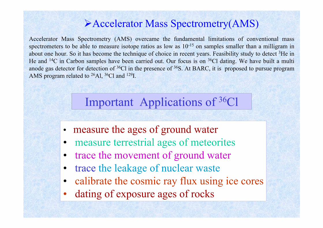
Accelerator Mass Spectrometry(AMS)Accelerator Mass Spectrometry (AMS) overcame the fundamental limitations of conventional mass spectrometers to be able to measure isotope ratios as low as 10-15 on samples smaller than a milligram in about one hour. So it has become the technique of choice in recent years. Feasibility study to detect 3He in He and 14C in Carbon samples have been carried out. Our focus is on 36Cl dating. We have built a multi anode gas detector for detection of 36Cl in the presence of 36S. At BARC, it is proposed to pursue program AMS program related to 26Al, 36Cl and 129I.
Important Applications of 36Cl
• measure the ages of ground water• measure terrestrial ages of meteorites• trace the movement of ground water• trace the leakage of nuclear waste• calibrate the cosmic ray flux using ice cores• dating of exposure ages of rocks
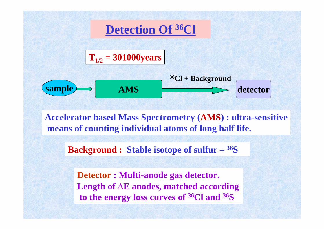
Detection Of 36Cl
Background : Stable isotope of sulfur – 36S
T1/2 = 301000years
sample AMS detector36Cl + Background
Accelerator based Mass Spectrometry (AMS) : ultra-sensitivemeans of counting individual atoms of long half life.
Detector : Multi-anode gas detector.Length of ∆E anodes, matched accordingto the energy loss curves of 36Cl and 36S
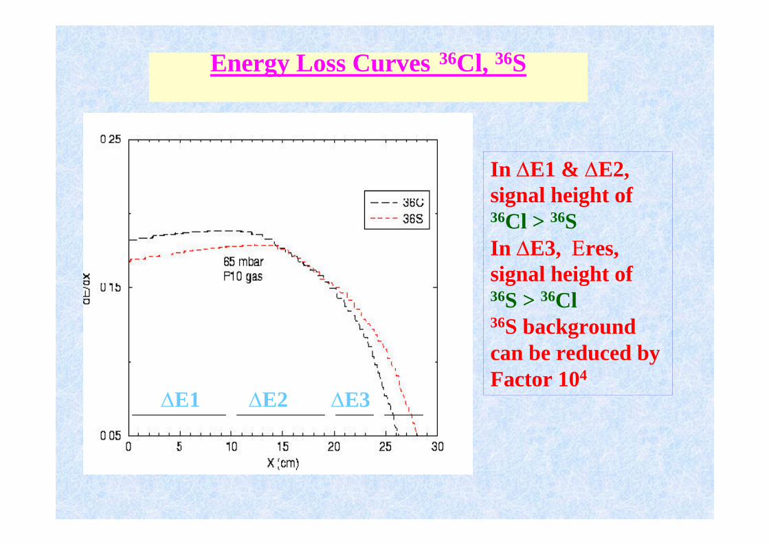
Energy Loss Curves 36Cl, 36S
In ∆E1 & ∆E2, signal height of36Cl > 36SIn ∆E3, Εres,signal height of36S > 36Cl36S backgroundcan be reduced by Factor 104
∆E1 ∆E2 ∆E3
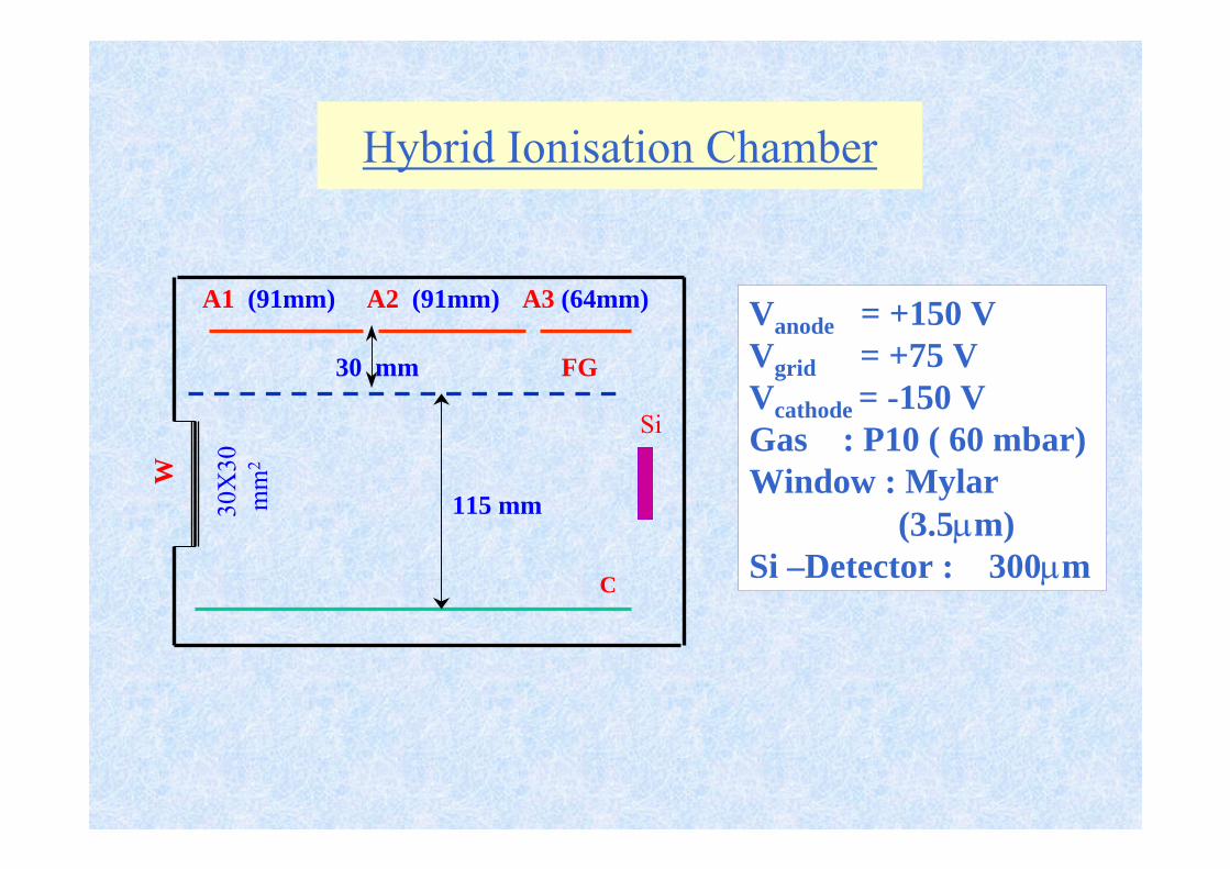
Hybrid Ionisation ChamberW
3 0X
30m
m2
A3 (64mm)A1 (91mm) A2 (91mm)
30 mm FG
C
115 mm
Si
Vanode = +150 V Vgrid = +75 VVcathode = -150 VGas : P10 ( 60 mbar)Window : Mylar
(3.5µm) Si –Detector : 300µm

Track-Etched Membrane
The technology of production of track-etched membranes (TEMs) using accelerated heavy ions has been well established. A beam scanner magnet, vacuum chamber, power supply and rolling mechanism have been developed indigenously. The membranes produced from this facility using variety of heavy ion beams (Ni, Cl, Ag etc) are used in medical science, analytical science and micro-filtration. An SEM photograph of track-etched membrane produced from this facility is shown in Fig 4. Efforts are underway to produce large size Track-etched membranes.

Track Membrane Set-Up
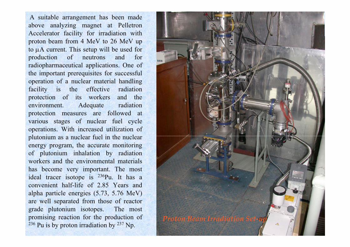
A suitable arrangement has been made above analyzing magnet at Pelletron Accelerator facility for irradiation with proton beam from 4 MeV to 26 MeV up to µA current. This setup will be used for production of neutrons and forradiopharmaceutical applications. One of the important prerequisites for successful operation of a nuclear material handling facility is the effective radiation protection of its workers and the environment. Adequate radiation protection measures are followed at various stages of nuclear fuel cycle operations. With increased utilization of plutonium as a nuclear fuel in the nuclear energy program, the accurate monitoring of plutonium inhalation by radiation workers and the environmental materials has become very important. The most ideal tracer isotope is 236Pu. It has a convenient half-life of 2.85 Years and alpha particle energies (5.73, 5.76 MeV) are well separated from those of reactor grade plutonium isotopes. The most promising reaction for the production of 236 Pu is by proton irradiation by 237 Np.

Thin layer activation technique for study of wear and tear of machine parts has been standardized using the reaction 56Fe(p,n)60Co. Proton beam at 16 MeV from Pelletron Accelerator was used for the production of 56Co into a stack of stainless steel foils to generate the calibration curve. This facility has been used for preparation of radiotracers.
Material Science
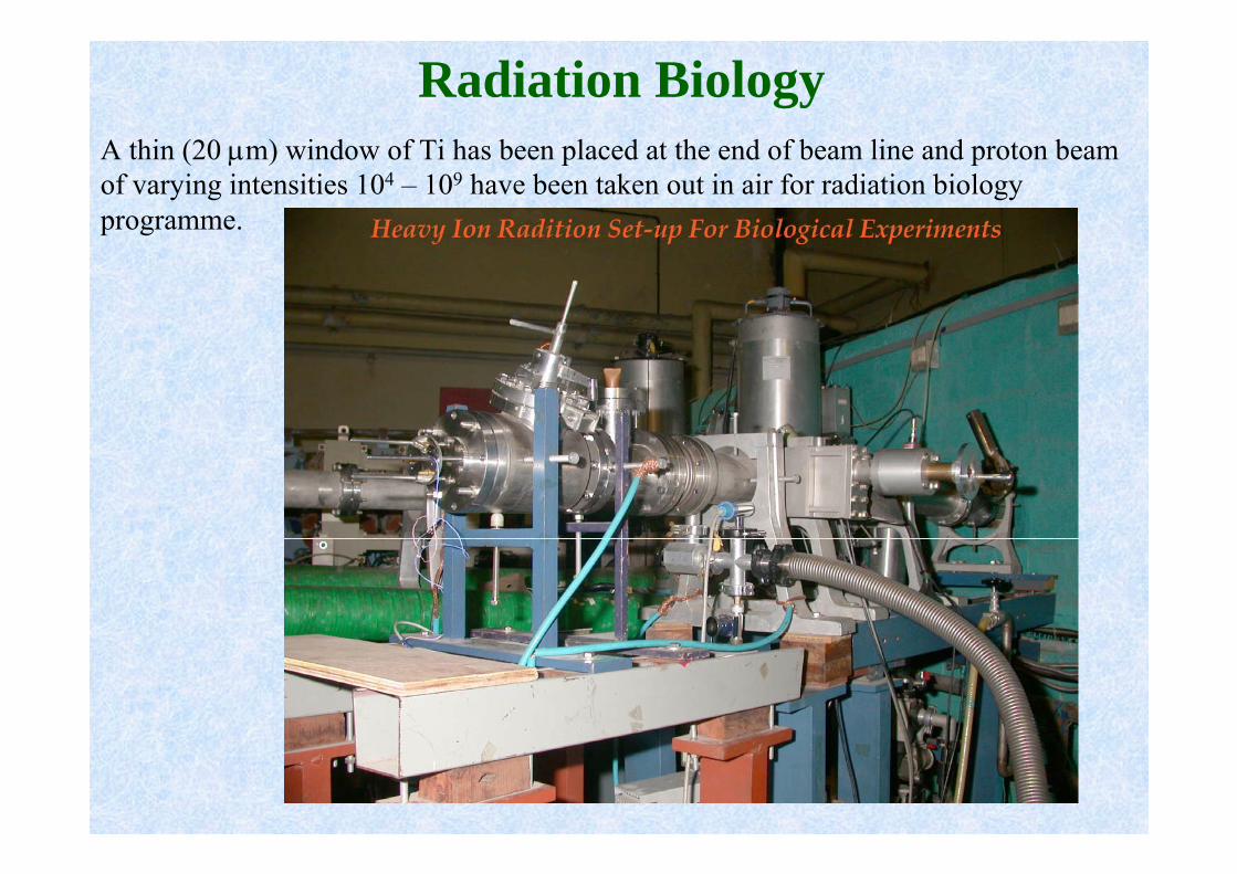
Radiation BiologyA thin (20 µm) window of Ti has been placed at the end of beam line and proton beam of varying intensities 104 – 109 have been taken out in air for radiation biologyprogramme.

Proteins and enzymes with transition metal ions at the active centersplay vital roles in life processes:High energy radiations can have different types of effects on these vital biomolecules:
Effect of highEffect of high--energy proton beams on energy proton beams on metal containing proteinsmetal containing proteins
400 500 6000.0
0.5
1.0
1.5
500 600
Abs
orba
nce
of C
ytoc
hrom
e c
λ (nm)
λ (nm)
400 500 6000.0
0.5
1.0
1.5
500 600Abso
rban
ce o
f Myo
glob
in
λ (nm)
λ (nm)
Iron Centre in Cytochrome c becomes Ferrous (Fe2+) from ferric ion (Fe3+) by the High Energy Proton Beams
Denaturation (Damage) of Myoglobin on irradiation by high energy proton beam

0 10 20 30 40 500.6
0.7
0.8
0.9
1.0N
orm
alis
ed A
bsor
banc
e at
406
nm
Time (Secs)
Cytochrome c
Myoglobin
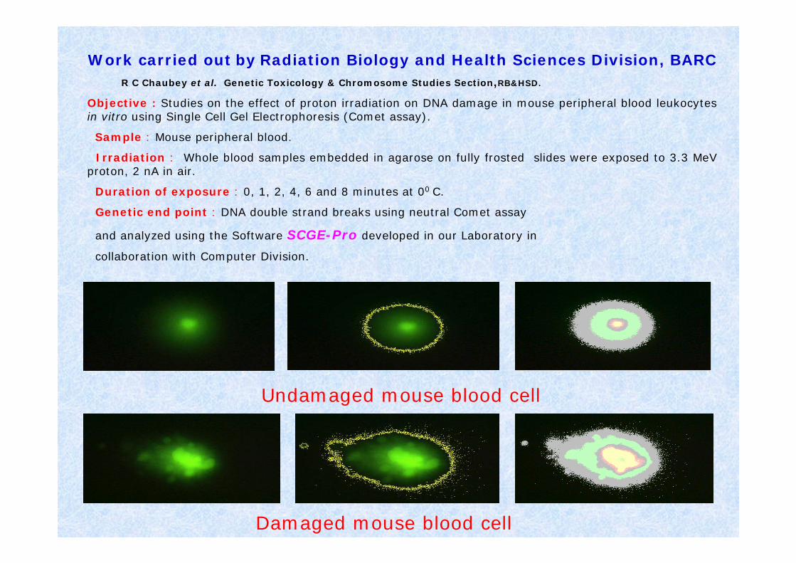
Undamaged mouse blood cell
Damaged mouse blood cell
Work carried out by Radiation Biology and Health Sciences Division, BARC
Objective : Studies on the effect of proton irradiation on DNA damage in mouse peripheral blood leukocytes in vitro using Single Cell Gel Electrophoresis (Comet assay).
Sample : Mouse peripheral blood.
Irradiation : Whole blood samples embedded in agarose on fully frosted slides were exposed to 3.3 MeV proton, 2 nA in air.
Duration of exposure : 0, 1, 2, 4, 6 and 8 minutes at 00 C.
Genetic end point : DNA double strand breaks using neutral Comet assay
and analyzed using the Software SCGE-Pro developed in our Laboratory in
collaboration with Computer Division.
R C Chaubey et al. Genetic Toxicology & Chromosome Studies Section,RB&HSD.

Radiation Induced Segregation (RIS) in SSRIS :
depletion of Cr at grain boundaries
segregation of Ni at grain boundaries
(Inverse Kirkendall Effect)
segregation of Si and P at grain boundaries
(Interstitial Association Mechanism )
Irradiation Assisted Stress Corrosion Cracking
IASCC occurs in SS after RIS induced by neutron fluence of
• 5 x 10²⁰ n/cm2 for SS 304
• 1 x 10²¹ n/cm2 for SS 316

As received SS 304 Thermally sensitized SS 304 e.g. after welding
Irradiated SS 304: 4.2 x 10¹⁶ protons/cm2
(0.2 dpa)Double loop EPR test result showing reactivation from irradiated SS 304
Irradiation damage measurement in irradiated SS 304: Proton irradiation in FOTIA and
electrochemical measurement of irradiation damage

APPROACHES TO BE FOLLOWED:
1. Control of Grain Boundary Nature• Twin grain boundaries/Special grain boundaries• Random grain boundaries
2. Heat Treatment to create initial segregation of Cr. This would retard the onset of RIS
3. Addition of oversized solute alloying elements like Ce, Hf, Zr, Gd, and Pt etc
Making SS Resistant to Irradiation Damage
• Neutron irradiation damage simulation by proton irradiation in FOTIA/Pelletron• Measurement of RIS by electrochemical techniques• Measurement of nature of grain boundaries by Orientation Imaging Microscopy• Measurement at individual grain boundary or a selected region by micro-electrochemical techniques
View of Tower and Lab- Block
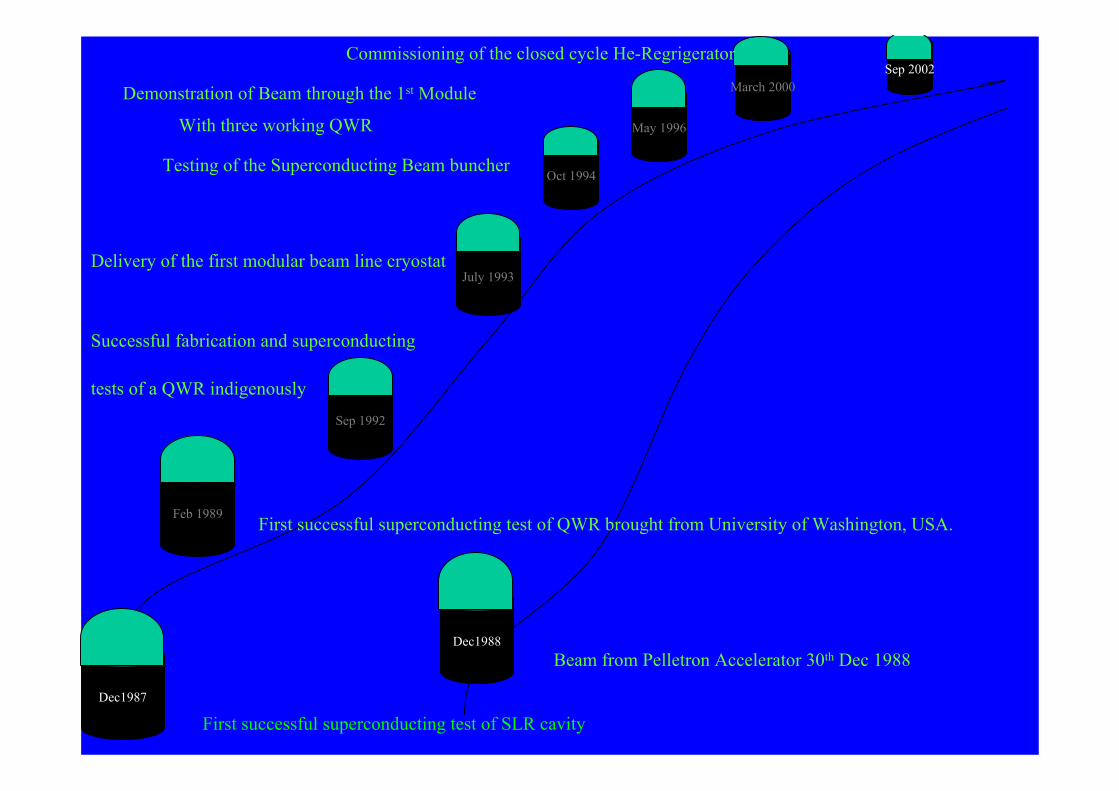
Sep 2002
3-Accelerating modules
Dec1988Beam from Pelletron Accelerator 30th Dec 1988
Feb 1989First successful superconducting test of QWR brought from University of Washington, USA.
Dec1987
First successful superconducting test of SLR cavity
Sep 1992
Successful fabrication and superconducting
tests of a QWR indigenously
July 1993Delivery of the first modular beam line cryostat
Oct 1994Testing of the Superconducting Beam buncher
May 1996With three working QWR
Demonstration of Beam through the 1st Module March 2000
Commissioning of the closed cycle He-Regrigerator
Beam Acceleration through

Offset Quadrupole


Charge Selector

• AN OVER VIEW OF EXPERIMENTAL SETUP FOR PIXE & RADIATION BIOLOGY STUDIES, SETUP ON 450 LINE AT FOTIA FACILITY.
• BEAM CAN BE EXTRACTED IN AIR FROM 20µ ΤΗΙCK TITANIUM WINDOW
• Si(Li) DETECTOR HOUSING WITH MILAR WINDOW.
• LOADLOCK MECHNISM FOR ONLINE TRANSFER OF TARGETS
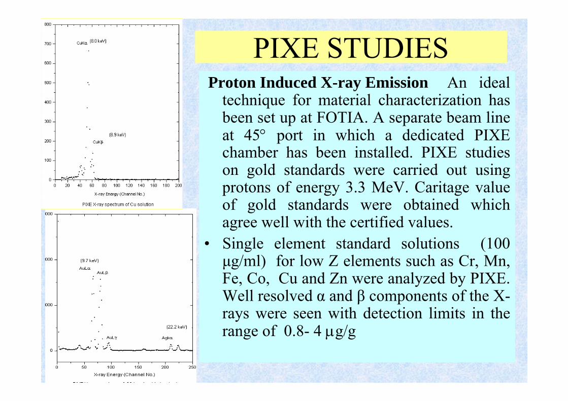
PIXE STUDIESProton Induced X-ray Emission An ideal
technique for material characterization has been set up at FOTIA. A separate beam line at 45° port in which a dedicated PIXE chamber has been installed. PIXE studies on gold standards were carried out using protons of energy 3.3 MeV. Caritage value of gold standards were obtained which agree well with the certified values.
• Single element standard solutions (100µg/ml) for low Z elements such as Cr, Mn, Fe, Co, Cu and Zn were analyzed by PIXE. Well resolved α and β components of the X-rays were seen with detection limits in the range of 0.8- 4 µg/g

BEAM LINES
1. Nuclear Physics
2. Accelerator Mass Spectrometry (AMS)
3. Trace Element Analysis ( RBS, PIXE, etc.)
4. Atomic Physics ( BFS)
5. Irradiation line


![COMPLETE PELLETRON SYSTEMS FOR ION BEAM ......National Electrostatics Corp. 7540 Graber Rd., P.O. Box 620310, Middleton, WI 53562-0310 USA 06/14 [IBA] COMPLETE PELLETRON SYSTEMS FOR](https://img.pdfslide.net/doc/110x75/5f218a320471711893037fe6/complete-pelletron-systems-for-ion-beam-national-electrostatics-corp-7540.jpg)