Embed Size (px)
Citation preview
NEYVELI LIGNITE CORPORATION LIMITED
PRE FEASIBILITY REPORT
2X500 MW SUB-CRITICAL LIGNITE BASED POWER PLANT AT MUDANAI DISTT. CUDDALORE,
TAMILNADU
APRIL 2016
DESEIN PRIVATE LIMITED CONSULTING ENGINEERS DESEIN
HOUSE, GREATER KAILASH-II NEW DELHI – 110 048

NEYVELI LIGNITE CORPORATION LIMITED
ISO 9001:2008 Registered Company Certificate No. 10692
CIN : U74899DL1970PTC005474
A D e v e l o p m e n t S e r v i c e f o r I n d u s t r i e s & U t i l i t i e s
INDEX
S.NO. DESCRIPITION SHEET NO.
PROJECT HIGHLIGHTS 01-02
1.0 INTRODUCTION 03-04
2.0 DEMAND ANALYSIS AND JUSTIFICATION 05-11
3.0 INFRASTRUCTURAL REQUIREMENTS 12-13
4.0 TECHNICAL FEATURES OF THE STEAM GENERATOR 14-22
5.0 DESCRIPTION OF BALANCE OF PLANT 23-91
5.1 MECHANICAL SYSTEM 23-51
5.2 ELECTRICAL SYSTEM & EQUIPMENT 52-76
5.3 CONTROL & INSTRUMENTATION 77-85
5.4 CIVIL & STRUCTURAL ENGINEERING ASPECTS 86-91
6.0 PLOT PLAN AND GENERAL ARRANGEMENT 92-94
7.0 ENVIRONMENTAL CONSIDERATIONS 95-97
8.0 EXECUTION AND MANAGEMENT 98
9.0 PROJECT COST 99
10.0 CONCLUSION 100

NEYVELI LIGNITE CORPORATION LIMITED
ISO 9001:2008 Registered Company Certificate No. 10692
CIN : U74899DL1970PTC005474
A D e v e l o p m e n t S e r v i c e f o r I n d u s t r i e s & U t i l i t i e s
LIST OF ANNEXURES
Sl. No. Annexure No. Description
1. 2.0 Location Map
2. 2.1 Raw Water Analysis Report
3. 2.2 Lignite Analysis Report
4. 4.1 Climatological Data
5. 5.0 Composite Water Scheme
6. 5.1 Flow Diagram for Pre Treatment Plant
7. 5.2 Flow Diagram for UF-RO-MB Plant
8. 5.3 Flow Diagram for Effluent Treatment Plant
9. 5.4 Flow Diagram for Bottom Ash Handling System
10. 5.5 Flow Diagram for Fly Ash Handling System
11. 5.6 Flow Diagram for External Lignite Handling System (ELHS) & Internal Lignite Handling System (ILHS)
12. 6.1 Plot Plan
13. 6.5 Key Single Line Diagram
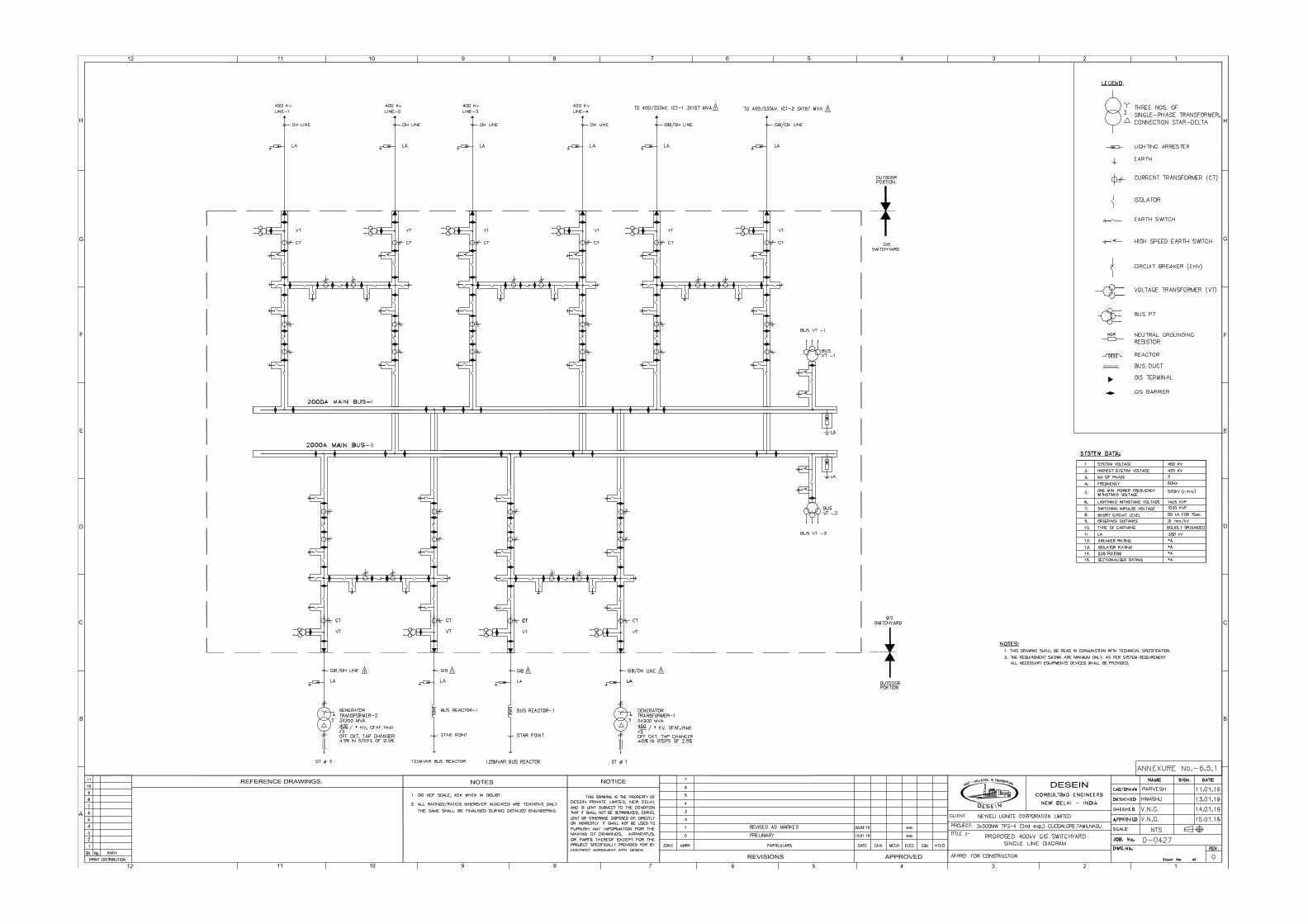
14. 6.5.1 400 KV GIS Switchyard SLD
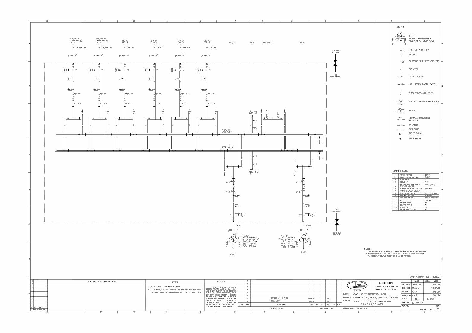
15. 6.5.2 230 KV GIS Switchyard SLD
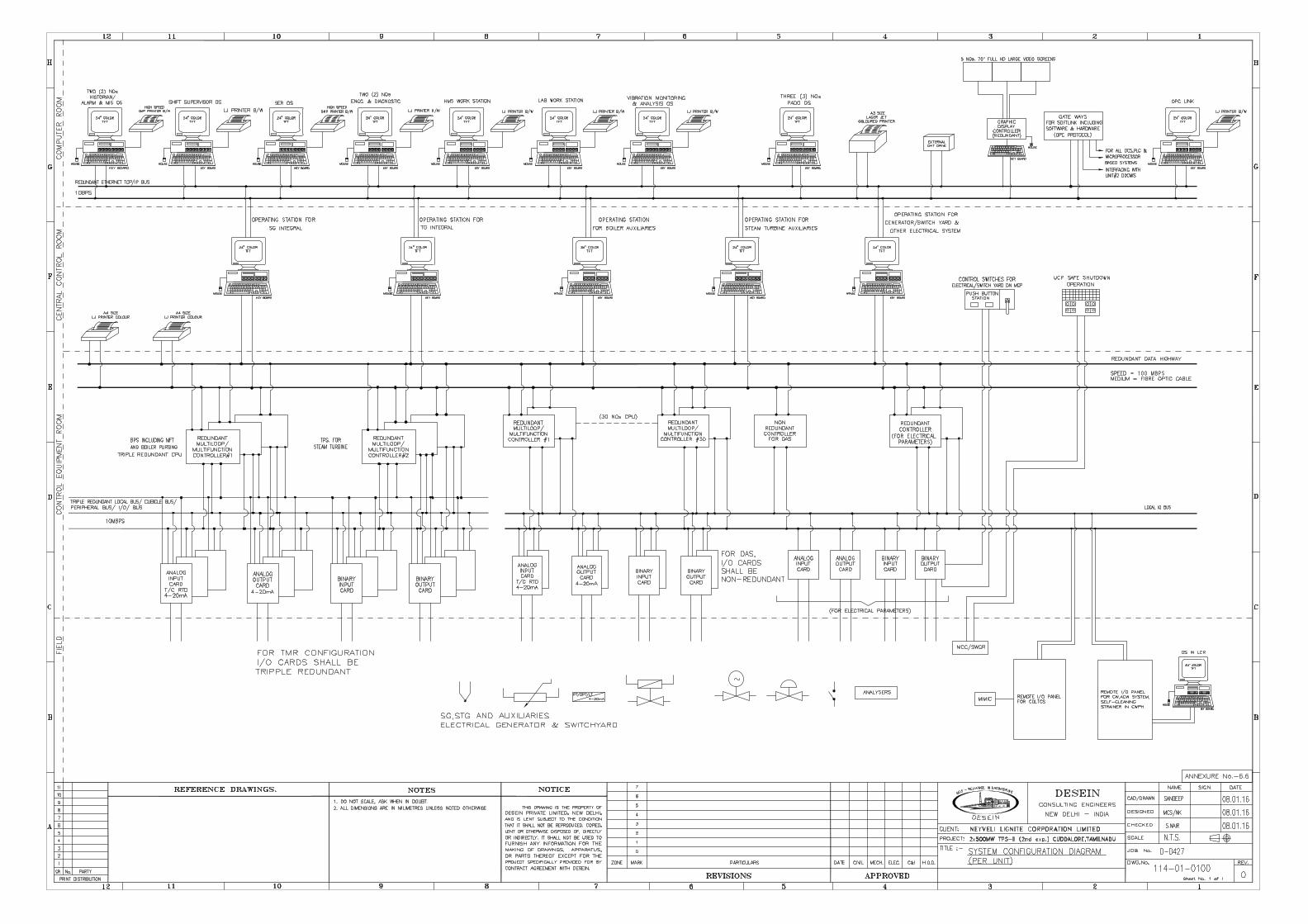
16. 6.6 System Configuration Diagram

NEYVELI LIGNITE CORPORATION LIMITED
Sheet - 1
ISO 9001:2008 Registered Company Certificate No. 10692
CIN : U74899DL1970PTC005474
A D e v e l o p m e n t S e r v i c e f o r I n d u s t r i e s & U t i l i t i e s
PROJECT HIGHLIGHTS
1. Project : 2x500 MW TPS at Mudanai
2. Promoters : Neyveli Lignite Corporation Limited
3. Plant Capacity : 1000 MW
4. Plant Configuration : 2 x 500 MW
5. Location : Mudanai; Village, Cuddalore, Tamilnadu
: Latitude : 11034’ N to 110 35’ N : Longitude : 79026’ E to 790 27’ E : Nearest Town : Virudhachalam : 15 km : Nearest National : NH – 45 C : 15 km
Highway : Nearest Railway Station : i. UthangaL Mangalam : 1.5 km
: ii. Neyveli : 4 km : Nearest Airports : a. Trichy : 150 km
: b. Chennai : 200 km : Nearest Sea Port : Cuddalore : 45 km 6. Site Elevation : Height : + 50m to + 57m MSL
7. Seismic Zone : Zone II as per IS:1893 - 2002
8. Source of Water (Distance from site)
: Ground water and storm water to be sourced from NLC’s Mine III
9 Water Requirement : 2814 m3/hr
10. Plant Cooling System : Closed cycle cooling system using Natural Draft Cooling Tower.
11. Primary Fuel & Source : Lignite will be sourced from NLC’s Lignite Mine III
12. Support Fuel & Source : HSD/LDO from nearest refinery/oil depots.
13. Lignite Fuel GCV : 2720 Kcal/kg
14. Lignite Fuel Requirement with Gross Station Heat Rate at 85% PLF
: 7.44 MTPA
15. Support fuel (LDO/HSD) : 11564 KL/Year @ 1ml/kwh
16. Transportation :
i. Lignite fuel : Lignite will be transported from NLC’s mines by belt conveyor system
ii. Support fuel : By Road Tankers / Indian Railway System
NEYVELI LIGNITE CORPORATION LIMITED
Sheet - 2
ISO 9001:2008 Registered Company Certificate No. 10692
CIN : U74899DL1970PTC005474
A D e v e l o p m e n t S e r v i c e f o r I n d u s t r i e s & U t i l i t i e s
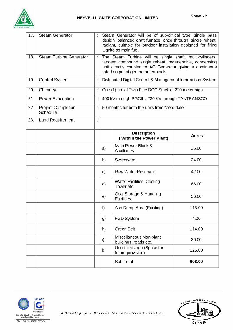
17. Steam Generator : Steam Generator will be of sub-critical type, single pass design, balanced draft furnace, once through, single reheat, radiant, suitable for outdoor installation designed for firing Lignite as main fuel.
18. Steam Turbine Generator : The Steam Turbine will be single shaft, multi-cylinders, tandem compound single reheat, regenerative, condensing unit directly coupled to AC Generator giving a continuous rated output at generator terminals.
19. Control System : Distributed Digital Control & Management Information System
20. Chimney : One (1) no. of Twin Flue RCC Stack of 220 meter high.
21. Power Evacuation : 400 kV through PGCIL / 230 KV through TANTRANSCO
22. Project Completion Schedule
: 50 months for both the units from “Zero date”.
23. Land Requirement :
Description
( Within the Power Plant) Acres
a) Main Power Block &
Auxiliaries 36.00
b) Switchyard 24.00
c) Raw Water Reservoir 42.00
d) Water Facilities, Cooling
Tower etc. 66.00
e) Coal Storage & Handling
Facilities. 56.00
f) Ash Dump Area (Existing) 115.00
g) FGD System 4.00
h) Green Belt 114.00
i) Miscellaneous Non-plant buildings, roads etc. 26.00
j) Unutilized area (Space for future provision) 125.00
Sub Total 608.00
NEYVELI LIGNITE CORPORATION LIMITED
Sheet - 3
ISO 9001:2008 Registered Company Certificate No. 10692
CIN : U74899DL1970PTC005474
A D e v e l o p m e n t S e r v i c e f o r I n d u s t r i e s & U t i l i t i e s
1.0 INTRODUCTION
Neyveli Lignite Corporation Limited (NLC), a Navratna Government of India
Enterprise, is engaged in Lignite Mining and Power Generation. As of September
2015, NLC’s total installed capacity is 4263.5 MW spread across six coal and
lignite based TPP’s. These are the 600 MW TPS-I, the 420 MW TPS-I
Expansion, the 1470 MW TPS-II, the 250 MW Barsingsar TPS, the 500MW TPS-
II Expansion, the 1000 MW Tuticorin TPS-a joint venture between NLC Limited
and Tamil Nadu Electricity Board, the Wind Farms 13.5 MW and the Solar 10
MW and operates four Mines of total capacity 30.6 Million Tonnes per annum
(MTPA).
The Lignite based New Neyveli Thermal Power Station (NNTPS) of 2 X 500 MW
capacity project at Neyveli, Bithnok TPS (1X250MW) linked with Bithnok Mine
(2.25MTPA) and Barsingsar TPS Extension (2X500 MW) linked with Hadla Mine
(9 MTPA) are under execution.
In the Non-Conventional Energy Sector, a 51 MW wind power project is under
implementation stage and in Neyveli a 10 MW Solar Power Project has been
Commissioned while another 130 MW at Neyveli and 130 MW Solar Power
Project at Barsingsar is under planning stages with more solar power plants in
other states of India are under formulation stages.
NLC Limited has proposals for rapid growth in power generation capacity and is
expanding its activities not only at Neyveli, but also in other parts of the country.
NLC has signed a JV agreement with UP Government to establish a 1980 MW
Power Station (3 x 660MW) at Ghatampur, Uttar Pradesh and the project is
moving fast into the execution phase. NLC has proposal to establish a power
plant with a final capacity of 4000 MW in two phases with 2000 MW in phase I
and the balance in phase II at Sirkali Tamil Nadu. Thermal Power Station II (2nd
expansion) of capacity 2 x 500 MW linked with Mine-III (9.0 MTPA) is under
conceptual stage.
NEYVELI LIGNITE CORPORATION LIMITED
Sheet - 4
ISO 9001:2008 Registered Company Certificate No. 10692
CIN : U74899DL1970PTC005474
A D e v e l o p m e n t S e r v i c e f o r I n d u s t r i e s & U t i l i t i e s
The company is also contemplating to increase its generation areas by means of
coal/lignite based power projects in India. NLC with its excellent performance,
figures among the top profit making Public Sector Undertaking.
To meet the growing demand of electricity, Neyveli Lignite Corporation Limited
(NLC) is planning to develop 2 x 500 MW Sub-critical Thermal Power Station
Project at Mudanai Village, Cuddalore, Tamilnadu.
In this direction, M/s NLC has engaged M/s DESEIN PRIVATE LIMITED,
Consulting Engineers for the preparation of Feasibility Report of 2 x 500 MW Sub-
critical Thermal Power Station. This Report is based on Central Electricity Authority
(CEA) guidelines, State Electricity Regulatory Commission (SERC) norms and
MoEF for basic EIA.
The Feasibility Report is prepared based on Govt. of India guidelines and CERC
norms. The scope covers the following:-
a) Capacity and size of the unit(s).
b) Location of the plant – layout plans.
c) Basic plant requirements, e.g., land, fuel, water etc.
d) Source and availability of fuel, land and water.
e) Description of salient features of mechanical and electrical equipment and
auxiliary systems; design consideration for civil and structural engineering
work.
f) Power Evacuation facilities.
g) Consideration of environmental aspects (the work would, however, not cover
EIA study as required by the Ministry of Environment & Forests).
h) Cost estimates up to the station bus including break-up under major heads
and phased expenditure in line with GOI guidelines based on the major
inputs received from NLC.
i) Financial analysis / estimated cost of generation as per the GOI norms and
as acceptable to F.Is. / Banks.
j) Time schedule for project implementation. k) Execution and management.
NEYVELI LIGNITE CORPORATION LIMITED
Sheet - 5
ISO 9001:2008 Registered Company Certificate No. 10692
CIN : U74899DL1970PTC005474
A D e v e l o p m e n t S e r v i c e f o r I n d u s t r i e s & U t i l i t i e s
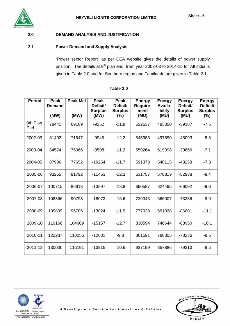
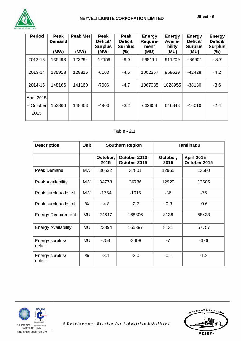
2.0 DEMAND ANALYSIS AND JUSTIFICATION
2.1 Power Demand and Supply Analysis
“Power sector Report” as per CEA website gives the details of power supply
position. The details at 9th plan end, from year 2002-03 to 2014-15 for All India is
given in Table 2.0 and for Southern region and Tamilnadu are given in Table 2.1.
Table 2.0
Period Peak Demand
(MW)
Peak Met
(MW)
Peak Deficit/ Surplus
(MW)
Peak Deficit/ Surplus
(%)
Energy Require-
ment (MU)
Energy Availa-bility (MU)
Energy Deficit/ Surplus
(MU)
Energy Deficit/ Surplus
(%)
9th Plan End
78441 69189 -9252 -11.8 522537 483350 -39187 -7.5
2002-03 81492 71547 -9945 -12.2 545983 497890 -48093 -8.8
2003-04 84574 75066 -9508 -11.2 559264 519398 -39866 -7.1
2004-05 87906 77652 -10254 -11.7 591373 548115 -43258 -7.3
2005-06 93255 81792 -11463 -12.3 631757 578819 -52938 -8.4
2006-07 100715 86818 -13897 -13.8 690587 624495 -66092 -9.6
2007-08 108866 90793 -18073 -16.6 739343 666007 -73336 -9.9
2008-09 109809 96785 -13024 -11.9 777039 691038 -86001 -11.1
2009-10 119166 104009 -15157 -12.7 830594 746644 -83950 -10.1
2010-11 122287 110256 -12031 -9.8 861591 788355 -73236 -8.5
2011-12 130006 116191 -13815 -10.6 937199 857886 -79313 -8.5
NEYVELI LIGNITE CORPORATION LIMITED
Sheet - 6
ISO 9001:2008 Registered Company Certificate No. 10692
CIN : U74899DL1970PTC005474
A D e v e l o p m e n t S e r v i c e f o r I n d u s t r i e s & U t i l i t i e s
Period Peak Demand
(MW)
Peak Met
(MW)
Peak Deficit/ Surplus
(MW)
Peak Deficit/ Surplus
(%)
Energy Require-
ment (MU)
Energy Availa-bility (MU)
Energy Deficit/ Surplus
(MU)
Energy Deficit/ Surplus
(%)
2012-13 135493 123294 -12159 -9.0 998114 911209 - 86904 - 8.7
2013-14 135918 129815 -6103 -4.5 1002257 959629 -42428 -4.2
2014-15 148166 141160 -7006 -4.7 1067085 1028955 -38130 -3.6
April 2015
– October
2015
153366 148463 -4903 -3.2 662853 646843 -16010 -2.4
Table - 2.1
Description Unit Southern Region Tamilnadu
October, 2015
October 2010 – October 2015
October, 2015
April 2015 – October 2015
Peak Demand MW 36532 37801 12965 13580
Peak Availability MW 34778 36786 12929 13505
Peak surplus/ deficit MW -1754 -1015 -36 -75
Peak surplus/ deficit % -4.8 -2.7 -0.3 -0.6
Energy Requirement MU 24647 168806 8138 58433
Energy Availability MU 23894 165397 8131 57757
Energy surplus/ deficit
MU -753 -3409 -7 -676
Energy surplus/ deficit
% -3.1 -2.0 -0.1 -1.2
NEYVELI LIGNITE CORPORATION LIMITED
Sheet - 7
ISO 9001:2008 Registered Company Certificate No. 10692
CIN : U74899DL1970PTC005474
A D e v e l o p m e n t S e r v i c e f o r I n d u s t r i e s & U t i l i t i e s
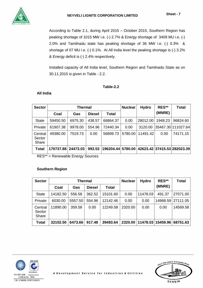
According to Table 2.1, during April 2015 – October 2015, Southern Region has
peaking shortage of 1015 MW i.e. (-) 2.7% & Energy shortage of 3409 MU i.e. (-)
2.0% and Tamilnadu state has peaking shortage of 36 MW i.e. (-) 0.3% &
shortage of 07 MU i.e. (-) 0.1%. At All India level the peaking shortage is (-) 3.2%
& Energy deficit is (-) 2.4% respectively.
Installed capacity of All India level, Southern Region and Tamilnadu State as on
30.11.2015 is given in Table - 2.2.
Table-2.2 All India
Sector Thermal Nuclear Hydro RES** (MNRE)
Total Coal Gas Diesel Total
State 59450.50 6975.30 438.57 66864.37 0.00 28012.00 1948.23 96824.60
Private 61907.38 9978.00 554.96 72440.34 0.00 3120.00 35467.30 111027.64
Central Sector Share
49380.00 7519.73 0.00 56899.73 5780.00 11491.42 0.00 74171.15
Total 170737.88 24473.03 993.53 196204.44 5780.00 42623.42 37415.53 282023.39
RES** = Renewable Energy Sources
Southern Region
Sector Thermal Nuclear Hydro RES**
(MNRE) Total
Coal Gas Diesel Total
State 14182.50 556.58 362.52 15101.60 0.00 11478.03 491.37 27071.00
Private 6030.00 5557.50 554.96 12142.46 0.00 0.00 14968.59 27111.05
Central Sector Share
11890.00 359.58 0.00 12249.58 2320.00 0.00 0.00 14569.58
Total 32102.50 6473.66 917.48 39493.64 2320.00 11478.03 15459.96 68751.63
NEYVELI LIGNITE CORPORATION LIMITED
Sheet - 8
ISO 9001:2008 Registered Company Certificate No. 10692
CIN : U74899DL1970PTC005474
A D e v e l o p m e n t S e r v i c e f o r I n d u s t r i e s & U t i l i t i e s
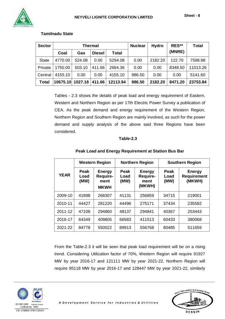
Tamilnadu State
Sector Thermal Nuclear Hydro RES** (MNRE)
Total Coal Gas Diesel Total
State 4770.00 524.08 0.00 5294.08 0.00 2182.20 122.70 7598.98
Private 1750.00 503.10 411.66 2664.36 0.00 0.00 8348.50 11013.26
Central 4155.10 0.00 0.00 4155.10 986.50 0.00 0.00 5141.60
Total 10675.10 1027.18 411.66 12113.94 986.50 2182.20 8471.20 23753.84
Tables - 2.3 shows the details of peak load and energy requirement of Eastern,
Western and Northern Region as per 17th Electric Power Survey a publication of
CEA. As the peak demand and energy requirement of the Western Region,
Northern Region and Southern Region are mainly involved, as such for the power
demand and supply analysis of the above said three Regions have been
considered.
Table-2.3
Peak Load and Energy Requirement at Station Bus Bar
YEAR
Western Region Northern Region Southern Region
Peak Load (MW)
Energy Require-
ment MKWH
Peak Load (MW)
Energy Require-
ment (MKWH)
Peak Load (MW)
Energy Requirement
(MKWH)
2009-10 41898 268307 41131 256859 34715 219001
2010-11 44427 281220 44496 275171 37434 235582
2011-12 47108 294860 48137 294841 40367 253443
2016-17 64349 409805 66583 411513 60433 380068
2021-22 84778 550022 89913 556768 80485 511659
From the Table-2.3 it will be seen that peak load requirement will be on a rising
trend. Considering Utilization factor of 70%, Western Region will require 91927
MW by year 2016-17 and 121111 MW by year 2021-22, Northern Region will
require 95118 MW by year 2016-17 and 128447 MW by year 2021-22, similarly
NEYVELI LIGNITE CORPORATION LIMITED
Sheet - 9
ISO 9001:2008 Registered Company Certificate No. 10692
CIN : U74899DL1970PTC005474
A D e v e l o p m e n t S e r v i c e f o r I n d u s t r i e s & U t i l i t i e s
Southern region will require 86333 MW by year 2016-17 and 114979 MW by
2021-22.
To bridge the gap between demand and supply, generation of additional capacity is
required. The proposed project has been considered for the effective utilization of
existing infrastructure and water. Further, the proposed TPS will have the advantage
of economy of scale in reducing the cost of generation by adopting Sub-critical
Technology.
2.2 Government Policy for Power Generation/Requirement of Input/ Clearance Liberalization policy of Govt. of India in power generation by the enactment of
Electricity Act 2003 has come in force. The Act consolidates the laws relating to
generation transmission, distribution, trading, and use of electricity and generally
for taking measures conducive to development of electricity industry, promoting
competition therein, protecting interest of consumers and supply of electricity to
all areas, rationalization of electricity tariff, ensuring transparent policies regarding
subsidies, promotion of efficient and environmentally benign policies etc.
As per Clause-7 of the Act 2003 “Any Generating Company may establish,
operate and maintain generating station without obtaining license under this Act if
it complies with technical standards relating to connectivity with the grid”.
M/s NLC being a generating company is logically in the right direction to install the
proposed project.
2.2.1 Requirement of Input/Clearances Electricity Act 2003 do not indicate special requirement like clearances from the
concerned statutory or non-statutory authorities for setting up thermal power
plant. However, clause 10 (3) stipulates that generating company will:
a) Submit technical details regarding its generating station to appropriate
commission (i.e. CERC/SERC) and the Authority (i.e. CEA).
b) Co-ordinate with Central Transmission Utility or State Transmission
Utility as the case may be for transmission of electricity generated by it.
NEYVELI LIGNITE CORPORATION LIMITED
Sheet - 10
ISO 9001:2008 Registered Company Certificate No. 10692
CIN : U74899DL1970PTC005474
A D e v e l o p m e n t S e r v i c e f o r I n d u s t r i e s & U t i l i t i e s
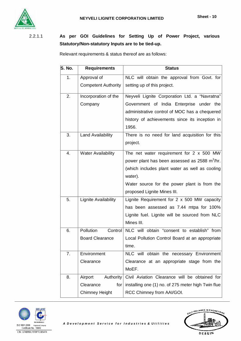
2.2.1.1 As per GOI Guidelines for Setting Up of Power Project, various Statutory/Non-statutory Inputs are to be tied-up.
Relevant requirements & status thereof are as follows:
S. No. Requirements Status
1. Approval of
Competent Authority
NLC will obtain the approval from Govt. for
setting up of this project.
2. Incorporation of the
Company
Neyveli Lignite Corporation Ltd. a “Navratna”
Government of India Enterprise under the
administrative control of MOC has a chequered
history of achievements since its inception in
1956.
3. Land Availability
There is no need for land acquisition for this
project.
4. Water Availability The net water requirement for 2 x 500 MW
power plant has been assessed as 2588 m3/hr.
(which includes plant water as well as cooling
water).
Water source for the power plant is from the
proposed Lignite Mines III.
5. Lignite Availability Lignite Requirement for 2 x 500 MW capacity
has been assessed as 7.44 mtpa for 100%
Lignite fuel. Lignite will be sourced from NLC
Mines III.
6. Pollution Control
Board Clearance
NLC will obtain “consent to establish” from
Local Pollution Control Board at an appropriate
time.
7. Environment
Clearance
NLC will obtain the necessary Environment
Clearance at an appropriate stage from the
MoEF.
8. Airport Authority
Clearance for
Chimney Height
Civil Aviation Clearance will be obtained for
installing one (1) no. of 275 meter high Twin flue
RCC Chimney from AAI/GOI.
NEYVELI LIGNITE CORPORATION LIMITED
Sheet - 11
ISO 9001:2008 Registered Company Certificate No. 10692
CIN : U74899DL1970PTC005474
A D e v e l o p m e n t S e r v i c e f o r I n d u s t r i e s & U t i l i t i e s
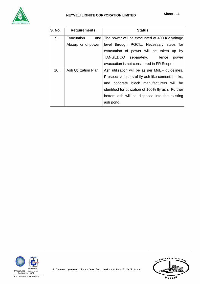
S. No. Requirements Status
9. Evacuation and
Absorption of power
The power will be evacuated at 400 KV voltage
level through PGCIL. Necessary steps for
evacuation of power will be taken up by
TANGEDCO separately. Hence power
evacuation is not considered in FR Scope.
10. Ash Utilization Plan Ash utilization will be as per MoEF guidelines.
Prospective users of fly ash like cement, bricks,
and concrete block manufacturers will be
identified for utilization of 100% fly ash. Further
bottom ash will be disposed into the existing
ash pond.
NEYVELI LIGNITE CORPORATION LIMITED
Sheet - 12
ISO 9001:2008 Registered Company Certificate No. 10692
CIN : U74899DL1970PTC005474
A D e v e l o p m e n t S e r v i c e f o r I n d u s t r i e s & U t i l i t i e s
3.0 INFRASTRUCTURAL REQUIREMENTS
3.1 Site Selection and Features of the Selected Site
For the establishment of a power project a number of basic inputs such as land,
fuel, water etc. are required. Location of power station is primarily governed by
the following basic considerations:-
a) Availability of land
b) Rail/road accessibility
c) Availability of fuel and its transportation
d) Availability of water and proximity to source
e) Proximity to the grid for evacuation of power
f) Environmental considerations
The most important criteria for selection of sites for Power Project is the
availability of land with least Resettlement and Rehabilitation (R&R) issues,
Fuel availability and its transportation, water availability and the acceptability from
the environmental considerations.
A team of officials from M/s NLC and M/s Desein visited the Mudanai Site and
examined the plant areas available for the proposed power plant.
It is about 1.5 km from Uthangal Mangalam & 4 km from Neyveli, Tamilnadu.
The nearest railway station is around 1.5 km at Uthangal Mangalam. The
nearest airport is around 150 km at Trichy. The Latitude and Longitude of the
proposed site are 11°34’ N and 79°26’ E respectively.
a) Land
The site is plane leveled land. The altitude from mean sea level is
approximately 6 m.
b) Rail/Road Accessibility
The site is well connected by NH-45C at a distance of 15 Km.
NEYVELI LIGNITE CORPORATION LIMITED
Sheet - 13
ISO 9001:2008 Registered Company Certificate No. 10692
CIN : U74899DL1970PTC005474
A D e v e l o p m e n t S e r v i c e f o r I n d u s t r i e s & U t i l i t i e s
The nearest railway station is at Virudhachalam which is about 4 km from
the site.
c) Lignite Fuel Availability & Transportation
The source of lignite fuel will be from NLC Mines III allocated by Ministry
of Coal.
d) Availability of Water
Ground water & storm water to be pumped from NLC Mines III for the
project.
e) Power Evacuation
Power generated from proposed plant will be evacuated at 400 kV
voltage level.
f) Environmental Aspects
As per observations made at the site, there are urban habitation in
the near vicinity. However, based on ToR to be obtained from MoEF, a
REIA study will be conducted and the necessary recommendation will
have to be taken care while implementing the project.
NEYVELI LIGNITE CORPORATION LIMITED
Sheet - 14
ISO 9001:2008 Registered Company Certificate No. 10692
CIN : U74899DL1970PTC005474
A D e v e l o p m e n t S e r v i c e f o r I n d u s t r i e s & U t i l i t i e s
4.0 TECHNICAL FEATURES OF THE STEAM GENERATOR 4.1 Steam Generator and Auxiliaries
The steam generator (SG) would be of sub critical parameters and designed for
firing 100% lignite fuel available from the existing Neyveli Mines III. The SG
would be of once through type, single pass design, radiant, single reheat,
balanced draft, semi-outdoor tower type rated to deliver 1540 t/hr of superheated
steam at 173 ksc (a), 540ºC with feed water temperature of about 276ºC at the
economizer inlet. The reheat steam temperature would be of 567ºC.
The SG would be designed to handle and burn heavy furnace oil (HFO) as
secondary fuel up to 30 % SG MCR (maximum continuous rating) capacity for
flame stabilization during low-load operation. For unit light up and warm up
purposes, light diesel oil (LDO) would be used with air atomization. The LDO
system capacity would be equal to 7.5 % SG MCR.
Steam and water system will essentially comprise of steam separator,
evaporator, down comers, water walls, superheater, reheater, de-superheater,
economizer, associated valves, fittings, piping, insulation, supporting hangers,
instrumentation etc.
The steam generator would consist of water cooled furnace, radiant and
convection super-heaters, re-heater, attemperators, economiser, regenerative air
heaters, steam coil air pre-heaters, etc. Soot blowers and water lancers would
be provided at strategic locations and would be designed for sequential fully
automatic operation from the unit control room.
The high volatile matter and high moisture present in lignite calls for milling and
firing system different from that employed for bituminous coal firing. The high
proportion of water vapour released causes an increase in the gas flow after the
mills and calls for special mills for lignite. Beater wheel type of mills with
classifiers would be provided.
NEYVELI LIGNITE CORPORATION LIMITED
Sheet - 15
ISO 9001:2008 Registered Company Certificate No. 10692
CIN : U74899DL1970PTC005474
A D e v e l o p m e n t S e r v i c e f o r I n d u s t r i e s & U t i l i t i e s
The lignite is fed from bunker on to Apron type feeder. Due to high moisture the
bunkers would be provided with multiple outlets. From the plate belt feeder, the
lignite is fed into the mills through a belt conveyor. For drying the lignite flue gas
is tapped from the furnace at about 1000ºC through re suction duct of the mills.
For grinding and transporting the lignite, high speed beater wheel mills running at
a speed of 600 rpm would be employed. Since the mill itself functions as fan
cum pulverizer having limited pressure capacity, these mills are located around
steam generator. The number of mills would be so chosen that the BMCR rating
would be met while firing the worst lignite with one mill stand by and the
maximum continuous rating of 500 MW (TMCR) would be obtained for design
lignite with 2 mills as standby.
All the mills working at 80% of their rated capacity would also meet the fuel
requirements of the steam generator at BMCR rating while firing the worst lignite.
The lignite burning system would be designed to achieve optimum combustion
with a maximum of 20% to 25% excess air. Each of the beater wheel mills
supplies pulverized lignite to one group of burners which consists of two or more
elevations of burners located one above the other.
The required fuel oil pressurizing units and fuel oil heating equipment would be
provided. High-energy electric arc igniters would be provided to ignite the fuel oil
guns. Features to prevent possible slagging if any and suitable de-slagging
devices will be contemplated.
The draft plant for the steam generator will be capable of maintaining balanced
draft condition in the furnace over the entire load range. The steam generators
will be supplied with a complete set of draft equipment including, forced draft fan,
induced draft fan, seal/cooling air fan, damper and associated equipment. Two
(2) nos. of 60% FD fan & ID fan will be provided. The FD fan & ID fans are sized
in such a way that each FD & ID fan will be able to cater the steam generator
requirements when operating at 60% BMCR. FD fans will be of Radial / Axial
blade pitch controlled type. ID fans will be of Radial / Axial frequency controlled
type. For each FD & ID fans forced oil lubrication system is provided, which will
consists of lube oil pumps, oil cooler, oil reservoirs, piping, valves, duplex strainer
NEYVELI LIGNITE CORPORATION LIMITED
Sheet - 16
ISO 9001:2008 Registered Company Certificate No. 10692
CIN : U74899DL1970PTC005474
A D e v e l o p m e n t S e r v i c e f o r I n d u s t r i e s & U t i l i t i e s
etc. All necessary regulating and isolating dampers will be provided for each fan
for safe & efficient operation.
Unburnt combustibles in bottom ash would be quite high in lignite fired steam
generators as compared to bituminous coal fired boilers. In order to ensure
complete combustion of unburnt combustibles, After Burning Grates (ABG) are
provided at the bottom of furnace. Bottom ash falls on the ABG (generally
traveling grate type) and combustion of unburnt take place and will be complete
by the time it travels to the end of grate. Thus ABG improves heat recovery and
thermal efficiency of the boiler. Ash from the grate falls into hopper provided at
the discharge end of ABG. Ash collected in this hopper is then disposed off
through submerged scraper chain conveyor system as detailed out in chapter on
ash handling system.
The steam generator unit will be provided with electrostatic precipitators. The
ESP will have adequate number of ash hoppers provided with electric heaters.
Microprocessor based ESP controller will be provided. The ESP will be designed
to control particulate matters in flue gas to a maximum of 30 mg/Nm3.
4.1.1 Electrostatic Precipitators
It is proposed to install high efficiency electrostatic precipitators having an
efficiency that will limit the outlet emission to 30 mg/Nm3 while the boiler is
operating at its BMCR, firing worst fuel having maximum ash content.
The electrostatic precipitators will have a number of parallel gas streams (at
least six), isolated from each other on the electrical as well as gas side and will
be provided with gas tight dampers at inlets and outlets of each stream, so as
to allow maintenance to be carried out safely on the faulty stream, while the unit
is working. Electrostatic precipitator will be provided with microprocessor based
programmable type rapper control system and ESP management system to
ensure the safe and optimum operation of ESP. ESP transformer rectifier sets will
use high fire point oil as the cooling medium. The dust collection hoppers at all
strategic locations will have a minimum storage capacity of eight (8) hours. The
hoppers will have heating arrangements to prevent ash sticking to the sloping
NEYVELI LIGNITE CORPORATION LIMITED
Sheet - 17
ISO 9001:2008 Registered Company Certificate No. 10692
CIN : U74899DL1970PTC005474
A D e v e l o p m e n t S e r v i c e f o r I n d u s t r i e s & U t i l i t i e s
sides and down pipes. Level indicators will be provided to indicate and trip the
ESP in case of high ash levels in the ash hoppers which may jeopardize the
safety of ESP otherwise.
4.1.2 Flue Gas De-Sulphurising System (FGD)
MOEF guidelines stipulate keeping space for installation of FGD. Accordingly,
space provision for the FGD system, to be installed will be kept behind the
chimney after ID fans. The design and layout of steam generator and its
auxiliaries will be such that a flue gas desulphurisation system can be installed
taking suction from duct after ID fan and feeding the desulphurised flue gases
back to the chimney with provision for bypassing the FGD system.
4.1.2.1 Selective Catalytic Reactor (SCR) for NOx abatement Complete DeNOx system shall be provided for each Steam Generator. The
scope of SCR system shall include but not limited to the following to meet the
NOx level.
4.1.2.1.1 De-nitrification Equipment
a) SCR catalyst complete modular package.
b) SCR reactor, including housing, flow straighteners and mixing devices (as
required), module support structure, soot blowers, and ash hoppers (if
applicable).
c) Complete transition ductwork from steam generator economizer outlet
flange to the reactor inlet and from reactor outlet to air heater inlet
flange(s), including expansion joints, flow straightening devices, and
supports. Economizer bypass duct & bypass damper from economizer
inlet to SCR reactor inlet shall be equipped to ensure appropriate gas
temperature at SCR inlet at part load operation.
NEYVELI LIGNITE CORPORATION LIMITED
Sheet - 18
ISO 9001:2008 Registered Company Certificate No. 10692
CIN : U74899DL1970PTC005474
A D e v e l o p m e n t S e r v i c e f o r I n d u s t r i e s & U t i l i t i e s
4.1.2.1.2 Design Basis
4.1.2.1.2.1 General
Sufficient catalyst shall be provided to treat the exhaust gas to meet emission
levels specified without requiring cleaning (except soot blowing). The SCR shall
not require the steam generator to be shut down, during the normal course of
operation, for catalyst cleaning.
a) SCR system shall be designed and engineered:
i) The flue gas flow from the economizer passes through the SCR
catalyst & reactor and subsequently sent to the air heater. The
ammonia/air mixture from the dilution skid will be injected through
the ammonia injection grid upstream of the SCR catalyst. SCR
system shall be designed and engineered such that, It is placed in
the flue gas path between economizer and air heater.
ii) The performance and emission conditions are met under any
condition of steam generator operation. SCR system shall be
designed for 100% BMCR continuous operation provided the
minimum catalyst inlet temperature required for ammonia injection
is maintained. The system shall be designed considering the
impact of ash loading and characteristics of fuels as specified
elsewhere in the specification.
4.1.2.2 Justification for Tower Type Boiler (Once through)
Tower Type Lignite Boilers
a. Lignite is of high moisture content fuel (around 50 ± 5%) and require
much more heat to remove moisture. Lignite boilers use recirculated flue
gas (from the top of the furnace) for heating and removing moisture.
NEYVELI LIGNITE CORPORATION LIMITED
Sheet - 19
ISO 9001:2008 Registered Company Certificate No. 10692
CIN : U74899DL1970PTC005474
A D e v e l o p m e n t S e r v i c e f o r I n d u s t r i e s & U t i l i t i e s
b. Moreover lignite is of high volatile matter content fuel; hence easily
ignitable. In the raw form, the high amount of moisture prevents self-
ignition.
However, the moment the lignite is dried; it tends to ignite
spontaneously. That is why, flue gas (least O2 content) is used as drier /
carrier.
c. Lignite pulverizers are of fan type, which play a dual role of recirculating
flue gas as well as lignite grinding.
d. Lignite is of high sulphur content and ash fusion temp. is low; this makes
the lignite a very high slagging potential fuel. In addition to furnace
blowers, higher excess air operation, proper distribution of air and larger
furnace sizes are adopted to reduce slagging.
Note: Because of abovementioned reasons, lignite boilers are generally of
tower type design.
4.1.3 Technical Data: Boiler and Auxiliaries
The steam generator will be designed to achieve the maximum continuous rate
(BMCR) with an appropriate control margin. The steam generator performance
data at TMCR and firing design fuel are listed below:
The data mentioned below is indicative only.
Boiler Parameters (Typical for 500 MW Unit)
Particulars Units Parameter SH Steam flow tph 1540 SH Outlet Pressure Kg/cm2(a) 173
SH Temperature °C 540
RH Steam flow tph 1281
RH Pressure Kg/cm2(a) 40
NEYVELI LIGNITE CORPORATION LIMITED
Sheet - 20
ISO 9001:2008 Registered Company Certificate No. 10692
CIN : U74899DL1970PTC005474
A D e v e l o p m e n t S e r v i c e f o r I n d u s t r i e s & U t i l i t i e s
Temperature at RH outlet °C 567
Temp. at Eco inlet °C 276
Gas temp. at APH outlet °C 125
SH temp. Control By spray RH temp. Control As per manufacturer's practice Safety valves As per IBR
FD fans Nos./Type 2 Nos. Radial / Axial, ID fans Nos./Type 2 Nos. Radial / Axial;
P A Fans Nos./Type 2 Nos. Radial / Axial
Soot blowers Combination of Rotary & long retractable located strategically.
4.2 Steam Turbine
4.2.1 Type
The steam turbine shall be tandem compound, single reheat, regenerative,
condensing, multi cylinder design with separate HP, separate IP and separate LP
casing(s) OR combined HP-IP and separate LP casing(s), directly coupled with
generator suitable for indoor installation.
4.2.2 Other Features
Turbine shall be capable of operating continuously with valves wide open
(V.W.O.) to swallow 105% of EMCR steam flow to the turbine at rated main
steam and reheat steam parameters. The steam turbine generator shall also be
capable of delivering at generator terminals at least 105% of rated output
(Guaranteed Output) without any constraints with all the valve wide open, rated
steam condition and condenser pressure of 77 mm Hg (abs) & 0% makeup.
The steam turbine cycle shall consists of minimum three numbers of HP heaters
with extraction for top HP heater from HP turbine, one number of deaerator and
minimum 3 numbers of LP heaters and shall be suitable for satisfactory operation
under tropical conditions.
NEYVELI LIGNITE CORPORATION LIMITED
Sheet - 21
ISO 9001:2008 Registered Company Certificate No. 10692
CIN : U74899DL1970PTC005474
A D e v e l o p m e n t S e r v i c e f o r I n d u s t r i e s & U t i l i t i e s
4.2.3 Steam Turbine Auxiliaries System
Steam turbine generator sets shall include with lube oil and control oil system,
unit and central oil purification system, turbine gland sealing system, turbine
integral and other miscellaneous piping, generator seal oil system, generator
stator water cooling system, generator rotor cooling system, water cooled
condenser, condenser air evacuation system, condenser on load tube cleaning
system, 3x50% condensate extraction pumps, feed heating plant with minimum
seven regenerative feed heaters including deaerating feed water heater with
storage tank, 2x50% Turbine driven Boiler feed pumps and 1x50% motor driven
Boiler Feed Pump with variable speed fluid coupling, 65% HP & LP steam
bypass system, EOT crane, power cycle piping, equipment cooling water system,
condensate polishing plant (CPU), unit air receivers for compressed air system &
compressed air piping around TG building, elevators for TG hall and service
building, hoists, air conditioning and ventilation system, temporary elevator for
TG hall.
4.2.4 Technical Data: Turbine and Auxiliaries
The data mentioned below is indicative only:
Description Unit
Type - Tandem Compounded Number of cylinders - Three (3) Type of governing - Digital electro
hydraulic Speed RPM 3000 Rated output (continuous) kW 500,000 Turbine Throttle main Steam Pressure Kg/cm2(a) 170 Turbine Throttle main Steam Temperature
0C 537
Reheat steam inlet pressure Kg/cm2(a) 40 Reheat steam temperature 0C 567 Main Steam Flow at HP Turbine inlet t/hr 1540 Reheat steam flow tph 1281 Condenser Pressure kg (abs) 77 mmHg(Abs)
NEYVELI LIGNITE CORPORATION LIMITED
Sheet - 22
ISO 9001:2008 Registered Company Certificate No. 10692
CIN : U74899DL1970PTC005474
A D e v e l o p m e n t S e r v i c e f o r I n d u s t r i e s & U t i l i t i e s
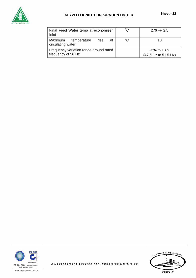
Final Feed Water temp at economizer Inlet
0C 276 +/- 2.5
Maximum temperature rise of circulating water
0C 10
Frequency variation range around rated frequency of 50 Hz
-5% to +3% (47.5 Hz to 51.5 Hz)
NEYVELI LIGNITE CORPORATION LIMITED
Sheet - 23
ISO 9001:2008 Registered Company Certificate No. 10692
CIN : U74899DL1970PTC005474
A D e v e l o p m e n t S e r v i c e f o r I n d u s t r i e s & U t i l i t i e s
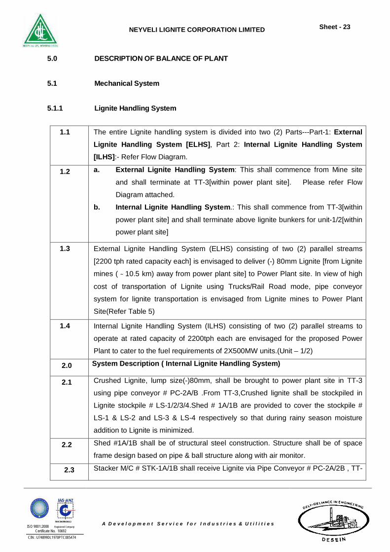
5.0 DESCRIPTION OF BALANCE OF PLANT
5.1 Mechanical System
5.1.1 Lignite Handling System
1.1 The entire Lignite handling system is divided into two (2) Parts---Part-1: External
Lignite Handling System [ELHS], Part 2: Internal Lignite Handling System [ILHS]:- Refer Flow Diagram.
1.2 a. External Lignite Handling System: This shall commence from Mine site
and shall terminate at TT-3[within power plant site]. Please refer Flow
Diagram attached.
b. Internal Lignite Handling System.: This shall commence from TT-3[within
power plant site] and shall terminate above lignite bunkers for unit-1/2[within
power plant site]
1.3 External Lignite Handling System (ELHS) consisting of two (2) parallel streams
[2200 tph rated capacity each] is envisaged to deliver (-) 80mm Lignite [from Lignite
mines ( ̴ 10.5 km) away from power plant site] to Power Plant site. In view of high
cost of transportation of Lignite using Trucks/Rail Road mode, pipe conveyor
system for lignite transportation is envisaged from Lignite mines to Power Plant
Site(Refer Table 5)
1.4 Internal Lignite Handling System (ILHS) consisting of two (2) parallel streams to
operate at rated capacity of 2200tph each are envisaged for the proposed Power
Plant to cater to the fuel requirements of 2X500MW units.(Unit – 1/2)
2.0 System Description ( Internal Lignite Handling System)
2.1 Crushed Lignite, lump size(-)80mm, shall be brought to power plant site in TT-3
using pipe conveyor # PC-2A/B .From TT-3,Crushed lignite shall be stockpiled in
Lignite stockpile # LS-1/2/3/4.Shed # 1A/1B are provided to cover the stockpile #
LS-1 & LS-2 and LS-3 & LS-4 respectively so that during rainy season moisture
addition to Lignite is minimized.
2.2 Shed #1A/1B shall be of structural steel construction. Structure shall be of space
frame design based on pipe & ball structure along with air monitor.
2.3 Stacker M/C # STK-1A/1B shall receive Lignite via Pipe Conveyor # PC-2A/2B , TT-
NEYVELI LIGNITE CORPORATION LIMITED
Sheet - 24
ISO 9001:2008 Registered Company Certificate No. 10692
CIN : U74899DL1970PTC005474
A D e v e l o p m e n t S e r v i c e f o r I n d u s t r i e s & U t i l i t i e s
3 ,JT-1 and yard belt conv. # YBC-1A/1B.Above Stacker M/C shall stack crushed
Lignite in Stockpile # LS-1/2/3/4.Stacker M/C have also stockpile bypass facility so
that Lignite can be fed directly to Lignite Bunkers using connected conveyor system
including bunker feeding Conv. # BC-3A/3B.
2.4 Bunker feeding Conveyors # BC-3A/3B are provided with fixed V-plough feeder that
discharge Lignite into the Lignite bunkers.
2.5 In case, Lignite is not received from Mine Site i.e. if ELHS is not functioning, then
Lignite from Stockpile# LS-1/2/3/4 shall be reclaimed by Reclaimer M/C # RCL-
1A/1B & fed onto yard Conv. # YBC-1A/1B which in turn shall feed Lignite Bunkers
using connected conveyor system & bunker feeding conveyor # BC- 3A/3B.
3.0 System Description ( External Lignite Handling System)
3.1 Four (4) Feeder Breaker # FB-1A/2A/1B/2B for crushing Lignite have been
incorporated in ELHS so that Lignite (as mined) is fed into the Feed Hopper of Feed
Breaker. Each feeder breaker shall operate at rated capacity of 1100tph.Feeder
breaker input shall be 800-1200mm Lignite.
3.2 Each feeder consists of a feed hopper beneath which crusher & chain conveyor are
mounted whereby Lignite is crushed & conveyed onto belt conveyor # BCN-
1A/1B.Feeder breaker output shall be
(-) 200mm lignite that is fed onto Conv.# BCN-1A/1B by chain conveyor integrated
with Feeder Breaker.
3.3 Conv.# BCN-1A/1B shall transport lignite to crusher house# CRH-1 & feed it into
Roller Screen#RS-1A/1B, that remove (-) 80mm Lignite from its feed & the
remaining oversize material is fed into Crushers # CR-1A/1B. Crushers # CR-1A/1B
shall crush lignite to (-) 80mm product & deliver it onto Belt Feeder # BFN-1A/1B.
Undersize material from bottom of Screen# RS-1A/1B is also fed directly via chute
onto Belt Feeder # BFN-1A/1B.
3.4 Belt Feeder # BFN-1A/1B shall feed crushed lignite to Sacrificial Conveyor # SFC-
1A/1B which in turn feed lignite to pipe conv. # PC-1A/1B. Pipe conv. # PC-1A/1B
shall feed material into another pair of pipe belt conveyor # PC-2A/2B for onward
transport of lignite to TT-3 located at power plant site.
3.5 To ensure trouble free flow of lignite from one equipment to the succeeding
equipment, one to one equipment feeding i.e single way chute are incorporated in
ELHS as well as in ILHS.
NEYVELI LIGNITE CORPORATION LIMITED
Sheet - 25
ISO 9001:2008 Registered Company Certificate No. 10692
CIN : U74899DL1970PTC005474
A D e v e l o p m e n t S e r v i c e f o r I n d u s t r i e s & U t i l i t i e s
3.6 Sacrificial Conveyor # SFC-1A/1B have been incorporated so that metal free lignite
is fed into Pipe belt conv.# PC-1A/1B .Hence Suspended Magnet (SEMN), Metal
Detector (MDN)& In-line Magnetic Separator (ILMSN) are installed on above Conv.
# SFC-1A/1B
3.7 Two(2) pair of pipe belt[i.e. PC-1A/B & PC-2A/2B]are incorporated so that pipe belt
direction towards Power Plant from Mines can be achieved at site with ease
whereby overcoming any hurdles/constraints on ground level or due to
waterbody,acquisition of corridor etc.
4.0 Important Technical Features (ILHS/ELHS):
4.1 Both Lignite Handling Systems shall be designed so that both streams can be
operated simultaneously. Adequate facilities are provided for crushing/ storage/
reclaim and conveyance of crushed Lignite to Lignite Bunkers in above ILHS/ELHS.
4.2 Two (2) Slewing cum luffing type, rail mounted Stacker M/C along with Two (2)
Slewing cum luffing type, rail mounted - Bucket wheel type Reclaimer M/C are
proposed for storage/ reclaim & for subsequent transport of crushed Lignite to
Bunkers of Unit-1/2 from stockpiles.
4.3 All Junction Towers & Crusher House shall be in steel frame construction with RCC
floors & RCC roof. Side cladding shall be of precolor coated sheeting.
4.4 ILHS/ELHS shall also include all other necessary & required equipments / Aux
systems/ items etc. as noted below for their satisfactory operation.
a. Shuttle Conveyor at discharge end of appropriate conveyors shall be provided for
stream selection [changing] for flexibility of operation.
b. Suitable sampling system shall be provided for Lignite.
c. Two (2) no. Elevator shall be provided, one (1) in Crusher House # CRH-1 & other
for Junction Tower near Bunkers.
d. Vibration Isolation System shall also be provided for Conv. drives located at floors
having elevations of 15m and above 15m.
e. For Buildings (under ILHS/ELHS) viz. Junction Towers / Crusher House etc. -----
Manual Hoists/ Electric Operated Hoist are envisaged for handling cum maintenance
purpose for equipments.
f. Anti-collision device shall be provided for bulk handling M/C viz. Stacker M/C &
Reclaimer M/C.3-D scanner for stockpile capacity determination shall be provided
below boom belt of above machine
g. For Main Control Room, Split type window A.C. unit shall be provided in addition to
NEYVELI LIGNITE CORPORATION LIMITED
Sheet - 26
ISO 9001:2008 Registered Company Certificate No. 10692
CIN : U74899DL1970PTC005474
A D e v e l o p m e n t S e r v i c e f o r I n d u s t r i e s & U t i l i t i e s
wall-mounted swiveling fans. Exhaust fans for Battery Room, Split type A.C. unit for
Electric House of Stacker M/C & Reclaimer M/C are envisaged. Unitary type
Pressure Ventilation System is proposed for each MCC Room for above Lignite
handling system.
4.5 Four (4) dozers and Four (4) front end loaders shall be provided for stockpile
compaction /piling etc and also for housekeeping of Lignite Handling System.
4.6 DCS system shall be provided for operation & control of ILHS/ELHS. Similarly each
Stacker M/C & Reclaimer M/C shall be provided with DCS system for its operation &
control for working suitably in conjunction with its yard belt.
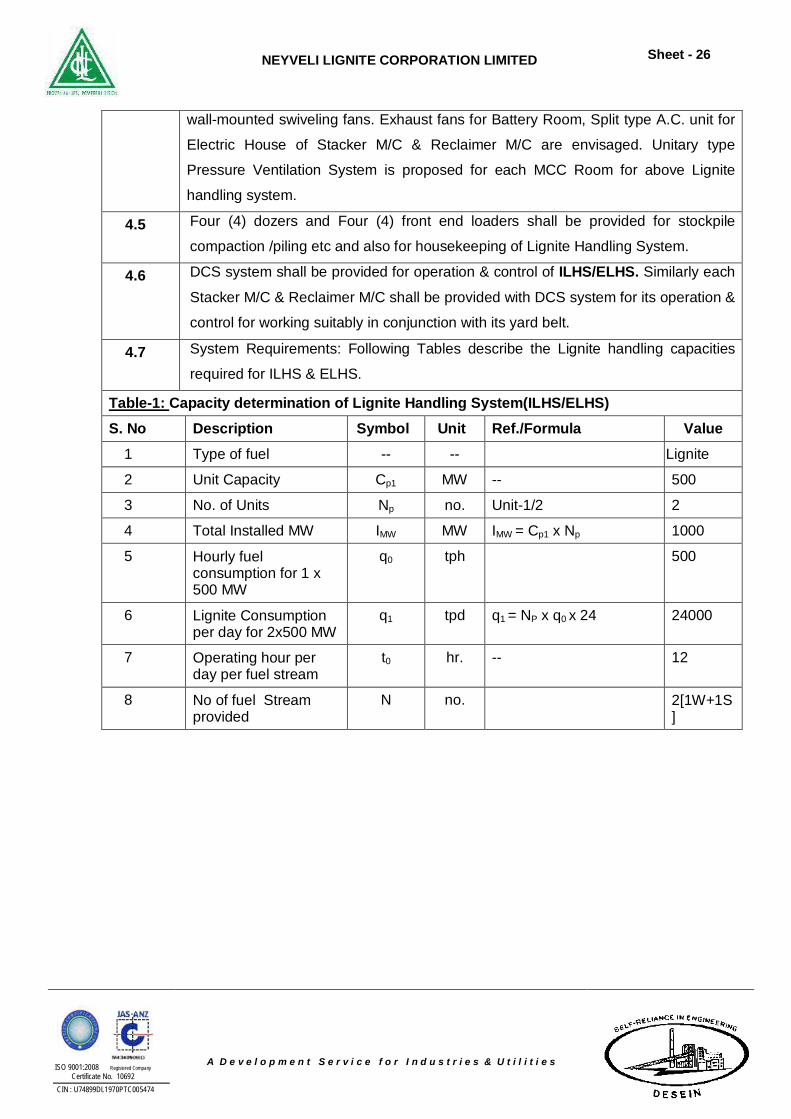
4.7 System Requirements: Following Tables describe the Lignite handling capacities
required for ILHS & ELHS.
Table-1: Capacity determination of Lignite Handling System(ILHS/ELHS) S. No Description Symbol Unit Ref./Formula Value
1 Type of fuel -- -- Lignite
2 Unit Capacity Cp1 MW -- 500
3 No. of Units Np no. Unit-1/2 2
4 Total Installed MW IMW MW IMW = Cp1 x Np 1000
5 Hourly fuel consumption for 1 x 500 MW
q0 tph 500
6 Lignite Consumption per day for 2x500 MW
q1 tpd q1 = NP x q0 x 24 24000
7 Operating hour per day per fuel stream
t0 hr. -- 12
8 No of fuel Stream provided
N no. 2[1W+1S]
NEYVELI LIGNITE CORPORATION LIMITED
Sheet - 27
ISO 9001:2008 Registered Company Certificate No. 10692
CIN : U74899DL1970PTC005474
A D e v e l o p m e n t S e r v i c e f o r I n d u s t r i e s & U t i l i t i e s
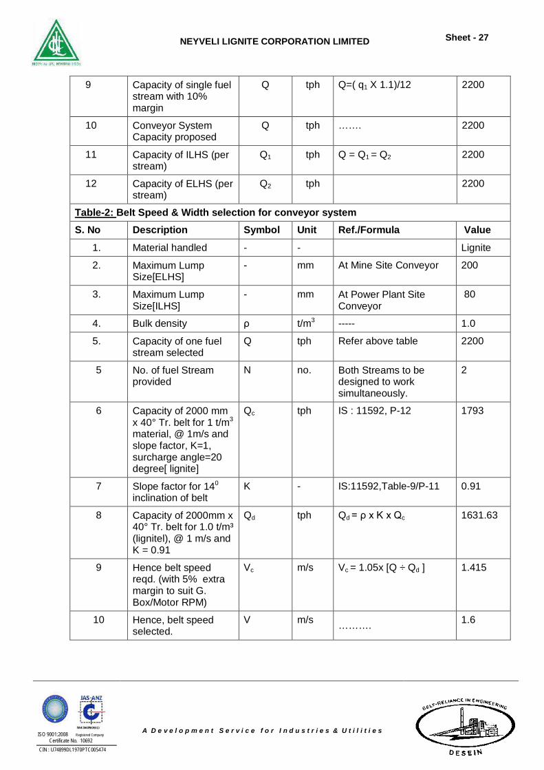
9 Capacity of single fuel stream with 10% margin
Q tph Q=( q1 X 1.1)/12 2200
10 Conveyor System Capacity proposed
Q tph ……. 2200
11 Capacity of ILHS (per stream)
Q1 tph Q = Q1 = Q2 2200
12 Capacity of ELHS (per stream)
Q2 tph 2200
Table-2: Belt Speed & Width selection for conveyor system S. No Description Symbol Unit Ref./Formula Value
1. Material handled - - Lignite
2. Maximum Lump Size[ELHS]
- mm At Mine Site Conveyor 200
3. Maximum Lump Size[ILHS]
- mm At Power Plant Site Conveyor
80
4. Bulk density ρ t/m3 ----- 1.0
5. Capacity of one fuel stream selected
Q tph Refer above table 2200
5 No. of fuel Stream provided
N no. Both Streams to be designed to work simultaneously.
2
6 Capacity of 2000 mm x 40° Tr. belt for 1 t/m3 material, @ 1m/s and slope factor, K=1, surcharge angle=20 degree[ lignite]
Qc tph IS : 11592, P-12 1793
7 Slope factor for 140 inclination of belt
K - IS:11592,Table-9/P-11 0.91
8 Capacity of 2000mm x 40° Tr. belt for 1.0 t/m³ (lignitel), @ 1 m/s and K = 0.91
Qd tph Qd = ρ x K x Qc 1631.63
9 Hence belt speed reqd. (with 5% extra margin to suit G. Box/Motor RPM)
Vc m/s Vc = 1.05x [Q ÷ Qd ] 1.415
10 Hence, belt speed selected.
V m/s ………. 1.6
NEYVELI LIGNITE CORPORATION LIMITED
Sheet - 28
ISO 9001:2008 Registered Company Certificate No. 10692
CIN : U74899DL1970PTC005474
A D e v e l o p m e n t S e r v i c e f o r I n d u s t r i e s & U t i l i t i e s
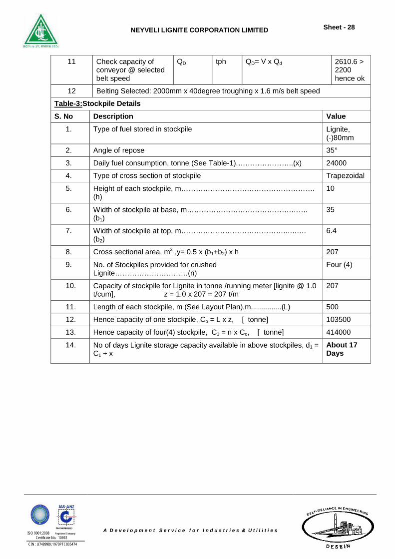
11 Check capacity of conveyor @ selected belt speed
QD tph QD= V x Qd 2610.6 > 2200 hence ok
12 Belting Selected: 2000mm x 40degree troughing x 1.6 m/s belt speed
Table-3:Stockpile Details S. No Description Value
1. Type of fuel stored in stockpile Lignite, (-)80mm
2. Angle of repose 35°
3. Daily fuel consumption, tonne (See Table-1).…………………..(x) 24000
4. Type of cross section of stockpile Trapezoidal
5. Height of each stockpile, m………………………………………………. (h)
10
6. Width of stockpile at base, m…………………………………….……. (b1)
35
7. Width of stockpile at top, m……………………………………..….…. (b2)
6.4
8. Cross sectional area, m2 ,y= 0.5 x (b1+b2) x h 207
9. No. of Stockpiles provided for crushed Lignite…………………………(n)
Four (4)
10. Capacity of stockpile for Lignite in tonne /running meter [lignite @ 1.0 t/cum], z = 1.0 x 207 = 207 t/m
207
11. Length of each stockpile, m (See Layout Plan),m...............(L) 500
12. Hence capacity of one stockpile, Co = L x z, [ tonne] 103500
13. Hence capacity of four(4) stockpile, C1 = n x Co, [ tonne] 414000
14. No of days Lignite storage capacity available in above stockpiles, d1 = C1 ÷ x
About 17 Days
NEYVELI LIGNITE CORPORATION LIMITED
Sheet - 29
ISO 9001:2008 Registered Company Certificate No. 10692
CIN : U74899DL1970PTC005474
A D e v e l o p m e n t S e r v i c e f o r I n d u s t r i e s & U t i l i t i e s
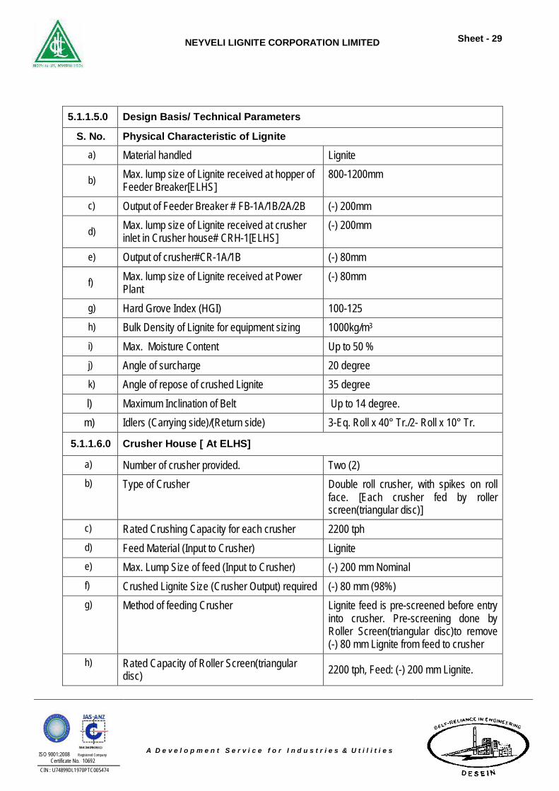
5.1.1.5.0 Design Basis/ Technical Parameters
S. No. Physical Characteristic of Lignite
a) Material handled Lignite
b) Max. lump size of Lignite received at hopper of Feeder Breaker[ELHS]
800-1200mm
c) Output of Feeder Breaker # FB-1A/1B/2A/2B (-) 200mm
d) Max. lump size of Lignite received at crusher inlet in Crusher house# CRH-1[ELHS]
(-) 200mm
e) Output of crusher#CR-1A/1B (-) 80mm
f) Max. lump size of Lignite received at Power Plant
(-) 80mm
g) Hard Grove Index (HGI) 100-125 h) Bulk Density of Lignite for equipment sizing 1000kg/m3 i) Max. Moisture Content Up to 50 % j) Angle of surcharge 20 degree k) Angle of repose of crushed Lignite 35 degree l) Maximum Inclination of Belt Up to 14 degree.
m) Idlers (Carrying side)/(Return side) 3-Eq. Roll x 40° Tr./2- Roll x 10° Tr.
5.1.1.6.0 Crusher House [ At ELHS]
a) Number of crusher provided. Two (2) b) Type of Crusher Double roll crusher, with spikes on roll
face. [Each crusher fed by roller screen(triangular disc)]
c) Rated Crushing Capacity for each crusher 2200 tph d) Feed Material (Input to Crusher) Lignite e) Max. Lump Size of feed (Input to Crusher) (-) 200 mm Nominal f) Crushed Lignite Size (Crusher Output) required (-) 80 mm (98%) g) Method of feeding Crusher Lignite feed is pre-screened before entry
into crusher. Pre-screening done by Roller Screen(triangular disc)to remove (-) 80 mm Lignite from feed to crusher
h) Rated Capacity of Roller Screen(triangular disc) 2200 tph, Feed: (-) 200 mm Lignite.
NEYVELI LIGNITE CORPORATION LIMITED
Sheet - 30
ISO 9001:2008 Registered Company Certificate No. 10692
CIN : U74899DL1970PTC005474
A D e v e l o p m e n t S e r v i c e f o r I n d u s t r i e s & U t i l i t i e s
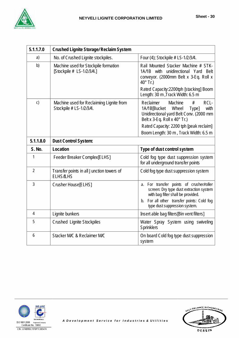
5.1.1.7.0 Crushed Lignite Storage/ Reclaim System a) No. of Crushed Lignite stockpiles. Four (4); Stockpile # LS-1/2/3/4. b) Machine used for Stockpile formation
[Stockpile # LS-1/2/3/4.] Rail Mounted Stacker Machine # STK-1A/1B with unidirectional Yard Belt conveyor. (2000mm Belt x 3-Eq. Roll x 40° Tr.) Rated Capacity:2200tph [stacking] Boom Length: 30 m ,Track Width: 6.5 m
c) Machine used for Reclaiming Lignite from Stockpile # LS-1/2/3/4.
Reclaimer Machine # RCL-1A/1B[Bucket Wheel Type] with Unidirectional yard Belt Conv. (2000 mm Belt x 3-Eq. Roll x 40° Tr.) Rated Capacity: 2200 tph [peak reclaim] Boom Length: 30 m , Track Width: 6.5 m
5.1.1.8.0 Dust Control System: S. No. Location Type of dust control system
1 Feeder Breaker Complex[ELHS] Cold fog type dust suppression system for all underground transfer points
2 Transfer points in all Junction towers of ELHS/ILHS
Cold fog type dust suppression system
3 Crusher House[ELHS] a. For transfer points of crusher/roller screen: Dry type dust extraction system with bag filter shall be provided.
b. For all other transfer points: Cold fog type dust suppression system.
4 Lignite bunkers Insert able bag filters[Bin vent filters] 5 Crushed Lignite Stockpiles Water Spray System using swiveling
Sprinklers 6 Stacker M/C & Reclaimer M/C On board Cold fog type dust suppression
system
NEYVELI LIGNITE CORPORATION LIMITED
Sheet - 31
ISO 9001:2008 Registered Company Certificate No. 10692
CIN : U74899DL1970PTC005474
A D e v e l o p m e n t S e r v i c e f o r I n d u s t r i e s & U t i l i t i e s
Table: 5 Comparison Of Various Modes Of Transport For Conveying Lignite
From Lignite Mines To Power Plant Site Approx. Distance : 10.5 Km Between Mine & Power Plant
S. No. Mode of Transport
Technical Aspects Economic Aspect Remarks
1. Railway Transportation
Due to moisture in lignite, the lignite wagons cannot be fully emptied by wagon unloading equipment viz. wagon tippler, track hopper / bottom discharge wagon etc.
Wagon unloading system will frequently choke. hence not recommended
High Capital Investment due to : Construction of Railway Tracks,
culverts, bridges, drains etc. Construction of Railway siding,
procurement of Locos, loco shed etc. at Power plant site.
At mine site high loading rates into rail wagons cannot be achieved due to moisture in lignite. As a result additional rakes would be required.
Not recommended
2. Truck Transportation
Inefficient unloading operation of Lignite from Trucks/ Tippler / Truck tippler/ Reclaim Hopper etc. at power plant site due to moisture in lignite
At mine site high loading rates into trucks cannot be achieved due to moisture in lignite. As a result additional trucks/tipper would be required.
Environmental issues due to spillage of lignite on route and operation of diesel operated trucks.
High Capital Investment due to : Construction of roads, culverts,
bridges, drains etc. Construction of truck parking sheds
at Power plant site. Large fleet of trucks required Maintenance costs for trucks/ road
along route.
Not recommended
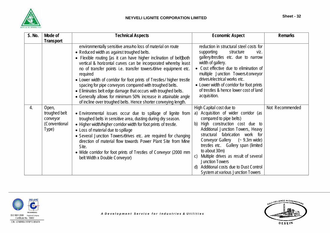
3. Pipe Conveyor System
High mass flow rates/enclosed conveying system suitable for long distance conveying/dust free installation/very good for
Higher pipe belt costs as compared to troughed belts but substantial
Recommended & proposed
NEYVELI LIGNITE CORPORATION LIMITED
Sheet - 32
ISO 9001:2008 Registered Company Certificate No. 10692
CIN : U74899DL1970PTC005474
A D e v e l o p m e n t S e r v i c e f o r I n d u s t r i e s & U t i l i t i e s
S. No. Mode of Transport
Technical Aspects Economic Aspect Remarks
environmentally sensitive area/no loss of material on route Reduced width as against troughed belts. Flexible routing [as it can have higher inclination of belt]both
vertical & horizontal curves can be incorporated whereby least no of transfer points i.e. transfer towers/drive equipment etc. required
Lower width of corridor for foot prints of Trestles/ higher trestle spacing for pipe conveyors compared with troughed belts.
Eliminates belt edge damage that occurs with troughed belts. Generally allows for minimum 50% increase in attainable angle
of incline over troughed belts. Hence shorter conveying length.
reduction in structural steel costs for supporting structure viz. gallery/trestles etc. due to narrow width of gallery.
Cost effective due to elimination of multiple Junction Towers/conveyor drives/electrical works etc.
Lower width of corridor for foot prints of trestles & hence lower cost of land acquisition.
4. Open, troughed belt conveyor (Conventional Type)
Environmental issues occur due to spillage of lignite from
troughed belts in sensitive area, dusting during dry season. Higher width/higher corridor width for foot prints of trestle. Loss of material due to spillage Several Junction Towers/drives etc. are required for changing
direction of material flow towards Power Plant Site from Mine Site.
Wide corridor for foot prints of Trestles of Conveyor (2000 mm belt Width x Double Conveyor)
High Capital cost due to a) Acquisition of wider corridor (as
compared to pipe belts) b) High construction cost due to
Additional Junction Towers, Heavy structural fabrication work for Conveyor Gallery (~ 9.3m wide) trestles etc. Gallery span (limited to about 30m)
c) Multiple drives as result of several Junction Towers
d) Additional costs due to Dust Control System at various Junction Towers
Not Recommended
NEYVELI LIGNITE CORPORATION LIMITED
Sheet - 33
ISO 9001:2008 Registered Company Certificate No. 10692
CIN : U74899DL1970PTC005474
A D e v e l o p m e n t S e r v i c e f o r I n d u s t r i e s & U t i l i t i e s
5.1.2 Ash Handling Plant
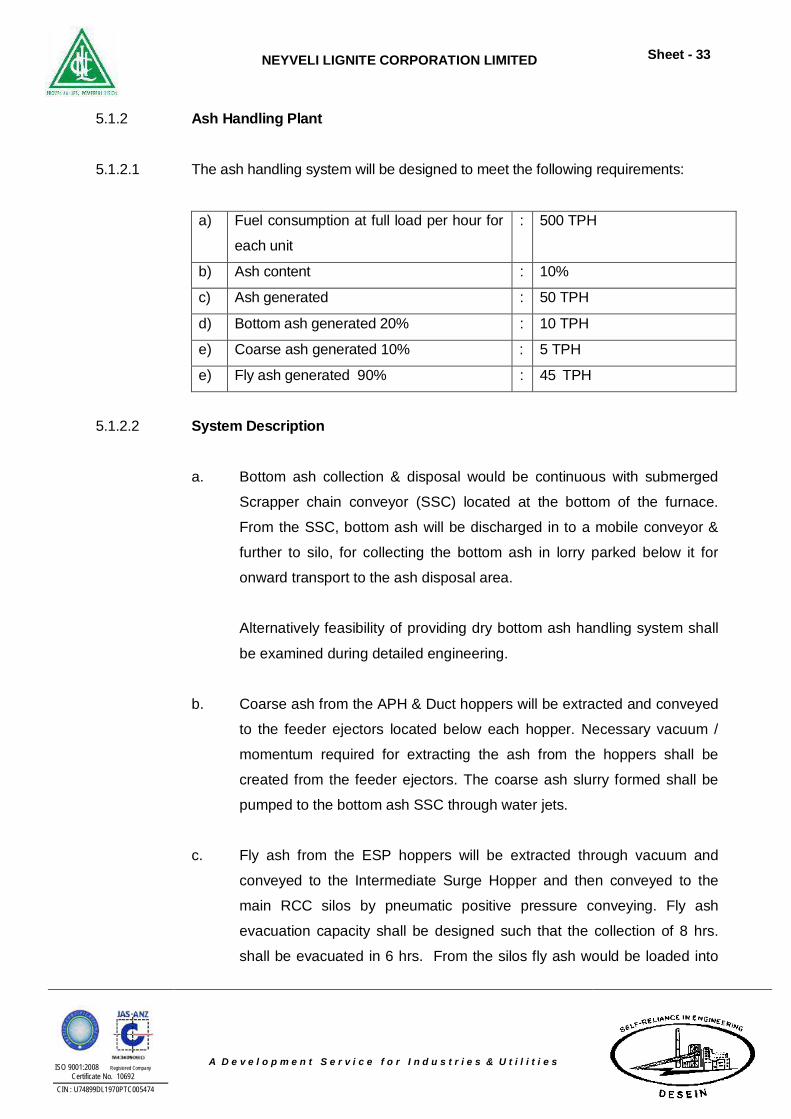
5.1.2.1 The ash handling system will be designed to meet the following requirements:
a) Fuel consumption at full load per hour for
each unit : 500 TPH
b) Ash content : 10% c) Ash generated : 50 TPH d) Bottom ash generated 20% : 10 TPH e) Coarse ash generated 10% : 5 TPH e) Fly ash generated 90% : 45 TPH
5.1.2.2 System Description
a. Bottom ash collection & disposal would be continuous with submerged
Scrapper chain conveyor (SSC) located at the bottom of the furnace.
From the SSC, bottom ash will be discharged in to a mobile conveyor &
further to silo, for collecting the bottom ash in lorry parked below it for
onward transport to the ash disposal area.
Alternatively feasibility of providing dry bottom ash handling system shall
be examined during detailed engineering.
b. Coarse ash from the APH & Duct hoppers will be extracted and conveyed
to the feeder ejectors located below each hopper. Necessary vacuum /
momentum required for extracting the ash from the hoppers shall be
created from the feeder ejectors. The coarse ash slurry formed shall be
pumped to the bottom ash SSC through water jets.
c. Fly ash from the ESP hoppers will be extracted through vacuum and
conveyed to the Intermediate Surge Hopper and then conveyed to the
main RCC silos by pneumatic positive pressure conveying. Fly ash
evacuation capacity shall be designed such that the collection of 8 hrs.
shall be evacuated in 6 hrs. From the silos fly ash would be loaded into
NEYVELI LIGNITE CORPORATION LIMITED
Sheet - 34
ISO 9001:2008 Registered Company Certificate No. 10692
CIN : U74899DL1970PTC005474
A D e v e l o p m e n t S e r v i c e f o r I n d u s t r i e s & U t i l i t i e s
trucks to facilitate dispatch of fly ash to consumers. In case of exigencies,
fly ash can be disposed off to ash dyke as lean slurry from silos. The fly
ash storage silos would be designed to have a storage capacity of
minimum twenty four hours fly ash generated.
5.1.2.3 Bottom Ash Handling System
The ash from after burning grate (ABG) falls through ABG discharge hopper in to
submerged scrapper chain conveyor (SCC). The submerged scrapper chain
conveyor (SCC) continuously conveys the bottom ash into a mobile belt conveyor
& further to silo, which would convey the wet ash to the lorry parked below it. The
capacity of the bottom ash mobile belt conveyor can be selected to suit the
bottom ash generation. The bottom ash loaded in the trucks shall be transported
to the ash disposal area.
5.1.2.4 Coarse Ash Handling System
a. Coarse ash from the APH & Duct hoppers will be extracted and conveyed
to the feeder ejectors located below each hopper. Necessary vacuum /
momentum required for extracting the ash from the hoppers shall be
created from the feeder ejectors. The coarse ash slurry formed shall be
pumped to the bottom ash SSC through water jets.
b. The water required for feeder ejectors will be drawn from HP water
pumps.
5.1.2.5 Fly Ash Handling System
a. Fly ash from the ESP hoppers will be extracted through vacuum and
conveyed to the Intermediate Surge Hoppers (ISH) and then conveyed to
the main RCC silos by pneumatic positive pressure conveying. Fly ash
evacuation capacity shall be designed such that the collection of 8 hrs.
shall be evacuated in 6 hrs. From the silos fly ash would be loaded into
trucks to facilitate dispatch of fly ash to consumers. In case of
exigencies, fly ash can be disposed off to ash dyke as lean slurry from
NEYVELI LIGNITE CORPORATION LIMITED
Sheet - 35
ISO 9001:2008 Registered Company Certificate No. 10692
CIN : U74899DL1970PTC005474
A D e v e l o p m e n t S e r v i c e f o r I n d u s t r i e s & U t i l i t i e s
silos. The fly ash storage silos would be designed to have a storage
capacity of forty eight hours of fly ash generated.
b. Four (4) ISH shall be provided per unit for collecting the fly ash from each
ESP pass. Two (1W+1S) dry fly ash conveying lines shall be envisaged
from each ISH to convey the fly ash collected to the Main RCC silos by
pneumatic positive pressure conveying system. Hence, total 8 conveying
lines (4W+4S) shall be provided for each unit.
5.1.2.6 Disposal of Fly Ash from Main RCC Silo
Four nos. of RCC silos would be envisaged to have a storage capacity of 1000
tonnes each, which caters for 48 hrs. storage capacity of ash generated in both
the units. Two dedicated interconnected silos shall be provided for each unit. The
dry fly ash collected in the storage silo would be normally disposed in the dry
form. Five outlets would be provided for each silo, out of which two for closed
Truck loading, one for open tanker loading, fourth opening for lean slurry disposal
system use and fifth opening for future along with blind flange. The fly ash would
be unloaded into closed trucks in dry form through rotary feeder & dry unloading
chute. In case of open trucks fly ash would be unloaded in conditioned form by
rotary feeder & double shaft paddle type dust conditioners or rotary ash
conditioner and dispatched to consumers/disposal area. The fly ash conveying
air would be vented to the atmosphere from the silo through vent bag filter to
mitigate the environmental pollution.
5.1.2.7 Ash Slurry Disposal System
As an emergency fall back arrangement, lean slurry disposal system is also
envisaged from the out let of the fly ash silo.
Fly ash slurry from the silos will be discharged into the Ash Slurry Sump. From
ash slurry sump slurry shall be disposed to the ash disposal area by means of
ash disposal pumps and associated piping. It is envisaged to provide a single
series consists of four ash disposal pumps for the slurry transportation system.
The discharge head of the slurry pumps will be designed considering slurry
NEYVELI LIGNITE CORPORATION LIMITED
Sheet - 36
ISO 9001:2008 Registered Company Certificate No. 10692
CIN : U74899DL1970PTC005474
A D e v e l o p m e n t S e r v i c e f o r I n d u s t r i e s & U t i l i t i e s
formation from the both the units with one pipe line & associated utilities. Each
time at the end of disposal of ash slurry in a shift, the complete disposal line shall
be flushed with water for few minutes to prevent settling of ash in the ash slurry
pipe line.
5.1.2.8 Ash Dyke
Fly ash from each unit would be disposed off in slurry from in the proposed ash
dyke in case of any exigency.
5.1.2.9 Ash Water Recovery System
Ash water recovery system shall be provided to recover water from the ash dyke.
The details of anticipated recovery will be provided during detailed engineering.
The conservative estimate of recovery will be around 70% and is applicable in
case of wet ash handling system.
5.1.2.10 Major Equipment
5.1.2.10.1 Bottom Ash Handling System
Mobile Belt Conveyor
Mobile Bottom ash belt conveyor would be used to convey the bottom ash from
the Scraper Chain Conveyor (SSC) to the truck. The capacity of the belt
conveyors will be based on the bottom ash and coarse ash generation per boiler.
5.1.2.10.2 Fly Ash Handling System
Fly ash removal system would be designed to collect fly ash from ESP hoppers
using pneumatic vacuum conveying up to ISH and positive pneumatic conveying
from the ISH to silos.
NEYVELI LIGNITE CORPORATION LIMITED
Sheet - 37
ISO 9001:2008 Registered Company Certificate No. 10692
CIN : U74899DL1970PTC005474
A D e v e l o p m e n t S e r v i c e f o r I n d u s t r i e s & U t i l i t i e s
5.1.2.10.3 Vacuum Pumps
Eight (8) (4W+4S) number of liquid ring type vacuum pumps would be provided
for each unit to create necessary vacuum to convey dry fly ash up to ISH.
5.1.2.10.4 Conveying Air Compressors - Oil Free Screw Type
The requirement of compressed air for conveying ash from the ISH to the storage
silo would be met by six (6) oil free rotary screw compressors (4W+2S) common
for both units. Adequately sized of air receivers shall be envisaged for both the
units. Air compressors with refrigerant air dryers of suitable capacity would be
provided.
5.1.2.10.5 Instrument Air Compressors - Oil Free Screw Compressors
The requirement of compressed air for instruments, operation of pneumatic
valves in the system, bag filter cleaning air etc., would be met by Instrument air
compressors. Four (4) compressors (2W+2S) with associated driers (HOC type)
and air receivers would be provided for both unit. One 2m3/hr instrument air
receiver shall also be provided at the silo area for silo instruments.
5.1.2.10.6 ESP hoppers, Intermediate Surge Hoppers & Silo Fluidizing Blowers
Four adequately sized fluidizing air blowers with heaters shall be provided for
each unit to meet the fluidizing air requirement of fly ash hopper and ISH
(intermediate surge hoppers). Out of four, two will be working and the other two
will be standby. Similarly, silo aeration is met by eight (8) nos. of blowers and
heater out of which four blowers will be working and the other four will be stand
by.
5.1.2.10.7 Fly Ash Piping and Valves
Cast iron pipes will be used for extracting ash from the ESP hoppers to the ISH.
ASTM A106 Gr ‘B” CS seamless pipe of schedule 80 will be provided for positive
NEYVELI LIGNITE CORPORATION LIMITED
Sheet - 38
ISO 9001:2008 Registered Company Certificate No. 10692
CIN : U74899DL1970PTC005474
A D e v e l o p m e n t S e r v i c e f o r I n d u s t r i e s & U t i l i t i e s
pneumatic conveying of ash from ISH to silos. The ash hopper isolation valves
would be of knife gate type, made of stainless steel (ANSI 410) gate hard faced
by nitriding to get a minimum hardness of 450 BHN while the seat and body
would be made of alloy C.I. with 2.5% Ni, minimum hardness 340 BHN. Ceramic
lined bends and fittings shall be used for fly ash conveying system from ISH to
silo and for vacuum conveying ACI bends of minimum 500 BHN shall be used.
5.1.2.10.8 High Pressure Water Pumps
The HP water pumps would be horizontal, centrifugal type, and would supply
water at required quantity and pressure for Jet pump, slurry sump flushing, ash
slurry disposal line flushing. Three (3) HP water pumps would be provided, out of
which one would be operating for each unit to meet the total HP water
requirement of the system while the other one would serve as a common
standby.
5.1.2.10.9 LP Water Pumps
Three numbers (2W+1S) of Ash water pumps would be provided for the slurry
disposal system. These pumps would operate to meet the water requirement of
wet disposal system for Fly ash. Ash water pumps would take suction from the
ash water tank.
5.1.2.10.10 Ash Slurry Pump House
Four pumps connected in series shall be provided for the slurry disposal system.
The ash slurry pumps would be provided with V-belt drives with vary-pitch
sheaves to vary the pump speed in future, as required, depending upon the
disposal distance and/or wear of the impeller. All the pumps would be connected
to one ash slurry disposal line.
5.1.2.11 Major Structures
5.1.2.11.1 Ash Water and Ash Slurry Pump House including Silo Utility Building
Ash water pump house would be provided with HP & LP water pumps, Slurry
pumps, seal water pump etc. Ash slurry sump would have an optimum capacity
NEYVELI LIGNITE CORPORATION LIMITED
Sheet - 39
ISO 9001:2008 Registered Company Certificate No. 10692
CIN : U74899DL1970PTC005474
A D e v e l o p m e n t S e r v i c e f o r I n d u s t r i e s & U t i l i t i e s
to hold the ash slurry formed (bottom ash and fly ash) in about five minutes of
ash generated of both units. The sump would be provided with suitable alloy cast
iron liners, agitating nozzles, overflow connections, etc. The pump house would
be provided adjoining the sump. The pump house would be complete with
pendant operated under slung crane, drainage facilities, sump pumps, etc.
A separate bay shall be provided in the ash slurry pump house for
accommodating the silo fluidising blowers and its electrics. The location of the
ash slurry pump house shall be as nearer as silos.
5.1.2.11.2 Compressor House
Compressor house would be housing oil free screw conveying air compressors,
instrument air compressors, fluidizing blowers for ISH and fly ash hoppers
fluidization, vacuum pumps and sealing water pumps. The compressor house
would be complete with under slung crane, drainage facilities, etc. Separate
compressor house shall be provided each unit.
5.1.2.11.3 Ash Disposal Area
The ash disposal area would be provided with protective layer as lining in order
to prevent any seepage. Fly ash would be disposed off to the proposed dyke in
lean slurry disposal system.
5.1.2.11.4 Ash Water Recovery Pump House
Ash water recovery pump house would be housing recovery water pumps. The
pump house would be complete with under slung crane, drainage facilities, sump
pumps, etc. Ash water recovery pump houses will be located near Ash pond
area. Two numbers of Ash water recovery pump would be provided.
NEYVELI LIGNITE CORPORATION LIMITED
Sheet - 40
ISO 9001:2008 Registered Company Certificate No. 10692
CIN : U74899DL1970PTC005474
A D e v e l o p m e n t S e r v i c e f o r I n d u s t r i e s & U t i l i t i e s
5.1.3 Plant Water System
The major components of the Plant Water System for both units are as follows:
1. Raw Water Reservoir
2. Raw Water Pumps with drives and accessories on Raw Water Reservoir.
3. Pretreatment Plant
4. Clarified Water Reservoir including storage for fire water.
5. CT Makeup, Service water, Jockey & fire hydrant and DM Plant Supply
Pumps with drives and accessories on Clarified Water Reservoir.
6. Demineralizing Plant
7. Hot Well Makeup Pumps with drives and accessories.
8. Raw Water & CW Chlorination System.
5.1.3.1 Raw Water Source
The source of raw water for the proposed second expansion project of 2X500
MW NLC shall be the ground water from the proposed lignite mines III & storm
water. Raw water requirement is worked out to be 2588 M3/ Hr as per the
attached composite. Sufficient raw water is available as per the detailed below:
GWC pumping - 1135 M3/ Hr (5000 GPM)
Seepage well pumping – 454 M3/ Hr (2000 GPM)
Storm water pumping – 1816 M3/ Hr (8000 GPM)
Total - 3405 M3/ Hr (15000 GPM)
The entire raw water requirement for the proposed project shall be pumped from
the proposed lignite mines III and stored in plant Lake. The capacity of this lake
shall be equivalent to the 7 days of consumptive requirement.
Three (3) Nos. (2W+1S) Raw Water intake Pumps each of capacity 1600 M3/hr
with adequate head shall be provided. These pumps shall be vertical, turbine
type with associated drives and accessories shall be provided, with stop log
gates and screens.
NEYVELI LIGNITE CORPORATION LIMITED
Sheet - 41
ISO 9001:2008 Registered Company Certificate No. 10692
CIN : U74899DL1970PTC005474
A D e v e l o p m e n t S e r v i c e f o r I n d u s t r i e s & U t i l i t i e s
The Raw Water Analysis for the design of water system is attached an
Annexure – 2.1.
5.1.3.2 Composite Water Balance
The Consumptive water requirement of 2x500 MW Units is worked out as
follows:
5.1.3.2.1 DM Water Requirement
a. Makeup Water to Power Cycle @ 3%
2x46 M3/hr
b. Stator water 2x1 M3/hr
c. DMCW O/H Tank 2x1 M3/hr
d. CPU Regeneration 2 M3/hr
e. DM Regeneration 2 M3/hr
f. Hydrogen Generation 2 M3/hr
TOTAL 2x51 M3/hr ~ 102 M3/hr
5.1.3.2.2 Filtered Water Requirement
a. CT makeup CW flow 54000 M3/hr/unit ACW flow 4000 M3/hr/unit C.T. Flow 58000 M3/hr/unit t 10o C/18 oF Evaporation loss @ 1.71 % of 58000 M3/hr/unit 1.71 x 58000
100 = 992 M3/hr/unit
Drift loss @ 0.05 % of 58000 M3/hr/unit 29 M3/hr/unit Blow down @ 3 COC 467 M3/hr/unit CT makeup until ETP is not functional 1488 M3/hr/unit CT make –up once ETP is functional 1248 M3/hr/unit Clarified Water Requirement for CT make-up 1488 – 1248
= 240 M3/hr/unit ~ 480 M3/hr
b. Service Water 140 M3/hr TOTAL 620 M3/hr
NEYVELI LIGNITE CORPORATION LIMITED
Sheet - 42
ISO 9001:2008 Registered Company Certificate No. 10692
CIN : U74899DL1970PTC005474
A D e v e l o p m e n t S e r v i c e f o r I n d u s t r i e s & U t i l i t i e s
5.1.3.3 Raw Water Requirement
Total Raw Water Requirement : 2814 M3/hr
Composite Water Scheme is attached an Annexure –
5.1.3.4 Pretreatment System
Raw water drawn from the in plant reservoir through 3x50% (2w + 1s) 1600 M3/hr.
pumps, will be clarified in DCS operated 1600m3/hr capacity clariflocculator and
175 M3/hr capacity DM Clarifier. Ferric chloride/ lime/polyelectrolyte and chlorine
will be dosed in the pre-treatment plant to accelerate coagulation process. The
clarified water (not exceeding 10 NTU turbidity) will flow by gravity. The clarified
water from the Main Clarifier will be stored in a 11000 cu.m sized clarified water
tank and 4200 cu.m in other compartment for firewater storage requirement. DM
clarifier water will be stored in a 800 cu.m sized DM Clarified water storage tank.
Sludge from the clariflocculators will be taken to sludge sump.
5.1.3.5 Clarified Water Reservoir Clarified water will be distributed to various areas of the plant through dedicated
pump sets as follows: -
i) Three (3) - (2W+1S) 50% capacity pump sets (if required due to non-
availability of sufficient hydraulics) for supply of clarified water to CW
sump.
ii) Three (3) - (2W+1S) 50% capacity service water pumps with adequate
head will supply clarified water to the service water distribution network all
over the plant building through an adequately sized overhead tank
suitably located at a Deareator floor.
iii) Set of fire hydrant pumps/spray and Jockey pumps of adequate head and
capacity will be provided for firefighting system.
NEYVELI LIGNITE CORPORATION LIMITED
Sheet - 43
ISO 9001:2008 Registered Company Certificate No. 10692
CIN : U74899DL1970PTC005474
A D e v e l o p m e n t S e r v i c e f o r I n d u s t r i e s & U t i l i t i e s
iv) Three (3) - (2W+1S) 50% capacity DM Feed water pump sets for supply
water to DM plant.
5.1.3.6 Demineralization Plant
D M Plant consisting of DCS based UF-RO-MB streams each MB of net capacity
60 cum/hr. with details are as follows:
i) Three (3) nos. Dual Media Filter along with 2 nos. blowers and 2 nos.
backwash pumps with all accessories.
ii) One (1) no. Filter water storage tank along with 2 nos. Potable water
pumps complete with all accessories.
iii) Two (2) nos. Ultra filtration modules of 60% capacity along with Basket
filter, CIP system, back wash pump drive, and all accessories.
iv) One (1) no. Ultra Filter water storage tank complete with all accessories.
v) Two (2) nos. Reverse Osmosis – I modules of 60% capacity along with
RO Feed pumps, Chemicals Dosing system, Micron Cartridge filters, High
Pressure pumps, Chemical Cleaning system etc. with all accessories.
vi) One (1) no. RO – I Permeate water storage tank complete with all
accessories.
vii) Two (2) nos. Reverse Osmosis – II modules of 60% capacity along with
RO Feed pumps, Chemicals Dosing system, Micron Cartridge filters, High
Pressure pumps, Chemical Cleaning system etc. with all accessories.
viii) One (1) no. RO – II Permeate water storage tank complete with all
accessories.
ix) Two (2) nos. (1W+1S) Mixed Bed Feed pumps with drives and all
accessories.
x) Two (2) nos. (1W+1S) Mixed Bed exchanger along with MB Blower &
regeneration pumps with drives and all accessories.
xi) Complete acid/alkali handling, storage and regeneration system including
unloading pumps with drive motors.
xii) One (1) no. Neutralizing Pit complete with Two (2) nos. of Effluent
Disposal pumps with electrical drive motors and other accessories.
xiii) Two (2) no. Demineralized water storage tank complete with all
accessories.
NEYVELI LIGNITE CORPORATION LIMITED
Sheet - 44
ISO 9001:2008 Registered Company Certificate No. 10692
CIN : U74899DL1970PTC005474
A D e v e l o p m e n t S e r v i c e f o r I n d u s t r i e s & U t i l i t i e s
xiv) Two (2) nos. of DM Transfer pumps complete with electrical drive motors
and other accessories.
xv) Two (2) nos. Condensate storage tank complete with all accessories.
xvi) Three (3) nos. of Hot well makeup pumps complete with electrical drive
motors and other accessories.
5.1.3.7 Condensate Polishing Unit (CPU) To maintain the purity of the boiler feed water, condensate polishing unit (CPU)
will be provided in the condensate water cycle at the downstream of condensate
extraction pumps. The purpose of the condensate polishing unit shall be to polish
the condensate effluent from the condenser by removal of suspended solids and
dissolved solids to reduce corrosion and depositions in steam water cycle.
The condensate polishing unit plant shall be full flow, 3x50% Pre filters and
3x50% capacity mixed bed units. The resins used shall Strong Acid Cation and
Strong Base Anion type of resin appropriate for the influent water analysis. The
resins shall be externally regenerated by transferring it to the dedicated
regeneration station. The regeneration waste generated from the CPU unit shall
be collected in the Neutralization pit and shall be neutralized before its disposal
to the guard pond.
5.1.3.8 Chemical Feed System In order to maintain the quality of the feed, steam & boiler water, chemicals will
be dosed in LP & HP side of the power cycle.
5.1.3.9 L P Dosing System
LP Dosing consist of dosing neutralizing amines such as Hydrazine & Ammonia in
the condensate pump discharge & boiler feed suction line (low pressure feed
system) to maintain the chemical concentration in the water / steam cycle within
permissible limits for trouble-free operation of the plant & to control water chemistry
regime.
NEYVELI LIGNITE CORPORATION LIMITED
Sheet - 45
ISO 9001:2008 Registered Company Certificate No. 10692
CIN : U74899DL1970PTC005474
A D e v e l o p m e n t S e r v i c e f o r I n d u s t r i e s & U t i l i t i e s
The dosing system of each unit will consist of:
a) Hydrazine dosing system
i) An adequately sized solution preparation cum metering tank with
accessories.
ii) 2x100 % capacity pump sets complete with suction filters, valves,
specialties, and other accessories with pipe work, fittings etc as
necessary. Normally, one pump set will run while the other pump
set will be standby.
iii) One (1) no. electrically operated barrel pump for filling the solution
in preparation tank.
b) Ammonia Dosing System i) An adequately sized solution preparation cum metering tank with
accessories.
ii) Two (2) 100 % capacity pump sets complete with suction filters,
valves, specialties, and other accessories with pipe work, fittings
etc. as necessary. Normally, one pump set will run while the other
pump set will be standby.
iii) One (1) no. electrically operated barrel pump for filling the solution
in preparation tank.
c) H P Dosing System
The H P Dosing system consists of Phosphate dosing in the boiler drum
to check scale formation & to provide a buffer alkalinity in boiler water
i) An adequately sized solution preparation tank, cum metering tank
with accessories.
ii) Two (2) 100 % capacity pump sets complete with suction filters,
valves, specialties, and other accessories with pipe work, fittings
etc. as necessary. Normally, one pump set will run while the other
pump set will be standby.
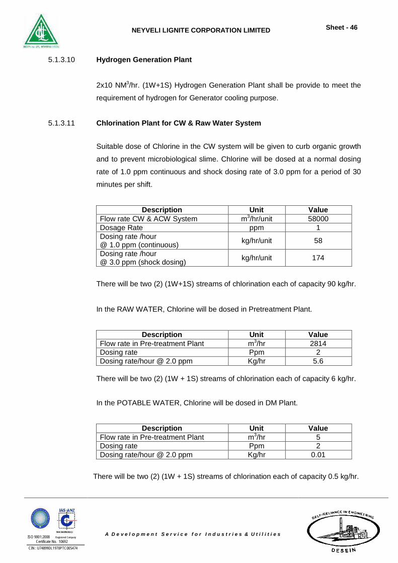
NEYVELI LIGNITE CORPORATION LIMITED
Sheet - 46
ISO 9001:2008 Registered Company Certificate No. 10692
CIN : U74899DL1970PTC005474
A D e v e l o p m e n t S e r v i c e f o r I n d u s t r i e s & U t i l i t i e s
5.1.3.10 Hydrogen Generation Plant 2x10 NM3/hr. (1W+1S) Hydrogen Generation Plant shall be provide to meet the
requirement of hydrogen for Generator cooling purpose.
5.1.3.11 Chlorination Plant for CW & Raw Water System
Suitable dose of Chlorine in the CW system will be given to curb organic growth
and to prevent microbiological slime. Chlorine will be dosed at a normal dosing
rate of 1.0 ppm continuous and shock dosing rate of 3.0 ppm for a period of 30
minutes per shift.
Description Unit Value Flow rate CW & ACW System m3/hr/unit 58000 Dosage Rate ppm 1 Dosing rate /hour @ 1.0 ppm (continuous) kg/hr/unit 58
Dosing rate /hour @ 3.0 ppm (shock dosing) kg/hr/unit 174
There will be two (2) (1W+1S) streams of chlorination each of capacity 90 kg/hr.
In the RAW WATER, Chlorine will be dosed in Pretreatment Plant.
Description Unit Value Flow rate in Pre-treatment Plant m3/hr 2814 Dosing rate Ppm 2 Dosing rate/hour @ 2.0 ppm Kg/hr 5.6
There will be two (2) (1W + 1S) streams of chlorination each of capacity 6 kg/hr.
In the POTABLE WATER, Chlorine will be dosed in DM Plant.
Description Unit Value Flow rate in Pre-treatment Plant m3/hr 5 Dosing rate Ppm 2 Dosing rate/hour @ 2.0 ppm Kg/hr 0.01
There will be two (2) (1W + 1S) streams of chlorination each of capacity 0.5 kg/hr.
NEYVELI LIGNITE CORPORATION LIMITED
Sheet - 47
ISO 9001:2008 Registered Company Certificate No. 10692
CIN : U74899DL1970PTC005474
A D e v e l o p m e n t S e r v i c e f o r I n d u s t r i e s & U t i l i t i e s
5.1.3.12 Circulating Water System
Closed cycle condenser cooling is envisaged for cooling water system with
Natural Draft Cooling Tower (NDCT). The CW sump will be provided with Five
(5) nos. (4W+1S) 50% CW pumps of two units for pumping Cooling Water to the
Condenser and thereafter shall be discharged into NDCT having cooling range of
10oC, maintaining cycle of concentration at 3.0. To maintain 3 C.O.C. in C.W.
system chemical treatment will be carried out.
5.1.3.13 Auxiliary Cooling Water System
The ACW system meets the cooling water requirements of all the auxiliary
equipment of the TG and SG units such as turbine lube oil coolers, generator air
cooler, Vacuum pump, ash cooler, exciter air coolers, Seal Pot, ID/SA/PA fan
bearing oil coolers, BFP auxiliaries such as lube oil coolers, working oil coolers,
drive motors, etc., condensate pump bearings, sample coolers, air compressors
and ash handling system compressors, etc.
5.1.3.14 Natural Draft Cooling Tower
It is proposed to install Natural draft cooling tower of capacity 60,900 m³/hr/unit
for condenser cooling water and auxiliary cooling water.
5.1.3.15 Flue Gas Desulphurization (FGD) System
The FGD system shall be provided to treat gases produced from the combustion
of any and all fuels – Fuel Properties. The FGD system shall be limestone
scrubber with a proven design & shall be capable of meeting plant emission
requirement to prevent a visible stack plume and MOEF requirement i.e.
Particulate Matter - 30 mg/Nm3
Sulphur Dioxide (So2) - 100 mg/Nm3
Oxide of Nitrogen (Nox) - 100 mg/Nm3
Mercury (Hg) - 0.03 mg/Nm3
NEYVELI LIGNITE CORPORATION LIMITED
Sheet - 48
ISO 9001:2008 Registered Company Certificate No. 10692
CIN : U74899DL1970PTC005474
A D e v e l o p m e n t S e r v i c e f o r I n d u s t r i e s & U t i l i t i e s
The limestone based FGD system shall be furnished complete with necessary
pumps, piping and valves, control and instrumentation and moisture separators
for the flue gas.
FGD system shall be designed to remove SO2 for all load conditions from
minimum continuous through BMCR to meet the limits.
FGD system shall be designed and constructed to operate as specified at
maximum continuous rated load 24 hours per day, 7days per week, 365 days per
year, except during unit outages. Particulate matter in the flue gas leaving the
boiler shall be removed by ESP.
FGD system shall include an emergency water quench system to protect
absorber module, linings, and internals from damage in the event of loss of water
to scrubber module at normal flue gas temperature for a period of 30 minutes.
The control system shall be DCS-based with dual redundant data links utilizing
MODBOUS protocol for interface with plant DCS.
5.1.3.16 Effluent Disposal System
The waste water treatment system shall be designed to collect waste water from
all sources in the power plant and provide treatment to enable it to be reused in
the power plant to achieve Zero Discharge as far as possible. The quality of
effluent shall conform to norms stipulated by Local Pollution Board.
The sources of plant effluent are mainly:
a. CT Blow Down
b. Plant drains and boiler blow down
c. Oily waste
d. DM Plant waste
CTBD waste will be treated in Pre-filter, ultra-filtration & reverse osmosis in
order to make it suitable for CW make-up.
NEYVELI LIGNITE CORPORATION LIMITED
Sheet - 49
ISO 9001:2008 Registered Company Certificate No. 10692
CIN : U74899DL1970PTC005474
A D e v e l o p m e n t S e r v i c e f o r I n d u s t r i e s & U t i l i t i e s
All the above effluent except CT Blow Down shall be pumped to the Central
Monitoring Basin.
The Central Monitoring Basin shall have two (2) compartments, each
compartment having adequate storage to collect a day’s effluents. Facilities in
the form of chemical dosing system, effluent recirculation system, etc. shall be
provided to treat the effluent and to bring the quality suitable for reuse in ash
handling plant, along with the ETP waste. Necessary instruments shall be
provided for monitoring the quality of effluents.
5.1.3.17 Rain Water Harvesting System
Rain water harvesting is the process of collecting, conveying and storing water
from an area that has been treated to increase the runoff of rainfall. The
potential of Rain water harvesting can be illustrated by pointing out that 1
millimeter of rain equals 10,000 litre of water per hectare. A small area of
impermeable surface can collect a relatively large volume of water. The most
important components, which will be evaluated for designing the rain water
harvesting structure, are:
Hydrogeology of the plant area including nature and extent of aquifer, soil
cover, topography, depth of water levels and chemical availability of
ground water.
Areas contributing for runoff i.e. how much area and land use pattern
wither plant area, colony area or green belts and general built up pattern
of the area.
Hydro - metrological characters like rainfall duration, general pattern and
intensity of rainfall.
The following portions are excluded from the rainwater catchment area, as
rainfall in these areas are either do not come out that can be dealt with or rainfall
comes out as inefficient and these are dealt separately.
NEYVELI LIGNITE CORPORATION LIMITED
Sheet - 50
ISO 9001:2008 Registered Company Certificate No. 10692
CIN : U74899DL1970PTC005474
A D e v e l o p m e n t S e r v i c e f o r I n d u s t r i e s & U t i l i t i e s
Cooling Tower
Guard Pond / RWHP areas
Coal Stock Pile Area
Boiler / ESP area
Fuel oil handling and storage area
5.1.3.18 Sewage Treatment Plant
The sanitary waste streams from the different buildings of the plant will flow
under gravity through their respective manholes. The sewage will flow from the
manholes to the nearest collection chambers by gravity. The collected sewage in
the collection chambers will flow through sewer lines and flow to the common
collection sump. From the common collection sump the sewage will be pumped
to the equalization Tank located in the STP Area.
The sewage treatment plant will be designed as per guidelines of CPHEEO
Manual. The anticipated no. of users will be 1000 persons. The sewage
treatment plant will be designed to handle a flow of 40 KLD considering average
per capita consumption of 45 Ipcd with 80% of used water generated as sewage.
The Sewage Treatment Plant will be modular type based on FAB/MBBR
technology followed by disinfection by Hypo and necessary tertiary treatment
prior to reuse in horticulture purpose.
The major areas as sources of sanitary waste water will be:
i) STG Building
ii) Service Building
iii) Transformer Yard
iv) Switch Yard
v) Compressed Air Building / DG Room
vi) ESP Control Room
vii) CW & ACW Pump House
viii) Canteen
ix) Workshop Building
x) Fire Station Building
NEYVELI LIGNITE CORPORATION LIMITED
Sheet - 51
ISO 9001:2008 Registered Company Certificate No. 10692
CIN : U74899DL1970PTC005474
A D e v e l o p m e n t S e r v i c e f o r I n d u s t r i e s & U t i l i t i e s
xi) DM Plant & N. Pit
xii) Fuel Oil Pump House & Tank Area
xiii) Crusher House
xiv) CHP Control Room
xv) Raw Water Pump House
xvi) Ware House
xvii) Security & Time Office
xviii) Maintenance Building
5.1.3.19 Chemical Laboratory
A central chemical laboratory adjacent to DM Plant building is envisaged for the
station. This will have necessary equipment and facilities to test and analyze
steam, water, oil, fuel etc. required to ensure satisfactory operation &
maintenance of steam generator.
NEYVELI LIGNITE CORPORATION LIMITED
Sheet - 52
ISO 9001:2008 Registered Company Certificate No. 10692
CIN : U74899DL1970PTC005474
A D e v e l o p m e n t S e r v i c e f o r I n d u s t r i e s & U t i l i t i e s
5.2 ELECTRICAL SYSTEM
5.2.1 Basic Design Concepts The electrical system will be designed to ensure high reliability of operation and
high availability of the power plant through use of proven equipment conforming
to International Standards, Codes and Practices and adequate level of
redundancy. The electrical systems & equipments will be specified to comply
with the guide lines issued / notified by Indian Statutory Authorities viz. the
Central Electricity Authority (CEA), Central Board of Irrigation & Power (CBIP),
Indian Electricity (IE) Rules & Act, National Electrical Code (NEC), etc.
Station Electrical systems and equipment will be designed conforming to the
following basic concepts:-
a) Ambient temperature: The equipment will be designed for a maximum
ambient temperature of 50°C.
b) Voltage levels: Voltage levels envisaged at the plant are 400 kV & 230kV
for evacuation of power & startup power; 20-24 kV for generation; 11 KV
for motors rated above 750kW, 3.3 kV for motors rated above 160 kW &
rated up to 750 kW, 415 Volts for small auxiliaries (rated up to 160 kW)
and 220 Volts DC. Single-phase AC motors are not recommended for
use.
c) Variations: Auxiliaries will be designed for ac voltage variation of +10%,
frequency variation of +5%; and combined voltage and frequency
variation is 10%. DC auxiliary voltage variation is (-) 15% to (+)10% of
220Volts.
d) Fault levels: Symmetrical fault level ratings and withstand duration at the
various voltage levels for design of circuit breakers and other components
are as under:
NEYVELI LIGNITE CORPORATION LIMITED
Sheet - 53
ISO 9001:2008 Registered Company Certificate No. 10692
CIN : U74899DL1970PTC005474
A D e v e l o p m e n t S e r v i c e f o r I n d u s t r i e s & U t i l i t i e s
i) 400 kV - 50 kA (rms) for 1 second
ii) 230 kV - 40 kA (rms) for 1 second
iii) 11 KV - 50 kA (rms) for 1 second
iv) 3.3 kV - 40 kA (rms) for 1 second
v) 415 Volt - 50 kA (rms) for 1 second
e) Basic insulation level: Lightning impulse levels of 1425 kV (peak) for 400
kV system. 1050 kVp for 230 kV, 125 kVp for 20-24 kV, 75 kVp for 11 kV
system, 40 kVp for 3.3 kV system and 5kVp for 415V system will be
adopted.
f) In line with the prevailing practices, neutrals of 400 kV, 230 kV and 415 V
ac systems will be solidly grounded. Generator neutrals will be grounded
with resistance loaded distribution transformer. 11 KV and 3.3 kV system
neutrals will be grounded through resistance limiting the earth-fault
current to 300 Amps. 220V DC system will have a floating (unearthed)
neutral.
g) Control and Protection: Controls will be micro-processor based and
centralized in a central control room. Multifunction numerical type relays
with redundant features will be used as far as possible for the protection
of generators, transformers, 400 kV, 230 kV, 20-24 kV, 11 kV, 3.3 kV and
415V systems.
5.2.2 Generator
Generators will be directly-coupled to the steam turbines and shall be two-pole type
alternator having direct hydrogen-cooled stator core & rotor and demineralised
water-cooled & vacuum pressure impregnated stator winding. The generator
excitation system will be rotating diode, brushless type with a permanent magnet
generator (PMG) or Static Excitation system as per manufactures standard.
To maintain and control the generator terminal voltage under various operating
conditions and external faults, a digital multi-channel automatic voltage regulator
(DAVR) will be provided.
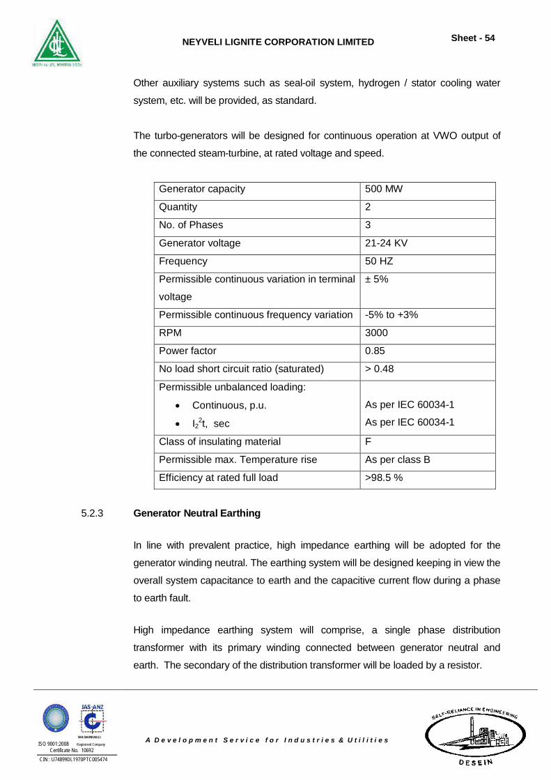
NEYVELI LIGNITE CORPORATION LIMITED
Sheet - 54
ISO 9001:2008 Registered Company Certificate No. 10692
CIN : U74899DL1970PTC005474
A D e v e l o p m e n t S e r v i c e f o r I n d u s t r i e s & U t i l i t i e s
Other auxiliary systems such as seal-oil system, hydrogen / stator cooling water
system, etc. will be provided, as standard.
The turbo-generators will be designed for continuous operation at VWO output of
the connected steam-turbine, at rated voltage and speed.
Generator capacity 500 MW
Quantity 2
No. of Phases 3
Generator voltage 21-24 KV
Frequency 50 HZ
Permissible continuous variation in terminal
voltage
± 5%
Permissible continuous frequency variation -5% to +3%
RPM 3000
Power factor 0.85
No load short circuit ratio (saturated) > 0.48
Permissible unbalanced loading:
Continuous, p.u.
I22t, sec
As per IEC 60034-1
As per IEC 60034-1
Class of insulating material F
Permissible max. Temperature rise As per class B
Efficiency at rated full load >98.5 %
5.2.3 Generator Neutral Earthing
In line with prevalent practice, high impedance earthing will be adopted for the
generator winding neutral. The earthing system will be designed keeping in view the
overall system capacitance to earth and the capacitive current flow during a phase
to earth fault.
High impedance earthing system will comprise, a single phase distribution
transformer with its primary winding connected between generator neutral and
earth. The secondary of the distribution transformer will be loaded by a resistor.
NEYVELI LIGNITE CORPORATION LIMITED
Sheet - 55
ISO 9001:2008 Registered Company Certificate No. 10692
CIN : U74899DL1970PTC005474
A D e v e l o p m e n t S e r v i c e f o r I n d u s t r i e s & U t i l i t i e s
5.2.4 Generator Bus Duct
The terminals of the generator would be connected to the respective generator
transformer (GT) LV on the line side and to star formation &neutral earthing
cubicle through Isolated Phase Bus Ducts (IPBD) of adequate short circuit
withstand capability with suitably rated tap-offs to the unit transformers and
Surge Protection & Voltage Transformer(SPVT) cubicle. The short circuit rating
of the main run will correspond to higher of the fault current contributions from
generator or transformer side while the tap-offs and delta connection will be
designed for sum of the fault contributions from generator and GT side. The fault
withstand time rating of the busduct will correspond with the de-excitation time of
the generator. The bus duct will be natural air cooled, pressurized type and will
run partly indoor and partly outdoor.
The bus duct installation would be complete with generator line side and neutral
side current transformers and line side voltage transformers required for
protection, metering, voltage regulation and automatic turbine run-up system.
Surge protection equipments consisting of lightning surge arrestors & capacitors
with suitable discharge characteristics to suit the generator basic insulation level
shall be provided.
5.2.5 Single Line Diagram
A Key Single Line Diagram of Electrical System and SLD for 400kV GIS & 230kV
GIS for the proposed 2 x 500 MW Power Plant is placed as Annexure-6.5.
5.2.6 Power Evacuation
The total power generated by the power plant will be 1000MW (2x500MW). After
meeting auxiliary power consumption of about 60MW (6%), 940MW (1106 MVA
at 0.85 pf) will be available for export. Generated power will be at a voltage level
of 21-24kV as per manufacturer’s standard voltage at the generator terminals.
NEYVELI LIGNITE CORPORATION LIMITED
Sheet - 56
ISO 9001:2008 Registered Company Certificate No. 10692
CIN : U74899DL1970PTC005474
A D e v e l o p m e n t S e r v i c e f o r I n d u s t r i e s & U t i l i t i e s
The initial power required for startup shall be taken from 230kV sub station
through a 230kV line feeder which shall be connected to 230/11kV station
transformer as shown in the Single Line Diagram.
5.2.7 SWITCHYARD
400kV and 230kV gas insulated switchyard (GIS) have been considered as per
the attached SLD to facilitate power evacuation to state transmission utility (STU)
and PGCIL.
400kV Switchyard 400kV gas insulated indoor switchyard will be provided to evacuate power to
PGCIL. Each generator will be connected to the 400kV switchyard through a
generator transformer.
One & half breaker arrangement will be adopted for the switchyard. The following
will be connected to the switchyard:
2 Nos. generator transformer feeders
2 Nos. of 400/220kV ICT
4 Nos. outgoing line feeders (The actual number of outgoing line feeders and
quantum of switched line reactors, if any, will be based on grid authority
requirements)
2 Nos. bus reactor feeders (The actual number of bus reactors and reactor
ratings will be based on grid authority requirements)
The switchyard will be provided with necessary current transformers, surge
arrestors, protective relays, metering etc. Tariff metering will be provided with
separate metering panel. Tariff energy meters will have accuracy class of 0.2S
and will have facility for CT accuracy compensation. Dedicated instrument
transformers (CT of 0.2S class and EMVT of 0.2 class) will be provided for tariff
metering system.
The tariff meters will be ABT compatible static tri-vector meters suitable for 3
phase 4 wire system. Following meters will be provided:
NEYVELI LIGNITE CORPORATION LIMITED
Sheet - 57
ISO 9001:2008 Registered Company Certificate No. 10692
CIN : U74899DL1970PTC005474
A D e v e l o p m e n t S e r v i c e f o r I n d u s t r i e s & U t i l i t i e s
Main meter and check meter (import / export) for each 400 kV line
Standby meter on EHV side of each generator transformer
ABT meters for each UT and Excitation Transformer
In addition, OPGW will be provided. OPGW will conform to grid authority
requirements.
220kV SWITCHYARD
220kV gas insulated indoor switchyard will be provided to evacuate power to
STU and as well as for the start up power.
Double bus bar arrangement will be adopted for the switchyard. The following will
be connected to the switchyard:
2 Nos. station transformer feeders
2 Nos. of 400/220kV ICT
4 Nos. outgoing line feeders (The actual number of outgoing line feeders
and quantum of switched line reactors, if any, will be based on grid
authority requirements)
1 No. Bus coupler bay
The switchyard will be provided with necessary current transformers, surge
arrestors, protective relays, metering etc. Tariff metering will be provided with
separate metering panel. Tariff energy meters will have accuracy class of 0.2S
and will have facility for CT accuracy compensation. Dedicated instrument
transformers (CT of 0.2S class and EMVT of 0.2 class) will be provided for tariff
metering system.
The tariff meters will be ABT compatible static tri-vector meters suitable for 3
phase 4 wire system. Following meters will be provided:
Main meter and check meter (import / export) for each 220kV line
Standby meter on EHV side of each station transformer
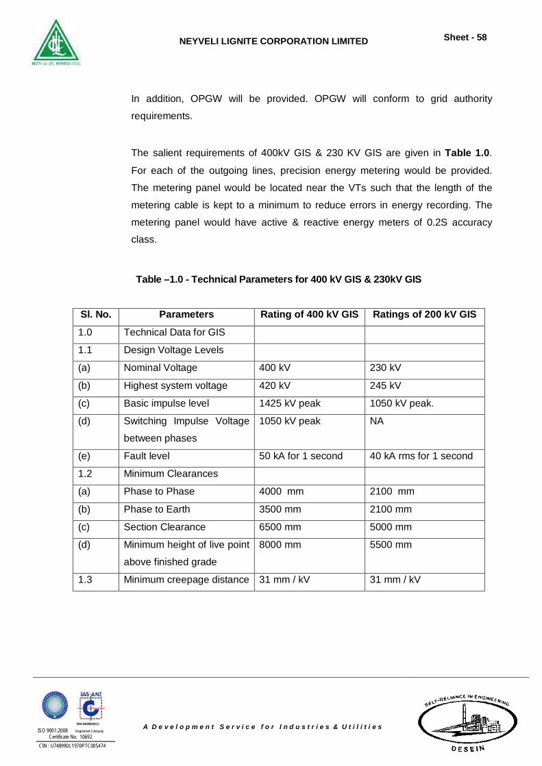
NEYVELI LIGNITE CORPORATION LIMITED
Sheet - 58
ISO 9001:2008 Registered Company Certificate No. 10692
CIN : U74899DL1970PTC005474
A D e v e l o p m e n t S e r v i c e f o r I n d u s t r i e s & U t i l i t i e s
In addition, OPGW will be provided. OPGW will conform to grid authority
requirements.
The salient requirements of 400kV GIS & 230 KV GIS are given in Table 1.0.
For each of the outgoing lines, precision energy metering would be provided.
The metering panel would be located near the VTs such that the length of the
metering cable is kept to a minimum to reduce errors in energy recording. The
metering panel would have active & reactive energy meters of 0.2S accuracy
class.
Table –1.0 - Technical Parameters for 400 kV GIS & 230kV GIS
Sl. No. Parameters Rating of 400 kV GIS Ratings of 200 kV GIS
1.0 Technical Data for GIS
1.1 Design Voltage Levels
(a) Nominal Voltage 400 kV 230 kV
(b) Highest system voltage 420 kV 245 kV
(c) Basic impulse level 1425 kV peak 1050 kV peak.
(d) Switching Impulse Voltage
between phases
1050 kV peak NA
(e) Fault level 50 kA for 1 second 40 kA rms for 1 second
1.2 Minimum Clearances
(a) Phase to Phase 4000 mm 2100 mm
(b) Phase to Earth 3500 mm 2100 mm
(c) Section Clearance 6500 mm 5000 mm
(d) Minimum height of live point
above finished grade
8000 mm 5500 mm
1.3 Minimum creepage distance 31 mm / kV 31 mm / kV
NEYVELI LIGNITE CORPORATION LIMITED
Sheet - 59
ISO 9001:2008 Registered Company Certificate No. 10692
CIN : U74899DL1970PTC005474
A D e v e l o p m e n t S e r v i c e f o r I n d u s t r i e s & U t i l i t i e s
Switchyard Power Supply
The following power supply systems are proposed for switchyard equipment and
switchyard lighting:
415V Normal Auxiliary Power Supply
One number normal power distribution board (PDB) with two incomers and bus
coupler will be provided. Auto/ manual changeover scheme will be provided with
interlocking of PDB incomer with upstream breaker.
415V Emergency Auxiliary Power Supply
One number emergency PDB with two incomers will be provided. One incomer
will be connected to the normal PDB and the other incomer will be connected to
the plant emergency switchboard. The two incomers will be interlocked such that
only one incomer can be in closed position at a time.
220V DC Supply
One number 220V DC distribution board deriving supply from dedicated 220V
system for switchyard will be provided.
5.2.8 Control System
Control of Switchyard
Switchyard will be controlled from Substation Automation System (SAS) through
a dedicated Video Display Unit (VDU) in the switchyard control room. In addition,
VDU for switchyard will be provided in the main plant control room. The controls
will be through mimic screens in the VDU. All switchyard I/O signals will be
terminated in a marshalling panel/remote I/O panel located in the switchyard
control room. Sequence event recording / status of brakers and fault reporting of
switchyard as well as important analogue signals will be indicated in SAS.
NEYVELI LIGNITE CORPORATION LIMITED
Sheet - 60
ISO 9001:2008 Registered Company Certificate No. 10692
CIN : U74899DL1970PTC005474
A D e v e l o p m e n t S e r v i c e f o r I n d u s t r i e s & U t i l i t i e s
The SAS will be interconnected with the plant DCS system to facilitate monitoring
of switchyard signals from the main plant control room.
Control of Plant Electrical
The complete electrical system of power plant will be controlled and monitored
from the plant DCS system. The controls for the following will be through mimic
screens in VDU.
22kV/ generation voltage system
11 kV system
3.3 kV system
415V system
Critical signals, analogue signals, status alarms and controls of the switchgears
will be extended to DCS system.
Sequence event recording / status of breakers and fault reporting of various plant
voltage systems, diesel generator, 220V DC system etc. will be indicated in the
plant DCS system.
Control of all motors will be from DCS only. All breaker controlled feeders in the
main plant area will be controlled from DCS. No backup control panel is
envisaged for the plant electrical power distribution.
Synchorizing facility will be provided in Generator Control Panel. For 11 kV unit /
station switchboards, synchronizing facility will be provided in Bus Transfer
Panel.
For off-site areas, controls will be provided in respective PLC or directly in the
switchboard itself.
Unit transformers and station transformers will have OLTC control.
NEYVELI LIGNITE CORPORATION LIMITED
Sheet - 61
ISO 9001:2008 Registered Company Certificate No. 10692
CIN : U74899DL1970PTC005474
A D e v e l o p m e n t S e r v i c e f o r I n d u s t r i e s & U t i l i t i e s
5.2.9 Energy Management System
Energy Management System consisting of all hardware and software with inputs
from DLC/PLC/SAS/Data Concentrator/Serial Server through OPC link with
necessary cabling system shall be provided.
5.2.10 Auxiliary Power Supply
For each 500 MW unit, two (2) x 50% capacity steam turbine driven boiler feed
pumps(TDBFPs) and one (1)x 50% capacity electric motor driven boiler feed pump
(MDBFP) are envisaged. Further, the cooling tower is proposed to be natural draft
type.
During start up of the unit as also during outage of one of the TDBFPs, the
MDBFP will be running on full load. As per CERC norms, the auxiliary power
requirement of a thermal power plant having electric motor driven BFPs and
natural draft cooling towers is to be considered as 8.5% of the generated power
i.e. about 42.5 MW (53.125 MVA at an average power factor of 0.8) for each
500MW plant.
Various auxiliaries would be supplied at the following nominal voltages
depending upon their ratings and functions:
a) 11000 V 10%, 50 Hz 5%, 3 phase, 3 wire, resistance grounded AC
supply for motors rated above 750 kW.
b) 3300 V 10%, 50 Hz 5%, 3 phase, 3 wire, resistance grounded AC
supply for motors rated above 160 kW and upto 750 kW.
c) 415 V, 10%, 50 Hz 5%, 3 phase, 3 wire, solidly grounded AC supply
for motors rated 160 kW and below and other L.V. services
d) 230 V, 10%, 50 Hz 5%, 1 phase AC supply for lighting, space
heating of motors and panels, single phase motors, etc.
220 V, ungrounded DC supply for protection, control and indication.
NEYVELI LIGNITE CORPORATION LIMITED
Sheet - 62
ISO 9001:2008 Registered Company Certificate No. 10692
CIN : U74899DL1970PTC005474
A D e v e l o p m e n t S e r v i c e f o r I n d u s t r i e s & U t i l i t i e s
5.2.11 Construction Power
Construction power to the tune of 2.5–5 MW is expected to be required during
various phases of construction. Since this is a green-field site, a reliable source of
construction power will need to be provided.
It is proposed to step down the available 33kV supply to 11 kV by 2 Nos. suitably
rated (approx. 5 MVA) 33/11 kV step down transformer Construction power supply
shall be provided at 11 kV voltage level.
5.2.12 Generator Transformers
The Generator Transformer for each 500 MW unit will comprise three (3) single
(1) phase units, 200 MVA OFAF/ONAF/ONAN cooled oil-immersed outdoor type
with class 'A' insulation. The low voltage side of the transformer will have isolated
phase bus duct connection to the generator while the high voltage side will be
connected to the 400 KV Switchyard by means of ACSR overhead conductors.
Voltage ratio for the GTs will be (420/3)/21kV. Each Transformer will be
provided with off circuit taps of +/-5% in steps of 2.5%. The three phase
windings of the transformer will be connected in star on HV with neutral brought
out for solid grounding. The secondary windings will be connected in delta. The
vector group will be Ynd11.
Each transformer will be provided with a lightning surge arrester on each phase.
One single phase unit will be provided as common standby for the two GTs and
will be suitably placed in the transformer yard.
5.2.13 Station Auxiliary Transformers for Startup Power
Startup power for the Units will be obtained from 230 kV system through 3 phase,
three winding 400/11.5/11.5 kV, 90/45/45 MVA OFAF/ONAF/ ONAN cooled
station transformer. Two (2) nos. Station Transformers, will supply power to 11
kV station buses. OLTC in the range +10% and in steps of 1.25% will be
NEYVELI LIGNITE CORPORATION LIMITED
Sheet - 63
ISO 9001:2008 Registered Company Certificate No. 10692
CIN : U74899DL1970PTC005474
A D e v e l o p m e n t S e r v i c e f o r I n d u s t r i e s & U t i l i t i e s
provided on HV side of the station transformer to maintain constant voltage on 11
kV buses.
5.2.14 Unit Transformers
Two (2) 3-phase transformers of 21/11kV Dyn1, 40 MVA rated with ONAN/ ONAF
cooling will be provided for each unit to supply unit auxiliary loads viz. boiler and
turbine house auxiliaries & LT auxiliary transformers. OLTC will be provided on HV
winding of the UATs with 10% range in steps of 1.25% each for maintaining
constant voltage on the 11 kV side.
5.2.15 Unit AuxiliaryTransformers and Other Auxiliary Transformers
Auxiliary transformers will be provided to cater power for 3.3Kv switchgear and will
be derived from 11Kv switchgear. The unit auxiliary transformer ratio shall be rated
for 16 MVA, 11/3.45Kv. For reliability 2X100% rated transformers are envisaged and
fed from two separate 11 kV sources. These transformers will be 3 phase, 2 winding,
delta/star connected (Dyn11) with OCTC, outdoor type and oil filled with natural air
cooling. LV side neutral will be grounded though resistor limiting the earth fault
current to about 300A.
5.2.16 Service Transformers
Required number of service transformers would be provided to feed power to LV
loads depending on service/ location of the loads. These transformers would be
rated at not more than 2.5 MVA, dry type, 11 / 0.433 kV. They would supply power
to the 415 V auxiliaries of the unit, Cooling water system, Water treatment plant, Ash
handling system, Lignite handling system etc., the neutrals of these transformers
would be solidly earthed. The transformers would be provided with + / - 5% off-
circuit taps in steps of 2.5% on the HV side.
5.2.17 HV Switchgear
The voltage level of HV Switchgear will be 11 kV and 3.3 kV. The HV switch gear
would comprise draw-out type vacuum circuit breakers housed in indoor, metal-
NEYVELI LIGNITE CORPORATION LIMITED
Sheet - 64
ISO 9001:2008 Registered Company Certificate No. 10692
CIN : U74899DL1970PTC005474
A D e v e l o p m e n t S e r v i c e f o r I n d u s t r i e s & U t i l i t i e s
clad cubicles and would cater to all motors rated above 160 kW up to 750 kW
(3.3 kV) and motors rated above 750 kW (11 kV). The switch gears would be
equipped with control, protection, interlock and metering features as required.
Separate 11 KV, 3.3 kV switchgears would also be provided for the raw water
intake system, lignite and ash handling systems and external lignite handling
system. Fast auto change over feature would be provided between two sources
of supply.
5.2.18 LV Switchgear
415V, 3 phase, 3 wire/4 wire power for LV auxiliaries would be obtained from 11
kV/0.433 kV service transformers. The 415V system would be a solidly earthed
system. For maximum reliability, duplicate power supplies with auto changeover
facility would be provided for all power and motor control centres. The 415V
switch gear would be of metal enclosed design with a minimum symmetrical
short circuit rating of 50 kA for 1 sec. All power and motor control centres would
be compartmentalised and would be of double front execution. They would be of
fully draw-out design with all circuit components mounted on a withdrawable
sheet metal chassis. The circuit breakers would be of air break/MCCB/MPCB
type. Motor starting would be direct-on-line. MCCBs/MPCBs shall be used
instead of HRC fuses for all LV switchgear.
“All LV motors would be controller by air break, electro-magnetic type contactors,
Intelligent controllers associated with current measuring modules and suitably
rated MPCBs, and MCCBs”.
5.2.19 Motors HV & LV motors shall be energy efficient level IE 3 type as per IS 12615: 2011,
F class insulated with maximum temperature rise within class ‘B’ limits, having
IP-55 enclosure protection (with canopy for outdoor motors), designed for
direct-on-line starting with as low starting current as possible. Starting current of
motors will be designed so as not to pose a problem in starting or cause drop out
of running auxiliaries.
NEYVELI LIGNITE CORPORATION LIMITED
Sheet - 65
ISO 9001:2008 Registered Company Certificate No. 10692
CIN : U74899DL1970PTC005474
A D e v e l o p m e n t S e r v i c e f o r I n d u s t r i e s & U t i l i t i e s
The motor rating shall be arrived at considering 15% margin over the duty point
input or 10% over the maximum demand of the driven equipment, whichever is
higher, considering highest system frequency.
All motors shall be either totally enclosed fan cooled (TEFC) or totally enclosed
tube ventilated (TETV) or Closed air circuit air cooled (CACA) type. However,
motors rated 3000KW or above can be Closed air circuit water cooled (CACW).
CW motors can be screen protected drip proof (SPDP) type.
HV motors shall also be capable of satisfactory operation at full load at a supply
voltage of 80% of the rated voltage for 5 min. commencing from hot condition.
Motor torque characteristic will be such as to ensure smooth and rapid starting
and acceleration of the driven equipment.
Motors rated above 30 kW will be provided with space heaters to be switched on
when the motor is idle.
5.2.20 Metering
Microprocessor based multi-function 0.2s class energy meters with
communication facilities, non-volatile memory, MMI and self-diagnostic facilities
shall be provided for all, generators, HV side of GT, STs & UTs, SUT, in line with
notified CEA standards.
Incomers, tie feeders, outgoing transformer& motor feeders on all 11 kV and 3.3
kV station and unit switchgears will be equipped with multifunctional
microprocessor based feeder management devices having protection and
metering facilities alongwith ports for interface with plant DDC MIS system.
All other feeders will be provided with conventional indicating and metering
instruments.
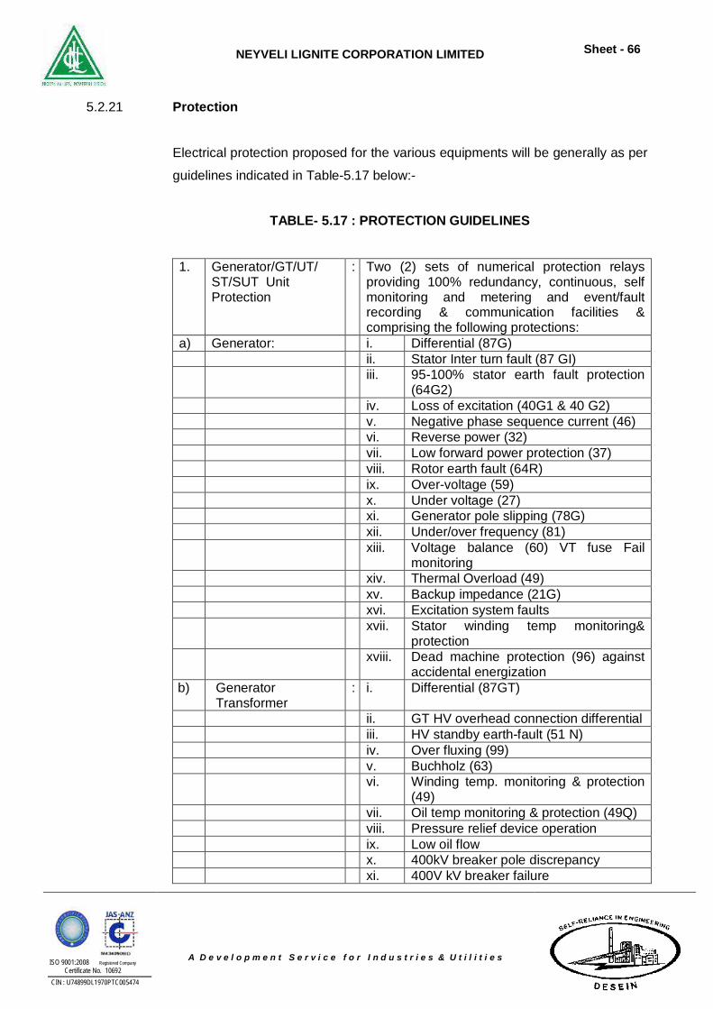
NEYVELI LIGNITE CORPORATION LIMITED
Sheet - 66
ISO 9001:2008 Registered Company Certificate No. 10692
CIN : U74899DL1970PTC005474
A D e v e l o p m e n t S e r v i c e f o r I n d u s t r i e s & U t i l i t i e s
5.2.21 Protection
Electrical protection proposed for the various equipments will be generally as per
guidelines indicated in Table-5.17 below:-
TABLE- 5.17 : PROTECTION GUIDELINES
1. Generator/GT/UT/ ST/SUT Unit Protection
: Two (2) sets of numerical protection relays providing 100% redundancy, continuous, self monitoring and metering and event/fault recording & communication facilities & comprising the following protections:
a) Generator: i. Differential (87G) ii. Stator Inter turn fault (87 GI) iii. 95-100% stator earth fault protection
(64G2) iv. Loss of excitation (40G1 & 40 G2) v. Negative phase sequence current (46) vi. Reverse power (32) vii. Low forward power protection (37) viii. Rotor earth fault (64R) ix. Over-voltage (59) x. Under voltage (27) xi. Generator pole slipping (78G) xii. Under/over frequency (81) xiii. Voltage balance (60) VT fuse Fail
monitoring xiv. Thermal Overload (49) xv. Backup impedance (21G) xvi. Excitation system faults xvii. Stator winding temp monitoring&
protection xviii.
Dead machine protection (96) against accidental energization
b) Generator Transformer
: i. Differential (87GT)
ii. GT HV overhead connection differential iii. HV standby earth-fault (51 N) iv. Over fluxing (99) v. Buchholz (63) vi. Winding temp. monitoring & protection
(49) vii. Oil temp monitoring & protection (49Q) viii. Pressure relief device operation ix. Low oil flow x. 400kV breaker pole discrepancy xi. 400V kV breaker failure
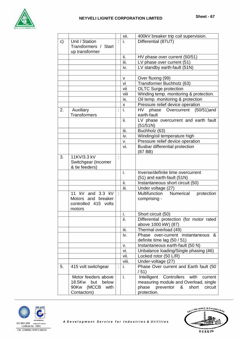
NEYVELI LIGNITE CORPORATION LIMITED
Sheet - 67
ISO 9001:2008 Registered Company Certificate No. 10692
CIN : U74899DL1970PTC005474
A D e v e l o p m e n t S e r v i c e f o r I n d u s t r i e s & U t i l i t i e s
xii. 400kV breaker trip coil supervision. c) Unit / Station
Transformers / Start up transformer
: i. Differential (87UT)
ii. HV phase over current (50/51) iii. LV phase over current (51) iv. LV standby earth-fault (51N) v Over fluxing (99) vi Transformer Buchholz (63) vii OLTC Surge protection viii Winding temp. monitoring & protection. ix. Oil temp. monitoring & protection x Pressure relief device operation 2. Auxiliary
Transformers : i. HV phase Overcurrent (50/51)and
earth-fault ii. LV phase overcurrent and earth fault
(51/51N) iii. Buchholz (63) iv. Winding/oil temperature high v. Pressure relief device operation vi. Busbar differential protection
(87 BB) 3. 11KV/3.3 kV
Switchgear (incomer & tie feeders)
:
i. Inverse/definite time overcurrent (51) and earth-fault (51N)
ii. Instantaneous short circuit (50) iii. Under voltage (27)
11 kV and 3.3 kV Motors and breaker controlled 415 volts motors
: Multifunction Numerical protection comprising -
i. Short circuit (50) ii. Differential protection (for motor rated
above 1000 kW) (87) iii. Thermal overload (49) iv. Phase over-current instantaneous &
definite time lag (50 / 51) v. Instantaneous earth-fault (50 N) vi. Unbalance loading/Single phasing (46) vii. Locked rotor (50 L/R) viii. Under-voltage (27) 5. 415 volt switchgear
: i. Phase Over current and Earth fault (50
/ 51) Motor feeders above 18.5Kw but below 90Kw (MCCB with Contactors)
i.
Intelligent Controllers with current measuring module and Overload, single phase preventor & short circuit protection.
NEYVELI LIGNITE CORPORATION LIMITED
Sheet - 68
ISO 9001:2008 Registered Company Certificate No. 10692
CIN : U74899DL1970PTC005474
A D e v e l o p m e n t S e r v i c e f o r I n d u s t r i e s & U t i l i t i e s
ii Phase current (for motors of rating 30 Kw and above)
7. Motor feeders upto 18.5Kw (MPCB with Contactors)
i Intelligent Controllers with current measuring module and overload & short circuit protection.
8 220 V DC System : i. Earth fault (Alarm only) ii. Under voltage (27) iii. Short circuit protection (by fuse)
5.2.22 Electrical Control Philosophy
A centralized control room will be provided at the operating floor of steam
turbine-generator building in which controls / control panels for the steam
generators, steam turbine generators, GT, UTs and distributed digital control
system (DDCMIS) equipment will be housed. In addition, auxiliary system
electrical relay panels and fire alarm control panel will also be provided in this
control room.
The control & synchronizing of generator, generator excitation system, GT, UTs
and auxiliary transformers, 11/3.3/0.415kV incomers, ties and main outgoing
circuit breakers to the auxiliaries will be also achieved from the keyboard of
DDCMIS Operator Control Stations in the Main Plant Control room.
5.2.23 Earthing System
The earthing requirement of the power station complex will be divided into the
following two main categories viz. System Earthing and Equipment Earthing:
a) System Earthing: The system neutral earthing at different voltage levels
has been described below:
Neutrals of 400 KV, 230kV and 415 V systems will be solidly earthed.
Generator neutrals will be earthed with resistance loaded distribution
transformer, 11 KV and 3.3 kV system neutral will be earthed through
high resistance limiting the earth-fault current to about 300 amps.
NEYVELI LIGNITE CORPORATION LIMITED
Sheet - 69
ISO 9001:2008 Registered Company Certificate No. 10692
CIN : U74899DL1970PTC005474
A D e v e l o p m e n t S e r v i c e f o r I n d u s t r i e s & U t i l i t i e s
b) Equipment Earthing: The equipment body earthing will be adopted to
provide protection to personnel from potentials caused by earth fault
currents and lightning discharges. A suitable earth grid will be provided for
earthing of equipment and structures maintaining the step and touch
potentials within safe limits. An earth mat will be laid in and around the
main power station. These mats will be buried at a suitable depth below
ground and balance of plant areas and provided with earth electrodes at
suitable spacing. The earth mats of main plant & BOP will be
interconnected by two or more interconnections. All metallic parts of
equipment supposed to be at earth potential will be connected to the
earthing mat including building structures, substation towers, plant rail
road tracks, perimeter fencing etc. The earthing system will comply with
IEEE 80, IEEE 665 and IS: 3043.
5.5.24 Lightning Protection System
Lightning protection system in accordance with IS: 2309 will be installed for
protection of tall buildings / structures and equipment against lightning discharge.
This will be achieved by providing lightning conductors on tall structures, stacks,
power house building, flood light towers etc. and connecting these with ground
electrodes.
5.2.25 Emergency Power Supply
To enable the unit to shutdown safely during complete A.C supply failure in the
station, certain important plant auxiliaries would be provided with a reliable A.C
power supply through a separate source. For this purpose, three (3) 415 V quick
starting diesel generator set with automatic mains failure (AMF) would be
provided. The rating of the DG sets would be approximately 1500 kVA for 500
MW unit. Further a third common DG set shall be taken as spare DG set for the
two units.
The diesel generator would feed emergency 415V switchgear, to which all the
essential loads such as the A.C emergency bearing lube oil and seal oil pumps,
NEYVELI LIGNITE CORPORATION LIMITED
Sheet - 70
ISO 9001:2008 Registered Company Certificate No. 10692
CIN : U74899DL1970PTC005474
A D e v e l o p m e n t S e r v i c e f o r I n d u s t r i e s & U t i l i t i e s
turning gear motor, battery chargers, emergency lights, elevators, fire alarms and
essential instrument power supply feeders would be connected. When the
station A.C supply is healthy, the emergency switchgear would be fed from the
unit service switch gear. When the station A.C supply fails, the DG set would
start automatically and would feed the loads connected to the emergency
switchgear. When the normal A.C supply is restored, these essential loads would
be manually changed over to the normal power supply.
5.2.26 Cables
Main factors considered for selection of power cable sizes will be as follows:-
System short circuit current withstand time of 0.16 seconds for circuit
breaker controlled feeders
Derating factors due to higher ambient temperature and grouping of cables.
Continuous current rating.
The voltage drop in the cable, during motor starting condition, shall be
limited to 15% and during full load running condition, shall be limited to 3 %
of the rated voltage.
The following types of cables would be used:
a) For 11 kV and 3.3 kV system: 11 kV and 3.3 kV unearthed grade
respectively, stranded aluminium conductor, cross linked polyethylene
(XLPE) insulated, “extruded FRLS PVC of Type-ST2” inner sheathed,
galvanised steel wire armoured for three core or aluminium wire
armoured for single core and overall FRLS extruded PVC of Type-
ST2” sheathed cables conforming to IS : 7098.
b) For medium and low voltage system: Power cables of 1100V grade,
stranded aluminium conductor, XLPE insulated, “extruded FRLS PVC
of Type- ST2” inner sheathed galvanised steel wire armoured for three
NEYVELI LIGNITE CORPORATION LIMITED
Sheet - 71
ISO 9001:2008 Registered Company Certificate No. 10692
CIN : U74899DL1970PTC005474
A D e v e l o p m e n t S e r v i c e f o r I n d u s t r i e s & U t i l i t i e s
cores or aluminium wire armoured for single core and overall “FRLS
extruded PVC of Type-ST2” sheathed cables conforming to IS : 7098.
c) For control applications: 1100 V grade annealed high conductivity
stranded copper conductor, insulated “Extruded PVC compound Type-
A” inner sheathed armoured and “FRLS Extruded PVC compound
Type-A” outer sheathed cables conforming to IS: 5831.
Cables would be laid in pre-fabricated steel ladder type or perforated type cable
trays in the station and other auxiliary buildings and upper elevations of the
steam generator area. Between buildings, the cables would be routed on pipe/
cable racks. Cables in outdoor switchyard would be laid in galvanised cable
trays in built-up trenches of suitable size.
5.2.27 DC System
Separate 2 x 100 %, 220 V DC rated batteries with associated float cum boost
chargers would be provided to cater emergency loads of main plant, lignite
handling system, ash handling system, 400 Kv/230 Kv GIS.
The batteries would be of stationary Lead acid Plante type complete with battery
racks, porcelain Insulators, inter-cell and inter-tier connectors.
Basis of selection of the above items will be as follows:-
i) Battery
Normal requirement of the battery is to supply power for the following:
* Control and monitoring of the entire power plant.
* Alarm and annunciation of plant condition under emergency. The
duty of the battery is strenuous particularly during the first one minute
NEYVELI LIGNITE CORPORATION LIMITED
Sheet - 72
ISO 9001:2008 Registered Company Certificate No. 10692
CIN : U74899DL1970PTC005474
A D e v e l o p m e n t S e r v i c e f o r I n d u s t r i e s & U t i l i t i e s
after occurrence of emergency. During this first minute, the battery is
required to supply.
* Tripping power for all major circuit breakers simultaneously.
* Starting of jacking oil pump.
* Starting of emergency lube oil pump.
* Starting of barring gear.
* Seal oil pump
* Plant emergency DC illumination system
* Indication, alarm and annunciation
After the lapse of the first minute, the demand on the battery will go down
considerably for the next 59 minutes during which the battery will only
serve all other loads mentioned above except that for the circuit breakers.
The duty cycle of the battery in this one-hour during the emergency
condition determines the battery capacity. The storage battery sets at its
rated discharge rate having suitable number of cells for 220 volts nominal
rating would be required. The ampere-hour capacity of each battery set
will also be determined by ageing factor, type of battery etc.
ii) Battery Charger
Battery chargers of suitable capacity will be provided with trickle charging
and boost charging for each of the aforesaid battery sets. The chargers
would be of silicon rectifier type with automatic voltage control and load
limiting features. Completely automatic and self-regulating type of battery
charger comprises of independent float cum boost chargers. The float
charger will be capable of floating the battery and at the same time supply
the continuous DC load. The boost charger will be capable of quick
NEYVELI LIGNITE CORPORATION LIMITED
Sheet - 73
ISO 9001:2008 Registered Company Certificate No. 10692
CIN : U74899DL1970PTC005474
A D e v e l o p m e n t S e r v i c e f o r I n d u s t r i e s & U t i l i t i e s
charging the battery and have a capacity to restore a fully discharged
battery to a state of fully charged condition in 8-10 hours and at the same
time supply the continuous DC load. 20% spare margin over the
maximum charging rate should be considered.
iii) DC Distribution Board
One main DC distribution board for each of the battery sets will be
provided with DC sub-distribution boards as required. The DC distribution
board will have two incomer DC switch-fuses and required number of
outgoing switch fuse units selected to have a continuous current rating of
not less than 125% of the nominal load current.
5.2.28 Communication System
For effective communication in the plant, public address system, private
automatic branch exchange system (EPABX), radio paging system and Walkie
talkie system with the features described below would be provided:
a) Public Address System
This system would have paging and party channels comprising handset
stations with amplifiers, transmitters, receivers, and loud speakers. This
system would facilitate paging, communication and also private
conversation as in conventional telephone.
b) EPABX System
This system would have adequate number of push button type handset
stations, central automatic telephone exchange, etc. The handsets in the
control room would be provided with priority service facility to enable them
to have immediate access to any handset even if it is already engaged.
NEYVELI LIGNITE CORPORATION LIMITED
Sheet - 74
ISO 9001:2008 Registered Company Certificate No. 10692
CIN : U74899DL1970PTC005474
A D e v e l o p m e n t S e r v i c e f o r I n d u s t r i e s & U t i l i t i e s
c) Wireless System
The system shall be capable of being coupled with the EPABX system
such that any wireless set can be contacted from any of the EPABX
intercom extensions and any wireless set can be used to contact any of
the EPABX – intercom number/pager through the EPABX. It shall also be
possible to make a page call on the paging system from the wireless sets.
Necessary number of walkie talkie sets would be provided.
5.2.29 Illumination System
Suitable illumination necessary to facilitate normal operation and maintenance
activities and to ensure safety of working personnel would be provided. This
would be achieved by artificial lighting. For yard illumination, flood lights would
be installed at suitable locations to provide the requisite level of illumination.
High mast lighting would be provided for outdoor switchyard. Pole-mounted high
pressure sodium vapour fixtures would be used for approach roads.
Generally, LED fixtures would be used for indoor control room illumination. A
combination of high pressure sodium vapour and fluorescent fixtures would be
used for the turbine building. For steam generator area and pump houses, high
pressure sodium vapour lamp fixture would be provided.
The illumination levels at different places would be maintained as per accepted
norms. The lighting system would be designed to ensure uniform illumination.
Lighting distribution boards (LDBs) having in built, dry type, 415 V/ 433 V lighting
transformers with off circuit tap changer of –5% to +5% insteps of 2.5% with
MCCB incomer and outgoing MCBs would be provided at various locations.
Lighting panels fitted with suitably rated ELCB in incomer and single phase
outgoing MCB feeders would be located downstream of these LDBs.
In addition to normal illumination, emergency AC and emergency DC lighting
schemes will also be provided in the power station complex. About 20 % of the
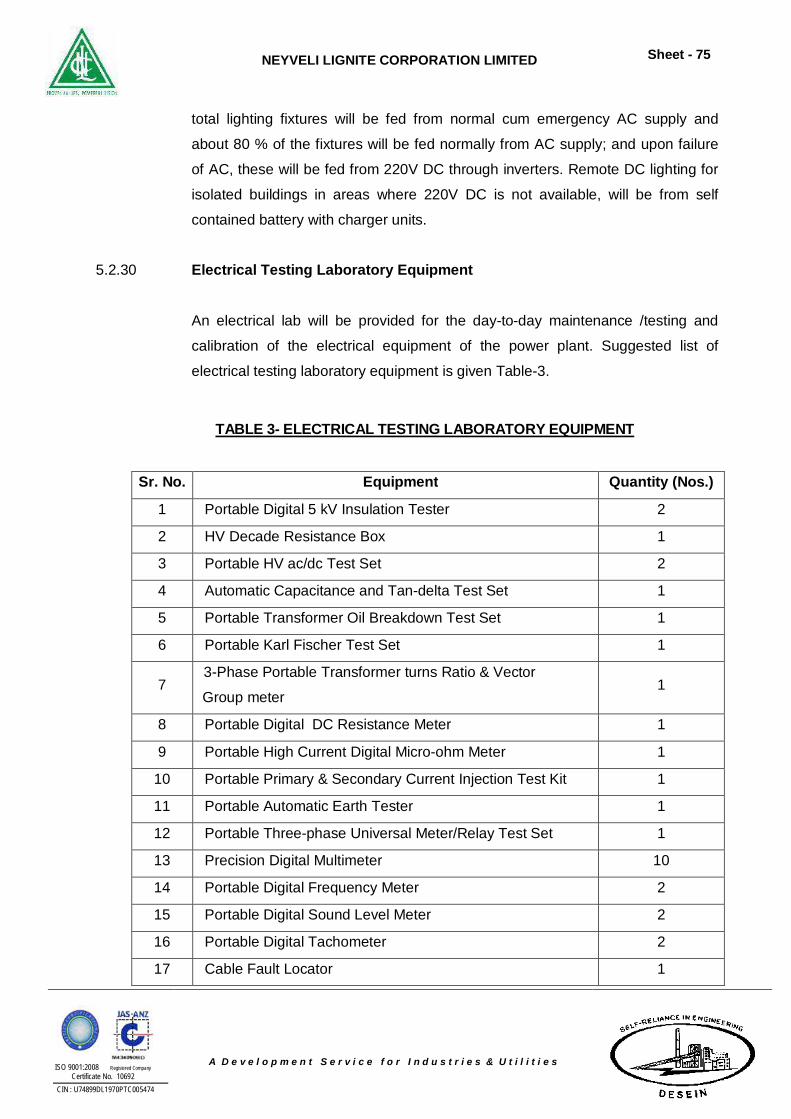
NEYVELI LIGNITE CORPORATION LIMITED
Sheet - 75
ISO 9001:2008 Registered Company Certificate No. 10692
CIN : U74899DL1970PTC005474
A D e v e l o p m e n t S e r v i c e f o r I n d u s t r i e s & U t i l i t i e s
total lighting fixtures will be fed from normal cum emergency AC supply and
about 80 % of the fixtures will be fed normally from AC supply; and upon failure
of AC, these will be fed from 220V DC through inverters. Remote DC lighting for
isolated buildings in areas where 220V DC is not available, will be from self
contained battery with charger units.
5.2.30 Electrical Testing Laboratory Equipment
An electrical lab will be provided for the day-to-day maintenance /testing and
calibration of the electrical equipment of the power plant. Suggested list of
electrical testing laboratory equipment is given Table-3.
TABLE 3- ELECTRICAL TESTING LABORATORY EQUIPMENT
Sr. No. Equipment Quantity (Nos.)
1 Portable Digital 5 kV Insulation Tester 2
2 HV Decade Resistance Box 1
3 Portable HV ac/dc Test Set 2
4 Automatic Capacitance and Tan-delta Test Set 1
5 Portable Transformer Oil Breakdown Test Set 1
6 Portable Karl Fischer Test Set 1
7 3-Phase Portable Transformer turns Ratio & Vector
Group meter 1
8 Portable Digital DC Resistance Meter 1
9 Portable High Current Digital Micro-ohm Meter 1
10 Portable Primary & Secondary Current Injection Test Kit 1
11 Portable Automatic Earth Tester 1
12 Portable Three-phase Universal Meter/Relay Test Set 1
13 Precision Digital Multimeter 10
14 Portable Digital Frequency Meter 2
15 Portable Digital Sound Level Meter 2
16 Portable Digital Tachometer 2
17 Cable Fault Locator 1
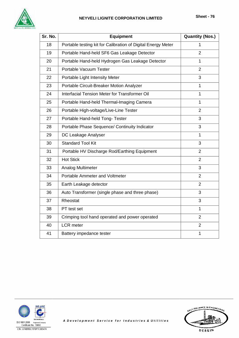
NEYVELI LIGNITE CORPORATION LIMITED
Sheet - 76
ISO 9001:2008 Registered Company Certificate No. 10692
CIN : U74899DL1970PTC005474
A D e v e l o p m e n t S e r v i c e f o r I n d u s t r i e s & U t i l i t i e s
Sr. No. Equipment Quantity (Nos.)
18 Portable testing kit for Calibration of Digital Energy Meter 1
19 Portable Hand-held SF6 Gas Leakage Detector 2
20 Portable Hand-held Hydrogen Gas Leakage Detector 1
21 Portable Vacuum Tester 2
22 Portable Light Intensity Meter 3
23 Portable Circuit-Breaker Motion Analyzer 1
24 Interfacial Tension Meter for Transformer Oil 1
25 Portable Hand-held Thermal-Imaging Camera 1
26 Portable High-voltage/Live-Line Tester 2
27 Portable Hand-held Tong- Tester 3
28 Portable Phase Sequence/ Continuity Indicator 3
29 DC Leakage Analyser 1
30 Standard Tool Kit 3
31 Portable HV Discharge Rod/Earthing Equipment 2
32 Hot Stick 2
33 Analog Multimeter 3
34 Portable Ammeter and Voltmeter 2
35 Earth Leakage detector 2
36 Auto Transformer (single phase and three phase) 3
37 Rheostat 3
38 PT test set 1
39 Crimping tool hand operated and power operated 2
40 LCR meter 2
41 Battery impedance tester 1
NEYVELI LIGNITE CORPORATION LIMITED
Sheet - 77
ISO 9001:2008 Registered Company Certificate No. 10692
CIN : U74899DL1970PTC005474
A D e v e l o p m e n t S e r v i c e f o r I n d u s t r i e s & U t i l i t i e s
5.3 CONTROL AND INSTRUMENTATION SYSTEM
5.3.1 Design Philosophy
The Control and Instrumentation shall be through state of art microprocessor
based Distributed Digital Control, Monitoring and Information System (DDCMIS)
for the entire main plant covering the total functional requirements of modulating
control, sequence control, interlocks & protection, monitoring, alarm, data
logging, fault analysis, performance calculation & optimization, maintenance
scheduling & machine monitoring & analysis etc.
The design of the control system and related equipment shall adhere to the
principle of “fail safe” operation at all system levels (i.e.) the loss of signal, loss of
power or failure of any component should not cause a hazardous condition; and
at the same time prevent occurrence of false trips and provide reliable and
efficient operation of the plant under dynamic conditions and attainment of
maximum station availability.
The complete controls of Boiler, Turbine, Regenerative cycle and few Balance of
plant (BOP) packages are controlled from DDCMIS. Whereas other BOP
packages, which are proprietary in nature, are controlled from separate DCS /
PLC systems. The DDCMIS and DCS shall be of same family.
There shall be one Central control Room (CCR) common for both the units.
5.3.2 Boiler Integral Controls
The Boiler Integral Controls such as Boiler Protection System (BPS / MFT) shall
be implemented in Triple Modular Redundant (TMR) based TUV certified or 2
out of 3 based modules and Furnace Supervisory Safe Guard System (FSSS/
BMS) shall be dual redundant.
NEYVELI LIGNITE CORPORATION LIMITED
Sheet - 78
ISO 9001:2008 Registered Company Certificate No. 10692
CIN : U74899DL1970PTC005474
A D e v e l o p m e n t S e r v i c e f o r I n d u s t r i e s & U t i l i t i e s
a. Furnace Supervisory Safe Guard System (FSSS/ BMS)
The FSSS shall be provided with automatic self-monitoring facility. All
modules to be used in this system shall be of fail safe design. The FSSS
shall meet all applicable relevant safety requirements including those
stipulated in latest editions of VDE 0116, Section 8.7, VDE 0160, NFPA
8502/ 8503 etc. Bidder shall furnish compliance for already implemented
MFT similar to that proposed for this project to VDE 0116, Section 8.7,
VDE 0160 safety standards from recognized / authorized third party
certifying agencies.
b. Secondary Air Damper Control (SADC) System
SADC system shall be provided to achieve the following functions:
i. Control of fuel air flow.
ii. Control of auxiliary air flow at the oil elevations.
iii. Control of wind box/furnace differential pressure.
iv. Limit NOX content in the flue gas by modulating overfire dampers,
if provided.
5.3.3 SG Related Control & Instrumentation System / Equipment
SG Related Control & Instrumentation System / Equipment such as Flame
Monitoring System, Electromatic Relief (Safety) Valves, Furnace Temperature
Probe, Furnace and Flame Viewing System, Acoustic Pyrometer shall be
envisaged.
5.3.4 Turbine Integral Controls
The Turbine Integral Controls such as, Turbine Protection System (TPS), shall
be envisaged in Triple Modular Redundant (TMR) based TUV certified or 2 out
of 3 based, SIL3 fail safe design cards. ATT, ATRS, TSE, HPBP, LPBP, TDBFP
A & B – EHTC / DEH, TPS & TSI, Electro Hydraulic Turbine Control – Governing
NEYVELI LIGNITE CORPORATION LIMITED
Sheet - 79
ISO 9001:2008 Registered Company Certificate No. 10692
CIN : U74899DL1970PTC005474
A D e v e l o p m e n t S e r v i c e f o r I n d u s t r i e s & U t i l i t i e s
system (EHTC / DEH), Main steam turbine EHTC, etc. and other TG integral
controls shall be designed as per dual redundant philosophy.
a. Turbine Protection System (TPS)
The Turbine Protection system shall meet all applicable relevant safety
requirements including those stipulated in latest editions of VDE 0116,
Section 8.7, VDE 0160 etc. The system design shall be such that safety
function of the total system must not be jeopardized on occurrence of
fault. Turbine Protection system initiates turbine trip in case of abnormal
operating conditions for Turbine set and its auxiliary system. All modules
to be used in this system shall be of failsafe design. Turbine Protection
System shall ensure protections such as Bearing Temperature Protection,
Bearing Casing Vibration protection, Condenser Pressure Protection, LP
Exhaust Temperature Protection, Over Speed Protection, Steam Turbine
Protections (Control Fluid Supply, EPBs operated, Boiler Protection
tripped, etc.), etc.
b. Turbine Control System (TCS) Function
The Turbine Control System shall consist of Turbine Governing System,
Turbine Stress Control System HP/LP Bypass system & Automatic
Turbine testing (ATT) system, Automatic Turbine Run-up System (ATRS).
Turbine control system shall be interfaced through OPC with DDCMIS in
addition to Hardwired signals.
c. Turbine Supervisory Instrumentation (TSI) System
The Turbine supervisory Instrumentation system is provided for vibration
measurements of Turbine Generator such as Shaft eccentricity detection,
Differential expansion of rotor and cylinder for HPT, IPT and LPT, Overall
expansion of HPT and IPT, Absolute bearing vibration measurement of
each bearing in both X & Y directions (for turbine and generator bearings),
Axial shift of the rotor, Absolute & relative shaft vibration measurement, of
each bearing in both X & Y direction(for Turbine and Generator bearing),
NEYVELI LIGNITE CORPORATION LIMITED
Sheet - 80
ISO 9001:2008 Registered Company Certificate No. 10692
CIN : U74899DL1970PTC005474
A D e v e l o p m e n t S e r v i c e f o r I n d u s t r i e s & U t i l i t i e s
Turbine speed, Keyphasor, Stator winding vibration measurement in radial
and tangential directions, Emergency stop and Control valve position, etc.
The Turbine Supervisory Instrumentation monitoring system shall meet
the requirement of API-670-1994 (Latest edition) and BS: 4675, Part-2.
The system shall be provided with suitable hardware for necessary signal
processing. The system should suitably Hardwired and soft interfaced with
DDCMIS system.
5.3.5 Station C&I Controls
Station C&I Controls shall include operation, monitoring, sequential interlocks,
Analog Controls & Binary Controls of Boiler and Turbine auxiliary systems such
as CEPs, CPU, Vacuum Pumps, MDBFP, TDBFP, Feed Control station,
Deaerator, HP & LP Heaters, ID fans, FD fans, PA fans, Air Pre Heaters, HP/LP
dosing system, Hotwell make-up pumps, Generator Auxiliaries such as TG Stator
Coil Cooling water, TG H2, CO2 Gas system, TG Seal Oil System, Generator
Monitoring and Auxiliary system, Electrical systems, Common BOP Packages
such as Self-cleaning strainer, COLTCS, CW & ACW Systems, ECW system,
cooling towers, etc.
DDCMIS shall also be suitable to interface BOP DCS and other microprocessor
based control systems through OPC / MODBUS protocols.
5.3.6 BOP Offsite Packages Control System (DCS, PLC, etc.)
The Control for balance of plant (off-site) packages shall be through DCS
covering the total functional requirements of modulating control, sequence
control, interlocks & protection, monitoring, alarm, data logging, etc.
5.3.7 Large Video Screens
Total Three. (3) no. 70 inches full HD Large Video Screens (LVS) shall be
provided for each unit DDCMIS and two (2) nos. LVS for common DDCMIS along
with workstation and graphic processor to dynamically display plant data/ mimic/
NEYVELI LIGNITE CORPORATION LIMITED
Sheet - 81
ISO 9001:2008 Registered Company Certificate No. 10692
CIN : U74899DL1970PTC005474
A D e v e l o p m e n t S e r v i c e f o r I n d u s t r i e s & U t i l i t i e s
alarms/ and any other process information. Common system LVS shall have
additional features to work in association with multiple numbers of plant cameras.
5.3.8 Uninterruptible Power Supply (UPS) Systems
Separate “2x100% parallel redundant UPS with 50% load sharing with static
bypass through static switch to Static controlled voltage stabilizer regulated
supply” including static inverters, static switches, manual bypass switch,
chargers, A.C. Power distribution panels and 2 x 100% Battery banks with all
required isolating and protecting devices and all other equipment and
accessories required for completeness of this system. There shall be no common
component like in phase transformer (IPT), common power supply to any
redundant component and common point of failure in the UPS.
The type of batteries shall be 2 V Plante type Batteries for Main Plant, CHP,
AHP, DM Plant, etc. Whereas for other systems / packages, 2 V, SMF lead –
Acid / Ni-cd batteries shall be provided.
Applicable codes and standards for UPS System include ANSI, NEMA, TEEE,
NEC and IS. The UPS shall cater power supply to all 230 VAC operated
instruments, Analyzers, Solenoid Valves, Annunciation System, DDCMIS / DCS
peripherals such as Work stations, Printers, Network switches, LVS, etc. within
the control room and/or in the field.(Outside the main control room)and comes
under the scope of SG & STG packages as well as BOP packages. All UPS
systems for main plant as well as for BOP off-site packages shall preferably be of
same make.
5.3.9 Field Instruments
All required field instrument including erection hardware like Transmitters,
switches, RTD, Thermocouple, Gauges, Flow Element, control valves, etc. for
proper control, operation & monitoring of instrumentation and control, system
shall be provided. All transmitters shall be HART protocol based as far as
possible.
NEYVELI LIGNITE CORPORATION LIMITED
Sheet - 82
ISO 9001:2008 Registered Company Certificate No. 10692
CIN : U74899DL1970PTC005474
A D e v e l o p m e n t S e r v i c e f o r I n d u s t r i e s & U t i l i t i e s
5.3.10 HART Management System
A dedicated standalone PC based HART Management System (HMS) will be
provided for centralized configuration, maintenance, diagnostic and record
keeping of all electronic smart transmitters. The type of transmitters covered is
Pressure, Differential Pressure, DP type Flow & Level Transmitters, Flow Meters,
Level Transmitters and Smart Positioner.
5.3.11 Steam and Water Analysis System (SWAS)
Separate Steam and Water Analysis System shall be envisaged for continuous
monitoring and control of water and steam purity in the plant cycle of each unit.
The system shall be designed in accordance with the recommendations in ASME
PTC 19.11 (2008), Water and Steam in Power Cycle, ASTM standards - 31 water
and ASTM D1066-69 standard method of sampling steam.
5.3.12 Continuous Environment Monitoring System (CEMS)
Separate Continuous Environment Monitoring System shall be envisaged for
each Unit as per Emission latest Regulation of CPCB/State PCB. CEMS shall
comprises of Flue Gas Oxygen analyzer for control and monitoring, Carbon Mono
Oxide, Sox / NOx, Dust & Opacity analyzer, Mercury analyser for Boiler Emission
monitoring system. The CEMS shall be interfaced with state PCB suitably.
5.3.13 Instrumentation Cables
Instrument (pair / core) cables (annealed, tinned copper conductor, 650 V grade,
0.5 sq mm (signal cable) / 1.5 sq mm (control cable). FRLS type, PVC insulated,
Stranded Drain wire, Aluminum Mylar type shielding armoured, ST1 type Inner
Sheathing, ST-2 type outer Sheathing for analog and digital signals for
connecting field instruments, switches, transmitters to respective junction box and
compensating cables used to interconnect thermocouples to control and
monitoring systems (KX, 1.5sqmm, FRLS type, PVC insulated, armoured)
complete with all accessories are envisaged.
NEYVELI LIGNITE CORPORATION LIMITED
Sheet - 83
ISO 9001:2008 Registered Company Certificate No. 10692
CIN : U74899DL1970PTC005474
A D e v e l o p m e n t S e r v i c e f o r I n d u s t r i e s & U t i l i t i e s
5.3.14 Master Clock System
The Master clock system shall be provided based on Global Positioning system
(GPS). Redundant Master clock shall have separate signal conditioner facilities to
transmit clock pulses of specific formats, (such as IRIG-B, pulse, NTP/SNTP etc.)
for time synchronizing other equipment in the power plant such as, DDCMIS
system, PLCs, SOE & for all microprocessor based system like TSI, VMS, HMS,
Flame monitoring & detector system, etc. All the PLC & Microprocessor based
system in entire plant shall be time synchronized from Master Clock System.
Master Clock System shall be common for all the system in complete plant.
5.3.15 Vibration Monitoring and Analysis System
One no. Microprocessor based standalone online vibration / machinery
monitoring and analysis system for each unit shall be used for condition
monitoring, analysis & diagnostic of STG and HT drives/motors with fans /
pumps, air compressor, and any other HT drives envisaged for subject plant.
5.3.16 C&I Lab Instruments
One (1) no. Computer aided Pneumatic and Electronic C&I maintenance
calibration instruments/equipment shall be provided for calibration of Pressure,
temperature and other electrical field instruments common for both units. Table
mounted calibration instruments having highest accuracies to support
testing/calibration of field instruments whereas the portable calibration
instruments shall be used for site applications to perform testing / calibration at
site. Automatic calibration and system documentation for generating calibration
certificates, keeping calibration / maintenance records for which one workstation
shall be provided.
5.3.17 Acoustic Pyrometer
5.3.18 Plant Security and Surveillance System
The Plant security and surveillance system shall be provided taking into account
the potential security risk to the plant. The system comprises of perimeter intruder
NEYVELI LIGNITE CORPORATION LIMITED
Sheet - 84
ISO 9001:2008 Registered Company Certificate No. 10692
CIN : U74899DL1970PTC005474
A D e v e l o p m e n t S e r v i c e f o r I n d u s t r i e s & U t i l i t i e s
detection system and plant monitoring system. All CCTV cameras shall be IP
based, with weather proof enclosures for outdoor applications, fire/explosion
proof enclosures for FOPH area and H2 generation plant (as per NEC code).
System shall be provided as follows:
i. Total perimeter - IP based fixed cameras
ii. Inside Plant - IP based PT2 cameras
iii. For transformer and switchyard area - Thermovision cameras
iv. CCTV - connectivity/control-service building
5.3.19 Performance Calculations, Analysis, Diagnostic and Optimization Package (PADO)
PC based online Performance analysis, diagnosis & optimization system (PADO)
for station, which will provided proper guidance to plant operator to enhance
operational efficiency, carry out process and equipment diagnosis to ensure
against performance degradation and facilitate optimal controller tuning.
The performance calculation shall be broadly sub divided into two classes:
Class I : Equipment protection calculations and
Class II : Plant equipment efficiency calculations.
The Diagnostic and Optimization Package shall include Boiler Performance
Optimisation System (BPOS), Soot Blowing Optimization Module, Boiler Stress
analyzer and service life monitoring, Emission Analysis and Monitoring and
Interactive Chemistry control, Regenerative cycle performance optimization,
Water Chemistry Management, Merit order Rating System, etc.
5.3.20 Station LAN, Management Information System (MIS) and Computerised
Maintenance & Inventory Management System (CMIMS)
A plant wide Local Area Network (LAN) encompassing the different plant
buildings shall be provided. The Station LAN shall interconnect all the buildings
together and shall facilitate the smooth transfer of Data from one building to the
other.
NEYVELI LIGNITE CORPORATION LIMITED
Sheet - 85
ISO 9001:2008 Registered Company Certificate No. 10692
CIN : U74899DL1970PTC005474
A D e v e l o p m e n t S e r v i c e f o r I n d u s t r i e s & U t i l i t i e s
An integrated management information system (MIS) shall be provided, which
includes Plant operation information, Plant maintenance related information and
Environmental information.
CMIM system will consist of different application modules specific to the
maintenance tasks normally encountered in Thermal Power Station; system will
have capabilities to document maintenance related functions and will streamline
the entire maintenance activities. Features like generation of work order,
preventive maintenance schedule, inventory control, storing of equipment
information, job planning, purchase modules and report generation will be
available.
5.3.21 Interface with Numerical Relays and Intelligent Controllers
For HT switchgear feeders for ACB control incomers, bus couplers, LT
switchgear feeders etc. Numerical relays shall be provided with IEC 61850
protocol and shall be directly linked to DDCMIS without converters through
redundant communication.
For LT MCC feeders intelligent controllers shall be provided, Ethernet-based
protocol shall be used for linking to DDCMIS.
NEYVELI LIGNITE CORPORATION LIMITED
Sheet - 86
ISO 9001:2008 Registered Company Certificate No. 10692
CIN : U74899DL1970PTC005474
A D e v e l o p m e n t S e r v i c e f o r I n d u s t r i e s & U t i l i t i e s
5.4 CIVIL AND STRUCTURAL ENGINEERING ASPECTS
5.4.1 SITE TOPOGRAPHY AND GRADE LEVEL SITE
a. Seismological Studies
NLC has not carried out any seismological study in the proposed area.
However, this area falls in seismology zone II as per GSI.
b. Geological information like type of geological formation, mineral
deposits, possible mining operations in the region.
The top formation of the project area is mainly comprises of a thin layer of
laterites & lateritic gravels as top soil with thickness range of 4-11 mts
which is grouped under Quaternary formation followed by Cuddalore
series. The Cuddalore series an comprising argillaceous sandstone,
ferruginous sandstone, grits, clays beds, the associated lignite beds and
the water bearing sands of the Neyveli artesian acquifer. Due to frequent facies variation, different lithological units do not exhibit a
regular nature. Irregular hard rock bands – either lateritic boulders or
silicified sandstone.
The sandstones of the Cuddalore series are whitish, pinkish, reddish or
mottled in colour and are chiefly argillaceous and ferruginous. The sands
and sandstones range in size from fine to very coarse grained and are
sub-angular to subround in shape. They also include pebbles of up to
2.5mm in diameter, which are generally rounded. To the north-western
high ground there is a fairly steep slope or escarpment face along which
some of the above sandstones are exposed.
NEYVELI LIGNITE CORPORATION LIMITED
Sheet - 87
ISO 9001:2008 Registered Company Certificate No. 10692
CIN : U74899DL1970PTC005474
A D e v e l o p m e n t S e r v i c e f o r I n d u s t r i e s & U t i l i t i e s
In the proposed TPS-II second expansion area is falling out of lignite
bearing area. The lignite mining (Mines-I * expan) by NLC is about 6kms
away from the project area.
5.4.2 MAJOR BUILDINGS AND STRUCTURES
Station Building
The station building would be a non-basement structure. For proposed plant, the
steam turbine generator and auxiliary equipment would be located in the A-B bay
of the building having span in the range of 30 to 35m and is accommodated in a
length of 10.5 m x 24 bays (Approx.). The total length of the station building
would be in the range of 240 to 260 m which includes one unloading cum
maintenance bay of 10.5 m width towards one end of the station building. The B-
C bay having a span of 12 m would be housing the heaters. The control room
and electrical building of approximate size will be located on the side of the
station building to accommodate switch gear, electronic panels and control
instrumentation equipment.
For Proposed plant, the turbine – generator bay would have three floors – ground
floor at 0.00 M level, mezzanine floor at 8.50 M level and operating floor at 17.00
M level. Localised O&M platforms at required levels would be provided. The
deaerator would be located at higher elevation in the B-C bay (heater bay).
Road and rail access would be provided to the unloading and maintenance bay
for unloading TG components and auxiliary equipment.
For the Proposed Plant, the superstructure would be of structural steel framing
with RCC floor slabs. Brick work side cladding up to 3.0 m above operating floor
level and metal sheet cladding above this level has been considered for ‘A’ Row
Gable end 8m to 10m height whereas for B&C rows full height brick wall will be
provided upto the deaerator floor. The roof of the TG bay would be permanent
metal decking with in-situ concrete and screed on top and supported on steel
trusses. Building would have crane girder at a suitable elevation to support the
E.O.T cranes. Intermediate floors are supported with internal columns around
TG foundation. All floors of turbine hall (except operating floor and control
NEYVELI LIGNITE CORPORATION LIMITED
Sheet - 88
ISO 9001:2008 Registered Company Certificate No. 10692
CIN : U74899DL1970PTC005474
A D e v e l o p m e n t S e r v i c e f o r I n d u s t r i e s & U t i l i t i e s
rooms) would be provided with non-metallic hardener topping. Preferably
Operating floor would be provided with suitable tiles. Control room floor shall
have 3 mm thick PVC anti-skid floor finish.
For proposed plant, the turbine-generator pedestal would be of reinforced
concrete frame structure and would be isolated from the building foundations and
super-structure. Steam turbine generator would be supported on vibration
isolation system. The vibration isolation system would consist of helical spring
units and viscous dampers supporting the RCC inertia block, which supports the
machine. Considering soil condition, piling will be provided below TG
Foundation.
5.4.3 Steam-Generator Area and Mill Bay
For the Proposed plant, the mill bay would be of structural steel-framed
construction, supporting the steel bunkers. The bay would have floors for the
feeders and for the trippers. The mill bay would be located on both sides of the
furnace and will be connected by steel framing between the ESP & steam
generator in order to isolate dust and vibration that would affect the control room
housed in the station building. Concrete paving would be provided in the steam
generator and ESP area with necessary drains and trenches. Pipes and cable in
this area would, in general, be routed on overhead pipe / cable racks.
5.4.4 Stack
A twin flue reinforced concrete stack of 275 M height of 7.0 m (Approx.) minimum
exit diameter would be provided for 2 x 500 MW steam generator units. This
would meet the requirement of Indian Emission Regulations OF Ministry of
Environment and Forest (MOEF).
5.4.5 Condenser Cooling Water Water for condenser cooling system would be drawn from the proposed Mines-III
circulated in the NDCT cooling tower. Five (4W+1S) nos. of Cooling Water
Pumps would be installed in the cooling water pump house.
NEYVELI LIGNITE CORPORATION LIMITED
Sheet - 89
ISO 9001:2008 Registered Company Certificate No. 10692
CIN : U74899DL1970PTC005474
A D e v e l o p m e n t S e r v i c e f o r I n d u s t r i e s & U t i l i t i e s
5.4.6 Ash Pond
For proposed power plant of 2 x 500 MW, fly ash, (about 70% of the total ash
generated) will be disposed off in dry condition and bottom ash (about 20% of the
total ash generated) will be disposed into the existing ash pond.
5.4.7 Miscellaneous Buildings
Miscellaneous buildings will be RCC / Steel construction with adequate floor area
and size.
5.4.8 Hydraulic, Geotechnical and Soil Investigations
A detailed geo-tech investigation needs to be carried out in the proposed power
plant site to ascertain the soil profile and decide on the safe bearing capacity /
pile capacity to be considered for the foundation design of main columns of major
buildings / structures, main equipment.
Construction material such as sand, coarse aggregates good quality bricks and
size stone metal required for the construction of the proposed power plant would
be procured from nearby sources. Use of environmentally friendly fly ash bricks
would be explored for use in the proposed power plant. The construction power
would be catered by provision of a temporary power connection from the nearest
LT power line.
5.4.9 Foundations
The foundations for the buildings and structures of the proposed power plant, has
been considered as Pile foundations.
5.4.10 Roads and Fences / Compound Wall
The roads would initially be of water-bound macadam type with shoulders on
either side of carriage width. After major construction activities are completed,
NEYVELI LIGNITE CORPORATION LIMITED
Sheet - 90
ISO 9001:2008 Registered Company Certificate No. 10692
CIN : U74899DL1970PTC005474
A D e v e l o p m e n t S e r v i c e f o r I n d u s t r i e s & U t i l i t i e s
these would be surfaced with Concrete. The width of the double lane road would
be 7.5 meter excluding shoulders and single lane would be 4 m. Extra width
would be provided on either side, for road side tree plantation, for all internal road
in the plant site. It is also considered to provide RCC roads around boilers and
transformers. The compound wall would be of stone masonry construction with
barbed wire fixed to MS angles on the top.
5.4.11 Rain Water Harvesting (RWH)
RWH structures will be provided to harvest the rain water around the power plant
area. The collected rain water shall be utilized for power plant uses to optimize
the raw water requirement. The excess rain water may be discharged to the
nearest surface water body through dedicated storm water drain. The surface
water run-off from the main plant area would be led to a sump for settling and the
over flow would be collected in the common water basin for further uses in the
power plant to optimize the raw water requirement of the plant.
5.4.12 Design Basis
Dead and live loads would be considered as per relevant IS codes and standard
engineering practices. The basic wind speed shall be considered for design of
buildings / structures as per IS:875:Part III. The power plant is located in Seismic
zone III as per IS:1893 and hence seismic forces would be considered
accordingly for the structures and buildings. All designs shall be carried out in SI
units and shall be as per relevant IS codes.
5.4.13 Sewage Disposal Sewage from the plant would be conveyed through closed drains upto Sewage
treatment plant as per the Pollution Control Board Norms. The treated water is
collected and used for the greenbelt area development.
NEYVELI LIGNITE CORPORATION LIMITED
Sheet - 91
ISO 9001:2008 Registered Company Certificate No. 10692
CIN : U74899DL1970PTC005474
A D e v e l o p m e n t S e r v i c e f o r I n d u s t r i e s & U t i l i t i e s
5.4.14 Landscaping
The various services / utility areas within the plant would be suitably graded to
different elevations. Natural features of the plant site would be retained as far as
possible to integrate with the buildings to form a harmonious / pleasant
environment. Areas in from of various buildings and the entrance of power plant
would be landscaped with ground cover, plants, trees based on factors like
climate, adaptability, etc. The green belt would consist of native perennial green
and fast growing trees. Trees would also be planted around the lignite stock pile
area and ash disposal area to minimize the dust pollution. Green belt should
have suitable trees to act as a shelter-belt during the cyclone periods.
NEYVELI LIGNITE CORPORATION LIMITED
Sheet - 92
ISO 9001:2008 Registered Company Certificate No. 10692
CIN : U74899DL1970PTC005474
A D e v e l o p m e n t S e r v i c e f o r I n d u s t r i e s & U t i l i t i e s
6.0 PLOT PLAN AND GENERAL ARRANGEMENT
6.1 Plot Plan
2 x 500 MW Plot Plan is shown in attached Annexure - 6.1.
The layout of the project shows the location of main plant equipment with its
auxiliaries, coal storage area, switchyard, raw water storage reservoir. The plant
layout has been developed keeping in view the following:-
i. Location within the designated area best suited from the point of view of
available land offering least site grading costs.
ii. Wind rose directions.
iii. Proximity to road network and rail link.
iv. Accessibility to water source and intake system.
v. Accessibility to power evacuation corridor.
The main plant equipment and auxiliary system are located based on the unit
system design concept except for common facilities such as 400/230 KV
switchyard, water system, coal and fuel oil unloading and handling facilities, ash
disposal system.
The layout provides for:-
i. Dedicated Raw Water Reservoir.
ii. Storage space for coal and secondary fuel.
iii. Space for future FGD Plant.
iv. Green belt all around the plant.
v. Administrative building.
vi. Adequate space for built-up and open area for construction offices,
stores, fabrication yard, pre-assembly yard etc.
vii. Ash dump area.
NEYVELI LIGNITE CORPORATION LIMITED
Sheet - 93
ISO 9001:2008 Registered Company Certificate No. 10692
CIN : U74899DL1970PTC005474
A D e v e l o p m e n t S e r v i c e f o r I n d u s t r i e s & U t i l i t i e s
6.2 General Plant Layout
400/230 KV switchyard is located on West of the plant building beyond
transformer yard.
Raw water reservoir is on the south of the plant. Natural draft cooling tower and
water facilities are located suitably on the East & South respectively of the plant.
The coal handling plant and North-East and ash dump on South side of the
power block.
The auxiliary and ancillary building includes:
i. Fire station
ii. Work shop
iii. Hydrogen generation plant
iv. Canteen
v. Compressor House
vi. Emergency diesel generators station.
vii Storage sheds.
6.2.1 Layout of Steam Generator and Auxiliaries
The layout is indicative and will be based on the design of the Developer.
The flue gas ducts from the air heater pass below feeder floor for connection to
ESP; and then will be connected to a 275 M high RCC stack, flue
connected through two (2) ID fans for each unit. ESP control room will be
provided separately for each unit.
Ash pump house with slurry sump will be located near ESP.
6.2.2 Layout of Machine Room Building with Annex
The machine room building will comprise of turbine hall followed by for electrical
and control rooms. A clear passage will be kept between C-row column line and
boiler first columns to facilitate critical pipe work routing into the machine room;
NEYVELI LIGNITE CORPORATION LIMITED
Sheet - 94
ISO 9001:2008 Registered Company Certificate No. 10692
CIN : U74899DL1970PTC005474
A D e v e l o p m e n t S e r v i c e f o r I n d u s t r i e s & U t i l i t i e s
and to locate other auxiliary equipment.
415 V & 3.3 KV Switchgear will be located mostly on floors in B/C bay in
between the machines, boiler auxiliaries MCC; boiler valves MCC; Soot-blower
MCC.240 Volt station battery units and its chargers-room along with UPS
batteries will be also located in B/C bays. Control equipment room, DCS room,
24 V battery and its charger-room for the units will be located between B/C bays.
Regenerative feed water heaters will be located in the machine hall between
A/B bays (LP heaters below operating floor while HP heaters will be located at
operating floor, in case horizontal heaters are selected) close to B-row.
The main equipment erection hatch will be located at the end of AB bay suitable
for rail entry under the machine room EOT cranes and its lifting beam.
Two (2) nos. natural draft cooling tower for cooling the circulating water will
selected, considering the wind directions such that it does not affect the 400/
230 KV switchyard.
Transformer yard will have RCC rail track up to unloading bay of TG hall for
shifting of generator transformer during erection & maintenance.
NEYVELI LIGNITE CORPORATION LIMITED
Sheet - 95
ISO 9001:2008 Registered Company Certificate No. 10692
CIN : U74899DL1970PTC005474
A D e v e l o p m e n t S e r v i c e f o r I n d u s t r i e s & U t i l i t i e s
7.0 ENVIRONMENTAL CONSIDERATIONS
The Environment (Protection) Act of the Ministry of the Environment and Forests
(MoEF) is an umbrella act that covers the EIA notification. The proposed thermal
power project attracts Environmental Impact Assessment (EIA) requirement of
the notification and thus requires Environmental Clearance. The MoEF has re-
engineered the process of Environmental Clearance vide its Notification dated
14 th September, 2006 suppressing the EIA Notification of 27th January, 1994
and its various amendments.
The new procedure has defined four stages of environmental clearance process.
These stages in sequential order are as follows:-
- Stage (1) screening
- Stage (2) scoping
- Stage (3) public consultation
- Stage (4) appraisal
The above notification requires industries to carry out EIA study in accordance
with MoEF guidelines after scoping and determination of the Terms of Reference
(ToR) on likely impacts on the existing environment. Based on studies carried
out in respect of identified activities including atmospheric emission and effluent
discharge, predictions are made on the anticipated effects. To ensure that
expected levels fall within prescribed limits, delineation of mitigation including
environmental management plan is necessary for compliance. The notification
also provides public consultation to mitigate public concerns for the proper
compensation and rehabilitation of project affected persons.
Lignite fired thermal power station contribute to environmental pollution as
follows:
a) Atmospheric pollution through particulate and gaseous emissions.
b) Thermal pollution of the surroundings.
c) Pollution due to discharge of liquid and solid wastes.
d) Noise pollution.
NEYVELI LIGNITE CORPORATION LIMITED
Sheet - 96
ISO 9001:2008 Registered Company Certificate No. 10692
CIN : U74899DL1970PTC005474
A D e v e l o p m e n t S e r v i c e f o r I n d u s t r i e s & U t i l i t i e s
7.1 Air Pollution Control System
Electrostatic precipitators (ESP) will be installed to control the emission of ash
particles. The precipitators will be designed to limit the particulate emission to
less than 30 mg/Nm3. As per the MOEF amended notification (5.0.3305 (E)
dated 7th December, 2015), all new plants to be installed after 10th Jan. 2015
shall have to meet the updated Standard Environmental (Protection) Act, 1986
with the following emission limits:
PM - 30 mg/Nm3
SO2 - 100 mg/Nm3
NOx - 100 mg/Nm3
Hg - 0.03 mg/Nm3
One (1) no. stack of 220 m height will be provided based on existing CPCB /
MOEF norms for wider dispersion. For the control of fugitive dust emission within
and around the fuel handling plant, fuel dust extraction and suppression systems
will be provided.
7.2 Water Pollution Control System
Effluent management scheme will be implemented with the objective of
optimization of various water systems so as to reduce intake water requirement
which will result in lesser waste water discharge. Adequate treatment facilities
will be provided to all the waste streams emanating from the power plant to
control water pollution.
7.3 Noise Pollution
Ambient noise inside and outside the plant area will conform to the prescribed
noise levels for various land use categories as per National Standards for
Ambient Noise. This will be ensured through proper designing of the equipment
with adequate acoustics permitting the ambient noise levels without exceeding
the specified criteria from the source.
NEYVELI LIGNITE CORPORATION LIMITED
Sheet - 97
ISO 9001:2008 Registered Company Certificate No. 10692
CIN : U74899DL1970PTC005474
A D e v e l o p m e n t S e r v i c e f o r I n d u s t r i e s & U t i l i t i e s
Green belt of adequate width will be provided around plant boundary and
strategic locations.
7.4 Solid Waste Management
The ash management scheme for the ash generated from power plant will
involve dry collection of fly ash, supply of ash to entrepreneurs for utilization,
promoting ash utilization and disposal of unused ash.
7.5 Action Plan
Ministry of Environment and Forests (MoEF) Notification dated 3rd
November, 2009) stipulate that “new coal and, or lignite based thermal
power station and, or expansion units commissioned after this notification to
achieve the target of fly ash utilization as per Table-I given below:
TABLE-I
Sl. No. Fly ash utilization level Target date
1. At least 50% of fly ash generation
One year from the date of commissioning
2. At least 70% of fly ash generation
Two years from the date of commissioning
3. 90% of fly ash generation
Three years from the date of commissioning
4. 100% of fly ash generation
Four year from the date of commissioning
The unutilized fly ash in relation to the target during a year, if any, shall be
utilized within next two years in addition to the targets stipulated for these years
and the balance unutilized fly target) shall be utilized progressively over next five
years in addition to 100% utilization of current generation of fly ash.
Considering the above guidelines & stipulations regarding utilization of fly ash,
the project proponent will take necessary steps.
Terms of Reference (TOR) for conducting REIA studies will be processed by the
Environmental Impact Assessment Authority, MOEF and the report will be
prepared based on the TOR and will be submitted for MOEF clearance.
NEYVELI LIGNITE CORPORATION LIMITED
Sheet - 98
ISO 9001:2008 Registered Company Certificate No. 10692
CIN : U74899DL1970PTC005474
A D e v e l o p m e n t S e r v i c e f o r I n d u s t r i e s & U t i l i t i e s
8.0 EXECUTION AND MANAGEMENT
The Project is proposed to be executed as in-house project and as such
Execution and Management of the project as well as the O&M will be as per the
prevailing methods and practice of the Owner.
8.1 Completion Schedule
The project will be scheduled for the two units to go into commercial
operation in 50 months after the zero date. Zero date is considered as the date
on which the BTG package / turnkey EPC contract is awarded.
NEYVELI LIGNITE CORPORATION LIMITED
Sheet - 99
ISO 9001:2008 Registered Company Certificate No. 10692
CIN : U74899DL1970PTC005474
A D e v e l o p m e n t S e r v i c e f o r I n d u s t r i e s & U t i l i t i e s
9.0 PROJECT COST
The tentative project & cost per MW has been worked out and the figures are as
under:
Cost of Project including IDC ` 7000 Crores Cost per MW ` 7.00 Crores
The above estimates are for the purpose of Feasibility Report without any
detailed estimation of bill of quantities. However, the detailed cost estimates and
financial analysis will be carried out during Detailed Project Report stage, based
on the specific available data.
NEYVELI LIGNITE CORPORATION LIMITED
Sheet - 100
ISO 9001:2008 Registered Company Certificate No. 10692
CIN : U74899DL1970PTC005474
A D e v e l o p m e n t S e r v i c e f o r I n d u s t r i e s & U t i l i t i e s
10.0 CONCLUSION
On analysis of all aspect involved for the development of the project, it is
concluded that:
“It is technically feasible to establish 2 x 500 MW units based on Sub-critical
Technology at the site identified for the project considering the availability of
infrastructural facilities subject to obtaining the statutory & non statutory
clearance of the concerned authority & tying up of inputs as outlined at chapter
– 2 of the report.”
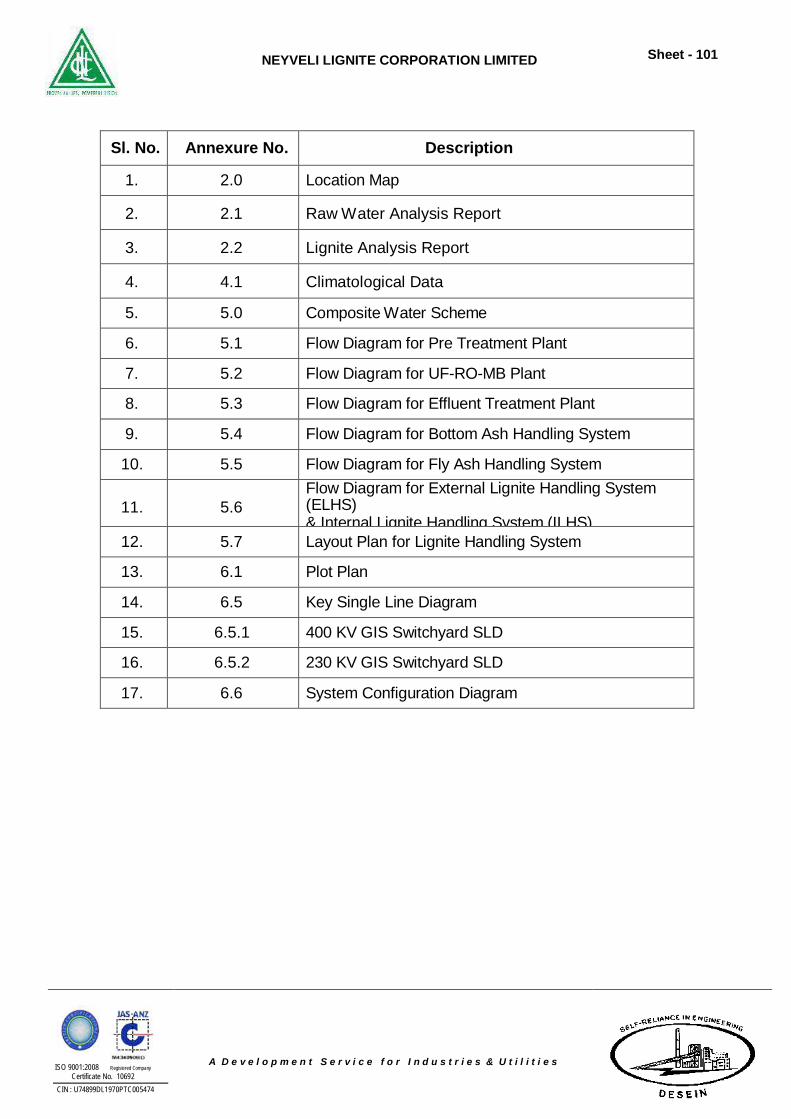
NEYVELI LIGNITE CORPORATION LIMITED
Sheet - 101
ISO 9001:2008 Registered Company Certificate No. 10692
CIN : U74899DL1970PTC005474
A D e v e l o p m e n t S e r v i c e f o r I n d u s t r i e s & U t i l i t i e s
Sl. No. Annexure No. Description
1. 2.0 Location Map
2. 2.1 Raw Water Analysis Report
3. 2.2 Lignite Analysis Report
4. 4.1 Climatological Data
5. 5.0 Composite Water Scheme
6. 5.1 Flow Diagram for Pre Treatment Plant
7. 5.2 Flow Diagram for UF-RO-MB Plant
8. 5.3 Flow Diagram for Effluent Treatment Plant
9. 5.4 Flow Diagram for Bottom Ash Handling System
10. 5.5 Flow Diagram for Fly Ash Handling System
11.
5.6 Flow Diagram for External Lignite Handling System (ELHS) & Internal Lignite Handling System (ILHS)
12. 5.7 Layout Plan for Lignite Handling System
13. 6.1 Plot Plan
14. 6.5 Key Single Line Diagram
15. 6.5.1 400 KV GIS Switchyard SLD
16. 6.5.2 230 KV GIS Switchyard SLD
17. 6.6 System Configuration Diagram
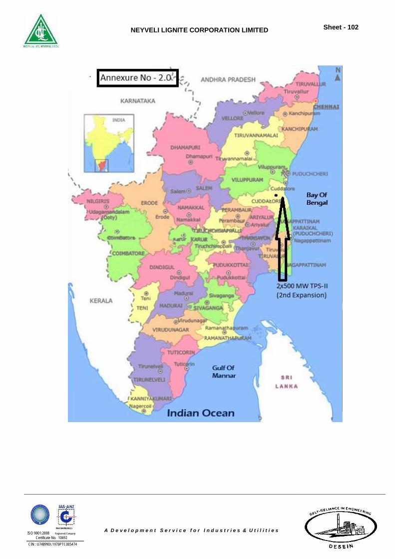
NEYVELI LIGNITE CORPORATION LIMITED
Sheet - 102
ISO 9001:2008 Registered Company Certificate No. 10692
CIN : U74899DL1970PTC005474
A D e v e l o p m e n t S e r v i c e f o r I n d u s t r i e s & U t i l i t i e s
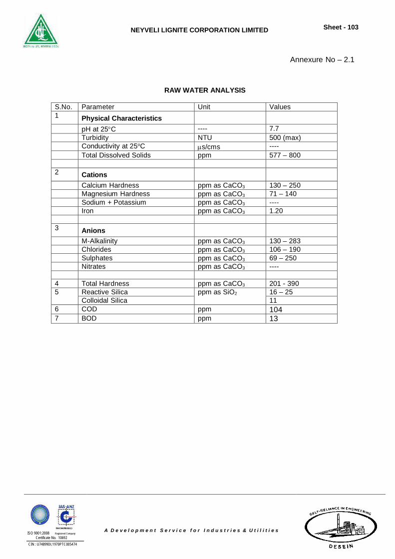
NEYVELI LIGNITE CORPORATION LIMITED
Sheet - 103
ISO 9001:2008 Registered Company Certificate No. 10692
CIN : U74899DL1970PTC005474
A D e v e l o p m e n t S e r v i c e f o r I n d u s t r i e s & U t i l i t i e s
Annexure No – 2.1
RAW WATER ANALYSIS
S.No. Parameter Unit Values 1 Physical Characteristics
pH at 25C ---- 7.7 Turbidity NTU 500 (max) Conductivity at 25oC s/cms ---- Total Dissolved Solids ppm 577 – 800 2 Cations
Calcium Hardness ppm as CaCO3 130 – 250 Magnesium Hardness ppm as CaCO3 71 – 140 Sodium + Potassium ppm as CaCO3 ---- Iron ppm as CaCO3 1.20 3 Anions
M-Alkalinity ppm as CaCO3 130 – 283 Chlorides ppm as CaCO3 106 – 190 Sulphates ppm as CaCO3 69 – 250 Nitrates ppm as CaCO3 ---- 4 Total Hardness ppm as CaCO3 201 - 390 5 Reactive Silica ppm as SiO2 16 – 25
Colloidal Silica 11 6 COD ppm 104 7 BOD ppm 13
NEYVELI LIGNITE CORPORATION LIMITED
Sheet - 104
ISO 9001:2008 Registered Company Certificate No. 10692
CIN : U74899DL1970PTC005474
A D e v e l o p m e n t S e r v i c e f o r I n d u s t r i e s & U t i l i t i e s
ANNEXURE No. – 2.2
M-III BLOCK LIGNITE QUALITY
Quality of Lignite is generally arrived from the analysis of lignite core samples generated
from exploratory boreholes for any new mines. During exploration in the Neyveli Lignite field,
the occurrence of marcasite has been observed within the Lignite seam. The Data of drilling
exploration on the Neyveli Lignite quality of the already opened up Mine-I & II do not show any
essential differences in average value and variation range of relevant quality parameter after a
through statistical evaluation. However the differences in geological quality of the raw lignite
from mine-II have been already recognised macroscopically at the lignite cut faces. Even
though the Marcasite is associated with lignite in the Neyveli field, the concentration of
Marcasite is not reflected much due to increase in thickness of Lignite in Mine-I. The
concentration of Marcasite is reflected much in the trough areas of lignite top and also at the
occurrence of the seam associated with water bearing sands. Similar condition is existing in the
proposed Mine-III area also and hence the Marcasite problem may have to be carefully
considered for mining operation. Marcasite occurs in the form of globular, lenticular, veins and
platty concretion. It is a modification of Ferric Sulphide (FeS2) with dirty metallic greenish /
yellow colour. The hardness of marcasite varies form 5 to 7.5, the specific gravity ranges from 3
to 4.5. Marcasite does not occur as magnetic mineral and it has a compressive strength of 150
to 800 Kg/cm2.
The occurrence of Marcasite posed difficulties during drilling operation by the wear and
tear of the drilling bits, clogging of the bore hole thereby forcing drilling operation to be
suspended temporarily. It poses certain difficulties in the excavation and conveying process
causing damages to vital parts of the mining machineries (Viz bucket wheel teeth) and
damages to the belts. The marcasite content of the lignite causes problem in the power plant
operation that are visible in the form of damages to the crushers and boiler mill as well as by
major slagging in the boiler. There are three forms of sulphur in the Lignite and they are organic
sulphur, sulphate sulphur and sulphide sulphur. Among these, sulphide sulphur which is
associated with marcasite is harmful to Boiler by reacting with iron molecules thus resulting slag
formations in the boilers. The occurrence of marcasite in the lignite results in the formation of
FeO in reducing atmosphere during combustion and this FeO will act as a flux to reduce the
melting characteristics of the ash constituents resulting slag formation.
Separation of Marcasite from lignite is very difficult due to physical characteristics and
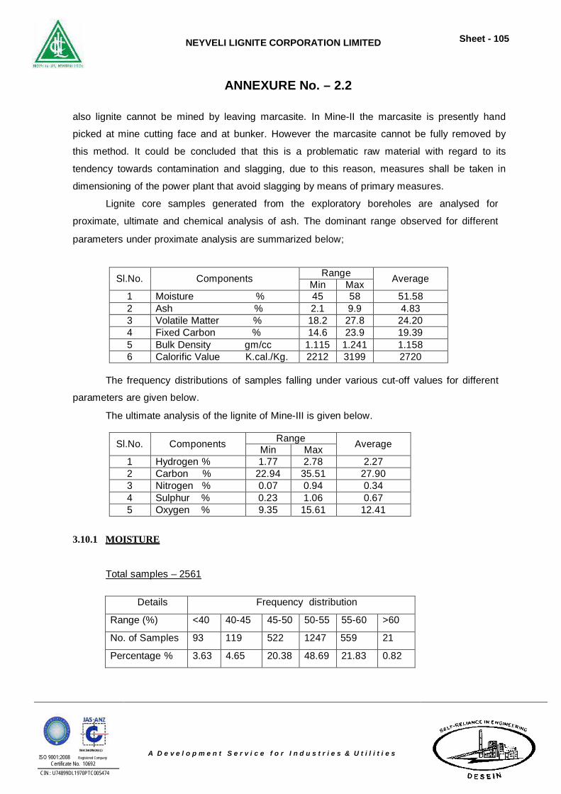
NEYVELI LIGNITE CORPORATION LIMITED
Sheet - 105
ISO 9001:2008 Registered Company Certificate No. 10692
CIN : U74899DL1970PTC005474
A D e v e l o p m e n t S e r v i c e f o r I n d u s t r i e s & U t i l i t i e s
ANNEXURE No. – 2.2 also lignite cannot be mined by leaving marcasite. In Mine-II the marcasite is presently hand
picked at mine cutting face and at bunker. However the marcasite cannot be fully removed by
this method. It could be concluded that this is a problematic raw material with regard to its
tendency towards contamination and slagging, due to this reason, measures shall be taken in
dimensioning of the power plant that avoid slagging by means of primary measures.
Lignite core samples generated from the exploratory boreholes are analysed for
proximate, ultimate and chemical analysis of ash. The dominant range observed for different
parameters under proximate analysis are summarized below;
Sl.No.
Components Range
Average Min Max 1 Moisture % 45 58 51.58 2 Ash % 2.1 9.9 4.83 3 Volatile Matter % 18.2 27.8 24.20 4 Fixed Carbon % 14.6 23.9 19.39 5 Bulk Density gm/cc 1.115 1.241 1.158 6 Calorific Value K.cal./Kg. 2212 3199 2720
The frequency distributions of samples falling under various cut-off values for different
parameters are given below.
The ultimate analysis of the lignite of Mine-III is given below.
Sl.No.
Components Range
Average Min Max 1 Hydrogen % 1.77 2.78 2.27 2 Carbon % 22.94 35.51 27.90 3 Nitrogen % 0.07 0.94 0.34 4 Sulphur % 0.23 1.06 0.67 5 Oxygen % 9.35 15.61 12.41
3.10.1 MOISTURE
Total samples – 2561
Details Frequency distribution Range (%) <40 40-45 45-50 50-55 55-60 >60 No. of Samples 93 119 522 1247 559 21 Percentage % 3.63 4.65 20.38 48.69 21.83 0.82
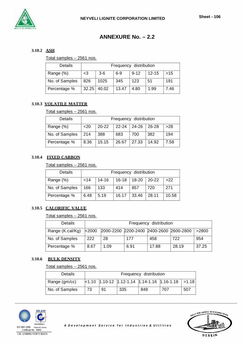
NEYVELI LIGNITE CORPORATION LIMITED
Sheet - 106
ISO 9001:2008 Registered Company Certificate No. 10692
CIN : U74899DL1970PTC005474
A D e v e l o p m e n t S e r v i c e f o r I n d u s t r i e s & U t i l i t i e s
ANNEXURE No. – 2.2 3.10.2 ASH
Total samples – 2561 nos.
Details Frequency distribution Range (%) <3 3-6 6-9 9-12 12-15 >15 No. of Samples 826 1025 345 123 51 191 Percentage % 32.25 40.02 13.47 4.80 1.99 7.46
3.10.3 VOLATILE MATTER
Total samples – 2561 nos.
Details Frequency distribution Range (%) <20 20-22 22-24 24-26 26-28 >28 No. of Samples 214 388 683 700 382 194 Percentage % 8.36 15.15 26.67 27.33 14.92 7.58
3.10.4 FIXED CARBON
Total samples – 2561 nos.
Details Frequency distribution Range (%) <14 14-16 16-18 18-20 20-22 >22 No. of Samples 166 133 414 857 720 271 Percentage % 6.48 5.19 16.17 33.46 28.11 10.58
3.10.5 CALORIFIC VALUE
Total samples – 2561 nos.
Details Frequency distribution Range (K.cal/Kg) <2000 2000-2200 2200-2400 2400-2600 2600-2800 >2800 No. of Samples 222 28 177 458 722 954 Percentage % 8.67 1.09 6.91 17.88 28.19 37.25
3.10.6 BULK DENSITY
Total samples – 2561 nos.
Details Frequency distribution Range (gm/cc) <1.10 1.10-12 1.12-1.14 1.14-1.16 1.16-1.18 >1.18 No. of Samples 73 91 335 848 707 507
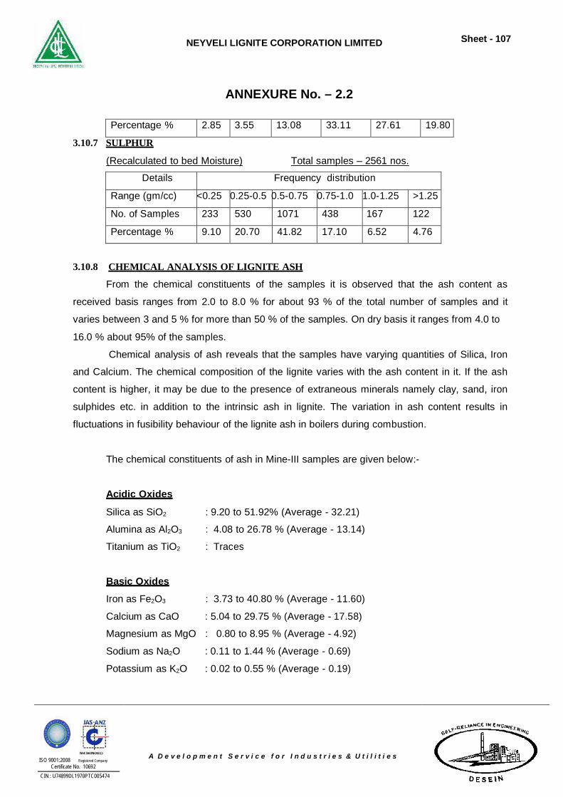
NEYVELI LIGNITE CORPORATION LIMITED
Sheet - 107
ISO 9001:2008 Registered Company Certificate No. 10692
CIN : U74899DL1970PTC005474
A D e v e l o p m e n t S e r v i c e f o r I n d u s t r i e s & U t i l i t i e s
ANNEXURE No. – 2.2
Percentage % 2.85 3.55 13.08 33.11 27.61 19.80 3.10.7 SULPHUR
(Recalculated to bed Moisture) Total samples – 2561 nos.
Details Frequency distribution Range (gm/cc) <0.25 0.25-0.5 0.5-0.75 0.75-1.0 1.0-1.25 >1.25 No. of Samples 233 530 1071 438 167 122 Percentage % 9.10 20.70 41.82 17.10 6.52 4.76
3.10.8 CHEMICAL ANALYSIS OF LIGNITE ASH
From the chemical constituents of the samples it is observed that the ash content as
received basis ranges from 2.0 to 8.0 % for about 93 % of the total number of samples and it
varies between 3 and 5 % for more than 50 % of the samples. On dry basis it ranges from 4.0 to
16.0 % about 95% of the samples.
Chemical analysis of ash reveals that the samples have varying quantities of Silica, Iron
and Calcium. The chemical composition of the lignite varies with the ash content in it. If the ash
content is higher, it may be due to the presence of extraneous minerals namely clay, sand, iron
sulphides etc. in addition to the intrinsic ash in lignite. The variation in ash content results in
fluctuations in fusibility behaviour of the lignite ash in boilers during combustion.
The chemical constituents of ash in Mine-III samples are given below:-
Acidic Oxides
Silica as SiO2 : 9.20 to 51.92% (Average - 32.21)
Alumina as Al2O3 : 4.08 to 26.78 % (Average - 13.14)
Titanium as TiO2 : Traces
Basic Oxides
Iron as Fe2O3 : 3.73 to 40.80 % (Average - 11.60)
Calcium as CaO : 5.04 to 29.75 % (Average - 17.58)
Magnesium as MgO : 0.80 to 8.95 % (Average - 4.92)
Sodium as Na2O : 0.11 to 1.44 % (Average - 0.69)
Potassium as K2O : 0.02 to 0.55 % (Average - 0.19)
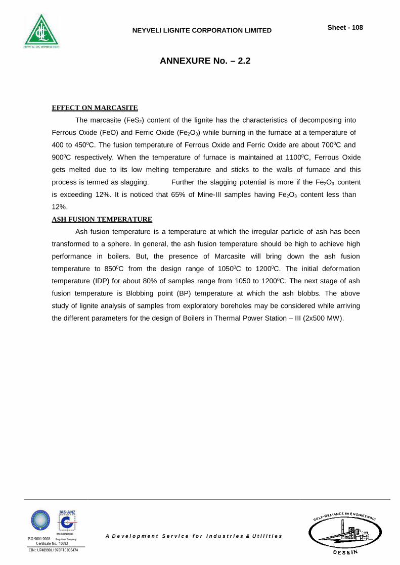
NEYVELI LIGNITE CORPORATION LIMITED
Sheet - 108
ISO 9001:2008 Registered Company Certificate No. 10692
CIN : U74899DL1970PTC005474
A D e v e l o p m e n t S e r v i c e f o r I n d u s t r i e s & U t i l i t i e s
ANNEXURE No. – 2.2 EFFECT ON MARCASITE
The marcasite (FeS2) content of the lignite has the characteristics of decomposing into
Ferrous Oxide (FeO) and Ferric Oxide (Fe2O3) while burning in the furnace at a temperature of
400 to 4500C. The fusion temperature of Ferrous Oxide and Ferric Oxide are about 7000C and
9000C respectively. When the temperature of furnace is maintained at 11000C, Ferrous Oxide
gets melted due to its low melting temperature and sticks to the walls of furnace and this
process is termed as slagging. Further the slagging potential is more if the Fe2O3 content
is exceeding 12%. It is noticed that 65% of Mine-III samples having Fe2O3 content less than
12%.
ASH FUSION TEMPERATURE
Ash fusion temperature is a temperature at which the irregular particle of ash has been
transformed to a sphere. In general, the ash fusion temperature should be high to achieve high
performance in boilers. But, the presence of Marcasite will bring down the ash fusion
temperature to 8500C from the design range of 10500C to 12000C. The initial deformation
temperature (IDP) for about 80% of samples range from 1050 to 12000C. The next stage of ash
fusion temperature is Blobbing point (BP) temperature at which the ash blobbs. The above
study of lignite analysis of samples from exploratory boreholes may be considered while arriving
the different parameters for the design of Boilers in Thermal Power Station – III (2x500 MW).
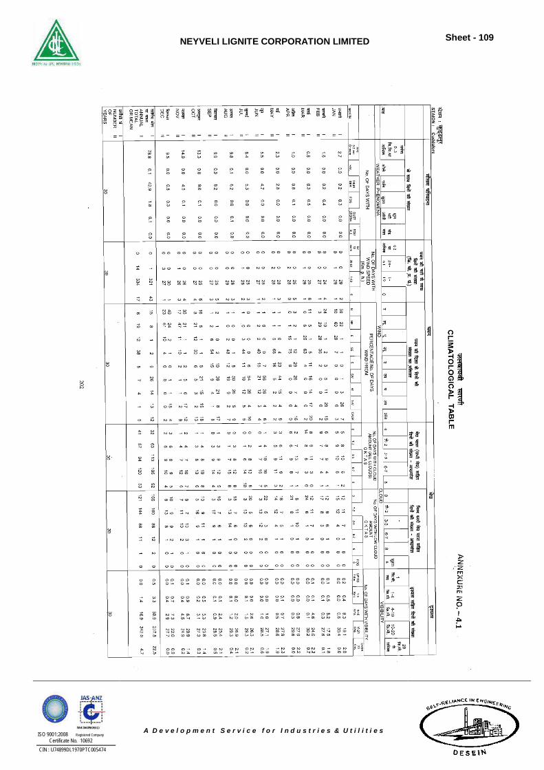
NEYVELI LIGNITE CORPORATION LIMITED
Sheet - 109
ISO 9001:2008 Registered Company Certificate No. 10692
CIN : U74899DL1970PTC005474
A D e v e l o p m e n t S e r v i c e f o r I n d u s t r i e s & U t i l i t i e s
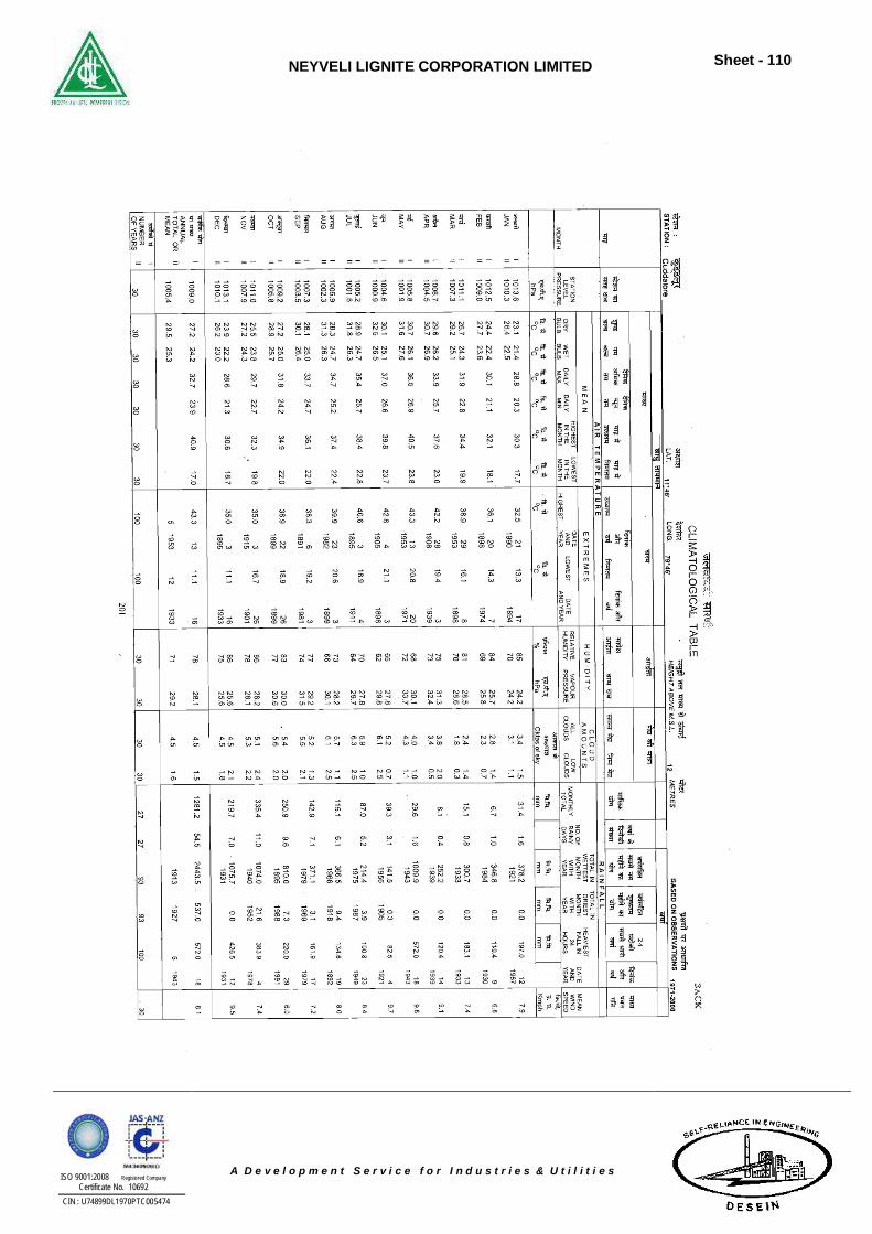
NEYVELI LIGNITE CORPORATION LIMITED
Sheet - 110
ISO 9001:2008 Registered Company Certificate No. 10692
CIN : U74899DL1970PTC005474
A D e v e l o p m e n t S e r v i c e f o r I n d u s t r i e s & U t i l i t i e s
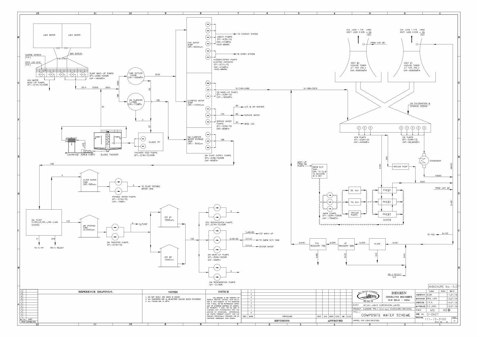
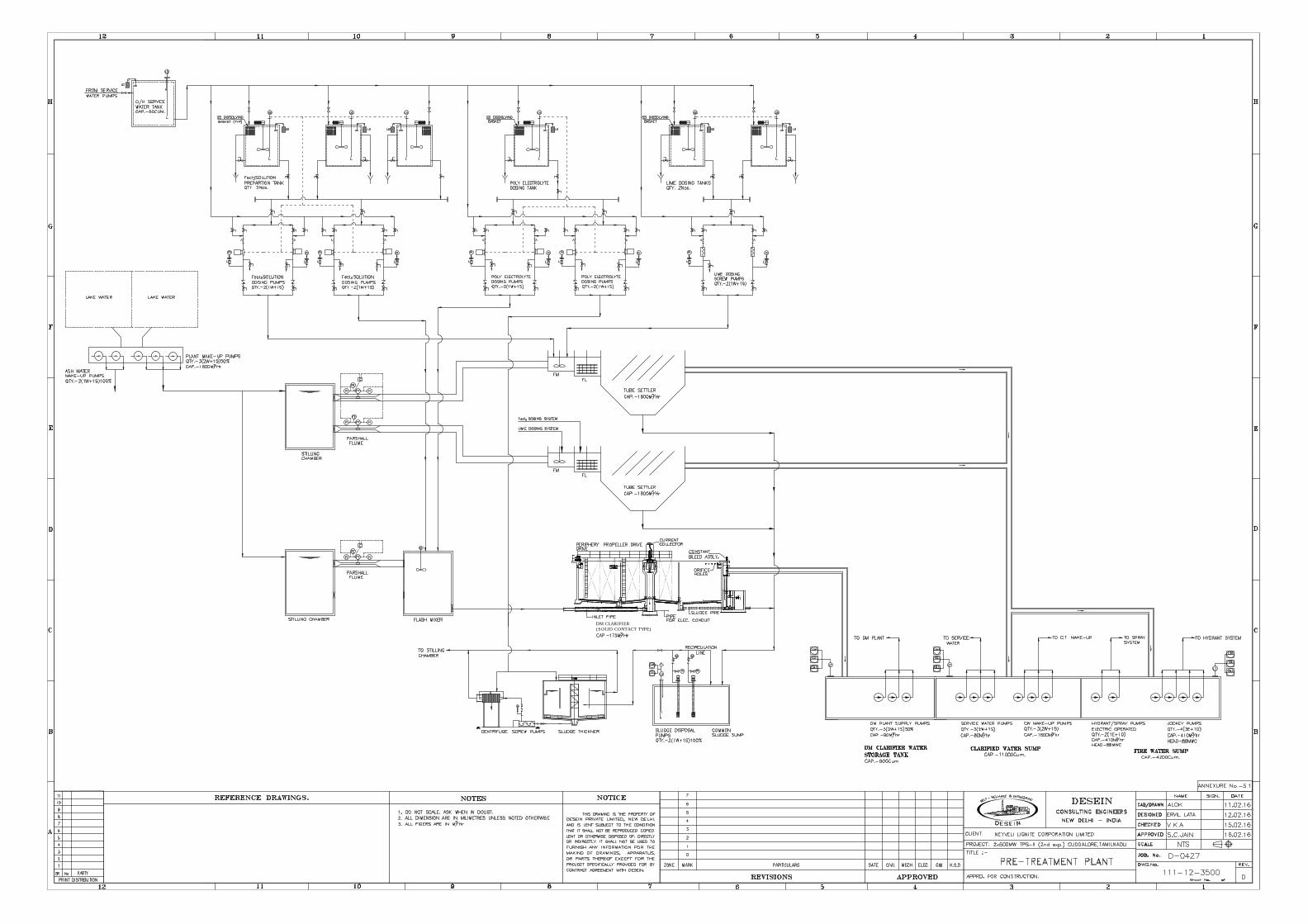
(SOLID CONTACT TYPE)
DM CLARIFIER
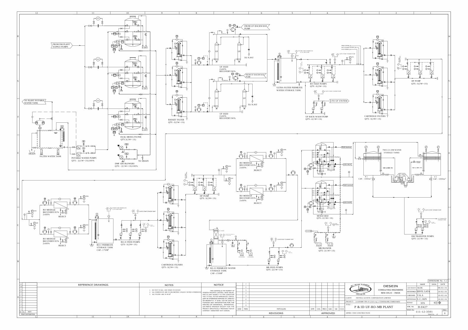
DRAIN
PG
TO N-PIT
PG
PT
IA
H
LL
UF
FT
FI FQ
PG
DPIS
BASKET FILTER
FROM UF BACKWASH
PUMP
I
PG
SAMPLING
PG
FI FQ
RO-II FEED PUMPS
RT
FIT
FI FQ
I
RT
PG
PG
AI
AE I
COND.
AI
AE
I
pH
RO FEED PUMPS
UF BACK WASH PUMP
TO UF SYSTEM
QTY.-3(2W+1S)
N.PIT
FT
L-AUTO START STANDBY PUMP
L-AUTO START STANDBY PUMP
IA
H
L
LT
LL-TO TRIP PUMP
N-PUMP START PERMISSIVE
PGPG
PTPT
PT
IA
H
LL
FG
UF
FT
FI FQ
PG
TO N.PIT
N.PIT
VENT
ULTRA FILTER PERMEATE
FROM UF BACKWASH
PUMP
WATER STORAGE TANK
I
SAMPLING
PG
FI FQ
LG
IA
H
L
LT
FT
LL-TO TRIP PUMP
N-PUMP START PERMISSIVE
MIXED BED
RT
FIT
FI FQ
I
RT
PG
PG
AI
AE I
COND.
AI
AE
I
pH
QTY.-2(1W+1S)
DPT
PG
REJECT
FT
FI
FT
FI
HP PUMP
QTY.-3(2W+1S)
DPIS
DPAH
PG
DPIS
PG
QTY.-3(2W+1S)
UF
TO N.PIT
DPIS
DPAH
PG
DPT
PG
FT
FI
FT
FI
RO MODULE
RECOVERY 85%
RO-I PERMEATE
STORAGE TANK
CAP.-170M
DPIS
DPAH
PG
DPIS
PG
HP PUMP
QTY.-3(2W+1S)
DPIS
DPAH
PG
DPT
PG
REJECT
FT
FI
FT
FI
KE
DPT
PG
FT
FI
FT
FI
RO MODULE
RECOVERY 85%
DRAIN
FROM DM PLANT
POTABLE WATER PUMPS
QTY.- 2(1W+1S)100%
LS
FILTER WATER TANK
TO PLANT POTABLE
N-PIT
DMF AIR BLOWERS
QTY.- 2(1W+1S)100%
FT
FT
CARTRIDGE FILTERS
QTY.-3(2W+1S)MB FEED PUMPS
QTY.-2(1W+1S)
PG
DRAIN
DG BLOWER DG BLOWER
PG
N.PIT
LG
DG TOWER
IA
H
L
LT
LL-TO TRIP PUMP
N-PUMP START PERMISSIVE
PT
LL-TO TRIP
I
A
H
L
PUMP (TYP)
PG
PT
PT
IA
H
LL
FG
PG
PT
RO-II PERMEATE WATER
STORAGE TANK
PH
KE
PH
TO DRAIN
MB BLOWER
QTY.-2(1W+1S)
QTY.-3(2W+1S)
CARTRIDGE FILTERS
QTY.-3(2W+1S)
WATER TANK
UF SKID
2x60%
ERVIL LATA
12
12
B
A
H
G
F
E
D
C
11 10 9 8 7
6
11 10 9 8 7 6
5 4
PROJECT:
CLIENT:
APPRD. FOR CONSTRUCTION:
3 2
CAD/DRAWN
1
B
5 4 3 2 1
C
D
E
F
G
H
TITLE :-
ALOK
S.C.JAIN
NTS
08.02.16
0
111-12-3501
D-0427
NEYVELI LIGNITE CORPORATION LIMITED
P & ID UF-RO-MB PLANT
2x500MW TPS-II (2nd exp.) CUDDALORE,TAMILNADU
1. DO NOT SCALE, ASK WHEN IN DOUBT.
2. ALL DIMENSION ARE IN MILIMETRES UNLESS NOTED OTHERWISE
3. ALL FIGERS ARE IN M/Hr
3
V.K.A
10.02.16
QTY.-2(1W+1S)
TWO (2) DM WATER
3
CAP : 1000m
STORAGE TANKS
SERVICE
WATER
#1
3
CAP : 1000m
#2
FILTERED
DRY
CHAMBER
SIG
HT G
LASS
CHEMICAL
FILL PLUG
300NB
AIR
ENTRY
AIR TIGHT
VESSEL
DRAIN
PLUG
10% NaOH
DRAIN
SUMP
WATER
FILTERED
WATER
DM TRANSFER PUMPS
QTY.-2(1W+1S)
PT
IA
H
LL
LL-TO TRIP
I
A
H
L
PUMP (TYP)
PG
PT
PG
PT
TO CONDENSATE
STORAGE TANK
SUPPLY PUMPS
10.02.16
10.02.16
N-PIT
UF
REJECT
RO MODULE
RECOVERY 85%
REJECT
RO MODULE
RECOVERY 85%
DPIS
DPAH
PG
2x60%
2x60%
LL-TO TRIP
IA
H
L
PUMP (TYP)
PG
PT
2x60%
2x60%
KE
PH
RECOVERY 90%
UF SKID
2x60%
RECOVERY 90%
DPIS
PG
FT
DUAL MEDIA FILTER
QTY.3(2W+1S)
N-PIT
KE
PH
KE
KE
3
CAP.-150M
3
ANNEXURE No.-5.2
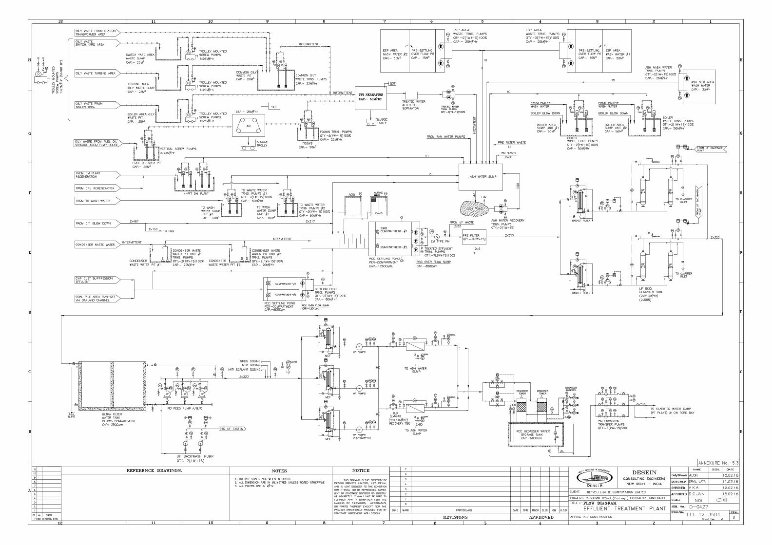
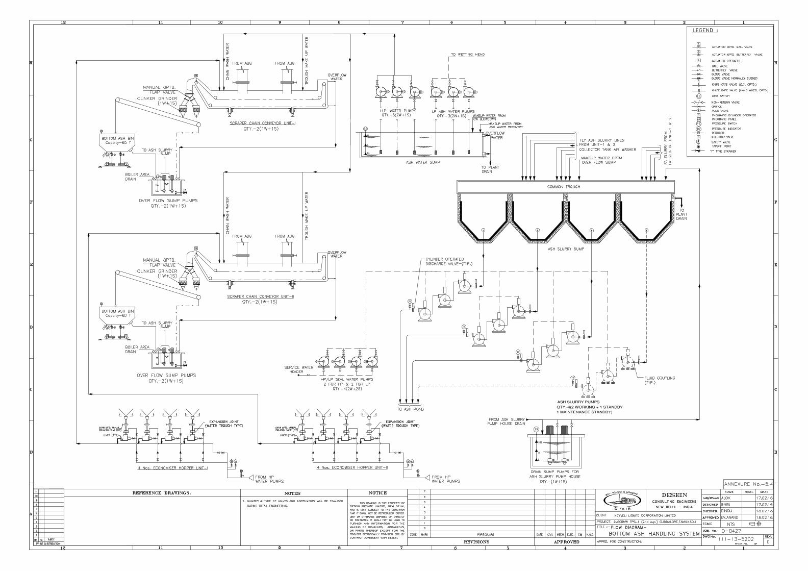
LS
H
DL
L
M MMMM M
A
A
S
PP
A
C
L
H
HH
LS
M MM M
PI
PI
PI
PI
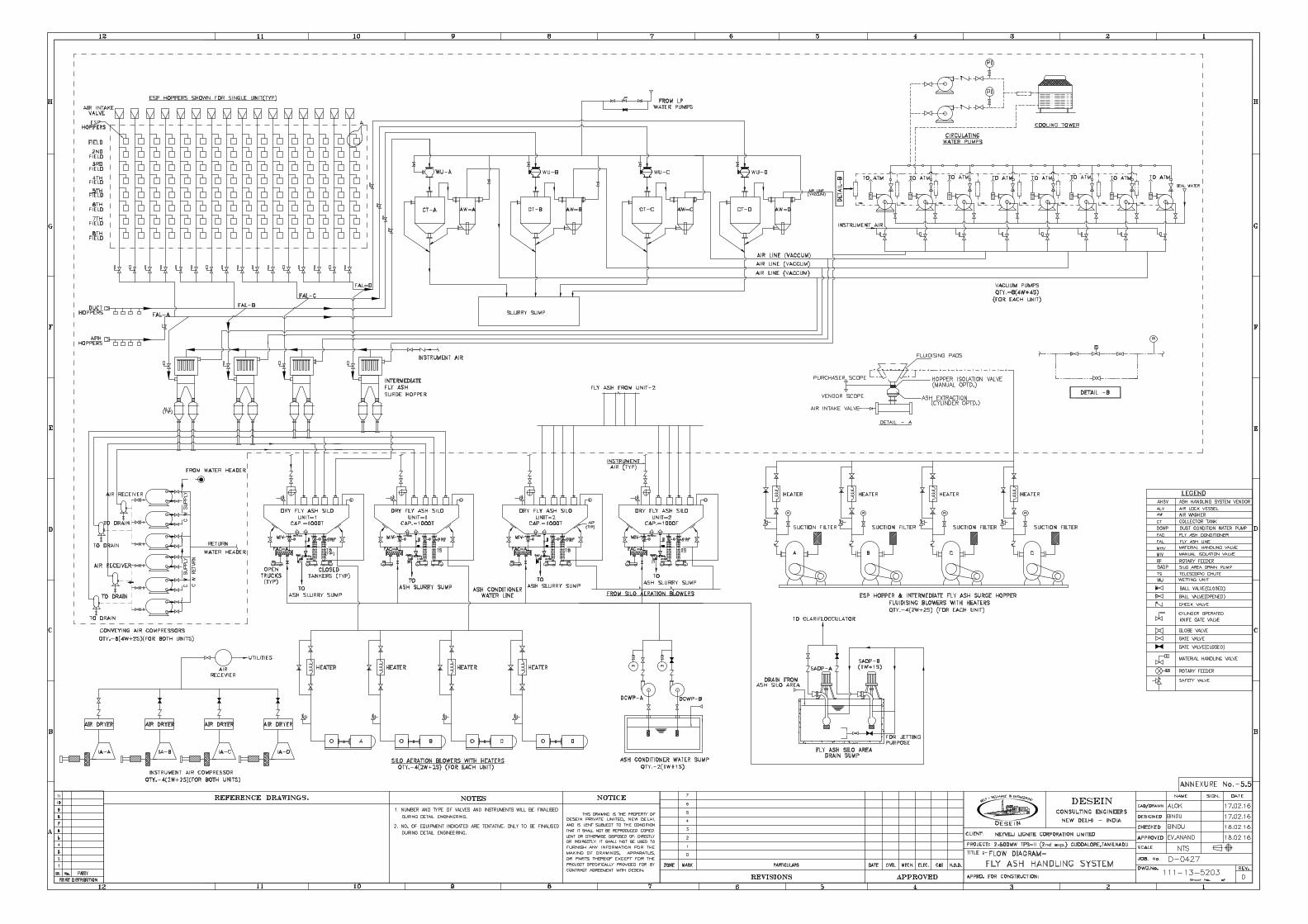
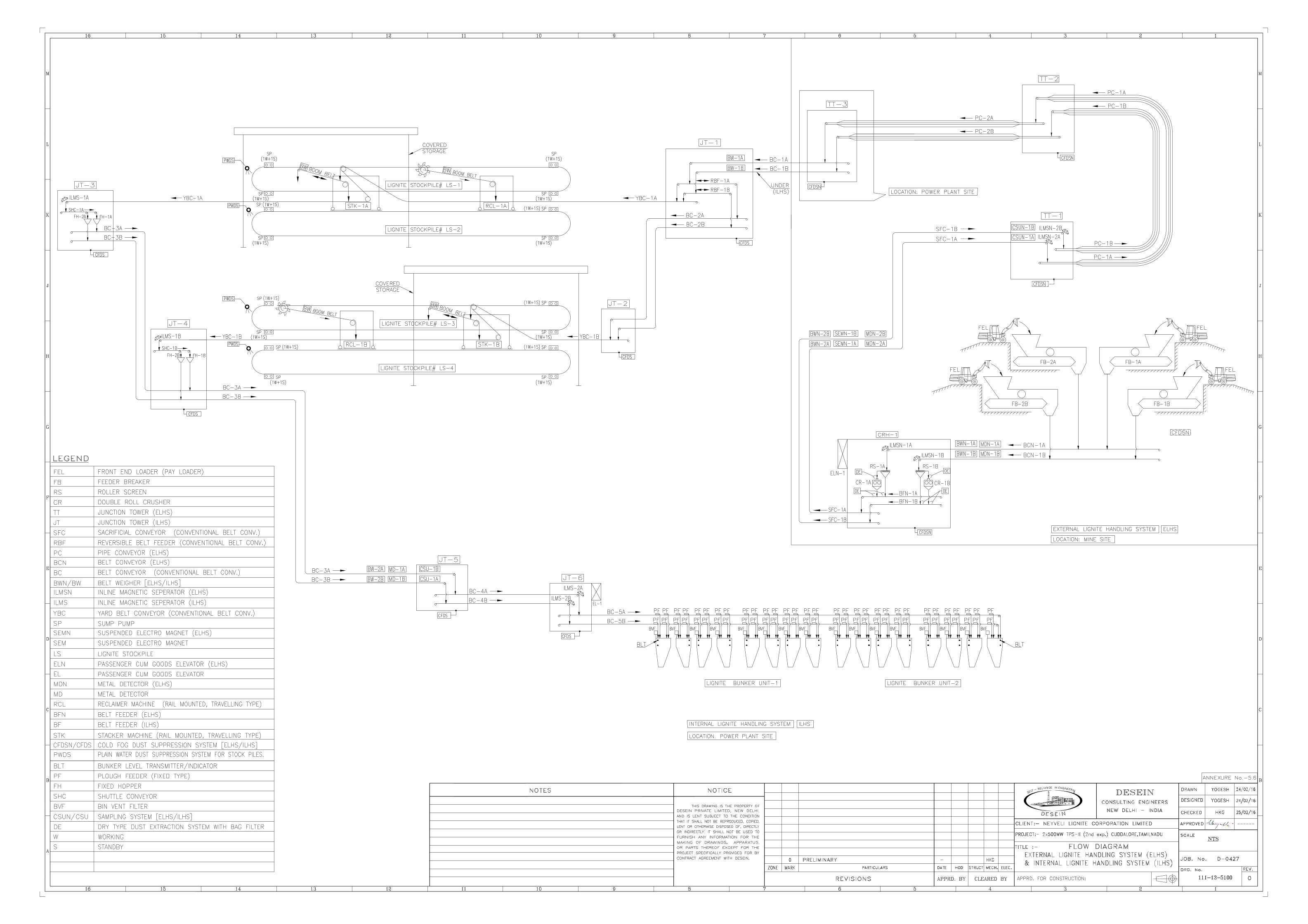
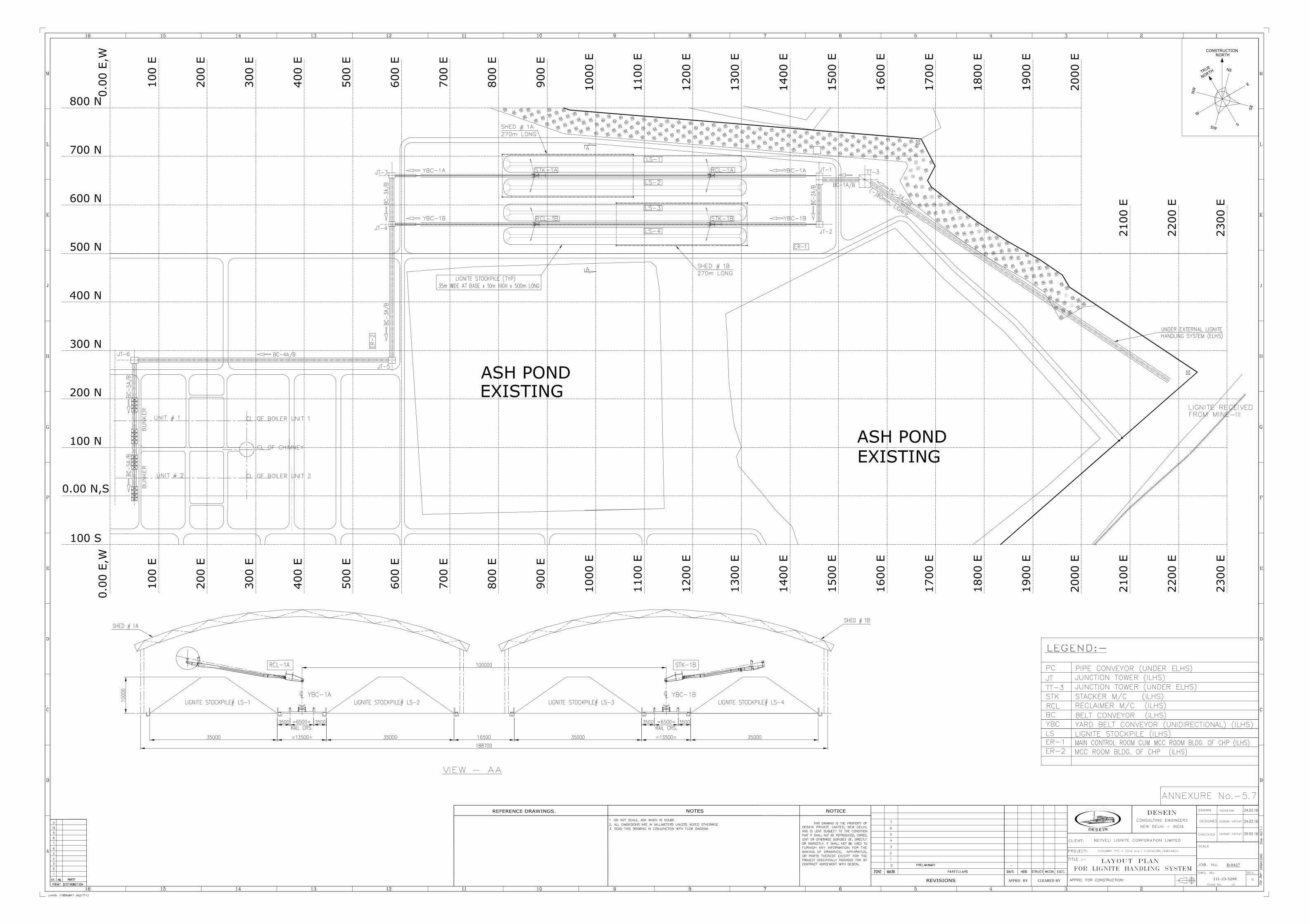
CLEARED BY
D-0427
APPRD. BY
111-23-5200
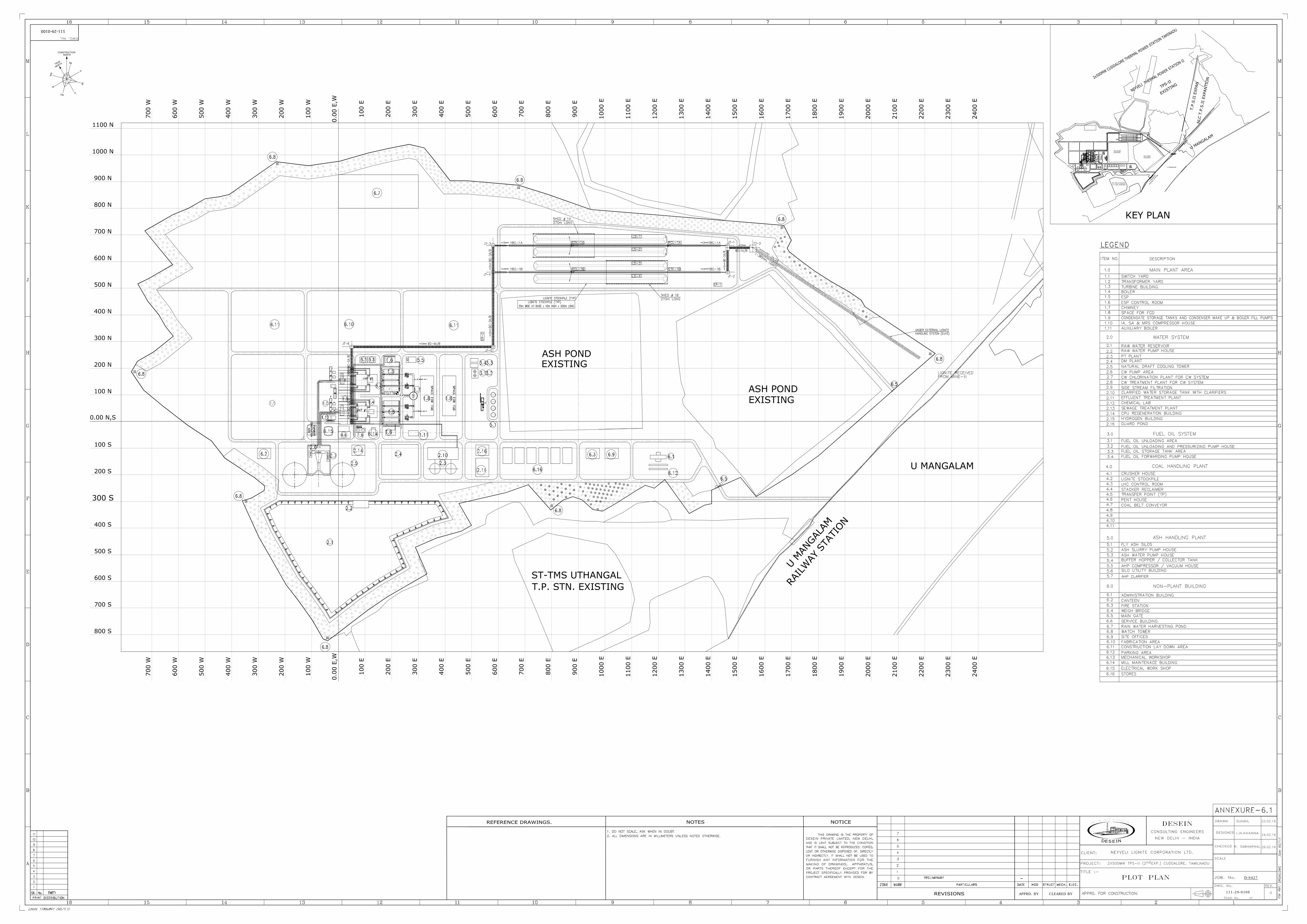
P A S S A G
E
AIR W
ASH
ER
BU
ILD
IN
G
DG
H
OU
SE
(CO
MM
ON
)
CO
MPRESSO
R
HO
USE
AIR W
ASH
ER
BU
ILD
IN
G
01
2X500MW TPS-II (2 EXP.) CUDDALORE, TAMILNADU
CLEARED BY
D-0427
APPRD. BY
111-29-0100
22.02.16
24.02.16
26.02.16
nd
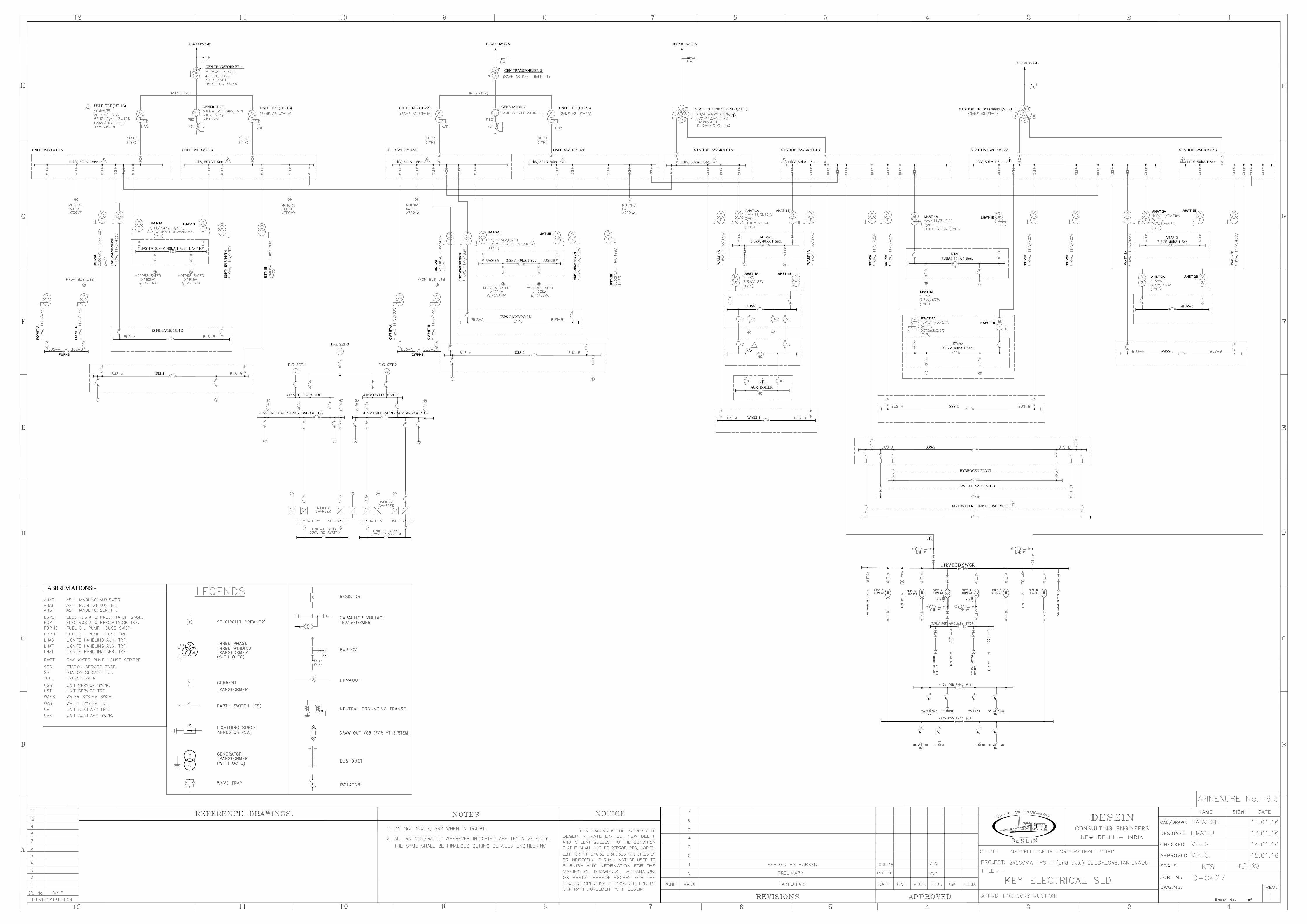
GEN.TRANSFORMER-1
UNIT TRF (UT-1A)
UNIT SWGR #U1BUNIT SWGR #U1A
ESPS-1A/1B/1C/1D
USS-1
US
T-1A
ES
PT
-1A
/1B
/1C
/1D
ES
PT
-1E
/1F
/1G
/1H
US
T-1B
GENERATOR-1
3.3kV, 40kA 1 Sec.
UNIT TRF (UT-1B)
FO
PH
T-A
FO
PH
T-B
GEN.TRANSFORMER-2
UNIT TRF (UT-2A)
UNIT SWGR #U2BUNIT SWGR #U2A
ESPS-2A/2B/2C/2D
USS-2
US
T-2A
ES
PT
-2A
/2B
/2C
/2D
ES
PT
-2E
/2F
/2G
/2H
US
T-2B
GENERATOR-2
3.3kV, 40kA 1 Sec.
UNIT TRF (UT-2B)
CW
PH
T-A
CW
PH
T-B
STATION TRANSFORMER(ST-1)
HYDROGEN PLANT
SWITCH YARD ACDB
SSS-2
WASS-1
W
AS
T-2A
STATION TRANSFORMER(ST-2)
AHAS-1
AHST-1A AHST-1B
AHAS-2
AHAS-2
AHST-2AAHST-2B
WASS-2
FOPHS
UAT-1A
UAT-1B
UAT-2A
UAT-2B
CWPHS
WA
ST
-1A
AHAT-1BAHAT-1A
AHSS
AHAT-2B
AHAT-2A
W
AS
T-2B
LHAS
LHAT-1A
LHST-1A
SSS-1
SS
T-1B
SS
T-2B
SS
T-1A
SS
T-2A
LHAT-1B
RWAS
RWAT-1A
RAWT-1B
11kV, 50kA 1 Sec.
STATION SWGR #C1ASTATION SWGR #C1B STATION SWGR #C2A STATION SWGR #C2B
11kV, 50kA 1 Sec. 11kV, 50kA 1 Sec. 11kV, 50kA 1 Sec.
11kV, 50kA 1 Sec.
11kV, 50kA 1 Sec. 11kV, 50kA 1 Sec. 11kV, 50kA 1 Sec.
3.3kV, 40kA 1 Sec.
3.3kV, 40kA 1 Sec.
3.3kV, 40kA 1 Sec.
3.3kV, 40kA 1 Sec.
D.G. SET-1
D.G. SET-3
D.G. SET-2
415V DG PCC # 1DF 415V DG PCC # 2DF
415V UNIT EMERGENCY SWBD # 1DG 415V UNIT EMERGENCY SWBD # 2DG
WA
ST
-1A
UAS-1A UAS-1B
UAS-2A UAS-2B
TO 230 Kv GIS
TO 230 Kv GISTO 400 Kv GISTO 400 Kv GIS
ABBREVIATIONS:-
FIRE WATER PUMP HOUSE MCC
BAS
AUX. BOILER
11kV FGD SWGR.
1
11
1
11
111
1
1
1
1
1
1
1