Embed Size (px)
Citation preview

57PCI Journal | January–February 2018
In this world of increasingly scarce resources and constrained budgets, it has become more critical to find and implement innovation. Every dollar must be made
to stretch, and consideration must be given to new meth-ods of building structures. Shape-memory alloys (SMAs) and engineered cementitious composites (ECCs) provide an opportunity for innovation. The initial installation will cost extra money for materials and installation; however, the long-term payoff could be considerable. A new seismic design paradigm may be entered, where bridges move from a seismic design of “no collapse” to one of “no damage.” If so, the value of this innovation will be immense: there may be structures that are immediately usable after an earthquake, not only for emergency vehicles, but also for the public.
Bridges constructed with precast, prestressed concrete girders have a proven economic value, require little or no maintenance, and are aesthetically pleasing. Some of the advantages of the spliced-girder concept are longer spans, fewer substructure units, increased girder spacing, rapid construction, enhanced aesthetics, and reduced superstruc-ture depths.
Although the design requirements for spliced-girder bridg-es are not significantly different from those of conventional
■ The reconstruction of the State Route 99 Alaskan Way Viaduct south access connection bridge in Seattle, Wash., allowed for innovative bridge design.
■ The bridge substructure consists of two intermedi-ate piers using shape-memory alloy (SMA) along with engineered cementitious composite (ECC) in plastic-hinged zones of the columns
■ The focus of this paper is the experimental and ana-lytical studies that were undertaken to evaluate and optimize SMA ECC columns.
Precast concrete spliced-girder bridge in Washington State using superelastic materials in bridge columns to improve seismic resiliency: From research to practice
Tom Baker, M. Saiid Saiidi, Brian Nakashoji, Jed Bingle, Tim Moore, and Bijan Khaleghi
58 PCI Journal | January–February 2018
Previous research on columns with NiTi SMA-reinforced plastic-hinged zones has demonstrated the feasibility of this combination to resist earthquake forces, minimize damage, and nearly eliminate residual displacements under strong earthquakes.4–7 These column models had several common features:
• the cross section was circular
• ECC was used over approximately 1.5 to 2.0 times the column diameter
• the SMA bars were machined to a dog-bone shape
• the SMA bar length in the plastic-hinge zone was at least the same as the column diameter
• the SMA bars were spliced to steel reinforcing bars using threaded couplers
The aspect ratio of the columns (height over diameter) ranged from 3 to 4.5. The satisfactory performance of these column models prompted the implementation of the SMA ECC technology in a highway bridge in the state of Washington.
Superstructure design and construction features
The AWV-SAC bridge uses Washington State Department of Transportation (WSDOT) precast concrete spliced-gird-er trapezoidal tub girder section U72PTG6. Using post-ten-sioning, precast concrete beam-type elements are joined longitudinally to form the complete girder. The resulting superstructure cross section is a conventional beam-and-slab system with a composite cast-in-place concrete deck. Among the reasons to use spliced girders are a reduction of substructure units due to increased span lengths, a reduc-tion of girder units due to increased girder spacing, a re-duction in shipping weight, and functionality and aesthetic improvements by reducing superstructure depth. Figure 1 shows the elevation of the AWV-SAC bridge.
prestressed concrete girder bridges, the analysis procedure must take into account additional considerations. Among the most relevant of these considerations are staged construction, multiple stressing stages, and combined pretensioning and post-tensioning. Thus, the design of spliced-girder bridges involves greater complexity than is required for conventional precast, prestressed concrete girder designs.
Splicing of precast concrete tub girders may be beneficial because the significant weight of the cross section may exceed the usual limits for handling and transportation. Precast concrete I-girder and deck bulb-tee girder bridges may also be fabricated in segments and spliced longitudinally.
Current bridge seismic design could be improved by innovative designs that keep bridges operational and repair costs to a minimum by reducing damage to columns in plastic-hinged zones and minimizing residual drifts. These objectives can be accomplished by using innova-tive materials, such as superelastic nickel-titanium (NiTi) SMA and ECC. The role of SMA is to minimize residual displacements, and the role of ECC is to eliminate damage under design earthquake and minimize damage under the maximum considered earthquake (MCE). This project and companion study focused on evaluating the performance of SMA ECC in scaled bridge columns representing the piers of the SR 99 Alaskan Way Viaduct south access connection (AWV-SAC) bridge off-ramp structure that is under construction in Seattle, Wash.
SMA has the unique property of recovering strains even after it yields. The strain recovery is either through heating (the shape-memory effect) or stress removal (superelastic effect). Structural characteristics of NiTi are discussed in Desroches and Smith.1 Preliminary structural specifica-tions for NiTi were developed by Tazarv and Saiidi.2 The superior properties of ECC over conventional concrete and cement grouts have been established through various studies.3 The properties of SMA and ECC are discussed in more details in subsequent sections.
Figure 1. Alaskan Way Viaduct south access connection bridge elevation. Note: 1 ft = 0.305 m.
Back of pavement seat
Expansion
Retainingwall
Finished ground lineRoadway below bridge
8 ft diameter shaft foundation (typical at interior piers)
Retainingwall
Fixed Fixed Expansion
110 ft 180 ft 110 ftBack of pavement seatCenterline pier Centerline pier
59PCI Journal | January–February 2018
• strength of concrete for girders is 6.0 ksi (41 MPa) at transfer and 7.0 ksi (48 MPa) at final
• 0.6 in. diameter low-relaxation prestressing strand Grade 270 (1860 MPa) for pretensioning strands
• design for 2 in. (50 mm) future hot mix asphalt overlay with a density of 140 lb/ft3 (2240 kg/m3)
• strength of concrete for cast-in-place concrete closure is 5.0 ksi (34 MPa)
• strength of concrete for cast-in-place concrete bridge deck is 5.0 ksi (WSDOT Class 5000D)
• cast-in-place concrete intermediate diaphragms for spliced girders
Prestress losses in spliced precast concrete girder bridges are estimated using the provisions of AASHTO LRFD specifications with considerations for the effects of com-bined pretensioning and post-tensioning. When required, the effects of creep and shrinkage in spliced precast con-crete girder bridges are estimated with considerations for time-dependent parameters.
Stress limits for temporary concrete stresses in girder seg-ments before losses and stress limits for concrete stresses in girder segments at the service limit state after losses specified in the AASHTO LRFD specifications are consid-ered at each stage of pretensioning or post-tensioning with consideration for all applicable loads during construction. The compressive strength of concrete at time of initial prestress '
cif is used in the stress limits.
Allowable stresses for prestressing strands used in precast concrete segments are 0.75f
pu at transfer and 0.8f
py at ser-
vice limit state, where fpu
is the tensile strength and fpy
is the yield strength of prestressing steel. The allowable stresses for post-tensioning strands are 0.8f
pu at jacking and 0.75f
pu
at the end of the zone affected by seating loss. The anchor
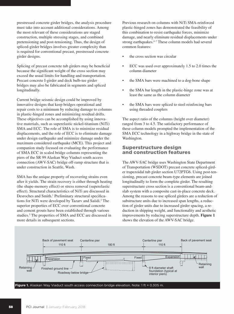
The bridge cross section is composed of girders with a cast-in-place concrete composite deck rather than precasting the full width and depth of the superstructure as one piece (Fig. 2). In some cases, the deck may be integrally cast with each girder. Connecting the girders across the longitudinal joints completes a bridge of this type.
The method of construction and any required temporary support are important in the design of spliced precast concrete girder bridges. Such considerations often govern final conditions in the selection of section dimensions and reinforcement or prestressing.
Design considerations for WSDOT spliced girders
The design of spliced-girder bridges depends on sever-al parameters that significantly influence performance and cost. The most relevant are time-dependent effects, splicing locations, construction sequences, girder segment geometries, number of beams, and number or profiles of pretensioned and post-tensioned reinforcement. The design of precast concrete segments as well as precast, post-ten-sioned concrete members is based on the requirements for both allowable stress design and ultimate strength using the American Association of State Highway and Transpor-tation Officials’ AASHTO LRFD Bridge Design Specifi-cations8 and additional criteria detailed in the WSDOT Bridge Design Manual.9 The design criteria for spliced girders are as follows:
• design for zero tension at service III limit state
• simple-span girder design for all permanent and tran-sient loads
• gross section properties for all designs
• refined estimate of time-dependent prestress losses
• relative humidity of 75% under normal exposure
Figure 2. Alaskan Way Viaduct south access connection bridge typical section. Note: 1 in. = 25.4 mm; 1 ft = 0.305 m.
30 ft 6 in.Bridge roadway
8 in.bridgedeck
Girder A workline
Centerline girder A Centerline girder B
45° fillet (typical)
U72PTG6 girder (typical)
Girder B workline
16 ft 6 in.Girder spacing
60 PCI Journal | January–February 2018
system. The nonlinear strain compatibility analysis method in PCI Journal10 is recommended. In addition to the effec-tive area of the deck, the top flange of the girder and the mild steel reinforcement in the deck and the top flange of the girder may be included in the analysis.
Integral pier connection
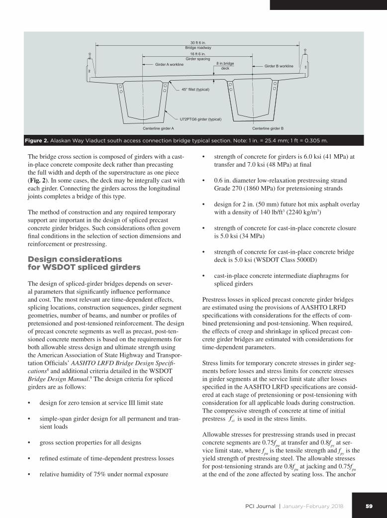
For the typical Type 1 earthquake–resisting system provid-ing a ductile substructure and essentially elastic superstruc-ture,9 capacity protection of the superstructure and how it is provided by reinforcement in the bridge deck, post-ten-sioning strand, and pretensioning strand extended from the bottom flange need to be addressed. Because the structure is post-tensioned after the crossbeams at intermediate piers have been cast, the plastic moment from the column has to overcome the applied compressive stress before tensile stress is applied to the bridge deck reinforcement and the extended strands. Extended bottom prestressing strands are used to connect the ends of girders with diaphragms and resist loads from creep effects, shrinkage effects, and positive moments.
Extended strands must be developed in the short dis-tance within the diaphragm (between two girder ends at intermediate piers). This is normally accomplished by
set for post-tensioning tendons is 3∕8 in. (9.5 mm), and stress in post-tensioning strands after seating loss is limited to 0.7f
pu.
Adequate reinforcement is provided to confine tendons at cast-in-place concrete closures and at intermediate pier diaphragms. The reinforcement is proportioned to ensure that the steel stress during the jacking operation does not exceed 0.6f
y.
Stress limits for temporary concrete stresses in joints before losses apply at each stage of post-tensioning. The compressive strength of concrete at the time of initial pre-stress '
cif is used in the stress limits.
Stress limits for concrete stresses in joints at the service limit state after losses apply. These stress limits also apply for intermediate load stages, with the compressive strength of concrete '
cf at time of loading being used in the stress limits. The compressive strength of the closure joint concrete at a specified age is compatible with design stress limitations.
For precast, prestressed concrete girders, the approximate methods of the AASHTO LRFD specifications underes-timate the flexural strength of the composite deck-girder
No. 6 stirrup (typical)
No. 6
No. 14 bundled(typical)
Centerline pierBridge deck reinforcement (typical)
Top of precast concretetub girder
Construction joint withroughened surface
Girder extended strands (typical)
No. 7 (typical at bottom of crossbeam)
Strand tie, typical at eachextended strand pair
Two
no. 7
spa
ced
at 6
in. =
5 ft
A
djus
t to
clea
r duc
ts.
9 in
.
No. 5 tie (typical)
5 ft 3 in.(typical)
Figure 3. Extended bottom prestressing strands. Note: no. 5 = 16M; no. 6 = 19M; no. 7 = 22M; no. 14 = 43M; 1 in. = 25.4 mm; 1 ft = 0.305 m.

61PCI Journal | January–February 2018
Dc = diameter or width of column
Ds = depth of superstructure from top of column to
top of deck slab
Construction of spliced girders
Cast-in-place concrete intermediate diaphragms were pro-vided for the AWV-SAC spliced-girder bridge to improve the construction of the post-tensioned spliced girders. Cast-in-place concrete intermediate diaphragms at 1∕3 points were used for span 2 and at midpoints for spans 1 and 3. The centerline of the intermediate diaphragms shall not be closer than 3 ft (0.9 m) from the centerline of the cast-in-place concrete closures.
Intermediate diaphragms were provided both inside and be-tween the prestressed concrete tub girders. The diaphragm inside the tub may be cast in the field or at the fabrication plant, while the diaphragms between the tubs are cast in the field. For the AWV-SAC bridge, all intermediate dia-phragms were cast in the field. Inserts are used to accom-modate the construction of the intermediate diaphragms for connections between the diaphragm and the web of precast concrete girders. Open holes were provided in each interior web, through which reinforcement could be placed. For the portion of diaphragm between the tub girders, all diaphragm and construction loads on the diaphragm before deck placement will be resisted by inserts because the concrete face and shear keys on the sloped web faces may not be effective in resisting interface shear.
The bottom of the intermediate diaphragms inside the tub was placed at least 3 in. (75 mm) above the bottom of the web so as not to impede drainage inside the tub girder. Drain holes are provided at the low point of the tub girders at the centerline of the bottom flange.
Closure joints between segments
WSDOT requires cast-in-place concrete closure joints in spliced-girder construction. The sequence of placing concrete for the closure joints and deck is specified in the contract documents. Each spliced-girder closure for the AWC-SAC bridge was 2 ft (0.6 m) wide (Fig. 4).
The intent of this closure width was to allow proper com-paction of concrete in the cast-in-place concrete closure joint. Longer closure joints could be used to provide more room to accommodate tolerances for potential misalign-ment of ducts within girder segments and misalignment of girder segments at erection.
Shear transfer at closures between the cast-in-place and precast concrete segments is through the saw teeth provid-ed at the ends of precast concrete segments.
requiring strand chucks and anchors. Figure 3 shows the extended strand detail for positive moment connection with strand anchors that are normally installed at 21 in. (530 mm) from the girder ends. The AWV-SAC bridge used eight extended straight 0.6 in. (15 mm) diameter low-relaxation strands to develop the required capacity at the end of each girder segment.
For fixed intermediate piers at the Extreme Event I limit state, Eq. (1)9 calculates the minimum number of extended strands N
ps for each girder end.
Nps =12 MseiK − MSIDL( ) 10.9φAps f pyd
(1)
where
Msei
= moment due to overstrength plastic moment capacity of the column and associated over-strength plastic shear, either within or outside the effective width
K = span moment distribution factor
MSIDL
= moment due to superimposed dead loads
ϕ = flexural resistance factor = 1.0
Aps
= area of each extended strand
d = distance from top of deck slab to center of grav-ity of extended strands
For prestressed concrete girders with cast-in-place concrete deck slabs, where all girders are within the effective width for each column overlap, the plastic hinging moment at the center of gravity of the superstructure is resisted by all girders within the effective width. Equation (2)9 calculates the plastic hinging moment per girder.
Msei =
MpoCG
Ngint
(2)
where
CGpoM = plastic hinge moment at the center of gravity of
the superstructure
intgN = number of girders encompassed by the effective
width
Equation (3)9 calculates the effective width Beff
for the extended strand.
Beff
= Dc + D
s (3)
where

62 PCI Journal | January–February 2018
shall not exceed 4 in. (100 mm) for spliced I-girders and 4½ in. (114 mm) for spliced tub girders.
Post-tensioning of spliced girders
Post-tensioning was applied after placement of deck con-crete. When all post-tensioning is applied after the deck concrete is placed, fewer post-tensioning tendons and a lower concrete strength in the closure joint are required. However, future deck replacement, if necessary, is difficult to accommodate with this construction sequence.
When all post-tensioning is applied before the deck concrete is placed, a greater number of post-tensioning tendons and higher concrete strengths in the closure joints may be required.
All post-tensioning tendons are fully grouted after stressing. Prior to grouting of post-tensioning ducts, gross cross-section properties are reduced by deducting the area of ducts and void areas around tendon couplers.
The design of WSDOT spliced girders is based on 4½ in.
The length of closure joints between precast concrete seg-ments allows for the splicing of reinforcing steel required by design considerations and for splicing of post-tension-ing ducts. The length of a closure joint is not less than 2 ft (0.6 m). Web reinforcement within the joint is the larger of that provided in the adjacent girders. The faces of the precast concrete segments at closure joints are specified as intentionally roughened surfaces. Projected bars from precast concrete segments were staggered to avoid inter-ference between bars.
When cast-in-place concrete crossbeam diaphragms are placed between precast concrete segments, the concrete cover at the cast-in-place concrete closures shall not be less than 2½ in. (63.5 mm). This increase in concrete cover is not necessary if intermediate diaphragm locations are away from the cast-in-place concrete closures. Forms at the cast-in-place concrete closures and intermediate pier dia-phragms were required to be removed to inspect for con-crete consolidation prior to post-tensioning and grouting. The clear spacing between ducts at cast-in-place concrete closures of pier diaphragms was 2 in. (50 mm) minimum. The duct diameter for WSDOT standard spliced girders
Inside ofcurve
Constructionjoint with
roughenedsurface(typical)
Construction joint with roughened surface (typical)
Centerline temporary supportand intermediate diaphragm
Ties and stirrups1 ft
2 in. (typical)
6 in. (typical)
No. 7 with 1 ft 10 in. lap splice (typical)
No. 5
No. 42 ft closure
4 in. heat shrink sleave
End of precastconcrete segments
Elevation closure
Duct splice detail
No. 6 and extended strands
See splice detail
1 ft
135° fieldbend typical
Centerline duct Centerline web
Top of bridge deck
No. 7 (typical at top)
No. 5 (typical in webs)
No. 5 (typical)No. 6
(typical)
No. 5 (typical)
No. 4
3 in. 3 in.1 ft 6 in.
No. 4
No. 4No. 5
Ties (typical)
Extended strands (typical)
Figure 4. Cast-in-place concrete closure detail. Note: no. 4 = 13M; no. 5 = 16M; no. 6 = 19M; no. 7 = 22M; 1 in. = 25.4 mm; 1 ft = 0.305 m.

63PCI Journal | January–February 2018
Bridge superstructure construction sequence
The bridge is being built in three stages over three con-struction seasons of 2016, 2017, and 2018 with three separate contracts. The drilled-shaft construction was completed in the first stage to accommodate the roadway construction below the bridge (Fig. 1). The second stage includes construction of the bridge piers and superstruc-ture. The final stage of construction will complete the approach roadway embankments.
Grouting of the post-tensioning ducts proceeded according to WSDOT standard specifications using grout Type 1. Grout Type 1 is a Class C prepackaged, pumpable, non-bleed, nonshrink, and high-strength material that conforms to the requirements of AASHTO LRFD Bridge Construc-tion Specifications section 10.9.3.11 The duct joints were wrapped at the girder closure strips in accordance with the fabricator’s details and inspected on-site by the fabricator; these performed well during grouting.
Design of joints between girder segments within the span at the service limit state does not typically govern the design for the entire length of the bridge, either for
(114 mm) diameter ducts with up to twenty-two 0.6 in. (15 mm) diameter, low-relaxation strands per duct. An an-chor set of 3∕8 in. (9.5 mm), a curvature friction coefficient μ of 0.2, and a wobble friction coefficient k of 0.0002/ft (0.00066/m) are used for the design of spliced girders.
The maximum outside diameter of ducts at cast-in-place concrete closures was 4 in. (100 mm). The area of the duct was required to be at least 2.5 times the net area of the prestressing steel in the duct per the WSDOT Bridge Design Manual.
All tendons were stressed from pier 1. A stressing se-quence was required so that the prestressing force is distributed with an approximately equal amount in each web and is placed symmetrically about the centerline of the bridge. No more than one-half of the prestressing force in any web could be stressed before an equal force was stressed in the adjacent webs. No more than one-sixth of the total prestressing force could be applied eccentrically about the centerline of bridge. The push-through method of tendon placement was employed. Side forms from in-side and outside the closures and crossbeam were removed prior to post-tensioning. Figure 5 shows the post-tension-ing tendon profiles of the AWV-SAC bridge.
Back of pavement seat
Span 1 Span 2
Centerline closure
Centerline closure
Centerline closure Centerline closure
Centerline Pier 2
Centerline Pier 3 Back of pavement seat
End of tendon
High point
Point of inflection
Point of inflection
Centerline intermediate diaphragm
Centerline intermediate diaphragm
Center of gravity of post-tensioning forceParabolic curve between control points
Centerline intermediate diaphragm Centerline intermediate diaphragm
2 ft 3 in.
2 ft 3 in.
1 ft
1 ft(typical)
18 ft
3 ft
Mat
chlin
e
3 ft
1 ft
1 ft(typical)
1 ft(typical)
1 ft (typical)
1 ft
1 ft72 ft54 ft 10 in.
10 ft 6 in. 18 ft
54 ft 10 in.
End of precastconcrete segment
Segment 1-1Segment 1-2
Segment 2-3 Segment 3-1
Segment 3-2
Low pointHigh point Low point
1 ft 3½ in.
1 ft 3½ in.
4 ft 7½ in.
4 ft 7½ in.4 ft 6 in.
3 ft 4½ in.(typical)
9½ in.
3 ft 4½ in.(typical)
5 ft 5¼ in.
5 ft 5¼ in.
4 ft 6 in.Drain hole
Low point
Span 2 Span 3
Point of inflection
Point of inflection
End of tendon
End of precastconcrete segment
Figure 5. Post-tensioning tendon profile of Alaskan Way Viaduct south access connection bridge. Note: 1 in. = 25.4 mm; 1 ft = 0.305 m.

64 PCI Journal | January–February 2018
plers. The mild steel longitudinal bars are used below the plastic-hinge zone and in the column cap beam connection above the plastic-hinge zone. ECC is used over the upper 5 ft (1.5 m) (100% of the column side dimension) of the column clear heights. The longitudinal and transverse reinforcement ratios in the plastic-hinge zones are 1.06% and 1.43%, respectively.
Supporting research for innovative features
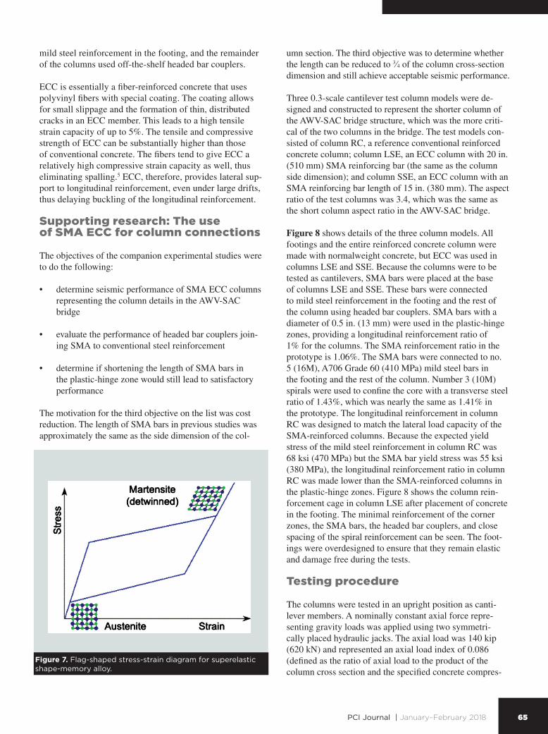
Superelastic SMAs are materials that can undergo large deformations beyond their elastic limits and yet fully recover their deformation upon stress removal. The most common type of SMA is made with approximately 44% titanium and 56% nickel. SMA bars with diameters up to 1.25 in. (31.8 mm) are available. With proper annealing, NiTi maintains its superelastic property under the wide range of ambient temperatures to which bridges are ex-posed. Figure 7 shows a characteristic, flag-shaped stress-strain diagram of superelastic NiTi bars. The curve has an initial linear segment followed by yielding and strain hardening that begins at a strain of approximately 6%. When the stress is reduced, the path of the curve has the shape of a flag returning to the origin under zero stress. Research on concrete members reinforced with SMA bars has shown that this feature of NiTi leads to negligible permanent deflection in concrete members.4,5,7,12 In the col-umn models that were investigated, NiTi bars were used only in plastic-hinge zones. These bars were connected to
construction or for the completed structure, because splice joints within the span are located away from the point of maximum moment. Wet-cast closure joints, rather than match-cast joints, are usually used to join girder segments for temporary supports and framing plans.
Innovative materials for column construction
Two innovative materials were combined in the column models, each with a distinct purpose. The role of SMA bars is to dissipate energy but essentially eliminate per-manent drift, and the role of ECC is to minimize concrete damage and the need for postearthquake repair.
The columns have 5 × 5 ft (1.5 × 1.5 m) cross sections with heights of approximately 17 and 19 ft (5.2 and 5.8 m) and are supported on drilled shafts. The column cores are round and are confined by steel hoop reinforcement. Concrete outside the core is architectural and is minimally reinforced with longitudinal and transverse steel reinforce-ment.
Seismic analysis of the bridge revealed that plastic hinges would form at the top region of the columns. Figure 6 shows section details for the plastic-hinge zone and the rest of the columns. The longitudinal bars in the plas-tic-hinge zone are SMA plain bars of 1.25 in. (31.8 mm) diameter. These bars are connected to no. 10 (32M) A706 Grade 60 (410 MPa) steel bars using headed bar cou-
5 ft
5 ft
1¼ in. diameter shapememory alloy bar (typical)
No. 8 hoop
No. 8 hoop
Thirty no. 10
Thirty no. 11
Up-set headed coupler
Up-set headed couplerShape memory alloyhinge regions
5 ft square column
Thirty 1¼ in. diametershape memory alloy rebar
No. 8 hoop (typical)
No. 4 (typical)
No. 4 (typical)
No. 10 (typical)
Engineered cementitious composite
Conventional concrete
Conventional reinforcementhinge region
Conventional cast-in-placeconcrete crossbeam
Cast-in-placeengineeredcementitiouscomposite
Conventional cast-in-placeconcrete
Conventional cast-in-placeconcrete connectionto 8 ft diameter shaft
Section outside of hinge region Elevation
Section in hinge region
No. 7 (typical)Continuous betweenbottom of crossbeamand top of foundation
No. 7 (typical)Continuous betweenbottom of crossbeamand top of foundation
Fluted fin finish
Fluted fin finish
Figure 6. Bridge elevation and column cross sections. Note: no. 4 = 13M; no. 7 = 22M; no. 8 = 25M; no. 10 = 32M; no. 11 = 36M; 1 in. = 25.4 mm; 1 ft = 0.305 m.
65PCI Journal | January–February 2018
umn section. The third objective was to determine whether the length can be reduced to 3∕4 of the column cross-section dimension and still achieve acceptable seismic performance.
Three 0.3-scale cantilever test column models were de-signed and constructed to represent the shorter column of the AWV-SAC bridge structure, which was the more criti-cal of the two columns in the bridge. The test models con-sisted of column RC, a reference conventional reinforced concrete column; column LSE, an ECC column with 20 in. (510 mm) SMA reinforcing bar (the same as the column side dimension); and column SSE, an ECC column with an SMA reinforcing bar length of 15 in. (380 mm). The aspect ratio of the test columns was 3.4, which was the same as the short column aspect ratio in the AWV-SAC bridge.
Figure 8 shows details of the three column models. All footings and the entire reinforced concrete column were made with normalweight concrete, but ECC was used in columns LSE and SSE. Because the columns were to be tested as cantilevers, SMA bars were placed at the base of columns LSE and SSE. These bars were connected to mild steel reinforcement in the footing and the rest of the column using headed bar couplers. SMA bars with a diameter of 0.5 in. (13 mm) were used in the plastic-hinge zones, providing a longitudinal reinforcement ratio of 1% for the columns. The SMA reinforcement ratio in the prototype is 1.06%. The SMA bars were connected to no. 5 (16M), A706 Grade 60 (410 MPa) mild steel bars in the footing and the rest of the column. Number 3 (10M) spirals were used to confine the core with a transverse steel ratio of 1.43%, which was nearly the same as 1.41% in the prototype. The longitudinal reinforcement in column RC was designed to match the lateral load capacity of the SMA-reinforced columns. Because the expected yield stress of the mild steel reinforcement in column RC was 68 ksi (470 MPa) but the SMA bar yield stress was 55 ksi (380 MPa), the longitudinal reinforcement ratio in column RC was made lower than the SMA-reinforced columns in the plastic-hinge zones. Figure 8 shows the column rein-forcement cage in column LSE after placement of concrete in the footing. The minimal reinforcement of the corner zones, the SMA bars, the headed bar couplers, and close spacing of the spiral reinforcement can be seen. The foot-ings were overdesigned to ensure that they remain elastic and damage free during the tests.
Testing procedure
The columns were tested in an upright position as canti-lever members. A nominally constant axial force repre-senting gravity loads was applied using two symmetri-cally placed hydraulic jacks. The axial load was 140 kip (620 kN) and represented an axial load index of 0.086 (defined as the ratio of axial load to the product of the column cross section and the specified concrete compres-
mild steel reinforcement in the footing, and the remainder of the columns used off-the-shelf headed bar couplers.
ECC is essentially a fiber-reinforced concrete that uses polyvinyl fibers with special coating. The coating allows for small slippage and the formation of thin, distributed cracks in an ECC member. This leads to a high tensile strain capacity of up to 5%. The tensile and compressive strength of ECC can be substantially higher than those of conventional concrete. The fibers tend to give ECC a relatively high compressive strain capacity as well, thus eliminating spalling.5 ECC, therefore, provides lateral sup-port to longitudinal reinforcement, even under large drifts, thus delaying buckling of the longitudinal reinforcement.
Supporting research: The use of SMA ECC for column connections
The objectives of the companion experimental studies were to do the following:
• determine seismic performance of SMA ECC columns representing the column details in the AWV-SAC bridge
• evaluate the performance of headed bar couplers join-ing SMA to conventional steel reinforcement
• determine if shortening the length of SMA bars in the plastic-hinge zone would still lead to satisfactory performance
The motivation for the third objective on the list was cost reduction. The length of SMA bars in previous studies was approximately the same as the side dimension of the col-
Figure 7. Flag-shaped stress-strain diagram for superelastic shape-memory alloy.

66 PCI Journal | January–February 2018
Title:
Designed and Drawn by: App. by:
Date:
C C
Section A-A
B B
A A
Section B-B Section C-C
6 ft 2 in.
2ft. 5in.
5 ft 4 in.
Sixteen no.4 shape-memory alloy barsNo. 3 mild hoop at 8 in.
Four no. 4 mild bars
No. 3 spiral at1.875 in. pitch
Conventional concrete
Headed Reinforcement Corporation couplers
Two 3 in. polyvinyl chloride pipes
Two 2.5 in. polyvinyl chloride pipes
11¾ in.
Sixteen no. 5 mild steel bars
1ft. 6in.
1 ft 6 in.
1 ft 6 in.
1ft. 6in.
1 ft 6 in.
1 ft 6 in.
Engineered cementitious composite
Sixteen no. 5 mild barsNo. 3 mild hoop at 8 in.
No. 3 spiral at1.875 in. pitch
Sixteen Headed Reinforcement Corporation couplers
No. 3 mild hoop at 8 in. Four no. 4 mild bars
No. 3 spiral at1.875 in. pitch
Sixteen no. 4 shape-memory alloy bars1 ft 6 in.
7½ in.
1 ⅞ in. spiral pitch
Engineered cementitious compositeextends 4 in. into footing
Clear Cover ½ in. Clear Cover ½ in.
1 ft 6⅛ in.
Four no. 4 mild bars
Clear Cover ½ in.
6 ft. 2 in.
2 ft 5 in.
5 ft 4 in.
Title:
Designed and Drawn by: App. by:
Date:
C C
Section A-A
Sixteen no. 4 shape-memory alloy barsNo. 3 mild hoop at 8 in.
Four no. 4 mild bars
No. 3 spiral at1.875 in. pitch
Conventional concrete
Headed Reinforcement Corporation couplers
Two 3 in. polyvinyl chloride pipes
Two 2.5 in. polyvinyl chloride pipes
11¾ in.
Sixteen no. 5 mild steel bars
B B
A A
Section B-B Section C-C
1 ft 6 in.
1ft. 6in.
1 ft 6 in.
1 ft 6 in.
1 ft 6 in.
1 ft 6 in.
Engineered cementitious composite
Sixteen no. 5 mild barsNo. 3 mild hoop at 8 in.
No. 3 spiral at1.875 in. pitch
Sixteen Headed Reinforcement Corporation couplers
No. 3 mild hoop at 8 in. Four no. 4 mild bars
No. 3 spiral at1.875 in. pitch
Sixteen no. 4 shape-memory alloy bars
1 ft. 6 in.
7½ in.
1⅞ in. spiral pitch
Engineered cementitious compositeextends 4 in. into footing
Clear Cover ½ in.
1 ft 6⅛ in.
Four no. 4 mild bars
Clear Cover ½ in. Clear Cover ½ in.
Column SSE details Column LSE details
Column LSE cage
Figure 8. Column details. Note: no. 3 = 10M; no. 4 = 13M; no. 5 = 16M; no. 6 = 19M; 1 in. = 25.4 mm; 1 ft = 0.305 m.

67PCI Journal | January–February 2018
fractured and damage extended to the core in column RC under 8% drift, thus leading to a drop in the lateral load capacity of column SSE (Fig. 9). The damage in columns SSE and LSE was similar and minimal, though some minor differences were observed. The corner bars in column RC began to buckle under 4% drift, but the ECC in columns SSE and LSE delayed the buckling. Loading of column RC was terminated at 8% drift due to the column failure, but loading of columns LSE and SSE was continued. The first SMA bar fractured in column LSE under 11% drift and in column SSE under 6% drift, but the column lateral load capacity did not drop in column SSE until three additional longitudinal bars fractured under 8% drift.
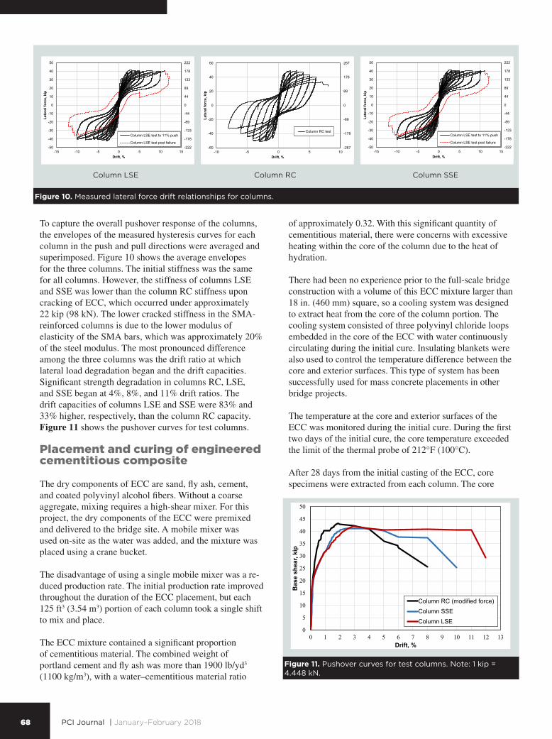
Lateral force drift relationships
Given different yield characteristics of steel-reinforced and SMA-reinforced members, the force drift ratio relationship of the column models was compared. Figure 10 shows the measured results. The hysteresis curves in all three columns were stable prior to failure. The relationship for column RC is considered satisfactory because it is similar to that expected from a reinforced concrete bridge column that meets the current seismic design standards. The response of columns LSE and SSE was flag shaped because it was controlled by the superelastic behavior of SMA bars. There was no strength degradation in column LSE until after a 10% drift ratio. Strength loss in column SSE occurred after 8% drift ratio.
sive strength of 5 ksi [34 MPa]), which matched that of the AWV-SAC bridge columns.
The lateral loading protocol for all of the test columns con-sisted of cyclic loads to different drift levels until failure as indicated by fracture of longitudinal bars and significant loss of the lateral load strength.
The average conventional concrete compressive strength measured on test days varied from 5.38 to 5.74 ksi (37.1 and 39.6 MPa). The compressive strength of ECC was 6.89 and 7.20 ksi (47.5 and 49.6 MPa) on the day of testing of columns LSE and SSE, respectively. The average measured yield stress for no. 4 (13M) and no. 5 (16M) steel rein-forcement was 71 and 65 ksi (490 and 450 MPa), respec-tively. The average effective yield stress of SMA bars was 54 ksi (370 MPa). More details about the test models are presented in Nakashoji and Saiidi.13
Test results: Apparent damage
Loading was paused at peak amplitude of each cycle, cracks were marked, photos of the plastic-hinge zone were taken, and the data were checked. As expected, there were differences in the apparent damage between column RC and the other two column models due to the use of ECC. Figure 9 shows the damage in the column models at 8% drift. Fracture of the longitudinal bars in column RC began under 6% drift ratio. More longitudinal bars
Figure 9. Damage on south side at 8% drift in columns.
Column RC Column LSE Column SSE
68 PCI Journal | January–February 2018
of approximately 0.32. With this significant quantity of cementitious material, there were concerns with excessive heating within the core of the column due to the heat of hydration.
There had been no experience prior to the full-scale bridge construction with a volume of this ECC mixture larger than 18 in. (460 mm) square, so a cooling system was designed to extract heat from the core of the column portion. The cooling system consisted of three polyvinyl chloride loops embedded in the core of the ECC with water continuously circulating during the initial cure. Insulating blankets were also used to control the temperature difference between the core and exterior surfaces. This type of system has been successfully used for mass concrete placements in other bridge projects.
The temperature at the core and exterior surfaces of the ECC was monitored during the initial cure. During the first two days of the initial cure, the core temperature exceeded the limit of the thermal probe of 212°F (100°C).
After 28 days from the initial casting of the ECC, core specimens were extracted from each column. The core
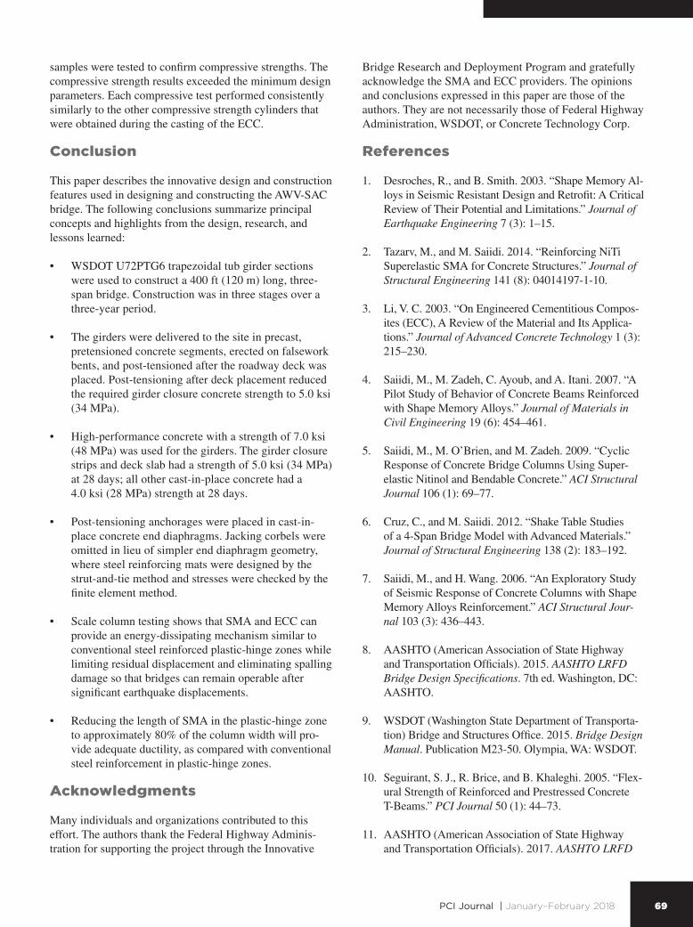
To capture the overall pushover response of the columns, the envelopes of the measured hysteresis curves for each column in the push and pull directions were averaged and superimposed. Figure 10 shows the average envelopes for the three columns. The initial stiffness was the same for all columns. However, the stiffness of columns LSE and SSE was lower than the column RC stiffness upon cracking of ECC, which occurred under approximately 22 kip (98 kN). The lower cracked stiffness in the SMA-reinforced columns is due to the lower modulus of elasticity of the SMA bars, which was approximately 20% of the steel modulus. The most pronounced difference among the three columns was the drift ratio at which lateral load degradation began and the drift capacities. Significant strength degradation in columns RC, LSE, and SSE began at 4%, 8%, and 11% drift ratios. The drift capacities of columns LSE and SSE were 83% and 33% higher, respectively, than the column RC capacity. Figure 11 shows the pushover curves for test columns.
Placement and curing of engineered cementitious composite
The dry components of ECC are sand, fly ash, cement, and coated polyvinyl alcohol fibers. Without a coarse aggregate, mixing requires a high-shear mixer. For this project, the dry components of the ECC were premixed and delivered to the bridge site. A mobile mixer was used on-site as the water was added, and the mixture was placed using a crane bucket.
The disadvantage of using a single mobile mixer was a re-duced production rate. The initial production rate improved throughout the duration of the ECC placement, but each 125 ft3 (3.54 m3) portion of each column took a single shift to mix and place.
The ECC mixture contained a significant proportion of cementitious material. The combined weight of portland cement and fly ash was more than 1900 lb/yd3 (1100 kg/m3), with a water–cementitious material ratio
Figure 11
0
5
10
15
20
25
30
35
40
45
50
0 1 2 3 4 5 6 7 8 9 10 11 12 13
Bas
e sh
ear,
kip
Drift, %
Column RC (modified force)Column SSEColumn LSE
Figure 11. Pushover curves for test columns. Note: 1 kip = 4.448 kN.
Figure 10. Measured lateral force drift relationships for columns.
-222
-178
-133
-89
-44
0
44
89
133
178
222
-50
-40
-30
-20
-10
0
10
20
30
40
50
-15 -10 -5 0 5 10 15
Late
ral f
orce
, kip
Drift, %
Column LSE test to 11% push
Column LSE test post failure
-267
-178
-89
0
89
178
267
-60
-40
-20
0
20
40
60
-10 -5 0 5 10
Late
ral f
orce
, kip
Drift, %
Column RC test
-222
-178
-133
-89
-44
0
44
89
133
178
222
-50
-40
-30
-20
-10
0
10
20
30
40
50
-15 -10 -5 0 5 10 15
Late
ral f
orce
, kip
Drift, %
Column LSE test to 11% push
Column LSE test post failure
-267
-178
-89
0
89
178
267
-60
-40
-20
0
20
40
60
-10 -5 0 5 10
Late
ral f
orce
, kip
Drift, %
Column RC test
-222
-178
-133
-89
-44
0
44
89
133
178
222
-50
-40
-30
-20
-10
0
10
20
30
40
50
-15 -10 -5 0 5 10 15
Late
ral f
orce
, kip
Drift, %
Column LSE test to 11% push
Column LSE test post failure
-267
-178
-89
0
89
178
267
-60
-40
-20
0
20
40
60
-10 -5 0 5 10
Late
ral f
orce
, kip
Drift, %
Column RC test
Column RCColumn LSE Column SSE
69PCI Journal | January–February 2018
Bridge Research and Deployment Program and gratefully acknowledge the SMA and ECC providers. The opinions and conclusions expressed in this paper are those of the authors. They are not necessarily those of Federal Highway Administration, WSDOT, or Concrete Technology Corp.
References
1. Desroches, R., and B. Smith. 2003. “Shape Memory Al-loys in Seismic Resistant Design and Retrofit: A Critical Review of Their Potential and Limitations.” Journal of Earthquake Engineering 7 (3): 1–15.
2. Tazarv, M., and M. Saiidi. 2014. “Reinforcing NiTi Superelastic SMA for Concrete Structures.” Journal of Structural Engineering 141 (8): 04014197-1-10.
3. Li, V. C. 2003. “On Engineered Cementitious Compos-ites (ECC), A Review of the Material and Its Applica-tions.” Journal of Advanced Concrete Technology 1 (3): 215–230.
4. Saiidi, M., M. Zadeh, C. Ayoub, and A. Itani. 2007. “A Pilot Study of Behavior of Concrete Beams Reinforced with Shape Memory Alloys.” Journal of Materials in Civil Engineering 19 (6): 454–461.
5. Saiidi, M., M. O’Brien, and M. Zadeh. 2009. “Cyclic Response of Concrete Bridge Columns Using Super-elastic Nitinol and Bendable Concrete.” ACI Structural Journal 106 (1): 69–77.
6. Cruz, C., and M. Saiidi. 2012. “Shake Table Studies of a 4-Span Bridge Model with Advanced Materials.” Journal of Structural Engineering 138 (2): 183–192.
7. Saiidi, M., and H. Wang. 2006. “An Exploratory Study of Seismic Response of Concrete Columns with Shape Memory Alloys Reinforcement.” ACI Structural Jour-nal 103 (3): 436–443.
8. AASHTO (American Association of State Highway and Transportation Officials). 2015. AASHTO LRFD Bridge Design Specifications. 7th ed. Washington, DC: AASHTO.
9. WSDOT (Washington State Department of Transporta-tion) Bridge and Structures Office. 2015. Bridge Design Manual. Publication M23-50. Olympia, WA: WSDOT.
10. Seguirant, S. J., R. Brice, and B. Khaleghi. 2005. “Flex-ural Strength of Reinforced and Prestressed Concrete T-Beams.” PCI Journal 50 (1): 44–73.
11. AASHTO (American Association of State Highway and Transportation Officials). 2017. AASHTO LRFD
samples were tested to confirm compressive strengths. The compressive strength results exceeded the minimum design parameters. Each compressive test performed consistently similarly to the other compressive strength cylinders that were obtained during the casting of the ECC.
Conclusion
This paper describes the innovative design and construction features used in designing and constructing the AWV-SAC bridge. The following conclusions summarize principal concepts and highlights from the design, research, and lessons learned:
• WSDOT U72PTG6 trapezoidal tub girder sections were used to construct a 400 ft (120 m) long, three-span bridge. Construction was in three stages over a three-year period.
• The girders were delivered to the site in precast, pretensioned concrete segments, erected on falsework bents, and post-tensioned after the roadway deck was placed. Post-tensioning after deck placement reduced the required girder closure concrete strength to 5.0 ksi (34 MPa).
• High-performance concrete with a strength of 7.0 ksi (48 MPa) was used for the girders. The girder closure strips and deck slab had a strength of 5.0 ksi (34 MPa) at 28 days; all other cast-in-place concrete had a 4.0 ksi (28 MPa) strength at 28 days.
• Post-tensioning anchorages were placed in cast-in-place concrete end diaphragms. Jacking corbels were omitted in lieu of simpler end diaphragm geometry, where steel reinforcing mats were designed by the strut-and-tie method and stresses were checked by the finite element method.
• Scale column testing shows that SMA and ECC can provide an energy-dissipating mechanism similar to conventional steel reinforced plastic-hinge zones while limiting residual displacement and eliminating spalling damage so that bridges can remain operable after significant earthquake displacements.
• Reducing the length of SMA in the plastic-hinge zone to approximately 80% of the column width will pro-vide adequate ductility, as compared with conventional steel reinforcement in plastic-hinge zones.
Acknowledgments
Many individuals and organizations contributed to this effort. The authors thank the Federal Highway Adminis-tration for supporting the project through the Innovative
70 PCI Journal | January–February 2018
'cif = specified compressive strength of concrete at
time of initial prestress
fpu
= tensile strength of prestressing steel
fpy
= yield strength of prestressing steel
k = wobble friction coefficient
K = span moment distribution factor
CGpoM = plastic hinge moment at the center of gravity of
the superstructure
Msei
= moment due to overstrength plastic moment capacity of the column and associated over-strength plastic shear, either within or outside the effective width
MSIDL
= moment due to superimposed dead loads
intgN = number of girders encompassed by the effective
width
Nps
= number of prestressing strands
μ = curvature friction coefficient
ϕ = flexural resistance factor = 1.0
Bridge Construction Specifications. 4th ed. Washing-ton, DC: AASHTO.
12. Tazarv, M., and M. Saiidi. 2015. “Low-Damage Pre-cast Columns for Accelerated Bridge Construction in High Seismic Zones.” Journal of Bridge Engineering 21 (3): 04015056-1-13.
13. Nakashoji, B., and M. Saiidi. 2014. “Seismic Per-formance of Square Nickel-Titanium Reinforced ECC Columns with Headed Couplers.” Report CCEER-14-05. Reno, NV: Center for Civil Engineer-ing Earthquake Research, Department of Civil and Environmental Engineering, University of Nevada.
Notation
Aps
= area of each extended strand
Beff
= effective width of strand
d = distance from top of deck slab to center of gravity of extended strands
Dc = diameter or width of column
Ds = depth of superstructure from top of column to
top of deck slab
'cf = compressive strength of concrete

71PCI Journal | January–February 2018
About the authors
Tom Baker, PE, is the state bridge and structures engineer for the Washington State Department of Transportation (WSDOT) Bridge and Structures Office in Tumwa-ter, Wash.
M. Saiid Saiidi, PhD, PE, is a professor of civil and environmental engineering and the director of the Center for Advanced Technology for Bridges and Infrastructure at the University of Nevada, Reno.
Brian Nakashoji, EIT, is a structural engineer at HW Lochner in Boise, Idaho.
Jed Bingle, PE, SE, is a senior bridge designer for the WSDOT Bridge and Structures Office in Tumwater.
Tim Moore, PE, SE, is the Mega Projects Engineer for the WSDOT Bridge and Structures Office in Tumwater.
Bijan Khaleghi, PhD, PE, SE, is the state bridge design engineer for the WSDOT Bridge and Structures Office in Tumwater.
Abstract
An innovative bridge design was implemented for the reconstruction of the SR 99 Alaskan Way Viaduct south access connection bridge, a 400 ft (120 m) long, 30.5 ft (9.30 m) wide, three-span, precast, post-ten-sioned concrete spliced tub girder bridge in Seattle, Wash. The bridge’s superstructure consists of one 180 ft (55 m) long interior span and two 110 ft (34 m) long end spans. The bridge’s superstructure consists of Washington State Department of Transportation standard trapezoidal tub girder section U72PTG6. These precast concrete girder sections were trans-ported to the site in pieces, where they were spliced on temporary supports to produce a three-span, 400 ft long bridge. High-performance/high-strength concrete with design compressive strengths of 7.0 ksi (48 MPa) was specified for the precast concrete segments. The bridge substructure consists of two intermediate piers using shape-memory alloy (SMA) along with engi-neered cementitious composite (ECC) in plastic-hinge zones of the columns. The focus of this paper is the experimental and analytical studies that were under-taken to evaluate and optimize SMA ECC columns for the bridge and to describe key aspects of the precast concrete spliced bridge design and implementation of SMA and ECC into the bridge.
Keywords
Bridge, ECC, engineered cementitious composite, seis-mic design, shape-memory alloy, SMA, spliced girder, superelastic.
Review policy
This paper was reviewed in accordance with the Precast/Prestressed Concrete Institute’s peer-review process.
Reader comments
Please address reader comments to [email protected] or Precast/Prestressed Concrete Institute, c/o PCI Journal, 200 W. Adams St., Suite 2100, Chicago, IL 60606. J


![Welcome [sd44bridge.com] · Spliced Precast Concrete Girder—Constant Depth Virtual rendering of a variable depth spliced precast ... The Four Bears Bridge in North Dakota is an](https://img.pdfslide.net/doc/110x75/5fe6a8cb1e8b9839ab5ab9ee/welcome-spliced-precast-concrete-girderaconstant-depth-virtual-rendering-of.jpg)