Embed Size (px)
Citation preview
NEW TECHNOLOGY
Precast, Prestressed Pedestrian Bridge World's First Reactive Powder Concrete Structure
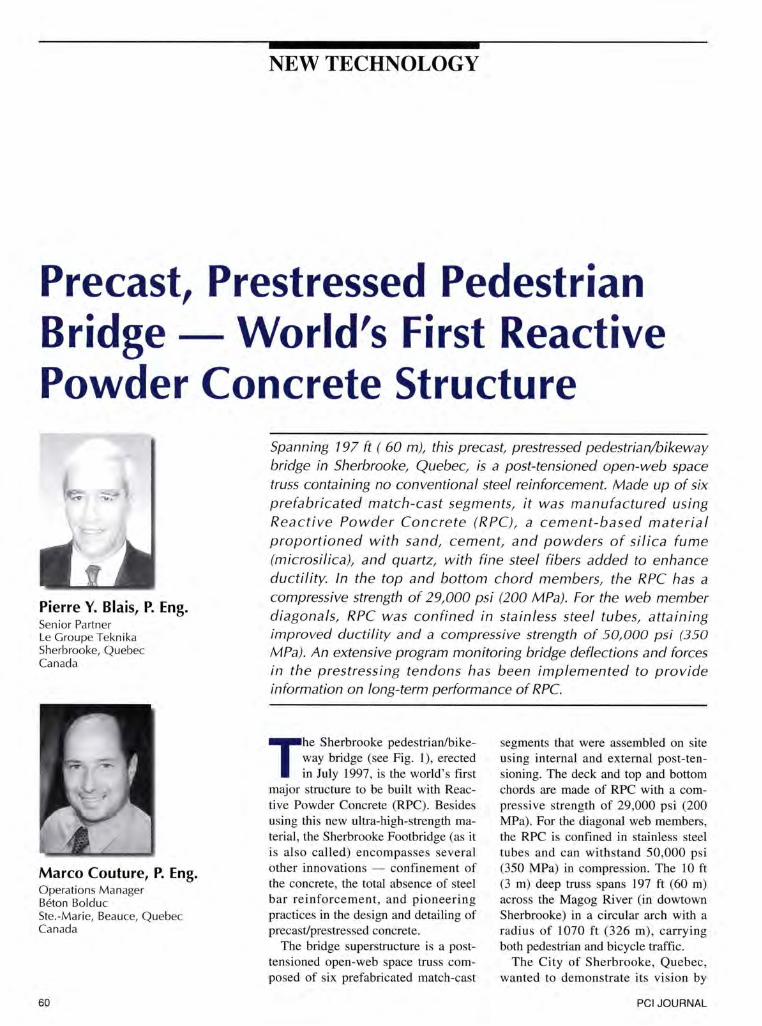
Pierre Y. Blais, P. Eng. Senior Partner Le Groupe Teknika Sherbrooke, Quebec Canada
Marco Couture, P. Eng. Operations Manager Beton Bolduc Ste.-Marie, Beauce, Quebec Canada
60
Spanning 7 97 ft ( 60 m), this precast prestressed pedestrian/bikeway bridge in Sherbrooke, Quebec, is a post-tensioned open-web space truss containing no conventional steel reinforcement. Made up of six prefabricated match-cast segments, it was manufactured using Reactive Powder Concrete (RPC), a cement-based material proportioned with sand, cement, and powders of silica fume (microsilica), and quartz, with fine steel fibers added to enhance ductility. In the top and bottom chord members, the RPC has a compressive strength of 29,000 psi (200 MPa). For the web member diagonals, RPC was confined in stainless steel tubes, attaining improved ductility and a compressive strength of 50, 000 psi (350
MPa). An extensive program monitoring bridge deflections and forces in the prestressing tendons has been implemented to provide information on long-term performance of RPC.
The Sherbrooke pedestrian/bikeway bridge (see Fig. 1), erected in July 1997, is the world's first
major structure to be built with Reactive Powder Concrete (RPC). Besides using this new ultra-high-strength material , the Sherbrooke Footbridge (as it is also called) encompasses several other innovations - confinement of the concrete, the total absence of steel bar reinforcement, and pioneering practices in the design and detailing of precast/prestressed concrete.
The bridge superstructure is a posttensioned open-web space truss composed of six prefabricated match-cast
segments that were assembled on site using internal and external post-tensioning. The deck and top and bottom chords are made of RPC with a compressive strength of 29,000 psi (200 MPa). For the diagonal web members, the RPC is confined in stainless steel tubes and can withstand 50,000 psi (350 MPa) in compression. The 10 ft (3 m) deep truss spans 197 ft (60 m) across the Magog River (in dowtown Sherbrooke) in a circular arch with a radius of 1070 ft (326 m) , carrying both pedestrian and bicycle traffic.
The City of Sherbrooke, Quebec, wanted to demonstrate its vision by
PCI JOURNAL
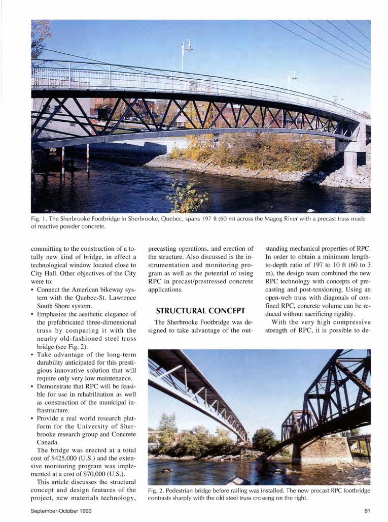
Fig. 1. The Sherbrooke Footbridge in Sherbrooke, Quebec, spans 197ft (60 m) across the Magog River with a precast truss made of reactive powder concrete.
committing to the construction of a totally new kind of bridge, in effect a technological window located close to City Hall. Other objectives of the City were to: • Connect the American bikeway sys
tem with the Quebec-St. Lawrence South Shore system.
• Emphasize the aesthetic elegance of the prefabricated three-dimensional truss by comparing it with the nearby old-fashioned steel truss bridge (see Fig. 2).
• Take advantage of the long-term durability anticipated for this prestigious innovative solution that will require only very low maintenance.
• Demonstrate that RPC will be feasible for use in rehabilitation as well as construction of the municipal infrastructure.
• Provide a real world research platform for the University of Sherbrooke research group and Concrete Canada. The bridge was erected at a total
cost of $425 ,000 (U.S.) and the extensive monitoring program was implemented at a cost of $70,000 (U.S.) .
This article discusses the structural concept and design features of the project , new materials technology ,
September-October 1999
precasting operations, and erection of the structure. Also discussed is the instrumentation and monitoring program as well as the potential of using RPC in precast/prestressed concrete applications.
STRUCTURAL CONCEPT The Sherbrooke Footbridge was de
signed to take advantage of the out-
standing mechanical properties of RPC. In order to obtain a minimum lengthto-depth ratio of 197 to 10 ft ( 60 to 3 m), the design team combined the new RPC technology with concepts of precasting and post-tensioning. Using an open-web truss with diagonals of confined RPC, concrete volume can be reduced without saclificing rigidity.
With the very high compressive strength of RPC, it is possible to de-
Fig. 2. Pedestrian bridge before railing was insta lled. The new precast RPC footbridge contrasts sharply with the old steel truss crossing on the right.
61
()) 1\)
----------, I
0 __ !.!!909
MAGOG RIVER
PLAN
•' .·
FRONTENAC STREET
I ' ' ' '
' ' ' '
/o---
10000 15000 -· -·-·---- ------~~----------------------·---~----~1~0000~-----i --~----29867
WALlNOJNORTH 1 PIER N0,2NORTH 1 PIER N0.1 NORTH
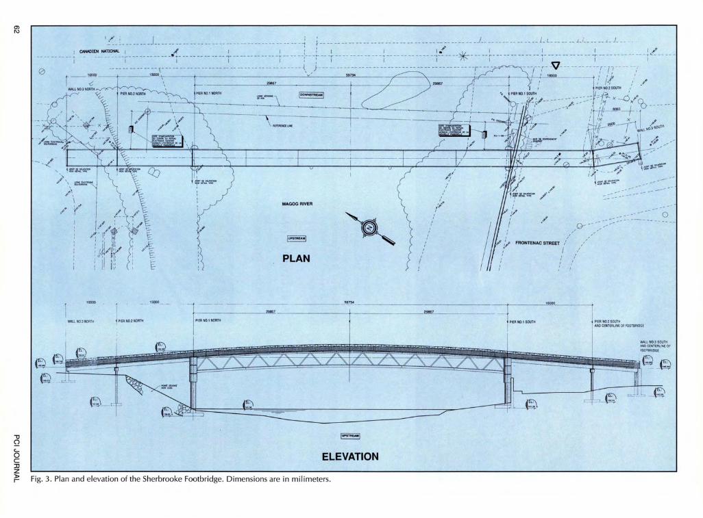
c.... ~ ELEVATION JJ z f:. Fig. 3. Plan and elevation of the Sherbrooke Footbridge. Dimensions are in milimeters.
29867
PIER N0.1 SOUTH
0
PIER N0.2 SOUTH ANO CE NTERLINE OF FOOT BAIOGE
sign a relatively lightweight prestressed structure, have it plant fabricated and assembled on site.
To bridge users, there is also the added benefit of enhanced comfort due to low vibration. Because the truss is lightweight and has high overall rigidity, the structure exhibits a first Eigen frequency of 2.5 Hz, even though the live load is within the range of the dead load. '
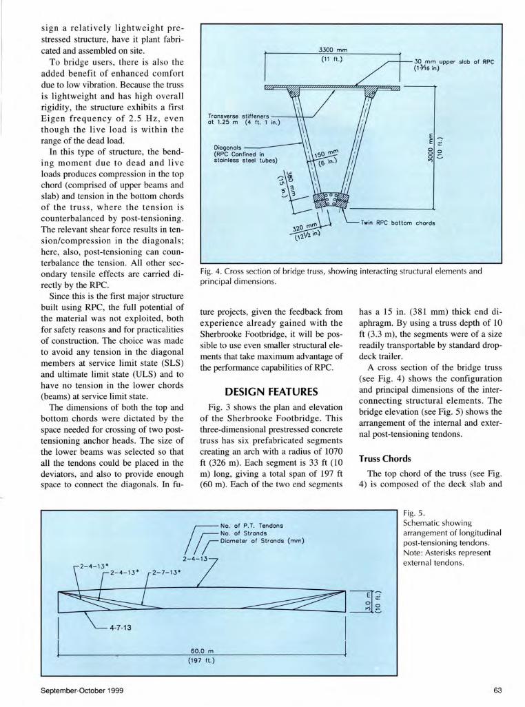
Oiogonols ---\ (RPC Confined in ' stainless steel tubes)
3300 mm
(11 ft.) ~--r-30 mm upper slob of RPC (1-¥16 in)
Twin RPC bottom chords
In this type of structure, the bending moment due to dead and live loads produces compression in the top chord (comprised of upper beams and slab) and tension in the bottom chords of the truss, where the tension is counterbalanced by post-tensioning. The relevant shear force results in tension/compression in the diagonal s; here, also, post-tensioning can counterbalance the tension. All other secondary tensile effects are carried directly by the RPC.
Fig. 4. Cross section of bridge truss, showing interacting structura l elements and principal dimensions.
Since this is the first major structure built using RPC, the full potential of the material was not exploited, both for safety reasons and for practicalities of construction. The choice was made to avoid any tension in the diagonal members at service limit state (SLS) and ultimate limit state (ULS) and to have no tension in the lower chords (beams) at service limit state.
The dimensions of both the top and bottom chords were dictated by the space needed for crossing of two posttensioning anchor heads. The size of the lower beams was selected so that all the tendons could be placed in the deviators, and also to provide enough space to connect the diagonals. In fu-
ture projects, given the feedback from experience already gained with the Sherbrooke Footbridge, it will be possible to use even smaller structural elements that take maximum advantage of the performance capabilities of RPC.
DESIGN FEATURES Fig. 3 shows the plan and elevation
of the Sherbrooke Footbridge. This three-dimensional prestressed concrete truss has six prefabricated segments creating an arch with a radius of 1070 ft (326 m). Each segment is 33 ft (10 m) long, giving a total span of 197 ft (60 m). Each of the two end segments
& No. of P. T. Tendons No. of Strands Diameter of Strands (mm)
2-4-13
4-7-13
60.0 m
(197 ft.)
September-October 1999
has a 15 in . (381 mm) thick end diaphragm. By using a truss depth of 10 ft (3.3 m) , the segments were of a size readily transportable by standard dropdeck trailer.
A cross section of the bridge truss (see Fig. 4) shows the configuration and principal dimensions of the interconnecting structural elements. The bridge elevation (see Fig. 5) shows the arrangement of the internal and external post-tensioning tendons.
Truss Chords
The top chord of the truss (see Fig. 4) is composed of the deck slab and
Fig. 5. Schematic showing arrangement of longitudinal post-tensioning tendons. Note: Asterisks represent external tendons.
63
transverse stiffening elements embedded into two longitudinal ribs that are 8 x 12 in. (200 x 300 mm) in cross section. The deck must support an 81 psf (3.9 kN/m2) live load, and deicing and snow removal equipment weighing 2.9 tons (2.6 tonnes).
The deck was designed as being embedded in the top beams and able to withstand a flexural tensile stress of 1740 psi (12 MPa) at ULS. This constraint defined the amount of transverse prestressing to be applied, i.e., one 1/ 2 in. (12 mm) greasedsheathed monostrand every 4 ft 1 in. (1.25 m). Note that shear and punching force was resisted directly by the RPC.
The deck slab is 131!6 in. (30 mm) thick and 11 ft (3.3 m) wide. The transverse monostrands were placed in 23/4 in. (70 mm) deep stiffening ribs embedded in the longitudinal ribs. Although not required for load capacity, internal prestressing was placed in these upper longitudinal members to fully tighten the structure. The transverse stiffening ribs are 4 in. (100 mm) wide, spaced 4 ft 1 in. (1.25 m) on center. There are also continuous ribs of the same thickness along the two edges of the slab.
The truss (see Fig. 4) has two bottom chords, each 12'12 x 15 in. (320 x 380 mm), with struts every 16 ft 5 in. (5 m) corresponding to the connections between the web members and the bottom beams. These struts are used to join the two parallel beams and act as deviators for the external
Mini Anchorage
longitudinal post-tensioning tendons. Note that internal tendons were installed in these lower beams to provide continuity between the segments and to avoid any tensile stress in these beams at SLS.
Truss Diagonals
The truss diagonals, which slope in two directions, are made of RPC confined in 6 in. (150 mm) diameter stainless steel tubes with a wall thickness of 1h6 in. (2 mm). These diagonals are 10112 ft (3.2 m) long, and inclined in two directions , i.e. , at 41 degrees to the longitudinal direction and 14 degrees to the transverse direction of the structure. Each of the six bridge segments contains four web members in each of the sloping planes.
Space considerations limited the number of prestressing strands in each diagonal to two; that would provide a compressive force of 2 x 117 .4 = 235.4 kN (53 kips) after prestress losses. Because the shear force induced in the first four diagonals by dead and live load at ULS exceeded this level, it was necessary to reduce it by the effect of deviated prestressing. The stressing force of the 2 x 3 external tendons (three asterisked tendons shown in Fig. 5) was adjusted to achieve this goal.
The two greased-sheathed monostrands in each diagonal are anchored in custom-designed miniaturized anchors. These anchors, developed specially for this project, are fully
_...,.. ~ -~ ~ <0
o;:;;:: --------------T-~~~~~---------n~~
Mini Anchorage
encapsulated and have neither a bearing plate nor local zone spirals. The anchor head is in direct contact with the RPC, which can withstand the high compressive stresses beneath the anchor head.
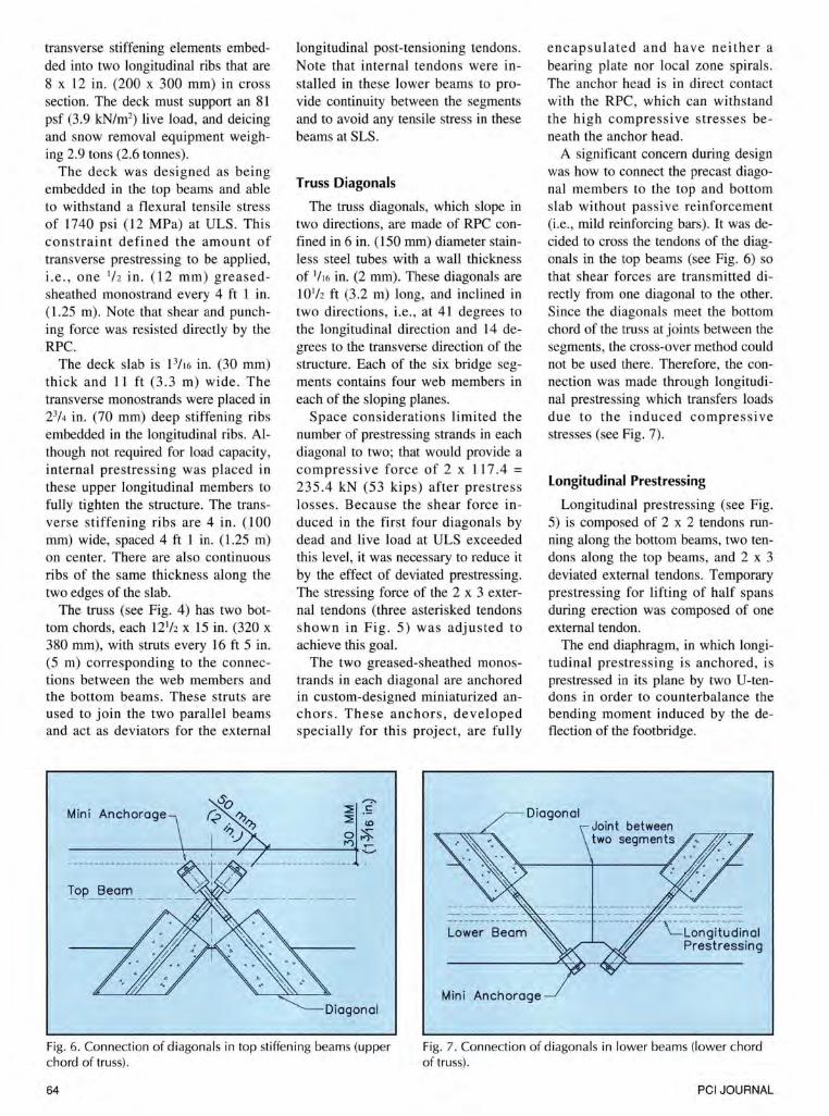
A significant concern during design was how to connect the precast diagonal members to the top and bottom slab without passive reinforcement (i.e., mild reinforcing bars). It was decided to cross the tendons of the diagonals in the top beams (see Fig. 6) so that shear forces are transmitted directly from one diagonal to the other. Since the diagonals meet the bottom chord of the truss at joints between the segments, the cross-over method could not be used there. Therefore, the connection was made through longitudinal prestressing which transfers loads due to the induced compressive stresses (see Fig. 7).
Longitudinal Prestressing
Longitudinal prestressing (see Fig. 5) is composed of 2 x 2 tendons running along the bottom beams, two tendons along the top beams, and 2 x 3 deviated external tendons. Temporary prestressing for lifting of half spans during erection was composed of one external tendon.
The end diaphragm, in which longitudinal prestressing is anchored, is prestressed in its plane by two U-tendons in order to counterbalance the bending moment induced by the deflection of the footbridge.
Fig. 6. Connection of diagonals in top stiffening beams (upper chord of truss).
Fig. 7. Connection of diagonals in lower beams (lower chord of truss) .
64 PCI JOURNAL
MATERIALS USED IN BRIDGE
The Sherbrooke Footbridge is made entirely of RPC, both confined and unconfined, containing fine steel fibers. RPC is a new type of cement-based material proportioned with powders whose particle sizes range from about 24 mil (0.024 in. or 0.6 mm) to less than 0 .004 mil (0.0001 mm) . The grain size distribution of the various powders - portland cement, silica fume, ground quartz, and sand - is optimized to obtain maximum compactness.
Portland cement, silica fume, ground quartz and to a much lesser extent sand react chemically during the various processing stages in forming the material. Heating RPC for two days in a vapor-saturated atmosphere at 195°F (90°C), once setting has occurred, accelerates the pozzolanic reaction of the silica fume and modifies the structure of the hydrate. Heat treatment increases the strength.
Further information on the Sherbrooke Footbridge and the role that RPC played are given in Refs . 1 through 5.
The term "concrete" is used rather than "mortar" to describe RPC because of the mechanical behavior of RPC when fine steel fibers are added for enhanced ductility . Considering the scale effect helps to understand the significance of these fibers. If RPC, whose maximum particle size is 0.024 in. (0.6 mm) , is compared to concrete made with 1 in. (25 mm) maximum coarse aggregate, the scale is 1 in. to 0.024 in . (25 mm to 0 .6 mm), or 42 to 1. Adding a steel fiber that measures 0.008 x 1 in. (0.2 x 25 mm) to the RPC is like adding a 5!1 6
in. x 3 ft 3 in. (8 mm x 1 m) reinforcing bar to ordinary reinforced concrete made with the 1 in. (25 mm) coarse aggregate.
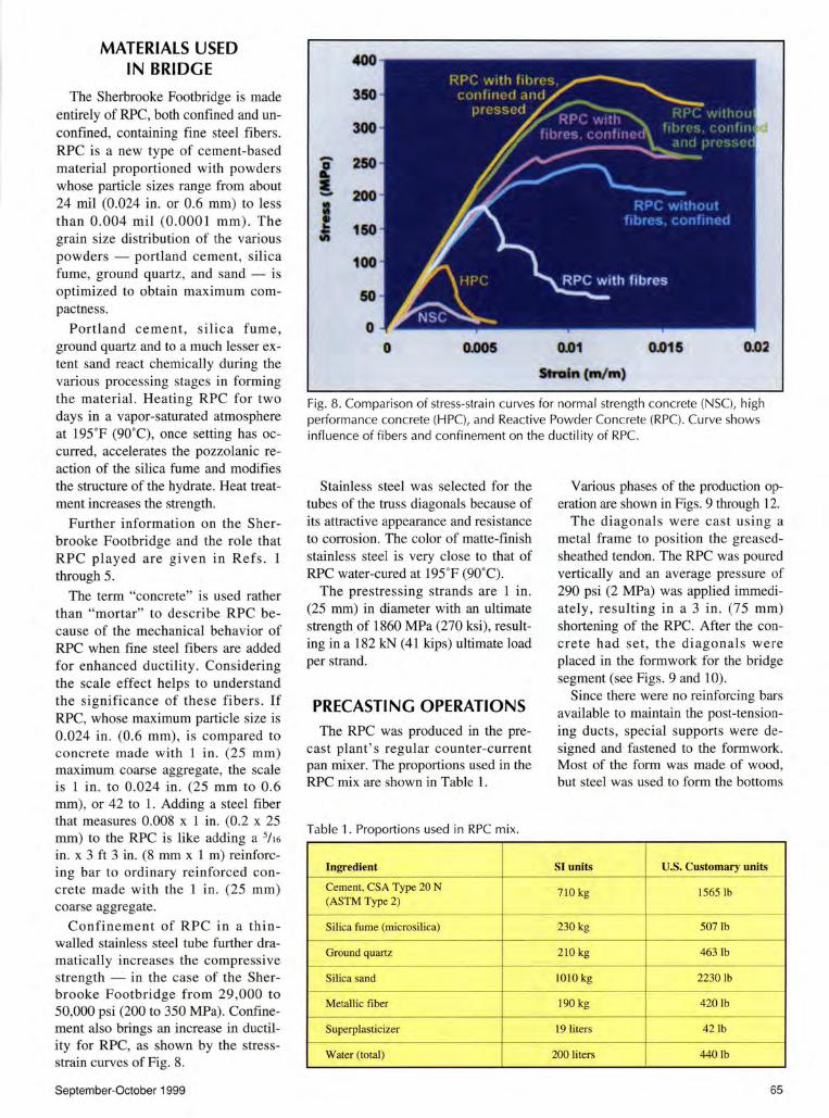
Confinement of RPC in a thin walled stainless steel tube further dramatically increases the compressive strength - in the case of the Sherbrooke Footbridge from 29,000 to 50,000 psi (200 to 350 MPa). Confinement also brings an increase in ductility for RPC, as shown by the stressstrain curves of Fig. 8.
September-October 1999
400
350
300
' 250
200 -I 150
100
50
0 0 0.005 0.01 0.015 0.02
Stfoln (m/m)
Fig. 8. Comparison of stress-strain curves for normal strength concrete (NSC), high performance concrete (HPC), and Reactive Powder Concrete (RPC). Curve shows influence of fibers and confinement on the ductility of RPC.
Stainless steel was selected for the tubes of the truss diagonals because of its attractive appearance and resistance to corrosion. The color of matte-finish stainless steel is very close to that of RPC water-cured at 195"F (90°C).
The prestressing strands are 1 in . (25 mm) in diameter with an ultimate strength of 1860 MPa (270 ksi), resulting in a 182 kN (41 kips) ultimate load per strand.
PRECASTING OPERATIONS
The RPC was produced in the precast plant 's regular counter-current pan mixer. The proportions used in the RPC mix are shown in Table 1.
Table 1. Proportions used in RPC mix.
Ingredient
Cement. CSA Type 20 N (ASTM Type 2)
Si lica fume (microsilica)
Ground quartz
Silica sand
Metallic fi ber
Superplasticizer
Water (total)
Various phases of the production operation are shown in Figs. 9 through 12.
The diagonals were cast using a metal frame to position the greasedsheathed tendon. The RPC was poured vertically and an average pressure of 290 psi (2 MPa) was applied immediately, resulting in a 3 in. (75 mm) shortening of the RPC. After the concrete had set, the diagonals were placed in the forrnwork for the bridge segment (see Figs. 9 and 10).
Since there were no reinforcing bars available to maintain the post-tensioning ducts, special supports were designed and fastened to the formwork. Most of the form was made of wood, but steel was used to form the bottoms
SI units U.S. Customary units
7 10 kg 1565 lb
230 kg 507lb
210 kg 463 lb
IO!O kg 2230lb
190 kg 4201b
19 liters 42lb
200 liters 440lb
65
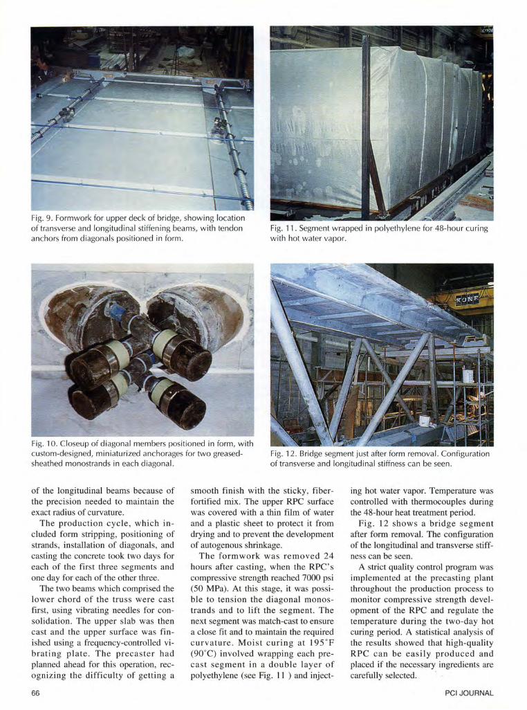
Fig. 9. Formwork for upper deck of bridge, showing location of transverse and longitudinal stiffening beams, with tendon anchors from diagonals positioned in form.
Fig. 11 . Segment wrapped in polyethylene for 48-hour curing with hot water vapor.
Fig. 10. Closeup of diagonal members positioned in form, with custom-designed, miniaturized anchorages for two greasedsheathed monostrands in each diagonal.
Fig. 12. Bridge segment just after form removal. Configuration of transverse and longitudinal stiffness can be seen.
of the longitudinal beams because of the precision needed to maintain the exact radius of curvature.
The production cycle, which included form stripping, positioning of strands, installation of diagonals , and casting the concrete took two days for each of the first three segments and one day for each of the other three.
The two beams which comprised the lower chord of the truss were cast first, using vibrating needles for consolidation. The upper slab was then cast and the upper surface was finished using a frequency-controlled vibrating plate. The precaster had planned ahead for this operation, recognizing the difficulty of getting a
66
smooth finish with the sticky, fiberfortified mix. The upper RPC surface was covered with a thin film of water and a plastic sheet to protect it from drying and to prevent the development of autogenous shrinkage.
The formwork was removed 24 hours after casting, when the RPC's compressive strength reached 7000 psi (50 MPa). At this stage, it was possible to tension the diagonal monostrands and to lift the segment. The next segment was match-cast to ensure a close fit and to maintain the required curvature. Moist curing at 195 ' F (90' C) involved wrapping each precast segment in a double layer of polyethylene (see Fig. 11 ) and inject-
ing hot water vapor. Temperature was controlled with thermocouples during the 48-hour heat treatment period.
Fig . 12 shows a bridge segment after form removal. The configuration of the longitudinal and transverse stiffness can be seen.
A strict quality control program was implemented at the precasting plant throughout the production process to monitor compressive strength development of the RPC and regulate the temperature during the two-day hot curing period. A statistical analysis of the results showed that high-quality RPC can be easily produced and placed if the necessary ingredients are carefully selected. ·
PCI JOURNAL
It was fairly easy to obtain the powders required to produce the RPC for this project (especially the cement and silica fume) and to optimize their composition to meet the very stringent requirements for mechanical strength. The quality control program also showed that it is possible to consistently produce RPC with specific properties throughout the fabrication process.
Plant precasting ensured the high quality control and efficient production of the structural elements. Moreover, production was carried out during the winter so that the precast components would be ready for shipment and immediate installation as soon as the weather permitted.
ASSEMBLY AND ERECTION
Because of the lightweight design, the three plant-cast elements comprising half of the superstructure weighed only 55 tons (50 tonnes). This permitted the use of ordinary 100 and 165 ton (91 and 150 tonnes) cranes, which reduced on-site erection time to less than four days .
The superstructure erection procedure included the following steps: • A rock platform was constructed
across one half of the riverbed. • A temporary falsework bent was set
up in the river at midspan. • Three truss segments (see Figs. 13
and 14), i.e. , half of the superstructure, were set up on falsework and post-tensioned together using temporary tendons.
• The three-segment 98 1/z ft (30 m) long half span was set on the north pier and the falsework at midspan (see Fig. 15).
• The south half of the span was assembled and set in place in a sirilllar manner (see Fig. 16).
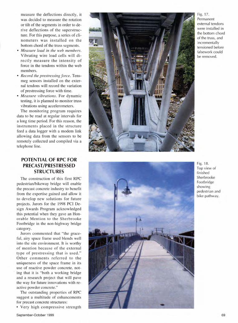
• Permanent external tendons were installed (see Fig. 17) and incrementally tensioned.
• The falsework was then dismantled. • Safety barriers were placed, and
lighting installed. The deck topping applied in the precaster's plant covered all the fine steel fibers exposed at the surface. Completed views of the Sher
brooke Footbridge are shown in Figs. 18 and 19.
September-October 1999
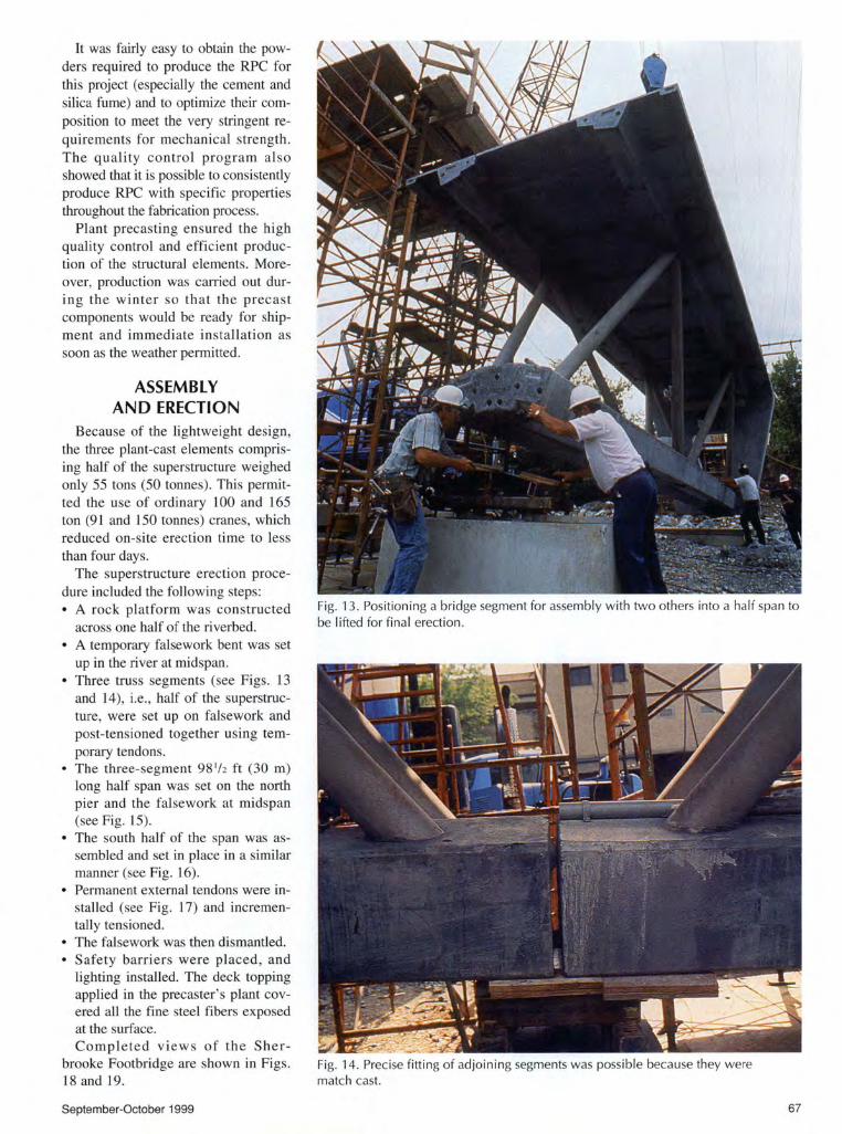
Fig. 13. Positioning a bridge segment for assembly with two others into a half span to be lifted for final erection.
Fig. 14. Precise fitting of adjoining segments was possible because they were match cast.
67
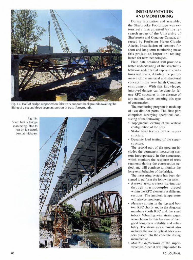
Fig. 15. Half of bridge supported on falsework support (background) awaiting the l ifting of a second three-segment portion of truss (foreground).
Fig. 16. South half of bridge span being lifted to
rest on fa lsework bent at midspan.
68
INSTRUMENTATION AND MONITORING
During fabrication and assembly, the Sherbrooke Footbridge was extensively instrumented by the research group of the University of Sherbrooke and Concrete Canada, directed by Professor Pierre-Claude Ai'tcin. Installation of sensors for short and long-term monitoring make this project an important testing bench for new technologies.
Field data obtained will provide a better understanding of the structure's behavior under actual exposure conditions and loads, detailing the performance of the material and structural concept in the very harsh Canadian environment. With this knowledge, improved designs can be done for future RPC structures in the absence of any national codes covering this type of construction.
The monitoring program is made up of two distinct parts. The first part comprises surveying operations consisting of the following: • Topographic leveling of the vertical
configuration of the deck. • Static load testing of the super
structure. • Dynamic load testing of the super
structure. The second part of the program in
cludes the permanent measuring system incorporated in the structure, which monitors the response of truss segments during the construction period, and will continue to monitor the long-term behavior of the bridge.
The measuring system has been designed to perform the following tasks: • Record temperature variations
through thermocouples placed within the RPC elements at different sections. The ambient temperature will also be monitored.
• Measure strains in the top and bottom RPC chords and in the diagonal members (both RPC and the steel tubes). Vibrating wire strain gages were chosen for this because of their good long-term stability and reliability. The strain measurement also includes the use of optical fiber sensors placed into the concrete during manufacture.
• Monitor deflections of the superstructure. Since it was impossible to
PCI JOURNAL
measure the deflections directly, it was decided to measure the rotation or tilt of the segments in order to derive deflections of the superstructure. For this purpose, a series of clinometers was installed on the bottom chord of the truss segments.
• Measure load in the web members. Vibrating wire load cells will directly measure the intensity of force in the tendons within the web members.
• Record the prestressing force. Tensmeg sensors installed on the external tendons will record the variation of prestressing force with time.
• Measure vibrations. For dynamic testing, it is planned to monitor truss vibrations using accelerometers . The monitoring program requires
data to be read at regular intervals for a long time period. For this reason, the instruments placed in the structure feed a data logger with a modem link allowing data from the sensors to be remotely collected and compiled via a telephone line.
POTENTIAL OF RPC FOR PRECAST /PRESTRESSED
STRUCTURES The construction of this first RPC
pedestrian/bikeway bridge will enable the precast concrete industry to benefit from the expertise gained and allow it to develop new solutions for future projects. Jurors for the 1998 PCI Design Awards Program acknowledged this potential when they gave an Honorable Mention to the Sherbrooke Footbridge in the non-highway bridge category.
Jurors commented that "the graceful, airy space frame used blends well into the site environment. It is worthy of mention because of the external type of prestressing that is used." Other comments referred to the uniqueness of the space frame in its use of reactive powder concrete, noting that it is "both a working bridge and a research project that will pave the way for future innovations with reactive powder concrete."
The outstanding properties of RPC suggest a multitude of enhancements for precast concrete structures: • Very high compressive strength
September-October 1999
Fig. 17. Permanent external tendons were installed in the bottom chord of the truss, and incrementally tensioned before fa lsework cou ld be removed.
Fig. 18. Top view of finished Sherbrooke Footbridge showing pedestrian and bike pathway.
69
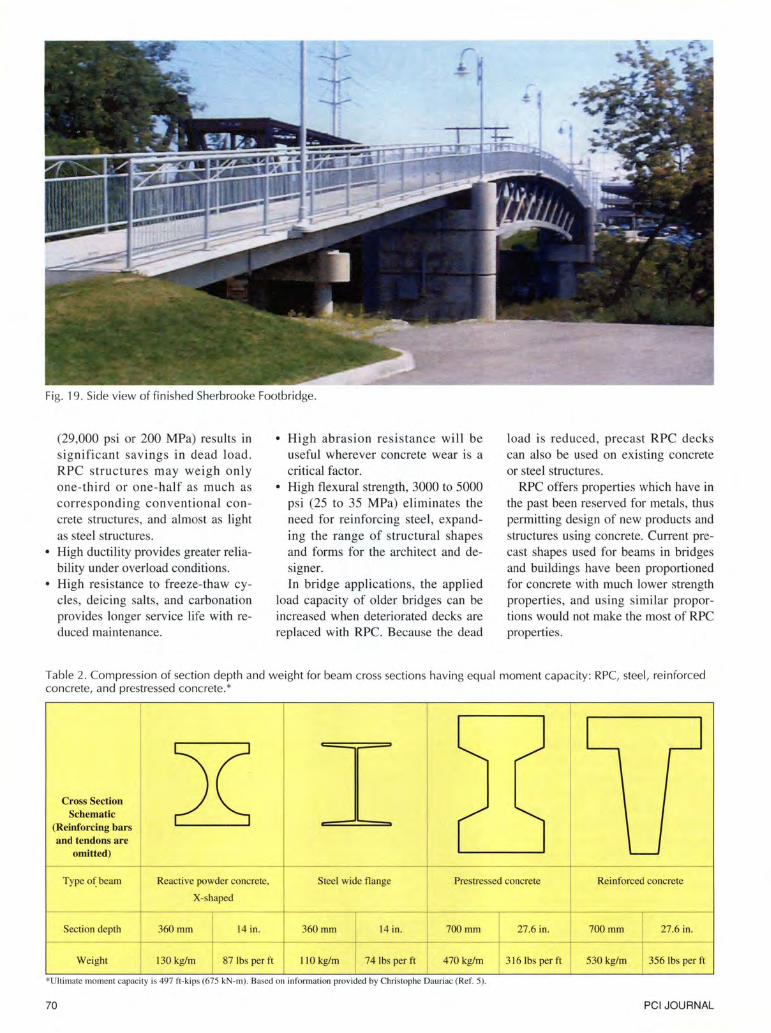
Fig. 19. Side view of finished Sherbrooke Footbridge.
(29,000 psi or 200 MPa) results in significant savings in dead load. RPC structures may weigh only one-third or one-half as much as corresponding conventional concrete structures, and almost as light as steel structures.
• High ductility provides greater reliability under overload conditions.
• High resistance to freeze-thaw cycles, deicing salts, and carbonation provides longer service life with reduced maintenance.
• High abrasion resistance will be useful wherever concrete wear is a critical factor.
• High flexural strength, 3000 to 5000 psi (25 to 35 MPa) eliminates the need for reinforcing steel, expanding the range of structural shapes and forms for the architect and designer. In bridge applications, the applied
load capacity of older bridges can be increased when deteriorated decks are replaced with RPC. Because the dead
load is reduced, precast RPC decks can also be used on existing concrete or steel structures.
RPC offers properties which have in the past been reserved for metals, thus permitting design of new products and structures using concrete. Current precast shapes used for beams in bridges and buildings have been proportioned for concrete with much lower strength properties, and using similar proportions would not make the most of RPC properties.
Table 2. Compression of section depth and weight for beam cross sections having equal moment capacity: RPC, steel , reinforced concrete, and prestressed concrete. *
Cross Section Schematic
(Reinforcing bars and tendons are
omitted)
Type o~beam
Section depth
Weight
Reactive powder concrete.
X-shaped
360mm 14 in.
130 kg/m 87 lbs per ft
Steel wide flange
360mm --+
110 kg/m
14 in.
74 lbs per fl
Prestressed concrete
_L 700mm 27 .6 in.
470 kg/m 3 16 lbs per ft
*Ultimate moment capacity is 497 ft-kips (675 kN-m). Based on information provided by Christophe Dauriac (Ref. 5).
70
Reinforced concrete
~ 700mm 27.6 in.
I 530 kg/m I 356 lbs per ft
PCI JOURNAL
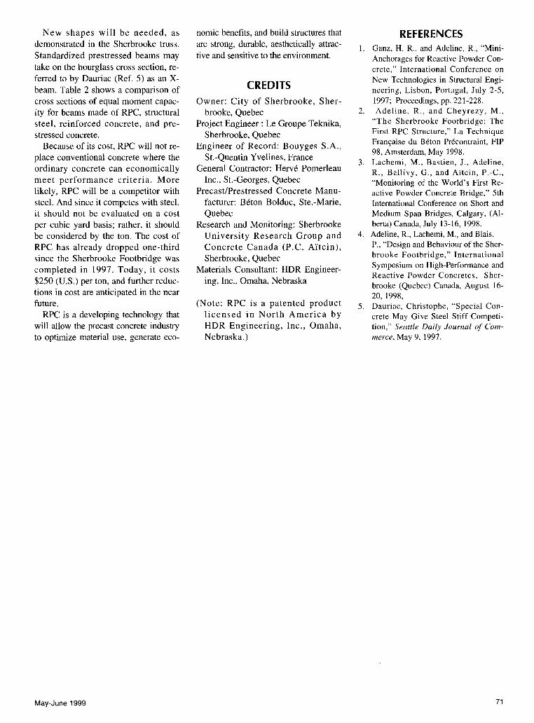
New shapes will be needed, as nomic benefits, and build structures that REFERENCES demonstrated in the Sherbrooke truss. are strong, durable, aesthetically attrac- 1. Ganz, H. R., and Adeline, R., "Mini-Standardized prestressed beams may tive and sensitive to the environment. Anchorages for Reactive Powder Con-take on the hourglass cross section, re- crete," International Conference on ferred to by Dauriac (Ref. 5) as an X-
CREDITS New Technologies in Structural Engi-
beam. Table 2 shows a comparison of neering, Lisbon, Portugal, July 2-5, cross sections of equal moment capac- Owner: City of Sherbrooke, Sher- 1997; Proceedings, pp. 221-228. ity for beams made of RPC, structural brooke, Quebec 2. Adeline, R., and Cheyrezy, M.,
steel, reinforced concrete, and pre- Project Engineer : Le Groupe Teknika, "The Sherbrooke Footbridge: The
stressed concrete. Sherbrooke, Quebec First RPC Structure," La Technique
Because of its cost, RPC will not re- Engineer of Record: Bouyges S.A., Fran9aise du Beton Precontraint, FIP
place conventional concrete where the St.-Quentin Yvelines, France 98, Amsterdam, May 1998.
3. Lachemi, M., Bastien, J., Adeline, ordinary concrete can economically General Contractor: Herve Pomerleau R., Ballivy, G., and Ai'tcin, P.-C., meet performance criteria. More Inc., St.-Georges, Quebec "Monitoring of the World's First Re-likely, RPC will be a competitor with Precast/Prestressed Concrete Manu- active Powder Concrete Bridge," 5th steel. And since it competes with steel, facturer: Beton Bolduc, Ste.-Marie, International Conference on Short and it should not be evaluated on a cost Quebec Medium Span Bridges, Calgary, (AI-per cubic yard basis; rather, it should Research and Monitoring: Sherbrooke berta) Canada, July 13-16, 1998.
be considered by the ton. The cost of University Research Group and 4. Adeline, R., Lachemi, M., and Blais,
RPC has already dropped one-third Concrete Canada (P.C. Aitcin), P., "Design and Behaviour of the Sher-
since the Sherbrooke Footbridge was Sherbrooke, Quebec brooke Footbridge," International
completed in 1997. Today, it costs Materials Consultant: HDR Engineer- Symposium on High-Performance and Reactive Powder Concretes, Sher-
$250 (U.S.) per ton, and further reduc- ing, Inc., Omaha, Nebraska brooke (Quebec) Canada, August 16-tions in cost are anticipated in the near 20, 1998, future. (Note: RPC is a patented product 5. Dauriac, Christophe, "Special Con-
RPC is a developing technology that licensed in North America by crete May Give Steel Stiff Competi-will allow the precast concrete industry HDR Engineering, Inc., Omaha, tion," Seattle Daily Journal of Com-to optimize material use, generate eco- Nebraska.) merce, May 9, 1997.
May-June 1999 71