Embed Size (px)
Citation preview
CONTENTS
PRECAUTIONS BEFORE STARTING OPERATION ------------------------------------- 1
PREPARATION FOR OPERATION
1. Adjustment of needle bar stop position --------------------------------------------------------- 2
CAUTIONS ON USE
1. Oiling ------------------------------------------------------------------------------------------ 2
2. Adjustment of oiling to rotating hook ----------------------------------------------------------- 3
3. Cautions on operation --------------------------------------------------------------------------- 3
OPERATION
1. Installation of needles ---------------------------------------------------------------------------- 3
2. Winding of bobbin thread ----------------------------------------------------------------------- 4
3. Selection of thread ------------------------------------------------------------------------------ 4
4. Threading of needle threads --------------------------------------------------------------------- 4
5. Adjustment of feed (stitch) length and stitch reversing (touch-back) --------------------------- 5
6. Setting of bobbin -------------------------------------------------------------------------------- 5
7. Threading of bobbin threads -------------------------------------------------------------------- 6
8. Tension adjustment of bobbin threads ----------------------------------------------------------- 6
9. Balance of thread tension ---------------------------------------------------------------------- 6
10. Needle thread tension --------------------------------------------------------------------------- 6
11. Adjustment of presser foot pressure ------------------------------------------------------------- 7
12. Timing between rotating hook motion and needle motion -------------------------------------- 7
13. Adjustment of feed dog height ----------------------------------------------------------------- 8
14. Relationship between rotating hook motion and take-up lever motion -------------------------- 8
15. Relationship between hook motion and opener motion ----------------------------------------- 9
16. Relationship between needle motion and feed dog motion -------------------------------------- 9
17. Safety clutch device ---------------------------------------------------------------------------- 10
18. Upper feed adjustment (needle side) ------------------------------------------------------------ 11
19. Outside presser foot and inside presser vertical stroke adjustment ----------------------------- 11
20. Adjustment of forward/backward stitch length ------------------------------------------------- 12
21. Installation of movable knife ------------------------------------------------------------------- 12
22. Adjustment of thread trimmer cam -------------------------------------------------------------- 13
23. Adjustment of needle threads tension release assembly ----------------------------------------- 13
24. Adjustment of scissoring pressure of movable knife and fixed knife---------------------------- 14
25. Sharpening of fixed knife ----------------------------------------------------------------------- 14
26. Adjustment for change of needle to needle distance--------------------------------------------- 15
SPECIFICATIONS-------------------------------------------------------------------------------- 16
— 1 —
PRECAUTIONS BEFORE STARTING OPERATION
1. Safety precautions
1) When turning the power on, keep your hands and fingers away from the area around/under the
needle and the area around the pulley.
2) Power must be turned off when the machine is not used, or when the operator leaves his/her seat.
3) The power must be turned off before tilting the machine head, installing or removing the “V” belt,
adjusting the machine, or when replacing.
4) Avoid placing fingers, hairs, bars etc. near the pulley, “V” belt, bobbin winder pulley, or motor
when the machine is operation. Injury could result.
5) Do not insert fingers into the thread take-up cover, under/round the needle, or pulley when the
machine is in operation.
6) If a belt cover, finger guard, and/or eye guard are installed, do not operate the machine without
these safety devices.
2. Precaution before Starting Operation
1) If the machine’s oil pan has an oil sump, never operate the machine before filling it.
2) If the machine is lubricated by a drop oiler, never operate the machine before lubricating.
3) When a new sewing machine is first turned on, verify the rotational direction of the pulley with
the power on. (the pulley should rotate counterclockwise when viewed from the pulley.)
4) Verify the voltage and (single or three) phase with those given on the motor nameplate.
3. Precaution for Operating Conditions
1) Avoid using the machine at abnormally high temperature (35℃ or higher) or low temperature (5
℃or lower). Otherwise, machine failure may result.
2) Avoid using the machine in dusty conditions.
3) Avoid using the machine in areas where too much electrical noise, resulted from the
high-frequency welder and others, is generated.
PREPARATION FOR OPERATION
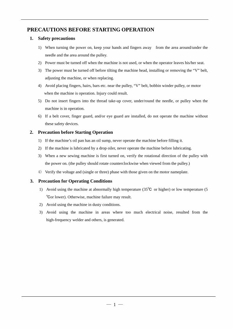
1. Adjustment of needle bar stop position
1)、When the pedal is kicked down by heel, the
machine stops at “UP”
2)、When the pedal is “Neutral” the machine stops
at “Down”
CAUTIONS ON USE
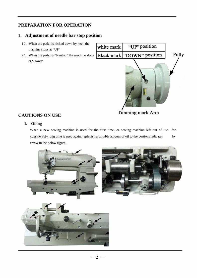
1. Oiling
When a new sewing machine is used for the first time, or sewing machine left out of use for
considerably long time is used again, replenish a suitable amount of oil to the portions indicated by
arrow in the below figure.
— 2 —

2. Adjustment of oiling to rotating hook
— 3 —
3. Cautions on operation
a) When the power is turned on or off, keep
foot away from the pedal.
b) It should be noted that the brake may not
work when the power is interrupted or power
failure occurs during sewing machine operation.
c) Since dust in the control box might cause
malfunction or control troubles, be sure to keep the control box cover close during operation.
d) Do not apply a multimeter to the control circuit for checking; otherwise voltage of multimeter
might damage semiconductor components in the circuit.
OPERATION
1. Installation of needles
Note: Before installing the needles, be sure to turn off the power.

2. Winding of bobbin thread
Note: When bobbin thread is wound, keep the presser foot lifted.
Adjustment:
— 4 —
3. Selection of thread It is recommended to use “S” twist thread in the
left needle (viewed from front), and “Z’ twist
thread in the right needle. When discriminate
use of needle threads is impossible, use “Z” twist
thread in both the needles.
For bobbin thread, “S” twist thread as well as “Z”
twist thread can be used.
4. Threading of needle threads a) Pass each needle thread through thread guide A
Note: When thin slippery thread (polyester Thread or
filament thread, for example) is used pass the
thread through thread guide B as well.
b) With the take-up lever located at the upper most position,
pass each needle thread in the order shown in the
following figure.
Note: Pressing the upper thread loosening button shown in the figure below
opens the saucer of the upper thread tension adjuster, and the upper thread can easily pulled out.

5. Adjustment of feed (stitch) length and stitch reversing (touch back)
Note: To make feed (stitch) length smaller, depress the feed reverse lever and set the feed length
setting dial to a desired position
Touch-back button . . . Direction of stitching can be reversed by depressing this button.
Stitching goes on in reversed direction while the button is held down, and returns to forward
direction when the button is released. .
6. Setting of bobbin
a) Pulling out 5.cm thread tail from the bobbin.
b) Hold the bobbin so that the bobbin thread is
would in right direction and put it into the hook.
— 5 —
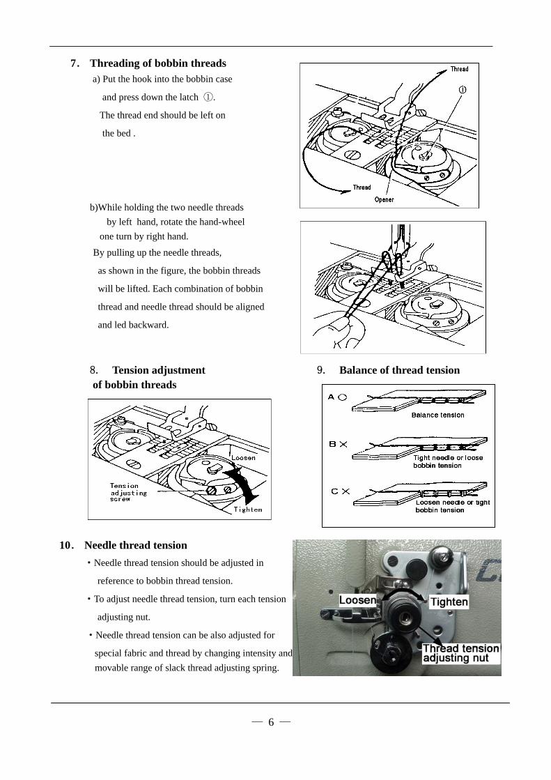
7. Threading of bobbin threads
a) Put the hook into the bobbin case
and press down the latch ①.
The thread end should be left on
the bed .
b)While holding the two needle threads
by left hand, rotate the hand-wheel
one turn by right hand.
By pulling up the needle threads,
as shown in the figure, the bobbin threads
will be lifted. Each combination of bobbin
thread and needle thread should be aligned
and led backward.
8. Tension adjustment 9. Balance of thread tension of bobbin threads
10. Needle thread tension
·Needle thread tension should be adjusted in
reference to bobbin thread tension.
·To adjust needle thread tension, turn each tension
adjusting nut.
·Needle thread tension can be also adjusted for
special fabric and thread by changing intensity and
movable range of slack thread adjusting spring.
— 6 —
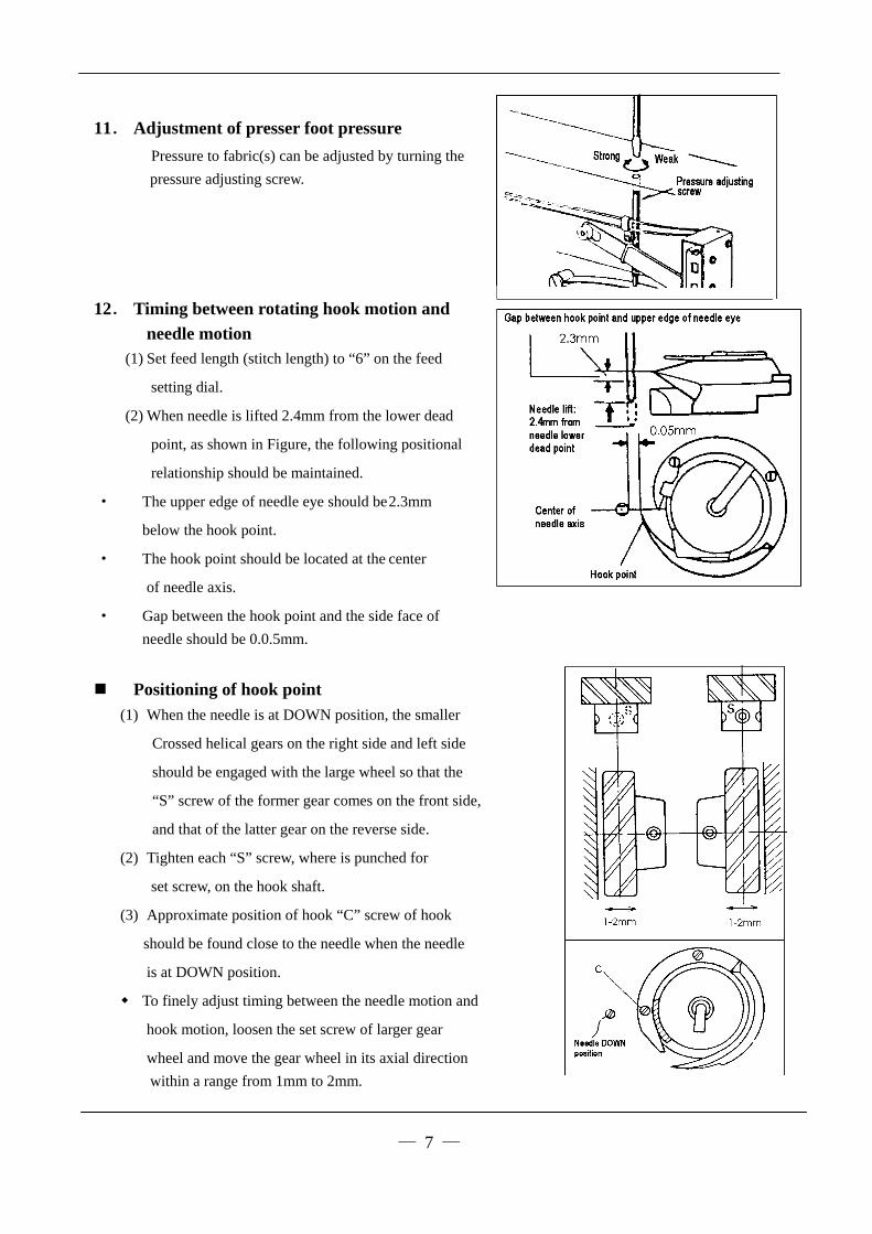
11. Adjustment of presser foot pressure
Pressure to fabric(s) can be adjusted by turning the
pressure adjusting screw.
12. Timing between rotating hook motion and
needle motion (1) Set feed length (stitch length) to “6” on the feed
setting dial.
(2) When needle is lifted 2.4mm from the lower dead
point, as shown in Figure, the following positional
relationship should be maintained.
· The upper edge of needle eye should be 2.3mm
below the hook point.
· The hook point should be located at the center
of needle axis.
· Gap between the hook point and the side face of
needle should be 0.0.5mm.
Positioning of hook point
(1) When the needle is at DOWN position, the smaller
Crossed helical gears on the right side and left side
should be engaged with the large wheel so that the
“S” screw of the former gear comes on the front side,
and that of the latter gear on the reverse side.
(2) Tighten each “S” screw, where is punched for
set screw, on the hook shaft.
(3) Approximate position of hook “C” screw of hook
should be found close to the needle when the needle
is at DOWN position.
To finely adjust timing between the needle motion and
hook motion, loosen the set screw of larger gear
wheel and move the gear wheel in its axial direction
within a range from 1mm to 2mm.
— 7 —

13. Adjustment of feed dog height
Height of feed dog and pressure of presser foot should
be adjusted for individual fabric(s) with the following
cautions:
· Fabric will be damaged if the feed dog extends too high,
or pressure of presser foot is too large.
· Even stitch length cannot be assured if the feed dog is
too low or pressure of presser foot is too small.
· Feed dog height should be measured at the point where
the needle is at the top position.
For light fabrics …… Approx. 0.8mm from throat plate
For usual fabrics …… Approx. 1.0mm from throat plate
For heavy fabrics …… Approx. 1.2mm from throat plate
Adjustment procedure
a) Lean the machine head backward.
b) Turn the hand wheel by hand and stop when the feed
dog rises to the maximum height.
c) Loosen the feed bar set screw.
d) Vertically move the feed bar (in the direction indicated by arrow in the figure) to adjust it to
adequate height.
e) After the adjustment, tighten the feed bar set screw.
The feed dog height is factory-adjusted to 1.2mm
14. Relationship between rotating hook motion and take-up lever motion
When the timing belt (toothed belt) was removed for
its replacement, for example, the relationship between
rotating hook motion and take-up lever motion should
be adjusted as follows:
a) Turn the balance wheel and stop when the take-up
lever is lifted to its upper dead point.
b) Lean the machine head backward and make sure the
arrow (timing mark) put on the timing belt is in
line with the black line on the boss of lower shaft bearing.
If the timing mark is not in line with the black line ,remove the timing belt and install it again to adjust.
— 8 —
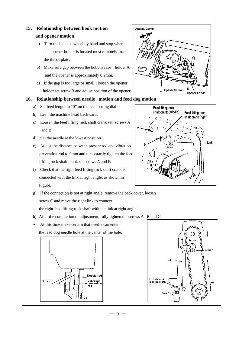
15. Relationship between hook motion
and opener motion
a) Turn the balance wheel by hand and stop when
the opener holder is located most remotely from
the throat plate.
b) Make sure gap between the bobbin case holder A
and the opener is approximately 0.2mm.
c) If the gap is too large or small , loosen the opener
holder set screw B and adjust position of the opener.
16. Relationship between needle motion and feed dog motion
a) Set feed length to “0” on the feed setting dial
— 9 —
b) Lean the machine head backward.
c) Loosen the feed lifting rock shaft crank set screws A
and B.
d) Set the needle at the lowest position.
e) Adjust the distance between presser rod and vibration
prevention rod to 9mm and temporarily tighten the feed
lifting rock shaft crank set screws A and B
f) Check that the right feed lifting rock shaft crank is
connected with the link at right angle, as shown in
Figure.
g) If the connection is not at right angle, remove the back cover, loosen
screw C and move the right link to connect
the right feed lifting rock shaft with the link at right angle.
h) After the completion of adjustment, fully tighten the screws A , B and C.
At this time make certain that needle can enter
the feed dog needle hole at the center of the hole.

17. Safety clutch device:
Safety clutch device is installed to prevent the hook
and cog belt from damage in case the thread is
caught into the hook when the machine is loaded
abnormally during operation.
(1) Function of safety clutch.
a) When the safety clutch acts, the cog belt pulley will be
unloaded. then the rotation of hook shaft will stop.
The arm shaft only will rotate. Stop the operation of
machine.
b) Clean the thread thoroughly which is caught into the hook.
c) Turn the cog belt hub by hand, and check whether the hook
Shaft rotates lightly and properly, place the clutch device as
follows.
(2) How to set the safety clutch.
a) While pressing down the push button on the
opposite side of bed by left hand, turn the
balance wheel slowly by right hand away
from you as shown in the figure.
b) The balance wheel will stop by the gear plate,
but turn the balance wheel more firmly.
c) Release the push button.
d) As shown in the Figure, the safety clutch device
is set.
— 10 —

(3) Force applied to the safety clutch.
a) The force applied to the safety clutch is the
smallest when the white mark of the eccentric
pin faces the center of the lower shaft. The
force proportionally increases as the white mark
faces the outside.
b) To adjust the force slide the timing belt, loosen
the set screw, and turn the eccentric pin.
c) After the adjustment, make sure to fasten the set screw.
18. Upper feed adjustment
(Needle side)
If the uneven feeding occurs according to the fabric,
adjust the long hole of the horizontal feed shaft
crank (right) to adjust the upper feed length.
(How to adjust)
a) Loosen the special bolt.
b) Move the special bolt upward to decrease upper feed.
c) Move the special bolt downward to increase the upper feed. The upper feed and the lower feed
theoretically becomes equal at the reference line on the horizontal feed shaft crank.
d) Securely tighten the special bolt after adjustment.
19. Outside presser foot and inside presser vertical stroke adjustment
When fabric with large elasticity is sewn, or when
thickness of fabric changes, the vertical stroke
(movable range) of the presser feet should be
adjusted as follows:
Adjustment
a) Loosen the special bolt.
b) The vertical strokes of the presser feet become
c) maximum when the crank rod is moved upward and set.
d) The vertical strokes becomes minimum when the nut
is moved downward and set.
e) After the adjustment, fully tighten the special bolt.
The vertical strokes of the presser feet can be adjusted within a range from 6mm to 2mm.
— 11 —

20. Adjustment
Screwing the pin that connects the link of back-sewing with the crank of back-sewing (down) can adjust
the tolerance of between the stitches. Screwing the pin in clockwise can increase the stitch of forward
sewing; otherwise, the stitch of back-sewing will be increased.
21. Installation of movable knife
(1) Installation of movable knife
a. Turn the balance wheel and lower the needle bar to the lowest position.
b. Push the cam follower crank so that the cam roller enters into the thread trimmer cam groove.
c. Turn the balance wheel until the black mark point on the arm meets the white mark point on the
balance wheel. Set the cam follower crank at this position with a screwdriver temporarily preventing
the cam roller coming out from the cam groove.
d. Loosen the thread trimmer rocking crank clamp bolts A and B.
e. Adjust the movable knife so that the movable knife end slant portion protrudes
0-0.5 mm from the fixed knife, as shown in Figure and tighten the bolts A and B.
— 12 —
(2) Gap between movable knife and bobbin case holder stopper
a. Turn the balance wheel by hand until needle reaches the
Lowest position.
b. With the needle at the lowest position, depress cam follower
crank, turn the balance wheel until the movable knife reaches
the extremity of its stroke.
c. Manually rotate the inner hook in the direction indicated by
arrow in Figure and adjust gap between the movable knife
and the inner hook stopper to about 0.5 mm (the screws A and B should be loosened for this adjustment).
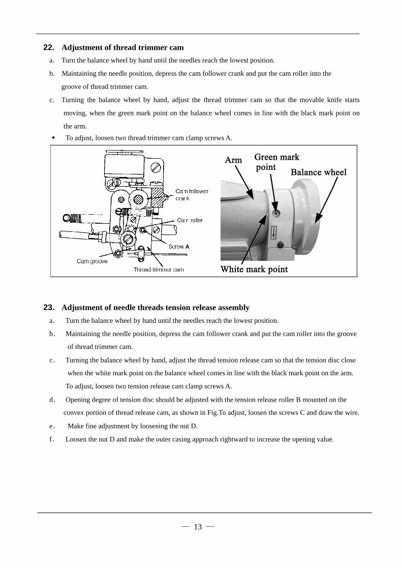
22. Adjustment of thread trimmer cam
a. Turn the balance wheel by hand until the needles reach the lowest position.
b. Maintaining the needle position, depress the cam follower crank and put the cam roller into the
groove of thread trimmer cam.
c. Turning the balance wheel by hand, adjust the thread trimmer cam so that the movable knife starts
moving, when the green mark point on the balance wheel comes in line with the black mark point on
the arm.
To adjust, loosen two thread trimmer cam clamp screws A.
23. Adjustment of needle threads tension release assembly
a. Turn the balance wheel by hand until the needles reach the lowest position.
b. Maintaining the needle position, depress the cam follower crank and put the cam roller into the groove
of thread trimmer cam.
c. Turning the balance wheel by hand, adjust the thread tension release cam so that the tension disc close
when the white mark point on the balance wheel comes in line with the black mark point on the arm.
To adjust, loosen two tension release cam clamp screws A.
d. Opening degree of tension disc should be adjusted with the tension release roller B mounted on the
convex portion of thread release cam, as shown in Fig.To adjust, loosen the screws C and draw the wire.
e. Make fine adjustment by loosening the nut D.
f. Loosen the nut D and make the outer casing approach rightward to increase the opening value.
— 13 —

24. Adjustment of scissoring pressure of movable knife and fixed knife
a. Loosen the fixed knife bracket clamp bolt A.
b. Turn the vertical position adjusting screw B to adjust meshing pressure and then righter the hexagon
socket head cap screw A.
— 14 —
Note: Since excess pressure causes large
torque to the thread trimming mechanism
and trimming failure, adjust it so that
thread can be trimmed with minimum
pressure.
c. Move the movable knife and check that
the thread can be sharply trimmed.
25. Sharpening of fixed knife
When the knives dull, the fixed should
be sharpened as illustrated in Fig.
Since it is very difficult to sharpen the movable knife,
replace it with a new one when it dulls.
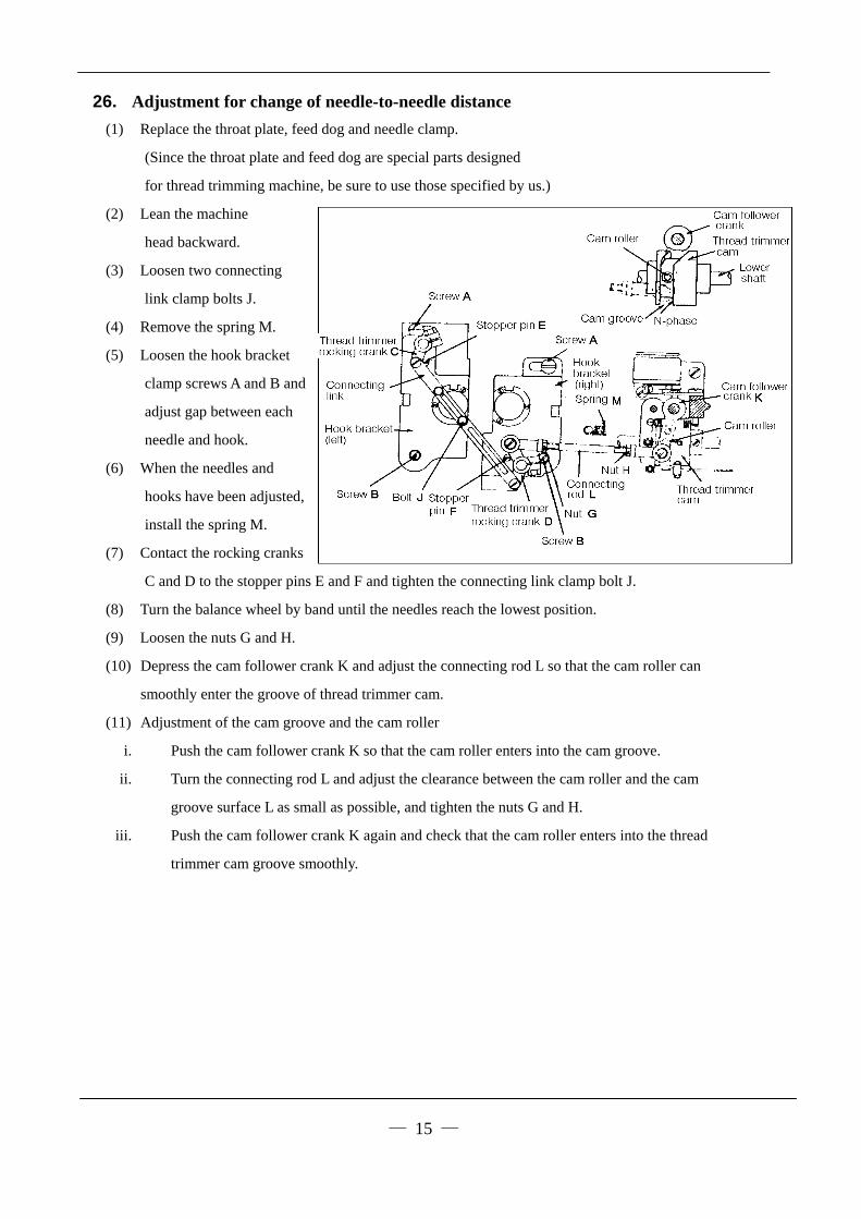
26. Adjustment for change of needle-to-needle distance
(1) Replace the throat plate, feed dog and needle clamp.
(Since the throat plate and feed dog are special parts designed
for thread trimming machine, be sure to use those specified by us.)
(2) Lean the machine
head backward.
— 15 —
(3) Loosen two connecting
link clamp bolts J.
(4) Remove the spring M.
(5) Loosen the hook bracket
clamp screws A and B and
adjust gap between each
needle and hook.
(6) When the needles and
hooks have been adjusted,
install the spring M.
(7) Contact the rocking cranks
C and D to the stopper pins E and F and tighten the connecting link clamp bolt J.
(8) Turn the balance wheel by band until the needles reach the lowest position.
(9) Loosen the nuts G and H.
(10) Depress the cam follower crank K and adjust the connecting rod L so that the cam roller can
smoothly enter the groove of thread trimmer cam.
(11) Adjustment of the cam groove and the cam roller
i. Push the cam follower crank K so that the cam roller enters into the cam groove.
ii. Turn the connecting rod L and adjust the clearance between the cam roller and the cam
groove surface L as small as possible, and tighten the nuts G and H.
iii. Push the cam follower crank K again and check that the cam roller enters into the thread
trimmer cam groove smoothly.

— 16 —
SPECIFICATIONS
Model 255RATCWL(E)-1 339RBCWL(E)-1
Number Single-needle Double-needle
Application Heavy material
Max.sewing speed 1800(rpm)
Stitch length 0~9(mm)
Thread take-up lever stroke 74.5(mm)
Needle-bar stroke 36(mm)
Presser-foot stroke 16(mm) by Leg 8(mm) by hand
Vertical stroke of upper feed 2~6(mm)
Needle No. DP×17 #23
Hook (Horizontal full-rotating) Large
Thread take-up lever Slide lever
Stitch adjusting system Dial
Lubrication system Manual lubrication
Motor Clutch motor 370W Servo motor 550W
Standard 6.4(mm) Needle
gauge Special 3.2 4 4.8 8 9.5 12.7 16 19 25.4(mm)
Note: ◆ Some materials, gauge sizes, and/or sewing conditions may require specifications other than
those listed above.
◆ Feed dog, throat plate, rotating hook, bobbin case and bobbin should be those designed for thread
timer.
◆ Bobbin should be of high quality free from deformation.
◆ This specification is subject to change for machine improvement.