Embed Size (px)
Citation preview
Precise Measurements of Small Linear and Angular Displacements with Capacitance Methods
Sergio Rescia
• Motivation: EDM G-2 Upgrade (by Gerald Bennet)
• Types of Displacement and Angle Sensors
• Advantages of Capacitive Displacement Sensors
• Readout Methods
• Limits to Sensitivity: Electrical and Mechanical Noise
• MEMS/Microelectronics Applications: Accelerometers
Acknowledgment:
The EDM Collaboration, especially G. Bennet, R. Burns, W. Morse, Y. Semertzidis, L. Snydstrup
P. Rehak
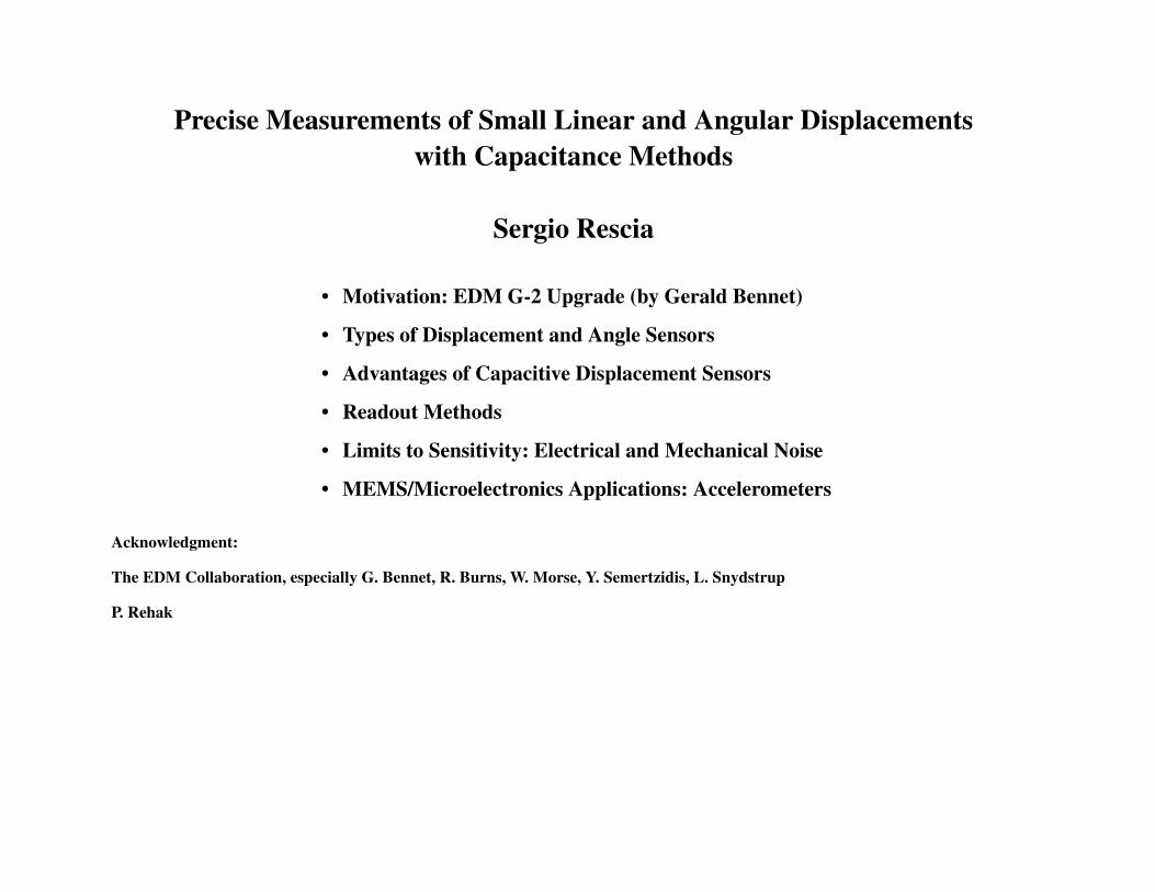
Types of Displacement and Angle Sensors
1: Interferometric Sensor
• interferometric technique: optical wavelength-scale resolution
• Measures relative movements: laser light must be on all the time unless the reference point is lost

Types of Displacement and Angle Sensors
2: Interpolating Sensors (e.g SONY MAGNESCALE)
• Uses spatial averaging: reduced differential non-linearity
• Large Dynamic range
• Integral non-linearity depends on accumulated error in N-S magnetization locations

Types of Displacement and Angle Sensors (cont)
LVDT: Linear Variable Differential Transformer
A ferromagnetic core moves with respect to two opposite windings, changing the coupled flux.
• S-shaped characteristics
• Bulky
• Slow response (uses low frequency)
• Sensitive to magnetic fields
• It is the most widely used displacement sensor
OSC AMP
AMP VOUT
LVDT
EXCITATION (CARRIER)
11
17
1016
23
FILTERA–BA+B
VB
VA
AD598
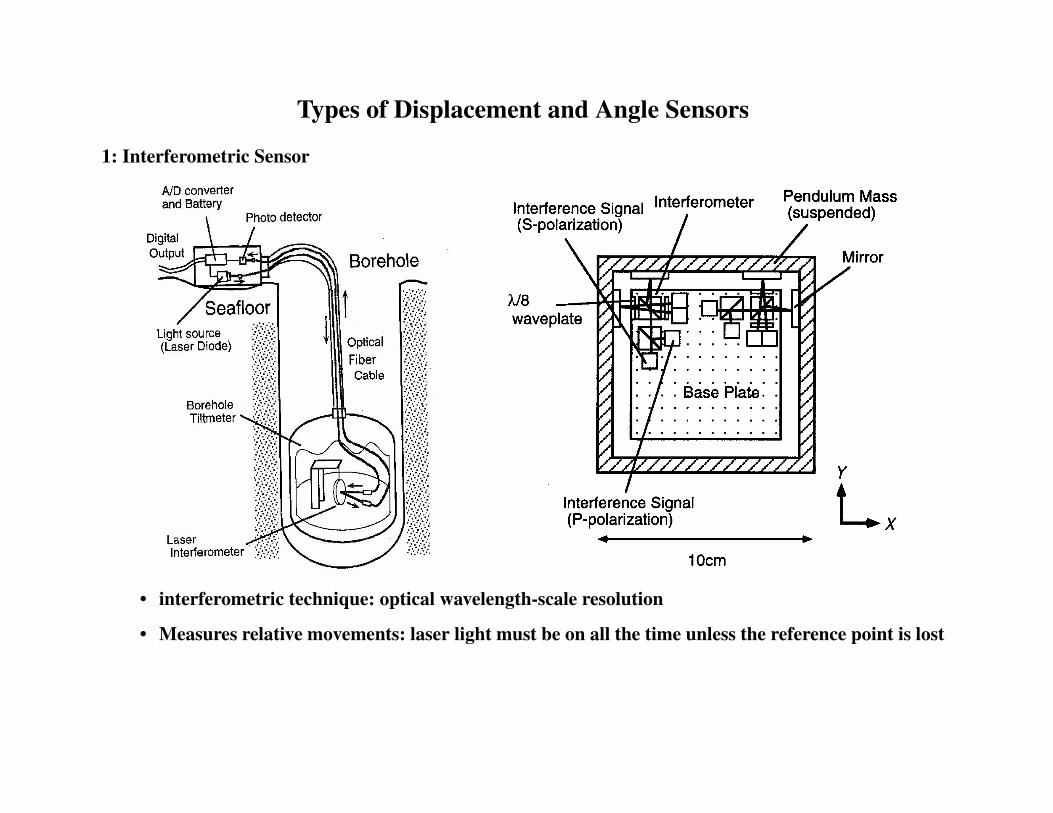
Types of Displacement and Angle Sensors (cont)
CAPACITIVE SENSORS
Piston type variable Capacitor
Differential Capacitors
f~1 MHz
C2
C1
C2
C1SUPPORT

Advantages of Capacitive Sensors
• Excellent linearity over entire dynamic range when Area is changed (since stray electric fields
are small)
• The system responds to average displacement of a large area of a moving electrode
• Freedom of electrode materials and geometry for demanding environments and applications
• Fractional change in capacitance can be made large
• Capacitive sensors can be made to respond to displacements in one direction only
• The forces exerted by the measuring apparatus are electrostatic, and usually small enough so
that they can be disregarded
• Capacitors are noiseless: excellent S/N ratio can be obtained (or their dissipation factor D is large
enough that the dominant noise sources are elsewhere)
C ε Ad---⋅=
Vary A => better linearity
Vary d => better sensitivity over small displacement

Types of Readout
Two major categories: 1. Readout based on Resonance
2. Readout based on Bridge method
Readout based on Resonance
1. Measure frequency change of an oscillator built around the variable capacitor
1. Excite at resonance, measure amplitude change
2. Excite at resonance, measure phase change
3. Use feedback loop and VCO oscillator to track resonance change
R L C
V
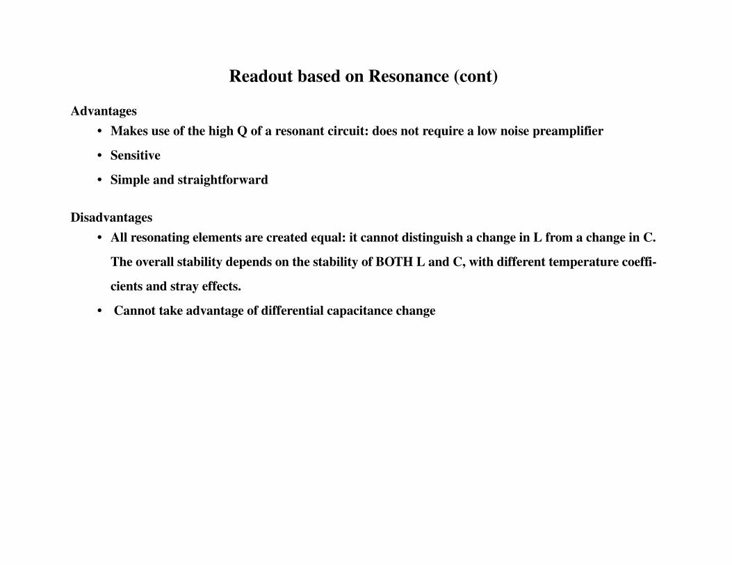
Readout based on Resonance (cont)
Advantages
• Makes use of the high Q of a resonant circuit: does not require a low noise preamplifier
• Sensitive
• Simple and straightforward
Disadvantages
• All resonating elements are created equal: it cannot distinguish a change in L from a change in C.
The overall stability depends on the stability of BOTH L and C, with different temperature coeffi-
cients and stray effects.
• Cannot take advantage of differential capacitance change
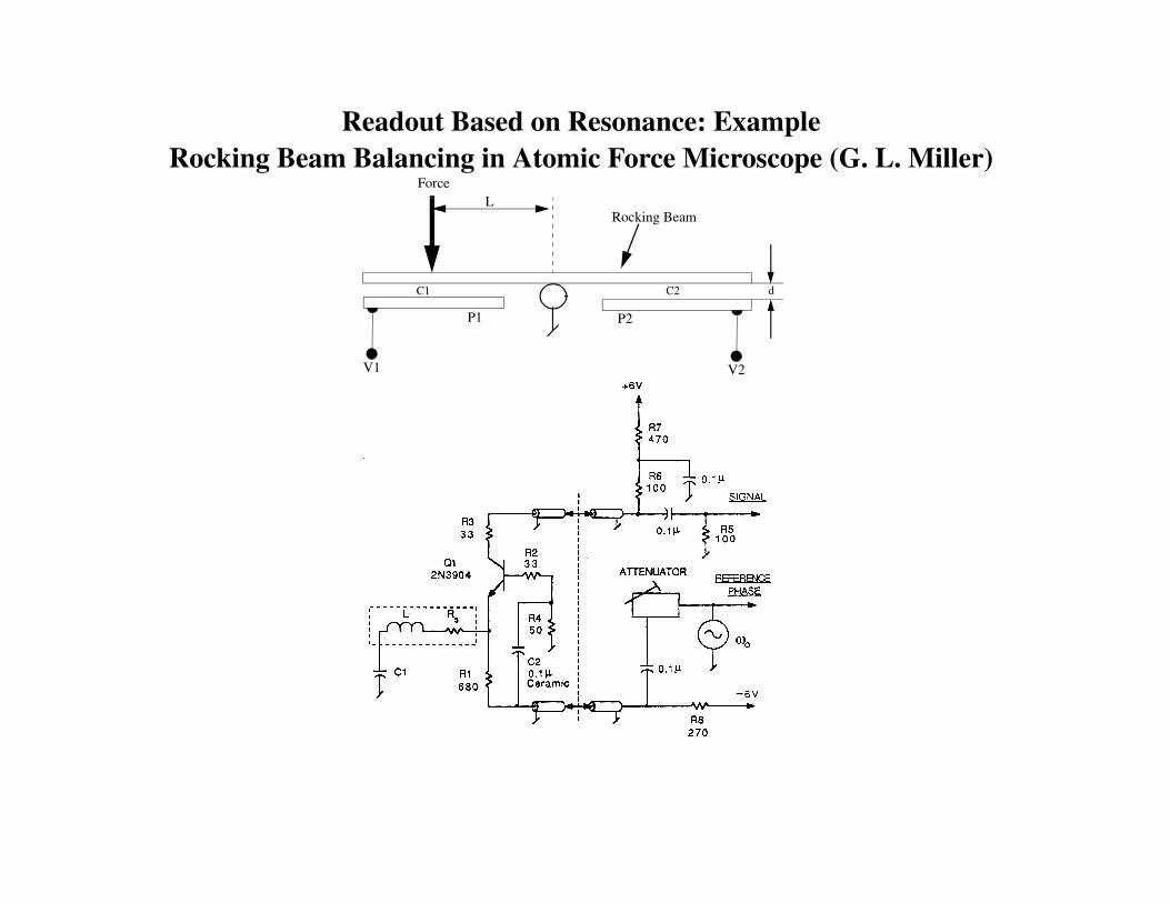
Readout Based on Resonance: ExampleRocking Beam Balancing in Atomic Force Microscope (G. L. Miller)
V2V1
L
P2P1
Force
Rocking Beam
C2C1 d

Types of Readout: AC Bridge
C1
C2
C1 - C2 = εεεε A/(δδδδx - x0) - εεεε A/(δδδδx + x0) = 2 C0 δδδδx/x0
~
~
A=400 mm2 x0 = 75 µµµµm C1 = C2 = 50 pF
l = 30 mm δθδθδθδθ= 1 nrad δδδδx = δθδθδθδθ l = 30 10-12 m δδδδC = C1 - C2 = 40 aF
iD~
C1
C2
+V1
-V1
iD = V1 ω ω ω ω (C1 -C2)
Force12---
C1x0------ V1
2⋅ ⋅= F = 0 for a symmetric system
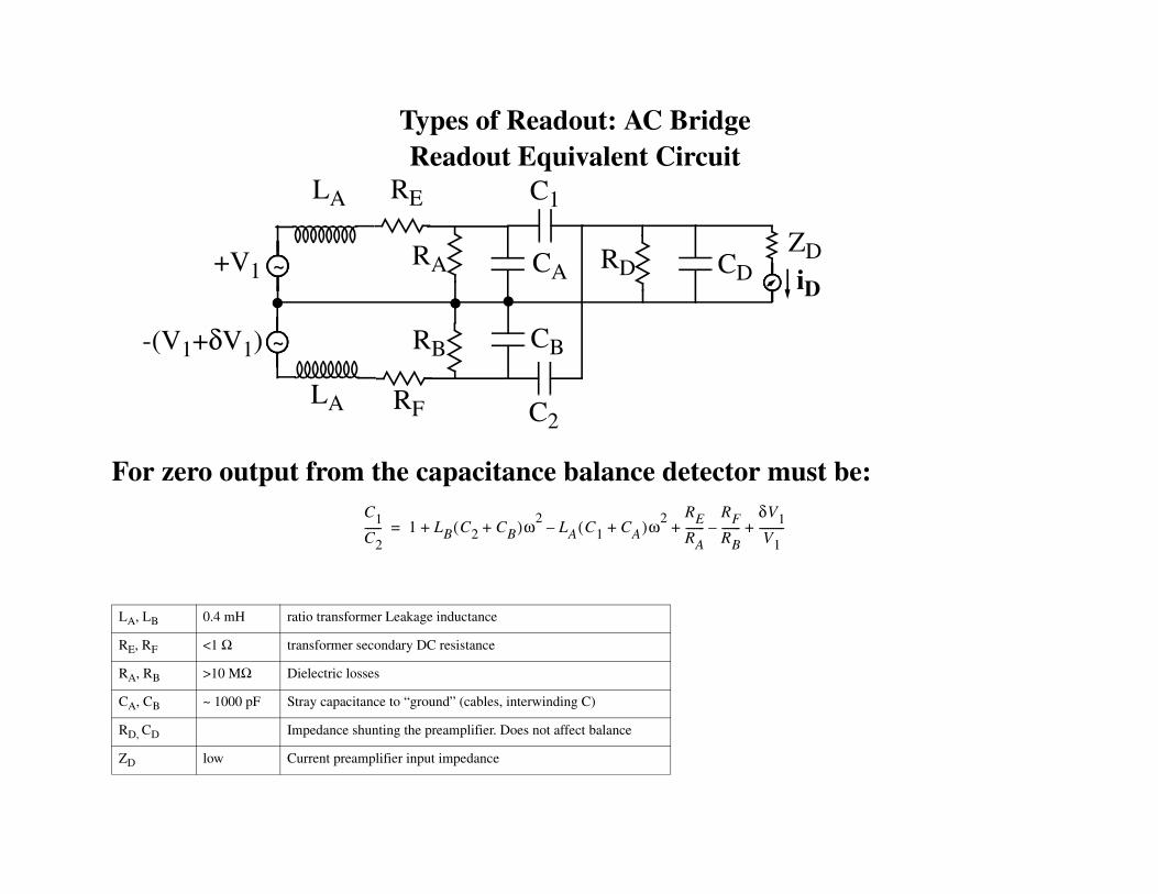
Types of Readout: AC BridgeReadout Equivalent Circuit
For zero output from the capacitance balance detector must be:
LA, LB 0.4 mH ratio transformer Leakage inductance
RE, RF <1 Ω transformer secondary DC resistance
RA, RB >10 MΩ Dielectric losses
CA, CB ~ 1000 pF Stray capacitance to “ground” (cables, interwinding C)
RD, CD Impedance shunting the preamplifier. Does not affect balance
ZD low Current preamplifier input impedance
~+V1
-(V1+δV1) ~
LA
LA
RE
RF
RA
RB
CA
CB
C2
C1
RD CDZDiD
C1C2------ 1 LB C2 CB+( )ω2
LA C1 CA+( )ω2 RE
RA-------
RF
RB-------
δV1V1
---------+–+–+=
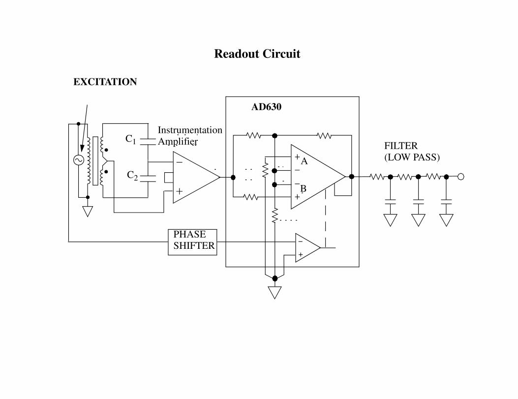
Readout Circuit
EXCITATION
AD630
PHASESHIFTER
FILTER(LOW PASS)A
B
InstrumentationAmplifierC1
C2

AC Bridge: Noise
The “equivalent noise capacitance” can be calculated as:
so that we have:
C1
C2
CDiD
en
in~
~
V1
V1
iD n,2
in2 en
2
1 ω02CT
2⁄---------------------+
BW=
CT C1 C2 CD+ +=
in2 en
2
1 ω02CT
2⁄---------------------+
BWV1
2
1 ω02Cn
2( )⁄-----------------------------=
Cn2 1
V12
------ en2CT
2in2
ω02
---------+
BW=
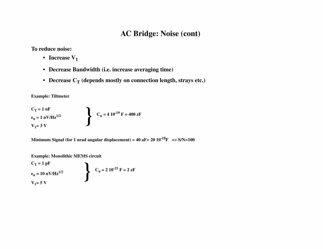
AC Bridge: Noise (cont)
To reduce noise:
• Increase V1
• Decrease Bandwidth (i.e. increase averaging time)
• Decrease CT (depends mostly on connection length, strays etc.)
Example: Tiltmeter
CT = 1 nF
en = 1 nV/Hz1/2
V1= 3 V
Minimum Signal (for 1 nrad angular displacement) = 40 aF= 20 10-18F => S/N=100
Example: Monolithic MEMS circuit
CT = 1 pF
en = 10 nV/Hz1/2
V1= 5 V
Cn = 4 10-19 F = 400 zF
Cn = 2 10-21 F = 2 zF

Mechanical Noise
The mechanical rms fluctuation can be computed by means of the fluctuation dissipation theorem.The rms fluctuation of the displacement of a suspended mass m is:
Where:
kB = 1.38 1023 J/K
m ~ 20 g
ωωωω0 = mechanical resonant frequency ~105 rad/sec
τ =τ =τ =τ = damping time constant ~ 5-10 sec
S = Averaging period ~ 1 sec
So that (δδδδx2)(1/2) ~ 10-17 m giving a “noise” too small to be detected.
Absolute Limits:
Since the damping could be increased (e.g. using more dense fluid to increase friction) there is no fundamental
limit to the mechanically generated noise
δx2 kBT
mω02τS
------------------≅
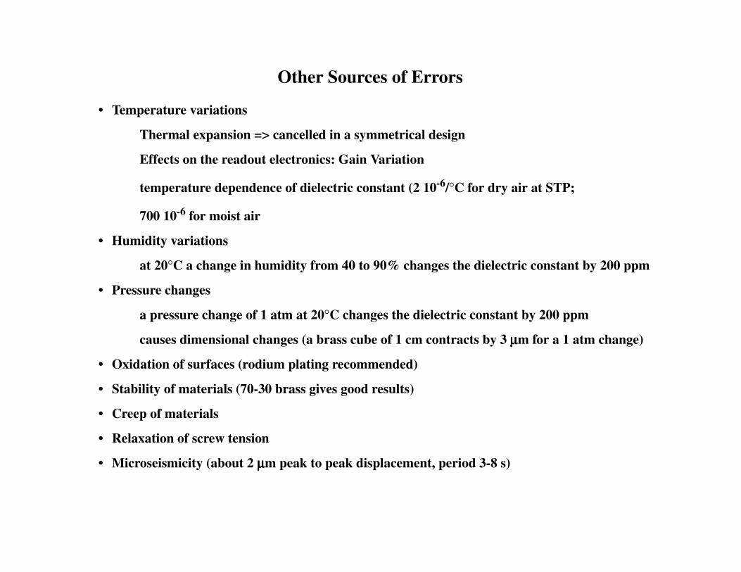
Other Sources of Errors
• Temperature variations
Thermal expansion => cancelled in a symmetrical design
Effects on the readout electronics: Gain Variation
temperature dependence of dielectric constant (2 10-6/°C for dry air at STP;
700 10-6 for moist air
• Humidity variations
at 20°C a change in humidity from 40 to 90% changes the dielectric constant by 200 ppm
• Pressure changes
a pressure change of 1 atm at 20°C changes the dielectric constant by 200 ppm
causes dimensional changes (a brass cube of 1 cm contracts by 3 µµµµm for a 1 atm change)
• Oxidation of surfaces (rodium plating recommended)
• Stability of materials (70-30 brass gives good results)
• Creep of materials
• Relaxation of screw tension
• Microseismicity (about 2 µµµµm peak to peak displacement, period 3-8 s)

MEMS Accelerometers
It consist of multiple fingers on each side of a movable center member.
They constitute the center plates of a paralleled set of differential capacitors. Pairs of fixed fingers attached to the substrate interleave with the beam fingers to form the outer capacitor plates. The beam i9s supported by tethers which serve as mechanical spring.
“Force” fingers are used for calibration
mass = 0.5 µµµµg
SIZE: 0.5 mm x 0.4 mm, 2 µµµµm thick,
• Requirement: Avoid “stiction” => rigid cantilevered beam
FOLDED TETHER
BEAM
SENSEFINGERS
AXIS OFACCELERATION
FORCEFINGERS
TETHER
ANCHOR
BEAM
SENSEFINGERS
AXIS OFACCELERATION
FORCEFINGERS
TETHER
ANCHOR

Sensor operation; ADI’s implementationSensor operation; ADI’s implementation• Folded tethers have more consistent spring constants,
leading to better part to part consistency• Folded tethers have more consistent spring constants,
leading to better part to part consistency
PROOF MASS (BEAM)PROOF MASS (BEAM)
TETHERTETHER
TOP VIEWTOP VIEW
ANCHOR ANCHORFIXEDFIXEDOUTEROUTERPLATESPLATES
CS1 < CS2CS1 < CS2
APPLIEDAPPLIEDACCELERATIONACCELERATION

Self test operationSelf test operation
• Extra fixed outer plates may be added which when exited, force the proof mass to move. So you can electronically test the accelerometer
• Extra fixed outer plates may be added which when exited, force the proof mass to move. So you can electronically test the accelerometer
Additional fixed outer plates are electricallyAdditional fixed outer plates are electricallyexcited to induce movement of the proof mass.excited to induce movement of the proof mass.Acceleration is measured by the standard fixedAcceleration is measured by the standard fixedplates as usual.plates as usual.

Interesting facts Interesting facts
• 0.1µgrams Proof Mass• 0.1pF per Side for the Differential Capacitor• 20aF (10-18f) Smallest Detectable Capacitance Change• Total Capacitance Change for Full-scale is 10fF• 1.3µm Gaps Between Capacitor Plates• 0.2Å Minimum Detectable Beam Deflection (one tenth
of an Atomic diameter)• 1.6 µm Between the Suspended Beam and Substrate• 10 to 22kHz Resonant Frequency of Beam
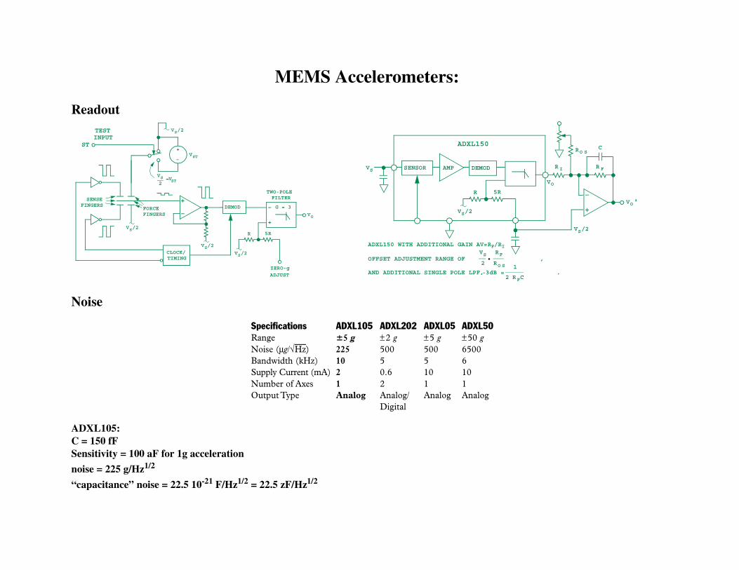
MEMS Accelerometers:
Readout
Noise
ADXL105: C = 150 fFSensitivity = 100 aF for 1g acceleration
noise = 225 g/Hz1/2
“capacitance” noise = 22.5 10-21 F/Hz1/2 = 22.5 zF/Hz1/2
+
–
VS2
VST
VS/2
VST
DEMOD
CLOCK/TIMING
VS/2
VS/2
FORCEFINGERS
SENSEFINGERS
VS/2
ZERO-g
ADJUST
–
+
G = 3
VO
TWO-POLEFILTER
R 5R
ST
TESTINPUT
-
DEMODSENSOR
R 5R
VS/2
AMP
ADXL150
VO
R I
RO S
VS
VO'
R F
C
VS/2
ADXL150 WITH ADDITIONAL GAIN AV=RF/RI
OFFSET ADJUSTMENT RANGE OF ,
AND ADDITIONAL SINGLE POLE LPF, -3dB = .
VS
2
RF
RO S 1
2 RFC
Specifications ADXL105 ADXL202 ADXL05 ADXL50Range 5 g ±2 g ±5 g ±50 gNoise (µg/√Hz) 225 500 500 6500Bandwidth (kHz) 10 5 5 6Supply Current (mA) 2 0.6 10 10Number of Axes 1 2 1 1Output Type Analog Analog/ Analog Analog
Digital
Bibliography
1. G.L. Miller “Sensor and actuators for small motions”, unpublished report available from S. Rescia
2. R.V. Jones and C. S. Richards, “The design and some application of sensitive capacitance voltmeters”,
J. Phys. E 6, 589 (1973)
3. A. M. Thomson, “The precise measurements of small capacitances”, IRE Trans. Instrum, I-7, 245 (1958)
4. G. L. Miller, E. R. Wagner and T. Sleator, “Resonant phase technique for the measurement of small changes in grounded
capacitors”, Rev. Sci. Instrum., 61 (4), 1287 (1990)
5. H. W. Callen and R. F. Greene, “On a theorem of irreversible thermodinamics”, Phys. Rev., 86 (5), 702 (1952)
6. P. S. Saulton, “Thermal noise in mechanical experiments”, Phys. Rev. D 42, 2437 (1990)
7. A good tutorial on random noise in mechanical system as applied to gravitational wave antennas is in P. S. Saulton
“Physics of gravitational wave detection: resonant and interferometric detectors” available at “http://www.astro.psu.edu/
users/steinn/Astro597/saulson.pdf”