Embed Size (px)
Citation preview
Precision Dovetail Slides• DS Series • TS Series • M Series
• Slide Widths from 2"–16"

2
3
Express DS Basic Model
Select DS Hand Feed Model With Feedscrew
Direct Drive Gear Motor and Disengaging Handwheel mounted on opposite end for manual positioning
Introducing the DS Family of MASTER/SETCO Dovetail Slides
1
CUSTOMSLIDES
Express DS Series• One week shipment!
The Express DS Slide Series is for applications wherecompact design and immediate delivery are essential.Available in the most popular sizes of 4", 6", 8", 10" or 12" base widths, they are factory assembled from off-the-shelf components and shipped to you ready to install.
Shipment is within one week after order placement. For multiple quantities of slides, consult factory for delivery.
Select DS Series• Wide range of sizes and accessories.• Shipments as short as three weeks.
The Select DS Slide Series offers you a wider choice in drive styles, accessories and sizes. Base and saddlelengths are available in 1" increments up to 64".
Ideal for use in work feeders, positioning fixtures, workholding devices, shuttle devices and assembly equipment, Select DS Slides are factory assembled, tested and shipped to you ready to install.
Shipment is within three to five weeks from the time your order is placed. For multiple quantities of slides, consultfactory for delivery.
Super Select DS Series• Engineered around a standard product building block.• Allows modification to meet your application
requirements.• Reduces excessive leadtime and cost premiums.
The Super Select DS Slide Series is designed around a standard baseline platform. Such a modular design allows our Team of Solutions Engineers the flexibility to createa slide that will virtually match your application needs in sizeand capability…but without excessive leadtimes and cost pre-miums that are often associated with custom designed slides.
All Super Select slides are factory engineered, manufactured, assembled, runoff and shipped to you ready to install. Leadtime is contingent on the complexity of your slide design.
ONE WEEK
SHIPMENT
THREE WEEK
SHIPMENT
DS Series
NOTE: Due to continual improvements, specifications are subject to change without notice. For current specifications, request a certified print when placing your order. © 2004 SETCO® and MASTER/SETCOTM are trademarks of SETCO Sales Company.
3
Page 4
Page 23
Page 34
Quick-Reference Index
Design Data
Page 50
Precision Slide Solutions
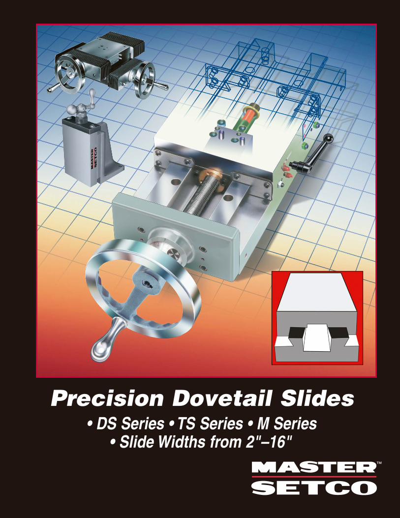
“DS” Series Dovetail Slides• 100% Solid Model Design
This state-of-the-art dovetail slide is an ideal choice for assembly, test, gauge, motion control and machiningapplications. Available in the most popular sizes of base
widths, DS slides are factory assembled from off-the-shelf components and shipped to you ready to install. Three distinct DS Series are available:• Express DS – Shipment in one week on basic and hand
feed models. Base widths are available in 4", 6", 8", 10" and 12".
• Select DS – Shipment in three to five weeks. Widths to 16". Lengths in 1" increments to 64". Available with a wider range of drive styles and accessories.
• Super Select DS – Everything you want in a custom slide – built right in.
Off-The-Shelf Standard and Heavy Duty “TS” Series Dovetail Slides • “TS” Series Extended Saddle
The reliable TS Series is an excellent tool slide choice whenyou have precision positioning, feeding, gauging, inspection orlathe applications. Designed with an extended saddle, theserugged cast-iron slides provide increased reach with reducedinterference. The standard duty low profile TS includes 2"through 6" wide bases. A heavier duty high profile HTS modeloffers increased load capacity and base widths up to 8".
In-Stock “M” Series Dovetail Slides • Includes Hand Feed Package
With in stock availability, the M Series is your ideal choice for no-wait replacement of current M slides, or for replacing otherdesigns that require compounding or angle plate mounting. The reliable M Series is well-suited for your new slide designsthat can adapt to pre-engineered sizes. The saddle and base come pre-drilled for quick assembly. A wide variety of standard attachments, such as angle plates,rotary swivel tables, accordion way covers and right angle drives, are available to meet diverse requirements. Width sizes range from 2" to 10".
Page 6
Page 11
Page 17
EXPRESS DS
SELECT DS
SUPER SELECT DS
Page 46M SERIES APPLICATION PHOTOS
TSSERIES SLIDES
MSERIES SLIDES
DSSERIES SLIDES
To Place Your OrderPhone: 1-800-543-0470 Fax: 1-513-941-6913
Email: [email protected]
4
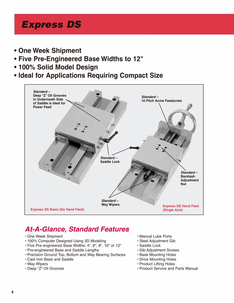
• One Week Shipment • Five Pre-Engineered Base Widths to 12"• 100% Solid Model Design• Ideal for Applications Requiring Compact Size
Express DS Basic (No Hand Feed)
At-A-Glance, Standard Features • One Week Shipment• 100% Computer Designed Using 3D Modeling• Five Pre-engineered Base Widths: 4", 6", 8", 10" or 12"• Pre-engineered Base and Saddle Lengths• Precision Ground Top, Bottom and Way Bearing Surfaces• Cast Iron Base and Saddle• Way Wipers• Deep “Z” Oil Grooves
Express DS Hand Feed(Single Axis)
• Manual Lube Ports• Steel Adjustment Gib• Saddle Lock• Gib Adjustment Screws• Base Mounting Holes• Drive Mounting Holes• Product Lifting Holes• Product Service and Parts Manual
Standard –Saddle Lock
Standard – 10 Pitch Acme Feedscrew
Standard –Way Wipers
Standard –BacklashAdjustmentNut
Standard – Deep “Z” Oil Groovesin Underneath Sideof Saddle is Ideal forPower Feed
Express DS
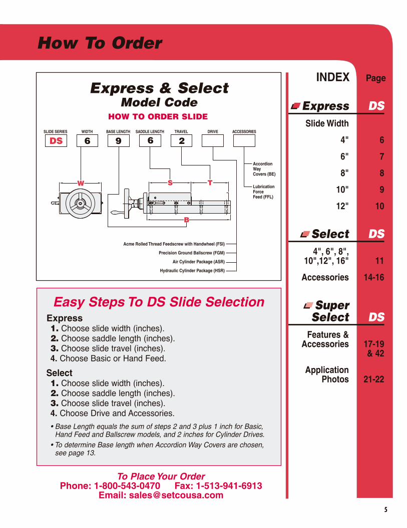
SLIDE SERIES WIDTH BASE LENGTH SADDLE LENGTH TRAVEL DRIVE ACCESSORIES
DS 6 9 6 2
Acme Rolled Thread Feedscrew with Handwheel (FSI)
Precision Ground Ballscrew (FGM)
Air Cylinder Package (ASR)
Hydraulic Cylinder Package (HSR)
Accordion Way Covers (BE)
Lubrication ForceFeed (FFL)
W S T
B
INDEX Page
Express DSSlide Width
4" 6
6" 7
8" 8
10" 9
12" 10
Select DS4", 6", 8",
10",12", 16" 11
Accessories 14-16
Super Select DS
Features & Accessories 17-19
& 42
Application Photos 21-22
Easy Steps To DS Slide SelectionExpress1. Choose slide width (inches).2. Choose saddle length (inches).3. Choose slide travel (inches).4. Choose Basic or Hand Feed.
Select1. Choose slide width (inches).2. Choose saddle length (inches).3. Choose slide travel (inches).4. Choose Drive and Accessories.
• Base Length equals the sum of steps 2 and 3 plus 1 inch for Basic,Hand Feed and Ballscrew models, and 2 inches for Cylinder Drives.
• To determine Base length when Accordion Way Covers are chosen, see page 13.
Express & SelectModel Code
HOW TO ORDER SLIDE
5
How To Order
To Place Your OrderPhone: 1-800-543-0470 Fax: 1-513-941-6913
Email: [email protected]
6
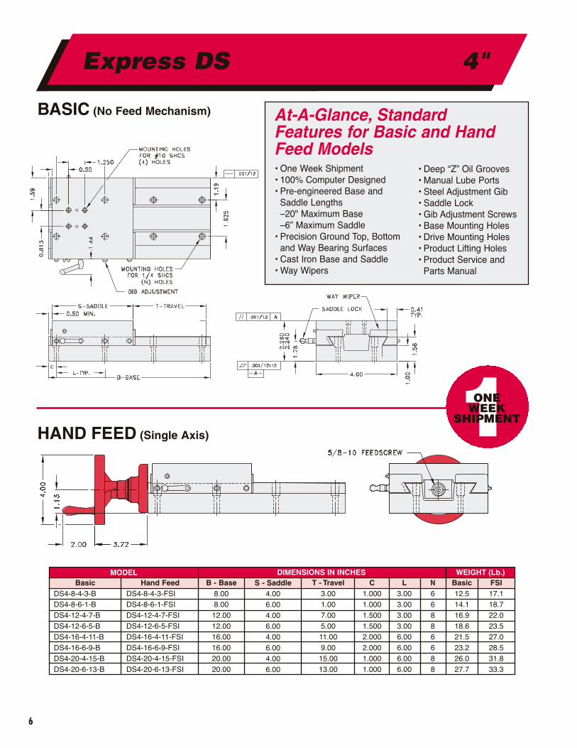
BASIC (No Feed Mechanism)
HAND FEED (Single Axis)
Express DS 4"
MODEL DIMENSIONS IN INCHES WEIGHT (Lb.)Basic
DS4-8-4-3-BDS4-8-6-1-BDS4-12-4-7-BDS4-12-6-5-BDS4-16-4-11-BDS4-16-6-9-BDS4-20-4-15-BDS4-20-6-13-B
Hand FeedDS4-8-4-3-FSIDS4-8-6-1-FSIDS4-12-4-7-FSIDS4-12-6-5-FSIDS4-16-4-11-FSIDS4-16-6-9-FSIDS4-20-4-15-FSIDS4-20-6-13-FSI
B - Base8.008.0012.0012.0016.0016.0020.0020.00
S - Saddle4.006.004.006.004.006.004.006.00
T - Travel3.001.007.005.0011.009.0015.0013.00
C1.0001.0001.5001.5002.0002.0001.0001.000
L3.003.003.003.006.006.006.006.00
N66886688
Basic12.514.116.918.621.523.226.027.7
FSI17.118.722.023.527.028.531.833.3
• Deep “Z” Oil Grooves• Manual Lube Ports• Steel Adjustment Gib• Saddle Lock• Gib Adjustment Screws• Base Mounting Holes• Drive Mounting Holes• Product Lifting Holes• Product Service and
Parts Manual
At-A-Glance, StandardFeatures for Basic and HandFeed Models• One Week Shipment• 100% Computer Designed • Pre-engineered Base and
Saddle Lengths –20" Maximum Base–6” Maximum Saddle
• Precision Ground Top, Bottom and Way Bearing Surfaces
• Cast Iron Base and Saddle• Way Wipers
1ONE WEEK
SHIPMENT
7
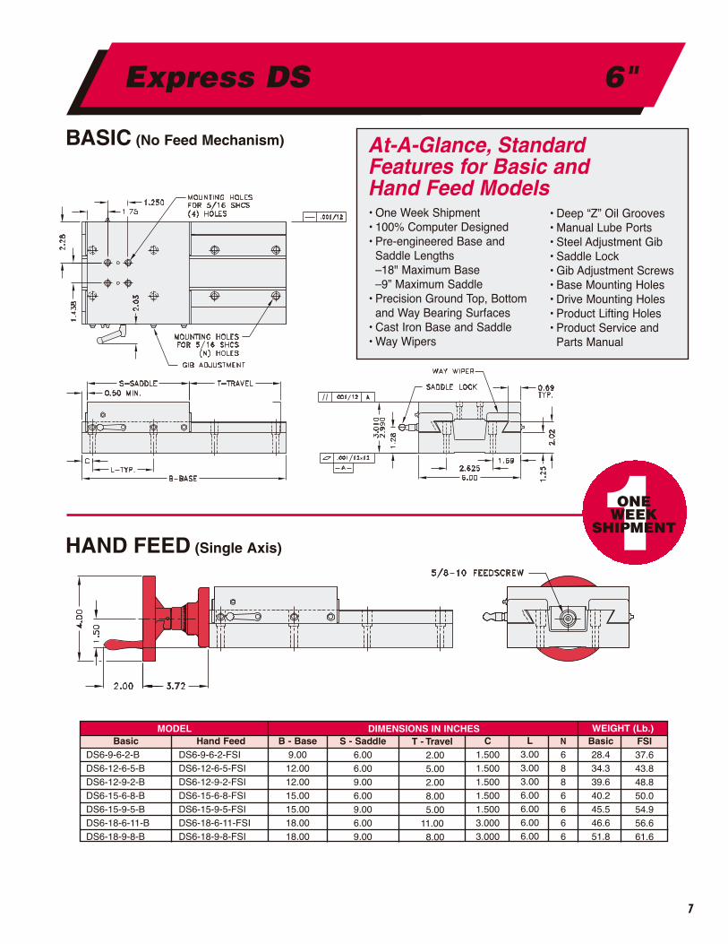
BASIC (No Feed Mechanism)
HAND FEED (Single Axis)
Express DS 6"
MODEL DIMENSIONS IN INCHES WEIGHT (Lb.)Basic
DS6-9-6-2-BDS6-12-6-5-BDS6-12-9-2-BDS6-15-6-8-BDS6-15-9-5-BDS6-18-6-11-BDS6-18-9-8-B
Hand FeedDS6-9-6-2-FSIDS6-12-6-5-FSIDS6-12-9-2-FSIDS6-15-6-8-FSIDS6-15-9-5-FSIDS6-18-6-11-FSIDS6-18-9-8-FSI
B - Base9.0012.0012.0015.0015.0018.0018.00
S - Saddle6.006.009.006.009.006.009.00
T - Travel2.005.002.008.005.00
11.008.00
C1.5001.5001.5001.5001.5003.0003.000
L3.003.003.006.006.006.006.00
N
6886666
Basic28.434.339.640.245.546.651.8
FSI37.643.848.850.054.956.661.6
• Deep “Z” Oil Grooves• Manual Lube Ports• Steel Adjustment Gib• Saddle Lock• Gib Adjustment Screws• Base Mounting Holes• Drive Mounting Holes• Product Lifting Holes• Product Service and
Parts Manual
At-A-Glance, StandardFeatures for Basic and Hand Feed Models• One Week Shipment• 100% Computer Designed • Pre-engineered Base and
Saddle Lengths –18" Maximum Base–9” Maximum Saddle
• Precision Ground Top, Bottom and Way Bearing Surfaces
• Cast Iron Base and Saddle• Way Wipers
1ONE WEEK
SHIPMENT
8
BASIC (No Feed Mechanism)
HAND FEED (Single Axis)
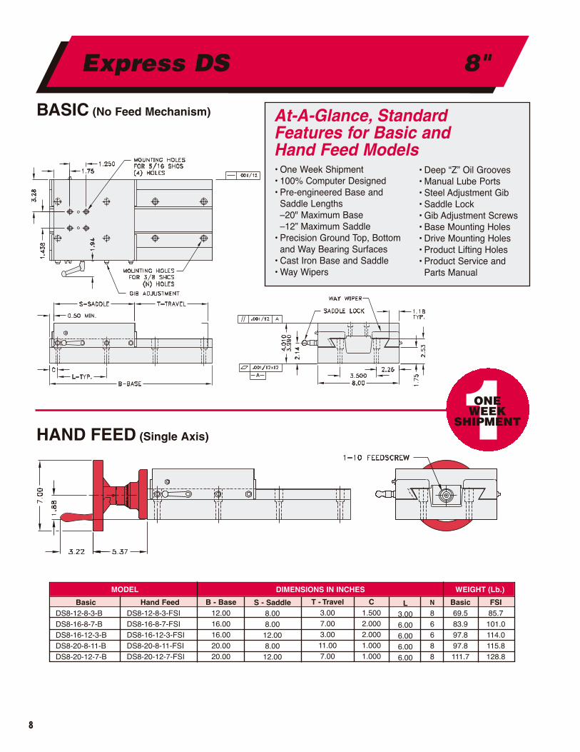
MODEL DIMENSIONS IN INCHES WEIGHT (Lb.)
C1.5002.0002.0001.0001.000
L3.006.006.006.006.00
N
86688
Basic69.583.997.897.8111.7
FSI85.7101.0114.0115.8128.8
Hand FeedDS8-12-8-3-FSIDS8-16-8-7-FSIDS8-16-12-3-FSIDS8-20-8-11-FSIDS8-20-12-7-FSI
B - Base12.0016.0016.0020.0020.00
S - Saddle8.008.0012.008.0012.00
T - Travel3.007.003.0011.007.00
BasicDS8-12-8-3-BDS8-16-8-7-BDS8-16-12-3-BDS8-20-8-11-BDS8-20-12-7-B
• Deep “Z” Oil Grooves• Manual Lube Ports• Steel Adjustment Gib• Saddle Lock• Gib Adjustment Screws• Base Mounting Holes• Drive Mounting Holes• Product Lifting Holes• Product Service and
Parts Manual
At-A-Glance, Standard Features for Basic and Hand Feed Models• One Week Shipment• 100% Computer Designed • Pre-engineered Base and
Saddle Lengths –20" Maximum Base–12” Maximum Saddle
• Precision Ground Top, Bottom and Way Bearing Surfaces
• Cast Iron Base and Saddle• Way Wipers
1ONE WEEK
SHIPMENT
Express DS 8"

9
BASIC (No Feed Mechanism)
HAND FEED (Single Axis)
• Deep “Z” Oil Grooves• Manual Lube Ports• Steel Adjustment Gib• Saddle Lock• Gib Adjustment Screws• Base Mounting Holes• Drive Mounting Holes• Product Lifting Holes• Product Service and
Parts Manual
At-A-Glance, Standard Features for Basic and Hand Feed Models• One Week Shipment• 100% Computer Designed • Pre-engineered Base and
Saddle Lengths –20" Maximum Base–10” Saddle
• Precision Ground Top, Bottom and Way Bearing Surfaces
• Cast Iron Base and Saddle• Way Wipers
1ONE WEEK
SHIPMENT
Express DS 10"
MODEL DIMENSIONS IN INCHES WEIGHT (Lb.)
Basic Hand Feed B-Base S-Saddle T-Travel C L N Basic FSI
DS10-15-10-4-B DS10-15-10-4-FSI 15.00 10.00 4.00 1.500 6.00 6 137.5 160.0
DS10-20-10-9-B DS10-20-10-9-FSI 20.00 10.00 9.00 1.000 6.00 8 165.7 189.0
10
BASIC (No Feed Mechanism)
HAND FEED (Single Axis)
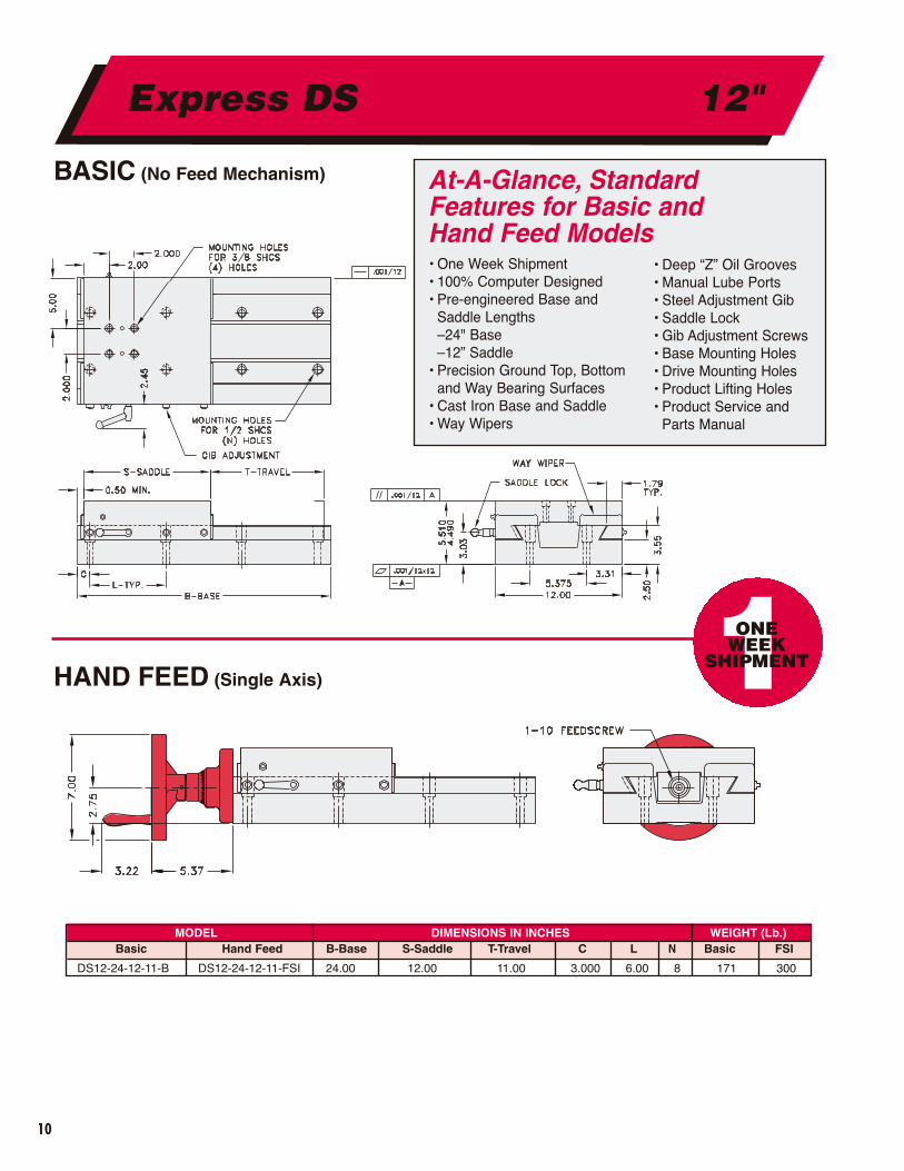
• Deep “Z” Oil Grooves• Manual Lube Ports• Steel Adjustment Gib• Saddle Lock• Gib Adjustment Screws• Base Mounting Holes• Drive Mounting Holes• Product Lifting Holes• Product Service and
Parts Manual
At-A-Glance, Standard Features for Basic and Hand Feed Models• One Week Shipment• 100% Computer Designed • Pre-engineered Base and
Saddle Lengths –24" Base–12” Saddle
• Precision Ground Top, Bottom and Way Bearing Surfaces
• Cast Iron Base and Saddle• Way Wipers
1ONE WEEK
SHIPMENT
Express DS 12"
MODEL DIMENSIONS IN INCHES WEIGHT (Lb.)Basic Hand Feed B-Base S-Saddle T-Travel C L N Basic FSI
DS12-24-12-11-B DS12-24-12-11-FSI 24.00 12.00 11.00 3.000 6.00 8 171 300
11
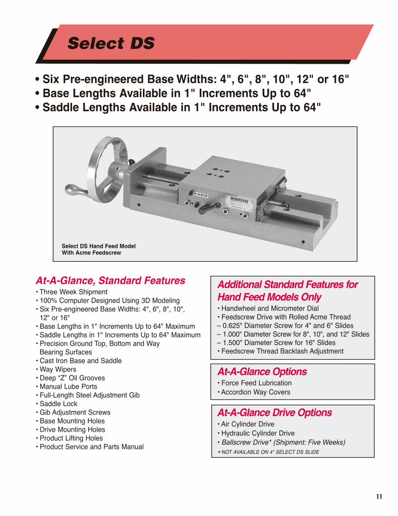
• Six Pre-engineered Base Widths: 4", 6", 8", 10", 12" or 16" • Base Lengths Available in 1" Increments Up to 64"• Saddle Lengths Available in 1" Increments Up to 64"
At-A-Glance, Standard Features • Three Week Shipment• 100% Computer Designed Using 3D Modeling• Six Pre-engineered Base Widths: 4", 6", 8", 10",
12" or 16" • Base Lengths in 1" Increments Up to 64" Maximum• Saddle Lengths in 1" Increments Up to 64" Maximum• Precision Ground Top, Bottom and Way
Bearing Surfaces• Cast Iron Base and Saddle• Way Wipers• Deep “Z” Oil Grooves• Manual Lube Ports• Full-Length Steel Adjustment Gib• Saddle Lock• Gib Adjustment Screws• Base Mounting Holes• Drive Mounting Holes• Product Lifting Holes• Product Service and Parts Manual
Additional Standard Features forHand Feed Models Only• Handwheel and Micrometer Dial• Feedscrew Drive with Rolled Acme Thread– 0.625" Diameter Screw for 4" and 6" Slides– 1.000" Diameter Screw for 8", 10", and 12" Slides– 1.500" Diameter Screw for 16" Slides• Feedscrew Thread Backlash Adjustment
At-A-Glance Options • Force Feed Lubrication• Accordion Way Covers
At-A-Glance Drive Options• Air Cylinder Drive• Hydraulic Cylinder Drive• Ballscrew Drive* (Shipment: Five Weeks)
* NOT AVAILABLE ON 4" SELECT DS SLIDE
Select DS Hand Feed Model With Acme Feedscrew
Select DS
12
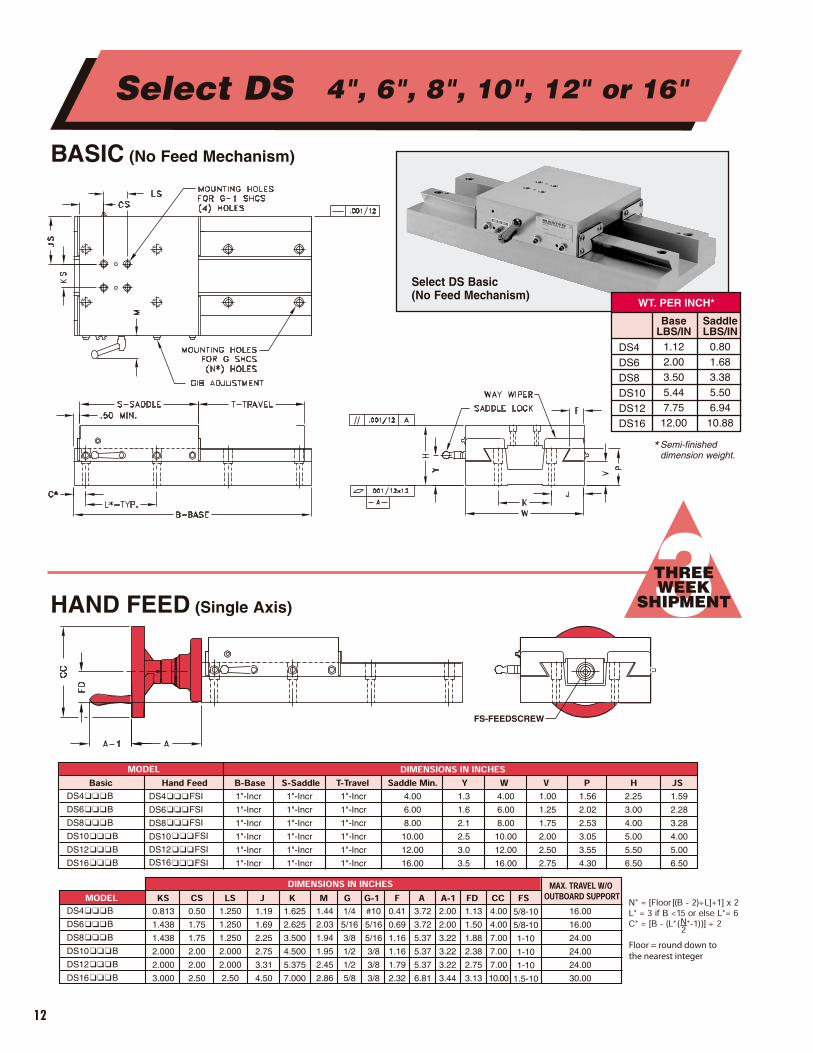
BASIC (No Feed Mechanism)
HAND FEED (Single Axis) 3THREE WEEK
SHIPMENT
Select DS 4", 6", 8", 10", 12" or 16"
Select DS Basic(No Feed Mechanism)
WT. PER INCH*
DS4DS6DS8DS10DS12DS16
* Semi-finished dimension weight.
BaseLBS/IN
1.122.003.505.447.7512.00
SaddleLBS/IN
0.801.683.385.506.9410.88
13
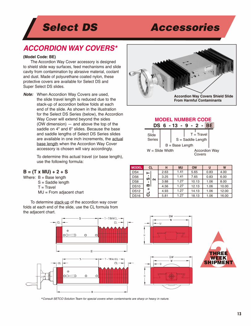
ACCORDION WAY COVERS*(Model Code: BE)
The Accordion Way Cover accessory is designed to shield slide way surfaces, feed mechanisms and slidecavity from contamination by abrasive material, coolantand dust. Made of polyurethane coated nylon, these protective covers are available for Select DS and Super Select DS slides.
Note: When Accordion Way Covers are used, the slide travel length is reduced due to thestack-up of accordion bellow folds at each end of the slide. As shown in the illustration for the Select DS Series (below), the AccordionWay Cover will extend beyond the sides (OW dimension) — and above the top of thesaddle on 4" and 6" slides. Because the baseand saddle lengths of Select DS Series slidesare available in one inch increments, the actualbase length when the Accordion Way Coveraccessory is chosen will vary accordingly.
To determine this actual travel (or base length),use the following formula:
B = (T x MU) + 2 + SWhere: B = Base length
S = Saddle lengthT = TravelMU = From adjacent chart
To determine stack-up of the accordion way coverfolds at each end of the slide, use the CL formula fromthe adjacent chart.
3THREE WEEK
SHIPMENT
Select DS Accessories
Accordion Way Covers Shield SlideFrom Harmful Contaminants
Slide Series
W = Slide Width
S = Saddle Length
B = Base Length
T = Travel
Accordion WayCovers
MODEL CL H MU OW U WDS4DS6DS8DS10DS12DS16 CL
= B
- S
- T
2
2.633.253.884.564.935.81
1.411.411.271.271.271.27
5.657.6510.1312.1314.1318.13
0.830.831.061.061.061.06
4.006.008.0010.0012.0016.00
*Consult SETCO Solution Team for special covers when contaminants are sharp or heavy in nature.
MODEL NUMBER CODEDS 6 - 13 - 9 - 2 - BE

14
MODEL METRIC DIMENSIONS IN INCHES METRIC MAX. TRAVEL W/OOUTBOARD SUPPORTBasic DR FL RL PR Key Ballscrew
DS4���FGM
DS6���FGM
DS8���FGM
DS10���FGM
DS12���FGM
DS16���FGM
N/A
10MM
10MM
12MM
12MM
25MM
N/A
0.98
0.98
1.38
1.38
1.57
N/A
1.34
1.34
2.61
2.61
3.01
N/A
2.34
2.34
4.55
4.55
5.07
N/A
3MM X 16MM
3MM X 16MM
4MM X 16MM
4MM X 16MM
8MM X 25MM
N/A
16MM X 5MM RH
16MM X 5MM RH
25MM X 5MM RH
25MM X 5MM RH
40MM X 10MM RH
N/A
16.0
16.0
24.0
24.030.0
PRECISION GROUND THREADBALLSCREW*(Model Code: FGM)
A Precision Ground Thread Ballscrew package with integral preloaded single ballnut is recommended for applications where:
• Optimum positioning accuracy and repeatability are required.
• Backlash cannot be tolerated.• Optimum stiffness and smooth,
linear motion are required.The lead accuracy of the precision ballscrew is within
0.0005 in./ft. cumulative, with the integral preloaded single ballnut providing zero backlash. The ballscrew is supported by a taper roller thrust bearing.
To protect the ballscrew from contaminants, optional accordion protectors are recommended.
Applications requiring long travels or high traverse rates may require an optional outboard support mounted on the endopposite the drive.
Notes: 1. For force and torque requirements, see page 49. 2. For optional drive packages, see pages 20 and 21.
5FIVE WEEK
SHIPMENT
Select DS Accessories
Precision GroundThread Ballscrew
Slide Series
W = Slide Width
S = Saddle Length
B = Base Length
T = Travel
Ballscrew
MODEL NUMBER CODEDS 6 - 9 - 6 - 2 - FGM
*Covers are recommended for applications that involve contaminants. Consult the SETCO Solution Team for further assistance.

15
Air or Hydraulic Cylinder Drive
Positive Stop Rod
AIR OR HYDRAULIC CYLINDER DRIVES(Air Cylinder Model Code: ASR)(Hydraulic Cylinder Model Code: HSR)
The Air Cylinder Drive accessory is designed with a 200 psi endurance rating and a cushioned cap end. This type of DS slide offers an economical and virtually maintenance-free system. It operates on dry, clean shopair, and is commonly used for light applications that do not require fine control of feedrate, or multiple positionapplications.
The Hydraulic Cylinder Drive accessory is designedwith a 500 psi endurance rating and a cushioned cap end.This type of DS slide is used for heavier load applicationsthat require fine feed control or multiple feeding.
Included as standard with either the Air or HydraulicCylinder accessory packages is an adjustable positive stop mounted alongside the cylinder. Way wipers are also included.
3THREE WEEK
SHIPMENT
Select DS Accessories
DIMENSIONS IN INCHESMODEL W R CL CB FD PR RL STOP ROD
DS4���HSR
DS6���HSR
DS8���HSR
DS10���HSR
DS12���HSR
DS16���HSR
4.00
6.00
8.00
10.00
12.00
16.00
1.56
2.06
2.25
2.81
3.06
3.56
1.00
1.00
1.00
1.00
1.00
1.00
1.50
2.00
2.50
3.25
4.00
5.00
1.13
1.69
2.06
2.38
2.75
3.13
1.13
1.25
1.38
1.44
1.63
1.75
4.25
3.93
4.06
4.63
4.63
4.94
0.375
0.50
0.50
0.75
0.75
1.00
Slide Series
W = Slide Width
S = Saddle Length
B = Base Length
T = Travel
Air Cylinder Drive orHydraulic CylinderDrive
MODEL NUMBER CODEDS 6 - 9 - 6 - 2 - ASR or HSR
16
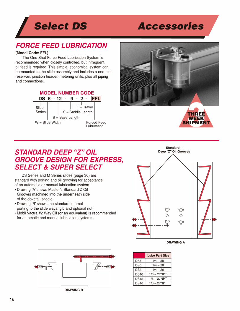
FORCE FEED LUBRICATION(Model Code: FFL)
The One Shot Force Feed Lubrication System is recommended when closely controlled, but infrequent, oil feed is required. This simple, economical system can be mounted to the slide assembly and includes a one pintreservoir, junction header, metering units, plus all pipingand connections.
DRAWING A
DRAWING B
Standard –Deep “Z” Oil Grooves
3THREE WEEK
SHIPMENT
Select DS Accessories
STANDARD DEEP “Z” OILGROOVE DESIGN FOR EXPRESS,SELECT & SUPER SELECT
DS Series and M Series slides (page 30) are standard with porting and oil grooving for acceptance of an automatic or manual lubrication system. • Drawing ‘A’ shows Master’s Standard Z Oil
Grooves machined into the underneath side of the dovetail saddle.
• Drawing ‘B’ shows the standard internal porting to the slide ways, gib and optional nut.
• Mobil Vactra #2 Way Oil (or an equivalent) is recommended for automatic and manual lubrication systems.
Slide Series
W = Slide Width
S = Saddle Length
B = Base Length
T = Travel
Forced FeedLubrication
MODEL NUMBER CODEDS 6 - 12 - 9 - 2 - FFL
1/4 – 281/4 – 281/4 – 28
1/8 – 27NPT1/8 – 27NPT1/8 – 27NPT
DS4DS6DS8DS10DS12DS16
Lube Part Size
17
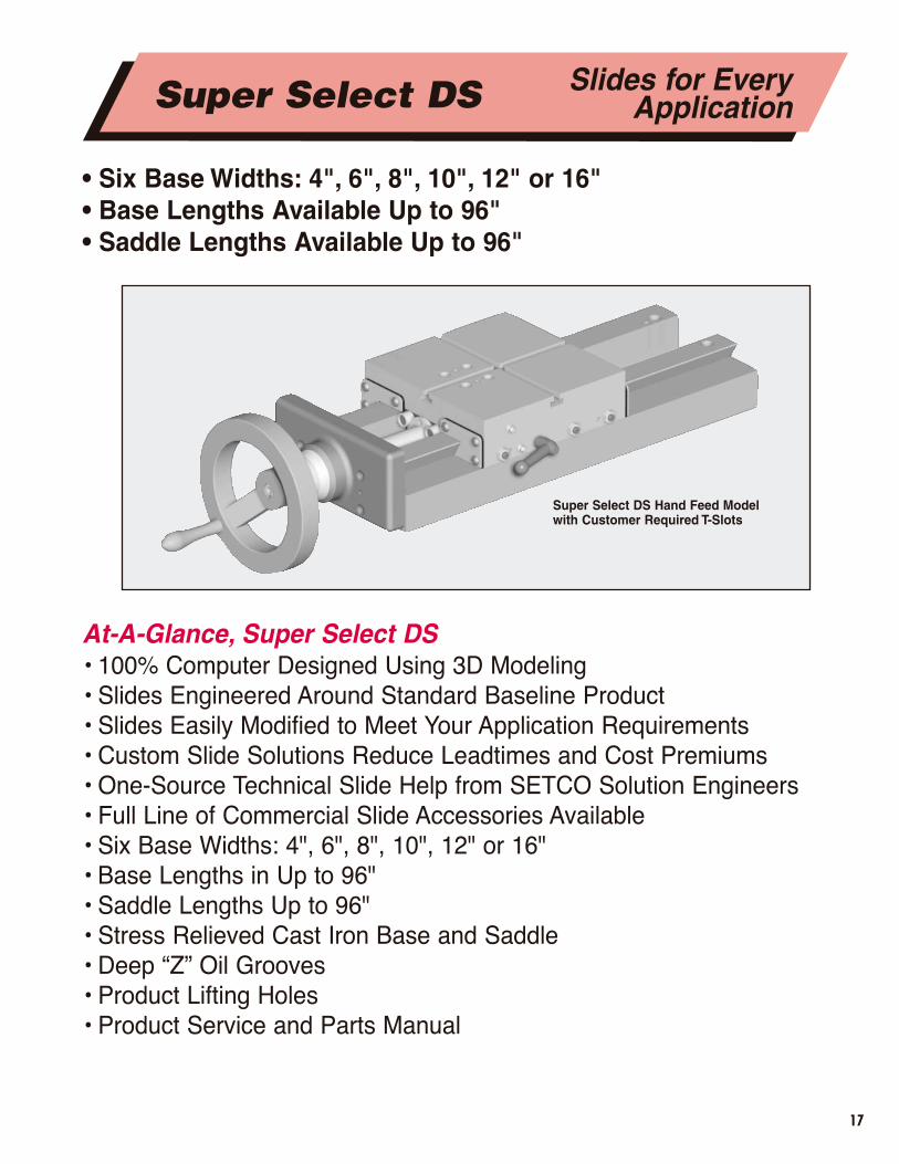
• Six Base Widths: 4", 6", 8", 10", 12" or 16" • Base Lengths Available Up to 96"• Saddle Lengths Available Up to 96"
At-A-Glance, Super Select DS • 100% Computer Designed Using 3D Modeling• Slides Engineered Around Standard Baseline Product• Slides Easily Modified to Meet Your Application Requirements• Custom Slide Solutions Reduce Leadtimes and Cost Premiums• One-Source Technical Slide Help from SETCO Solution Engineers• Full Line of Commercial Slide Accessories Available• Six Base Widths: 4", 6", 8", 10", 12" or 16" • Base Lengths in Up to 96"• Saddle Lengths Up to 96"• Stress Relieved Cast Iron Base and Saddle• Deep “Z” Oil Grooves• Product Lifting Holes• Product Service and Parts Manual
Super Select DS Hand Feed Model with Customer Required T-Slots
Super Select DS Slides for EveryApplication

18
This Super Select Slide is equiped with DoubleSaddles, each with Machined Keyways, and thePrecision Ballscrew package
No Drive (B)Acme Rolled Thread Feedscrew with Handwheel (FSI)Right Angle Hand Feed (RAF)Ratchet Handle Hand Feed (RH) Precision Ground Ballscrew (FGM) Belt Drive Package (U) Direct Coupled Drive Package (M) Air Cylinder Packages (ASR) Hydraulic Cylinder Packages (HSR) � Servo Cylinder Drive� Air/Oil Tandem Feed and Rapid Cycle� Air Cylinder with Controlled Feed Cycle� Special Ballscrew
Accordion Way Covers (BE)Metal Clad Protectors (H) Low-Friction Material (T) Force Feed Lubrication (FFL) Automatic Lubrication (A) Positive Stop (Q) Limit Switches • (2) End Travel (E) • (3) Travel < Saddle Length (F) • (3) Travel > Saddle Length (G)Vertical Angle Plate (P) Tapered Gib (X) Drilling (D) Keyway (K) T-Slot (S) Special Limit Switches� Special Tracking Tolerances� Compound Slide
SLIDE SERIES WIDTH BASE LENGTH SADDLE LENGTH TRAVEL DRIVE ACCESSORIES
DS 6 9 6 2
W S T
B
� Consult Factory for Special Model Code.
This Super Select Compound Slide isequiped with optional Air Cylinder DrivePackage and special mounting holes
Super Select Model Code
HOW TO ORDER SLIDE
Super Select DS Slides for EveryApplication
19
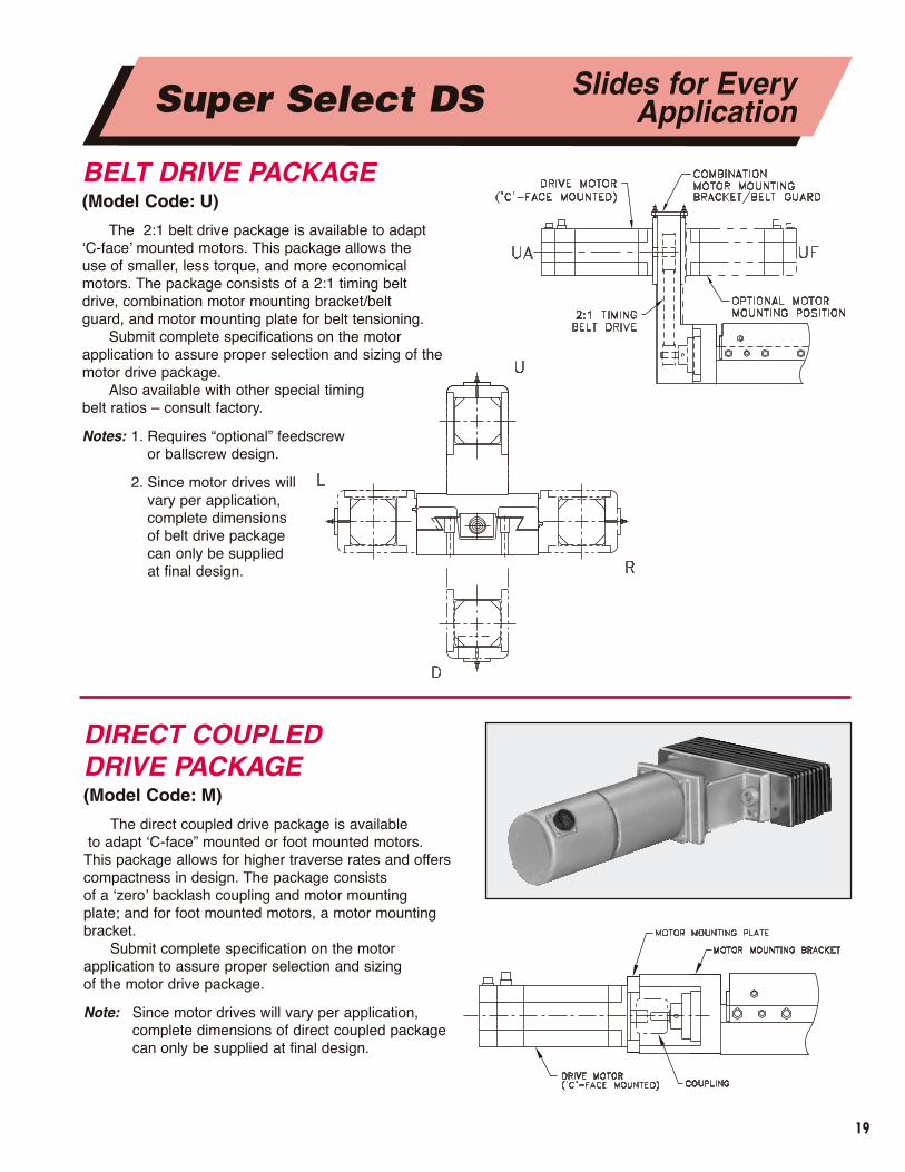
DIRECT COUPLED DRIVE PACKAGE(Model Code: M)
The direct coupled drive package is availableto adapt ‘C-face” mounted or foot mounted motors.
This package allows for higher traverse rates and offerscompactness in design. The package consists of a ‘zero’ backlash coupling and motor mounting plate; and for foot mounted motors, a motor mountingbracket.
Submit complete specification on the motor application to assure proper selection and sizing of the motor drive package.
Note: Since motor drives will vary per application,complete dimensions of direct coupled packagecan only be supplied at final design.
BELT DRIVE PACKAGE(Model Code: U)
The 2:1 belt drive package is available to adapt ‘C-face’ mounted motors. This package allows the use of smaller, less torque, and more economicalmotors. The package consists of a 2:1 timing belt drive, combination motor mounting bracket/belt guard, and motor mounting plate for belt tensioning.
Submit complete specifications on the motor application to assure proper selection and sizing of themotor drive package.
Also available with other special timing belt ratios – consult factory.
Notes: 1. Requires “optional” feedscrew or ballscrew design.
2. Since motor drives will vary per application, complete dimensions of belt drive package can only be supplied at final design.
Super Select DS Slides for EveryApplication
20
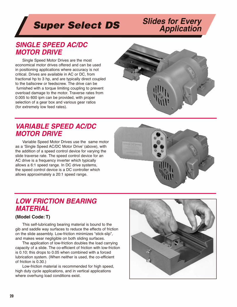
VARIABLE SPEED AC/DCMOTOR DRIVE
Variable Speed Motor Drives use the same motoras a ‘Single Speed AC/DC Motor Drive’ (above), withthe addition of a speed control device for varying theslide traverse rate. The speed control device for an AC drive is a frequency inverter which typically allows a 6:1 speed range. In DC drive systems, the speed control device is a DC controller whichallows approximately a 20:1 speed range.
SINGLE SPEED AC/DCMOTOR DRIVE
Single Speed Motor Drives are the most economical motor drives offered and can be used in positioning applications where accuracy is not critical. Drives are available in AC or DC, from fractional hp to 3 hp, and are typically direct coupledto the ballscrew or feedscrew. The drive can befurnished with a torque limiting coupling to prevent
overload damage to the motor. Traverse rates from0.005 to 600 ipm can be provided, with proper selection of a gear box and various gear ratios (for extremely low feed rates).
LOW FRICTION BEARING MATERIAL(Model Code: T)
This self-lubricating bearing material is bound to the gib and saddle way surfaces to reduce the effects of friction on the slide assembly. Low-friction minimizes “stick-slip”, and makes wear negligible on both sliding surfaces.
The application of low-friction doubles the load carryingcapacity of a slide. The co-efficient of friction with low-friction is 0.10; this drops to 0.05 when combined with a forced lubrication system. (When neither is used, the co-efficient of friction is 0.30.)
Low-friction material is recommended for high speed, high duty cycle applications, and in vertical applications where overhung load conditions exist.
Super Select DS Slides for EveryApplication
21
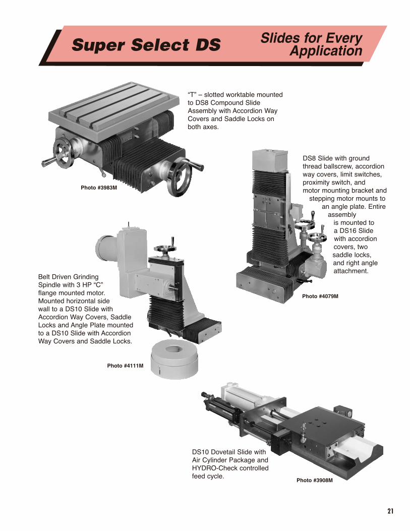
“T” – slotted worktable mountedto DS8 Compound SlideAssembly with Accordion WayCovers and Saddle Locks onboth axes.
DS8 Slide with groundthread ballscrew, accordionway covers, limit switches,proximity switch, and motor mounting bracket and
stepping motor mounts toan angle plate. Entire
assembly is mounted to a DS16 Slidewith accordioncovers, two saddle locks, and right angleattachment.
Belt Driven Grinding Spindle with 3 HP “C” flange mounted motor. Mounted horizontal side wall to a DS10 Slide withAccordion Way Covers, SaddleLocks and Angle Plate mountedto a DS10 Slide with AccordionWay Covers and Saddle Locks.
DS10 Dovetail Slide with Air Cylinder Package and HYDRO-Check controlled feed cycle.
Photo #3983M
Photo #4111M
Photo #3908M
Photo #4079M
Super Select DS Slides for EveryApplication
22
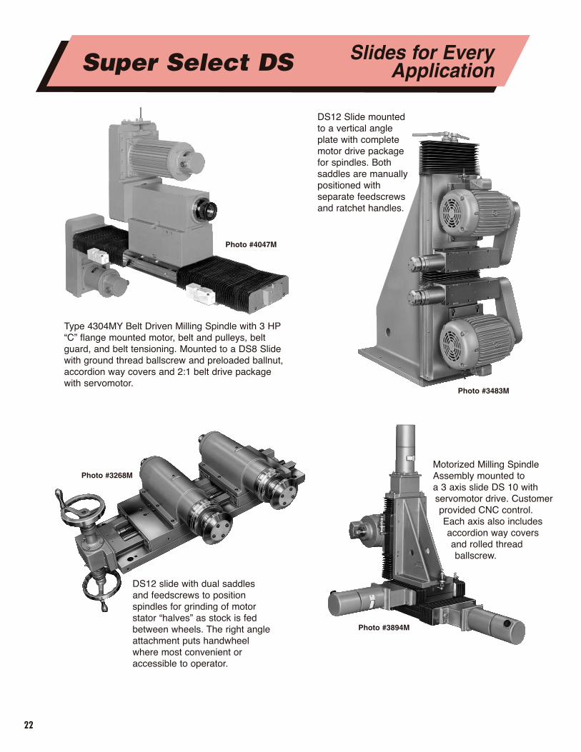
Type 4304MY Belt Driven Milling Spindle with 3 HP“C” flange mounted motor, belt and pulleys, beltguard, and belt tensioning. Mounted to a DS8 Slidewith ground thread ballscrew and preloaded ballnut,accordion way covers and 2:1 belt drive packagewith servomotor.
DS12 Slide mountedto a vertical angleplate with completemotor drive packagefor spindles. Bothsaddles are manuallypositioned withseparate feedscrewsand ratchet handles.
DS12 slide with dual saddlesand feedscrews to positionspindles for grinding of motorstator “halves” as stock is fedbetween wheels. The right angleattachment puts handwheelwhere most convenient oraccessible to operator.
Motorized Milling SpindleAssembly mounted to a 3 axis slide DS 10 withservomotor drive. Customerprovided CNC control.Each axis also includesaccordion way coversand rolled threadballscrew.
Super Select DS Slides for EveryApplication
Photo #3483M
Photo #3894M
Photo #3268M
Photo #4047M
23
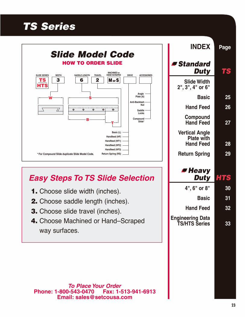
Slide Model Code
SLIDE SERIES WIDTH SADDLE LENGTH TRAVEL DRIVE ACCESSORIES
TSHTS
3 6 2
MACHINED orHAND SCRAPED
M or S
Angle Plate (A)
Anti-BacklashNut
SaddleLocks
CompoundSlide*
W S
TB
Basic (L)
Handfeed (HF)
Handfeed (HF1)
Handfeed (HF2)
Handfeed (HF3)
Return Spring (RS)* For Compound Slide duplicate Slide Model Code.
HOW TO ORDER SLIDE
INDEX Page
StandardDuty TS
Slide Width2", 3", 4" or 6"
Basic 25
Hand Feed 26
CompoundHand Feed 27
Vertical AnglePlate with
Hand Feed 28
Return Spring 29
HeavyDuty HTS
4", 6" or 8" 30
Basic 31
Hand Feed 32
Engineering Data TS/HTS Series 33
To Place Your OrderPhone: 1-800-543-0470 Fax: 1-513-941-6913
Email: [email protected]
Easy Steps To TS Slide Selection
1. Choose slide width (inches).
2. Choose saddle length (inches).
3. Choose slide travel (inches).4. Choose Machined or Hand–Scraped
way surfaces.
TS Series
24
TS Series
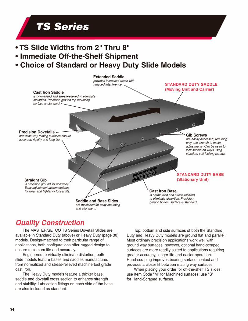
• TS Slide Widths from 2" Thru 8"• Immediate Off-the-Shelf Shipment• Choice of Standard or Heavy Duty Slide Models
Quality ConstructionThe MASTER/SETCO TS Series Dovetail Slides are
available in Standard Duty (above) or Heavy Duty (page 30)models. Design-matched to their particular range ofapplications, both configurations offer rugged design toensure maximum life and accuracy.
Engineered to virtually eliminate distortion, both slide models feature bases and saddles manufactured from normalized and stress-relieved machine tool gradecast iron.
The Heavy Duty models feature a thicker base, saddle and dovetail cross section to enhance strength and stability. Lubrication fittings on each side of the baseare also included as standard.
STANDARD DUTY SADDLE(Moving Unit and Carrier)
STANDARD DUTY BASE(Stationary Unit)
Top, bottom and side surfaces of both the StandardDuty and Heavy Duty models are ground flat and parallel.Most ordinary precision applications work well withground way surfaces, however, optional hand-scrapedsurfaces are more readily suited to applications requiringgreater accuracy, longer life and easier operation. Hand-scraping improves bearing surface contact and provides a closer fit between mating way surfaces.
When placing your order for off-the-shelf TS slides, use Item Code "M" for Machined surfaces; use "S" for Hand-Scraped surfaces.
Cast Iron Saddleis normalized and stress-relieved to eliminatedistortion. Precision-ground top mountingsurface is standard.
Precision Dovetailsand wide way mating surfaces ensureaccuracy, rigidity and long life.
Straight Gib is precision ground for accuracy.Easy adjustment accommodatesfor wear and tighter or looser fits.
Gib Screwsare easily accessed, requiringonly one wrench to makeadjustments. Can be used tolock saddle on ways using standard self-locking screws.
Cast Iron Baseis normalized and stress-relieved to eliminate distortion. Precision-ground bottom surface is standard.Saddle and Base Sides
are machined for easy mounting and alignment.
Extended Saddleprovides increased reach with reduced interference.
25
Standard Duty TS Series 2", 3", 4", or 6"
Width
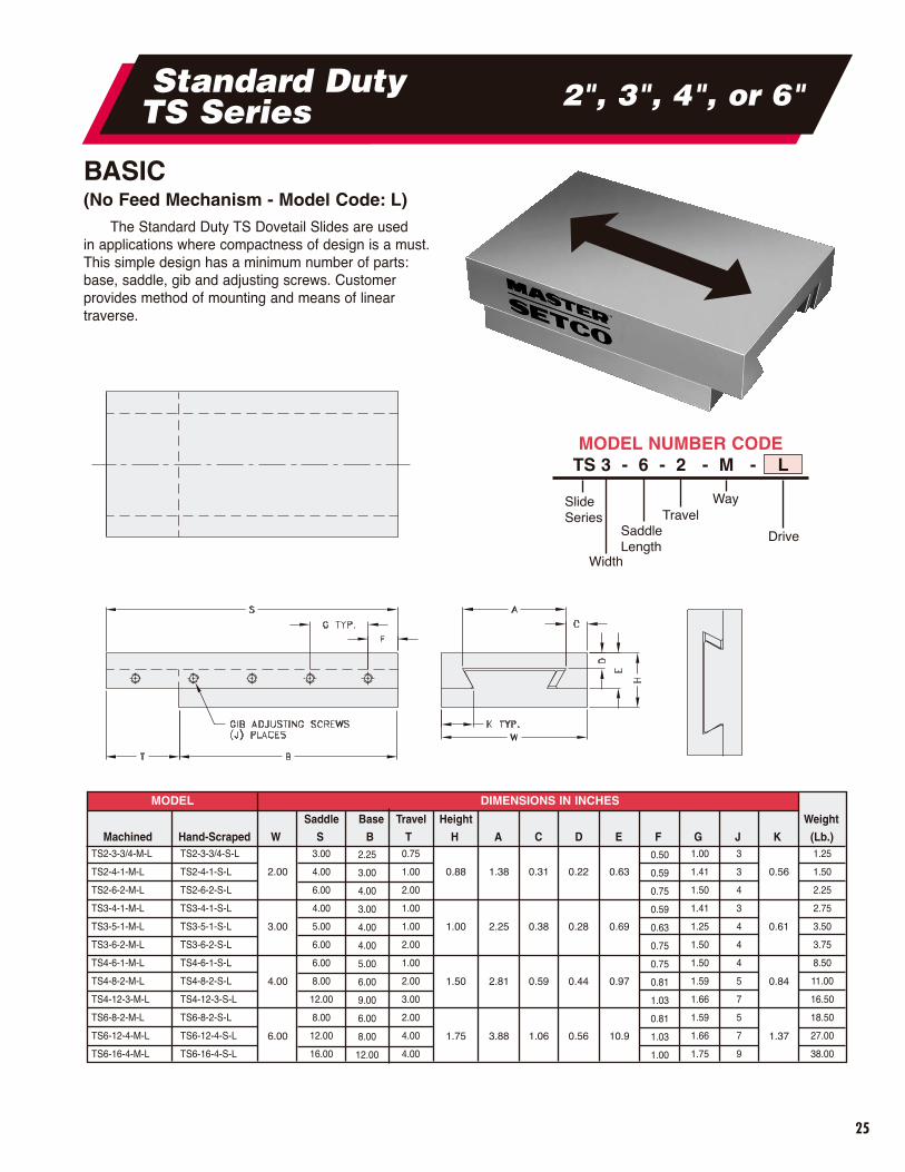
BASIC(No Feed Mechanism - Model Code: L)
The Standard Duty TS Dovetail Slides are used in applications where compactness of design is a must.This simple design has a minimum number of parts:base, saddle, gib and adjusting screws. Customer provides method of mounting and means of linear traverse.
MODEL DIMENSIONS IN INCHES
Machined Hand-Scraped
Saddle Base Travel Height Weight
W S B T H A C D E F G J K (Lb.)TS2-3-3/4-M-L
TS2-4-1-M-L
TS2-6-2-M-L
TS3-4-1-M-L
TS3-5-1-M-L
TS3-6-2-M-L
TS4-6-1-M-L
TS4-8-2-M-L
TS4-12-3-M-L
TS6-8-2-M-L
TS6-12-4-M-L
TS6-16-4-M-L
TS2-3-3/4-S-L
TS2-4-1-S-L
TS2-6-2-S-L
TS3-4-1-S-L
TS3-5-1-S-L
TS3-6-2-S-L
TS4-6-1-S-L
TS4-8-2-S-L
TS4-12-3-S-L
TS6-8-2-S-L
TS6-12-4-S-L
TS6-16-4-S-L
2.00
3.00
4.00
6.00
0.88
1.00
1.50
1.75
1.38
2.25
2.81
3.88
0.31
0.38
0.59
1.06
0.22
0.28
0.44
0.56
0.63
0.69
0.97
10.9
0.56
0.61
0.84
1.37
3.00
4.00
6.00
4.00
5.00
6.00
6.00
8.00
12.00
8.00
12.00
16.00
0.75
1.00
2.00
1.00
1.00
2.00
1.00
2.00
3.00
2.00
4.00
4.00
1.00
1.41
1.50
1.41
1.25
1.50
1.50
1.59
1.66
1.59
1.66
1.75
3
3
4
3
4
4
4
5
7
5
7
9
1.25
1.50
2.25
2.75
3.50
3.75
8.50
11.00
16.50
18.50
27.00
38.00
2.25
3.00
4.00
3.00
4.00
4.00
5.00
6.00
9.00
6.00
8.00
12.00
0.50
0.59
0.75
0.59
0.63
0.75
0.75
0.81
1.03
0.81
1.03
1.00
Slide Series Travel
SaddleLength
Way
Drive
MODEL NUMBER CODETS 3 - 6 - 2 - M - L

26
Standard Duty TS Series 2", 3", 4", or 6"
HAND FEED(Single Axis Model Code: HF)
The Standard Duty TS Dovetail Slides with HandFeed are used in applications requiring accuratemanual feed or positioning. Smooth feed movement is achieved through a V threaded leadscrew and amicrometer dial graduated in 0.001" increments. AnAcme threaded leadscrew, as noted by an asterisk (*) inthe chart below, can be supplied at extra cost on ModelsTS4 and TS6.
Standard Duty Hand Feed models include a BallCrank (HF 1, below). If space is limited, a Knurled Knob(HF 2) can be supplied. A Stub Shaft (HF 3) without a BallCrank or Knob is available on request for applicationswhere the customer’s drive system is used.
MODEL DIMENSIONS IN INCHES
Machined Hand-ScrapedSaddle Base Travel Height Weight
W S B T H A C D E F G R (Lb.)
2.00
3.00
4.00
6.00
0.88
1.00
1.50
1.75
2.81
2.81
3.69
4.41
1.25
1.25
1.50
1.75
0.312
0.312
0.375
0.500
0.88
0.88
1.56
1.88
0.35
0.38
0.63
0.69
3.00
4.00
6.00
4.00
5.00
6.00
6.00
8.00
12.00
8.00
12.00
16.00
0.75
1.00
2.00
1.00
1.00
2.00
1.00
2.00
3.00
2.00
4.00
4.00
1.75
2.00
2.75
3.25
4.00
4.25
9.50
12.00
17.50
21.25
29.50
40.00
2.25
3.00
4.00
3.00
4.00
4.00
5.00
6.00
9.00
6.00
8.00
12.00
1.59
1.59
2.31
2.75
5/16-40“V”
5/16-40“V”
1/2-20“V”or
*1/2-10ACME5/8-20
“V”or
*5/8-10ACME
Style HF 3 Style HF 2 Style HF 1
Slide Series Travel
Way
Drive
Width
MODEL NUMBER CODETS 3 - 6 - 2 - M - HF1
Saddle
TS2-3-3/4-M-HF�
TS2-4-1-M-HF�
TS2-6-2-M-HF�
TS3-4-1-M-HF�
TS3-5-1-M-HF�
TS3-6-2-M-HF�
TS4-6-1-M-HF�
TS4-8-2-M-HF�
TS4-12-3-M-HF�
TS6-8-2-M-HF�
TS6-12-4-M-HF�
TS6-16-4-M-HF�
TS2-3-3/4-S-HF�
TS2-4-1-S-HF�
TS2-6-2-S-HF�
TS3-4-1-S-HF�
TS3-5-1-S-HF�
TS3-6-2-S-HF�
TS4-6-1-S-HF�
TS4-8-2-S-HF�
TS4-12-3-S-HF�
TS6-8-2-S-HF�
TS6-12-4-S-HF�
TS6-16-4-S-HF�
� = HF 1, 2, or 3

*
MODEL DIMENSIONS IN INCHESSaddle Travel Saddle Travel Height Weight
Machined Hand-Scraped XW YW XS XT XK YS YT YK H HH A B C D E F G (Lb.)
TS2-6-2-M-HF/TS2-3-3/4-M-HF
TS2-4-1-M-HF/TS2-4-1-M-HF
TS3-6-2-M-HF/TS2-6-2-M-HF
TS3-6-2-M-HF/TS3-4-1-M-HF
TS3-5-1-M-HF/TS3-5-1-M-HF
TS4-12-3-M-HF/TS3-6-2-M-HF
TS4-12-3-M-HF/TS4-6-1-M-HF
TS4-8-2-M-HF/TS4-8-2-M-HF
TS6-12-4-M-HF/TS4-12-3-M-HF
TS6-12-4-M-HF/TS6-8-2-M-HF
TS6-12-4-M-HF/TS6-12-4-M-HF
HTS8-16-6-M-HF/TS6-16-4-M-HF
TS2-6-2-S-HF/TS2-3-3/4-S-HF
TS2-4-1-S-HF/TS2-4-1-S-HF
TS3-6-2-S-HF/TS2-6-2-S-HF
TS3-6-2-S-HF/TS3-4-1-S-HF
TS3-5-1-S-HF/TS3-5-1-S-HF
TS4-12-3-S-HF/TS3-6-2-S-HF
TS4-12-3-S-HF/TS4-6-1-S-HF
TS4-8-2-S-HF/TS4-8-2-S-HF
TS6-12-4-S-HF/TS4-12-3-S-HF
TS6-12-4-S-HF/TS6-8-2-S-HF
TS6-12-4-S-HF/TS6-12-4-S-HF
HTS8-16-6-S-HF/TS6-16-4-S-HF
2.00
2.00
3.00
3.00
3.00
4.00
4.00
4.00
6.00
6.00
6.00
8.00
2.00
3.00
4.00
6.00
6.00
4.00
6.00
6.00
5.00
12.00
12.00
8.00
12.00
12.00
12.00
16.00
2.00
1.00
2.00
2.00
1.00
3.00
3.00
2.00
4.00
4.00
4.00
6.00
8.81
6.81
8.81
8.81
7.81
15.69
15.69
11.69
16.41
16.41
16.41
20.38
3.00
4.00
6.00
4.00
5.00
6.00
6.00
8.00
12.00
8.00
12.00
16.00
0.75
1.00
2.00
1.00
1.00
2.00
1.00
2.00
3.00
2.00
4.00
4.00
5.81
6.81
8.81
6.81
7.81
8.81
9.69
11.69
15.69
12.41
16.41
20.41
0.88
0.88
1.00
1.00
1.00
1.50
1.50
1.50
1.75
1.75
1.75
2.75
1.75
1.75
1.88
2.00
2.00
2.50
3.00
3.00
3.25
3.50
3.50
4.50
0.12
0.50
0.50
0.00
0.50
0.00
0.50
1.00
1.50
0.00
1.00
2.00
2.00
1.00
2.00
1.50
1.00
4.50
4.00
2.00
4.00
3.00
3.00
5.00
0.25
0.25
0.38
0.38
0.38
0.63
0.63
0.63
0.75
0.75
0.75
2.50
2.75
1.75
3.25
3.25
3.25
7.75
7.75
4.75
6.50
6.50
6.50
5.00
0.69
0.69
0.94
0.94
0.94
1.38
1.38
1.38
1.88
1.88
1.88
2.75
0.44
0.4
1.12
1.12
1.12
1.12
1.25
1.25
2.25
2.25
2.25
2.5
#8
#8
#10
#10
#10
1/4
1/4
1/4
5/16
5/16
5/16
5/16
3.50
3.00
6.00
6.50
7.00
20.25
25.00
22.00
43.50
45.50
54.00
135.00
COMPOUND HAND FEEDThe versatile Standard Duty TS Dovetail Slides
can be used for applications requiring accurate 2-axis positioning or feeding. This isaccomplished by combining two standardleadscrew slide assemblies. These unitsare bolted together, aligned and doweled inposition at 90º to provide accurate, coordinatedX- and Y-axis movements.
Mounting holes are provided in thebase of the bottom slide unit for easyinstallation. Consult factory for availabilityof other assembly combinations.
* Standard on CompoundUnit Only.
TS 2 - 6 - 2 - M - HF / TS 2 - 3 - 3/4 - M - HF
Slide Series Travel
WayDrive
Width
SaddleLength
Slide Series Travel
WayDrive
Width
SaddleLength
MODEL NUMBER CODEBottom Slide (Shown in red) Top Slide
27
Standard Duty TS Series 2", 3", 4", or 6"
28
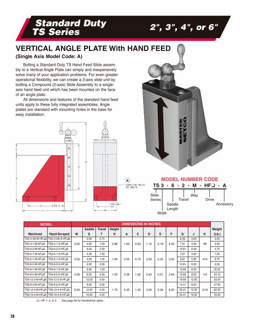
VERTICAL ANGLE PLATE With HAND FEED(Single Axis Model Code: A)
Bolting a Standard Duty TS Hand Feed Slide assem-bly to a Vertical Angle Plate can simply and inexpensivelysolve many of your application problems. For even greateroperational flexibility, we can create a 3-axis slide unit bybolting a Compound (2-axis) Slide Assembly to a single-axis hand feed unit which has been mounted on the faceof an angle plate.
All dimensions and features of the standard hand feedunits apply to these fully integrated assemblies. Angleplates are standard with mounting holes in the base foreasy installation.
MODEL DIMENSIONS IN INCHES
Machined Hand-ScrapedSaddle Travel Height Weight
W S T H A C D E F G J K (Lb.)TS2-3-3/4-M-HF�A
TS2-4-1-M-HF�A
TS2-6-2-M-HF�A
TS3-4-1-M-HF�A
TS3-5-1-M-HF�A
TS3-6-2-M-HF�A
TS4-6-1-M-HF�A
TS4-8-2-M-HF�A
TS4-12-3-M-HF�A
TS6-8-2-M-HF�A
TS6-12-4-M-HF�A
TS6-16-4-M-HF�A
TS2-3-3/4-S-HF�A
TS2-4-1-S-HF�A
TS2-6-2-S-HF�A
TS3-4-1-S-HF�A
TS3-5-1-S-HF�A
TS3-6-2-S-HF�A
TS4-6-1-S-HF�A
TS4-8-2-S-HF�A
TS4-12-3-S-HF�A
TS6-8-2-S-HF�A
TS6-12-4-S-HF�A
TS6-16-4-S-HF�A
2.00
3.00
4.00
6.00
0.88
1.00
1.50
1.75
1.63
2.50
3.38
5.25
0.63
0.75
1.00
1.25
1.12
2.00
2.63
4.25
0.19
0.25
0.31
0.38
2.00
3.00
4.00
6.00
#8
#10
1/4
5/16
3.00
4.00
6.00
4.00
5.00
6.00
6.00
8.00
12.00
8.00
12.00
16.00
0.75
1.00
2.00
1.00
1.00
2.00
1.00
2.00
3.00
2.00
4.00
4.00
6.56
7.81
10.81
7.81
8.81
10.81
10.69
13.69
18.69
14.41
20.41
24.41
3.00
4.00
6.00
4.00
5.00
6.00
6.00
8.00
12.00
8.00
12.00
16.00
3.00
3.50
4.75
7.00
8.75
9.50
20.25
24.75
33.50
47.00
62.00
78.00
K MODEL NUMBER CODETS 3 - 6 - 2 - M - HF� - A
Slide Series Travel
WayDrive
Width
SaddleLength
Accessory
Standard Duty TS Series 2", 3", 4", or 6"
� = HF 1, 2, or 3 See page 26 for handle/knob styles.
29
Standard Duty TS Series 2", 3", 4", or 6"
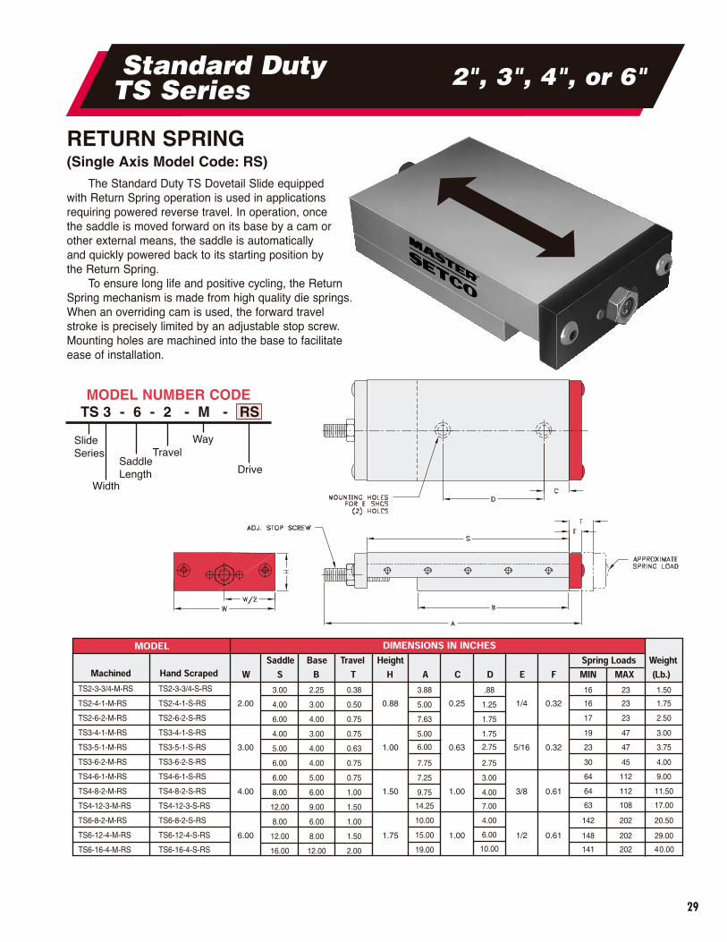
RETURN SPRING(Single Axis Model Code: RS)
The Standard Duty TS Dovetail Slide equippedwith Return Spring operation is used in applicationsrequiring powered reverse travel. In operation, oncethe saddle is moved forward on its base by a cam orother external means, the saddle is automaticallyand quickly powered back to its starting position bythe Return Spring.
To ensure long life and positive cycling, the ReturnSpring mechanism is made from high quality die springs.When an overriding cam is used, the forward travel stroke is precisely limited by an adjustable stop screw.Mounting holes are machined into the base to facilitate ease of installation.
Slide Series Travel
SaddleLength
Way
Drive
Width
MODEL NUMBER CODETS 3 - 6 - 2 - M - RS
30
Heavy Duty HTS Series
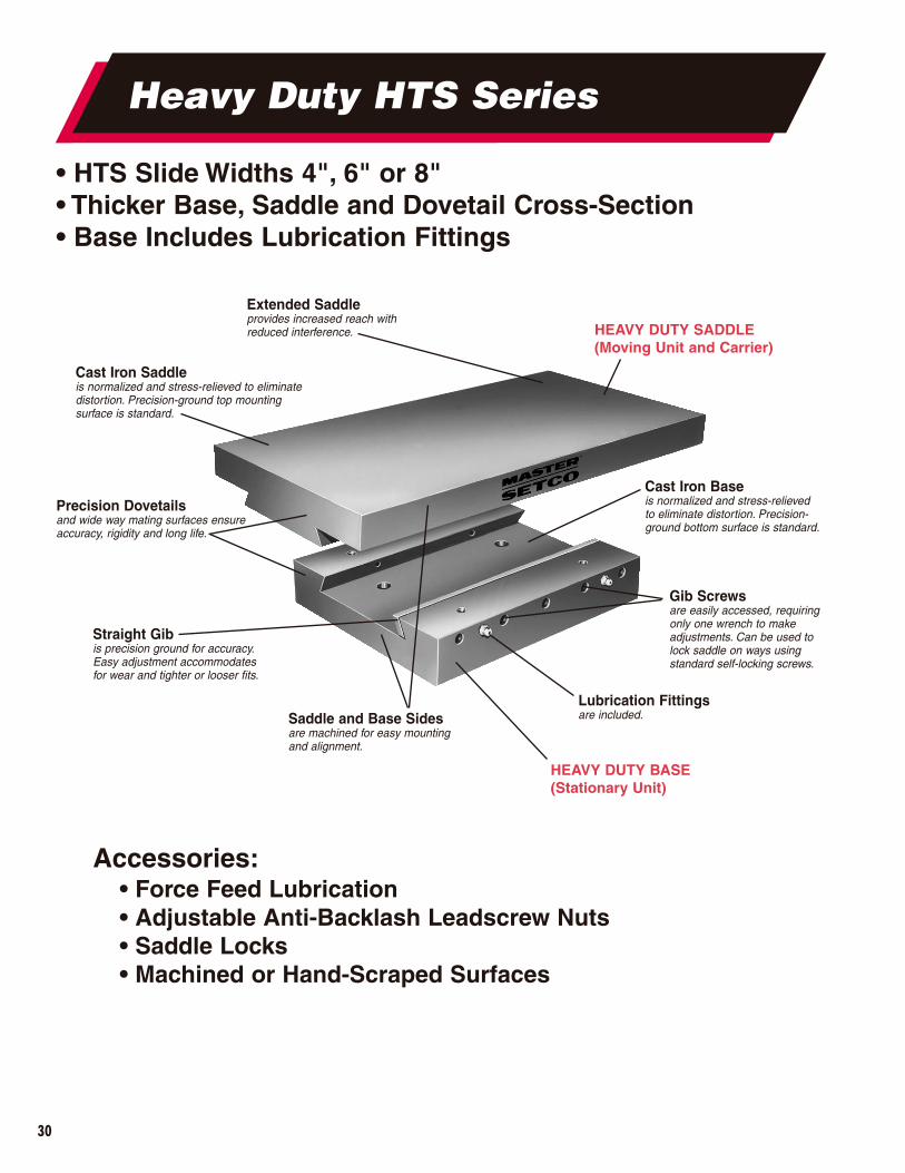
HEAVY DUTY SADDLE(Moving Unit and Carrier)
HEAVY DUTY BASE(Stationary Unit)
Cast Iron Saddleis normalized and stress-relieved to eliminatedistortion. Precision-ground top mounting surface is standard.
Precision Dovetailsand wide way mating surfaces ensureaccuracy, rigidity and long life.
Straight Gib is precision ground for accuracy.Easy adjustment accommodatesfor wear and tighter or looser fits.
Gib Screwsare easily accessed, requiringonly one wrench to makeadjustments. Can be used tolock saddle on ways using standard self-locking screws.
Cast Iron Baseis normalized and stress-relieved to eliminate distortion. Precision-ground bottom surface is standard.
Saddle and Base Sidesare machined for easy mounting and alignment.
• HTS Slide Widths 4", 6" or 8"• Thicker Base, Saddle and Dovetail Cross-Section• Base Includes Lubrication Fittings
Accessories:• Force Feed Lubrication• Adjustable Anti-Backlash Leadscrew Nuts• Saddle Locks• Machined or Hand-Scraped Surfaces
Lubrication Fittingsare included.
Extended Saddleprovides increased reach with reduced interference.
31
Heavy Duty HTS Series 4", 6" or 8"
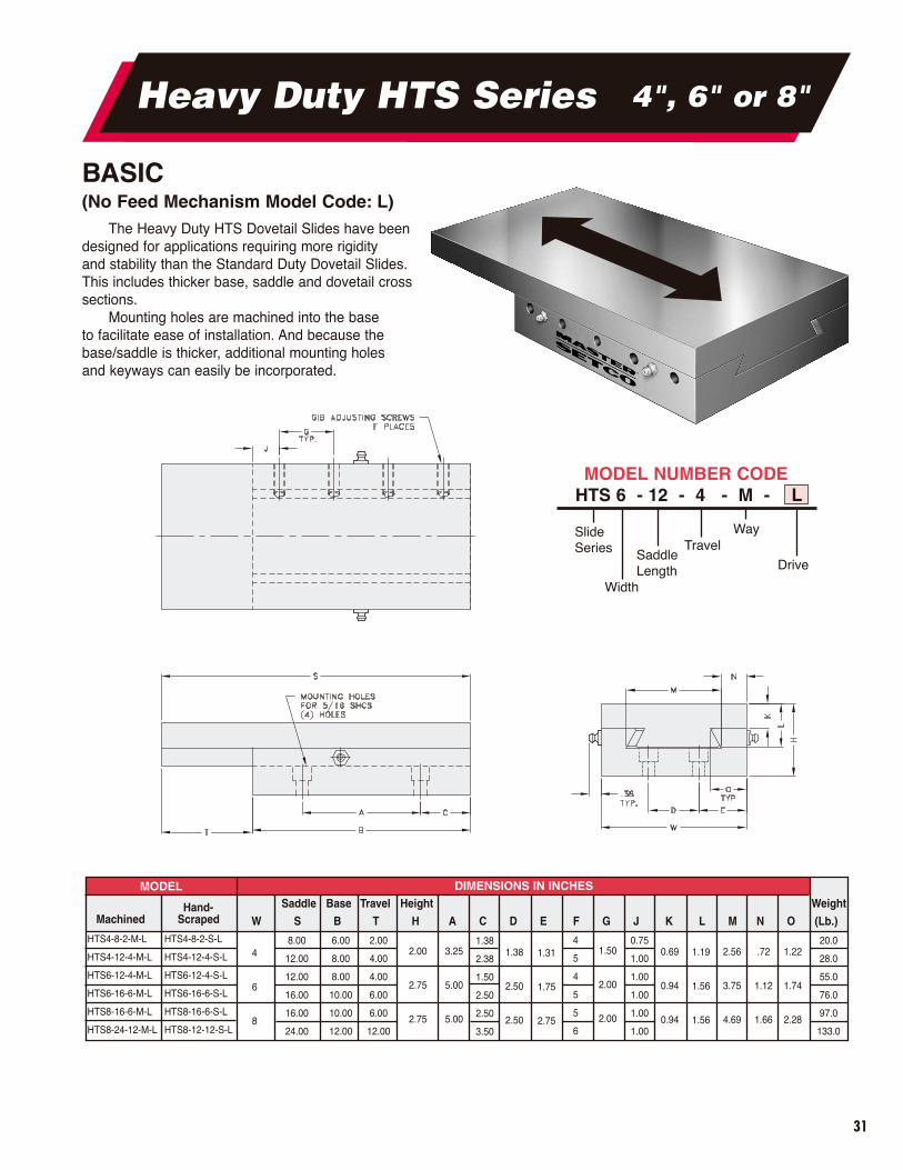
BASIC(No Feed Mechanism Model Code: L)
The Heavy Duty HTS Dovetail Slides have beendesigned for applications requiring more rigidity and stability than the Standard Duty Dovetail Slides.This includes thicker base, saddle and dovetail crosssections.
Mounting holes are machined into the base to facilitate ease of installation. And because thebase/saddle is thicker, additional mounting holes and keyways can easily be incorporated.
MODEL DIMENSIONS IN INCHES
Hand-Machined Scraped
Saddle Base Travel Height Weight
W S B T H A C D E F G J K L M N O (Lb.)HTS4-8-2-M-L
HTS4-12-4-M-L
HTS6-12-4-M-L
HTS6-16-6-M-L
HTS8-16-6-M-L
HTS8-24-12-M-L
8.00
12.00
12.00
16.00
16.00
24.00
HTS4-8-2-S-L
HTS4-12-4-S-L
HTS6-12-4-S-L
HTS6-16-6-S-L
HTS8-16-6-S-L
HTS8-12-12-S-L
6.00
8.00
8.00
10.00
10.00
12.00
2.00
4.00
4.00
6.00
6.00
12.00
4
5
4
5
5
6
0.75
1.00
1.00
1.00
1.00
1.00
20.0
28.0
55.0
76.0
97.0
133.0
4
6
8
2.00
2.75
2.75
3.25
5.00
5.00
1.38
2.38
1.50
2.50
2.50
3.50
1.38
2.50
2.50
1.31
1.75
2.75
1.50
2.00
2.00
0.69
0.94
0.94
1.19
1.56
1.56
2.56
3.75
4.69
.72
1.12
1.66
1.22
1.74
2.28
Slide Series Travel
SaddleLength
Way
Drive
Width
MODEL NUMBER CODEHTS 6 - 12 - 4 - M - L
32
Heavy Duty HTS Series 4", 6" or 8"
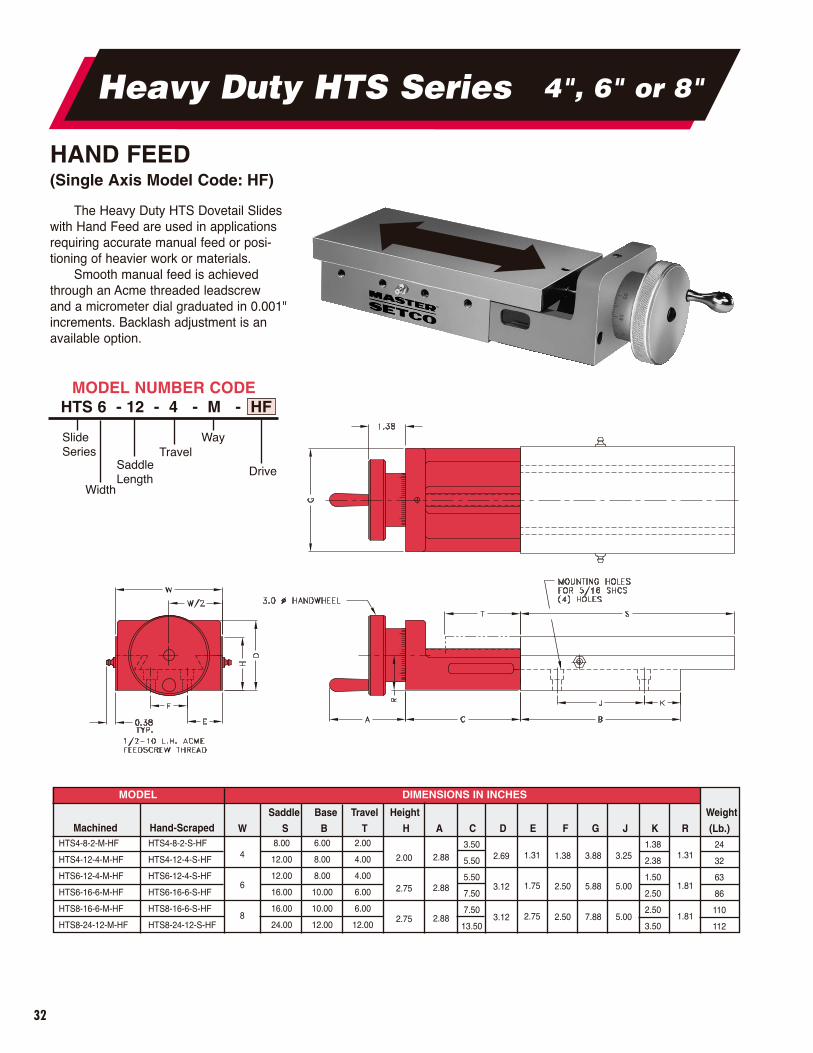
HAND FEED(Single Axis Model Code: HF)
The Heavy Duty HTS Dovetail Slideswith Hand Feed are used in applicationsrequiring accurate manual feed or posi-tioning of heavier work or materials.
Smooth manual feed is achievedthrough an Acme threaded leadscrewand a micrometer dial graduated in 0.001" increments. Backlash adjustment is anavailable option.
MODEL DIMENSIONS IN INCHES
Machined Hand-ScrapedSaddle Base Travel Height Weight
W S B T H A C D E F G J K R (Lb.)HTS4-8-2-M-HF
HTS4-12-4-M-HF
HTS6-12-4-M-HF
HTS6-16-6-M-HF
HTS8-16-6-M-HF
HTS8-24-12-M-HF
8.00
12.00
12.00
16.00
16.00
24.00
HTS4-8-2-S-HF
HTS4-12-4-S-HF
HTS6-12-4-S-HF
HTS6-16-6-S-HF
HTS8-16-6-S-HF
HTS8-24-12-S-HF
6.00
8.00
8.00
10.00
10.00
12.00
2.00
4.00
4.00
6.00
6.00
12.00
3.50
5.50
5.50
7.50
7.50
13.50
1.38
2.38
1.50
2.50
2.50
3.50
24
32
63
86
110
112
4
6
8
2.00
2.75
2.75
2.88
2.88
2.88
2.69
3.12
3.12
1.38
2.50
2.50
3.88
5.88
7.88
3.25
5.00
5.00
1.31
1.75
2.75
1.31
1.81
1.81
Slide Series Travel
SaddleLength
Way
Drive
Width
MODEL NUMBER CODEHTS 6 - 12 - 4 - M - HF
33
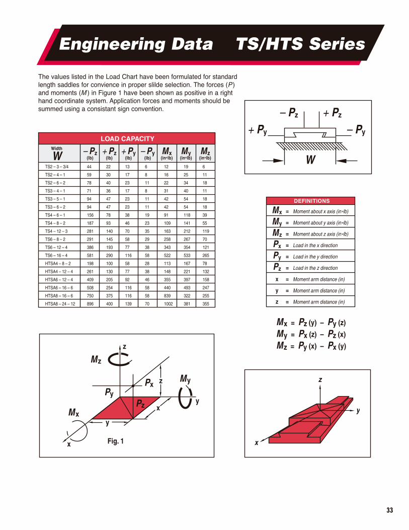
Engineering Data TS/HTS Series
The values listed in the Load Chart have been formulated for standardlength saddles for convience in proper slilde selection. The forces (P )and moments (M ) in Figure 1 have been shown as positive in a righthand coordinate system. Application forces and moments should besummed using a consistant sign convention.
Fig. 1x
y
x
z
y
z
Mz
Mx
My
PyPx
Pz
Mx = Pz (y) – Py (z)
My = Px (z) – Pz (x)
Mz = Py (x) – Px (y)
x
z
y
W
+ Py – Py
+ Pz– Pz
DEFINITIONS
Mx = Moment about x axis (in*lb)
My = Moment about y axis (in*lb)
Mz = Moment about z axis (in*lb)
Px = Load in the x direction
Py = Load in the y direction
Pz = Load in the z direction
x = Moment arm distance (in)
y = Moment arm distance (in)
z = Moment arm distance (in)
LOAD CAPACITY
TS2 – 3 – 3/4
TS2 – 4 – 1
TS2 – 6 – 2
TS3 – 4 – 1
TS3 – 5 – 1
TS3 – 6 – 2
TS4 – 6 – 1
TS4 – 8 – 2
TS4 – 12 – 3
TS6 – 8 – 2
TS6 – 12 – 4
TS6 – 16 – 4
HTSA4 – 8 – 2
HTSA4 – 12 – 4
HTSA6 – 12 – 4
HTSA6 – 16 – 6
HTSA8 – 16 – 6
HTSA8 – 24 – 12
44
59
78
71
94
94
156
187
281
291
386
581
198
261
409
508
750
896
22
30
40
36
47
47
78
93
140
145
193
290
100
130
205
254
375
400
13
17
23
17
23
23
38
46
70
58
77
116
58
77
92
116
116
139
6
8
11
8
11
11
19
23
35
29
38
58
28
38
46
58
58
70
12
16
22
31
42
42
91
109
163
258
343
522
113
148
355
440
839
1002
19
25
34
40
54
54
118
141
212
267
354
533
167
221
397
493
322
381
6
11
18
11
18
18
39
55
119
70
121
265
78
132
158
247
255
355
– Pz(lb)
+ Pz(lb)
+ Py(lb)
– Py(lb)
Mx(in*lb)
My(in*lb)
Mz(in*lb)
Width
W
34
M Series
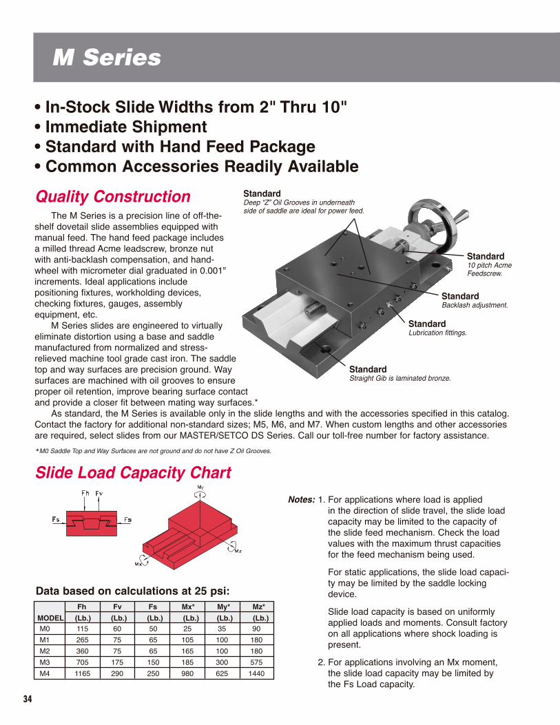
Quality ConstructionThe M Series is a precision line of off-the-
shelf dovetail slide assemblies equipped withmanual feed. The hand feed package includesa milled thread Acme leadscrew, bronze nutwith anti-backlash compensation, and hand-wheel with micrometer dial graduated in 0.001"increments. Ideal applications includepositioning fixtures, workholding devices,checking fixtures, gauges, assemblyequipment, etc.
M Series slides are engineered to virtuallyeliminate distortion using a base and saddlemanufactured from normalized and stress-relieved machine tool grade cast iron. The saddletop and way surfaces are precision ground. Waysurfaces are machined with oil grooves to ensureproper oil retention, improve bearing surface contactand provide a closer fit between mating way surfaces.*
As standard, the M Series is available only in the slide lengths and with the accessories specified in this catalog.Contact the factory for additional non-standard sizes; M5, M6, and M7. When custom lengths and other accessoriesare required, select slides from our MASTER/SETCO DS Series. Call our toll-free number for factory assistance.
*M0 Saddle Top and Way Surfaces are not ground and do not have Z Oil Grooves.
• In-Stock Slide Widths from 2" Thru 10"• Immediate Shipment• Standard with Hand Feed Package• Common Accessories Readily Available
StandardStraight Gib is laminated bronze.
StandardLubrication fittings.
StandardBacklash adjustment.
Standard10 pitch Acme Feedscrew.
StandardDeep “Z” Oil Grooves in underneathside of saddle are ideal for power feed.
Notes: 1. For applications where load is applied in the direction of slide travel, the slide loadcapacity may be limited to the capacity of the slide feed mechanism. Check the load values with the maximum thrust capacities for the feed mechanism being used.
For static applications, the slide load capaci-ty may be limited by the saddle lockingdevice.
Slide load capacity is based on uniformlyapplied loads and moments. Consult factoryon all applications where shock loading ispresent.
2. For applications involving an Mx moment, the slide load capacity may be limited by the Fs Load capacity.
Slide Load Capacity Chart
MODEL (Lb.) (Lb.) (Lb.) (Lb.) (Lb.) (Lb.)
Fh Fv Fs Mx* My* Mz*
M0
M1
M2
M3
M4
115
265
360
705
1165
60
75
75
175
290
50
65
65
150
250
25
105
165
185
980
35
100
100
300
625
90
180
180
575
1440
Data based on calculations at 25 psi:
35
At-A-Glance, M Series • Saddle–The moving member and carrier. Manufactured from fine grain
40,000 PSI tensile gray iron, stress relieved and properly normalized for minimal distortion. SADDLE top and way surfaces are precision ground, with way surfaces oil grooved and hand-flaked to ensure proper oil retention.
• Base–The stationary member. Manufactured from fine grain 40,000 PSI tensile gray iron, stress relieved and properly normalized for minimal distortion. BASE top and bottom are precision ground.
• Straight Gib–Adjustable member for setting slide clearances between saddle and ways. Manufactured from wear resistant laminated bronze. Way surfaces are precision ground, oil grooved and fitted to ensure long lasting operation.
• Gib Adjusting Screws–Socket set screws properly spaced along gib side of saddle for adjusting gib.
• Gib Screw Nuts–Hex jam nuts which lock the gib adjusting screws in place, maintaining gib adjustment.
• Gib Pin–Straight pin to retain linear positioning of gib.• Lubrication Fittings–For pressure gun lubrication. Can be removed for
manual or automatic systems. Mobil Vactra #2 way oil or equivalent is recommended.
INDEX Page
M SeriesSlide Width
Type M0: 2" 36
Type M1: 4" 37
Type M2: 6" 38
Type M3: 8" 39
Type M4: 10" 40
Accessories 41-45
Application Photos 46-47
Design DataDS/M Series 48-51
To Place Your OrderPhone: 1-800-543-0470 Fax: 1-513-941-6913
Email: [email protected]
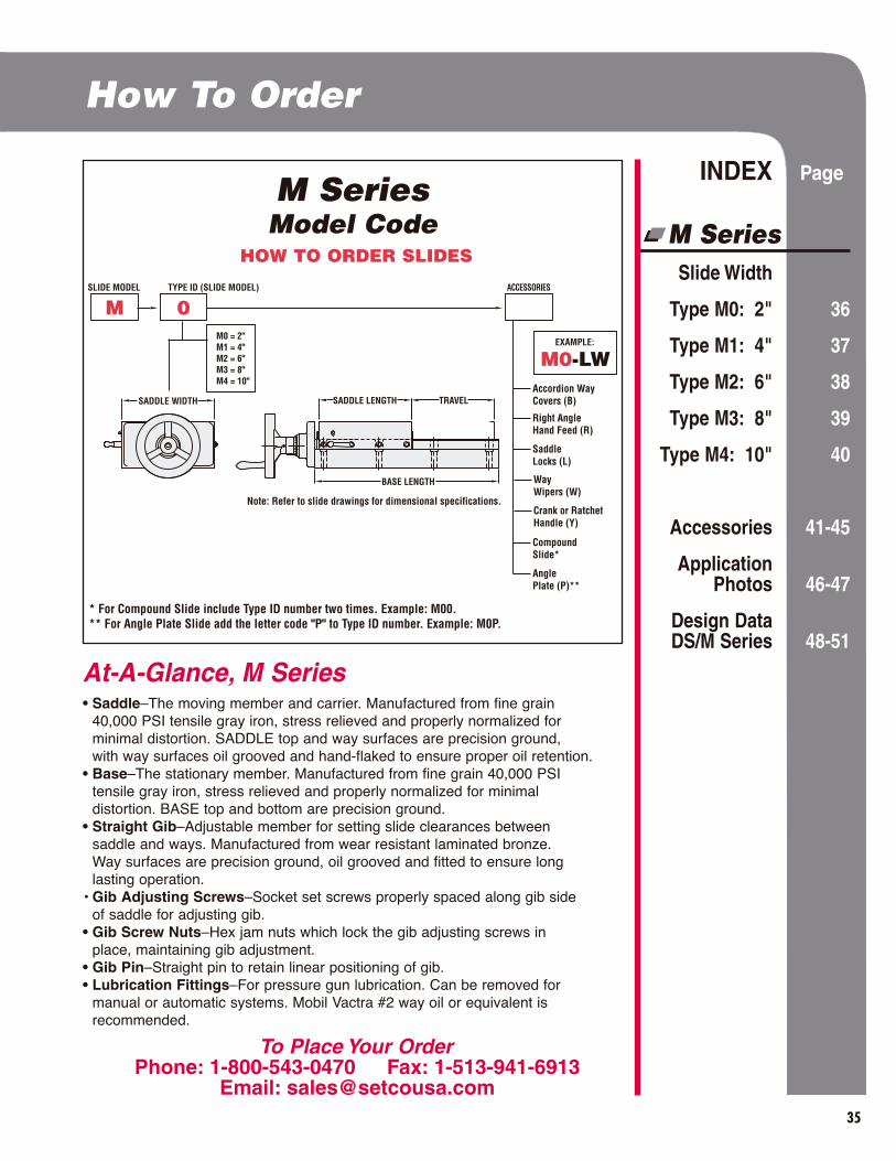
M SeriesModel Code
SLIDE MODEL TYPE ID (SLIDE MODEL) ACCESSORIES
M 0
Accordion Way Covers (B)
Right Angle Hand Feed (R)
Saddle Locks (L)
WayWipers (W)
Crank or Ratchet Handle (Y)
Compound Slide*
AnglePlate (P)**
* For Compound Slide include Type ID number two times. Example: M00.** For Angle Plate Slide add the letter code "P" to Type ID number. Example: M0P.
EXAMPLE:
M0-LWM0 = 2"M1 = 4"M2 = 6"M3 = 8"M4 = 10"
SADDLE WIDTH SADDLE LENGTH TRAVEL
BASE LENGTH
Note: Refer to slide drawings for dimensional specifications.
HOW TO ORDER SLIDES
How To Order

36
M Series: Type M0 2"
• Torque required to turn M0 feedscrew is about 5 in/lb.• When the slide is mounted to a sidewall with its feedscrew at right angles
to the vertical plane, the gib must be on the bottom. (See Slide MountingAttitude, page 48.)
• For load capacities, see Slide Load Capacity chart, page 50.• Slides can be supplied without a micrometer handwheel,
allowing use of a ratchet handle, crank or other device.
• Load capacity is measured atthe saddle; overhanging load decreases capacity.
M0 HAND FEED (Single Axis • Weight: 3.25 lb. • Feedscrew 5/16-40)
M00 COMPOUND HAND FEED (2-Axis • Weight: 6.5 lb.)
M0P VERTICAL ANGLEPLATE WITH HAND FEED (Single Axis • Weight: 7 lb.)
P0 VERTICAL ANGLE PLATE (Weight: 3.75 lb.)
• Vertical Angle Plate can be used to mount other components, workpieces, tools, etc.

37
M Series: Type M1 4"
5/8–10
• Torque required to turn M1 feedscrew is about 15 in/lb.• When the slide is mounted to a sidewall with its feedscrew at right angles to the
vertical plane, the gib must be on the bottom. (See Slide Mounting Attitude, page 48.)• For load capacities, see Slide Load Capacity chart, page 50.• Slides can be supplied without a micrometer handwheel,
allowing use of a ratchet handle, crank or other device.
• Load capacity is measured at the saddle; overhanging load decreasescapacity.
M1 HAND FEED (Single Axis • Weight: 16 lb. • Feedscrew 5/8-10)
M11 COMPOUND HAND FEED (2-Axis • Weight: 32 lb.)
M1P VERTICAL ANGLEPLATE WITH HAND FEED (Single Axis • Weight: 36 lb.)
P1 VERTICAL ANGLE PLATE (Weight: 20 lb.)
• Vertical Angle Plate can be used to mount other components, workpieces, tools, etc.
*A slide stop washer is provided on this vertical slide model.
38
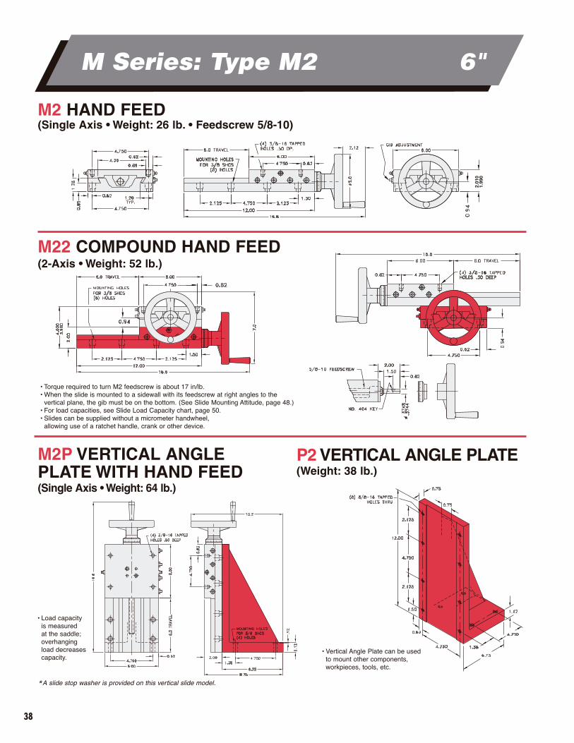
M Series: Type M2 6"
2.01
01.
990
M2 HAND FEED (Single Axis • Weight: 26 lb. • Feedscrew 5/8-10)
M22 COMPOUND HAND FEED (2-Axis • Weight: 52 lb.)
M2P VERTICAL ANGLEPLATE WITH HAND FEED (Single Axis • Weight: 64 lb.)
P2 VERTICAL ANGLE PLATE (Weight: 38 lb.)
• Vertical Angle Plate can be usedto mount other components,workpieces, tools, etc.
• Torque required to turn M2 feedscrew is about 17 in/lb.• When the slide is mounted to a sidewall with its feedscrew at right angles to the
vertical plane, the gib must be on the bottom. (See Slide Mounting Attitude, page 48.)• For load capacities, see Slide Load Capacity chart, page 50.• Slides can be supplied without a micrometer handwheel,
allowing use of a ratchet handle, crank or other device.
*A slide stop washer is provided on this vertical slide model.
• Load capacity is measured at the saddle; overhanging load decreasescapacity.
39
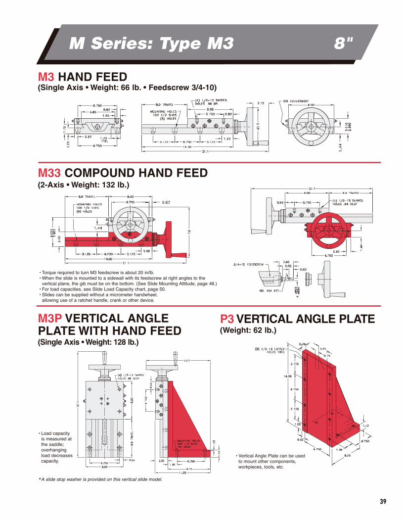
M Series: Type M3 8"
• Torque required to turn M3 feedscrew is about 20 in/lb.• When the slide is mounted to a sidewall with its feedscrew at right angles to the
vertical plane, the gib must be on the bottom. (See Slide Mounting Attitude, page 48.)• For load capacities, see Slide Load Capacity chart, page 50.• Slides can be supplied without a micrometer handwheel,
allowing use of a ratchet handle, crank or other device.
• Load capacityis measured atthe saddle; overhanging load decreasescapacity.
M3 HAND FEED (Single Axis • Weight: 66 lb. • Feedscrew 3/4-10)
M33 COMPOUND HAND FEED (2-Axis • Weight: 132 lb.)
M3P VERTICAL ANGLEPLATE WITH HAND FEED(Single Axis • Weight: 128 lb.)
P3 VERTICAL ANGLE PLATE (Weight: 62 lb.)
• Vertical Angle Plate can be usedto mount other components, workpieces, tools, etc.
*A slide stop washer is provided on this vertical slide model.
40
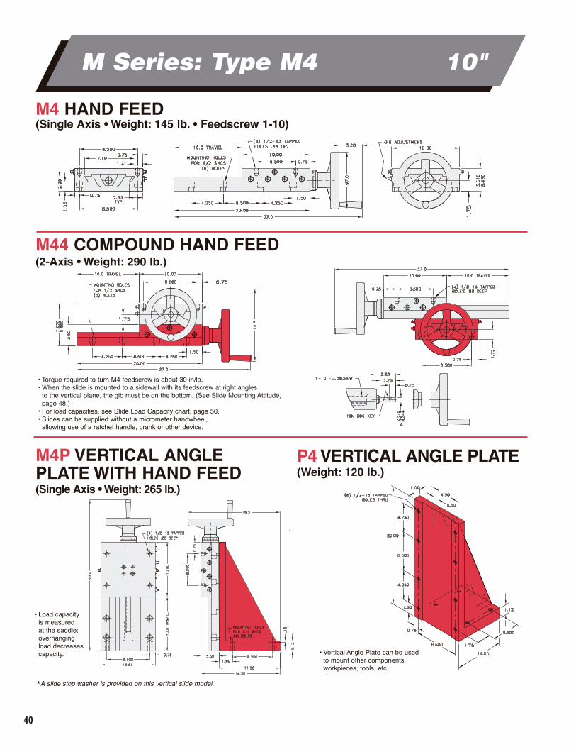
M Series: Type M4 10"
• Torque required to turn M4 feedscrew is about 30 in/lb.• When the slide is mounted to a sidewall with its feedscrew at right angles
to the vertical plane, the gib must be on the bottom. (See Slide Mounting Attitude,page 48.)
• For load capacities, see Slide Load Capacity chart, page 50.• Slides can be supplied without a micrometer handwheel,
allowing use of a ratchet handle, crank or other device.
• Load capacity is measured at the saddle; overhanging load decreasescapacity.
M4 HAND FEED (Single Axis • Weight: 145 lb. • Feedscrew 1-10)
M4P VERTICAL ANGLEPLATE WITH HAND FEED (Single Axis • Weight: 265 lb.)
P4 VERTICAL ANGLE PLATE(Weight: 120 lb.)
• Vertical Angle Plate can be used to mount other components, workpieces, tools, etc.
*A slide stop washer is provided on this vertical slide model.
M44 COMPOUND HAND FEED (2-Axis • Weight: 290 lb.)

41
M Series Accessories
Accordion Way Covers shield slide From harmful contaminants
DIMENSIONS IN INCHESMODEL B CL H OW S T U W
M0
M1-B
M2-B
M3-B
M4-B
N/A
10.00
12.00
16.00
20.00
N/A
0.75
1.03
0.81
1.00
N/A
2.00
2.00
3.00
3.50
N/A
5.06
7.12
10.00
12.12
N/A
6.00
6.00
8.00
10.00
N/A
2.50
3.94
6.38
8.00
N/A
0.53
0.56
1.00
1.06
N/A
4.00
6.00
8.00
10.00
ACCORDION WAY COVERS*(Model Code: B)
Made of hypolon polyester, the optional AccordionWay Covers shield the slide way surfaces, feed mechanisms and slide cavity from abrasive material,coolant and dust. These covers are available for all M Series slides, except Type M0.
When Accordion Way Covers are provided, the slide travel length is reduced due to the bellows stack-up at each end. As the drawing below illustrates, the Accordion Way Covers will extend beyond the sides of the slide (OW dimension) – but not above the top of the saddle.
See chart below for the actual travel available on each M Series slide when equipped with Accordion Way Covers.
Slide Series
Accordion Way Cover
Width ID (6")
SLIDE MODEL CODEM 2 - B
* Consult MASTER/SETCO Solution Team for special covers when contaminants are sharp or heavy in nature.
42
M & DS Series Accessories
STANDARD POSITION
RIGHT
OPTIONALPOSITION
DOWN
OPTIONALPOSITION
LEFT
OPTIONALPOSITION
UP
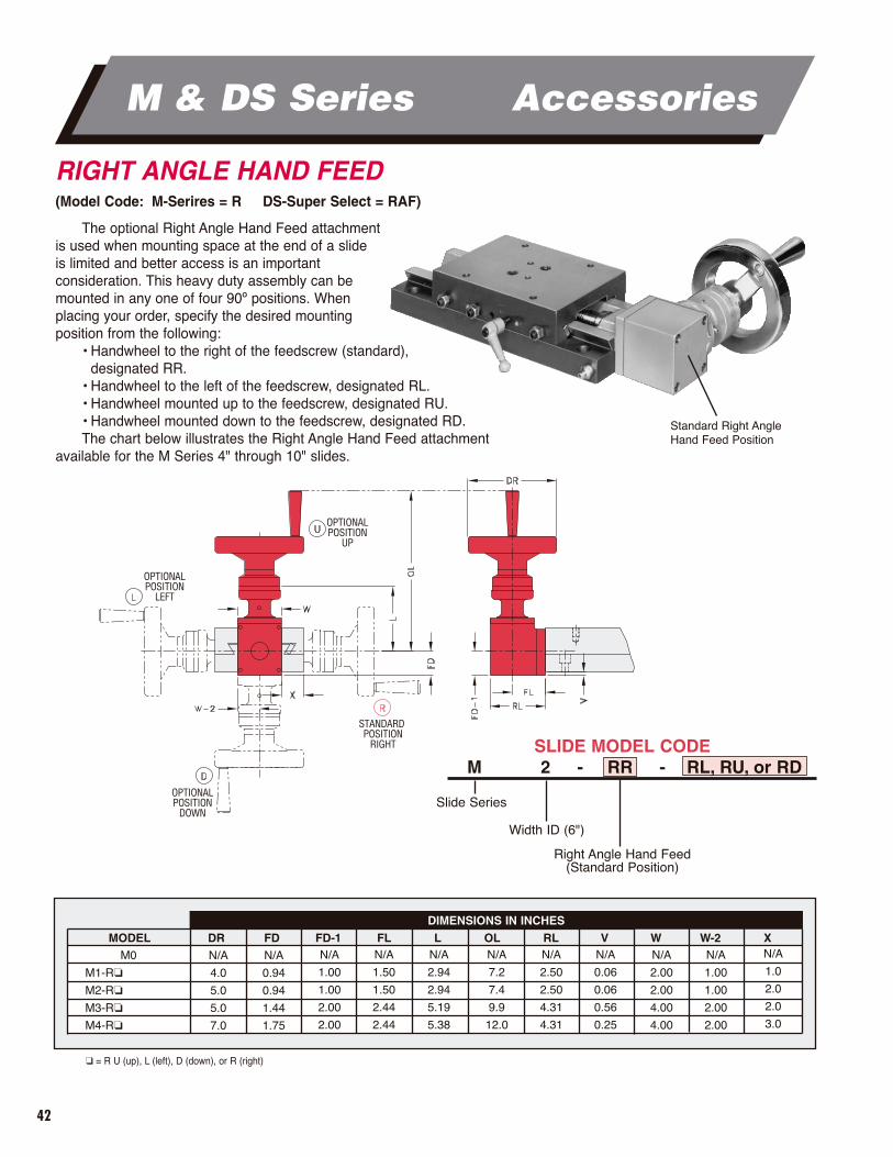
RIGHT ANGLE HAND FEED(Model Code: M-Serires = R DS-Super Select = RAF)
DIMENSIONS IN INCHES
MODEL DR FD FD-1 FL L OL RL V W W-2 XM0
M1-R�
M2-R�
M3-R�
M4-R�
N/A
4.0
5.0
5.0
7.0
N/A
0.94
0.94
1.44
1.75
N/A
1.00
1.00
2.00
2.00
N/A
1.50
1.50
2.44
2.44
N/A
2.94
2.94
5.19
5.38
N/A
7.2
7.4
9.9
12.0
N/A
2.50
2.50
4.31
4.31
N/A
0.06
0.06
0.56
0.25
N/A
2.00
2.00
4.00
4.00
N/A
1.00
1.00
2.00
2.00
N/A
1.0
2.0
2.0
3.0
The optional Right Angle Hand Feed attachment is used when mounting space at the end of a slide is limited and better access is an important consideration. This heavy duty assembly can bemounted in any one of four 90º positions. Whenplacing your order, specify the desired mounting position from the following:
• Handwheel to the right of the feedscrew (standard), designated RR.
• Handwheel to the left of the feedscrew, designated RL.• Handwheel mounted up to the feedscrew, designated RU.• Handwheel mounted down to the feedscrew, designated RD.The chart below illustrates the Right Angle Hand Feed attachment
available for the M Series 4" through 10" slides.
Standard Right Angle Hand Feed Position
Slide Series
Right Angle Hand Feed(Standard Position)
Width ID (6")
SLIDE MODEL CODEM 2 - RR - RL, RU, or RD
� = R U (up), L (left), D (down), or R (right)
43
M Series Accessories
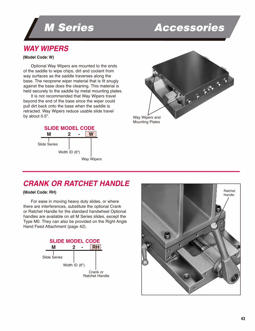
CRANK OR RATCHET HANDLE(Model Code: RH)
For ease in moving heavy duty slides, or wherethere are interferences, substitute the optional Crank or Ratchet Handle for the standard handwheel Optionalhandles are available on all M Series slides, except theType M0. They can also be provided on the Right AngleHand Feed Attachment (page 42).
Ratchet Handle
WAY WIPERS(Model Code: W)
Optional Way Wipers are mounted to the ends of the saddle to wipe chips, dirt and coolant from way surfaces as the saddle traverses along the base. The neoprene wiper material that is fit snuglyagainst the base does the cleaning. This material isheld securely to the saddle by metal mounting plates.
It is not recommended that Way Wipers travelbeyond the end of the base since the wiper could pull dirt back onto the base when the saddle is retracted. Way Wipers reduce usable slide travel by about 0.5". Way Wipers and
Mounting Plates
Slide Series
Way Wipers
Width ID (6")
SLIDE MODEL CODEM 2 - W
Slide Series
Crank orRatchet Handle
Width ID (6")
SLIDE MODEL CODEM 2 - RH
44
M Series Accessories
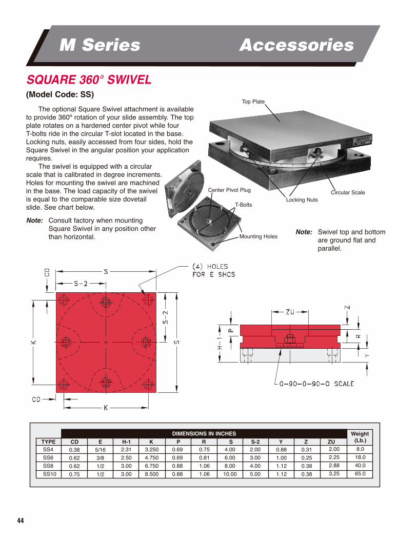
SQUARE 360° SWIVEL(Model Code: SS)
Weight(Lb.)
DIMENSIONS IN INCHES
TYPE CD E H-1 K P R S S-2 Y Z ZUSS4
SS6
SS8
SS10
0.38
0.62
0.62
0.75
5/16
3/8
1/2
1/2
2.31
2.50
3.00
3.00
3.250
4.750
6.750
8.500
0.69
0.69
0.88
0.88
0.75
0.81
1.06
1.06
4.00
6.00
8.00
10.00
2.00
3.00
4.00
5.00
0.88
1.00
1.12
1.12
0.31
0.25
0.38
0.38
2.00
2.25
2.88
3.25
8.0
18.0
40.0
65.0
The optional Square Swivel attachment is availableto provide 360º rotation of your slide assembly. The topplate rotates on a hardened center pivot while four T-bolts ride in the circular T-slot located in the base.Locking nuts, easily accessed from four sides, hold theSquare Swivel in the angular position your applicationrequires.
The swivel is equipped with a circular scale that is calibrated in degree increments. Holes for mounting the swivel are machined in the base. The load capacity of the swivel is equal to the comparable size dovetail slide. See chart below.
Note: Consult factory when mounting Square Swivel in any position other than horizontal.
Top Plate
Circular ScaleLocking Nuts
Center Pivot Plug
T-Bolts
Mounting HolesNote: Swivel top and bottom
are ground flat and parallel.
45
M Series Accessories
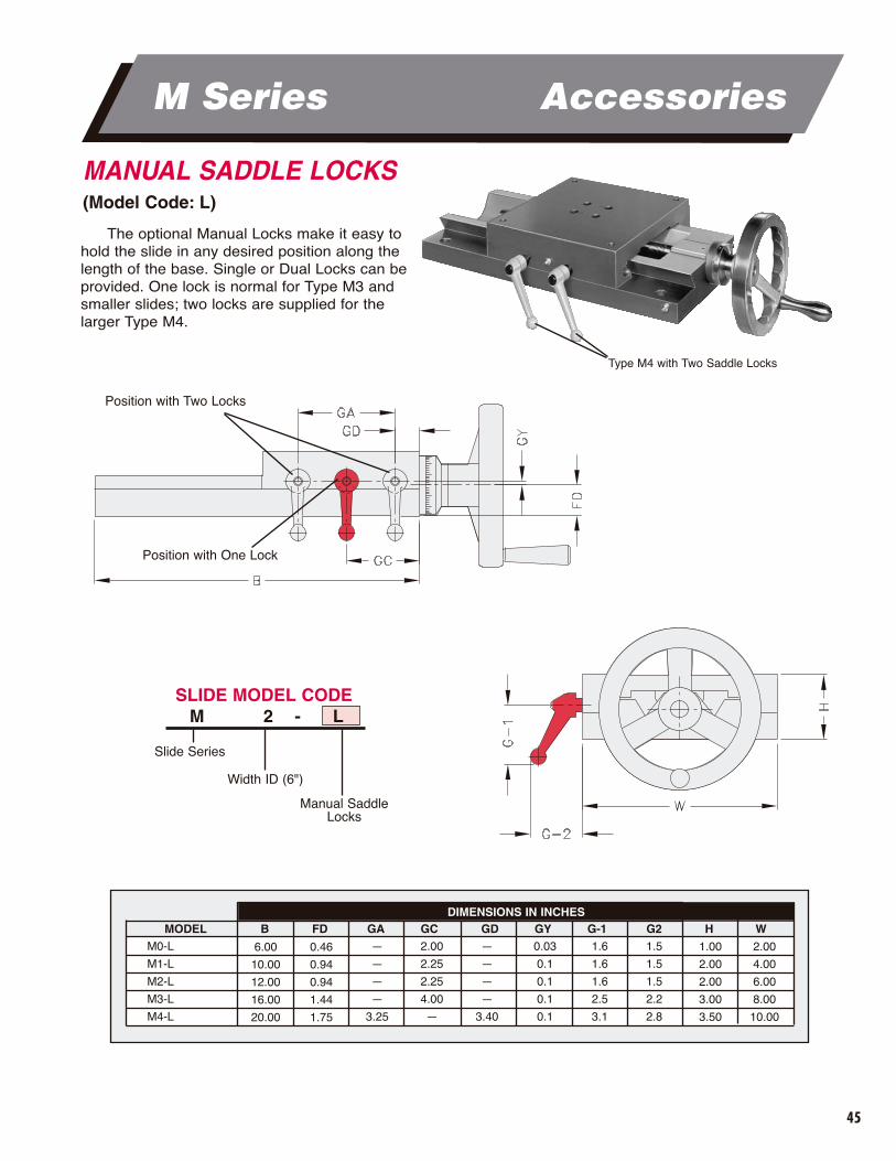
MANUAL SADDLE LOCKS(Model Code: L)
The optional Manual Locks make it easy tohold the slide in any desired position along thelength of the base. Single or Dual Locks can beprovided. One lock is normal for Type M3 andsmaller slides; two locks are supplied for thelarger Type M4.
DIMENSIONS IN INCHESMODEL B FD GA GC GD GY G-1 G2 H W
M0-L
M1-L
M2-L
M3-L
M4-L
6.00
10.00
12.00
16.00
20.00
0.46
0.94
0.94
1.44
1.75
—
—
—
—
3.25
2.00
2.25
2.25
4.00
—
—
—
—
—
3.40
0.03
0.1
0.1
0.1
0.1
1.6
1.6
1.6
2.5
3.1
1.5
1.5
1.5
2.2
2.8
1.00
2.00
2.00
3.00
3.50
2.00
4.00
6.00
8.00
10.00
Type M4 with Two Saddle Locks
Position with Two Locks
Position with One Lock
Slide Series
Manual SaddleLocks
Width ID (6")
SLIDE MODEL CODEM 2 - L

46
M Series Application Photos
M3P Angle Plate Slide with Hand Feed andAccordion Way Covers. M33 Compound Slide
with Hand Feed andAccordion WayCovers.
M0 Single Feed withMicrometer Dial.
INTRODUCTIONSETCO’s motion experts can provide assistance
with linear and rotary movement applications.Once we know your manufacturing demands,
we can recommend the slide or spindle combinationthat meets all of your needs. This one-stop solutioneliminates your concerns with source responsibility.
Shown here are a variety of solutions for a variety of industries, including aerospace, defense, automotive, agriculture, off-road and trucking.
Type 6101-36G/M2L StandardSize 5 Grinding Spindle with feet milled to flush mount on an M2L (6" wide) Dovetail Slide with saddle lock.
M11 Compound Slide with Hand Feed.
Photo #3866MPhoto #3870M
Photo #3995M
Photo #3862M
Photo #3913M
47
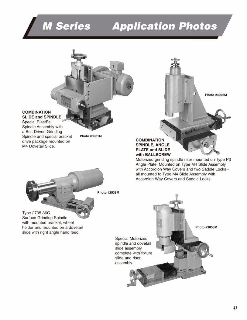
COMBINATION SLIDE and SPINDLE Special Rise/Fall Spindle Assembly with a Belt Driven Grinding Spindle and special bracketdrive package mounted onM4 Dovetail Slide.
COMBINATIONSPINDLE, ANGLEPLATE and SLIDE with BALLSCREWMotorized grinding spindle riser mounted on Type P3Angle Plate. Mounted on Type M4 Slide Assemblywith Accordion Way Covers and two Saddle Locks - all mounted to Type M4 Slide Assembly withAccordion Way Covers and Saddle Locks.
M Series Application Photos
Type 2705-36GSurface Grinding Spindlewith mounted bracket, wheelholder and mounted on a dovetailslide with right angle hand feed.
Special Motorized spindle and dovetail slide assembly complete with fixtureslide and riserassembly.
Photo #3931M
Photo #2539M
Photo #3853M
Photo #4076M
48
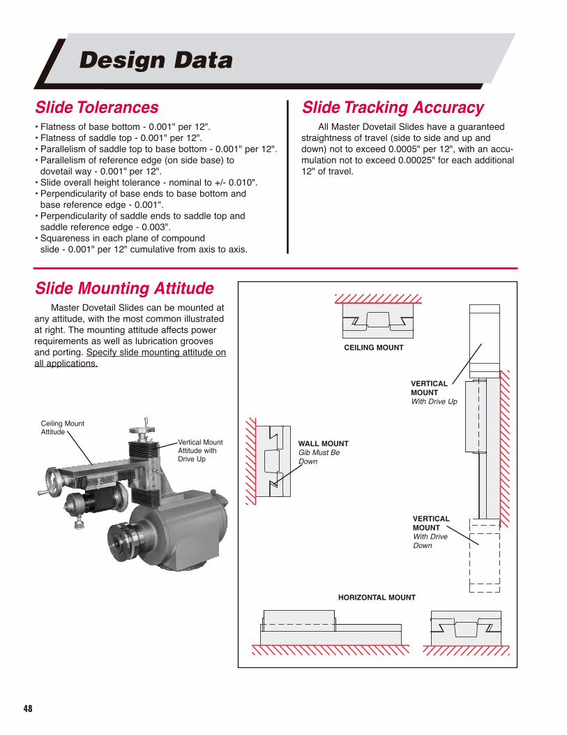
Slide Tolerances• Flatness of base bottom - 0.001" per 12".• Flatness of saddle top - 0.001" per 12".• Parallelism of saddle top to base bottom - 0.001" per 12".• Parallelism of reference edge (on side base) to
dovetail way - 0.001" per 12".• Slide overall height tolerance - nominal to +/- 0.010".• Perpendicularity of base ends to base bottom and
base reference edge - 0.001".• Perpendicularity of saddle ends to saddle top and
saddle reference edge - 0.003".• Squareness in each plane of compound
slide - 0.001" per 12" cumulative from axis to axis.
Design Data
Slide Mounting AttitudeMaster Dovetail Slides can be mounted at
any attitude, with the most common illustratedat right. The mounting attitude affects powerrequirements as well as lubrication groovesand porting. Specify slide mounting attitude onall applications.
Slide Tracking AccuracyAll Master Dovetail Slides have a guaranteed
straightness of travel (side to side and up anddown) not to exceed 0.0005" per 12", with an accu-mulation not to exceed 0.00025" for each additional12" of travel.
WALL MOUNTGib Must BeDown
CEILING MOUNT
VERTICALMOUNTWith Drive Up
VERTICALMOUNTWith DriveDown
HORIZONTAL MOUNT
Ceiling Mount Attitude
Vertical MountAttitude withDrive Up
49
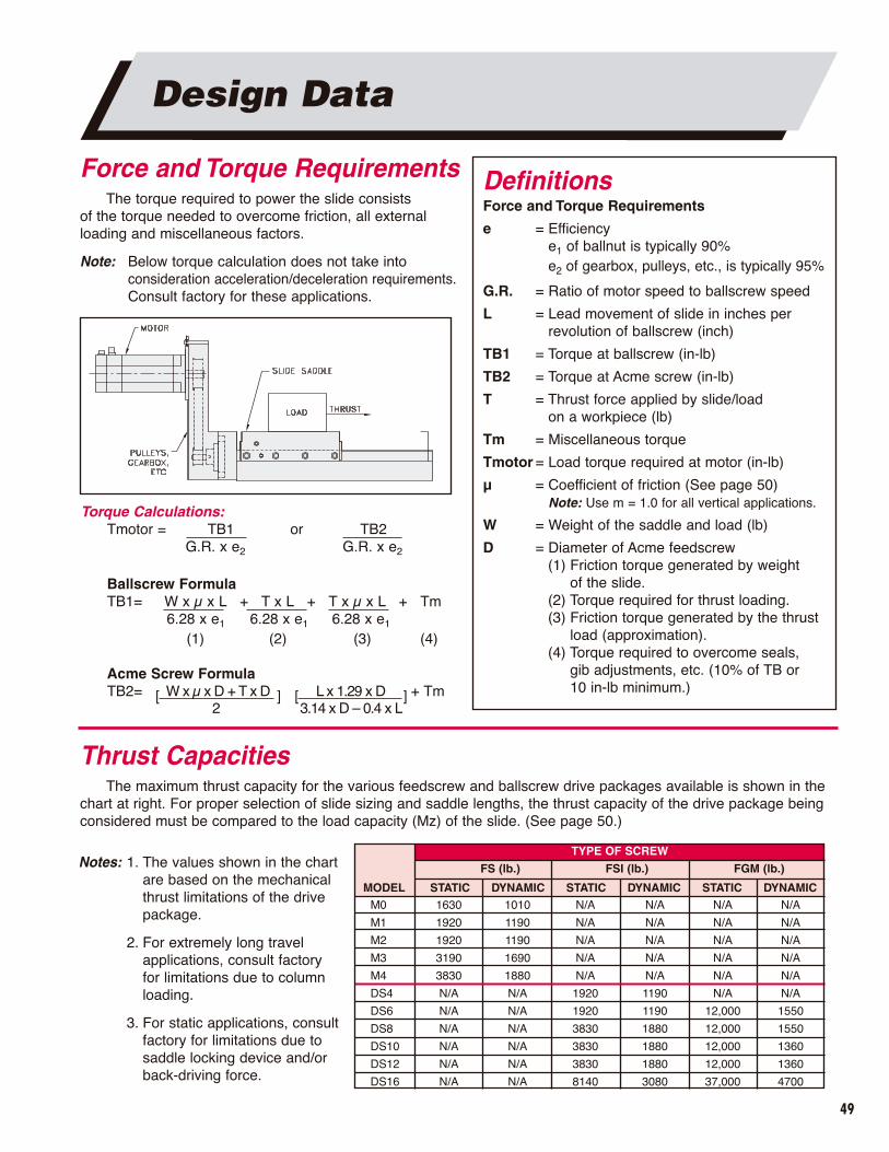
Force and Torque RequirementsThe torque required to power the slide consists
of the torque needed to overcome friction, all external loading and miscellaneous factors.
Note: Below torque calculation does not take into consideration acceleration/deceleration requirements.Consult factory for these applications.
Torque Calculations:Tmotor = TB1 or TB2
G.R. x e2 G.R. x e2
Ballscrew FormulaTB1= W x µ x L + T x L + T x µ x L + Tm
6.28 x e1 6.28 x e1 6.28 x e1
(1) (2) (3) (4)
Acme Screw FormulaTB2= [ W x µ x D + T x D ] [ L x 1.29 x D ] + Tm
2 3.14 x D – 0.4 x L
Thrust CapacitiesThe maximum thrust capacity for the various feedscrew and ballscrew drive packages available is shown in the
chart at right. For proper selection of slide sizing and saddle lengths, the thrust capacity of the drive package beingconsidered must be compared to the load capacity (Mz) of the slide. (See page 50.)
DefinitionsForce and Torque Requirements
e = Efficiencye1 of ballnut is typically 90%e2 of gearbox, pulleys, etc., is typically 95%
G.R. = Ratio of motor speed to ballscrew speed
L = Lead movement of slide in inches per revolution of ballscrew (inch)
TB1 = Torque at ballscrew (in-lb)
TB2 = Torque at Acme screw (in-lb)
T = Thrust force applied by slide/load on a workpiece (lb)
Tm = Miscellaneous torque
Tmotor = Load torque required at motor (in-lb)
µ = Coefficient of friction (See page 50)Note: Use m = 1.0 for all vertical applications.
W = Weight of the saddle and load (lb)
D = Diameter of Acme feedscrew(1) Friction torque generated by weight
of the slide.(2) Torque required for thrust loading.(3) Friction torque generated by the thrust
load (approximation).(4) Torque required to overcome seals,
gib adjustments, etc. (10% of TB or 10 in-lb minimum.)
Design Data
TYPE OF SCREW
FS (lb.) FSI (lb.) FGM (lb.)
MODEL STATIC DYNAMIC STATIC DYNAMIC STATIC DYNAMICM0
M1
M2
M3
M4
DS4
DS6
DS8
DS10
DS12
DS16
1630
1920
1920
3190
3830
N/A
N/A
N/A
N/A
N/A
N/A
1010
1190
1190
1690
1880
N/A
N/A
N/A
N/A
N/A
N/A
N/A
N/A
N/A
N/A
N/A
1920
1920
3830
3830
3830
8140
N/A
N/A
N/A
N/A
N/A
1190
1190
1880
1880
1880
3080
Notes: 1. The values shown in the chartare based on the mechanicalthrust limitations of the drivepackage.
2. For extremely long travel applications, consult factory for limitations due to columnloading.
3. For static applications, consultfactory for limitations due tosaddle locking device and/orback-driving force.
N/A
N/A
N/A
N/A
N/A
N/A
12,000
12,000
12,000
12,000
37,000
N/A
N/A
N/A
N/A
N/A
N/A
1550
1550
1360
1360
4700
50
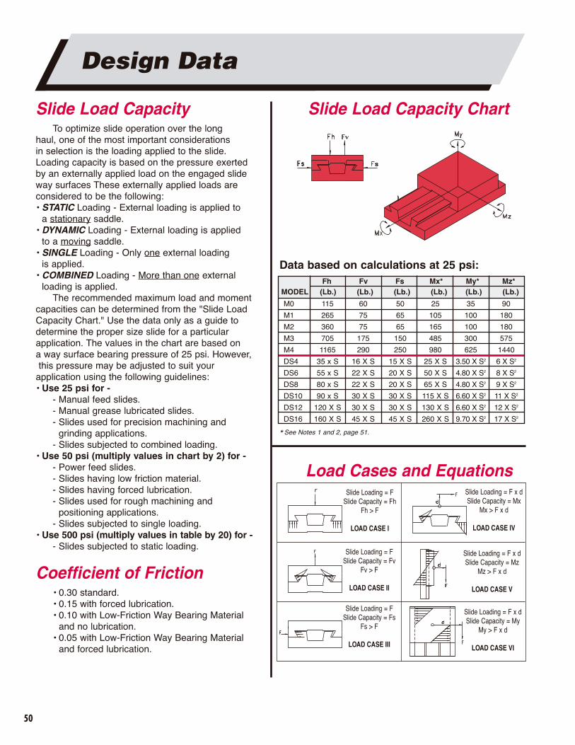
Slide Load CapacityTo optimize slide operation over the long
haul, one of the most important considerations in selection is the loading applied to the slide. Loading capacity is based on the pressure exerted by an externally applied load on the engaged slide way surfaces These externally applied loads are considered to be the following:• STATIC Loading - External loading is applied to
a stationary saddle.• DYNAMIC Loading - External loading is applied
to a moving saddle.• SINGLE Loading - Only one external loading
is applied. • COMBINED Loading - More than one external
loading is applied.The recommended maximum load and moment
capacities can be determined from the "Slide LoadCapacity Chart." Use the data only as a guide to determine the proper size slide for a particular application. The values in the chart are based on a way surface bearing pressure of 25 psi. However,this pressure may be adjusted to suit your
application using the following guidelines:• Use 25 psi for -
- Manual feed slides.- Manual grease lubricated slides.- Slides used for precision machining and
grinding applications.- Slides subjected to combined loading.
• Use 50 psi (multiply values in chart by 2) for -- Power feed slides.- Slides having low friction material.- Slides having forced lubrication.- Slides used for rough machining and
positioning applications.- Slides subjected to single loading.
• Use 500 psi (multiply values in table by 20) for -- Slides subjected to static loading.
Coefficient of Friction• 0.30 standard.• 0.15 with forced lubrication.• 0.10 with Low-Friction Way Bearing Material
and no lubrication.• 0.05 with Low-Friction Way Bearing Material
and forced lubrication.
Load Cases and Equations
Slide Load Capacity Chart
Slide Loading = FSlide Capacity = Fh
Fh > F
LOAD CASE I
Slide Loading = FSlide Capacity = Fv
Fv > F
LOAD CASE II
Slide Loading = FSlide Capacity = Fs
Fs > F
LOAD CASE III
Slide Loading = F x dSlide Capacity = Mx
Mx > F x d
LOAD CASE IV
Slide Loading = F x dSlide Capacity = Mz
Mz > F x d
LOAD CASE V
Slide Loading = F x dSlide Capacity = My
My > F x d
LOAD CASE VI
Design Data
MODEL (Lb.) (Lb.) (Lb.) (Lb.) (Lb.) (Lb.)Fh Fv Fs Mx* My* Mz*
M0
M1
M2
M3
M4
DS4
DS6
DS8
DS10
DS12
DS16
115
265
360
705
1165
35 x S
55 x S
80 x S
90 x S
120 X S
160 X S
60
75
75
175
290
16 X S
22 X S
22 X S
30 X S
30 X S
45 X S
50
65
65
150
250
15 X S
20 X S
20 X S
30 X S
30 X S
45 X S
25
105
165
485
980
25 X S
50 X S
65 X S
115 X S
130 X S
260 X S
35
100
100
300
625
3.50 X S2
4.80 X S2
4.80 X S2
6.60 X S2
6.60 X S2
9.70 X S2
90
180
180
575
1440
6 X S2
8 X S2
9 X S2
11 X S2
12 X S2
17 X S2
* See Notes 1 and 2, page 51.
Data based on calculations at 25 psi:

51
Design Data
DefinitionsSlide Load Capacityd = Perpendicular distance (inches) from
saddle to applied load
Fh = Applied load (lb.) perpendicular and into plane of saddle top
Fv = Applied load (lb.) perpendicular and away from plane of saddle top
F = Applied external load (lb.)
Fs = Applied load perpendicular and into or away from plane of saddle side (lb)
Mx = Moment about the saddle width (in-lb.)
My = Moment about plane of saddle top (in-lb.)
Mz = Moment about saddle length (in-lb.)
DYNAMIC Loading - moving weight of spindleLoad Case = 1Combined Loading = 25 psiLoading F = 600 lbEquation: Fh > F
Fh > 600 lbConsidering a DS12 Dovetail SlideLoad Capacity (25 psi), Fh = 120 x S
120 x S = 600S = 5"
DYNAMIC Loading - feeding boring spindleLoad Case = VCombined Loading = 25 psiLoading = F x d
= 500 (4)= 2000 in-lb
Equation: Mz > F x dMz > 2000 in-lb
Load Capacity (25 psi), Mz = 12 x S2
12 x S2 = 2000S = 13"
Use a DS12 Slide with 13" long saddle.
Combined Load CaseHere’s an example illustrating combined loading—
a slide subjected to two dynamic loads. A 600 lb. boring spindle is mounted to a horizontal slide and will be subjected to a 500 lb. thrust load. Two calculationsmust be performed: one to determine the necessary saddle length based on the weight of the spindle; a second based on the thrust load. Whichever calculation yields the greater saddle length, this is the number that must be used.
In cases where both calculations suggest a saddlelength less than the width of the slide, then either a smaller width slide can be used or the saddle length must be increased to a minimum length (i.e., the saddlelength cannot be shorter than the width of the slide).
Notes: 1. For applications where load is applied in the direction of slide travel, the slide loadcapacity may be limited to the capacity of the slide feed mechanism. Check the load values with the maximum thrust capacities for the feed mechanism being used.
For static applications, the slide load capaci-ty may be limited by the saddle lockingdevice.
Slide load capacity is based on uniformlyapplied loads and moments. Consult factoryon all applications where shock loading ispresent.
2. For applications involving an Mx moment, the slide load capacity may be limited by the Fs Load capacity.
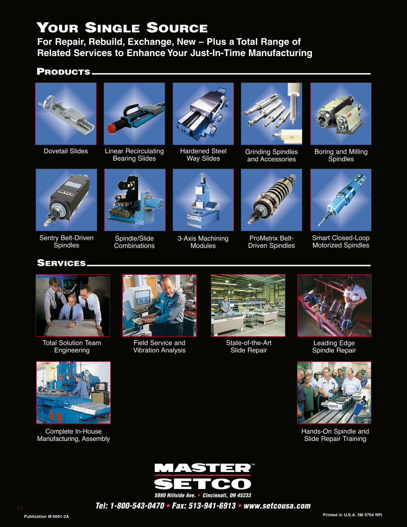
Dovetail Slides Linear RecirculatingBearing Slides
Spindle/SlideCombinations
Hardened Steel Way Slides
Sentry Belt-DrivenSpindles
ProMetrix Belt-Driven Spindles
Grinding Spindlesand Accessories
Boring and MillingSpindles
Total Solution TeamEngineering
Field Service andVibration Analysis
State-of-the-Art Slide Repair
Leading Edge Spindle Repair
Complete In-HouseManufacturing, Assembly
Hands-On Spindle andSlide Repair Training
Smart Closed-LoopMotorized Spindles
3-Axis MachiningModules
For Repair, Rebuild, Exchange, New – Plus a Total Range ofRelated Services to Enhance Your Just-In-Time Manufacturing
SERVICES
PRODUCTS
YOUR SINGLE SOURCE
Publication M-0001-2A Printed in U.S.A. 5M 0704 RPI
5880 Hillside Ave. • Cincinnati, OH 45233
Tel: 1-800-543-0470 • Fax: 513-941-6913 • www.setcousa.com00