Embed Size (px)
Citation preview
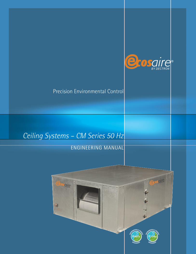
Ecosaire® CEILING MOUNT Engineering Manual
Ceiling Systems – CM Series 50 Hz
Precision Environmental Control
ENGINEERING MANUAL
R407c R134a

1
NOMENCLATURE . . . . . . . . . . . . . . . . . . . . . . . . . . . . . . . . . . . . . . . . . . . . . . . . . . . . . . . . . . . . . . . . . . . . . . . . 2
Total Protection . . . . . . . . . . . . . . . . . . . . . . . . . . . . . . . . . . . . . . . . . . . . . . . . . . . . . . . . . . . . . . . . . . . . . . . . .3
Standard Features and Options . . . . . . . . . . . . . . . . . . . . . . . . . . . . . . . . . . . . . . . . . . . . . . . . . . . . . . . . . . . . .4
Technical Data . . . . . . . . . . . . . . . . . . . . . . . . . . . . . . . . . . . . . . . . . . . . . . . . . . . . . . . . . . . . . . . . . . . . . . . . . . .7
Dimensional Drawings . . . . . . . . . . . . . . . . . . . . . . . . . . . . . . . . . . . . . . . . . . . . . . . . . . . . . . . . . . . . . . . . . . .21
Engineering Guide Specifications . . . . . . . . . . . . . . . . . . . . . . . . . . . . . . . . . . . . . . . . . . . . . . . . . . . . . . . . . .24
Ecosaire® CEILING MOUNT Engineering Manual
2
Ecosaire® CEILING MOUNT Engineering Manual
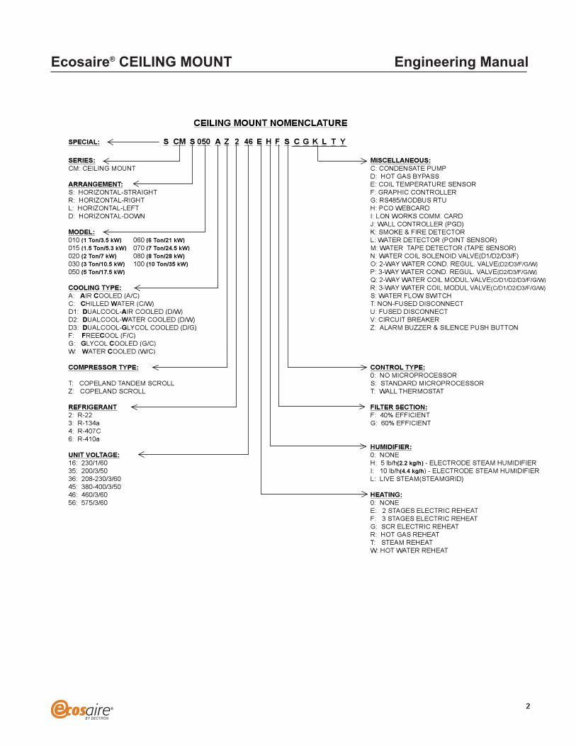
SPECIAL: S CM S 050 A Z 2 46 E H F S C G K L T Y
SERIES: MISCELLANEOUS:
CM: CEILING MOUNT C: CONDENSATE PUMP
D: HOT GAS BYPASS
ARRANGEMENT: E: COIL TEMPERATURE SENSOR
S: HORIZONTAL-STRAIGHT F: GRAPHIC CONTROLLER
R: HORIZONTAL-RIGHT G: RS485/MODBUS RTU
L: HORIZONTAL-LEFT H: PCO WEBCARD
D: HORIZONTAL-DOWN I: LON WORKS COMM. CARD
J: WALL CONTROLLER (PGD)
MODEL: K: SMOKE & FIRE DETECTOR
010 (1 Ton/3.5 kW) 060 (6 Ton/21 kW) L: WATER DETECTOR (POINT SENSOR)
015 (1.5 Ton/5.3 kW) 070 (7 Ton/24.5 kW) M: WATER TAPE DETECTOR (TAPE SENSOR)
020 (2 Ton/7 kW) 080 (8 Ton/28 kW) N: WATER COIL SOLENOID VALVE(D1/D2/D3/F)
030 (3 Ton/10.5 kW) 100 (10 Ton/35 kW) O: 2-WAY WATER COND. REGUL. VALVE(D2/D3/F/G/W)
050 (5 Ton/17.5 kW) P: 3-WAY WATER COND. REGUL. VALVE(D2/D3/F/G/W)
Q: 2-WAY WATER COIL MODUL.VALVE(C/D1/D2/D3/F/G/W)
COOLING TYPE: R: 3-WAY WATER COIL MODUL.VALVE(C/D1/D2/D3/F/G/W)
A: AIR COOLED (A/C) S: WATER FLOW SWITCH
C: CHILLED WATER (C/W) T: NON-FUSED DISCONNECT
D1: DUALCOOL-AIR COOLED (D/W) U: FUSED DISCONNECT
D2: DUALCOOL-WATER COOLED (D/W) V: CIRCUIT BREAKER
D3: DUALCOOL-GLYCOL COOLED (D/G) Z: ALARM BUZZER & SILENCE PUSH BUTTON
F: FREECOOL (F/C)
G: GLYCOL COOLED (G/C)
W: WATER COOLED (W/C)
COMPRESSOR TYPE: CONTROL TYPE:
0: NO MICROPROCESSOR
T: COPELAND TANDEM SCROLL S: STANDARD MICROPROCESSOR
Z: COPELAND SCROLL T: WALL THERMOSTAT
REFRIGERANT FILTER SECTION:
2: R-22 F: 40% EFFICIENT
3: R-134a G: 60% EFFICIENT
4: R-407C
6: R-410a
HUMIDIFIER:
UNIT VOLTAGE: 0: NONE
16: 230/1/60 H: 5 lb/h(2.2 kg/h) - ELECTRODE STEAM HUMIDIFIER
35: 200/3/50 I: 10 lb/h(4.4 kg/h) - ELECTRODE STEAM HUMIDIFIER
36: 208-230/3/60 L: LIVE STEAM(STEAMGRID)
45: 380-400/3/50
46: 460/3/60 HEATING:
56: 575/3/60 0: NONE
E: 2 STAGES ELECTRIC REHEAT
F: 3 STAGES ELECTRIC REHEAT
G: SCR ELECTRIC REHEAT
R: HOT GAS REHEAT
T: STEAM REHEAT
W: HOT WATER REHEAT
CEILING MOUNT NOMENCLATURE

Reliability
Efficiency
Serviceability
Ecosaire® Features
TOTAL PROTECTION — THE ECOSAIRE® APPROACH
Ecosaire® has been maintaining optimum operating conditions in data centers throughout the world for more than three decades.
Recognizing the emerging trends toward smaller, more powerful hardware with reducedcooling requirements, Ecosaire® designed the CM Series of three, five and seven-ton cooling unitswith features specifically aimed at providing increased reliability, serviceability, and energyefficiency.
Heavy-duty Scroll compressors, all-copper refrigeration tubing, state-of-the-art microprocessorcontrols, heavy-duty electrical components, and the Humitronic canister humidifier all contribute toexceptional durability. Separate circuit breakers protect the compressor, fan, humidifier, and electricreheat so there are no troublesome fuses to replace. The CM Series units provide year-round service,twenty-four hours a day, 365-days a year.
Computer rooms are kept at comparatively high humidity conditions to prevent staticelectricity problems. Most air conditioners remove this humidity as a normal function of the cooling process, forcing their humidifier to make up the loss. Since an electric humidifier can bevery expensive to operate, Ecosaire® has designed the CM Series so it does not remove excessivehumidity during normal operation. By providing high sensible cooling, compressor energy is notwasted on unnecessary dehumidification so the humidifier does not have to work overtime.
By providing high sensible cooling, compressor energy is not wasted on unnecessarydehumidification so the humidifier does not have to work overtime.
Few business situations require more immediate attention than a data center that has beenshut down. Should a problem arise with the CM Series, it can be serviced with exceptional ease.Readily accessible compressors, fan assemblies, and electrical components assure quick repair. Each belt-driven fan assembly employs a blower motor set for fast changeouts. Total side serviceprovides easy access to the air filters and components.
ALL UNITS FEATURE:
• High sensible cooling• Small footprint• Microprocessor controls• Non-locking disconnect switch• Individual branch circuit breakers• Thermal/acoustical insulation on all interior cabinet surfaces • Two pleated filters• Crankcase heater• Refrigerant reclaim valve• Automatic restart after power failure• Horizontal discharge• Quick changeout blower assemblies• Belt-driven blowers• ETL Listed
3
Ecosaire® CEILING MOUNT Engineering Manual

Supervisaire® Controls
Belt-Driven Blower Motors
Efficient RefrigerationSystem
Convenient ComponentAccess
Disconnect Switch
One-Year Parts Warranty
Remote Air-CooledCondenser (air-cooled only)
Water-Cooled Condenser(water and glycol units)
Remote Glycol Cooler(water and glycol units)
STANDARD FEATURES
The Supervisaire® Microprocessor Controls provide extremely user-friendly, programmablemonitoring and control for all Ecosaire® Precision Environment Control systems. Individual Ecosaire®units can be connected to a built-in local area network together with a supervisory panel completewith a backlit graphics display for robust redundant environmental control. At the same time, thesystem can be connected to a personal computer supervisory system either directly or via a network,or to a BACNET™, ECHELON™ and MODBUS™ interface.
A wall-mounted remote control panel with display is standard, and can be mounted in a convenientlocation.
Efficient motors power each belt-driven blower. Each blower assembly is accessible through the side of the unit and allows the blower to be removed and replaced quickly should the need arise. Each blower motor is two-speed to allow even air flow over the entire coil while the unit isdehumidifying with reduced air flow. On down flow units, a vertical air discharge plenum helpsreduce back pressure for maximum air flow and efficiency.
The refrigeration system consists of a high-efficiency Scroll compressor, filter/dryer, low-pressure switch, manual-reset high-pressure switch, externally-equalized thermal-expansion valve,sight glass/moisture indicator, refrigerant reclaim valve and refrigeration service valves.
The compressor is located behind an access panel for ease of service while in operation. Coppercooling coils and refrigeration tubing are used throughout. The cooling coil includes a corrosion-resistant stainless steel drain pan.
Ecosaire® has given careful consideration to all the needs of the serviceman. We made sure thateach component could be serviced or replaced without interference from other parts or from theunit itself. All refrigeration and humidifier components are easily accessible. Electrical componentsare conveniently located at the front of the unit and are positioned for easy changeout. The filterscan be replaced from the side. Easy side service access also means zero clearance requirements onboth ends of the unit, allowing installation in tight places.
A factory mounted non-locking disconnect switch is standard on all CM Series units,eliminating the need for a field supplied, wall-mounted disconnect.
All CM Series equipment are warranted to be free from defects in material and workmanshipfor a period of one year.
STANDARD FEATURES/INDIVIDUAL SYSTEMS
The standard air-cooled condenser provides rated cooling capacity at an outdoor ambient of35°C (95°F). Variable speed fan controls provide operation down to –26.9°C (–20°F). Head pressurecontrols system (flooded condenser) with receivers provide operation down to –40°C (–40°F).
The counterflow water-cooled condenser is a heavy-duty brazed-plate heat exchangerconstructed of AISI-316 stainless steel. It is fitted with a two-way, head pressure controlled,10.3 BAR (150 psig), water-regulating valve. (See field-installed accessories).
The standard glycol cooler provides rated cooling capacity at an outdoor ambient of 35°C(95°F). Factory-mounted fan-cycling controls regulate the glycol temperature. (See field-installedaccessories).
4
Ecosaire® CEILING MOUNT Engineering Manual
Humitronic® Humidifier
Electric Reheat Coil
Hot-Gas Reheat
Hot-Water Reheat
Full-FunctionMicroprocessor Control
Low-AmbientAir-Cooled Condenser
Firestat/Smoke Detector
Water Detector
High-PressureWater-Regulating Valve
Three-WayWater-Regulating Valve
Hot Gas Bypass Valve
High-Efficiency Air Filter (60%)
Extended CompressorWarranty
FACTORY-INSTALLED OPTIONS
The Humitronic® steam canister provides 100 percent particle-free steam to the computer roomwhich is essential to computer reliability. Steam canisters operate with greater efficiency and lessmaintenance than any infrared or immersion humidifier available. The humidifier can be adjusteddown to 20 percent of rated capacity to match room load conditions.
Steam is generated by passing an electric current through ordinary tap water in a non-conductivecylinder. The water quickly reaches boiling temperature, producing pure steam. No other form ofhumidification is as clean.
Installation is simple. No expensive water treatment is required. A simple 6.35 mm (1/4”) copperor cold-water supply tube is all that is needed.
Service requirements are reduced to a minimum. When the plastic cylinder is filled withcontaminants, the cylinder is simply discarded and quickly replaced.
Enclosed, low-watt density, fin-tube electric heating elements are available to maintain roomtemperature requirements. They are designed to withstand moist conditions and feature optional 2, 3 stage or proportional control.
A hot-gas reheat coil can be furnished complete with three-way hot-gas valve and arefrigerant check valve. The coil is constructed of copper tubes expanded into aluminum fins. The hot-gas reheat coil maintains room temperature during the dehumidification cycle only.
A hot-water coil can be furnished to maintain room temperature. The coil is complete withtwo-way valve and Y-strainer. The coil is constructed of copper tubes expanded into aluminum fins.
Supervisaire® Microprocessor Controls provide easy-to-use, programmable monitoring andcontrol for each unit. Precision control is enhanced by presenting the user with current roomconditions, set-point control, system operational status, password protection, screen scrolling,menu-driven displays, alarm history and more.
For colder climates, the air-cooled condenser can be provided with a factory-installed three-way head-pressure control valve, a check valve, and an insulated, heated liquid receiver sized to provide –40°C (–40°F) low-ambient operation.
A factory-mounted combination fire and smoke detector is available to activate the unit’salarm and to shut down the unit.
The CM Series can be provided with a factory-installed water detector. The standard arrange-ment includes two water sensors pre-wired to a ten-foot cable. Up to four sensors can be ordered.
The unit can be supplied with a two-way high-pressure water-regulating valve rated at 20.7 BAR(300 psig).
The unit can be supplied with a three-way water-regulating valve rated at 20.7 BAR (300 psig).
The unit can be supplied with a hot gas bypass valve to allow optimum unit operation atreduced heat load capacity condition.
The unit can be supplied with a high efficiency air filter to allow filtration at higher level. The disposable filter shall be rated not less than 60% efficient by ASHRAE 52-76 method.
An extended compressor warranty is available. It provides for a replacement compressor for a period as specified.
5
Ecosaire® CEILING MOUNT Engineering Manual
High-AmbientAir-Cooled Condenser
High-AmbientGlycol Cooler
Single/DualPump Packages
Condensate Pump
FIELD-INSTALLED ACCESSORIES
Air-cooled condensers are available to provide rated cooling capacity at an outdoortemperature of 38, 40 or 43°C (100, 105 or 110°F). They feature factory-mounted controls, coppertubing and variable speed fan controls to allow operation down to –26.9°C (–20°F). Head pressurecontrols system (flooded condenser) with receivers provide operation down to –40°C (–40°F).
Glycol coolers are available to provide rated cooling capacity at outdoor temperatures of 38, 40 or 43°C (100, 105 or 110°F). They feature factory-mounted controls, copper tubing and fancycling to control glycol temperature.
A field mounted pump and pump control panel is available for glycol installations. Glycolsystems requiring optimum system protection can be supplied with dual full-sized pumps. When the flow switch senses a loss of flow, the controls will automatically start the stand-by pump andactivate a visual and audible alarm on the dual-pump control panel. The control panel includes analarm silence switch, pump-run-indicator lights, and lead/lag switch. With the pump package, anaccessory kit is provided containing an expansion tank, air purger, air vent and two check valves.
The optional condensate pump quickly pumps condensate or humidifier spillage water to a remote drain. It is rated for 76 l/h at 5.7 m (20 gph at 18 ft) head and is complete with motor,reservoir and float switch.
6
Ecosaire® CEILING MOUNT Engineering Manual

7
Ecosaire® CEILING MOUNT Engineering Manual
MODEL26.7°C (80 °F) DB / 19.5°C (67 °F) WB (50% RH)Total Capacity kW(Mbh) 10.5 35.9 18.8 64.1 27.7 94.5Net Sensible Capacity kW(Mbh) 8.4 28.5 15.0 51.2 21.4 73.2
23.9 °C (75 °F) DB / 17.0°C (62.5 °F) WB (50% RH)Total Capacity kW(Mbh) 9.4 32.2 17.2 58.6 25.3 86.2Net Sensible Capacity kW(Mbh) 8.5 29.0 15.5 53.0 21.4 73.2
22.2°C (72 °F) DB / 15.6°C (60 °F) WB (50% RH)Total Capacity kW(Mbh) 8.8 29.9 16.6 56.7 24.2 82.5Net Sensible Capacity kW(Mbh) 8.2 28.0 15.0 51.2 21.4 73.2
FAN SECTION-L/S(CFM)-BELT-DRIVENAir Volume - L/S(CFM) 2549 1500 4842 2850 6796 4000Fan Motor kW(Hp) 0.6 0.75 1.1 1.5 2.2 3.0External Static - Pa(inches of water) 75 0.3 125 0.5 125 0.5Quantity of FansRPM
COMPRESSOR, SCROLLQuantity
CM030A CM050A CM070A
1 1 1
8991
106611
1220
QuantityRefrigerantRPM
EVAPORATOR COILFace Area -Sq m.( Sq Ft.) 0.3 3.6 0.6 6.4 0.8 8.3RowsFace Velocity -m/s(FPM) 2.1 417 2.3 444 2.4 480
ELECTRIC REHEATTypeCapacity - kW(mbh) 5.9 20 11.5 39.3 11.5 39.3Number of Stages
HOT WATER REHEATCapacity - Kw(mbh) 10.5 36.0 19.4 66.2 24.3 82.8l/h(GPM), 82.2 °C (180 °F) EWT 454.2 2.0 681.4 3.0 681.4 3.0Pressure Drop - kPa (Ft. of Water) 26.9 9.0 26.9 9.0 26.9 9.0
HOT GAS REHEATCapacity - kW(mbh) 6.7 23 11.4 39 11.4 39
FILTERSQuantity, 45% EffSize - mm-LxWxDSize - inches-LxWxD
1 1 1R-407c R-407c R-407c3,000 3,000 3,000
4 4 4
Fin-Tube Fin-Tube Fin-Tube
3 3 3
609x609x5124x24x2
1508x609x51
20x24x2
2 2609x609x51
24x24x2
ECOSAIRE AIR COOLED DATA

8
Ecosaire® CEILING MOUNT Engineering Manual
MODELHUMIDIFIERCapacity - Kg/h(lb./h) 4.5 10.0 4.5 10.0 4.5 10.0Capacity - kW
OVERALL UNIT DIMENSIONSLength - mm(inches) 1448 57 1524 60 1524 60Height - mm(inches) 610 24 610 24 711 28Width - mm(inches) 826 32 1/2 1245 49 1524 60
UNIT CONNECTION SIZES
CM030A CM050A CM070A
3.4 3.4 3.4
Liquid Line - ODS - mm(inches) 12.70 1/2 12.70 1/2 15.88 5/8Hot Gas Line - ODS - mm(inches) 15.88 5/8 15.88 5/8 22.23 7/8Humidifier - Compression - mm(inches) 6.35 1/4 6.35 1/4 6.35 1/4Condensate Drain - Hose - mm(inches) 22.23 7/8 22.23 7/8 22.23 7/8Condensate Pump - SAE Flare - mm(inches) 12.70 1/2 12.70 1/2 12.70 1/2Hot Water Reheat FPT In, MPT Out - mm(in) 12.70 1/2 12.70 1/2 12.70 1/2Weight - Approx. Kg(lb.) 330 725 364 800 391 860
AIR COOLED CONDENSER SELECTIONDesign Ambient
DCM46DCM63DCL098
Model Model Model35 °C (95 °F)38 °C (100 °F)40 °C (105 °F)43 °C (110 °F)
DCM18DCM18DCM25DCM32
DCM28DCM32DCM39DCM70
DCM39
ECOSAIRE AIR COOLED DATA

9
Ecosaire® CEILING MOUNT Engineering Manual
MODELAIR COOLED CONDENSER DATA
MODELNo. of FansCircuitsMotor kW(hp) 0.4 1/2 0.4 1/2 0.4 1/2Fan Dia - mm(inches) 508 20 508 20 508 20RPMDirectionInlet OD - mm(inches) 22.23 7/8 28.58 1 1/8 28.58 1 1/8Outlet OD - mm(inches) 22.23 7/8 22.23 7/8 28.58 1 1/8Weight - kg(lbs) 140 308 159 350 235 518
MODELNo. of FansCircuitsMotor kW(hp) 0.4 1/2 0.4 1/2 0.4 1/2Fan Dia - mm(inches) 508 20 508 20 508 20RPMDirection
DCM391 X 2
1
920Vertical
DCM281X1
1
920Vertical
DCM391 X 2
1
920Vertical
DCM321 X 2
1
920Vertical
1X11
920Vertical
DCM181X1
1
920Vertical
DCM18
CM030A CM050A CM070A
35 °C (95 °F)
38 °C (100 °F)
Inlet OD - mm(inches) 22.23 7/8 28.58 1 1/8 28.58 1 1/8Outlet OD - mm(inches) 22.23 7/8 22.23 7/8 28.58 1 1/8Weight - kg(lbs) 140 308 222 489 235 518
MODELNo. of FansCircuitsMotor kW(hp) 0.4 1/2 0.4 1/2 0.4 1/2Fan Dia - mm(inches) 508 20 508 20 508 20RPMDirectionInlet OD - mm(inches) 22.23 7/8 28.58 1 1/8 34.93 1 3/8Outlet OD - mm(inches) 22.23 7/8 28.58 1 1/8 28.58 1 1/8Weight - kg(lbs) 152 335 235 518 330 727
MODELNo. of FansCircuitsMotor kW(hp) 0.4 1/2 0.4 1/2 0.7 1Fan Dia - mm(inches) 508 20 508 20 762 30RPMDirectionInlet OD - mm(inches) 28.58 1 1/8 34.93 1 3/8 41.28 1 5/8Outlet OD - mm(inches) 22.23 7/8 28.58 1 1/8 34.93 1 3/8Weight - kg(lbs) 222 489 337 741 508 1117
690Vertical
920Vertical
DCM701 X 3
1
920Vertical
DCM63
DCM321 X 2
1
DCL0981 X 2
1
1
920Vertical
1
920Vertical
1 X 31
920Vertical
DCM391 X 2
DCM251X1
40 °C (105 °F)
43 °C (110 °F)
ECOSAIRE AIR COOLED DATA

10
Ecosaire® CEILING MOUNT Engineering Manual
MODEL26.7°C (80 °F) DB / 19.5°C (67 °F) WB (50% RH)Total Capacity kW(Mbh) 11.2 38.2 19.9 67.8 29.6 101.0Net Sensible Capacity kW(Mbh) 8.6 29.4 15.8 54.0 22.0 75.1
23.9 °C (75 °F) DB / 17.0°C (62.5 °F) WB (50% RH)Total Capacity kW(Mbh) 10.1 34.5 18.3 62.3 26.3 89.9Net Sensible Capacity kW(Mbh) 8.6 29.4 16.1 54.9 22.3 76.0
22.2°C (72 °F) DB / 15.6°C (60 °F) WB (50% RH)Total Capacity kW(Mbh) 9.6 32.7 17.4 59.5 25.5 87.1Net Sensible Capacity kW(Mbh) 8.5 29.0 15.8 54.0 22.3 76.0
FAN SECTION-L/S(CFM)-BELT-DRIVENAir Volume - L/S(CFM) 2549 1500 4842 2850 6796 4000Fan Motor kW(Hp) 0.6 0.75 1.1 1.5 2.2 3External Static - Pa(inches of water) 75 0.3 125 0.5 125 0.5Quantity of FansRPM
COMPRESSOR, SCROLL
CM030W CM050W CM070W
1 1 11220 1066 899
COMPRESSOR, SCROLLQuantityRefrigerantRPM
EVAPORATOR COILFace Area -Sq m.( Sq Ft.) 0.3 3.6 0.6 6.4 0.8 8.3RowsFace Velocity -m/s(FPM) 2.1 417 2.3 444 2.4 480
ELECTRIC REHEAT, THREE-PHASETypeCapacity - kW(mbh) 5.9 20 11.5 39.3 11.5 39.3Number of Stages
HOT WATER REHEATCapacity - Kw(mbh) 10.5 36.0 19.4 66.2 24.3 82.8l/h(GPM), 82.2 °C (180 °F) EWT 454.2 2.0 681.4 3.0 681.4 3.0Pressure Drop - kPa (Ft. of Water) 26.9 9.0 26.9 9.0 26.9 9.0
HOT GAS REHEATCapacity - kW(mbh) 6.7 23 11.4 39 11.4 39
FILTERSQuantity, 45% EffSize - mm-LxWxDSize - inches-LxWxD
1 1 1R-407c R-407c R-407c3,000 3,000 3,000
4 4 4
Fin-Tube Fin-Tube Fin-Tube
3 3 3
1 2 2609x609x51 508x609x51 609x609x51
24x24x2 20x24x2 24x24x2
ECOSAIRE WATER COOLED DATA

11
Ecosaire® CEILING MOUNT Engineering Manual
MODEL
HUMIDIFIERCapacity - Kg/h(lb./h) 4.5 10.0 4.5 10.0 4.5 10.0Capacity - kW
REFRIGERANT CONDENSERS - BRAZED PLATEQuantityMax. Ref. Working Pressure - BAR(psi) 27.6 400 27.6 400 27.6 400Max. Fluid Working Pressure - BAR(psi) 10.3 150 10.3 150 10.3 150
WATER REGULATING VALVESTypeQuantitySize - mm(inches) 19.05 3/4 25.40 1 31.75 1 1/4
CONDENSER WATER REQUIREMENTS29.4°C (85 °F) EWT l/h(GPM) 2067 9.1 3884 17.1 5678 25.0
CM030W CM050W CM070W
3.4 3.4 3.4
1 1 1
1 1 1
2 Way 2 Way 2 Way
Pressure Drop kPa (psig) 19.3 2.8 51.7 7.5 52.4 7.6Pressure Drop -kPa (Ft. of Water) 19.4 6.5 51.7 17.3 52.6 17.6
23.9°C (75 °F) EWT l/h(GPM) 2044 9.0 3838 16.9 5678 25.0Pressure Drop - kPa (psig) 19.3 2.8 51.7 7.5 52.4 7.6Pressure Drop - kPa (Ft. of Water) 19.4 6.5 51.7 17.3 52.6 17.6
18.3°C (65 °F) EWT l/h(GPM) 2021 8.9 3838 16.9 5655 24.9Pressure Drop - kPa (psig) 19.3 2.8 51.7 7.5 51.7 7.5Pressure Drop - kPa (Ft. of Water) 19.4 6.5 51.7 17.3 51.7 17.3
OVERALL UNIT DIMENSIONSLength - mm(inches) 1448 57 1524 60 1524 60Height - mm(inches) 610 24 610 24 711 28Width - Down Flow - mm(inches) 826 32 1/2 1245 49 1524 60
CONNECTION SIZESCondenser Inlet - (1/unit) MPT - mm(inches) 22.23 7/8 28.58 1 1/8 28.58 1 1/8Condenser Outlet - (1/unit) MPT - mm(inches) 22.23 7/8 28.58 1 1/8 28.58 1 1/8Humidifier - Compression - mm(inches) 6.35 1/4 6.35 1/4 6.35 1/4Condensate Drain - Hose - mm(inches) 22.23 7/8 22.23 7/8 22.23 7/8Condensate Pump - SAE Flare - mm(inches) 12.70 1/2 12.70 1/2 12.70 1/2Hot Water Reheat FPT In, MPT Out - mm(in) 12.70 1/2 12.70 1/2 12.70 1/2Weight - Approx. Kg(lb.) 350 770 389 855 420 925
-
ECOSAIRE WATER COOLED DATA

12
Ecosaire® CEILING MOUNT Engineering Manual
MODEL26.7°C (80 °F) DB / 19.5°C (67 °F) WB (50% RH)Total Capacity kW(Mbh) 10.1 34.5 18.0 61.4 26.9 91.7Net Sensible Capacity kW(Mbh) 8.1 27.6 14.7 50.3 20.9 71.4
23.9 °C (75 °F) DB / 17.0°C (62.5 °F) WB (50% RH)Total Capacity kW(Mbh) 9.0 30.8 16.6 56.7 23.9 81.5Net Sensible Capacity kW(Mbh) 8.4 28.5 15.0 51.2 21.2 72.3
22.2°C (72 °F) DB / 15.6°C (60 °F) WB (50% RH)Total Capacity kW(Mbh) 8.6 29.2 15.8 54.0 22.8 77.8Net Sensible Capacity kW(Mbh) 7.9 27.1 14.4 49.3 20.9 71.4
FAN SECTION-L/S(CFM)-BELT-DRIVENAir Volume - L/S(CFM) 2549 1500 4842 2850 6796 4000Fan Motor kW(Hp) 0.6 0.75 1.1 1.5 2.2 3External Static - Pa(inches of water) 75 0.3 125 0.5 125 0.5Quantity of FansRPM
COMPRESSOR, SCROLL
CM030G CM050G CM070G
1 1 11220 1066 899
QuantityRefrigerantRPM
EVAPORATOR COILFace Area -Sq m.( Sq Ft.) 0.3 3.6 0.6 6.4 0.8 8.3RowsFace Velocity -m/s(FPM) 2.1 417 2.3 444 2.4 480
ELECTRIC REHEAT, THREE-PHASETypeCapacity - kW(mbh) 5.9 20 11.5 39.3 11.5 39.3Number of Stages
HOT WATER REHEATCapacity - Kw(mbh) 10.5 36.0 19.4 66.2 24.3 82.8l/h(GPM), 82.2 °C (180 °F) EWT 454.2 2.0 681.4 3.0 681.4 3.0Pressure Drop - kPa (Ft. of Water) 26.9 9.0 26.9 9.0 26.9 9.0
HOT GAS REHEATCapacity - kW(mbh) 6.7 23 11.4 39 11.4 39
FILTERSQuantity, 45% EffSize - mm-LxWxDSize - inches-LxWxD
1 1 1
1 2 2
3,000 3,000
4 4
R-407c R-407c R-407c3,000
4
Fin-Tube Fin-Tube Fin-Tube
3 3 3
609x609x51 508x609x51 609x609x5124x24x2 20x24x2 24x24x2
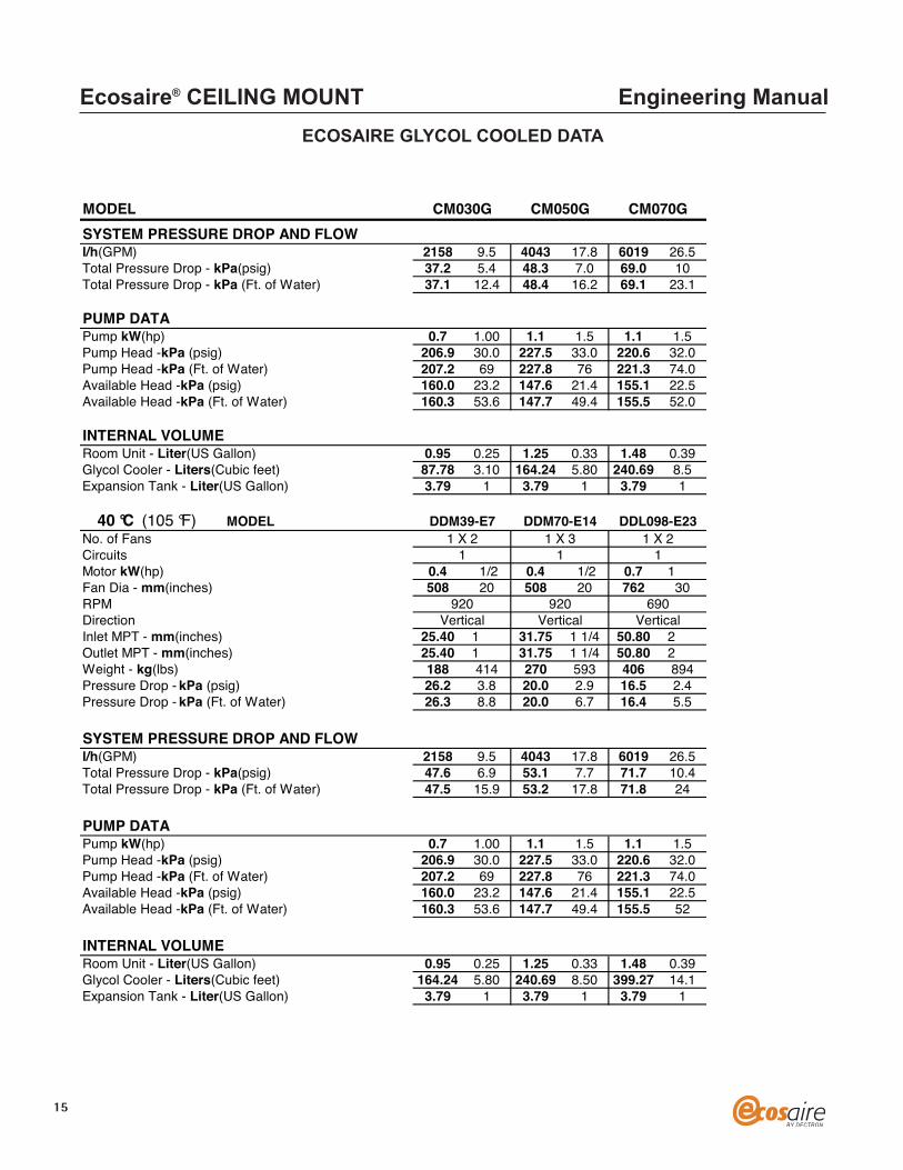
ECOSAIRE GLYCOL COOLED DATA

13
Ecosaire® CEILING MOUNT Engineering Manual
MODELHUMIDIFIERCapacity - Kg/h(lb./h) 4.5 10.0 4.5 10.0 4.5 10.0Capacity - kW
REFRIGERANT CONDENSERS - BRAZED PLATEQuantityMax. Ref. Working Pressure - BAR(psi) 27.6 400 27.6 400 27.6 400Max. Fluid Working Pressure - BAR(psi) 10.3 150 10.3 150 10.3 150
GLYCOL REGULATING VALVESTypeQtySize - mm(inches) 25.40 1 31.75 1 1/4 31.75 1 1/4
GLYCOL COOLED CONDENSER REQUIREMENTSRoom Unit35°C (95 °F) Ambientl/h(GPM) 2158 9.5 4043 17.8 6019 26.5Pressure Drop - kPa (psig) 21.4 3.1 33.1 4.8 55.2 8.0Pressure Drop - kPa (Ft. of Water) 21.2 7.1 33.2 11.1 55.3 18.5
3.4 3.4 3.4
CM030G CM050G CM070G
1 1 1
2-Way 2-Way 2-Way1 1 1
38°C (100 °F) Ambientl/h(GPM) 2158 9.5 4043 17.8 6019 26.5Pressure Drop - kPa (psig) 21.4 3.1 33.1 4.8 55.2 8.0Pressure Drop - kPa (Ft. of Water) 21.2 7.1 33.2 11.1 55.3 18.5
40°C (105 °F) Ambientl/h(GPM) 2158 9.5 4043 17.8 6019 26.5Pressure Drop - kPa (psig) 21.4 3.1 33.1 4.8 55.2 8.0Pressure Drop - kPa (Ft. of Water) 21.2 7.1 33.2 11.1 55.3 18.5
43°C (110 °F) Ambientl/h(GPM) 2158 9.5 4043 17.8 6019 26.5Pressure Drop - kPa (psig) 21.4 3.1 33.1 4.8 55.2 8.0Pressure Drop - kPa (Ft. of Water) 21.2 7.1 33.2 11.1 55.3 18.5
OVERALL UNIT DIMENSIONSLength - mm(inches) 838 33 1295 51 1295 51Height - mm(inches) 1905 75 1905 75 1905 75Width - Down Flow - mm(inches) 559 22 559 22 559 22
UNIT CONNECTION SIZESCondenser Inlet - (1/unit) MPT - mm(inches) 22.23 7/8 28.58 1 1/8 28.58 1 1/8Condenser Outlet - (1/unit) MPT - mm(inches) 22.23 7/8 28.58 1 1/8 28.58 1 1/8Humidifier - Compression - mm(inches) 6.35 1/4 6.35 1/4 6.35 1/4Condensate Drain - Hose - mm(inches) 22.23 7/8 22.23 7/8 22.23 7/8Condensate Pump - SAE Flare - mm(inches) 12.70 1/2 12.70 1/2 12.70 1/2Hot Water Reheat FPT In, MPT Out - mm(in) 12.70 1/2 12.70 1/2 12.70 1/2Weight - Approx. Kg(lb.) 350 770 389 855 420 925
ECOSAIRE GLYCOL COOLED DATA

Ecosaire® CEILING MOUNT Engineering Manual
MODELOUTDOOR GLYCOL (FLUID) COOLER SELECTIONDesign Ambient
GLYCOL COOLER DATAMODEL
No. of FansCircuitsMotor kW(hp) 0.4 1/2 0.4 1/2 0.4 1/2Fan Dia - mm(inches) 508 20 508 20 508 20RPMDirectionInlet MPT - mm(inches) 25.40 1 31.75 1 1/4 38.10 1 1/2Outlet MPT - mm(inches) 25.40 1 31.75 1 1/4 38.10 1 1/2Weight - kg(lbs) 112 246 178 391 198 435Pressure Drop - kPa (psig) 16.5 2.4 13.8 2.0 34.5 5Pressure Drop - kPa (Ft. of Water) 16.4 5.5 13.8 4.6 34.4 11.5
SYSTEM PRESSURE DROP AND FLOW
CM030G CM050G CM070G
Model Model Model35 °C (95 °F) DDM18-E6 DDM32-E13 DDM46-E1438 °C (100 °F) DDM25-E7 DDM42-E14 DDM70-E2140 °C (105 °F) DDM39-E7 DDM70-E14 DDL098-E2343 °C (110 °F) DDM49-E9 DDL081-F14 DDL141-E26
35 °C (95 °F) DDM18-E6 DDM32-E13 DDM46-E141 X 1 1 X 2 1 X 2
1 1 1
920 920 920Vertical Vertical Vertical
SYSTEM PRESSURE DROP AND FLOWl/h(GPM) 2158 9.5 4043 17.8 6019 26.5Total Pressure Drop - kPa(psig) 37.9 5.5 46.9 6.8 89.6 13Total Pressure Drop - kPa (Ft. of Water) 37.7 12.6 46.9 15.7 89.7 30
PUMP DATAPump kW(hp) 0.7 1.00 1.1 1.5 1.1 1.5Pump Head -kPa (psig) 206.9 30.0 227.5 33.0 220.6 32Pump Head -kPa (Ft. of Water) 207.2 69 227.8 76 221.3 74Available Head -kPa (psig) 160.0 23.2 147.6 21.4 155.1 22.5Available Head -kPa (Ft. of Water) 160.3 53.6 147.7 49.4 155.5 52
INTERNAL VOLUME Room Unit - Liter(US Gallon) 0.95 0.3 1.25 0.33 1.48 0.39Glycol Cooler - Liters(Cubic feet) 56.63 2.00 110.44 3.90 218.04 7.7Expansion Tank - Liter(US Gallon) 3.79 1 3.79 1 3.79 1
MODELNo. of FansCircuitsMotor kW(hp) 0.4 1/2 0.4 1/2 0.4 1/2Fan Dia - mm(inches) 508 20 508 20 508 20RPMDirectionInlet MPT - mm(inches) 25.40 1 50.80 2 38.10 1 1/2Outlet MPT - mm(inches) 25.40 1 50.80 2 38.10 1 1/2Weight - kg(lbs) 122 268 194 426 270 593Pressure Drop - kPa (psig) 15.9 2.3 15.2 2.2 13.8 2Pressure Drop - kPa (Ft. of Water) 15.8 5.3 15.2 5.1 13.8 4.6
38 °C (100 °F) DDM25-E7 DDM42-E14 DDM70-E211 X 1 1 X 2 1 X 3
1 1 1
920 920 920Vertical Vertical Vertical
14
ECOSAIRE GLYCOL COOLED DATA
15
Ecosaire® CEILING MOUNT Engineering Manual
ECOSAIRE GLYCOL COOLED DATA
MODELSYSTEM PRESSURE DROP AND FLOWl/h(GPM) 2158 9.5 4043 17.8 6019 26.5Total Pressure Drop - kPa(psig) 37.2 5.4 48.3 7.0 69.0 10Total Pressure Drop - kPa (Ft. of Water) 37.1 12.4 48.4 16.2 69.1 23.1
PUMP DATAPump kW(hp) 0.7 1.00 1.1 1.5 1.1 1.5Pump Head -kPa (psig) 206.9 30.0 227.5 33.0 220.6 32.0Pump Head -kPa (Ft. of Water) 207.2 69 227.8 76 221.3 74.0Available Head -kPa (psig) 160.0 23.2 147.6 21.4 155.1 22.5Available Head -kPa (Ft. of Water) 160.3 53.6 147.7 49.4 155.5 52.0
INTERNAL VOLUME Room Unit - Liter(US Gallon) 0.95 0.25 1.25 0.33 1.48 0.39Glycol Cooler - Liters(Cubic feet) 87.78 3.10 164.24 5.80 240.69 8.5Expansion Tank - Liter(US Gallon) 3.79 1 3.79 1 3.79 1
MODELNo. of FansCircuitsMotor kW(hp) 0.4 1/2 0.4 1/2 0.7 1
CM030G CM050G CM070G
40 °C (105 °F) DDM39-E7 DDM70-E14 DDL098-E23
1 1 11 X 2 1 X 3 1 X 2
Fan Dia - mm(inches) 508 20 508 20 762 30RPMDirectionInlet MPT - mm(inches) 25.40 1 31.75 1 1/4 50.80 2Outlet MPT - mm(inches) 25.40 1 31.75 1 1/4 50.80 2Weight - kg(lbs) 188 414 270 593 406 894Pressure Drop - kPa (psig) 26.2 3.8 20.0 2.9 16.5 2.4Pressure Drop - kPa (Ft. of Water) 26.3 8.8 20.0 6.7 16.4 5.5
SYSTEM PRESSURE DROP AND FLOWl/h(GPM) 2158 9.5 4043 17.8 6019 26.5Total Pressure Drop - kPa(psig) 47.6 6.9 53.1 7.7 71.7 10.4Total Pressure Drop - kPa (Ft. of Water) 47.5 15.9 53.2 17.8 71.8 24
PUMP DATAPump kW(hp) 0.7 1.00 1.1 1.5 1.1 1.5Pump Head -kPa (psig) 206.9 30.0 227.5 33.0 220.6 32.0Pump Head -kPa (Ft. of Water) 207.2 69 227.8 76 221.3 74.0Available Head -kPa (psig) 160.0 23.2 147.6 21.4 155.1 22.5Available Head -kPa (Ft. of Water) 160.3 53.6 147.7 49.4 155.5 52
INTERNAL VOLUME Room Unit - Liter(US Gallon) 0.95 0.25 1.25 0.33 1.48 0.39Glycol Cooler - Liters(Cubic feet) 164.24 5.80 240.69 8.50 399.27 14.1Expansion Tank - Liter(US Gallon) 3.79 1 3.79 1 3.79 1
Vertical Vertical Vertical920 920 690

16
Ecosaire® CEILING MOUNT Engineering Manual
ECOSAIRE GLYCOL COOLED DATA
MODELMODEL
No. of FansCircuitsMotor kW(hp) 0.4 1/2 0.7 1 0.7 1Fan Dia - mm(inches) 508 20 762 30 762 30RPMDirectionInlet MPT - mm(inches) 38.10 1 1/2 63.50 2 1/2 63.50 2 1/2Outlet MPT - mm(inches) 38.10 1 1/2 63.50 2 1/2 63.50 2 1/2Weight - kg(lbs) 206 453 483 1063 542 1192Pressure Drop - kPa (psig) 71.0 10.3 61.4 8.9 40.7 5.9Pressure Drop - kPa (Ft. of Water) 70.9 23.7 61.3 20.5 40.7 13.6
CM030G CM050G CM070G
1 X 2 1 X 2 1 X 3
920 690 690
43 °C (110 °F) DDM49-E9 DDL081-F14 DDL141-E26
Vertical Vertical Vertical
1 1 1
SYSTEM PRESSURE DROP AND FLOWl/h(GPM) 4611 20.3 8335 36.7 12423 54.7Total Pressure Drop - kPa(psig) 71.0 10.3 61.4 8.9 40.7 5.9Total Pressure Drop - kPa (Ft. of Water) 70.9 23.7 61.3 20.5 40.7 13.6
PUMP DATAPump kW(hp) 1.1 1.5 1.5 2.0 1.5 2.0Pump Head -kPa (psig) 275.8 40.0 239.9 34.8 269.6 39.1Pump Head -kPa (Ft. of Water) 275.1 92 239.2 80 269.1 90Available Head -kPa (psig) 204.8 29.7 178.6 25.9 228.9 33.2Available Head -kPa (Ft. of Water) 204.2 68.3 177.9 59.5 228.4 76.4
INTERNAL VOLUME Room Unit - Liter(US Gallon) 0.95 0.25 1.25 0.33 1.48 0.39Glycol Cooler - Liters(Cubic feet) 164.24 5.80 240.69 8.50 399.27 14.1Expansion Tank - Liter(US Gallon) 3.79 1 3.79 1 3.79 1
Expansion Tank sized for 100 Feet of piping run

17
Ecosaire® CEILING MOUNT Engineering Manual
MODEL
26.7°C (80 °F) DB / 19.5°C (67 °F) WB (50% RH)Total Capacity kW(Mbh) 16.8 57.4 32.3 110.4 45.5 155.3Net Sensible Capacity kW(Mbh) 11.2 38.1 21.2 72.5 30.2 103.1l/h(GPM) 2703 11.9 5172 22.8 7245 31.9Presure Drop -kPa (psig) 25.5 3.7 53.8 7.8 44.8 6.5Presure Drop -kPa (Ft. of Water) 25.4 8.5 53.8 18.0 44.9 15.0
23.9 °C (75 °F) DB / 17.0°C (62.5 °F) WB (50% RH)Total Capacity kW(Mbh) 11.7 39.8 22.5 76.7 31.9 108.8Net Sensible Capacity kW(Mbh) 9.3 31.9 17.8 60.8 25.6 87.4l/h(GPM) 1885 8.3 3634 16.0 5156 22.7Pressure Drop - kPa (psig) 13.1 1.9 27.6 4.0 31.7 4.6Pressure Drop - kPa (Ft. of Water) 12.9 4.3 27.8 9.3 30.8 10.3
22.2°C (72 °F) DB / 15.6°C (60 °F) WB (50% RH)Total Capacity kW(Mbh) 9.3 31.9 18.0 61.5 25.7 87.8Net Sensible Capacity kW(Mbh) 8.4 28.7 16.0 54.5 23.0 78.4l/h(GPM) 1544 6.8 2953 13.0 4202 18.5Pressure Drop - kPa (psig) 11.0 1.6 19.3 2.8 22.1 3.2Pressure Drop - kPa (Ft. of Water) 10.8 3.6 19.1 6.4 22.1 7.4
CM030C CM050C CM070C
FAN SECTION-L/S(CFM)-BELT-DRIVENAir Volume - L/S(CFM) 2549 1500 4842 2850 6796 4000Fan Motor kW(Hp) 0.6 0.75 1.1 1.5 2.2 3External Static - Pa(inches of water) 75 0.3 125 0.5 125 0.5Quantity of FansRPM
WATER REGULATING VALVEValve TypeValve Size - inches(mm) 19.05 0.75 25.40 1 25.40 1Valve Cv 14
CHILLED WATER COILFace Area -Sq m.( Sq Ft.) 0.3 3.6 0.6 6.4 0.8 8.3RowsFace Velocity -m/s(FPM) 2.1 416 2.3 444 2.4 480
HOT WATER REHEATCapacity - Kw(mbh) 10.7 36.6 19.4 66.2 19.4 66.2l/h(GPM), 82.2 °C (180 °F) EWT 454.2 2.0 681.4 3.0 681.4 3.0Pressure Drop - kPa (Ft. of Water) 26.9 9.0 26.9 9.0 26.9 9.0
ELECTRIC REHEAT, THREE-PHASETypeCapacity - kW(mbh) 5.9 20 11.5 39.3 11.5 39.3Number of Stages
1 1 11220 1066 899
3-Way 3-Way 3-Way
12 14
4 4 5
Fin-Tube Fin-Tube Fin-Tube
3 3 3
ECOSAIRE CHILLED WATER DATA

18
Ecosaire® CEILING MOUNT Engineering Manual
MODELFILTERSQuantity, 45% EffSize - mm-LxWxDSize - inches-LxWxD
HUMIDIFIERCapacity - Kg/h(lb./h) 4.5 10.0 4.5 10.0 4.5 10.0Capacity - kW
CM030C CM050C CM070C
1 2 2609x609x51 508x609x51 609x609x51
24x24x2 20x24x2 24x24x2
3.4 3.4 3.4
OVERALL UNIT DIMENSIONSLength - mm(inches) 838 33 1295 51 1295 51Height - mm(inches) 1905 75 1905 75 1905 75Width - Down Flow - mm(inches) 559 22 559 22 559 22
CONNECTION SIZESChilled Water Line - FPT - mm(inches) 19.05 3/4 25.40 1 25.40 1Chilled Water Outlet - FPT - mm(inches) 19.05 3/4 25.40 1 25.40 1Humidifier - Compression - mm(inches) 6.35 1/4 6.35 1/4 6.35 1/4Condensate Drain - Hose - mm(inches) 22.23 7/8 22.23 7/8 22.23 7/8Condensate Pump - SAE Flare - mm(inches) 12.70 1/2 12.70 1/2 12.70 1/2Hot Water Reheat FPT In, MPT Out - mm(in) 12.70 1/2 12.70 1/2 12.70 1/2Weight - Approx. Kg(lb.) 295 650 327 720 345 760
Units rated at 6.6°C (44 °F) EWT / 12.2°C (54 °F) L WT
ECOSAIRE CHILLED WATER DATA

19
Ecosaire® CEILING MOUNT Engineering Manual
Air Cooled, Water Cooled and Glycol CooledYES YES NO NOYES NO YES NO
MODEL AMPSFLA 18.8 18.8 15.0 9.8MCA 23 23 18 12MFS 25 25 20 15FLA 32.0 32.0 21.4 16.2MCA 39 39 26 20MFS 50 50 35 30FLA 39.9 39.9 29.3 24.1MCA 49 49 35 29MFS 60 60 50 45
Note: Maximum fuse size and maximum circuit breaker size are identical.
Chilled WaterYES YES NO NOYES NO YES NO
MODEL AMPSFLA 17.4 12.3 8.5 3.3MCA 22 15 11 4MFS 25 20 15 15FLA 25.7 20.5 9.9 4.7MCA 32 26 12 6MFS 35 30 15 15FLA 28.3 23.1 12.5 7.3MCA 35 29 16 9MFS 40 30 20 15
Note: Maximum fuse size and maximum circuit breaker size are identical.
380
CEILING MOUNTED UNIT
380380 380
ELECTRIC REHEAT
380 380
CM030
CM050
CM070
HUMIDIFIERPOWER SUPPLY
3 Phase 50 Hz
3803 Phase 50 Hz
CM030C
CM050C
CM070C
CEILING MOUNTED UNIT
ELECTRIC REHEATHUMIDIFIER
POWER SUPPLY380
ECOSAIRE ELECTRICAL DATA

20
Ecosaire® CEILING MOUNT Engineering Manual
PHASE/Hz 3 Phase 50 HzMODEL AMPS 380DCM18 FLA 1.3to MCA 1.6DCM28 MFS 15DCM32 FLA 2.6to MCA 2.9DCM39 MFS 15DCM63 FLA 3.9to MCA 4.2DCM70 MFS 15
FLA 4.0MCA 4.5MFS 15
Add 1.0 FLA and MCA when equipped with -40°C(-40°F) controls
PHASE/Hz 3 Phase 50 HzMODEL AMPS 380DDM18 FLA 1.3to MCA 1.6DDM25 MFS 15DDM32 FLA 2.6to MCA 2.9DDM49 MFS 15
FLA 3.9MCA 4.2MFS 15
DDL081 FLA 4.0to MCA 4.5DDL098 MFS 15
FLA 6.0MCA 6.5MFS 15
DRY COOLERS (GLYCOL)
DDL141
AIR COOLED CONDENSERS
DCL098
DDM70
ECOSAIRE ELECTRICAL DATA

1/2"
(12.
7m
m)T
HREA
DED
ROD
(CUS
TOM
ERSU
PPLI
ED) FI
LTER
RACK
237/
8"(6
06.4
mm
)
243/
16"
(614
.4m
m)
117/
8"(3
01.6
mm
)
NOTE
S:
1.AI
RDI
SCHA
RGE
AVAI
LABL
EIN
(4)L
OCAT
IONS
:RI
GHT,
BACK
,LEF
TAN
DBO
TTOM
.(F
RONT
OFUN
IT=
FILT
ERSI
DE)
2.BA
CKDI
SCHA
RGE
SHOW
N.
323/
16"
(817
.6m
m)
507/
16"(
1281
.1m
m)
63"(
1600
.2m
m)
24"
(609
.6m
m)
30"(
762
mm
)
101/
2"(2
66.7
mm
)
INFO
RMAT
ION
SUBJ
ECT
TOCH
ANGE
WIT
HOUT
PRIO
RNO
TICE
57"(
1447
.8m
m)
NOFI
LTER
RACK
FILTER RACK
Ecos
aire®
3-To
nUn
itDim
ensio
ns
Ecosaire® 3-TonUnit Dimensions
21
Ecosaire® CEILING MOUNT Engineering Manual
NO
TES:
1.AI
RD
ISCH
ARG
EAV
ALAB
LEIN
(4)L
OCA
TIO
NS
RIG
HT,B
ACK,
LEFT
AND
BOTT
OM
.(F
RON
TO
FU
NIT
=FI
LTER
SID
E)2.
BACK
DIS
CHAR
GE
SHO
WN
INFO
RMAT
ION
SUBJ
ECT
TOCH
ANG
EW
ITH
OU
TPR
IOR
NO
TICE

Ecosaire® 5-TonUnit Dimensions
22
1/2"
(12.
7m
m)T
HREA
DED
ROD
(CUS
TOM
ERSU
PPLI
ED) FI
LTER
RACK
237/
8"(6
06.4
mm
)
47"
(119
3.8
mm
)
155/
8"(3
96.9
mm
)
NOTE
S:
1.AI
RDI
SCHA
RGE
AVAI
LABL
EIN
(4)L
OCAT
IONS
:RI
GHT,
BACK
,LEF
TAN
DBO
TTOM
.(F
RONT
OFUN
IT=
FILT
ERSI
DE)
2.BA
CKDI
SCHA
RGE
SHOW
N.
513/
16"
(130
0.2
mm
)
537/
16"(
1357
.3m
m)
66"(
1679
.6m
m)
24"
(609
.6m
m)
49"(
1244
.6m
m)
131/
2"(3
42.9
mm
)
INFO
RMAT
ION
SUBJ
ECT
TOCH
ANGE
WIT
HOUT
PRIO
RNO
TICE
60"(
1524
mm
)NO
FILT
ERRA
CK
FILTER RACK
Ecos
aire®
5-To
nUn
itDim
ensio
ns
Ecosaire® CEILING MOUNT Engineering Manual
NO
TES:
1.AI
RD
ISCH
ARG
EAV
ALAB
LEIN
(4)
LOCA
TIO
NS
RIG
HT,B
ACK,
LEFT
AND
BOTT
OM
.(F
RON
TO
FU
NIT
=FI
LTER
SID
E)2.
ESTI
MAT
EDW
EIG
HT
=69
6LB
S3.
BACK
DIS
CHAR
GE
SHO
WN
1/2"
(12.
7m
m)T
HREA
DED
ROD
(CUS
TOM
ERSU
PPLI
ED) FI
LTER
RACK
247/
8"(6
31.8
mm
)
523/
4"(1
365.
3m
m)
183/
4"(4
76.3
mm
)
NOTE
S:
1.AI
RDI
SCHA
RGE
AVAI
LABL
EIN
(4)L
OCAT
IONS
:RI
GHT,
BACK
,LEF
TAN
DBO
TTOM
.(F
RONT
OFUN
IT=
FILT
ERSI
DE)
2.BA
CKDI
SCHA
RGE
SHOW
N.
583/
16"
(147
8m
m)
537/
16"(
1357
.3m
m)
66"(
1679
.6m
m)
28"
(711
.2m
m)
56"(
1422
.4m
m)
161/
8"(4
09.6
mm
)
INFO
RMAT
ION
SUBJ
ECT
TOCH
ANGE
WIT
HOUT
PRIO
RNO
TICE
60"(
1524
mm
)NO
FILT
ERRA
CK
FILTER RACK
Ecos
aire®
7-To
nUn
itDim
ensio
ns
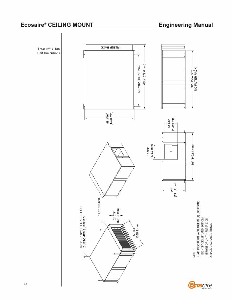
Ecosaire® 7-TonUnit Dimensions
23
Ecosaire® CEILING MOUNT Engineering Manual
NO
TES:
1.AI
RD
ISCH
ARG
EAV
ALAB
LEIN
(4)L
OCA
TIO
NS
RIG
HT,B
ACK,
LEFT
AND
BOTT
OM
.(F
RON
TO
FU
NIT
=FI
LTER
SID
E)2.
BACK
DIS
CHAR
GE
SHO
WN

Cabinet
Supply Blower Assemblies
Filter
Refrigeration System
ENGINEERING GUIDE SPECIFICATIONS
The computer-room air conditioning shall be a factory assembled (self-contained system) (split system) with a horizontal ducted air discharge and draw-through fans. The system shall bespecifically designed for computer room conditions and shall include a refrigeration circuit, (reheat section), (humidifier), belt-driven fans, microprocessor controls and all componentsnecessary for complete operation. It shall be designed to provide high sensible cooling during the normal cooling mode. It shall have a sensible capacity of ___ kW (___ Mbh) and a total capacitynot to exceed ___ Btuh, based on an entering air temperature of ___ °C (___ °F) dry bulb and___ °C(___ °F) wet bulb. It shall be capable of controlling room conditions to within + 1°C (+1°F) and + 2 percent RH.
STANDARD FEATURES
The cabinet shall be designed for horizontal air flow, with draw-through fans. The cabinet and frame shall be constructed of cold-rolled galvanized steel. The interior panel air surfaces andaccess panels shall be insulated with black-mat-coated fiberglass insulation. The access panels shall be easily removable for service. The unit shall require side service access only. All componentsmust be positioned for simple service and replacement. The electrical, compressor and humidifiercompartments shall allow inspection. All service connections shall be made through the side of the unit.
There shall be a multiple or single DWDI, forward-curved, belt-driven centrifugal blower(s)located in the draw-through position, for even air flow over the entire coil surface. Each blowershall be constructed of heavy-gauge corrosion-resistant steel and shall be statically and dynamicallybalanced before shipment. Each blower assembly shall be easily removable from the side of the unitwithout disturbing any other component. It shall be driven by a heavy-duty, drip-proof motor withClass B insulation and permanently lubricated ball bearings rated for the life of the unit. Eachblower motor shall have internal overload protection.
The filter frame shall be integral to the unit and shall allow for easy replacement from the frontof the unit. The filters shall be rated not less than 30 percent efficient by the ASHRAE 52-76 method.
The refrigeration system shall be completely factory assembled with type-L copper tubing and shall include a direct-expansion evaporator coil, solid-core filter/dryer, adjustable externallyequalized tx valve, manual-reset high-pressure switch, low-pressure switch, refrigeration servicevalves, sight glass/moisture indicator, refrigerant reclaim valve, liquid-line solenoid valve (air-cooledonly) and heat-pump-duty hermetic compressor. Water and glycol-cooled units shall include astainless steel brazed-plate refrigeration condenser and water regulating valve.
24
Ecosaire® CEILING MOUNT Engineering Manual

Evaporator Coil
Chilled-Water Coil(Chilled-Water Units)
High-EfficiencyCompressor
Electrical
Disconnect Switch
STANDARD FEATURES
The evaporator coil shall be constructed of seamless copper tubing expanded into aluminumfins. The coils shall be pressure tested to 10.3 BAR (150 psig). It shall be mounted in a corrosion-proof heavy-duty plastic drain pan. The coil shall be designed for 100 percent sensible coolingcapacity at 22.2°C (72°F) DB, 45 percent RH. It shall have a minimum face area of ___ m2 (___ ft2)and a maximum face velocity of ___m/s (___ fpm).
The chilled-water coil shall be constructed of seamless copper tubing expanded into aluminumfins. The coil shall be pressure tested to 10.3 BAR (150 psig). It shall be mounted in corrosion-proofheavy-duty plastic drain pan. It shall distribute water throughout the full face area, and shall befactory piped to a motorized, three-way*, proportional chilled-water valve rated at 27.6 BAR (400psig). The coil shall be designed for 100 percent sensible cooling capacity at 22.2°C (72°F) DB, 45%RH. It shall have a minimum face area of ___ m2 (___ ft2) and a maximum face velocity of ___m/s(___ fpm).
The Scroll compressor shall be rated for heat pump duty and shall be of a current high-efficiency design. It shall include inherent motor protection, anti-slug protection, oil strainer,crankcase heater, internal pressure relief, resilient suspension and quick-connect refrigeration service valves with gauge ports on suction and discharge lines. The compressor shall be serviceablewith the unit in operation without disturbing the performance or air flow.
The electrical panel shall be located out of the air stream to allow service while the unit is inoperation. All electrical components shall be located behind the access panel and shall contain allcircuit breakers, contactors, relays and transformers. Separate branch circuit breakers shall beprovided for the compressor, electric reheat, blower motor(s), controls and humidifier circuits.
A factory-mounted non-locking disconnect switch located in the high-voltage electricalsection shall be standard.
25
Ecosaire® CEILING MOUNT Engineering Manual

Supervisaire®Microprocessor
Controller
STANDARD FEATURES
All unit functions shall be controlled by the Supervisaire® microprocessor. The Supervisaire®shall be capable of controlling room conditions within the following parameters:
Temperature set point 4.4 to 29.4°C (40 to 85°F)Temperature control band 1 to 20°C (1 to 30°F)Humidity set point 40 to 80 percent rhHumidity control band 1 to 30 percent rh
The Supervisaire® control panel consists of six buttons for Program, Escape, Enter, Up and Downarrow and alarm access. A four-row, 20-character/row, alphanumeric LCD shall display all system-parameter setting screens, alarm-message screens, and system status screens. The parameters shall be set with the up and down buttons.
The alarms are:
The alarm memory shall save the data for all the last 50 alarms including the alarm message,time and date of occurrence, room temperature and humidity at occurrence. The battery backupshall protect and maintain the real-time clock. The batteries shall have an inactive life of eight toten years and an active life of six to eight years.
Adjustable sequential load activation shall allow the time delay between stages to be set inseconds in order to reduce inrush current and/or vary the response time.
26
• FIRE DETECTED• LOSS OF AIR FLOW-CHECK FAN• CHANGE AIR FILTERS• WATER DETECTED UNDER FLOOR• LOSS OF FLUID FLOW• HIGH FLUID TEMP• VOLTAGE ERROR• COMPRESSOR 1 HIGH PRESSURE• COMPRESSOR 2 HIGH PRESSURE• COMPRESSOR 1 LOW PRESSURE• COMPRESSOR 2 LOW PRESSURE• CUSTOMER ALARM• SPECIAL ALARM 1• EMERGENCY POWER ON• POWER RESTART• HIGH ROOM TEMPERATURE
• LOW ROOM TEMPERATURE• LOW ROOM HUMIDITY• HIGH ROOM HUMIDITY• HIGH COIL 1 TEMPERATURE• LOW COIL 1 TEMPERATURE• LOW COIL 2 TEMPERATURE• DISCHARGE TEMP SENSOR FAILURE• ROOM TEMPERATURE SENSOR FAILURE• ROOM HUMIDITY SENSOR FAILURE• WATER TEMPERATURE SENSOR FAILURE• COIL 1 TEMPERATURE SENSOR FAILURE• COIL 2 TEMPERATURE SENSOR FAILURE• CUSTOMER TEMPERATURE SENSOR FAILURE
Ecosaire® CEILING MOUNT Engineering Manual

Air-Controlled Condenser and Controls
Water-Cooled Condenser
Glycol-Cooled Condenser
Steam Humidifier
Electric Reheat
Hot-Gas Reheat
STANDARD FEATURES / INDIVIDUAL SYSTEMS
The unit shall be provided with a remote air-cooled condenser. It shall be sized to provide fullcooling capacity at 35, 38, 40 or 43°C (95, 100, 105 or 110°F) maximum ambient. The condensercasing, structural supports, coil frame and motor supports shall be constructed of 16-gaugegalvanized steel. The mounting legs shall be 10-gauge galvanized steel. The coil shall be constructedof copper coils expanded into aluminum fins, pressure tested to 31 BAR (450 psig). The fan bladeshall be aluminum, riveted to a zinc-plated steel hub. All motors shall be 0.4 kW (1/2 hp), single-speed. Motors shall be drip-proof with permanently lubricated and sealed ball bearings and inherentoverload protection.
The integral condenser controls shall include a contactor(s), control relay, variable speed fancontrol switch, and high and low-voltage terminal strips factory-wired in a weatherproof enclosure.The controls shall provide -26.9°C (-20°F) low ambient operation. The air-cooled condenser shall besized to provide the specified cooling capacity at a maximum outdoor ambient of ___°C (___°F).
WATER-COOLED
The water-cooled condenser shall be a heavy-duty, counterflow, brazed-plate heat exchanger.It shall be constructed of AISI-316 stainless-steel plates and shall be pressure tested at 39.3 BAR(570 psi). Maximum working pressure shall be 29.6 BAR (430 psi). It shall be fitted with a two-way,head-pressure-controlled, 10.3 BAR (150 psig), water-regulating valve.
GLYCOL-COOLED
The glycol-cooled condenser shall be a heavy-duty, counterflow, brazed-plate heat exchanger. It shall be constructed of AISI-316 stainless-steel plates and shall be pressure tested at 39.3 BAR(570 psi). Maximum working pressure shall be 29.6 BAR (430 psi). It shall be fitted with a two-way,head-pressure-controlled, 10.3 BAR (150 psig), water-regulating valve.
FACTORY-INSTALLED OPTIONS
The unit shall be fitted with a lattice-electrode steam humidifier. It shall provide particle-freesteam to the air stream without moisture carryover and shall be designed to operate on cold, hardwater. The electrodes shall be enclosed within a disposable plastic cylinder and shall not requirecleaning. Output capacity shall be adjustable from 10 to 100 percent and efficiency shall remainconstant throughout the life of the cylinder. Standard controls shall include an Auto/Off/DrainSwitch and a High-Water-Level Alarm Light. A built-in strainer shall be standard.
The unit shall be fitted with three-phase electric heating elements located at the coil discharge.They shall be constructed of spiral aluminum-coated steel fins brazed to a copper-coated steel tubeencasing the heating element, and shall be capable of withstanding moist conditions. The heatsection shall be capable of maintaining room dry-bulb temperature using 2, 3 or proportional stages of control. A U.L. approved high-limit safety switch shall prevent overheating.
A hot-gas reheat coil shall be furnished complete with three-way hot-gas valve and arefrigerant check valve. The coil shall be constructed of copper tubes expanded into aluminum fins.The hot-gas reheat coil shall maintain room temperature during the dehumidification cycle only.
27
Ecosaire® CEILING MOUNT Engineering Manual

Hot-Water Reheat
Dead-Front Disconnect Switch
Graphic Control Panel
Smoke Detector/Firestat
Underfloor Water Detector
Extended CompressorWarranty
Hot-Gas Bypass Valve
High-PressureWater-Regulating Valve
External Condensate Pump
FACTORY-INSTALLED OPTIONS
A hot-water coil shall be furnished to maintain room temperature. The coil shall be completewith two-way valve and Y-strainer. The coil shall be constructed of copper tubes expanded intoaluminum fins.
The unit shall be equipped with a factory mounted, non-locking dead-front disconnect switch.The operating lever shall protrude through the access panel and shall prevent opening the paneluntil switched off.
The remote graphic control panel shall be equipped with an advanced liquid-crystal display. It shall provide a graphic display of the temperature and humidity changes and shall feature aprogrammable schedule for any number of days or weeks as desired.
The unit shall be provided with a combination smoke detector and firestat that willautomatically shut the unit down and activate the alarm system.
The unit shall be provided with ___ (specify 2 to 4; 2 are standard) factory-installed electronicsensing probes to sense the presence of water under the floor and to activate the unit alarm. The sensors shall be factory wired to a ten-foot cable.
The unit shall include an extended one-year compressor warranty that provides for areplacement compressor. Extended warranty shall also be available as an option.
The unit shall be supplied with a hot-gas bypass valve to allow optimum unit operation at reduced heat load capacity condition.
WATER-COOLED
The unit shall be supplied with a two-way high-pressure water-regulating valve, rated at 20.7 BAR (300 psig) to allow unit operation at up to 20.7 BAR (300 psig) water pressure.
FIELD-INSTALLED ACCESSORIES
The unit shall be provided with a condensate pump rated at 121 l/h at 6.7 m (32 gph at 22 ft)head. It shall be complete with pump, motor, reservoir and float switch.
28
Ecosaire® CEILING MOUNT Engineering Manual

Low-Ambient Condenser
Remote Glycol Cooler
Glycol Control Package
Glycol Pump
Dual Pumps
Glycol Pump PackageAccessories Kit
AIR-COOLED
The unit shall be provided with a remote air-cooled condenser. It shall be sized to provide full cooling capacity at 35, 38, 40 or 43°C (95, 100, 105 or 110°F) maximum ambient. The condensercasing, structural supports, coil frame, and motor supports shall be constructed of 16-gaugegalvanized steel. The mounting legs shall be constructed of 10-gauge galvanized steel. The coil shallbe constructed of copper coils expanded into aluminum fins, pressure tested to 31 BAR (450 psig).The fan blade shall be aluminum, riveted to a zinc-plated steel hub. Fan motors shall be 0.4 kW (1/2hp). The motors shall be drip-proof with permanently-lubricated and sealed ball bearings andinherent overload protection. A factory installed three-way head-pressure control valve, a checkvalve, and an insulated, heated liquid receiver shall provide -40°C (-40°F) low-ambient operation.
The integral condenser controls shall include a contactor(s), control relay, and high and low-voltage terminal strips factory wired in the condenser’s weatherproof enclosure.
GLYCOL-COOLED
The glycol cooler shall be sized to provide the capacity specified at an outdoor ambient of___°C (___°F). The glycol cooler casing, structural supports, coil-frame and motor supports shall beconstructed of 18-gauge galvanized steel. The mounting legs shall be 16-gauge galvanized steel. The coil shall be constructed of seamless copper tubes expanded into aluminum fins and shall bepressure tested to 31 BAR (450 psig). The fan blade shall be aluminum riveted to a zinc-plated hub.Each motor shall be three-phase, drip proof with permanently lubricated and sealed ball andinherent overload protection.
The glycol cooler and pump control system shall be complete with fan contactor(s), controlrelay, fan-cycling temperature switch(s), and high and low-voltage terminal strips mounted inheavy-duty waterproof enclosures. The fan controls shall be factory mounted in an integralweatherproof enclosure.
The glycol circulating pump shall be 3600 RPM with a weatherproof TEFC NEMA rated motorwith inherent overload protection and a close coupled pump with a 416 stainless steel shaft. Thepump must be designed for continuous operation with glycol solution and must have high-headperformance characteristics. The pump size shall be selected in strict accordance with themanufacturer’s selection tables for proper operation.
The glycol pump kit shall include dual pumps with automatic change-over. The standby pumpshall automatically start upon failure of the lead pump and shall activate both a visual and audiblealarm on the indoor control panel. The control panel shall also include an alarm silence switch,primary-pump selector switch and pump-run indicator lights. A flow switch shall be supplied.
The system shall be provided with an enclosure for the pump starter, plus an expansiontank kit and air purger with automatic air vent for field installation. Check valves shall be provided with dual pump installation.
29
Ecosaire® CEILING MOUNT Engineering Manual
FREE-COOL IS A GLYCOL-C
30
Ecosaire® CEILING MOUNT Engineering Manual

Ecosaire® CEILING MOUNT Engineering Manual
USA & CANADA1.800.387.19301.800.800.1868
10898 Crabapple Rd.Suite 103Roswell, Georgia USA 30075
2180 Dunwin Drive, Unit 7Mississauga, ON Canada L5L 1C7
3999 Cote VertuMontreal, QC Canada H4R 1R2
Fax: 905.828.5018www.ecosaire.come-mail: [email protected]
designer indoor airTM
Ecosaire® customers include:Bell CanadaCanada PostCanopy GroupCarleton UniversityCanadian PacificCanadian ParliamentCisco SystemsCity of TorontoDept. of National Defencee-SpireEricssonIBMImperial OilIntelJanus FundsJD EdwardsMCIMitelNortelOntario HydroPoudre Valley HospitalSprintTCITelesat CanadaUniversity of QuébecU.S. Air ForceWestwind Media
Dectron reserves the right to make any changes in the design or specification of any product at any time without notice.
© Copyright 2004 by Dectron Printed in Canada LIT00113-EDCM50-0308-0K