Embed Size (px)
Citation preview
PRECISION OPTICAL FIBER ALIGNMENT
STRUCTURES
www.optoscribe.com
Optoscribe Limited 2019
The demand for ever increasing bandwidth is driving the need for dense fiber optical connections in applications such as datacentre interconnects and optical switching nodes. Many of these high-density connections require the use of precise, tightly toleranced fiber alignment structures to accurately position the optical ports. While many solutions exist to create one-dimensional arrays of optical fibers such as v-groove arrays, making 2D arrays of optical fibers is more complex.2D hole arrays to house and position arrays of fibers can be used in a wide range of applications, ranging from multi-fiber connectors to large arrays for interfacing to optical switching hardware such as reconfigurable optical add drop multiplexers (ROADMs).
Clearly, tight tolerances are critical to achieving low loss connections, particularly for single-mode applications. The key sources of coupling loss are due to fiber-core offset, fiber-axis tilt, fiber-end separation and mode field mismatch.
In the case of MT/MPO-type connectors, fiber-core offset is the dominant loss contributor and is caused by the achieved manufacturing tolerances of the fibers, fiber ferrules and MT pin holes.
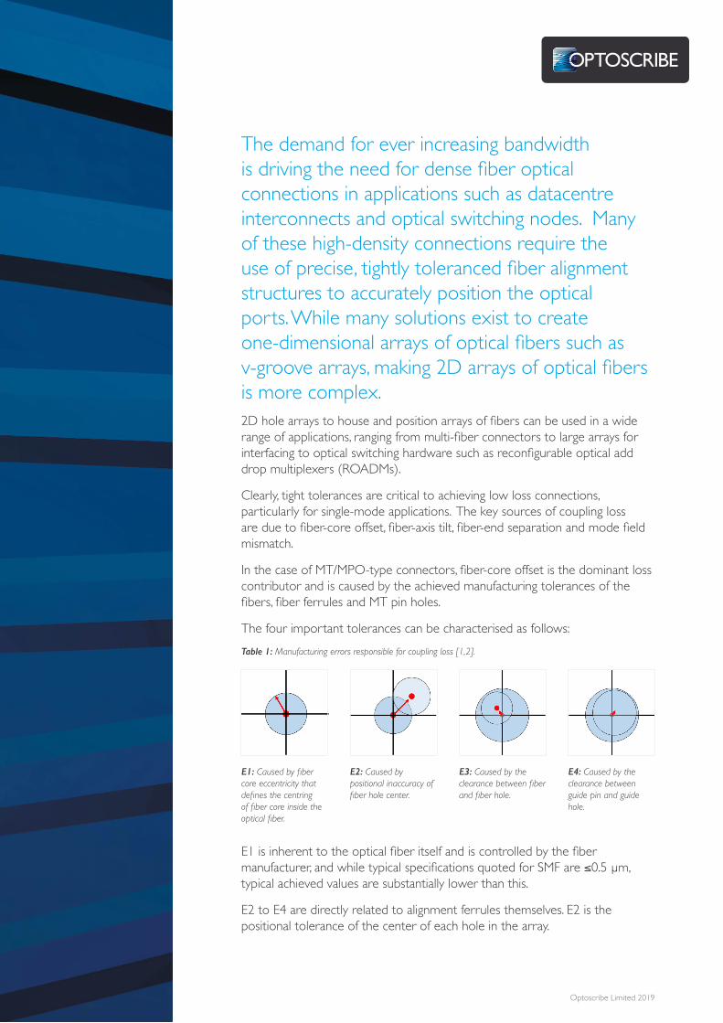
The four important tolerances can be characterised as follows:Table 1: Manufacturing errors responsible for coupling loss [1,2].
E1 is inherent to the optical fiber itself and is controlled by the fiber manufacturer, and while typical specifications quoted for SMF are ≤0.5 µm, typical achieved values are substantially lower than this.
E2 to E4 are directly related to alignment ferrules themselves. E2 is the positional tolerance of the center of each hole in the array.
E1: Caused by fiber core eccentricity that defines the centring of fiber core inside the optical fiber.
E2: Caused by positional inaccuracy of fiber hole center.
E3: Caused by the clearance between fiber and fiber hole.
E4: Caused by the clearance between guide pin and guide hole.
Optoscribe Limited 2019
The higher the deviation from its nominal position, the greater the contribution towards optical signal loss. E3 is due to the diameter tolerances on the holes creating clearance between the fiber and the walls of the hole. E4 is similar to E3 but is caused by the clearance between guide pins and guide holes for alignment purposes.
In addition, there are other considerations which affect the final positional accuracy of the fibers. The ability to control the diameter and sidewall angle tightly throughout the volume of the hole is important to maintaining repeatable lateral and angular fiber positioning.
Glass is widely used in photonics due to its inherent thermal and mechanical stability, and its optical performance. When used for fiber alignment purposes, glass can be chosen to have appropriate CTEs for a specific application, e.g. matched to Silicon for interfacing to Silicon Photonics, or minimised for low alignment variance in fiber to free space coupling applications such as ROADMs.
2D micro hole arrays can be fabricated using various techniques such as molding, lithographic approaches, CNC milling, ultrasonic drilling, and also using a range of laser-based processes.
Molding is commonly used for multi-fiber ferrules and can be used to manufacture tightly-toleranced hole arrays. This process however has some significant limitations in material choices due to the requirement for injection molding, and whilst glass-filled epoxies are used to bring the CTE closer to the inherent expansion coefficient of the glass, there is still a significant mismatch for applications such as direct coupling to silicon photonics.
A range of lithographic techniques can be used to manufacture precision hole arrays with high levels of positional accuracy, however controlling absolute hole diameters, sidewall angles and geometric profile throughout the depth of the material can be a significant challenge.
CNC milling can also be used to fabricate holes, however, this technique suffers from tolerancing and tooling limitations especially in achieving the desired aspect ratios for smaller holes, and it is relatively slow in brittle materials such as glass.
Laser machining comes in many forms, is flexible and able to cope with a wide range of hole sizes. Laser ablation is commonly used to drill holes in many types of material at high speed, however limitations exist on tolerancing and controlling diameters and aspect ratios throughout the length of the hole.
An alternate laser machining approach is the use of laser induced selective etching. This two-stage micro-structuring process relies on using a focussed ultrashort pulsed laser to induce sub surface patterning of the material, localised to the focus of the laser beam. By rapidly scanning a 3D shape within the glass, regions of enhanced etch rate are created, such that upon exposing the substrate to a wet chemical etch, the irradiated regions etch preferentially. This approach has the benefit of full 3D flexibility in the patterning and can create high precision, highly controllable microstructures in glass.
Optoscribe Limited 2019
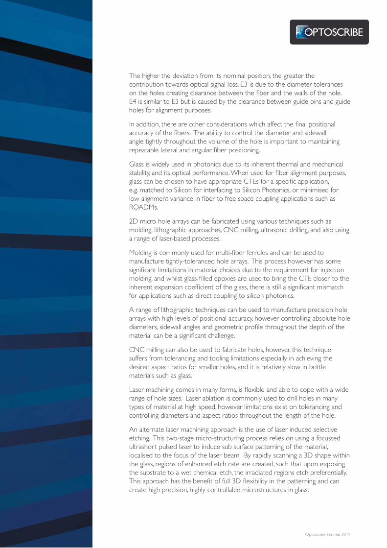
The speed of ultrafast direct laser writing allows for a production capacity of well over 50 million precision fiber alignment holes per year per laser machine. The wet etch process used is a standard semiconductor style process and so is inherently scalable.Using laser induced selective etching provides a tight control over E2 to E4 during micromachining of hole arrays. In addition, the 3D control provides the ability to shape the hole entrance creating a funnel or conical taper to allow for easy insertion of the fibers. Holes can also be formed at arbitrary angles to the surface of the glass such as the 8 degrees typically used for minimising back-reflections. An example is shown in figure 1 below.
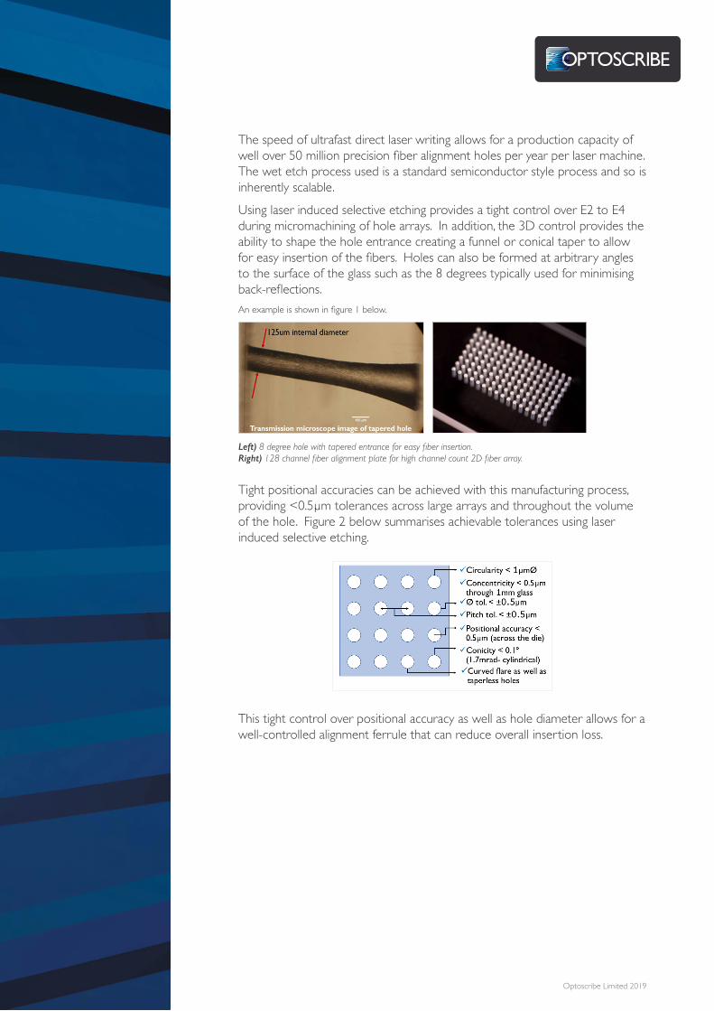
Tight positional accuracies can be achieved with this manufacturing process, providing <0.5µm tolerances across large arrays and throughout the volume of the hole. Figure 2 below summarises achievable tolerances using laser induced selective etching.
This tight control over positional accuracy as well as hole diameter allows for a well-controlled alignment ferrule that can reduce overall insertion loss.
Left) 8 degree hole with tapered entrance for easy fiber insertion. Right) 128 channel fiber alignment plate for high channel count 2D fiber array.

Optoscribe Limited 2019
About Optoscribe LtdFormed in 2010, Optoscribe uses its innovative laser direct write technology to manufacture glass-based photonic components primarily for the telecommunications and data communications markets. Optoscribe’s technology allows for 3D waveguide formation and 3D laser induced selective etching with unprecedented design freedom.
Optoscribe’s Precision Fiber Alignment Structures (OptoArray™) are capable of solving many of the challenges with the drive for high density optical connections.
The company is located in Livingston, UK, where it has a state-of-the-art manufacturing facility.
References:[1] Suematsu, Katsuki, et al. “Super low-loss, super high-density multi-fiber optical connectors.” Furukawa review 23 (2003): 53-58.
[2] Kihara, Mitsuru. “Novel MT/MPO Single-Mode Multifiber Connector Technologies for Optical Fiber Communications.” Optical Fiber and Wireless Communications (2017): 233.

Optoscribe Limited Rosebank Technology ParkRosebank RoadLivingstonEH54 7EJUnited Kingdom
T: +44 (0) 1506 536000E: [email protected]: www.optoscribe.com
For further information please contact us, details below