Embed Size (px)
Citation preview
Precision Variable Frequency Drive for an AC Synchronous Motor
Design Report May07-13 Jim Walker
Prof. Ajjarapu
By Dave Reinhardt
Jason Kilzer Matt Shriver Nick Nation
DISCLAIMER: This document was developed as a part of the requirements of an electrical and computer engineering course at Iowa State University, Ames, Iowa. This document does not constitute a professional engineering design or a professional land surveying document. Although the information is intended to be accurate, the associated students, faculty, and Iowa State University make no claims, promises, or guarantees about the accuracy, completeness, quality, or adequacy of the information. The user of this document shall ensure that any such use does not violate any laws with regard to professional licensing and certification requirements. This use includes any work resulting from this student-prepared document that is required to be under the responsible charge of a licensed engineer or surveyor. This document is copyrighted by the students who produced this document and the associated faculty advisors. No part may be reproduced without the written permission of the senior design course coordinator.
November 8, 2006
i
Table of Contents 1.0 Introductory Material .................................................................................................... 1
1.1 Abstract ..................................................................................................................... 1 1.2 Acknowledgments..................................................................................................... 1 1.3 Problem Statement .................................................................................................... 1 1.4 Operating Environment............................................................................................. 2 1.5 Intended User and Uses ............................................................................................ 2 1.6 Assumptions and Limitations ................................................................................... 2
1.6.1 Assumptions....................................................................................................... 2 1.6.2 Limitations ......................................................................................................... 2
1.7 Expected End Product and Other Deliverables......................................................... 3 2.0 Approach and Product Design Results ......................................................................... 3
2.1 Approach................................................................................................................... 4 2.1.1 Design Considerations ....................................................................................... 4 2.1.2 Functional Requirements ................................................................................... 4 2.1.3 Design Considerations ....................................................................................... 5 2.1.4 Technology Considerations ............................................................................... 6 2.1.5 Technology Approach Considerations............................................................... 6 2.1.6 Testing Requirements Considerations ............................................................... 6 2.1.7 Future Plan ......................................................................................................... 7
2.2 Product Design Results ............................................................................................. 8 2.2.1 Power Source ..................................................................................................... 8 2.22 AC to DC Converter ........................................................................................... 8 2.2.3 Pulse Width Modulator ...................................................................................... 9 2.2.4 Low Pass Filter ................................................................................................ 11 2.2.5 Frequency Counter........................................................................................... 11 2.2.6 Voltage Amplifier ............................................................................................ 11 2.2.7 Strobe Light System......................................................................................... 12
3.0 Resource Requirement ................................................................................................ 13 3.1 Personal Effort ........................................................................................................ 13 3.2 Other Resource Requirements ................................................................................ 13 3.3 Financial Requirements .......................................................................................... 14 3.4 Schedules ................................................................................................................ 15
4.0 Closure Materials ........................................................................................................ 15 4.1 Project Team Information....................................................................................... 17 4.2 Closing Summary.................................................................................................... 18 4.3 References............................................................................................................... 19
Appendix A……………………………………………………………….……………..20
ii
List of Figures
Figure 1: Complete Block Diagram of Precision Variable Frequency Drive 8 Figure 2: Block Diagram of Pulse Width Modulator 9 Figure 3: Schematic of DC Signal Generator 9 Figure 4: Triangle Waveform Generator 10 Figure 5: Generated Output from the Comparator 10 Figure 6: Comparator Schematic 10 Figure 7: Schematic of Low Pas Filter 11 Figure 8: Frequency Counter 11 Figure 9: Amplifier 11 Figure 10: Strobe Light Schematic (Vinyl Engine) 12 Figure 11: The strobe light shinning on the special disc. (Vinyl Engine) 12 Figure 12: Deadlines Chart 15 Figure 13: Detailed Gantt Chart 16
iii
List of Tables Table 1: Output Voltage vs. Changing R4 Value 9 Table 2: Part List for Strobe Light 12 Table 3: Personal Effort of the Group 13 Table 4: Other Resources 13 Table 5: Financial Requirements 14
1
1.0 Introductory Material In the following sections the precision variable frequency drive design project will be defined, where and who this type of project is for, and what the expected end product will be.
1.1 Executive Summary Synchronous motors are motors that run at a specific speed. A customer may want to run the motor at different speeds, like for a record player that needs to operate at 45 and 33 1/3 rpm. A precision variable frequency drive is a way to speed up or slow down the motor by changing the frequency of the input voltage. This product will be designed to adjust the frequency between 58 to 62 hertz by the turning of a dial. The digital display will be accurate up to the thousandth of a hertz. In addition, a strobe light will allow the user to observe the rpm of the motor. The precision variable frequency drive will have a long term drift that allows for a gradual decrease/increase of speed that allows for more accurate tuning.
1.2 Acknowledgments Jim Walker deserves much thanks for his assistance to us in this project. His equipment, technical advice, and financial aid are essential for the success of this project. Prof. Ajjarapu’s technical support throughout this project will help ensure the integrity of the project and better understanding for the group.
1.3 Problem Statement The general problem is the ability of a record player to keep a specific speed. The synchronous motor used on a record player is supposed to play the record at a specific speed. However, the motor does not always run at the specified speed which causes the record to sound out of pitch. A precision variable frequency drive will provide a constant frequency to the synchronous motor which in turn will maintain a constant speed of the record table. The general solution to the above mentioned problem is creating a precision variable frequency drive. The precision variable frequency drive will allow the user to manually change the frequency using a dial. The drive will also have a LCD screen displaying the frequency.
2
1.4 Operating Environment The operating environment for the precision variable frequency drive will be indoors in use with a record player. Therefore it will not be subject to outdoor weather or extreme temperatures. Extreme dust will also not be an issue because the device will be covered.
1.5 Intended User and Uses Users of this precision variable frequency drive need to also be owners of a record turntable. A user of this product would have to be an avid music listener because for the casual listener, the change in pitch created by a turntable running at an incorrect speed would not be important. The user would expect precision with this product, because it is the lack of precision of standard power feed to the turntable motor that would drive a person to purchase it. The user will be assumed to be a lay person, thus no special knowledge will be required to operate the variable frequency drive. It can also be assumed that the user would be familiar with record turntables; otherwise they would not have purchased the product. This variable frequency drive is intended to be used with a record turntable. The device will feed power to the motor that turns the record table. It will also provide precise control of the speed of the record turntable. The variable frequency drive should not be used for any other purpose.
1.6 Assumptions and Limitations
The following is a list of assumptions and limitations that was developed for the precision variable frequency drive.
1.6.1 Assumptions This is list of what the senior design group needed to assume to complete this project.
• Constant linkage – the belt connecting the motor to the turntable is constant. Basically, an increase in motor speed by a certain factor will result in an increase in the speed of the turntable by the same factor.
• Input Voltage – the input voltage will be a standard household outlet of 120 V at sixty hertz single phase.
• Plug – the plug from the record player can plug into a standard three pronged outlet.
3
1.6.2 Limitations This section shows the design constraints that will define the precision variable frequency drive project.
• Precision – the precision variable frequency drive will be accurate to .001 Hertz. • Price – the total end product cost must be less than $1,000. • Frequency Range – 58 to 62 Hertz with step of 0.1 Hertz. • Voltage Range – 110 to 135 Volts. • Stability – the precision variable frequency drive must be stable. Short term
stability of less that +/- 0.01%. It shall not be affected by fluctuations in incoming voltage or frequency.
• Power Output – 75 W minimum.
1.7 Expected End Product and Other Deliverables The end product of the senior design project is to have designed a precision variable frequency drive for an AC synchronous motor. In addition to the precision variable frequency drive the group will have designed a portable strobe light system that can be used to measure the motor’s exact rpm rate. The intended use for the product is to deliver power to the synchronous AC motor of a high-end, belt-driven record turntable. Using the drive will enable the listener to tune the turntable to exactly the desired pitch. A portable strobe light system will be delivered in addition to the precision variable frequency drive. The strobe light will be adapted to read the turntables exact rpm rate enabling the listener to measure the rpm of the turntable. The precision variable frequency drive and portable strobe light system will be developed into a prototype at the ready to manufacture level. The expected delivery date for the product is May 2007.
2.0 Approach and Product Design Results This section will detail our approach to solving the problem of creating a precision variable frequency drive and a portable strobe light system, and a description of our design.
4
2.1 Approach The following section details our approach to solving our design of the precision variable frequency drive.
2.1.1 Design Considerations The design considerations that were taken into account for the precision variable frequency drive are:
1. The precision variable frequency drive must be accurate to .001 Hz 2. Adjustable from 58-62 Hz by .1step 3. Includes a strobe light system that measures the frequency accurately to .1hz 4. Operate at a power output of minimum 75 W 5. Must be have short-term stability of .001%
The turn-table motor frequency controller will allow the user to adjust the motor frequency that is fed into the turn-table. Not all turn-table motors operate at a perfect 33 1/3 RPM or 45 RPM due to the inaccuracy of tuning and not being able to see the exact frequency, which causes the record to sound out of pitch. A digital read-out will also need to be developed for the precision variable frequency drive. It will need to display a frequency between 58 and 62 Hz. The digital read-out will be accurate to three decimal places. The precision variable frequency drive will have a knob controller in which the frequency can be adjusted. The frequency needs to be adjustable from 58 to 62 Hz, with a step of .1 Hz. A portable strobe system will also be developed to measure the motors exact RPM rate. The strobe system will allow the user to make sure that the motor is operating at exactly 33 1/3 or 45 RPM. It will also need to display the motor’s exact RPM. The turn-table motor frequency controller will allow the user to adjust the frequency that the turn-table is fed. This will allow the user to change the pitch of the record playing. The turn-table motor frequency controller needs to be very accurate with long-term(drift) and short-term stability of less than +/-0.01%.
2.1.2 Functional Requirements The functional requirements for the variable frequency drive include:

5
1. Asynchronous motor frequency controller 2. Portable strobe system 3. Knob controller to adjust frequency 4. Digital read-out of frequency The turn-table motor frequency controller will allow the user to adjust the motor frequency that is fed into the turn-table. Not all turn-table motors operate at a perfect 33 1/3 RPM or 45 RPM due to the inaccuracy of tuning and not being able to see the exact frequency, which causes the record to sound out of pitch. The turn-table motor frequency controller will allow the user to adjust the frequency that the turn-table is fed. This will allow the user to change the pitch of the record playing. The turn-table motor frequency controller needs to be very accurate with long-term(drift) and short-term stability of less than +/-0.01%. A portable strobe system will also be developed to measure the motors exact RPM rate. The strobe system will allow the user to make sure that the motor is operating at exactly 33 1/3 or 45 RPM. It will also need to display the motor’s exact RPM. The precision variable frequency drive will have a knob controller in which the frequency can be adjusted. The frequency needs to be adjustable from 58 to 62 Hz. A digital read-out will also need to be developed for the precision variable frequency drive. It will need to display a frequency between 58 and 62 Hz. The digital read-out will be accurate to three decimal places.
2.1.3 Design Considerations The design considerations for the precision variable frequency drive will include: 1. Maximum weight and size 2. Minimum power output 3. Minimum operating frequency The first design consideration is the size of the precision variable frequency drive. The final product will need to be small enough to be put next to a turn-table without taking up too much room. It needs to be visually appealing and not too big. It should not be much bigger than 2’x 1’x .5’ in size and not weigh more than 5 lbs. The precision variable frequency drive will need to output a minimum of 75 Watts of power. It will need to be fed by a standard 120 V wall outlet and provide a minimum of 75 Watts to the turn-table. The minimum operating frequency will also need to be taken into account when designing the precision variable frequency drive. It will need to be able to operate at
6
lower frequencies in the 58-62 Hz range. The pulse width modulator, which will allow the user to adjust the frequency, will need to be stable at these lower frequencies.
2.1.4 Technology Considerations The group considered two technologies to change the frequency of the incoming power. The group decided to use pulse width modulation instead of a quartz crystal The pulse width modulator will allow the user to adjust the operating frequency of the motor. The advantages of using a pulse width modulator are the low power loss and the pulsing action will run at a much lower speed than an equivalent steady voltage. The disadvantages of using a pulse width modulator are some audible noise and the modulator is said to put stress on the motor bearings, shortening its life.
2.1.5 Technology Approach Considerations The technology approach considerations that will need to be considered are what the client would like the precision variable frequency drive to do, an analysis of how to make it work, and prototyping. While doing analysis of how a variable speed drive works, the following block diagram was established: This block diagram will be the basis for the precision variable frequency drive. The half wave rectifier will change the input AC voltage into a DC voltage. The pulse width modulator will allow a user to change the frequency of the input voltage. A wave shaper will change the DC voltage back into an AC voltage and the amplifier will step the voltage back up to a voltage that will be able to feed the record player.
2.1.6 Testing Requirements Considerations The precision variable frequency drive will need to be tested throughout the design process. This testing will include the testing of each part in the design. Testing will be necessary for each individual design part as well as the precision variable frequency drive when it is completely put together. The first test will be of the half-wave rectifier. This will be the first component of the design that will be made and it will need to be tested first. The half-wave rectifier will take an AC Voltage from the wall and turn it into a DC voltage. The rectifier will be tested using an oscilloscope. The group will test the rectifier by looking at the output voltage on an oscilloscope. If the rectifier turns the AC voltage in a DC voltage, it will pass the test.
7
The second part of the design that will be tested is the pulse width modulator. The modulator will allow the user to adjust the frequency of the output voltage. The team will test this component using a frequency counter or an oscilloscope. The group will hook the frequency counter up to the output voltage of the pulse width modulator and determine if the group is able to adjust the frequency accurately by adjusting a potentiometer in the circuit. The group will need to make sure that pulse width modulator will adjust to a frequency of 58 to 62 Hz within .001Hz. The pulse width modulator will pass the test if it can adjust the frequency accurately. The next component that will need to be tested is the wave-shaper. This component will change the DC voltage back into an AC voltage. The group will test this component using an oscilloscope. The output voltage on the oscilloscope will be tested and it will pass the test when a clean AC voltage is produced from a DC input voltage. The strobe light system will also need to be tested. The system will be tested by comparing it to a source known to rotate at the required rpm. The precision variable frequency drive will need to be tested when it is completed. The group will need to make sure that the Precision variable frequency drive meets all of the functional requirements set forth. The group will need to make sure that it outputs a minimum of 75 Watts, it will need to allow the user to adjust the input frequency from 58 Hz to 62 Hz, accurate to 0.001 Hz. It will need to operate the motor at a frequency accurate to .001%. The strobe light system will need to be able to measure the motors exact RPM rate accurate to 0.01%.
2.1.7 Future Plan Upon review of the detailed project design, it has been decided to continue the project as planned. It will be continued as scheduled because the detailed design will meet the design objectives. The design has been modeled in Pspice and Matlab and detailed outputs have been produces. After reviewing these models and outputs, it has been decided to continue as scheduled. Time and money were also considered and the design is under the budget for both.

8
Figure 1: Complete Block Diagram of Precision Variable Frequency Drive
2.2 Product Design Results The design of the precision variable frequency drive started out with the decision of what technology should be used. The group decided to use pulse width modulation technology to change the frequency of the power outputted. Figure 1 shows the parts that will make up the precision variable frequency drive. It should be noted that the parts within the dotted line have been designed by the group.
The next portion of this report is will describe each one of the blocks shown in Figure 1. The first block is the AC power source.
2.2.1 Power Source This is the power that is provided from a wall outlet. This power is expected to be continuous AC 120 Volt, 60 Hz. The problem with the power from the wall is that the frequency, 60 Hz., is not exactly constant. The power leaves the wall and enters the precision variable frequency drive. Once in the precision variable frequency drive the AC power is converted into DC power.
2.22 AC to DC Converter The AC to DC converter will take in 120 VAC and produce 12 Volt DC. The project team will purchase this component. The group is going to purchase a converter of the same type that a cell phone charger would use. The converter is around $20 to purchase. After the power has been changed into DC pulse width modulation can take place.

9
Figure 2: Block Diagram of Pulse Width Modulator
R4
150k
U1
uA741
3
2
74
6
1
5+
-
V+
V-
OUT
OS1
OS2
0
0
0
V1
-12Vdc
V3
12Vdc
0
R2
68k
V5
12Vdc
Figure 3: Schematic of DC Signal Generator
2.2.3 Pulse Width Modulator The brain of the precision variable frequency drive is the pulse width modulator. Pulse width modulation (PWM) is uses to control and change the frequency of the outputted. The PWM will provide control of the frequency down to the nearest one-hundredth of a Hertz. Figure 2 shows the parts of the PWM along with the waveform that each one generates.
The two blocks on the left side are very important because their output greatly affect the output of the PWM. The top block takes a DC source and outputs a DC signal that can be controlled through the changing of the resistance of a potentiometer. The ability to change the DC voltage is actually the control mechanism that will be used to change the frequency of the output voltage. Figure 3 shows the schematic that is being used for creating the DC signal. Table 1 shows the reference voltage changing depending on the potentiometer.
Table 1: Output Voltage vs. Changing R4 Value
R4 Value Output Voltage 50k 8.772 V 100k 6.913 V 150k 5.703 V
10
R1
1k
0
V2
-15Vdc
R2
100k
U1
uA741
3
2
74
6
1
5+
-
V+
V-
OUT
OS1
OS2
V3
15Vdc
0Figure 6: Comparator
Schematic
-
+
U5A
1458
3
21
84
-
+
U6A
1458
3
21
84
V3
5Vdc
R10
100k
0
V2
5Vdc
R9
1k
C3
1n
0
0
0
Triangle Output
R1
47kV1
12Vdc
0
Figure 4: Triangle Waveform Generator
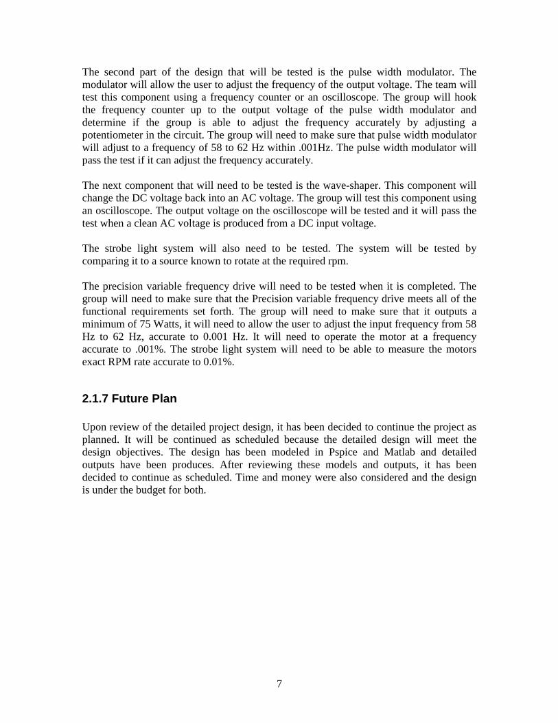
The triangle waveform block in Figure 2 takes a DC signal and produces a triangle waveform. Figure 4 shows the schematic that the group designed to produce the triangle waveform. The comparator is then used to compare the triangle waveform to the reference DC signal. When the triangle wave is greater than the DC value the comparator will saturate high and when the converse is true the comparator will saturate low. Figure 6 shows the schematic of the comparator that will be built, it should be noted that DC signal connects to the negative terminal and the triangle waveform connects to the positive terminal of the op amp.
Figure 5: Generated Output from the Comparator
11
Vout
R1
33
C1
47u
Vin
Figure 7: Schematic of Low Pas Filter
Figure 8: Frequency Counter
U1
OPAMP
+
-
OUT
V112Vdc
R1
1k
R2
9k
0
0
Figure 9: Voltage Amplifier
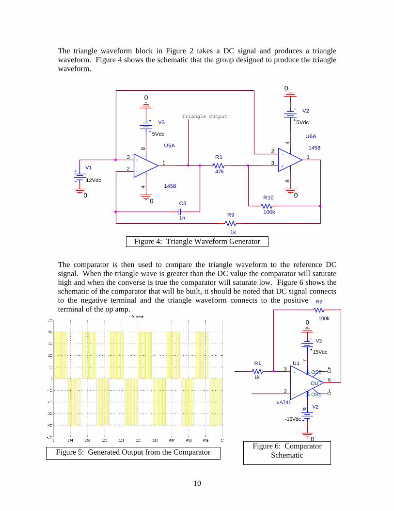
2.2.4 Low Pass Filter The output from the comparator goes through a low-pas filter that will filter out the higher order harmonics. When the output waveform shown in Figure 5 is passed through a low pass filter the higher order harmonics are filtered out. The filtering out of the higher order harmonics will produce a sinusoid. Figure 7 shows a schematic of the low pass filter that will be used.
2.2.5 Frequency Counter A frequency counter will connect to the circuit after the low pass filter and measure the frequency of the AC signal being outputted to the voltage amplifier. This device will display the frequency of the power it is sampling on a LCD screen. Figure 8 shows a picture of the frequency counter that will be purchased.
2.2.6 Voltage Amplifier After the frequency is changed with the PWM, the sine wave will need to be stepped back up to 120 VAC. To step the 12 VAC signal to 120 VAC, a non-inverting amplifier will be used. This gain amplifier will use an operational amplifier and two resistors to provide the needed gain. The gain that will be needed is 10. The values for the resistors were chosen based on the following equations derived from the circuit in Figure 9.
KRKRR
R
VV
R
RVV
i
i
12;91;91
2
12;120
1
21
0
0
===
==
+=
12
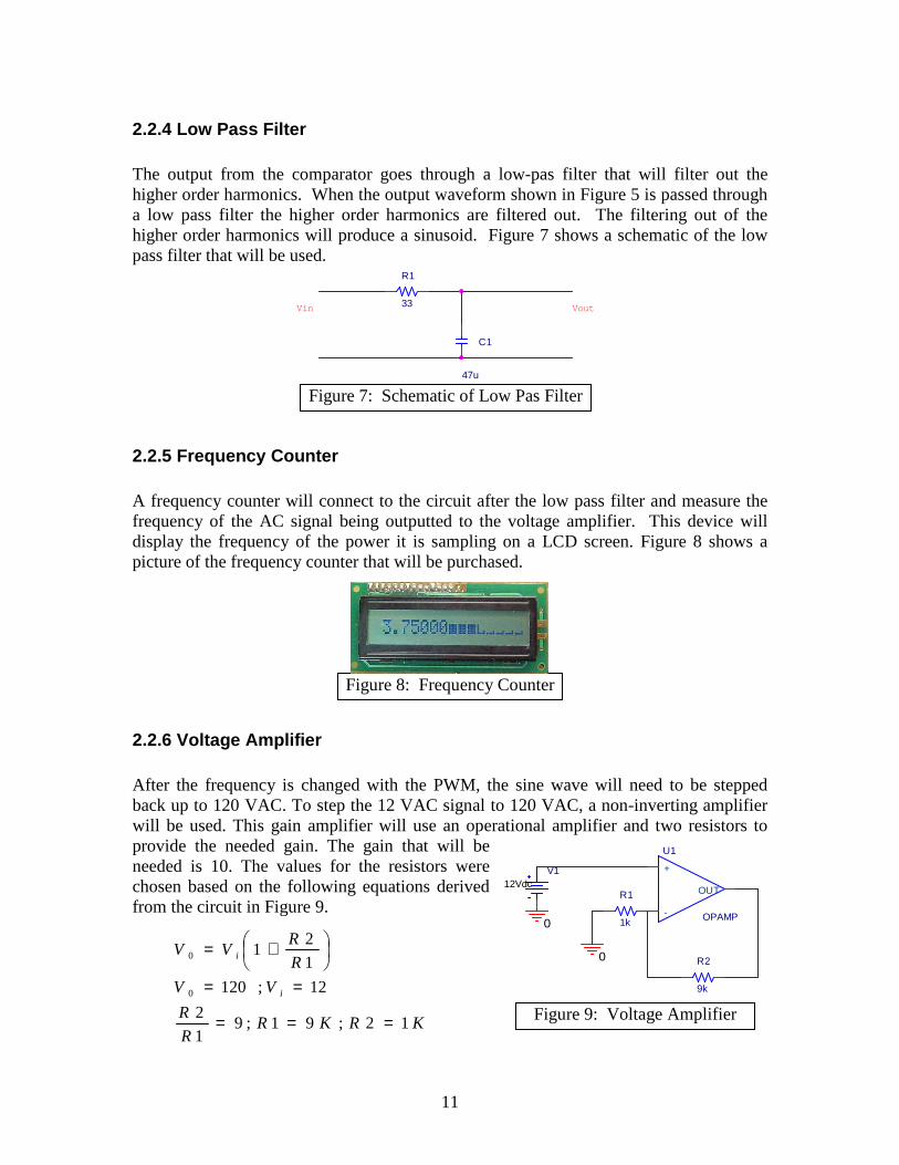
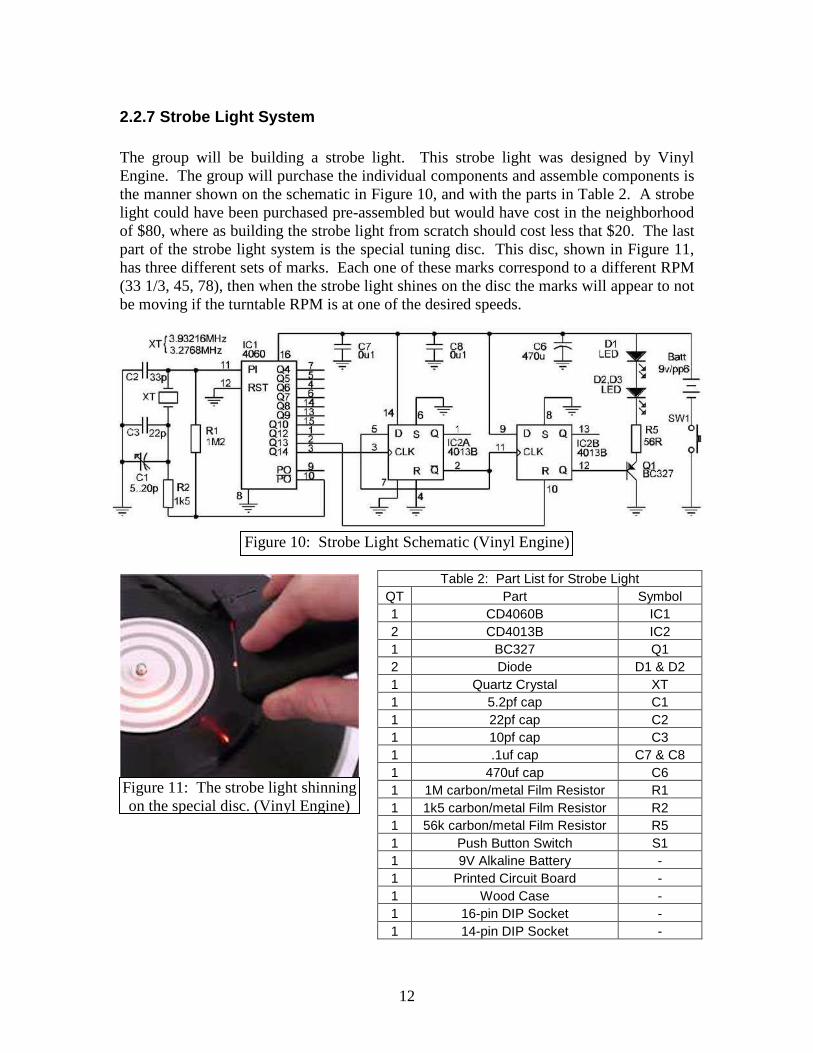
2.2.7 Strobe Light System The group will be building a strobe light. This strobe light was designed by Vinyl Engine. The group will purchase the individual components and assemble components is the manner shown on the schematic in Figure 10, and with the parts in Table 2. A strobe light could have been purchased pre-assembled but would have cost in the neighborhood of $80, where as building the strobe light from scratch should cost less that $20. The last part of the strobe light system is the special tuning disc. This disc, shown in Figure 11, has three different sets of marks. Each one of these marks correspond to a different RPM (33 1/3, 45, 78), then when the strobe light shines on the disc the marks will appear to not be moving if the turntable RPM is at one of the desired speeds.
Table 2: Part List for Strobe Light QT Part Symbol 1 CD4060B IC1 2 CD4013B IC2 1 BC327 Q1 2 Diode D1 & D2 1 Quartz Crystal XT 1 5.2pf cap C1 1 22pf cap C2 1 10pf cap C3 1 .1uf cap C7 & C8 1 470uf cap C6 1 1M carbon/metal Film Resistor R1 1 1k5 carbon/metal Film Resistor R2 1 56k carbon/metal Film Resistor R5 1 Push Button Switch S1 1 9V Alkaline Battery - 1 Printed Circuit Board - 1 Wood Case - 1 16-pin DIP Socket - 1 14-pin DIP Socket -
Figure 10: Strobe Light Schematic (Vinyl Engine)
Figure 11: The strobe light shinning on the special disc. (Vinyl Engine)
13
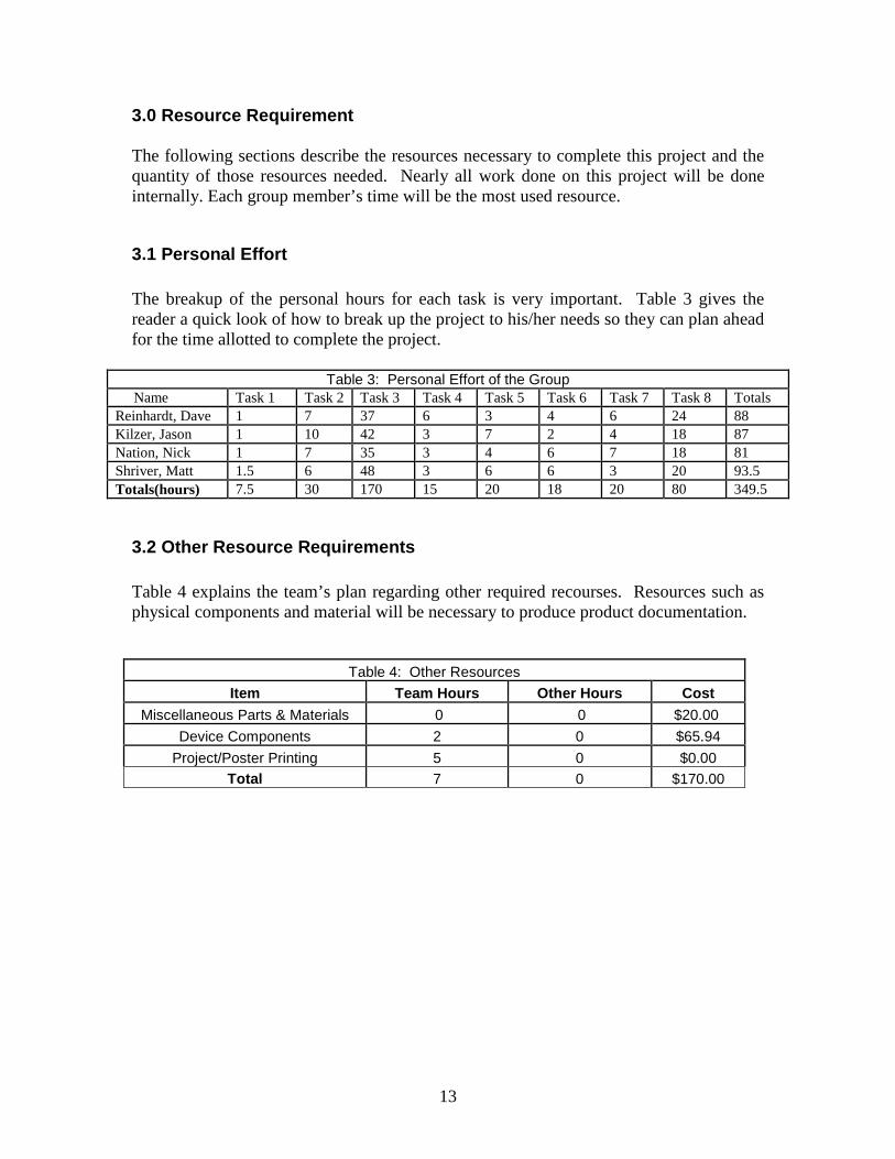
3.0 Resource Requirement The following sections describe the resources necessary to complete this project and the quantity of those resources needed. Nearly all work done on this project will be done internally. Each group member’s time will be the most used resource.
3.1 Personal Effort The breakup of the personal hours for each task is very important. Table 3 gives the reader a quick look of how to break up the project to his/her needs so they can plan ahead for the time allotted to complete the project.
Table 3: Personal Effort of the Group Name Task 1 Task 2 Task 3 Task 4 Task 5 Task 6 Task 7 Task 8 Totals Reinhardt, Dave 1 7 37 6 3 4 6 24 88 Kilzer, Jason 1 10 42 3 7 2 4 18 87 Nation, Nick 1 7 35 3 4 6 7 18 81 Shriver, Matt 1.5 6 48 3 6 6 3 20 93.5 Totals(hours) 7.5 30 170 15 20 18 20 80 349.5
3.2 Other Resource Requirements Table 4 explains the team’s plan regarding other required recourses. Resources such as physical components and material will be necessary to produce product documentation.
Table 4: Other Resources
Item Team Hours Other Hours Cost
Miscellaneous Parts & Materials 0 0 $20.00
Device Components 2 0 $65.94
Project/Poster Printing 5 0 $0.00 Total 7 0 $170.00
14
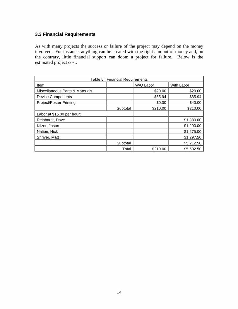
3.3 Financial Requirements As with many projects the success or failure of the project may depend on the money involved. For instance, anything can be created with the right amount of money and, on the contrary, little financial support can doom a project for failure. Below is the estimated project cost:
Table 5: Financial Requirements
Item W/O Labor With Labor
Miscellaneous Parts & Materials $20.00 $20.00
Device Components $65.94 $65.94
Project/Poster Printing $0.00 $40.00
Subtotal $210.00 $210.00
Labor at $15.00 per hour:
Reinhardt, Dave $1,380.00
Kilzer, Jason $1,290.00
Nation, Nick $1,275.00
Shriver, Matt $1,297.50
Subtotal $5,212.50
Total $210.00 $5,602.50

15
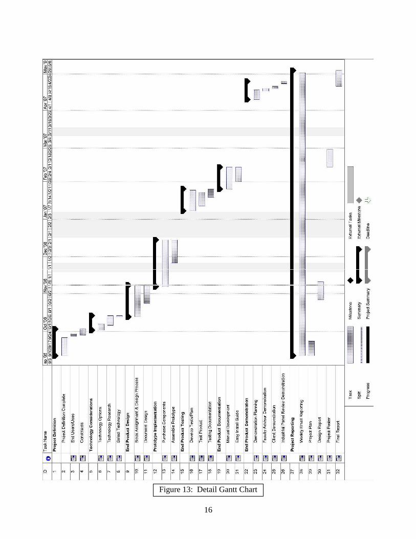
3.4 Schedules The group has stayed on the pace and the schedules presented in this document are the same as the ones presented in the group’s project plan. See Figure 12 for the detailed schedule of development of the precision variable frequency drive. See Figure 13 for the deadline schedule.
Figure 12: Deadlines Chart
16
Figure 13: Detail Gantt Chart

17
4.0 Closure Materials In closing, below is the contact information for all group members, advisor, and client. A closing summary is also included in this section.
4.1 Project Team Information This is the contact information for the precision variable frequency drive design group, clients and faculty advisor. Client Information: Name…………………………………………………………………………...Jim Walker Mailing Address…………………………………………………...112 North Dakota Ave. Ames, IA 50014 Telephone Number…………………………………………………………..515-231-1804 Email Address………………………………………………………[email protected] Faculty Advisor Information: Name……………………………………………………………..Ajjarapu Venkataramana Office………………………………………………………………………….1122 Coover Ames, IA 50011 Mailing Address…………………………………………………….2704 Valley View Rd. Ames, IA 50014 Office Telephone Number…………………………………………………...515-294-7687 Home Telephone Number…………………………………………………...515-292-3887 Fax…………………………………………………………………………...515-294-4263 Email Address.………………………………………………………[email protected] Student Team Information: Name………………………………………………………………………..…Jason Kilzer Major………………………………………………………………..Electrical Engineering Mailing Address……………………………………………………….…1302 Woodstock Ames, IA 50014 Telephone Number…………………………………………………………..515-451-7434 Email Address...…………………………………………………………[email protected] Name…………………………………………………………………………..Nick Nation Major ……………………………………………………………….Electrical Engineering Mailing Address……………………………………………………...309 Lynn Ave Apt. 4 Ames, IA 50014 Telephone Number……………………………………………………..……515-570-8281 Email Address………………………………………………………[email protected] Name……………………………………………………………………...David Reinhardt
18
Major………………………………………………………………..Electrical Engineering Mailing Address………………………………………………………...221 Sheldon Apt 4 Ames, IA 50014 Telephone Number…………………………………………………………..630-310-7218 Email Address.…………………………………………………………[email protected] Name…………………………………………………………………………..Matt Shriver Major………………………………………………………………..Electrical Engineering Mailing Address………………………………………………………….311 Maple Friant Ames, IA 50013 Telephone Number…………………………………………………………..402-639-2784 Email Address…………………………………………………...…[email protected]
4.2 Closing Summary The objective of the senior design project is to develop a precision variable frequency drive for an AC synchronous motor with a portable strobe light system for measuring rpm rate. The objective will be accomplished by making the precision variable frequency drive from an AC/DC converter, pulse width modulator, wave shaper and amplifier. The strobe light system will be a stand alone component made from a kit. These pieces will be developed and put together into a ready-to-manufacture prototype, enabling an audiophile to listen to their turntables with as much satisfaction as possible.

19
4.3 References Vinyl Engine. DIY Turntable Strobe. Retrieved on November 6, 2006 from
http://www.vinylengine.com/diy_strobe.shtml
20
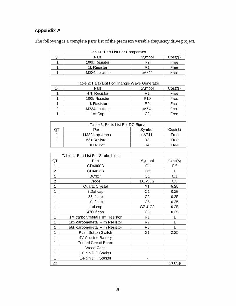
Appendix A The following is a complete parts list of the precision variable frequency drive project.
Table1: Part List For Comparator
QT Part Symbol Cost($) 1 100k Resistor R2 Free 1 1k Resistor R1 Free 1 LM324 op-amps uA741 Free
Table 2: Parts List For Triangle Wave Generator
QT Part Symbol Cost($) 1 47k Resistor R1 Free 1 100k Resistor R10 Free 1 1k Resistor R9 Free 2 LM324 op-amps uA741 Free 1 1nf Cap C3 Free
Table 3: Parts List For DC Signal
QT Part Symbol Cost($) 1 LM324 op-amps uA741 Free 1 68k Resistor R2 Free 1 100k Pot R4 Free
Table 4: Part List For Strobe Light
QT Part Symbol Cost($) 1 CD4060B IC1 0.5 2 CD4013B IC2 1 1 BC327 Q1 0.1 2 Diode D1 & D2 0.5 1 Quartz Crystal XT 5.25 1 5.2pf cap C1 0.25 1 22pf cap C2 0.25 1 10pf cap C3 0.25 1 .1uf cap C7 & C8 0.25 1 470uf cap C6 0.25 1 1M carbon/metal Film Resistor R1 1 1 1k5 carbon/metal Film Resistor R2 1 1 56k carbon/metal Film Resistor R5 1 1 Push Button Switch S1 2.25 1 9V Alkaline Battery - 1 Printed Circuit Board - 1 Wood Case - 1 16-pin DIP Socket - 1 14-pin DIP Socket - 22 13.85$
21
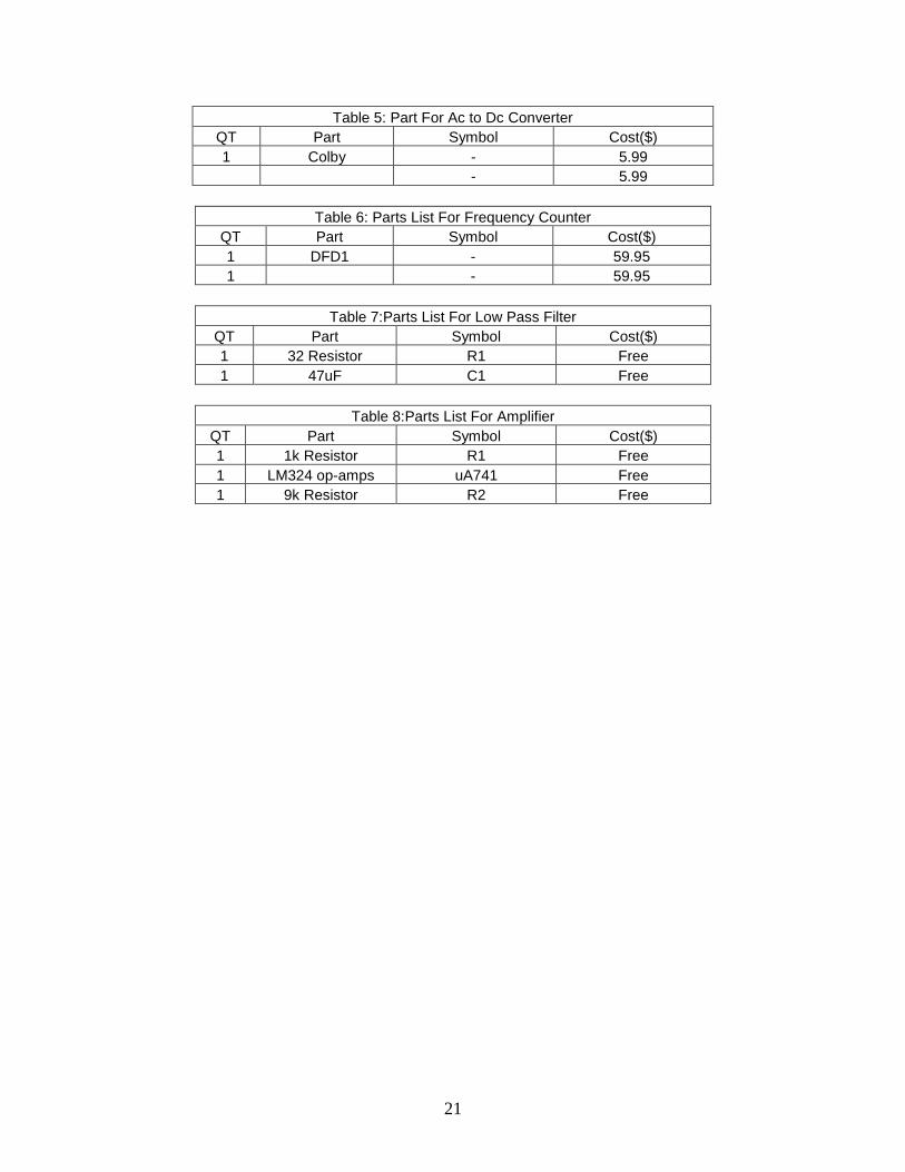
Table 5: Part For Ac to Dc Converter QT Part Symbol Cost($) 1 Colby - 5.99 - 5.99
Table 6: Parts List For Frequency Counter
QT Part Symbol Cost($) 1 DFD1 - 59.95 1 - 59.95
Table 7:Parts List For Low Pass Filter
QT Part Symbol Cost($) 1 32 Resistor R1 Free 1 47uF C1 Free
Table 8:Parts List For Amplifier
QT Part Symbol Cost($) 1 1k Resistor R1 Free 1 LM324 op-amps uA741 Free 1 9k Resistor R2 Free