Embed Size (px)
Citation preview

Research ArticlePredicting Response of Constructed Tunnel to AdjacentExcavation with Dewatering
Panpan Guo ,1 Feifei Liu,2 Gang Lei ,1,3 Xian Li ,2 Cheng-wei Zhu ,4 Yixian Wang ,2,5
Mengmeng Lu,6 Kang Cheng ,1,7 and Xiaonan Gong1
1Research Center of Coastal and Urban Geotechnical Engineering, Zhejiang University, Hangzhou 310058, China2School of Civil Engineering, Hefei University of Technology, Hefei 230009, China3Beijing Urban Construction Design & Development Group Company Limited, Beijing 100037, China4Institut für Geotechnik, Universität für Bodenkultur Wien, Feistmantelstrasse 4, 1180 Vienna, Austria5State Key Laboratory of Explosion Science and Technology, Beijing Institute of Technology, Beijing 100081, China6School of Mechanics and Civil Engineering, China University of Mining and Technology, Xuzhou 221116, China7China Railway 11th Bureau Group Co., Ltd., Wuhan 430061, China
Correspondence should be addressed to Gang Lei; [email protected] and Xian Li; [email protected]
Received 27 January 2021; Revised 25 February 2021; Accepted 2 March 2021; Published 18 March 2021
Academic Editor: Yu Wang
Copyright © 2021 Panpan Guo et al. This is an open access article distributed under the Creative Commons Attribution License,which permits unrestricted use, distribution, and reproduction in any medium, provided the original work is properly cited.
This paper proposes a new method for predicting the displacement and internal force of constructed tunnels induced by adjacentexcavation with dewatering. In this method, the total excavation-induced additional stress on the constructed tunnel is derived bysuperposing the additional stresses induced by excavation unloading and dewatering effects. The additional stress induced byunloading effect is calculated using Mindlin’s solution. The additional stress induced by dewatering effect is calculated using theprinciple of effective stress and the Dupuit precipitation funnel curve. With the beam on elastic foundation method, the totaladditional stress is then used for calculating the tunnel displacement and internal force caused by adjacent excavation withdewatering. Based on three well-documented case histories, the performance of the proposed method is verified. Moreover, aparametric analysis is also performed to capture the effects of excavation depth, tunnel-to-excavation distance, initial water level,excavation plan view size, and specific yield on the responses of the constructed tunnels. The results indicate that the effect ofexcavation depth on the tunnel maximum vertical displacement, maximum bending moment, and maximum shear force ismore significant at an excavation depth greater than the cover depth of the constructed tunnel. The tunnel maximum verticaldisplacement, maximum bending moment, and maximum shear force decrease nonlinearly with an increase in the tunnel-to-excavation distance and the initial water level. Among the investigated parameters, the excavation dimension in the tunnellongitudinal direction affects most the tunnel responses. The effect of specific yield on the tunnel displacement and internalforce induced by adjacent excavation with dewatering becomes more obvious as increasing the initial water level and excavationdepth.
1. Introduction
The rapid development of urban rail traffic provides conve-nience of getting around for people. The development advan-tage along an urban rail traffic line has been stimulating theconstruction of high-rise buildings adjacent to the urban railtraffic line. Therefore, it is not rare to find an excavation thatis adjacent to preexisting subway tunnels, piles, pipelines, orother shallowly buried facilities [1–5]. Inevitably, the adja-
cent excavation has an adverse effect on the constructedstructures or facilities, and many studies have focused on thisissue in recent decades [6–8]. It has been found that theexcavation-induced redistribution of ground stress can leadto the generation of additional stress and deformation inthe tunnel structure. If the induced tunnel deformation isexcessive, the safe operation of the subway or other facilitieswill be affected [9–12]. As a result, an investigation into theexcavation-induced internal force and deformation
HindawiGeofluidsVolume 2021, Article ID 5548817, 17 pageshttps://doi.org/10.1155/2021/5548817

characteristics of a constructed subway tunnel has great sig-nificance to the safe operation of the subway tunnel [13–15].
Many analysis methods for excavation-induced internalforce and deformation in a subway tunnel have been pro-posed, which can be classified into the numerical analysismethod [16–19], field monitoring method [20–23], and the-oretical analysis method [24–26]. The numerical analysismethod can simulate the complex process of excavationand is therefore a favored choice for engineers andresearchers. However, this method suffers from several dis-advantages such as cumbersome modelling, time-consuming computation, large discrepancy between thecomputed results using different numerical analysis software,and low reliability of the computed results. The field moni-toring method can directly obtain the excavation-induceddeformation behavior of the constructed tunnel during thewhole excavation phase. However, this method is susceptibleto the workers’ operating skill and the quality of monitoringequipment. Moreover, the field monitoring method corre-sponds to only a specific engineering project and does notinvolve a discussion of the deformational mechanism andtherefore has a limited guiding significance for the excava-tions in other areas.
The theoretical analysis method for excavation-inducedinternal force and deformation characteristics in a subwaytunnel has been extensively investigated by many scholars.At the present time, the most common-adopted theoreticalanalysis method is the two-stage method [27, 28]. Thismethod divides the considered problem into two separatestages: the excavation unloading stage and the tunnelresponding stage. Depending on the concept of predictingthe excavation-induced response of the constructed tunnel,the method for calculating the excavation-induced internalforce in the constructed tunnel can be categorized into theadditional load method and the additional displacementmethod [29–31]. The additional load method is performedin two steps. First, apply the excavation-induced additionalstress in the tunnel position calculated by Mindlin’s solutionto the constructed subway tunnel. Second, calculate the inter-nal force and deformation in the constructed tunnel underthe effect of the applied excavation-induced additional stress,by adopting the beam on elastic foundation theory [32, 33].The additional displacement method is also performed intwo steps. First, calculate the excavation-induced ground dis-placement in the tunnel position by using Peck’s formula[34]. Second, impose the calculated displacement in the firststep on the constructed tunnel to predict the internal forceand deformation in the constructed tunnel [35, 36].
The change of the initial stress field in the groundinduced by an excavation is a rather complex phenomenon.This phenomenon is associated with not only the excavationunloading effect but also the excavation dewatering effect.Previous research has indicated that excavation dewateringaffects significantly the internal force and deformation char-acteristics of the constructed facilities adjacent to the excava-tion [37–40]. Based on the effective stress principle, Ou et al.[41] proposed an analytical method for predicting the influ-ence of excavation with dewatering on the response of theconstructed tunnel underlying the excavation. This method
takes account of the excavation dewatering effect but is notapplicable to the condition where the excavation is adjacentlaterally to the constructed tunnel. In addition, based onDarcy’s law and the Dupuit approximation, Anderson [42]derived a formula describing the steady flow of groundwaterand determined the precipitation funnel curve using thegroundwater surfaces on the external and internalboundaries.
In this paper, the excavation unloading effect and theexcavation dewatering effect are modelled separately. Mind-lin’s solution is used to calculate the additional stress in theconstructed tunnel induced by the excavation unloadingeffect. Based on the Dupuit precipitation funnel curve, theeffective stress in the constructed tunnel induced by the exca-vation dewatering effect is obtained. The additional stressand the effective stress obtained above are then superimposedto derive the total additional stress in the constructed tunnel.After this, the additional load method is adopted to predictthe internal force and displacement characteristics for theconstructed tunnel adjacent to an excavation with dewater-ing. The innovation of this study lies in that the calculationof the excavation-induced additional stress takes account ofnot only the excavation unloading and dewatering effectsbut also the entire region subjected to the influence of dewa-tering by introducing the Dupuit precipitation funnel curve.
2. Total Additional Stress Induced byExcavation with Dewatering
In calculating the additional stress in the constructed tunnelinduced by excavation with dewatering, the time effectinvolved in the excavation and dewatering process is nottaken into account, and only the initial state and the finalstate of the excavation with dewatering have been considered.In general, the additional stress in the constructed tunnelinduced by excavation with dewatering is composed of twoparts: one is the effective stress effect induced by dewatering,and the other is the unloading effect induced by excavation.
2.1. Additional Stress Induced by Dewatering. It is assumedthat the phreatic line induced by dewatering conforms tothe Dupuit approximation [42]. In detail, the assumptionsare as follows: (1) the aquifer is homogeneous, isotropic, iso-pachous, and horizontal; (2) the flow of the groundwater islaminar and stable and conforms to Darcy’s law; (3) the staticwater level is horizontal; and (4) the contour of recharge ofthe pumping well is of fixed water level and is cylindrical inshape. A schematic of the dewatering during an excavationis presented in Figure 1.
The adopted water level lowing curve has the form
y2 = h′2 + H2 − h′2� � ln x − ln r
ln R − ln r, ð1Þ
where y = elevation of the phreatic line after dewatering (m),h′ = distance between the water level of the dewatering welland the impermeable layer (m), H = elevation of the initialwater level (m), r = radius of the dewatering well (m), R =radius of influence of dewatering (m), x = horizontal
2 Geofluids

distance to the axis of the dewatering well (m), and H ′ =distance between tunnel axis and impermeable layer.
The radius of influence of dewatering can be calculatedusing an empirical equation
R = 2sffiffiffiffiffiffiffiffiHK
p, ð2Þ
where s = dewatering depth of the dewatering well (m) andK = permeability coefficient of the ground (m/d).
The change of the water level above the constructed tunnelcan thus be estimated using Equations (1) and (2). The verticaladditional stress applied on the constructed tunnel is calcu-lated using the effective stress principle. Before dewatering,the constructed tunnel is subjected to earth pressure and porewater pressure, and the effective stress is calculated by
σ = h0γ0 + H − yð Þ γsat − γwð Þ, ð3Þ
where h0 = distance between ground surface and initial waterlevel (m), γ0 = dry unit weight of soil (kN/m3), γsat =saturated unit weight (kN/m3), and γw = unit weight of water(kN/m3).
After dewatering, the effective stress applied to the con-structed tunnel is given by
σ′ = h0γ0 + H − yð Þ γsat − 1 − μð Þγwð Þ, ð4Þ
where μ = specific yield. The magnitude of μ is associatedwith soil properties including the mineral composition, par-ticle size, grain grading, degree of sorting, and void ratio.The mineral composition affects the specific yield by theadsorption force on the hydrone. A summary of the empiri-cal values of the specific yield for various types of soils is pre-sented in Table 1.
The dewatering-induced change of the vertical effectivestress applied on the constructed tunnel is calculated by
σvw = σ′ − σ = μ H − yð Þγw = μhγw: ð5Þ
2.2. Additional Stress Induced by Unloading. The calculationof the additional stress in the constructed tunnel inducedby excavation unloading effect is generally based on Mind-
lin’s solution [43]. A schematic of the calculation model forthe additional stress induced by unloading is presented inFigure 2. The assumptions involved in Mindlin’s solutionare as follows: (1) the ground is a homogeneous, elastichalf-space, (2) the time and space effects involved in the exca-vation are overlooked, and (3) the influence of the con-structed tunnel on the excavation unloading stress is nottaken into account.
According to Mindlin’s solution, under the effect of unitforce σdξdη applied at the point ðξ, ηÞ at the excavation bot-tom, the vertical and horizontal additional stresses at thepoint (x, y, z) on the tunnel axis are calculated by
σvd = −γd
8π 1 − νð Þ1 − 2νð Þ z − dð Þ
R31
−� 1 − 2νð Þ z − dð Þ
R32
+ 3 z − dð Þ3R51
+ 3 3 − 4νð Þz z + dð Þ2 − 3d z + dð Þ 5z − dð ÞR52
+ 30zd z + dð Þ3R72
#,
ð6Þ
σhd = −
γd8π 1 − vð Þ −
1 − 2νð Þ z − dð ÞR31
�+ 3 x − ξð Þ2 z − dð Þ
R51
−1 − 2νð Þ 3 z − dð Þ − 4v z + dð Þ½ �
R32
+3 3 − 4νð Þ x − ξð Þ2 z − dð Þ − 6d z + dð Þ 1 − 2νð Þz − 2νd½ �n o
R52
+ 4 1 − νð Þ 1 − 2νð ÞR2 R2 + z + dð Þ 1 − x − ξð Þ2
R2 R2 + z + dð Þ −x − ξð ÞR22
" #
+ 30 x − ξð Þ2zd z + dð ÞR72
#,
ð7Þ
Impermeable layer
Tunnel
Dewateringwell
Excavation
Excavationbottom
Ground surface
Initial groundwater level
Groundwater level dueto dewatering
y
R
H
ho
h
H′
h′
X
Figure 1: Schematic of dewatering during excavation.
Table 1: Empirical values of the specific yield for various types ofsoils.
Soil type Specific yield
Clay 0.02–0.035
Loam 0.03–0.045
Sandy loam 0.035–0.06
Loess-like loam 0.02–0.05
Loess-like sandy loam 0.03–0.06
Silty sand 0.06–0.08
Silty fine sand 0.07–0.01
Fine sand 0.08–0.11
Medium-fine sand 0.085–0.12
Medium sand 0.09–0.13
Medium-coarse sand 0.10–0.15
Coarse sand 0.11–0.15
Clay cemented sandstone 0.02–0.03
Fractured limestone 0.008–0.10
3Geofluids

R1 =ffiffiffiffiffiffiffiffiffiffiffiffiffiffiffiffiffiffiffiffiffiffiffiffiffiffiffiffiffiffiffiffiffiffiffiffiffiffiffiffiffiffiffiffiffiffiffiffiffiffiffiffiffiffix − ξð Þ2 + y − ηð Þ2 + z − dð Þ2
q, ð8aÞ
R2 =ffiffiffiffiffiffiffiffiffiffiffiffiffiffiffiffiffiffiffiffiffiffiffiffiffiffiffiffiffiffiffiffiffiffiffiffiffiffiffiffiffiffiffiffiffiffiffiffiffiffiffiffiffiffix − ξð Þ2 + y − ηð Þ2 + z + dð Þ2
q: ð8bÞ
Similarly, under the effect of a unit force K0γτdηdτapplied at the point ðη, τÞ on the vertical side of the excava-tion, the vertical and horizontal additional stresses at thepoint (x, y, z) on the tunnel axis are calculated by
σvc = −K0γτS
8π 1 − νð Þ− 1 − 2νð Þ
R33
�+ 3 z − τð Þ2
R53
+ 1 − 2νð ÞR34
+ 3 3 − 4νð Þ z + τð Þ2R54
+ −6τR54
τ + 1 − 2νð Þ z + τð Þ + 5z z + τð Þ2R24
!#,
ð9Þ
σhc = −Κ0γτS
8π 1 − νð Þ1 − 2νð ÞR33
�+ 3S2
R53+ 1 − 2νð Þ 5 − 4vð Þ
R34
+ 3 3 − 4νð ÞS2R54
+ 4 1 − νð Þ 1 − 2νð ÞR4 R4 + z + τð Þ2 3 − S2 3R4 + z + τð Þ
R24 R4 + z + τð Þ
� �
−6τR54
3τ − 3 − 2νð Þ z + τð Þ + 5xS2R24
� ��,
ð10Þ
R3 =ffiffiffiffiffiffiffiffiffiffiffiffiffiffiffiffiffiffiffiffiffiffiffiffiffiffiffiffiffiffiffiffiffiffiffiffiffiffiffiffiffiffiffiffiffiffiffiffiffiffiffiffiffiffix − ξð Þ2 + y − ηð Þ2 + z − τð Þ2
q, ð11aÞ
R4 =ffiffiffiffiffiffiffiffiffiffiffiffiffiffiffiffiffiffiffiffiffiffiffiffiffiffiffiffiffiffiffiffiffiffiffiffiffiffiffiffiffiffiffiffiffiffiffiffiffiffiffiffiffiffix − ξð Þ2 + y − ηð Þ2 + z + τð Þ2
q, ð11bÞ
where γ = unit weight of soil (kN/m3), d = excavation depth(m), ν = Poisson’s ratio, K0 = coefficient of lateral earthpressure at rest (K0 = 1 − sin φ, where φ is the angle ofinternal friction of soil), S = distance between the vertical sideof the excavation and the axis of the constructed tunnel (m),and τ = depth of the calculation point on the vertical side ofthe excavation (m).
By integrating Equations (6) and (7) over the excavationbottom and integrating Equations (9) and (10) over the ver-tical side of the excavation, the excavation unloading-induced additional stress corresponding to the excavationbottom and to the vertical side of the excavation can bederived, respectively. In this case, the total vertical and hori-zontal additional stresses in the constructed tunnel inducedby excavation with dewatering, σv and σh, have the forms
σv = σvw + σv
d + σvc , ð12aÞ
σh = σhd + σhc : ð12bÞ
3. Response of Constructed Tunnel
The internal force and displacement characteristics for theconstructed tunnel under the effect of the additional stressinduced by the adjacent excavation with dewatering are pre-dicted in this section based on the beam on elastic foundationtheory. To achieve this, it is assumed that (1) the constructedtunnel is equivalent to a long beam on an elastic foundation,(2) the contact between the constructed tunnel and theground is perfect, and (3) compatibility of deformation is sat-isfied. A schematic of the calculation model for the responseof the constructed tunnel under the additional stress is pre-sented in Figure 3.
According to the Winkler foundation beam model, theequation of deflection curve for the constructed tunnel underthe effect of the additional stress has the form
EIeqd4w xð Þdx4
+Dkw xð Þ = p xð Þ, ð13Þ
where EIeq = equivalent longitudinal stiffness of the con-structed tunnel (kN·m2), wðxÞ = displacement of the con-structed tunnel (m), D = external diameter of the constructedtunnel (m), k = coefficient of subgrade reaction (kN·m3), andpðxÞ = additional stress applied on the constructed tunnel(kPa).
In Equation (13), pðxÞ and EIeq are given by
p xð Þ = σD, ð14aÞ
EIeq = ηEI, ð14bÞwhere η = reduction coefficient and EI = actual longitudinalstiffness of the constructed tunnel (kN·m2).
The magnitude of the reduction coefficient η varies,depending on many factors such as the form of tunnel cir-cumferential seam, bolt quantity, and tunnel lining thickness[44–46]. By performing a series of experiments, Xu [47]investigated the magnitude of the reduction coefficient η atvarious forms of tunnel circumferential seam. It was foundthat the magnitudes of the reduction coefficient η are, respec-tively, 0.145, 0.13, and 0.114 at homogeneous, staggered, andcontinuous forms of the tunnel circumferential seam.
A previous experimental study has indicated that thecoefficient of subgrade reaction k is related to not only thesoil strength but also the stiffness of the foundation beam
Excavation
Groundsurface
y
z
x
Unloading direction
L
D
B
d
Tunnel
Figure 2: Schematic of the calculation model for additional stressinduced by excavation unloading.
4 Geofluids

[48, 49]. Therefore, the empirical equation proposed by Vesic[50] and Attewell et al. [51] was adopted to estimate the coef-ficient of subgrade reaction k:
k = 2kVesic =1:3Es
D 1 − ν2ð Þ
ffiffiffiffiffiffiffiffiffiffiEsD
4
EIeq
12
s, ð15Þ
where Es = elasticmodulus of the ground (MPa).As Equation (13) is an inhomogeneous differential equa-
tion of fourth order with a constant coefficient, it is extremelydifficult to derive directly its analytical solution. Therefore,the form of the analytical solution was assumed to becomposed of two parts: the general solution part and theparticular solution part. Let pðxÞ = 0, one can obtain the cor-responding homogeneous differential equation
EIeqd4w xð Þdx4
+Dkw xð Þ = 0: ð16Þ
Therefore, the general solution has the form
w xð Þ = eλx C1 cos λxð Þ + C2 sin λxð Þð Þ+ e−λx C3 cos λxð Þ + C4 sin λxð Þð Þ,
ð17aÞ
λ =ffiffiffiffiffiffiffiffiffiffiffiDK4EIeq
4
s, ð17bÞ
where C1, C2, C3, andC4 = undetermined coefficients and λ= elastic characteristic coefficient.
Considering the symmetry of the beam on an elasticfoundation, we have
w xð Þjx→∞ = 0, ð18aÞ
dw xð Þdx
x→∞
= 0: ð18bÞ
By manipulation of Equations (17) and (18), one obtainsC1 = C2 = 0 and C3 = C4. Let C3 = C4 = C, the form of thegeneral solution for Equation (16) can be transformed to
w xð Þ = Ce−λx cos λxð Þ + sin λxð Þð Þ: ð19Þ
Assume that a point load P0 is applied at the central sec-tion of the beam on an elastic foundation. Considering theequilibrium between the subgrade reaction and the externalload, we have
2DkCð∞0e−λx cos λxð Þ + sin λxð Þð Þdx = P0: ð20Þ
Manipulation of Equation (20) leads to
C = P0λ
2Dk : ð21Þ
Substituting Equation (21) into Equation (19), the formof the general solution becomes
w xð Þ = P0λ
2Dk e−λx cos λxð Þ + sin λxð Þð Þ: ð22Þ
For a tunnel subjected to an additional distributed loadqðxÞ, the point load at the point ξ on the tunnel is qðξÞdξ.Under this point load, the induced displacement at the pointx on the tunnel, dwðxÞ, is calculated, according to Equation(22), as
dw xð Þ = P ξð Þλ2Dk e−λ x−ξj j cos λ x − ξj jð Þ + sin λ x − ξj jð Þð Þdξ:
ð23Þ
Integrating Equation (23) over the range of the distribu-tion of the additional distributed load, the solution forEquation (13) is derived:
w xð Þ = λ
2Dk
ð+∞−∞
P ξð Þe−λ x−ξj j cos λ x − ξj jð Þ + sin λ x − ξj jð Þð Þdξ:
ð24Þ
Consequently, the bending moment and shear force atthe point x on the tunnel axis are calculated, respectively,by
M = −EIeqd2w xð Þdx2
, ð25Þ
Q = dMdx
= −EIeqd3w xð Þdx3
: ð26Þ
The proposed method for predicting the response of aconstructed tunnel to an adjacent excavation with dewater-ing treats the constructed tunnel as a long beam on an elas-tic foundation and calculates the internal force anddeformation for the constructed tunnel by using the Wink-ler foundation model. The required parameters for the pro-posed method include the equivalent longitudinal stiffnessof the constructed tunnel EIeq, external diameter of theconstructed tunnel D, and coefficient of subgrade reactionk. The advantages of the proposed method over othermodels are lesser parameters and convenient calculationprocess.
Tunnelk
D
P (X)
Figure 3: Schematic of calculation model for tunnel response underthe additional stress.
5Geofluids

4. Verification
The performance of the proposed theoretical method for pre-dicting the deformation and internal force characteristics of aconstructed tunnel induced by an adjacent excavation withdewatering is challenged against three well-documented casehistories. The predicted tunnel displacement characteristicsare verified by the comparisons with the monitoring dataobtained in the field and the three-dimensional finite elementanalysis results obtained in this study. The ability of the pro-posed method in well predicting the tunnel internal forcecharacteristics is demonstrated by comparing it with thethree-dimensional finite element analysis results.
4.1. Shanghai Dongfang Road Interchange Project. The firstcase history used for verifying the proposed method is theShanghai Dongfang Road Interchange (SDRI) Projectreported in Xu and Huang [52]. In this case history, the planview showing the relative position of the excavation and thetunnels is presented in Figure 4. The soil parameters for thiscase history are listed in Table 2. The geometry of the excava-tion resembles a parallelogram of 26m in length and 18m inwidth. The short side of the excavation is oriented at 66° rel-ative to the x-axis of the coordinate system. The excavationdepth is approximately 6.5m. The angle between the axis ofthe constructed tunnels and the y-axis of the coordinate sys-tem is 45°. The upline of the constructed tunnels is directlybelow the excavation. The minimum distance between thetunnel crown and the excavation bottom is 2.76m, with thetunnel cover depth being approximately 9.26m. The externaldiameter and the equivalent stiffness of the constructed tun-nels are, respectively, 6.2m and 3:93 × 107 kN·m2. In theoret-ical calculation, it was assumed that the upline of theconstructed tunnels was parallel with the excavation, consid-ering the relatively small angle between the upline and theexcavation.
In theoretical calculation for this case history, the hori-zontal additional stress in the upline of the constructed tun-nels induced by excavation can be neglected because of therelative position of the upline and the excavation. In otherwords, the predicted tunnel deformation using the proposedmethod takes account of only the vertical additional stressinduced by excavation.
Figure 5 presents the excavation-induced vertical dis-placements of the upline tunnel for the SDRI Projectobtained by finite element analysis, field measurement, andtheoretical calculation. The finite element analysis resultspresented in Figure 5 were obtained by Xu and Huang [52]using the MARC software. From Figure 5, it can be indicatedthat the distribution of the tunnel vertical displacement alongthe tunnel axis is similar for different methods. The distribu-tion conforms approximately to a Gaussian distribution. Thetunnel vertical displacements reach maxima in the middle ofthe upline tunnel axis intersecting with the vertical projectionof the excavation. The maximum tunnel vertical displace-ments are, respectively, 11.5, 16, and 16.96mm correspond-ing to the finite element analysis, field measurement, andtheoretical calculation. The maximum tunnel vertical dis-placement calculated by the proposed method is more agree-
able to the field measurement when compared with the finiteelement analysis result. Moreover, the predicted tunnel verti-cal displacements by the proposed theoretical method aregenerally greater than that by finite element analysis and field
28 m
Excavation
24 my
x
Up-line tunnelDown-line tunnel
18.1
m
Figure 4: Site plan view for the SDRI Project.
Table 2: Soil parameters for the SDRI Project [52].
Soil layer h (m) γ (kN/m3) c (kPa) μ ES (MPa)
Artificial fill 1.82 18.5 16 NA NA
Silty clay ②1 1.13 18.4 10 0.4 6.43
Silty clay ②2 0.82 17.7 13 0.3 3.71
Silty clay ③1 1.08 17.7 14 0.3 4.43
Sandy silt ③2 2.28 18.3 3 0.35 9.72
Silty clay ③3 2.46 17.2 13 0.35 3.63
Sandy silt 8.7 16.6 14 0.35 2.27
Clay ⑤1 2.41 17.9 19 0.4 4.07
Silty clay ⑤2 3.89 18.1 18 0.4 4.55
Silty clay 4.25 19.4 43 0.35 6.09
Note. h = soil thickness; γ = unit weight; c = cohesion; μ = Poisson’s ratio; ES=modulus of compressibility; NA = not available.
–75 –60 –45 –30 –15 0 15 30 45 60 75
y (m)
Ver
tical
disp
lace
men
t (m
m)
4
–4
0
8
12
16
20
24
Numerical calculation by Xu and Huang (2008)Field measurement by Xu and Huang (2008)Theoretical calculation by the proposed method
Figure 5: Excavation-induced tunnel vertical displacements for theSDRI Project.
6 Geofluids

Hengfeng bank office building
Down-line tunnel
Up-line tunnel
Monitoring points
30 29 28 27 26 25 24 23 22 21 20 19 18 17 16 15 14 13 12 11 10 9 8 7 6 5 4 3 2 1
N
(a)
2.0
m5.
1 m
3.8
mLattice column
Bottom plate
Supporting
Supporting
Upright pile
Diaphragm wall
Up-line tunnelDown-line tunnel
6.2 m
Pile
13 m
10.3–10.9 m
9.0–
10.7
m
9.0–
10.7
m
(b)
Figure 6: Schematic of the relative position of the excavation and the tunnel for the HBOB Project: (a) plan view and (b) cross-section view.
Table 3: Soil parameters for the HBOB Project [53].
Soil layer h (m)γ
(kN/m3)c
(kPa)ES
(MPa)φ
(degree)
Plain fill ① 2.0–4.5 18.9 15 NA 10
Powder stickyclay ②
2.5–4.8 19.6 32.35 6.01 13.74
Silt ③ 1.2–4.3 18.8 9.84 10.76 27.83
Silty clay ④1 2.1–5.6 18.9 17.46 6.54 13.91
Silty clay ④2 1.8–3.8 18.7 10.86 7.6 20.29
Silty clay ④3 5.8–7.0 18.9 20.58 5.18 12.26
Clay ⑤ 3.1–4.1 20.1 60.78 7.67 13.81
Silty clay ⑥ 6.0–7.2 19.1 34.59 7.53 16.65
Silty clay ⑦ 2.0–3.5 18.8 20.4 6.47 13.19
Silty clay ⑧ 8.8–9.9 18.7 15.36 6.97 20.24
Silty clay ⑨ 5.0–6.9 19.5 27.34 6.85 12.53
Silty clay ⑩11.5–12.1
19.4 23.22 7.31 14.07
Note. h = soil thickness; γ = unit weight; c = cohesion; ES =modulus ofcompressibility; φ = internal friction angle; NA = not available. Poisson’sratio was taken as 0.35 in the calculation for all the soil layers.
Monitoring points
32 28 24 20 16 12 8 4 0–5
0
5
10
Hor
izon
tal d
ispla
cem
ent (
mm
)
Theoretical calculation by the proposed methodField measurement by sun (2017)
Figure 7: Excavation-induced tunnel horizontal displacements forthe HBOB Project.
7Geofluids

measurement. For this, the primary reason is that the pro-posed theoretical method has not taken account of the influ-ence of excavation supporting on the excavation unloading-induced additional stress.
4.2. Hengfeng Bank Office Building Project. The second casehistory used for verifying the proposed method is the Heng-feng Bank Office Building (HBOB) Project reported by Sun[53]. In this case history, an excavation adjacent to theSuzhou Metro Line 1 was made for the construction of anoffice building for Hengfeng Bank. The excavation geometryis approximately a rectangle with its length and width being,respectively, 85m and 45m. The average excavation depth is10.6m. To ensure stability and safety, diaphragm walls andconcrete structs were used to support the excavation. The rel-ative position of the excavation and the tunnel is depicted inFigure 6. Table 3 summarizes the soil parameters for theHBOB Project.
From Figure 6, it can be seen that the tunnel axis isapproximately parallel with the south side of the excavation.The distance between the excavation side and the tunnelperiphery ranges from 10.3m to 10.9m. The cover depth ofthe tunnel ranges from 9.0m to 10.7m. The minimum dis-tance between the upline and downline tunnels is 6.8m.The external and internal diameters and the equivalent stiff-ness are, respectively, 6.2m, 5.5m, and 3:45 × 107 kN·m2.Monitoring was performed at 30 cross-sections of the uplineand downline tunnels with the interval being 5 ring-lengths.For convenience, in theoretical calculation, it was assumedthat the tunnels are parallel with the excavation and thatthe excavation is rectangular in shape.
A comparison of the excavation-induced horizontal dis-placements of the upline tunnel for the HBOB Projectbetween the theoretical calculation and field measurementis made in Figure 7. It can be noted that a slight discrepancyexists between the theoretical calculation and field measure-ment. The maximum tunnel horizontal displacement occursat a position corresponding to the middle of the excavation,both for the theoretical calculation and field measurement.The maximum tunnel horizontal displacements predictedby the proposed method and monitored by instrumentationsare, respectively, 6mm and 5.2mm. The overestimate of themaximum tunnel horizontal displacement by the proposedmethod is attributed to the overlook of the influence of exca-vation supporting and stratigraphic distribution.
4.3. Hefei Metro Line 1 Yungu Road Station Project. The thirdcase history used for verifying the proposed method is theHefei Metro Line 1 Yungu Road Station (HMLYRS) Project.An imaginary excavation is made adjacent to the HMLYRSProject. By performing three-dimensional finite elementanalysis, the excavation-induced tunnel internal force anddeformation characteristics are compared between the theo-retical calculation and numerical analysis results.
According to the drilling data in terms of age of deposi-tion and genetic type as well as the laboratory testing results,the ground stratums for the HMLYRS Project are composedof six layers: miscellaneous fill, clayey soil I, clayey soil II,clayey soil III, highly weathered sandstone, and moderatelyweathered sandstone. The parameters for these soil layersare summarized in Table 4. The miscellaneous fill consistsof construction waste, natural fibers [54–58], and other mate-rials. The groundwater level is about 2.5m below the groundsurface. The specific yield was taken as 0.1 in the theoreticalcalculation.
In the three-dimensional finite element analysis, the planview size of the excavation was assumed to be 40m × 20m× 10m. The water level within the excavation after dewater-ing was assumed to be 0.5m below the excavation bottom.The cover depth of the axis of the constructed tunnels forthe HMLYRS Project is 20m. The distance between the exca-vation boundary and the tunnel axis is 10m. The externaland internal diameters of the constructed tunnels are, respec-tively, 6.2m and 5.4m. Taking no account of the influence ofthe segment joint strength, the equivalent stiffness of the con-structed tunnels was taken as 3:45 × 107 kN·m2. In order toensure that the numerical analysis results are consistent with
Table 4: Soil parameters for the HMLYRS Project.
Soil layer h (m) γ (KN/m3) c (kPa) μ ES (MPa) φ (degree) k (m/d)
Miscellaneous soil 5.1 17.5 8 0.35 NA 10 0.001
Clay1 4.7 19.8 10 0.3 40 13 0.0006
Clay2 6.4 20.2 15 0.29 30 13 0.0004
Clay3 6.5 20.5 25 0.26 30 14 0.0004
SWS 1.1 21 30 0.26 70 20 NA
Weathered sandstone NA 22 40 0.24 90 25 NA
Note. h = soil thickness; γ = unit weight; c = cohesion; μ = Poisson’s ratio; ES =modulus of compressibility; φ = internal friction angle; k = permeabilitycoefficient; NA = not available; SWS = strongly weatherly sandstone.
Excavation
Tunnel140 m
40 m
120 m
40 m
20 m
Figure 8: Meshing of numerical model for the HMLYRS Project.
8 Geofluids
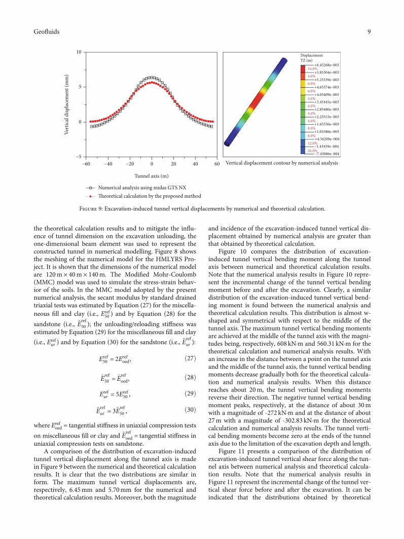
the theoretical calculation results and to mitigate the influ-ence of tunnel dimension on the excavation unloading, theone-dimensional beam element was used to represent theconstructed tunnel in numerical modelling. Figure 8 showsthe meshing of the numerical model for the HMLYRS Pro-ject. It is shown that the dimensions of the numerical modelare 120m × 40m × 140m. The Modified Mohr-Coulomb(MMC) model was used to simulate the stress-strain behav-ior of the soils. In the MMC model adopted by the presentnumerical analysis, the secant modulus by standard drainedtriaxial tests was estimated by Equation (27) for the miscella-neous fill and clay (i.e., Eref
50 ) and by Equation (28) for the
sandstone (i.e., ~Eref50 ); the unloading/reloading stiffness was
estimated by Equation (29) for the miscellaneous fill and clay
(i.e., Erefur ) and by Equation (30) for the sandstone (i.e., ~E
refur ):
Eref50 = 2Eref
oed, ð27Þ
~Eref50 = ~E
refoed, ð28Þ
Erefur = 5Eref
50 , ð29Þ
~Erefur = 3~Eref
50 , ð30Þ
where Erefoed = tangential stiffness in uniaxial compression tests
on miscellaneous fill or clay and ~Erefoed = tangential stiffness in
uniaxial compression tests on sandstone.A comparison of the distribution of excavation-induced
tunnel vertical displacement along the tunnel axis is madein Figure 9 between the numerical and theoretical calculationresults. It is clear that the two distributions are similar inform. The maximum tunnel vertical displacements are,respectively, 6.45mm and 5.70mm for the numerical andtheoretical calculation results. Moreover, both the magnitude
and incidence of the excavation-induced tunnel vertical dis-placement obtained by numerical analysis are greater thanthat obtained by theoretical calculation.
Figure 10 compares the distribution of excavation-induced tunnel vertical bending moment along the tunnelaxis between numerical and theoretical calculation results.Note that the numerical analysis results in Figure 10 repre-sent the incremental change of the tunnel vertical bendingmoment before and after the excavation. Clearly, a similardistribution of the excavation-induced tunnel vertical bend-ing moment is found between the numerical analysis andtheoretical calculation results. This distribution is almost w-shaped and symmetrical with respect to the middle of thetunnel axis. The maximum tunnel vertical bending momentsare achieved at the middle of the tunnel axis with the magni-tudes being, respectively, 608 kN·m and 560.31 kN·m for thetheoretical calculation and numerical analysis results. Withan increase in the distance between a point on the tunnel axisand the middle of the tunnel axis, the tunnel vertical bendingmoments decrease gradually both for the theoretical calcula-tion and numerical analysis results. When this distancereaches about 20m, the tunnel vertical bending momentsreverse their direction. The negative tunnel vertical bendingmoment peaks, respectively, at the distance of about 30mwith a magnitude of -272 kN·m and at the distance of about27m with a magnitude of -302.83 kN·m for the theoreticalcalculation and numerical analysis results. The tunnel verti-cal bending moments become zero at the ends of the tunnelaxis due to the limitation of the excavation depth and length.
Figure 11 presents a comparison of the distribution ofexcavation-induced tunnel vertical shear force along the tun-nel axis between numerical analysis and theoretical calcula-tion results. Note that the numerical analysis results inFigure 11 represent the incremental change of the tunnel ver-tical shear force before and after the excavation. It can beindicated that the distributions obtained by theoretical
–60–5
0
5
10
–40 0
Tunnel axis (m)
Vertical displacement contour by numerical analysis
Vert
ical
disp
lace
men
t (m
m)
20 40 60
Displacement
+6.45268e–00314.0%
4.0%
6.0%
6.0%
4.0%
4.0%
4.0%
4.0%
8.0%
8.0%
12.0%
26.0%
+5.85304e–003
+5.25339e–003
+4.65374e–003
+4.05409e–003
+3.45445e–003
+2.85480e–003
+2.25515e–003
+1.65550e–003
+1.05586e–003
+4.56209e–004
–1.43439e–004
–7.43086e–004
–20
Numerical analysis using midas GTS NXTheoretical calculation by the proposed method
TZ (m)
Figure 9: Excavation-induced tunnel vertical displacements by numerical and theoretical calculation.
9Geofluids

calculation and numerical analysis are similar in form. Thedistributions are nearly antisymmetric about the middle ofthe tunnel axis. The excavation-induced tunnel vertical shearforce is zero in the middle of the tunnel axis and reaches themaximum at a distance of 14m from the middle of the tunnelaxis for the theoretical calculation result and at a distance of18m for the numerical analysis result. The maxima are,respectively, 48.12 kN and 50.55 kN for the theoretical calcu-lation and numerical analysis results. The shear force stabi-lizes at a distance of approximately 50m from the middleof the tunnel axis.
Based on the three case histories presented above, theperformance of the proposed theoretical method in well pre-dicting the excavation-induced internal force and deforma-
tion characteristics for a constructed tunnel is validated.Therefore, the proposed theoretical method may serve as atool to provide a preliminary prediction of the response ofa constructed tunnel to an adjacent excavation withdewatering.
5. Parametric Analysis
By performing parametric analysis, this section investigatesthe influence of excavation and tunnel parameters on the ver-tical displacement and internal force characteristics of a con-structed tunnel induced by an adjacent excavation withdewatering. To this end, an imaginary case is consideredwhere the longer side of a rectangular excavation is parallel
–60–100
–50
0
50
100
–40 –20 0 20 40 60Before excavation
Beam force
+1.35510e+0023.6% 1.8%
3.7%
9.2%
10.5%
11.4%
11.4%
11.4%
11.4%
11.2%
9.8%
6.2%
1.8%
8.5%
9.1%
9.1%
9.1%
9.1%
9.1%
9.1%
9.1%
9.1%
9.1%
6.0%
+1.78419e+002
+1.48928e+002
+1.19437e+002
+8.99465e+001
+6.04557e+001
+3.09649e+001
+1.47407e+000
–2.80168e+001
–5.75076e+001
–8.69984e+001
–1.16489e+002
–1.45980e+002
–1.75471e+002
+1.13107e+002
+9.07042e+001
+6.83013e+001
+4.58983e+001
+2.34954e+001
+1.09244e+000
–2.13105e+001
–4.37134e+001
–6.61164e+001
–8.85193e+001
–1.10922e+002
–1.33325e+002
Beam force
After excavation
Tunnel axis (m)
Vert
ical
shea
r for
ce (k
N)
Vertical shear force contours by numerical analysis
Shear force Y (kN) Shear force Y (kN)
Numerical analysis using midas GTS NXTheoretical calculation by the proposed method
Figure 11: Excavation-induced tunnel vertical shear forces by numerical and theoretical calculation.
–60–5000
–250
0
250
Ver
tical
ben
ding
mom
ent (
kN. m
)
Tunnel axis (m)
500
750
1000
–40 –20 0 20 40 60
Numerical analysis using midas GTS NXTheoretical calculation by the proposed method
Vertical bending moment contours by numerical analysis
Before excavation
Beam force
+2.57143e+0023.2%
5.1%
5.1%
7.0%
6.3%
6.3%
7.0%
13.9%
15.2%
16.5%
10.8%
3.8%
13.3%
21.0%
16.2%
13.3%
9.5%
2.9%
3.8%
3.8%
1.9%
3.8%
3.8%
6.7%
+3.06894e+002+2.23987e+002+1.41080e+002+5.81733e+001–2.47337e+001–1.07641e+002–1.90548e+002–2.73455e+002–3.56362e+002–4.39269e+002–5.22176e+002–6.05083e+002–6.87990e+002
+2.18170e+002
+1.79197e+002
+1.40225e+002
+1.01252e+002
+6.22795e+001
+2.33069e+001
–1.56657e+001
–5.46383e+001
–9.36109e+001
–1.32583e+002
–1.71556e+002
–2.10529e+002
After excavation
Bending MMNT Z (kN⁎m)Beam forceBending MMNT Z (kN⁎m)
Figure 10: Excavation-induced tunnel vertical bending moments by numerical and theoretical calculation.
10 Geofluids

with the axis of the constructed tunnel. For this imaginarycase, the soil and tunnel parameters are the same as in theHMLYRS Project described in the former section. In thisparametric analysis, the investigated parameters are the dis-tance between excavation and tunnel, initial water level, exca-vation depth, excavation plan view size, and specific yield.
5.1. Effect of Distance between Excavation and Tunnel. Sixdifferent distances are considered between the side of the
excavation and the periphery of the constructed tunnel: 3.0,6.0, 9.0, 12.0, 15.0, and 18.0m. Figure 12 presents the effectsof the distance between excavation and tunnel on tunnelmaximum vertical displacement, tunnel maximum bendingmoment, and tunnel maximum shear force. It can be indi-cated from Figure 12 that the tunnel maximum vertical dis-placement, maximum bending moment, and maximumshear force decrease nonlinearly with an increase in the dis-tance between excavation and tunnel. This decreasing trend
0
5
15
10
20
0 5 10 15 20
Max
imum
ver
tical
disp
lace
men
t (m
m)
Distance between excavation and tunnel (m)
Specific yield
𝜇 = 0.05𝜇 = 0.15
𝜇 = 0.25𝜇 = 0.35
(a)
0
500
1500
2000
1000
0 5 10 15 20
Max
imum
ben
ding
mom
ent (
kN. m
)
Distance between excavation and tunnel (m)
Specific yield
𝜇 = 0.05𝜇 = 0.15
𝜇 = 0.25𝜇 = 0.35
(b)
0
30
60
120
90
150
0 5 10 15 20
Max
imum
shea
r for
ce (k
N)
Distance between excavation and tunnel (m)
Specific yield
𝜇 = 0.05𝜇 = 0.15
𝜇 = 0.25𝜇 = 0.35
(c)
Figure 12: Effects of the distance between excavation and tunnel on (a) tunnel maximum vertical displacement; (b) tunnel maximum bendingmoment; (c) tunnel maximum shear force.
11Geofluids

is of a lower rate at a greater distance between excavation andtunnel. At the 18.0m distance between excavation and tun-nel, the tunnel maximum vertical displacement, maximumbending moment, and maximum shear force are, respec-tively, 2.2mm, 220.0 kN·m, and 17.5 kN. When the distancebetween excavation and tunnel exceeds 18.0m, the influenceof excavation with dewatering on the responses of the con-structed tunnel can be neglected. Moreover, it can also beindicated from Figure 12 that the tunnel maximum vertical
displacement, maximum bending moment, and maximumshear force decrease with increasing the specific yield, irre-spective of the distance between excavation and tunnel. Atthe 3.0m distance between excavation and tunnel, anincrease in the specific yield from 0.05 to 0.35 leads to anapproximately 30% reduction in the tunnel maximum ver-tical displacement, maximum bending moment, and maxi-mum shear force. This reduction increases toapproximately 65% when the distance between excavation
0
5
15
10
20
20 25 30 35 40 45
Max
imum
ver
tical
disp
lace
men
t (m
m)
Initial water level (m)
Specific yield
𝜇 = 0.05𝜇 = 0.15
𝜇 = 0.25𝜇 = 0.35
(a)
0
600
300
1200
900
1500
20 25 30 35 40 45
Max
imum
ben
ding
mom
ent (
kN. m
)
Initial water level (m)
Specific yield
𝜇 = 0.05𝜇 = 0.15
𝜇 = 0.25𝜇 = 0.35
(b)
0
20
40
80
60
100
20 25 30 35 40 45
Max
imum
shea
r for
ce (k
N)
Initial water level (m)
Specific yield
𝜇 = 0.05𝜇 = 0.15
𝜇 = 0.25𝜇 = 0.35
(c)
Figure 13: Effects of the initial water level on (a) tunnel maximum vertical displacement; (b) tunnel maximum bending moment; (c) tunnelmaximum shear force.
12 Geofluids

and tunnel reaches 18.0m. This indicates that the specificyield has a significant effect on the tunnel maximum verti-cal displacement, maximum bending moment, and maxi-mum shear force.
5.2. Effect of Initial Water Level. Six different initial waterlevels are considered in the parametric analysis: 25.0, 28.0,31.0, 34.0, 37.0, and 40.0m. The effects of the initial water
level on the tunnel maximum vertical displacement, maxi-mum bending moment, and maximum shear force are pre-sented in Figure 13. It can be indicated that the tunnelmaximum vertical displacement, maximum bendingmoment, and maximum shear force decrease with anincrease in the initial water level. This is attributed to thereduced vertical additional stress on the constructed tunnelat a higher dewatering depth. Moreover, at an initial water
0
5
15
10
20
0 5 10 15 20 25 30
Max
imum
ver
tical
disp
lace
men
t (m
m)
Excavation depth (m)
Specific yield
𝜇 = 0.05𝜇 = 0.15
𝜇 = 0.25𝜇 = 0.35
(a)
2000
1500
1000
500
00 5 10 15 20 25 30
Max
imum
ben
ding
mom
ent (
kN. m
)
Excavation depth (m)
Specific yield
𝜇 = 0.05𝜇 = 0.15
𝜇 = 0.25𝜇 = 0.35
(b)
150
120
90
60
30
00 5 10 15 20 25 30
Max
imum
shea
r for
ce (k
N)
Excavation depth (m)
Specific yield
𝜇 = 0.05𝜇 = 0.15
𝜇 = 0.25𝜇 = 0.35
(c)
Figure 14: Effects of the excavation depth on (a) tunnel maximum vertical displacement; (b) tunnel maximum bending moment; (c) tunnelmaximum shear force.
13Geofluids

level, the tunnel maximum vertical displacement, maximumbending moment, and maximum shear force decrease withan increase in the specific yield. The rate of this decrease ishigher at a greater initial water level. At the 25.0m initialwater level, an increase in the specific yield from 0.05 to0.35 leads to, respectively, 9.6%, 24.1%, and 22.2% reductionsin the tunnel maximum vertical displacement, maximumbending moment, and maximum shear force. The reductionsare, respectively, 70.0%, 60.1%, and 74.0% at the 40.0m ini-tial water level. This indicates that at an excavation depth,
the influence of the specific yield on the tunnel displacementand internal force characteristics is more significant at ahigher initial water level.
5.3. Effect of Excavation Depth. Seven different excavationdepths are considered in the parametric analysis: 6.0, 9.0,12.0, 15.0, 18.0, 21.0, and 24.0m. Figure 14 depicts the effectsof excavation depth on the tunnel maximum vertical dis-placement, maximum bending moment, and maximumshear force. It is shown that the rate of increase in the tunnel
0
10
30
20
40
0.0 0.5 1.0 1.5 2.0 2.5 3.0
Max
imum
ver
tical
disp
lace
men
t (m
m)
L/B
Specific yield
𝜇 = 0.05𝜇 = 0.15
𝜇 = 0.25𝜇 = 0.35
(a)
4000
3000
2000
1000
00.0 0.5 1.0 1.5 2.0 2.5 3.0
Max
imum
ben
ding
mom
ent (
kN. m
)
L/B
Specific yield
𝜇 = 0.05𝜇 = 0.15
𝜇 = 0.25𝜇 = 0.35
(b)
300
250
200
150
100
50
00.0 0.5 1.0 1.5 2.0 2.5 3.0
Max
imum
shea
r for
ce (k
N)
L/B
Specific yield
𝜇 = 0.05𝜇 = 0.15
𝜇 = 0.25𝜇 = 0.35
(c)
Figure 15: Effects of the excavation plan view size on (a) tunnel maximum vertical displacement; (b) tunnel maximum bending moment; (c)tunnel maximum shear force.
14 Geofluids

maximum vertical displacement, maximum bendingmoment, and maximum shear force as increasing the excava-tion depth decreases until reaching the 15.0m excavationdepth and then increases after reaching this excavationdepth. At an excavation depth greater than 15.0m, a strikingincrease in the tunnel maximum vertical displacement, max-imum bending moment, and maximum shear force can beobserved with an increase in the excavation depth. This indi-cates that the effect of excavation depth on tunnel maximumvertical displacement, maximum bending moment, and max-imum shear force is more significant at an excavation depthgreater than the cover depth of the constructed tunnel. Inaddition, the tunnel maximum vertical displacement, maxi-mum bending moment, and maximum shear force decreasewith increasing the specific yield. At the 6.0m excavationdepth, an increase in the specific yield from 0.05 to 0.35causes, respectively, 28.0%, 40.8%, and 48.0% reductions inthe tunnel maximum vertical displacement, maximum bend-ing moment, and maximum shear force. The reductions are,respectively, 27.4%, 38.0%, and 55.0% at the 24.0 excavationdepth. This indicates that the specific yield has a significanteffect on the tunnel maximum vertical displacement, maxi-mum bending moment, and maximum shear force.
5.4. Effect of Excavation Plan View Size. The excavation planview size is described with the ratio of excavation length toexcavation width (i.e., L/B). In the parametric analysis, sevendifferent excavation plan view sizes are considered: 0.67, 0.8,1.0, 1.25, 1.5, 1.75, and 2.0. The excavation length is fixed at40.0m when L/B < 1:0; otherwise, the excavation width isfixed at 40.0m. Figure 15 presents the effects of the excava-tion plan view size on the tunnel maximum vertical displace-ment, maximum bending moment, and maximum shearforce. It can be indicated that at L/B < 1:0 or L/B > 1:0, thetunnel maximum vertical displacement, maximum bendingmoment, and maximum shear force increase approximatelylinearly with an increase in L/B. Moreover, the rate ofincrease is greater at L/B > 1:0 than at L/B < 1:0, indicatingthat the effect of changing the excavation width parallelingwith the tunnel axis on the tunnel displacement and internalforce characteristics is more significant than that for the exca-vation length perpendicular to the tunnel axis. In addition,with an increase in the specific yield, the tunnel maximumvertical displacement, maximum bending moment, and max-imum shear force decrease. At an excavation depth and ini-tial water level, the effect of specific yield on the tunneldisplacement and internal force characteristics is not signifi-cant for all the considered excavation plan view sizes.
6. Conclusions
The safety operation of a constructed tunnel is affected by anadjacent excavation with dewatering. It is significant forpracticing engineers to predict the displacement and internalforce characteristics of a constructed tunnel induced by anadjacent excavation with dewatering. However, most of theprevious theoretical studies relating to this topic focus onthe excavation unloading effect and have neglected the effectof dewatering. In view of this, this paper proposes a new
method which can account for both the excavation unloadingand excavation dewatering effects. The conclusions drawnfrom this study can be summarized as follows.
(i) The proposed theoretical method taking accountof the excavation unloading and dewatering effectsis capable of predicting excavation-induced addi-tional stress on the constructed tunnel that agreeswell with the actual engineering. By adopting thebeam on elastic foundation theory, the tunneldisplacement and internal force under the actionof the excavation-induced additional stress arederived. This derivation is simple in calculation.The derived results are reliable
(ii) Based on three well-documented case histories, thepredicted excavation-induced tunnel displacementand internal force characteristics using the proposedmethod are compared with the field monitoring andnumerical analysis results. The comparison verifiesthe performance of the proposed method. The pro-posed method lay the theoretical foundations forthe safety assessment and disaster prevention in sim-ilar engineering
(iii) A parametric analysis is performed for the effects ofexcavation depth, distance between excavation andtunnel, excavation plan view size, initial water level,and specific yield on the tunnel displacement andinternal force characteristics. It is found that theeffect of excavation depth becomes significant whenthe excavation depth exceeds the cover depth of theconstructed tunnel. The influence of adjacent exca-vation on the constructed tunnel can be overlookedif the distance between excavation and tunnel isgreater than the tunnel cover depth. The effect ofthe excavation plan view size on the side parallelwith the tunnel axis is more significant than thaton the side perpendicular to the tunnel axis. Ahigher initial water level corresponds to a smallerexcavation-induced additional stress on the con-structed tunnel. An increase in the specific yieldfrom 0.05 to 0.35 leads to an approximately 70%reduction in the tunnel displacement and internalforce
Data Availability
The data used to support the findings of this study are avail-able from the corresponding authors upon request.
Conflicts of Interest
The authors declare that they have no conflicts of interest.
Acknowledgments
This paper gets its funding from projects (51774107,51774322, 51774131, and 51874112) supported by the
15Geofluids

National Natural Science Foundation of China; Project(KFJJ21-03Z) supported by the State Key Laboratory ofExplosion Science and Technology, Beijing Institute of Tech-nology, and Project (2018JJ2500) supported by the HunanProvincial Natural Science Foundation of China; the authorswish to acknowledge these supports.
References
[1] R. J. Finno and L. S. Bryson, “Response of building adjacent tostiff excavation support system in soft clay,” Journal of Perfor-mance of Constructed Facilities, vol. 16, no. 1, pp. 10–20, 2002.
[2] Q. Zhang, B. Huang, M. He, and S. Guo, “A numerical investi-gation on the hydraulic fracturing effect of water inrush duringtunnel excavation,” Geofluids, vol. 2020, Article ID 6196327,15 pages, 2020.
[3] B.-C. B. Hsiung, “Geohazard caused by groundwater in urbanunderground excavation,” Geofluids, vol. 2018, Article ID5820938, 18 pages, 2018.
[4] Y. Wang, Y. Zhang, and G. Wu, “Correlation research of TBMtunnel rock mechanical characteristics, chiseling specificenergy, and abrasion performance: case study of JiaozhouBay Subsea Tunnel in Qingdao,” Geofluids, vol. 2020, ArticleID 6658878, 9 pages, 2020.
[5] P. Guo, X. Gong, and Y. Wang, “Displacement and force anal-yses of braced structure of deep excavation consideringunsymmetrical surcharge effect,” Computers and Geotechnics,vol. 113, article 103102, p. 17, 2019.
[6] T. Yang, L. Tong, H. Pan, Z. Wang, X. Chen, and H. Li, “Effectof excavation sequence on uplift deformation of underlyingexisting metro tunnel,” Journal of Performance of ConstructedFacilities, vol. 35, no. 2, article 04021003, p. 13, 2021.
[7] C. W. W. Ng, M. Shakeel, J. Wei, and S. Lin, “Performance ofexisting piled raft and pile group due to adjacent multiproppedexcavation: 3D centrifuge and numerical modeling,” Journal ofGeotechnical and Geoenvironmental Engineering, vol. 147,no. 4, article 04021012, p. 13, 2021.
[8] X. Shi, C. Rong, H. Cheng, L. Cui, and J. Kong, “An energysolution for predicting buried pipeline response induced bytunneling based on a uniform ground movement model,”Mathematical Problems in Engineering, vol. 2020, Article ID7905750, 12 pages, 2020.
[9] H. L. Liu, P. Li, and J. Y. Liu, “Numerical investigation ofunderlying tunnel heave during a new tunnel construction,”Tunnelling and Underground Space Technology, vol. 26,no. 2, pp. 276–283, 2011.
[10] D.Wu, K. Xu, P. Guo, G. Lei, K. Cheng, and X. Gong, “Grounddeformation characteristics induced by mechanized shieldtwin tunnelling along curved alignments,” Advances in CivilEngineering, vol. 2021, Article ID 6640072, 17 pages, 2021.
[11] C. Lin, M. Huang, F. Nadim, and Z. Liu, “Analytical solutionsfor tunnelling-induced response of two overlying pipelines,”Tunnelling and Underground Space Technology, vol. 108, arti-cle 103678, p. 14, 2021.
[12] C. Lin, M. Huang, F. Nadim, and Z. Liu, “Tunnelling-inducedresponse of buried pipelines and their effects on ground settle-ments,” Tunnelling and Underground Space Technology,vol. 96, article 103193, p. 17, 2020.
[13] Y.Wang, C. H. Li, and J. Q. Han, “On the effect of stress ampli-tude on fracture and energy evolution of pre-flawed granite
under uniaxial increasing-amplitude fatigue loads,” Engineer-ing Fracture Mechanics, vol. 240, article 107366, p. 17, 2020.
[14] X. Z. Liu, Y. L. Sang, F. Zhao, G. Shi, and Y. Heng, “Evaluationof effects of static pile driving on existing metro tunnel struc-ture,” Journal of Performance of Constructed Facilities,vol. 33, no. 4, article 04019045, p. 11, 2019.
[15] Y. Wang, W. K. Feng, R. L. Hu, and C. H. Li, “Fracture evolu-tion and energy characteristics during marble failure under tri-axial fatigue cyclic and confining pressure unloading (FC-CPU) conditions,” Rock Mechanics and Rock Engineering,vol. 53, pp. 1–20, 2020.
[16] J. W. Shi, C. W. W. Ng, and Y. H. Chen, “Three-dimensionalnumerical parametric study of the influence of basement exca-vation on existing tunnel,” Computers and Geotechnics, vol. 63,pp. 146–158, 2015.
[17] J. W. Shi, C. W. W. Ng, and Y. H. Chen, “A simplified methodto estimate three-dimensional tunnel responses to basementexcavation,” Tunnelling and Underground Space Technology,vol. 62, pp. 53–63, 2017.
[18] L. X. Li, J. J. Huang, and B. Han, “Centrifugal investigation ofexcavation adjacent to existing composite foundation,” Journalof Performance of Constructed Facilities, vol. 32, no. 4, article04018044, p. 12, 2018.
[19] M. G. Li, X. Xiao, J. W.Wang, and J. J. Chen, “Numerical studyon responses of an existing metro line to staged deep excava-tions,” Tunnelling and Underground Space Technology,vol. 85, pp. 268–281, 2019.
[20] Y. Wang, S. H. Gao, C. H. Li, and J. Q. Han, “Energy dissipa-tion and damage evolution for dynamic fracture of marblesubjected to freeze-thaw and multiple level compressivefatigue loading,” International Journal of Fatigue, vol. 142,article 105927, p. 13, 2020.
[21] R. P. Chen, F. Y. Meng, Z. C. Li, Y. H. Ye, and J. N. Ye, “Inves-tigation of response of metro tunnels due to adjacent large exca-vation and protective measures in soft soils,” Tunnelling andUnderground Space Technology, vol. 58, pp. 224–235, 2016.
[22] M. Zhu, X. N. Gong, X. Gao, S. M. Liu, and J. J. Yan, “Remedi-ation of damaged shield tunnel using grouting technique: Ser-viceability improvements and prevention of potential risks,”Journal of Performance of Constructed Facilities, vol. 33,no. 6, article 04019062, p. 14, 2019.
[23] X. L. Gan, J. L. Yu, X. N. Gong, and M. Zhu, “Characteristicsand countermeasures of tunnel heave due to large-diametershield tunneling underneath,” Journal of Performance of Con-structed Facilities, vol. 34, no. 1, article 04019081, p. 13, 2020.
[24] K. H. Chen and F. L. Peng, “An improved method to calculatethe vertical earth pressure for deep shield tunnel in Shanghaisoil layers,” Tunnelling and Underground Space Technology,vol. 75, pp. 43–66, 2018.
[25] G. Zheng, X. Y. Yang, H. Z. Zhou, Y. M. Du, J. Y. Sun, andX. X. Yu, “A simplified prediction method for evaluating tun-nel displacement induced by laterally adjacent excavations,”Computers and Geotechnics, vol. 95, pp. 119–128, 2018.
[26] H. S. Sun, Y. D. Chen, J. H. Zhang, and T. S. Kuang, “Analyticalinvestigation of tunnel deformation caused by circular founda-tion pit excavation,” Computers and Geotechnics, vol. 201,pp. 193–198, 2019.
[27] M. Huang, C. Zhang, and Z. Li, “A simplified analysis methodfor the influence of tunneling on grouped piles,” Tunnellingand Underground Space Technology, vol. 24, no. 4, pp. 410–422, 2009.
16 Geofluids

[28] Z. Zhang, M. Zhang, and Q. Zhao, “A simplified analysis fordeformation behavior of buried pipelines considering distur-bance effects of underground excavation in soft clays,” Ara-bian Journal of Geosciences, vol. 8, no. 10, pp. 7771–7785, 2015.
[29] Z. G. Zhang, M. S. Huang, and W. D. Wang, “Evaluation ofdeformation response for adjacent tunnels due to soil unload-ing in excavation engineering,” Tunnelling and UndergroundSpace Technology, vol. 38, pp. 244–253, 2013.
[30] R. Z. Liang, T. D. Xia, Y. Hong, and F. Yu, “Effects of above-crossing tunnelling on the existing shield tunnels,” Tunnellingand Underground Space Technology, vol. 58, pp. 159–176,2016.
[31] R. Z. Liang, T. D. Xia, M. S. Huang, and C. G. Lin, “Simplifiedanalytical method for evaluating the effects of adjacent excava-tion on shield tunnel considering the shearing effect,” Com-puters and Geotechnics, vol. 58, pp. 224–235, 2017.
[32] J. F. Zhang, J. J. Chen, J. H.Wang, and Y. F. Zhu, “Prediction oftunnel displacement induced by adjacent excavation in softsoil,” Tunnelling and Underground Space Technology, vol. 36,pp. 24–33, 2013.
[33] J. W. Shi, Z. Z. Fu, and W. L. Guo, “Investigation of geometriceffects on three-dimensional tunnel deformation mechanismsdue to basement excavation,” Computers and Geotechnics,vol. 106, pp. 106–116, 2019.
[34] R. B. Peck, “Deep excavation and tunneling in soft ground,” inProcessdings of 7th International Conference on Soil Mechanicsand Foundation Engineering, pp. 225–290, Mexico, 1969.
[35] G. T. C. Kung, C. H. Juang, E. C. L. Hsiao, and Y. M. A.Hashash, “Simplified model for wall deflection and ground-surface settlement caused by braced excavation in clays,” Jour-nal of Geotechnical and Geoenvironmental Engineering,vol. 133, no. 6, pp. 731–747, 2007.
[36] Y. G. Tang and G. T. C. Kung, “Investigating the effect of soilmodels on deformations caused by braced excavations throughan inverse-analysis technique,” Computers and Geotechnics,vol. 37, no. 6, pp. 769–780, 2010.
[37] J. H. Li, L. S. Zhu, and S. J. Zhang, “Numerical calculation ofhydrodynamic characteristics of tidal currents for submarineexcavation engineering in coastal area,” Water Science andEngineering, vol. 9, no. 2, pp. 155–164, 2016.
[38] J. X. Wang, Y. S. Deng, R. Q. Ma et al., “Model test on partialexpansion in stratified subsidence during foundation pit dewa-tering,” Journal of Hydrology, vol. 557, pp. 489–508, 2018.
[39] Y. Tan, W. Z. Jiang, W. J. Luo, Y. Lu, and C. J. Xu, “Longitudi-nal sliding event during excavation of Feng-Qi Station ofHangzhou metro line 1: postfailure investigation,” Journal ofPerformance of Constructed Facilities, vol. 32, no. 4, article04018039, p. 27, 2018.
[40] T. Ran, F. C. Dai, S. H. Mei, W. W.Wang, and L. H. Tan, “Per-formance of north anchorage excavation of Fuma YangtzeRiver Bridge in Wanzhou, China,” Journal of Performance ofConstructed Facilities, vol. 33, no. 3, article 06019002, p. 11,2019.
[41] X. F. Ou, X. M. Zhang, X. Q. Liu, J. S. Yang, J. Q. Liu, and X. F.Han, “Analytic calculation method of underlying tunnel defor-mation caused by excavation and dewatering of upper pit,”Journal of the China Railway Society, vol. 41, no. 3, pp. 147–154, 2019.
[42] E. I. Anderson, “Modeling groundwater-surface water interac-tions using the Dupuit approximation,” Advances in WaterResources, vol. 28, no. 4, pp. 315–327, 2005.
[43] R. D. Mindlin, “Force at a point in the interior of a semi‐infi-nite solid,” Physics, vol. 7, no. 5, pp. 195–202, 1936.
[44] S. M. Liao, F. L. Peng, and S. L. Shen, “Analysis of shearingeffect on tunnel induced by load transfer along longitudinaldirection,” Tunnelling and Underground Space Technology,vol. 23, no. 4, pp. 421–430, 2008.
[45] R. Z. Liang, W. B. Wu, F. Yu, G. S. Jiang, and J. W. Liu, “Sim-plified method for evaluating shield tunnel deformation due toadjacent excavation,” Tunnelling and Underground SpaceTechnology, vol. 71, pp. 94–105, 2018.
[46] J. Y. Han, W. Zhao, P. J. Jia, Y. P. Guang, Y. Chen, and B. F.Jiang, “Risk analysis of the opening of shield-tunnel circumfer-ential joints induced by adjacent deep excavation,” Journal ofPerformance of Constructed Facilities, vol. 32, no. 1, article04017123, p. 12, 2018.
[47] L. Xu, Study on the Longitudinal Settlement of Shield Tunnel inSoft Soil, Master Thesis, Tongji University, 2005.
[48] G. R. Christian and J. T. Vanmarcke, “Tolerance of buildingsto differential settlements,” International Journal of RockMechanics and Mining Sciences & Geomechanics Abstracts,vol. 13, no. 11, pp. 137–150, 1976.
[49] Y. C. Kog, C. Kho, and K. K. Loh, “Tunnel design and modulusof subgrade reaction,” Journal of Performance of ConstructedFacilities, vol. 29, no. 2, article 04014065, p. 8, 2015.
[50] A. S. Vesic, “Bending of beams resting on isotropic elasticsolid,” Journal of the Engineering Mechanics Division, vol. 87,no. 2, pp. 35–53, 1961.
[51] P. B. Attewell, J. Yeates, and A. R. Selby, Soil MovementsInduced by Tunnelling and Their Effects on Pipelines and Struc-tures, Blackie and Son Ltd, London, 1986.
[52] L. Xu and H. W. Huang, “Effect of foundation pit excavationon underlying metro tunnels,” Chinese Journal of GeotechnicalEngineering, vol. 30, Supplement 1, pp. 164–166, 2008.
[53] B. B. Sun, Effects of Existing Subway Tunnels Due to AdjacentExcavation Construction of Foundation Pit, Master Thesis,Soochow University, 2017.
[54] Y. Wang, P. Guo, F. Dai, X. Li, Y. Zhao, and Y. Liu, “Behaviorand modeling of fiber-reinforced clay under triaxial compres-sion by combining the superposition method with the energy-based homogenization technique,” International Journal ofGeomechanics, vol. 18, no. 12, article 04018172, p. 22, 2018.
[55] Y. Wang, P. Guo, H. Lin et al., “Numerical analysis of fiberreinforced soils based on the equivalent additional stress con-cept,” International Journal of Geomechanics, vol. 19, no. 11,article 04019122, p. 17, 2019.
[56] Y.-X. Wang, P.-P. Guo, W.-X. Ren et al., “Laboratory investi-gation on strength characteristics of expansive soil treated withjute fiber reinforcement,” International Journal of Geomecha-nics, vol. 17, no. 11, article 04017101, p. 12, 2017.
[57] Y. Wang, P. Guo, S. Shan, H. Yuan, and B. Yuan, “Study onstrength influence mechanism of fiber-reinforced expansivesoil using jute,” Geotechnical and Geological Engineering,vol. 34, pp. 1079–1088, 2016.
[58] Y. Wang, P. Guo, X. Li, H. Lin, Y. Liu, and H. Yuan, “Behaviorof fiber-reinforced and lime-stabilized clayey soil in triaxialtests,” Applied Sciences, vol. 9, no. 5, p. 900, 2019.
17Geofluids