Embed Size (px)
Citation preview
8th European LS-DYNA Users Conference, Strasbourg - May 2011
Prediction of structural response of FRP composites for conceptual design of vehicles under impact loading Dr.-Ing. Sivakumara K. Krishnamoorthy, cand.-Ing. Johannes Höptner, Dipl.-Ing. Gundolf Kopp, Prof. Dr.-Ing. H.E. Friedrich German Aerospace Center (DLR e.V.), Institute of Vehicle Concepts, Pfaffenwaldring 38-40, 70569 Stuttgart Tel: 0711-6862-8022, Fax: 0711-6862-258, Email: [email protected] Keywords: Crashworthiness, Composites, Concept development, Automotive, Lightweight design Summary For the predictability of composite material behaviour under highly dynamic loads like crash, there is a need for better models reproducing the exact physics of failure mechanisms (matrix cracking, delamination, heat dissipation etc.). This belongs to the state-of-the-art research topics in numerical modelling. The conceptual design of vehicle structures however requires a qualitative understanding of the load-displacement characteristics, absorbed energy and the load distribution in other structural components and therefore may not necessarily demand a precise modelling of the physical behaviour. From the results of material testing of a variety of composite specimens, the necessary parameters for different LS-DYNA specific constitutive material laws are identified. After that, the modelling and simulation of simplified part samples have been carried out with dynamic loading conditions. The results are then compared with experimental testing of these part samples; hence the suitable parameters for composite design are identified. The scope, drawback and opportunities for numerical prediction using the considered constitutive laws and modelling schemes are then discussed based on the verification of the results. Introduction Fibre reinforced plastic (FRP) composites are gaining importance in the transportation industry due to their light weight as well as high specific energy absorption potential. The research [1-3] on impact of composite materials in vehicle engineering is often limited to axial compression of conical or tubular profiles leading to a crushing failure mode. Understanding this particular failure mode has a very high significance in Formula One cars and also in aerospace industry. However, the usage of FRP composites in passenger vehicles as a self-supporting primary structure as well as an energy absorber demands understanding of the structural behaviour of complex geometrical profiles under multi-axial loading conditions. Some studies can be found in the literatures with complex loading conditions [4][5], but there are hardly studies that cover important aspects of composite modelling for conceptual design of vehicle structures. Recommendations especially in form of guidelines, holistically considering all the composite modelling aspects; from parameter identification to experimental verification of all automotive relevant crash structures do not exist. The choice of constitutive material law, numerical modelling, material testing and its parameter identification plays a very important role in the quality of the simulation results. Therefore, a literature survey has been carried out to identify suitable constitutive laws in LS-DYNA and numerical modelling schemes. The laws of interest in LS-DYNA are MAT_022, MAT_054, MAT_055, MAT_058, MAT_158, MAT_059, MAT_161 and MAT_162. However, special emphasis is given for predicting the structural response with less numerical and experimental costs without compromising the quality of the results and therefore only MAT_054, MAT_055, MAT_058 and MAT_059 are taken for further consideration.
8th European LS-DYNA Users Conference, Strasbourg - May 2011
Page 2
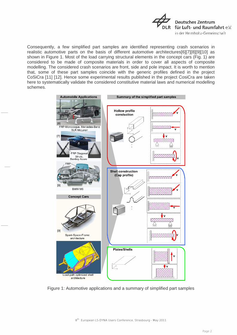
Consequently, a few simplified part samples are identified representing crash scenarios in realistic automotive parts on the basis of different automotive architectures[6][7][8][9][10] as shown in Figure 1. Most of the load carrying structural elements in the concept cars (Fig. 1) are considered to be made of composite materials in order to cover all aspects of composite modelling. The considered crash scenarios are front, side and pole impact. It is worth to mention that, some of these part samples coincide with the generic profiles defined in the project CoSiCra [11] [12]. Hence some experimental results published in the project CosiCra are taken here to systematically validate the considered constitutive material laws and numerical modelling schemes.
Figure 1: Automotive applications and a summary of simplified part samples
8th European LS-DYNA Users Conference, Strasbourg - May 2011
Page 3
Theoretical background - Constitutive Material Models The failure behaviour of carbon fibre reinforced plastics depends on the interaction of various failure mechanisms, particularly matrix cracking, delamination, fibre buckling, fibre tensile fracture and heat dissipation due to contact friction. Material models that appropriately build the exact physical behaviour at micro-scale belong to the state-of-the-art research topics; it also requires very large computational effort. Although the current analysis methods do not capture exact physical behaviour of the structure, it is possible to consider different failure mechanisms as well as the interaction of different stress components in a “macro-scale” to predict the structural response. This enables the current methods suitable for large scale industrial size problems. The basic ideas in different state-of-the-art material models based in LS-DYNA will be discussed short in the following. For a detailed description, the interested reader is referred to LS-DYNA Theory manual [13]. Material Model 54 (MAT_054) This criterion differentiates failure due to tensile fibre mode, compressive fibre mode, tensile matrix mode and compressive matrix mode based on Chang/Chang failure criterion. The stress interactions leading to laminate failure are coupled in all failure modes other than compressive fibre mode. Failure occurs in any one of these four ways:
• Chang/Chang failure criteria in the tensile fibre mode is satisfied • The allowable strain limit in the fibre direction is exceeded • The effective strain is greater than the allowed parameter • The element time step size is smaller that the critically defined value
If the failure has occurred in all of the laminate layers, then the element is deleted. There are also several “adjustment parameters” in this criterion which shall enable reasonable representation of the structural behaviour. Especially with the parameter “SOFT”, it is possible to reduce the strength and stiffness properties of all elements, which are adjacent to a damaged element. Hence in combination with “trigger elements”, a controlled crash process can be initiated. The trigger elements usually fail at first, which reduces the stiffness and strength of its adjacent elements and therefore the so-called crash front can be generated. This model does not account for transverse shear, however delamination can be accounted through special contact algorithms or modelling methods. Material Model 55 (MAT_055) This model is very close to the formulation of material model 54; except for the difference that it uses the Tsai-Wu criterion for the matrix failure. This model also does not account for transverse shear. Material Model 58 (MAT_058) This model works on the basis of strain based failure surfaces. If the maximum effective strain is reached, then the corresponding layer in the element is deleted. A very important feature of this model is the possibility to set-up a post-damage adjustment parameter (e.g. SLIMx), which determines the residual strength of each layer of laminate after elastic damage. Hence an elasto-plastic material behaviour can be realized. It is also possible in this model to consider failure due to delamination using special contact algorithms.
8th European LS-DYNA Users Conference, Strasbourg - May 2011
Page 4
Material Model 59 (MAT_059) This model also works on the basis of failure surfaces. This is an elastic–plastic material model [14]. It is capable of modelling the progressive failure of the material due to any of several failure criterion including tension/compression in the longitudinal and transverse directions, compression in the through-thickness direction, and through-thickness shear [15]. Adjustment parameters such as “SOFT” and time step size for automatic element deletion were also included in this model. Modelling parameters and Material properties Even though there are considerable differences in the required data in each of the constitutive material models discussed above, the necessary parameters in all models can be grouped in to;
• Material specific strength data in tension, compression and shear • Material specific stiffness data in tension, compression and shear • and importantly the criterion specific “adjustment data”
The quality of the simulation results and therefore the predictability of structural response depend on three main factors:
• Correctness of the material specific strength and stiffness data • Choice of adjustment data in each of the criterion • Choice of modelling parameters; primarily the element size, contact algorithm, filtering,
test speed and trigger characteristics The first and foremost problem lies in obtaining a reasonable material specific data. The measured material data for instance from a coupon test is not strictly a intrinsic material property, but a property depending on the type of test bench, geometry of test specimens, test speed, the developing strain gradients through local deformation and engineering interpretation. Furthermore, obtaining a comprehensive strain rate data for an almost infinitely possible composite combination is a tedious task. Hence the choice of the “adjustment data” and modelling parameters remains an only alternative in obtaining acceptable simulation results. The material properties interpreted from coupon tests of carbon fibre reinforced composite specimens are given in Table 1. The thicknesses of prepreg of uni-directional fibre and fabric materials are 0.125 mm and 0.3 mm respectively.
Material Properties Uni-directional Fibre Fabric (MPa) (MPa) Young's Modulus (a direction) 160000 70000 Young's Modulus (b direction) 9000 70000 Poisson's ratio (ba) 0.01892 0.05 Shear modulus (ab) 7620 7630 Longtitudinal tensile strength (a direction) 2100 850 Longtitudinal compressive strength (a direction) 1450 800 Transverse tensile strength (b direction) 87 850 Transverse compressive strength (b direction) 180 800 Shear strength (ab direction) 170 113
8th European LS-DYNA Users Conference, Strasbourg - May 2011
Page 5
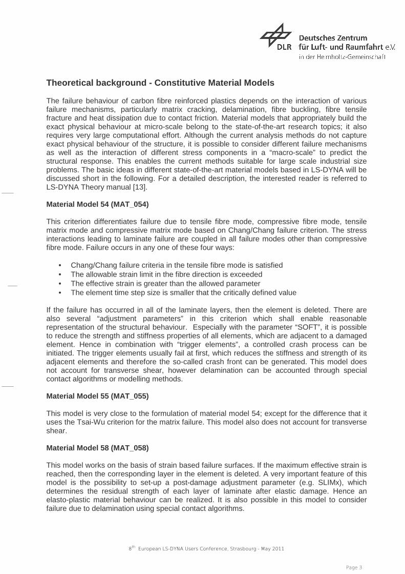
Table 1: Material properties Analysis with simplified part samples Four different simplified part sample configurations are considered in this paper and are compared with the experimental results. The laminate lay-up is [± 45ºC, ± 45ºC, 0/90ºC, 0/90ºC, 0ºC, 0ºC, 0ºC, 0ºC]s . The initial impact velocities in the simulations are calculated in accordance with experimental setups, as described in the project [11]. A special emphasis is given to the material model MAT_054 in this paper, as it has comparatively a large number of “adjustment parameters” and therefore enables a better demonstration of calibrating possibilities in numerical simulation. Tests with a rectangular hollow profile, direct crushing load Crushing represents one of the most complex failure phenomenons and therefore the applicability of material models MAT_054, MAT_055, MAT_058 and MAT_059 is verified here. Figure 2 shows the principle and a typical FE-Model setup in all simulations.
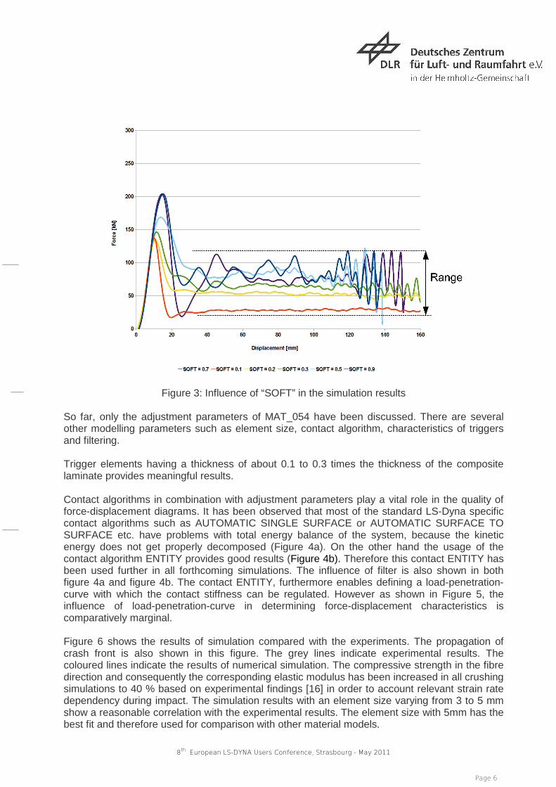
Figure 2: FE-Model-Setup of a rectangular profile Material Model 54 (MAT_054) One of the most relevant adjustment parameter in this model is the “SOFT” value which controls the crash front. Figure 3 shows the influence of the “SOFT” value in the results of the numerical simulation. It can be clearly seen from the force-displacement diagram, that the amount of energy absorbed by the system is significantly influenced by the choice of this parameter. There are several other considerable influencing parameters such as DFAILM, DFAILS, DFAILT and DFAILC. These are strain values in compression and tension mode of fibre and matrix and hence can be adjusted meaningfully based on the stress-strain diagrams from coupon tests. Following values have been set in most of the simulations considered in this paper; DFAILM = 0.0093, DFAILS = 0.135, DFAILT = 0.0121 and DFAILC = -0.0093. The effective failure strain criteria EFS is not considered here. Other adjustment parameters such as ALPH, BETA, FBRT and YFAC have relatively smaller influences based on our simulative experiments.
8th European LS-DYNA Users Conference, Strasbourg - May 2011
Page 6
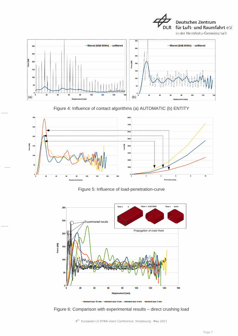
Figure 3: Influence of “SOFT” in the simulation results So far, only the adjustment parameters of MAT_054 have been discussed. There are several other modelling parameters such as element size, contact algorithm, characteristics of triggers and filtering. Trigger elements having a thickness of about 0.1 to 0.3 times the thickness of the composite laminate provides meaningful results. Contact algorithms in combination with adjustment parameters play a vital role in the quality of force-displacement diagrams. It has been observed that most of the standard LS-Dyna specific contact algorithms such as AUTOMATIC SINGLE SURFACE or AUTOMATIC SURFACE TO SURFACE etc. have problems with total energy balance of the system, because the kinetic energy does not get properly decomposed (Figure 4a). On the other hand the usage of the contact algorithm ENTITY provides good results (Figure 4b). Therefore this contact ENTITY has been used further in all forthcoming simulations. The influence of filter is also shown in both figure 4a and figure 4b. The contact ENTITY, furthermore enables defining a load-penetration-curve with which the contact stiffness can be regulated. However as shown in Figure 5, the influence of load-penetration-curve in determining force-displacement characteristics is comparatively marginal. Figure 6 shows the results of simulation compared with the experiments. The propagation of crash front is also shown in this figure. The grey lines indicate experimental results. The coloured lines indicate the results of numerical simulation. The compressive strength in the fibre direction and consequently the corresponding elastic modulus has been increased in all crushing simulations to 40 % based on experimental findings [16] in order to account relevant strain rate dependency during impact. The simulation results with an element size varying from 3 to 5 mm show a reasonable correlation with the experimental results. The element size with 5mm has the best fit and therefore used for comparison with other material models.
8th European LS-DYNA Users Conference, Strasbourg - May 2011
Page 7
Figure 4: Influence of contact algorithms (a) AUTOMATIC (b) ENTITY
Figure 5: Influence of load-penetration-curve
Figure 6: Comparison with experimental results – direct crushing load
8th European LS-DYNA Users Conference, Strasbourg - May 2011
Page 8
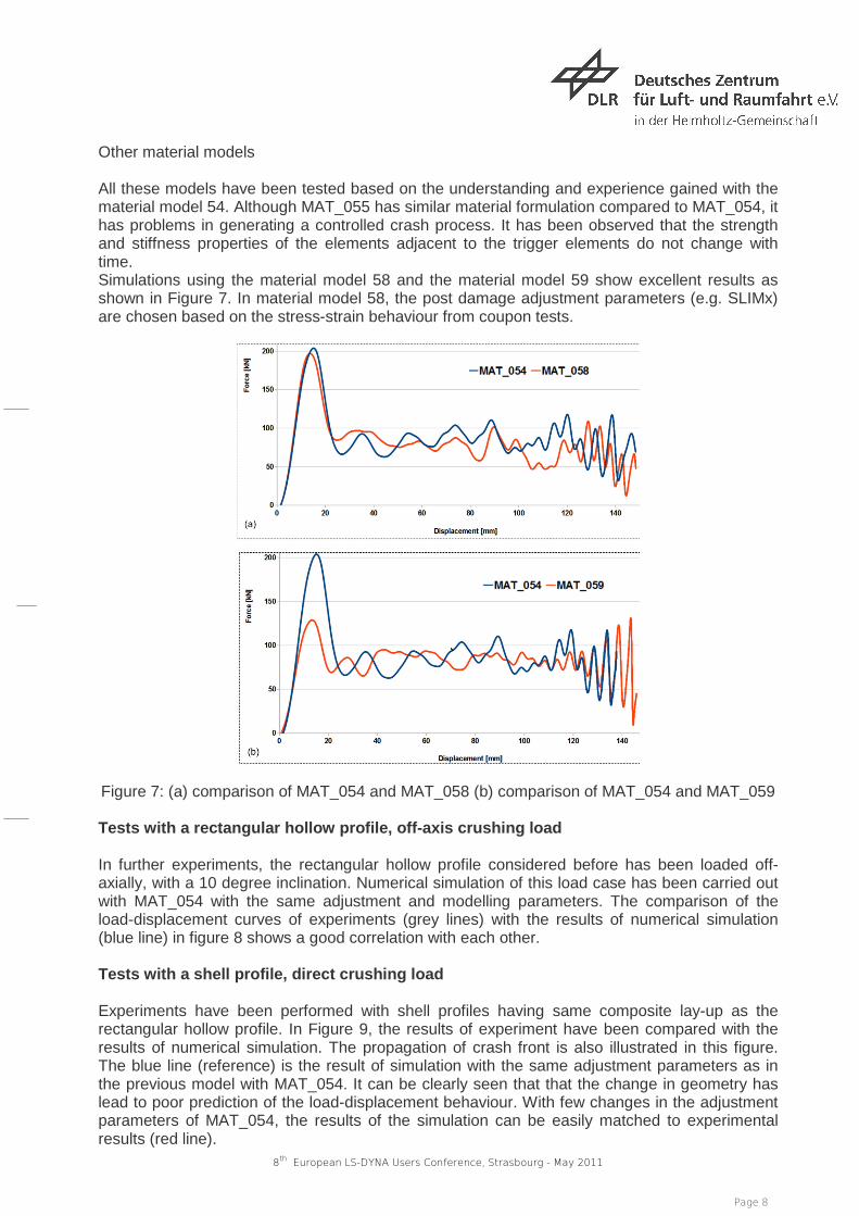
Other material models All these models have been tested based on the understanding and experience gained with the material model 54. Although MAT_055 has similar material formulation compared to MAT_054, it has problems in generating a controlled crash process. It has been observed that the strength and stiffness properties of the elements adjacent to the trigger elements do not change with time. Simulations using the material model 58 and the material model 59 show excellent results as shown in Figure 7. In material model 58, the post damage adjustment parameters (e.g. SLIMx) are chosen based on the stress-strain behaviour from coupon tests.
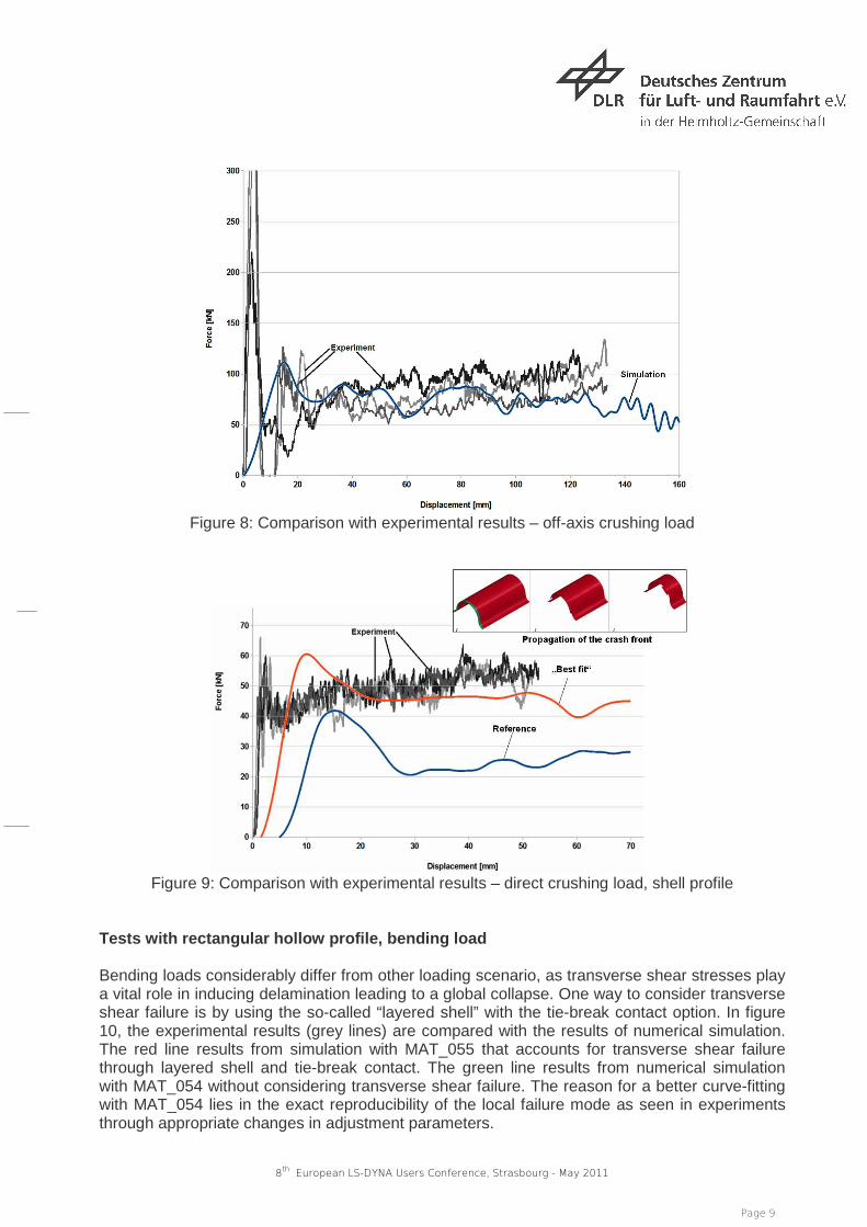
Figure 7: (a) comparison of MAT_054 and MAT_058 (b) comparison of MAT_054 and MAT_059 Tests with a rectangular hollow profile, off-axis crushing load In further experiments, the rectangular hollow profile considered before has been loaded off-axially, with a 10 degree inclination. Numerical simulation of this load case has been carried out with MAT_054 with the same adjustment and modelling parameters. The comparison of the load-displacement curves of experiments (grey lines) with the results of numerical simulation (blue line) in figure 8 shows a good correlation with each other. Tests with a shell profile, direct crushing load Experiments have been performed with shell profiles having same composite lay-up as the rectangular hollow profile. In Figure 9, the results of experiment have been compared with the results of numerical simulation. The propagation of crash front is also illustrated in this figure. The blue line (reference) is the result of simulation with the same adjustment parameters as in the previous model with MAT_054. It can be clearly seen that that the change in geometry has lead to poor prediction of the load-displacement behaviour. With few changes in the adjustment parameters of MAT_054, the results of the simulation can be easily matched to experimental results (red line).
8th European LS-DYNA Users Conference, Strasbourg - May 2011
Page 9
Figure 8: Comparison with experimental results – off-axis crushing load
Figure 9: Comparison with experimental results – direct crushing load, shell profile
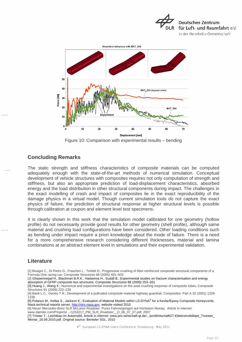
Tests with rectangular hollow profile, bending load Bending loads considerably differ from other loading scenario, as transverse shear stresses play a vital role in inducing delamination leading to a global collapse. One way to consider transverse shear failure is by using the so-called “layered shell” with the tie-break contact option. In figure 10, the experimental results (grey lines) are compared with the results of numerical simulation. The red line results from simulation with MAT_055 that accounts for transverse shear failure through layered shell and tie-break contact. The green line results from numerical simulation with MAT_054 without considering transverse shear failure. The reason for a better curve-fitting with MAT_054 lies in the exact reproducibility of the local failure mode as seen in experiments through appropriate changes in adjustment parameters.
8th European LS-DYNA Users Conference, Strasbourg - May 2011
Page 10
Figure 10: Comparison with experimental results – bending
Concluding Remarks The static strength and stiffness characteristics of composite materials can be computed adequately enough with the state-of-the-art methods of numerical simulation. Conceptual development of vehicle structures with composites requires not only computation of strength and stiffness, but also an appropriate prediction of load-displacement characteristics, absorbed energy and the load distribution in other structural components during impact. The challenges in the exact modelling of crash and impact of composites lie in the exact reproducibility of the damage physics in a virtual model. Though current simulation tools do not capture the exact physics of failure, the prediction of structural response at higher structural levels is possible through calibration at coupon and element level test specimens. It is clearly shown in this work that the simulation model calibrated for one geometry (hollow profile) do not necessarily provide good results for other geometry (shell profile), although same material and crushing load configurations have been considered. Other loading conditions such as bending under impact require a priori knowledge about the mode of failure. There is a need for a more comprehensive research considering different thicknesses, material and lamina combinations at an abstract element level in simulations and their experimental validation. Literature [1] Bisagni C., Di Pietro G., Fraschini L., Terletti D.; Progressive crushing of fiber-reinforced composite structural components of a Formula One racing car, Composite Structures 68 (2005) 491–503 [2] Ghasemnejad H., Blackman B.R.K., Hadavinia H., Sudall B.; Experimental studies on fracture characterisation and energy absorption of GFRP composite box structures, Composite Structures 88 (2009) 253–261 [3] Huang J., Wang X.; Numerical and experimental investigations on the axial crushing response of composite tubes, Composite Structures 91 (2009) 222–228 [4] Bank L.C., Gentry T.R.; Development of a pultruded composite material highway guardrail, Composites: Part A 32 (2001) 1329-1338 [5] Polanco M., Kellas S., Jackson K.; Evaluation of Material Models within LS-DYNA® for a Kevlar/Epoxy Composite Honeycomb, Nasa technical reports server, http://ntrs.nasa.gov, website visited 2010 [6] Neuer Mercedes-Benz SLR McLaren Roadster: Pures Fahrvergnügen auf höchstem Niveau, Article in internet: www.daimler.com/Projects/…/1253217_PM_SLR_Roadster__D_06_07_07.pdf, 2007 [7] Tröster T.; Leichtbau im Automobil, Article in internet: www.pro-wirtschaft-gt.de/.../proWirtschaftGT-Elektromobilitaet_Troester_ Mense_16.09.2010.pdf, Original source: Benteler SGL, 2010
8th European LS-DYNA Users Conference, Strasbourg - May 2011
Page 11
[8] Schlarb A.K.; Verbundwerkstoffe mit Kunststoffmatrix im Automobilbau – Stand & Entwicklungspotenziale, Article in internet: www.automanager.de/BayernInnovativ/.../pdf/schlarb.pdf, 2007 [9] Schöll R., Friedrich H.E., Kopp G., Kopp G.; Innovative Fahrzeugstruktur in Spant- und Space-Frame-Bauweise, Sonderdruck aus ATZproduktion, 2008 [10] Krishnamoorthy S. K.; Methodology for light weight conception of vehicle bodies using topology optimization, DLR internal report, Project MS 2200-01, 2010 [11] Friedrich, H.E. (approved); CoSiCra, Final report of the research project: Entwicklung und Verifikation einer Composite-Simulationsmethodik zur Vorhersage des Crashverhaltens von hoch belasteten Fahrzeugstrukturen, 2010 [12] Holzapfel, M., Kopp G., Adamski P., Elsenhans H., Hambrecht T., Döll J.; Untersuchungen zur Modellierung von Strukturen aus FKV unter Crashbelastung mit Hilfe von Mehrschalenmodellierungen, 7. LS-DYNA Anwenderforum, Bamberg 2008 [13] LS-DYNA Keyword user’s manual, Livermore Software Technology Corporation, 2009 [14] Kotzakolios T., Vlachos D.E., Kostopoulos V.; Blast response of metal composite laminate fuselage structures using finite element modelling, Composite Structures 93 (2011) 665–681 [15] LeBlanc J., Shukla A.; Dynamic response and damage evolution in composite materials subjected to underwater explosive loading: An experimental and computational study, Composite Structures 92 (2010) 2421–2430 [16] Bing, Q., Sun, C.T.; Modeling and testing strain rate-dependent compressive strength of carbon/epoxy composites, Composites Science and Technology 65 (2005) 2481–2491