Embed Size (px)
Citation preview
Plasma and Fusion Research: Regular Articles Volume 14, 3403154 (2019)
Predictions of Plasma Behavior Due to Pellet Injection for FutureThailand Tokamak∗)
Jiraporn PROMPING, Apiwat WISITSORASAK1,2), Boonyarit CHATTHONG3),Siriyaporn SANGAROON4), Roppon PICHA and Atsushi FUKUYAMA5)
Thailand Institute of Nuclear Technology, Bangkok, Thailand1)Department of Physics, Faculty of Science, King Mongkut’s University of Technology Thonburi, Bangkok, Thailand
2)Theoretical and Computational Science Center, King Mongkut’s University of Technology Thonburi, Bangkok, Thailand3)Department of Physics, Faculty of Science, Prince of Songkla University, Songkhla, Thailand
4)Department of Physics, Mahasarakham University, Mahasarakham, Thailand5)Department of Nuclear Engineering, Kyoto University, Kyoto 615-8540, Japan
(Received 9 January 2019 / Accepted 25 June 2019)
Thailand Institute of Nuclear Technology (TINT) was donated HT-6M tokamak by Institute of PlasmaPhysics, Chinese Academy of Sciences (ASIPP), China. The machine will be upgraded and installed in Nakorn-Nayok, Thailand in the near future to kick start on research and human development in the country. In the firstphase of operation there will be no external heating, and hydrogen plasma in ohmic phase will be studied. Pelletinjection system will be one of the main components to be developed. In this work, the investigation of injectionspeed, size of a pellet and the angle of injection is conducted by using simulations for providing initial results ofthe effect of pellets on the plasma. TASK/TR integrated modeling code is used for predicting the plasma profiles.In the core area, the anomalous transport is computed by either the theory-based current diffusive ballooningmode (CDBM) model or the Multi-Mode-95 (MMM95) model. The interaction of the pellet and the backgroundplasma is analyzed by HPI2 code which employed the neutral gas shielding (NGS) ablation model including∇B-drift effect. This work only considers the injection of a single pellet whose radius is between 0.2 - 0.4 mm.The injection speed is varied in the range of 100 - 1,000 m/s. Injections from both low-field and high-field sidesand also investigated. The results illustrate that the pellet can penetrate deeply into the plasma core.
c© 2019 The Japan Society of Plasma Science and Nuclear Fusion Research
Keywords: Thailand tokamak, pellet injection, ∇B-drift effect, neutral gas shielding model (NGS)
DOI: 10.1585/pfr.14.3403154
1. IntroductionHT-6M was a small tokamak (the major radius is
0.65 m, the minor radius is 0.2 m, the plasma current is150 kA and the toroidal field is 1.5 T) and it was formerlydeveloped and operated by Institute of Plasma Physics,Chinese Academy of Sciences (ASIPP), China [1]. Thismachine will be donated to Thailand for research and hu-man resource development. Initially, it will be installedwith only basics diagnostics and magnetic components, noexternal heating and fueling yet. Some components, suchas additional diagnostic systems, high voltage power sup-ply, and external heating systems, will be re-designed andupgraded before starting the new experimental campaign.An injection system of high-speed frozen pellets of hydro-gen or deuterium directly into the plasma core is anotherkey system for efficient fueling. The goal of this work is toinvestigate the effects of the pellet injection onto HT-6Mplasma by using an integrated predictive modeling code
author’s e-mail: [email protected]∗) This article is based on the presentation at the 27th International TokiConference (ITC27) & the 13th Asia Pacific Plasma Theory Conference(APPTC2018).
TASK/TR [2]. The results can provide insightful informa-tion for planning of experimental campaign and the devel-opment of the injection system.
Comparing to gas puffing method, the pellet injectionyields deeper penetration depth [3, 4]. Pellet injection hasalso been demonstrated to improve plasma confinement inseveral experiments [5–7]. It can be also used to reducerecycling but increase the strong peak of electron densityprofile and the confinement time which can lead to increaseof the fusion power gain. The effect of the pellet injec-tion onto tokamak plasmas depends on many factors suchas machine size, pellet size, injection speed and plasmashape [8, 9]. Injection direction also directly affects the re-sponse of the plasma after the injection. Based on previousstudies, the pellet injection experiments in JET and TFTRhad shown slight improvement of plasma density when in-jected from the low-field side (LFS) [10]. On the otherhand, pellets injected from the high-field side (HFS) yieldsdeeper penetration depth. Thus, better fusion performancecan be expected by the HFS injection [11–14].
In this work, simulations are carried out with plasma
c© 2019 The Japan Society of PlasmaScience and Nuclear Fusion Research
3403154-1
Plasma and Fusion Research: Regular Articles Volume 14, 3403154 (2019)
parameters based on the previous design of the HT-6Mtokamak, including R = 65 cm, a = 20 cm, BT = 1.5 T,ne = 1 × 10¹⁹ m−3 and Ip = 150 kA [1]. Since the firstphase of the future Thailand tokamak will have no ex-ternal heating, an ohmic plasma is expected. TASK/TRintegrated predictive modeling code is used to carry outthis investigation. The core transport calculation used inthis work is either the theory-based current diffusive bal-looning mode (CDBM) model [15] or the Multi-Mode-95(MMM95) [16] model. Three different scenarios of thepellet injection in HT-6M plasma are reported. Firstly, theeffects of a single pellet with a fixed size injected with var-ious injection speeds are reported. Then we study the sen-sitivity of varying pellet sizes and injection speeds. Lastly,the investigation of the effect of the inject direction is con-ducted.
This paper is organized as follows: brief descriptionsof modeling and simulation method are given in the nextsection. In section 3, the simulation results and discussionsare presented. Section 4 summarizes this study.
2. Modeling and SimulationMethodology
2.1 TASK/TR integrated modelling codeThe TASK/TR code is a one-dimensional tokamak
transport code that has been developed to analyze the timeevolution of a burning plasma accompanied with fusion re-action [2]. In this work, the plasma transport in the coreregion is described by using the current diffusive balloon-ing mode (CDBM) and the multimode (MMM95) coretransport model. The CDBM model [15] is based on thetheory of self-sustained turbulence due to the ballooningmode [17] driven by the turbulent current diffusivity. TheMMM95 model [16] consists of the Weiland model forthe ion temperature gradient (ITG) and trapped electronmodes (TEM), the Guzdar-Drake model for drift-resistiveballooning modes, as well as a smaller contribution fromkinetic ballooning modes.
2.2 Pellet ablation and ∇B-induced driftmodels
The neutral gas shielding (NGS) model was proposedby Parks and Turnbull [18] to solve the problem of a solidhydrogen pellet ablation in a plasma. It is considered thatthe pellet is ablated by the mono-energetic electrons energyflux based on a symmetric expansion and the steady stateapproximations. As a result, the ablation rate (dN/dt) isgiven by:
dNdt= 1.12 × 10⁶n0.3333
e T 1.64e r1.33
p M−0.333i , (1)
where ne and Te are the electron density in cm−3 and tem-perature in eV, respectively. rp denotes pellet radius in cmand Mi is the mass of the pellet material in atomic unit.
After the pellet is ablated, the neutral cloud that
formed around the pellet also experiences the apparent
drift in the radial direction. This drift is caused by−→E × −→B
effect which arises from the ionized part of the ablation
cloud due to−→∇B and curvature-induced charged particle
drift [19]. The cross-field drift velocity (VD) can be com-puted as:
V̇D =2(p0 − p∞)
n0miR− VD
2B2φ
μ0CAn0miZ0, (2)
where p0 and p∞ denotes the initial pressure inside the highdensity blob of plasma and the pressure of the backgroundplasma, respectively. n0 refers to the initial density of theplasmoid, Z0 is the initial thickness of the ablatant cloud,mi is the ion mass, and CA is the speed of the Alfven wave[20].
The HPI2 pellet fueling code is able to analyze thepellet deposition profile directly. However, it still requiresthe plasma profile such as the temperature and density asinputs. These information of the plasma before the pel-let event can be determined by the transport code. Thetransport code also allows to study plasma response af-ter the pellet injection. In order to account for the abla-tion of the pellet material and ∇B-induced drift effect, weemploy the predictive simulation code HPI2 developed byPegourie and co-workers [20] and it is integrated with theTASK/TR code.
3. Simulation Results and DiscussionsIn this part, we use the TASK/TR code to simulate the
plasma in the core of the future Thailand Tokamak. Theplasma is assumed to be hydrogen and it has the electrondensity of 1019 m−3. There is no external heating in thesesimulations. The transport in the core region is a combi-nation of the neoclassical transport which is computed byNCLASS module [21] and the anomalous transport, whichis computed by CDBM or MMM95 transport model.
In the previous experiment of HT-6M [22], the ma-chine was equipped with the pellet injector system. It wasdesigned to produce hydrogen pellets in a cylindrical shapewith 0.6 - 0.8 mm in diameter, and 0.8 mm in length. Thepellets were delivered into the tokamak by using a pneu-matic system and it was able to achieve maximum speedof 1.4 km/s approximately. The bulk plasma electron den-sity for normal operations was around 1013 cm−3 and thecentral electron temperature was about 500 eV.
Three different scenarios of the pellet injection areconducted and reported: 1) the effect of the injectionspeeds for a single pellet whose radius is 3.78× 10⁻⁴ m, 2)the sensitivity study of the effect of varying both injectionspeed and pellet size, and 3) the analysis of the varying in-jection direction. Note that we only focus on the responseof the plasma after a single hydrogen pellet was injected.
3.1 The analyzing of fixed pellet size withvarying injection speeds
We first performed simulations of the pellet injec-
3403154-2
Plasma and Fusion Research: Regular Articles Volume 14, 3403154 (2019)
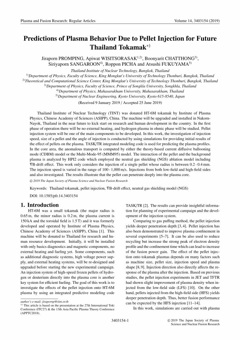
tion based on the previous design and compare with theprevious experimental results [22]. Based on their de-sign, the cylindrical pellet of size 0.6 mm diameter and0.8 mm length is equivalent to a spherical of radius size3.78 × 10−4 m. A single hydrogen pellet is launched fromthe LFS into the HT-6M plasma with two injection speedsof 100 m/s (low speed) and 600 m/s (high speed).
The electron temperature and density profile areshown in Figs. 1 and 2 as a function of time and normal-ized minor radius. The CDBM model is used for the core
Fig. 1 The electron temperature and density as a function oftime with the pellet velocity of 100 m/s (top) and 600 m/s(bottom).
Fig. 2 The electron temperature (top) and electron density (bot-tom) profiles as a function of normalized minor radius,before and after pellet injection with the pellet velocity of100 m/s (red-solid) and 600 m/s (blue-solid), respectively.The core transport model is based on CDBM model.
transport. The simulation results from both discharges arein Ohmic mode. These results show that pellets increasethe electron density at the center from 0.200× 10²⁰ m−3 upto 0.370 × 10²⁰ m−3 and 0.200 × 10²⁰ m−3 up to 0.475 ×10²⁰ m−3 for the launching speeds of 100 m/s and 600 m/s,respectively.
It is also observed that the pellets decrease the centralelectron temperature from 480 eV to 358 eV for the injec-tion speed of 100 m/s, and from 480 eV to 248 eV for theinjection speed of 600 m/s. Both temperature and densityof the plasma return to their previous levels after 0.1 msapproximately. The simulation results of the peak valueof electron density and temperature agree with the samerange of the experimental results [22].
3.2 Sensitivity study of the pellet size and in-jection speed
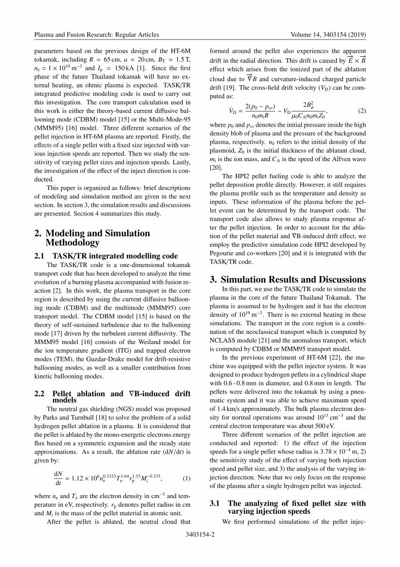
It is known that penetration depth and the depositedmass of the pellet depends on the pellet size, injectionspeed, injection angle, and the background plasma condi-tion as well. This part investigates the sensitivity of thevariation of the pellet size and injection speed. A singlespherical pellet is launched from the LFS whose size isvaried between 0.1 and 0.4 mm and the injection speed ischanged between 100 to 1000 m/s.
Figure 3 shows the deposited mass of the pellet on thebackground plasma as predicted by the HPI2 code for twodifferent core transport models: CDBM and MMM95. Asseen in these graphs, the highest deposition fraction thatcan be achieved from both models is approximately 0.6.Some of the mass that does not remain in the core plasma
is lost due to the−→∇B effect in the radial direction.
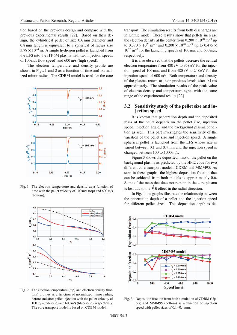
In Fig. 4, the graphs illustrate the relationship betweenthe penetration depth of a pellet and the injection speedfor different pellet sizes. This deposition depth is de-
Fig. 3 Deposition fraction from both simulation of CDBM (Up-per) and MMM95 (bottom) as a function of injectionspeed with pellet sizes of 0.1 - 0.4 mm.
3403154-3
Plasma and Fusion Research: Regular Articles Volume 14, 3403154 (2019)
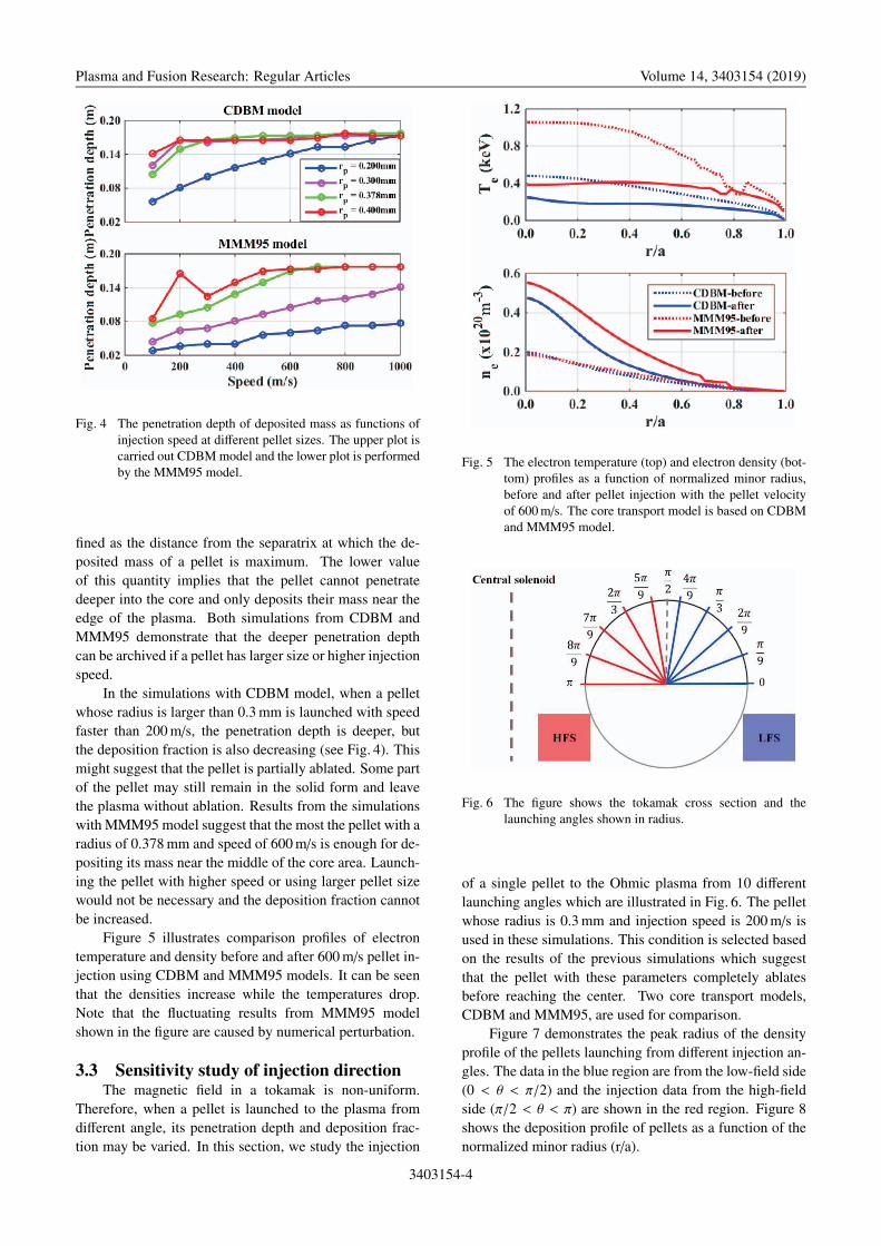
Fig. 4 The penetration depth of deposited mass as functions ofinjection speed at different pellet sizes. The upper plot iscarried out CDBM model and the lower plot is performedby the MMM95 model.
fined as the distance from the separatrix at which the de-posited mass of a pellet is maximum. The lower valueof this quantity implies that the pellet cannot penetratedeeper into the core and only deposits their mass near theedge of the plasma. Both simulations from CDBM andMMM95 demonstrate that the deeper penetration depthcan be archived if a pellet has larger size or higher injectionspeed.
In the simulations with CDBM model, when a pelletwhose radius is larger than 0.3 mm is launched with speedfaster than 200 m/s, the penetration depth is deeper, butthe deposition fraction is also decreasing (see Fig. 4). Thismight suggest that the pellet is partially ablated. Some partof the pellet may still remain in the solid form and leavethe plasma without ablation. Results from the simulationswith MMM95 model suggest that the most the pellet with aradius of 0.378 mm and speed of 600 m/s is enough for de-positing its mass near the middle of the core area. Launch-ing the pellet with higher speed or using larger pellet sizewould not be necessary and the deposition fraction cannotbe increased.
Figure 5 illustrates comparison profiles of electrontemperature and density before and after 600 m/s pellet in-jection using CDBM and MMM95 models. It can be seenthat the densities increase while the temperatures drop.Note that the fluctuating results from MMM95 modelshown in the figure are caused by numerical perturbation.
3.3 Sensitivity study of injection directionThe magnetic field in a tokamak is non-uniform.
Therefore, when a pellet is launched to the plasma fromdifferent angle, its penetration depth and deposition frac-tion may be varied. In this section, we study the injection
Fig. 5 The electron temperature (top) and electron density (bot-tom) profiles as a function of normalized minor radius,before and after pellet injection with the pellet velocityof 600 m/s. The core transport model is based on CDBMand MMM95 model.
Fig. 6 The figure shows the tokamak cross section and thelaunching angles shown in radius.
of a single pellet to the Ohmic plasma from 10 differentlaunching angles which are illustrated in Fig. 6. The pelletwhose radius is 0.3 mm and injection speed is 200 m/s isused in these simulations. This condition is selected basedon the results of the previous simulations which suggestthat the pellet with these parameters completely ablatesbefore reaching the center. Two core transport models,CDBM and MMM95, are used for comparison.
Figure 7 demonstrates the peak radius of the densityprofile of the pellets launching from different injection an-gles. The data in the blue region are from the low-field side(0 < θ < π/2) and the injection data from the high-fieldside (π/2 < θ < π) are shown in the red region. Figure 8shows the deposition profile of pellets as a function of thenormalized minor radius (r/a).
3403154-4
Plasma and Fusion Research: Regular Articles Volume 14, 3403154 (2019)
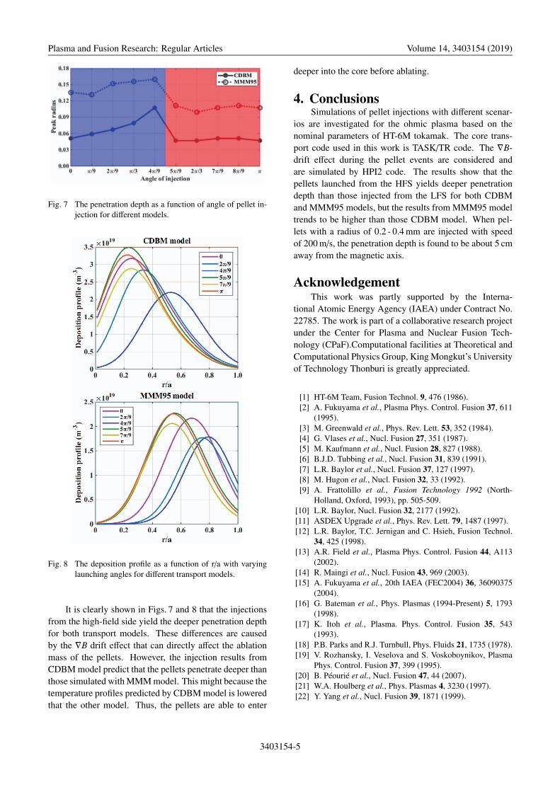
Fig. 7 The penetration depth as a function of angle of pellet in-jection for different models.
Fig. 8 The deposition profile as a function of r/a with varyinglaunching angles for different transport models.
It is clearly shown in Figs. 7 and 8 that the injectionsfrom the high-field side yield the deeper penetration depthfor both transport models. These differences are causedby the ∇B drift effect that can directly affect the ablationmass of the pellets. However, the injection results fromCDBM model predict that the pellets penetrate deeper thanthose simulated with MMM model. This might because thetemperature profiles predicted by CDBM model is loweredthat the other model. Thus, the pellets are able to enter
deeper into the core before ablating.
4. ConclusionsSimulations of pellet injections with different scenar-
ios are investigated for the ohmic plasma based on thenominal parameters of HT-6M tokamak. The core trans-port code used in this work is TASK/TR code. The ∇B-drift effect during the pellet events are considered andare simulated by HPI2 code. The results show that thepellets launched from the HFS yields deeper penetrationdepth than those injected from the LFS for both CDBMand MMM95 models, but the results from MMM95 modeltrends to be higher than those CDBM model. When pel-lets with a radius of 0.2 - 0.4 mm are injected with speedof 200 m/s, the penetration depth is found to be about 5 cmaway from the magnetic axis.
AcknowledgementThis work was partly supported by the Interna-
tional Atomic Energy Agency (IAEA) under Contract No.22785. The work is part of a collaborative research projectunder the Center for Plasma and Nuclear Fusion Tech-nology (CPaF).Computational facilities at Theoretical andComputational Physics Group, King Mongkut’s Universityof Technology Thonburi is greatly appreciated.
[1] HT-6M Team, Fusion Technol. 9, 476 (1986).[2] A. Fukuyama et al., Plasma Phys. Control. Fusion 37, 611
(1995).[3] M. Greenwald et al., Phys. Rev. Lett. 53, 352 (1984).[4] G. Vlases et al., Nucl. Fusion 27, 351 (1987).[5] M. Kaufmann et al., Nucl. Fusion 28, 827 (1988).[6] B.J.D. Tubbing et al., Nucl. Fusion 31, 839 (1991).[7] L.R. Baylor et al., Nucl. Fusion 37, 127 (1997).[8] M. Hugon et al., Nucl. Fusion 32, 33 (1992).[9] A. Frattolillo et al., Fusion Technology 1992 (North-
Holland, Oxford, 1993), pp. 505-509.[10] L.R. Baylor, Nucl. Fusion 32, 2177 (1992).[11] ASDEX Upgrade et al., Phys. Rev. Lett. 79, 1487 (1997).[12] L.R. Baylor, T.C. Jernigan and C. Hsieh, Fusion Technol.
34, 425 (1998).[13] A.R. Field et al., Plasma Phys. Control. Fusion 44, A113
(2002).[14] R. Maingi et al., Nucl. Fusion 43, 969 (2003).[15] A. Fukuyama et al., 20th IAEA (FEC2004) 36, 36090375
(2004).[16] G. Bateman et al., Phys. Plasmas (1994-Present) 5, 1793
(1998).[17] K. Itoh et al., Plasma. Phys. Control. Fusion 35, 543
(1993).[18] P.B. Parks and R.J. Turnbull, Phys. Fluids 21, 1735 (1978).[19] V. Rozhansky, I. Veselova and S. Voskoboynikov, Plasma
Phys. Control. Fusion 37, 399 (1995).[20] B. Péourié et al., Nucl. Fusion 47, 44 (2007).[21] W.A. Houlberg et al., Phys. Plasmas 4, 3230 (1997).[22] Y. Yang et al., Nucl. Fusion 39, 1871 (1999).
3403154-5