Embed Size (px)
Citation preview

228 IEEE TRANSACTIONS ON POWER ELECTRONICS, VOL. 25, NO. 1, JANUARY 2010
Predictive Direct Power Control of Three-PhasePulsewidth Modulation (PWM) Rectifier Using
Space-Vector Modulation (SVM)Abdelouahab Bouafia, Jean-Paul Gaubert, Member, IEEE, and Fateh Krim, Senior Member, IEEE
Abstract—In this paper, we present a direct power control(DPC) of three-phase pulsewidth modulation rectifier with con-stant switching frequency using space-vector modulation (SVM).The developed DPC scheme is based on the predictive control strat-egy to achieve direct control of instantaneous active and reactivepower of the converter. For this purpose, at the beginning of eachswitching period, the required rectifier average voltage vector al-lowing the cancellation of active and reactive power tracking er-rors, at the end of the switching period, is calculated by means ofpredictive control algorithm in the sense of deadbeat control. Themain advantages of the proposed control, compared to the workspublished in this subject, are that no need to use predefined switch-ing table and voltage vector or virtual flux position, PI-based activeand reactive power control loops are not necessary and constant-switching frequency. The proposed predictive direct power controlwas tested both in simulations and experimentally and comparedwith DPC using switching table. Results have proved excellent per-formance, and verify the validity of the proposed DPC scheme,which is much better than conventional DPC using switchingtable.
Index Terms—Deadbeat control, direct power control, instanta-neous powers, predictive control, pulsewidth modulation (PWM)rectifier, space-vector modulation (SVM), unity power factor.
I. INTRODUCTION
R ESEARCH interest in bi-directional three-phase pulse-width modulation (PWM) rectifiers has grown rapidly
over the past few years due to some of their advantages. Itrepresents an interesting solution for equipment that frequentlyworks in regeneration operation, like adjustable speed drives(ASDs) and distributed power generation system. This PWMac–dc converter offers several advanced features such as lowharmonic distortion of input currents, bi-directional power flow,high power factor (usually, near unity), and high-quality dc-busvoltage with small filter circuit [1]–[3]. It has become the newalternative for ac to dc power conversion that draws a continuoussinusoidal current from the ac supply under all load conditions.
Manuscript received February 11, 2009; revised May 4, 2009. Current versionpublished January 29, 2010. Recommended for publication by Associate EditorJ. R. Espinoza.
A. Bouafia and F. Krim are with the Laboratory of Power Electronics and In-dustrial Electronics, Department of Electronics, University of Setif, Setif 19000,Algeria (e-mail: [email protected]; [email protected]).
J.-P. Gaubert is with the Laboratory of Automatic and Industrial Data, Electri-cal Engineering and Control team, University of Poitiers, Poitiers 86000, France(e-mail: [email protected]).
Color versions of one or more of the figures in this paper are available onlineat http://ieeexplore.ieee.org.
Digital Object Identifier 10.1109/TPEL.2009.2028731
Various control strategies have been proposed in recent paperson this type of PWM rectifier. Although these control strategiescan achieve the same main goals, such as the high power factorand near-sinusoidal input current waveforms, their principlesdiffer. It can be classified for their use of current loop con-trollers or active/reactive power controllers. Voltage-orientedcontrol (VOC) [4]–[8] is the most commonly used control tech-nique of indirect active and reactive power control. It is basedon the two-axis method for current vector orientation with re-spect to the voltage vector. For this control system, unity powerfactor operation (UPF) is achieved when the line current vectoris aligned with the phase voltage vector of the power line sup-plying the PWM rectifier. Over the past few years an interestingemerging control technique has been the direct power control(DPC) [9]–[17], which is based on the instantaneous active andreactive power control loops. It is developed analogously withthe well-known direct torque control (DTC) used for adjustablespeed drives. In DPC, there are no internal current loops ormodulator block because the converter switching states are se-lected via a switching table. The converter states are chosenbased on the instantaneous errors, between the estimated andthe desired values of active and reactive power, and the power-source voltage vector position [9], [10] or virtual-flux vectorposition [11]–[13]. The main drawbacks of this control schemeare the need for a high sampling frequency required to obtainsatisfactory performance and the variable switching frequency.However, these can be solved by the combination of a predic-tive control strategy and the DPC technique, via space-vectormodulation, to obtain high-performance direct power control ofthree-phase PWM rectifier with predefined constant switchingfrequency [18]–[20].
The objective of this paper is to present a simple direct powercontrol scheme of three-phase PWM rectifier based on a predic-tive approach. The proposed predictive DPC technique operateswith constant switching frequency using space-vector modula-tion (SVM). For this purpose, a predictive control algorithm,using deadbeat control principle [21]–[24], was developed tocompute the required rectifier average voltage vector, to be gen-erated during each switching period Ts , in order to cancel outsimultaneously active and reactive power tracking errors at theend of the switching period. The computed rectifier averagevoltage vector, in α–β or d–q reference frame, is convertedinto a sequence of switching states (adjacent voltage vectors)by means of SVM technique. Finally, the developed predictivedirect power control (P-DPC) algorithm was tested both in simu-lations and experimentally, using a dSPACE-based experimental
0885-8993/$26.00 © 2010 IEEE
BOUAFIA et al.: PREDICTIVE DIRECT POWER CONTROL OF THREE-PHASE PULSEWIDTH MODULATION RECTIFIER 229
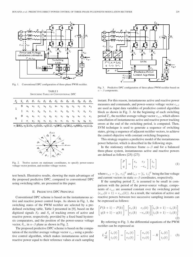
Fig. 1. Conventional DPC configuration of three-phase PWM rectifier.
TABLE ISWITCHING TABLE OF CONVENTIONAL DPC
Fig. 2. Twelve sectors on stationary coordinates, to specify power-sourcevoltage vector position, and rectifier voltage vectors.
test bench. Illustrative results, showing the main advantages ofthe proposed predictive DPC, compared to conventional DPCusing switching table, are presented in this paper.
II. PREDICTIVE DPC PRINCIPLE
Conventional DPC scheme is based on the instantaneous ac-tive and reactive power control loops. As shown in Fig. 1, theswitching states of the PWM rectifier are selected by a pre-defined switching table, Table I presented in [9], based on thedigitized signals SP and Sq of tracking errors of active andreactive power, respectively, provided by a fixed band hystere-sis comparators, and the position of the power-source voltagevector, θn , in α–β plane as shown in Fig. 2.
The proposed predictive DPC scheme is based on the compu-tation of the rectifier average voltage vector vαβ using a predic-tive control algorithm, which makes instantaneous active andreactive power equal to their reference values at each sampling
Fig. 3. Predictive DPC configuration of three-phase PWM rectifier based onα − β components.
instant. For this reason, instantaneous active and reactive powermeasures and commands, and power-source voltage vector eαβ
are used as input data variables of predictive control algorithmblock as shown in Fig. 3. At the beginning of each switchingperiod Ts , the rectifier average voltage vector vαβ , which allowscancellation of instantaneous active and reactive power trackingerrors at the end of the switching period, is computed. Then,SVM technique is used to generate a sequence of switchingstates, giving a sequence of adjacent rectifier vectors, to achievethe control objective with constant switching frequency.
This strategy requires a predictive model of the instantaneouspower behavior, which is described in the following steps.
In the stationary reference frame α–β and for a balancedthree-phase system, instantaneous active and reactive powersare defined as follows [25]–[27]:[
P
q
]=
[eα eβ
eβ −eα
][iα
iβ
](1)
where eαβ = [eα eβ ]T and iαβ = [iα iβ ]T being the line voltageand current vectors in static α–β coordinates, respectively.
If the sampling period Ts is assumed to be small in com-parison with the period of the power-source voltage, compo-nents of eαβ are assumed constant over the switching period(eαβ (k + 1) = eαβ (k)). As a result, the variation of active andreactive powers between two successive sampling instants canbe expressed as follows:[P (k + 1) − P (k)q(k + 1) − q(k)
]=
[eα (k) eβ (k)eβ (k) −eα (k)
][iα (k + 1) − iα (k)iβ (k + 1) − iβ (k)
].
(2)By referring to Fig. 3, the differential equations of the PWM
rectifier can be expressed as
Ld
dt
[iα (t)iβ (t)
]=
[eα (t)eβ (t)
]−
[vα (t)vβ (t)
]− R
[iα (t)iβ (t)
]. (3)
230 IEEE TRANSACTIONS ON POWER ELECTRONICS, VOL. 25, NO. 1, JANUARY 2010
By neglecting the influence of the resistance of reactors R andusing a discrete first order approximation of (3), the variation ofinput current vector is obtained as follows:[
iα (k + 1) − iα (k)iβ (k + 1) − iβ (k)
]=
Ts
L
([eα (k)eβ (k)
]−
[vα (k)vβ (k)
]). (4)
Substituting (4) in (2), variation of active and reactive powerduring one switching period Ts is given as follows:[
P (k + 1) − P (k)q(k + 1) − q(k)
]=
Ts
L
[eα (k) eβ (k)eβ (k) −eα (k)
]
×([
eα (k)eβ (k)
]−
[vα (k)vβ (k)
]). (5)
Since the control objective is to force active and reactivepower to be equal to their reference values at the next samplinginstant, (6) is replaced in (5)[
P (k + 1)q(k + 1)
]=
[P ∗(k + 1)q∗(k + 1)
]. (6)
By solving the obtained equation (5), the required rectifieraverage voltage vector is expressed as follows:[
vα (k)vβ (k)
]=
[eα (k)eβ (k)
]− L
Ts ‖eαβ‖2
[eα (k) eβ (k)eβ (k) −eα (k)
]
×[
P ∗(k + 1) − P (k)q∗(k + 1) − q(k)
]. (7)
whereeα , eβ power-source voltage vector components in the sta-
tionary reference frame α–β;‖eαβ‖ module of the vector eαβ ;vα , vβ ac terminal voltage vector of the PWM rectifier;Ts the switching period;P ∗, P instantaneous active power command and measure,
respectively;q∗, q instantaneous reactive power command and mea-
sure, respectively.In all DPC schemes, reactive power command q∗ is directly
given from the outside of the controller, usually equal to zero forunity power factor operation of the converter. However, the ac-tive power command P ∗ is provided from the outer proportional-integral dc-bus voltage controller. If tracking error of dc-busvoltage is assumed constant over two successive sampling peri-ods, the instantaneous active power command at the next sam-pling instant (k + 1) can be estimated using a linear extrapola-tion as shown in Fig. 4.
Active and reactive power commands at the next samplinginstant (k + 1) are given by the following equation:[
P ∗(k + 1)
q∗(k + 1)
]=
[2P ∗(k) − P ∗(k − 1)
q∗(k)
]. (8)
The digital P-DPC law under static α − β coordinates, whichprovides the required rectifier average voltage vector to be ap-plied during each switching period is given by the following
Fig. 4. Predictive value estimation of active power command.
equation:[vα (k)
vβ (k)
]=
[eα (k)
eβ (k)
]− L
Ts ‖eαβ‖2
[eα (k) eβ (k)
eβ (k) −eα (k)
]
×[
∆P ∗(k) + εP (k)
εq (k)
](9)
where εP (k) and εq (k) are the actual active and reactivepower tracking errors, respectively. ∆P ∗(k) is the actualchange in active power command given by ∆P ∗(k) = P ∗(k) −P ∗(k − 1).
On the other hand, predictive control law equation representedby (9) can be expressed in rotating reference frame d–q, usingthe following relations:[
P
q
]=
[ed eq
eq −ed
][id
iq
]. (10)
For purely sinusoidal power-source voltages ed and eq areconstant (edq (k + 1) = edq (k)). Therefore, the variation of ac-tive and reactive powers between two successive sampling in-stants can be expressed as follows:[P (k + 1) − P (k)
q(k + 1) − q(k)
]=
[ed(k) eq (k)
eq (k) −ed(k)
][id(k + 1) − id(k)
iq (k + 1) − iq (k)
].
(11)Input current equation, in rotating d–q reference frame, of
three-phase PWM rectifier is given by the following equation:
Ld
dt
[id(t)
iq (t)
]=
[ed(t)
eq (t)
]−
[vd(t)
vq (t)
]
− R
[id(t)
iq (t)
]+
[ωLiq (t)
−ωLid(t)
]. (12)
In order to decouple the previous differential equation, weassume that[
ud(t)
uq (t)
]=
[vd(t)
vq (t)
]+
[−ωLiq (t)
ωLid(t)
]. (13)
By neglecting the influence of the resistances R and replacing(13), (12) gives
Ld
dt
[id(t)
iq (t)
]=
[ed(t)
eq (t)
]−
[ud(t)
uq (t)
]. (14)
BOUAFIA et al.: PREDICTIVE DIRECT POWER CONTROL OF THREE-PHASE PULSEWIDTH MODULATION RECTIFIER 231
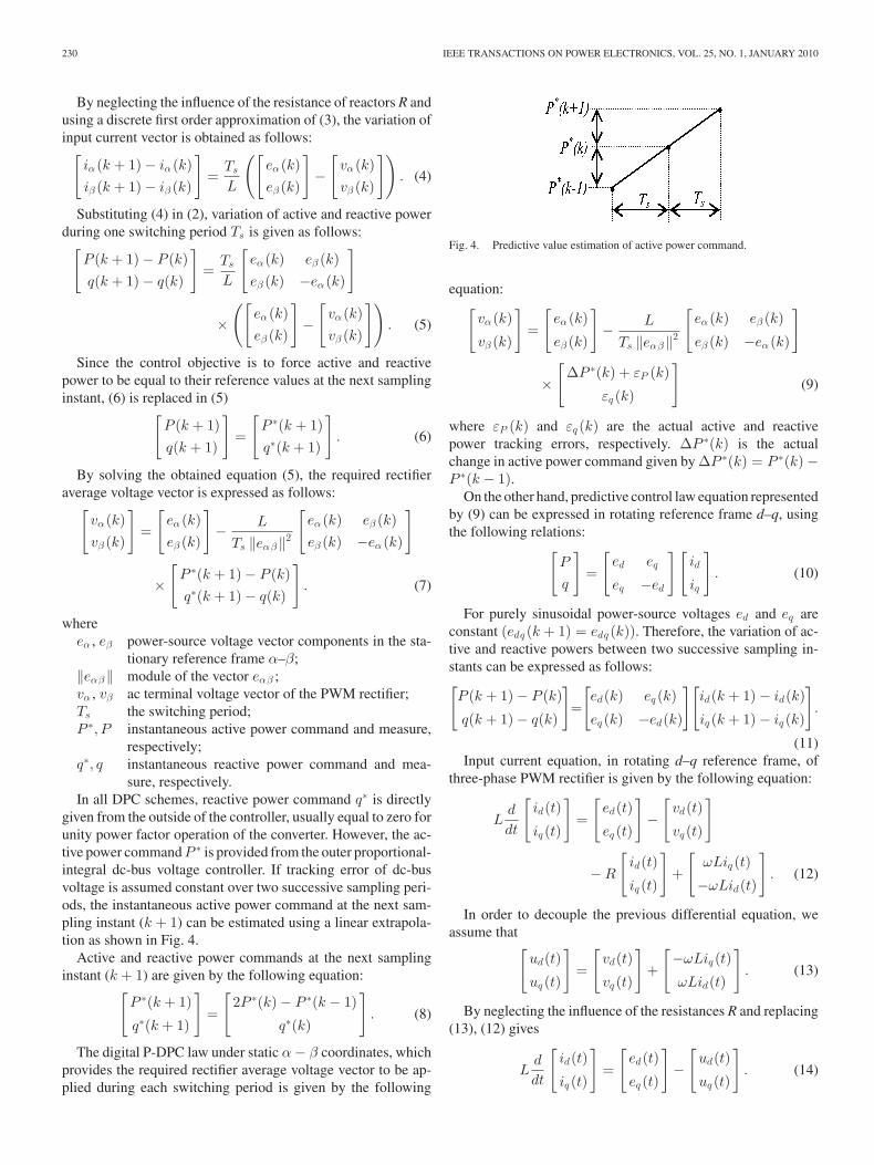
TABLE IIELECTRICAL PARAMETERS OF POWER CIRCUIT
By reproducing the same calculations as previously, we obtainthe predictive direct power control law making instantaneousactive and reactive power equal to their reference values at eachsampling instant as follows:[
ud(k)
uq (k)
]=
[ed(k)
eq (k)
]− L
Ts‖edq‖2
[ed(k) eq (k)
eq (k) −ed(k)
]
×[
∆P ∗(k) + εP (k)
εq (k)
]. (15)
The rectifier average voltage vector in the rotating referenceframe d–q is given by the following expression:[
vd(k)
vq (k)
]=
[ud(k)
uq (k)
]+
[ωLiq (k)
−ωLid(k)
]. (16)
To use the SVM, transformation from rotating d–q coordi-nates to static α − β coordinates is necessary by using the fol-lowing matrix:[
vα (k)
vβ (k)
]=
[sin(θ) cos(θ)
− cos(θ) sin(θ)
] [vd(k)
vq (k)
]. (17)
III. SIMULATION RESULTS
Both predictive DPC algorithms, (9), (15), (16), of three-phase PWM rectifier developed in this work have been sim-ulated using MATLAB/SimulinkMT tool. The main electricaland control parameters, used in simulation and implementationtests, are shown in Table II. The following simulation resultsare obtained with the proposed P-DPC and conventional one forpurely sinusoidal power-source voltages.
Simulation results in steady state obtained with both P-DPCalgorithms, based on α − β and d–q components, and conven-tional DPC using switching table are shown in Fig. 5–7, re-spectively, in which (vα , vβ ) and (vd, vq ) are the calculatedrectifier average voltage vector components obtained with pre-dictive DPC algorithm.
It can be seen from these simulation results that the proposedP-DPC is much better than DPC using switching table. Figs. 5and 6 show that instantaneous active power, instantaneous reac-tive power and dc-bus voltage track their references with goodaccuracy and stability. Input currents have nearly sinusoidalwaveforms (THD = 0.65%) and in phase with line voltages.Therefore, unity power factor operation of the converter is suc-cessfully achieved by maintaining reactive power close to zero.
Fig. 5. Simulation results in steady state for P-DPC in α − β reference framefor v∗
dc = 180 V and q∗ = 0 var, THD = 0.65%.
Both predictive DPC algorithms have the same power controlperformance in steady and transient states, except that reac-tive power value has a small offset in case of α − β referenceframe. This offset is caused by the assumption that eα and eβ
are constant over the switching period (eαβ (k + 1) = eαβ (k))taken into account in (2). However, for purely sinusoidal power-source voltages, eα and eβ have a sinusoidal form. Therefore,this assumption causes a small shift between line power-sourcevoltages and input currents. In simulation, this shift is ϕ = 1.3◦
and introduce a small offset in the reactive power. In case ofd–q reference frame and for a purely sinusoidal power-sourcevoltages, the shift between line power-source voltages and in-put currents is negligible ϕ = 0.00085◦, because ed and eq areconstant and edq (k + 1) = edq (k) for all the time.
Fig. 7 shows that input currents obtained with conventionalDPC using switching table are distorted (THD = 12.05%), be-cause instantaneous active and reactive powers are poorly con-trolled. In order to compare the performance of the proposedpredictive DPC with DPC using switching table, an enlargementon one main period for sectors of active and reactive power is

232 IEEE TRANSACTIONS ON POWER ELECTRONICS, VOL. 25, NO. 1, JANUARY 2010
Fig. 6. Simulation results in steady state for predictive DPC in d–q referenceframe for v∗
dc = 180 V and q∗ = 0 var, THD = 0.66%.
presented for P-DPC and DPC using switching table in Figs. 8and 9, respectively.
Fig. 8 shows that the proposed P-DPC ensures smooth andsimultaneous control of active and reactive power during allsectors of the main period. However, Fig. 9 shows that reactivepower is poorly controlled during even sectors (2,4,6,8,10,12)and the active power is poorly controlled during odd sectors(1,3,5,7,9,11) for conventional DPC using switching table.
Fig. 10 shows transient behavior of instantaneous activeand reactive power, dc-bus voltage and input currents incase of sudden change from uncontrolled rectifier state [ob-tained inhibiting insulated gate bipolar transistors (IGBTs)conduction and using anti-paralleling diodes] to PWM rec-tifier, operating in open loop (P ∗ is nominal (516 W) andq∗ = 0 var). After a very short transient, active power tacks itsreference with good approximation and stability, dc-bus volt-age is maintained constant, the reactive power is successfullyreduced and maintained close to zero, and input currents havenearly sinusoidal waveforms.
The predictive model of instantaneous active and reactivepower of three-phase PWM rectifier developed in this work,
Fig. 7. Simulation results in steady state for conventional DPC using switchingtable for v∗
dc = 180 V and q∗ = 0 var, THD = 12.05%.
Fig. 8. Enlargement on one main period of active and reactive power for theproposed predictive DPC.
Fig. 9. Enlargement on one main period of active and reactive power forconventional DPC using switching table.
represented by the (5), depends only on the parameter L of thecircuit. This inductance value L is assumed constant. Therefore,the obtained predictive DPC algorithms, (9) and (15), dependonly on the selected value of L, because the other variables(eα (k), eβ (k), εP (k), εq (k), and ∆P ∗(k)) are measured at ev-ery sampling instant and the switching period Ts is constant. Inorder to show the effect of error in the value of the inductance

BOUAFIA et al.: PREDICTIVE DIRECT POWER CONTROL OF THREE-PHASE PULSEWIDTH MODULATION RECTIFIER 233
Fig. 10. Transient of sudden change from uncontrolled rectifier to PWMrectifier for the proposed P-DPC for P ∗ = 516 W and q∗ = 0 var.
Fig. 11. Different parts of experimental test bench and its system control:1) PWM rectifier, 2) dSPACE I/O connectors, 3) isolating transformer, 4) inter-connecting reactance, 5) HZ64, 6) PR30.
L, on the performance of the proposed control strategy, simula-tion tests have proved that the proposed strategy keeps the samecontrol performance in steady and transient states even in caseof error of ±30% (both values 0.7*L and 1.3*L). Simulationresults in steady state for both predictive DPC algorithms aresimilar to those of Figs. 5 and 6.
IV. EXPERIMENTAL SYSTEM AND RESULTS
The developed P-DPC has been tested en a three-phase PWMrectifier. The specifications of the experimental system are asshown previously in Table II. The test bench, shown in Fig. 11,has been developed at the LAII-Laboratory, France. It consists
Fig. 12. Experimental waveforms in steady state for predictive DPC for v∗dc =
180 V and q∗ = 0 var.
of a three-phase IGBT based inverter of 20 kVA (SEMIKRON)with anti-paralleling diodes (module SKM 40 GB 121D) andthree two-channel driver (SKHI 21), which plays the role ofthe PWM rectifier. Two Hall-effect CTs LEM (PR30) and threeisolation amplifiers HAMEG (HZ64) are employed to measuretwo input currents (ia and ic ), the dc-bus voltage and two line-to-line power-source voltages (eab and eca ), respectively.
The predictive DPC algorithms run under the MATLAB/SimulinkMT environment in a dSPACE DSP system (DS1104)real-time platform inserted in a PC-Pentium. Slave DSP three-phase PWM generation block is employed to convert duty cyclesprovided by SVM to PWM signals Sa , Sb , and Sc .
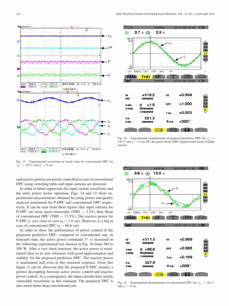
The experimental results in steady state, for both predictiveDPC algorithms in α − β and d–q reference frame, are simi-lar and showed in Fig. 12. Moreover, experimental results ofconventional DPC using switching table are showed in Fig. 13.These experimental results are very close to the previous sim-ulation results and prove the validity of the proposed P-DPC,which is much better than conventional one.
Fig. 12 shows that dc-bus voltage, instantaneous active andreactive powers are constant and very close to their references.Input currents have nearly sinusoidal waveforms and in phasewith line power-source voltages because the reactive power ismaintained close to zero. Fig. 13 shows that instantaneous active
234 IEEE TRANSACTIONS ON POWER ELECTRONICS, VOL. 25, NO. 1, JANUARY 2010
Fig. 13. Experimental waveforms in steady state for conventional DPC forv∗
dc = 180 V and q∗ = 0 var.
and reactive powers are poorly controlled in case of conventionalDPC using switching table and input currents are distorted.
In order to better appreciate the input current waveforms andthe unity power factor operation, Figs. 14 and 15 show ex-perimental measurements obtained by using power and qualityanalyzer instrument for P-DPC and conventional DPC respec-tively. It can be seen from these figures that input currents forP-DPC are more quasi-sinusoidal (THD = 2.5%) than thoseof conventional DPC (THD = 15.5%). The reactive power forP-DPC is very close to zero (q = 1.9 var). However, it is big incase of conventional DPC (q = 86.6 var).
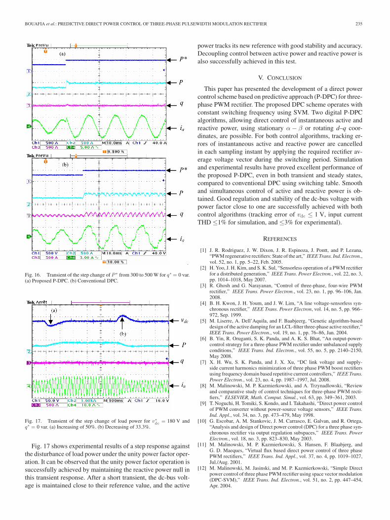
In order to show the performance of power control of theproposed predictive DPC, compared to conventional one, intransient state, the active power command P ∗ is increased inthe following experimental test showed in Fig. 16 from 300 to500 W. After a very short transient, the active power is main-tained close to its new reference with good approximation andstability for the proposed predictive DPC. The reactive poweris maintained null even in this transient response. From thisfigure, it can be observed that the proposed P-DPC ensures aperfect decoupling between active power control and reactivepower control. As a consequence, the input currents have nearlysinusoidal waveforms in this transient. The proposed DPC isalso much better than conventional one.
Fig. 14. Experimental measurements of proposed predictive DPC for v∗dc =
180 V and q∗ = 0 var, PF: the power factor, DPF: displacement factor of inputcurrent.
Fig. 15. Experimental measurements of conventional DPC for v∗dc = 180 V
and q∗ = 0 var.
BOUAFIA et al.: PREDICTIVE DIRECT POWER CONTROL OF THREE-PHASE PULSEWIDTH MODULATION RECTIFIER 235
Fig. 16. Transient of the step change of P ∗ from 300 to 500 W for q∗ = 0 var.(a) Proposed P-DPC. (b) Conventional DPC.
Fig. 17. Transient of the step change of load power for v∗dc = 180 V and
q∗ = 0 var. (a) Increasing of 50%. (b) Decreasing of 33.3%.
Fig. 17 shows experimental results of a step response againstthe disturbance of load power under the unity power factor oper-ation. It can be observed that the unity power factor operation issuccessfully achieved by maintaining the reactive power null inthis transient response. After a short transient, the dc-bus volt-age is maintained close to their reference value, and the active
power tracks its new reference with good stability and accuracy.Decoupling control between active power and reactive power isalso successfully achieved in this test.
V. CONCLUSION
This paper has presented the development of a direct powercontrol scheme based on predictive approach (P-DPC) for three-phase PWM rectifier. The proposed DPC scheme operates withconstant switching frequency using SVM. Two digital P-DPCalgorithms, allowing direct control of instantaneous active andreactive power, using stationary α − β or rotating d–q coor-dinates, are possible. For both control algorithms, tracking er-rors of instantaneous active and reactive power are cancelledin each sampling instant by applying the required rectifier av-erage voltage vector during the switching period. Simulationand experimental results have proved excellent performance ofthe proposed P-DPC, even in both transient and steady states,compared to conventional DPC using switching table. Smoothand simultaneous control of active and reactive power is ob-tained. Good regulation and stability of the dc-bus voltage withpower factor close to one are successfully achieved with bothcontrol algorithms (tracking error of vdc ≤ 1 V, input currentTHD ≤1% for simulation, and ≤3% for experimental).
REFERENCES
[1] J. R. Rodriguez, J. W. Dixon, J. R. Espinoza, J. Pontt, and P. Lezana,“PWM regenerative rectifiers: State of the art,” IEEE Trans. Ind. Electron.,vol. 52, no. 1, pp. 5–22, Feb. 2005.
[2] H. Yoo, J. H. Kim, and S. K. Sul, “Sensorless operation of a PWM rectifierfor a distributed generation,” IEEE Trans. Power Electron., vol. 22, no. 3,pp. 1014–1018, May 2007.
[3] R. Ghosh and G. Narayanan, “Control of three-phase, four-wire PWMrectifier,” IEEE Trans. Power Electron., vol. 23, no. 1, pp. 96–106, Jan.2008.
[4] B. H. Kwon, J. H. Youm, and J. W. Lim, “A line voltage-sensorless syn-chronous rectifier,” IEEE Trans. Power Electron, vol. 14, no. 5, pp. 966–972, Sep. 1999.
[5] M. Liserre, A. Dell’Aquila, and F. Baabjeerg, “Genetic algorithm-baseddesign of the active damping for an LCL-filter three-phase active rectifier,”IEEE Trans. Power Electron., vol. 19, no. 1, pp. 76–86, Jan. 2004.
[6] B. Yin, R. Oruganti, S. K. Panda, and A. K. S. Bhat, “An output-power-control strategy for a three-phase PWM rectifier under unbalanced supplyconditions,” IEEE Trans. Ind. Electron., vol. 55, no. 5, pp. 2140–2150,May 2008.
[7] X. H. Wu, S. K. Panda, and J. X. Xu, “DC link voltage and supply-side current harmonics minimization of three phase PWM boost rectifiersusing frequency domain based repetitive current controllers,” IEEE Trans.Power Electron., vol. 23, no. 4, pp. 1987–1997, Jul. 2008.
[8] M. Malinowski, M. P. Kazmierkowski, and A. Trzynadlowski, “Reviewand comparative study of control techniques for three-phase PWM recti-fiers,” ELSEVIER, Math. Comput. Simul., vol. 63, pp. 349–361, 2003.
[9] T. Noguchi, H. Tomiki, S. Kondo, and I. Takahashi, “Direct power controlof PWM converter without power-source voltage sensors,” IEEE Trans.Ind. Appl., vol. 34, no. 3, pp. 473–479, May 1998.
[10] G. Escobar, A. M. Stankovic, J. M. Carrasco, E. Galvan, and R. Ortega,“Analysis and design of Direct power control (DPC) for a three phase syn-chronous rectifier via output regulation subspaces,” IEEE Trans. PowerElectron., vol. 18, no. 3, pp. 823–830, May 2003.
[11] M. Malinowski, M. P. Kazmierkowski, S. Hansen, F. Blaabjerg, andG. D. Maeques, “Virtual flux based direct power control of three phasePWM rectifiers,” IEEE Trans. Ind. Appl., vol. 37, no. 4, pp. 1019–1027,Jul./Aug. 2001.
[12] M. Malinowski, M. Jasinski, and M. P. Kazmierkowski, “Simple Directpower control of three phase PWM rectifier using space vector modulation(DPC-SVM),” IEEE Trans. Ind. Electron., vol. 51, no. 2, pp. 447–454,Apr. 2004.

236 IEEE TRANSACTIONS ON POWER ELECTRONICS, VOL. 25, NO. 1, JANUARY 2010
[13] M. Cichowlas, M. Malinowski, M. P. Kazmierkowski, D. L. Sobczuk, andJ. Pou, “Active filtering function of three-phase PWM boost rectifier underdifferent line voltage conditions,” IEEE Trans. Ind. Electron., vol. 52,no. 2, pp. 410–419, Apr. 2005.
[14] L. A. Serpa, S. Ponnaluri, P. M. Barbosa, and J. W. Kolar, “A modifieddirect power control strategy allowing the connection of three-phase in-verters to the grid through LCL filters,” IEEE Trans. Ind. Appl., vol. 43,no. 5, pp. 1388–1400, Sep./Oct. 2007.
[15] S. Vazquez, J. A. Sanchez, J. M. Carrasco, J. I. Leon, and E. Galvan,“A model-based direct power control for three-phase power converters,”IEEE Trans. Ind. Electron., vol. 55, no. 4, pp. 1647–11657, Apr. 2008.
[16] D. S. Martin, J. L. Rodriguez, and S. Arnalte, “Direct power controlapplied to doubly fed induction generator under unbalanced grid voltageconditions,” IEEE Trans. Power Electron., vol. 23, no. 5, pp. 2328–2336,Sep. 2008.
[17] B. S. Chen and G. Joos, “Direct power control of active filters with av-eraged switching frequency regulation,” IEEE Trans. Power Electron.,vol. 23, no. 6, pp. 2729–2737, Nov. 2008.
[18] S. A. Larrinaga, M. A. R. Vidal, E. Oyarbide, and J. R. T. Apraiz, “Pre-dictive control strategy of DC/AC converters based on direct power con-trol,” IEEE Trans. Ind. Electron., vol. 54, no. 3, pp. 1261–1271, Jun.2007.
[19] P. Cortes, J. Rodrıguez, D. E. Quevedo, and C. Silva, “Predictive currentcontrol strategy with imposed load current spectrum,” IEEE Trans. PowerElectron., vol. 23, no. 2, pp. 612–618, Mar. 2008.
[20] P. Cortes, J. Rodrıguez, P. Antoniewicz, and M. P. Kazmierkowski, “Directpower control of an AFE using predictive control,” IEEE Trans. PowerElectron., vol. 23, no. 5, pp. 2516–2523, Sep. 2008.
[21] L. Malesani, P. Mattavelli, and S. Buso, “Robust dead-beat current controlfor PWM rectifiers and active filters,” IEEE Trans. Ind. Appl., vol. 35,no. 3, pp. 613–620, May/Jun. 1999.
[22] R. Ottersten and J. Svensson, “Vector current controlled voltage sourceconverter-deadbeat control and saturation strategies,” IEEE Trans. PowerElectron., vol. 17, no. 2, pp. 279–285, Mar. 2002.
[23] P. Mattavelli, “An improved deadbeat control for UPS using disturbanceobservers,” IEEE Trans. Ind. Electron., vol. 52, no. 1, pp. 206–212, Feb.2005.
[24] and Y. A. I. Mohamed and E. F. El-Saadany, “Adaptive discrete-time grid-voltage sensorless interfacing scheme for grid-connected DG-invertersbased on neural-network identification and deadbeat current regula-tion,” IEEE Trans. Power Electron., vol. 23, no. 1, pp. 308–321, Jan.2008.
[25] R. S. Herrera, P. Salmeron, and H. Kim, “Instantaneous reactive powertheory applied to active power filter compensation: Different approaches,assessment, and experimental results,” IEEE Trans. Ind. Electron., vol. 55,no. 1, pp. 184–196, Jan. 2008.
[26] G. Superti and G. Todeschini, “Discussion on instantaneous p-q strategiesfor control of active filters,” IEEE Trans. Power Electron., vol. 23, no. 4,pp. 1945–1955, Jul. 2008.
[27] X. H. Wu, S. K. Panda, and J. X. Xu, “Analysis of the instantaneous powerflow for three-phase PWM boost rectifier under unbalanced supply voltageconditions,” IEEE Trans. Power Electron., vol. 23, no. 4, pp. 1679–1691,Jul. 2008.
Abdelouahab Bouafia was born in Algeria on March1, 1971. He received the Engineering degree from theUniversity of Annaba, Annaba, Algeria, in 1997, andthe Master degree from the University of Setif, Setif,in 2001, both in electrical engineering. He is currentlyworking toward the Ph.D. degree at the Laboratoryof Power Electronics and Industrial Electronics, De-partment of Electronics, University of Setif.
His research interests include modeling and con-trol of power converters, fuzzy logic control, and pre-dictive control applied to power electronics systems
such as PWM rectifiers.
Jean-Paul Gaubert (M’09) was born in France onJune 30th, 1965. He received the Engineering de-gree from the University of Science and Technol-ogy of Clermont-Ferrand, Clermont-Ferrand, France,in 1988, the Master degree in 1990, and the Ph.D.degree in 1992 from the University of Scienceand Technology of Lille, Lille, all in electricalengineering.
He is currently an Assistant Professor at theDepartment of Electrical and Electronics Engineer-ing, Institute of Technology, University of Poitiers,
Poitiers, France. His current research interests, with the electrical engineeringand control team of the Laboratory of Automatic and Industrial Data, are mod-eling and advanced control of power converters and power electronics systemsand their digital control techniques with real time implementation. The derivedtopics deal with power quality such as active power filters, PWM rectifiers, re-newable energy systems, and electric vehicles. A further main area of researchis development of new converters topologies such as quadratic converters.
Dr. Gaubert is a member of the EPE Association.
Fateh Krim (M’02–SM’02) received the B.Sc. de-gree from Claude Bernard University, Lyon, France,in 1976, the M.Sc. and the Engineer degrees in elec-trical engineering from the Ecole Centrale, Lyon,in 1979, the Ph.D. degree from the PolytechnicNational Institute, Grenoble, and the special doc-torate degree in industrial control from the Uni-versity of Setif, Setif, Algeria, in 1982 and 1996,respectively.
From 1982 to 1985, he was the Head of theIntegrated Circuit Design Department, CIT-Alcatel,
Paris. He is currently a Professor of electrical engineering, and Director ofthe Laboratory of Power Electronics and Industrial Electronics, Departmentof Electronics, University of Setif. His research interests include systemscontrol, power, industrial electronics, and renewable energies. He is the au-thor of more than 80 papers in international journals and refereed conferenceproceedings.
Dr. Krim is a Member of the IEEE Power Electronics Society, the IEEEComputational Intelligence Society, the IEEE Industrial Electronics Society,and the IEEE Power Engineering Society.

本文献由“学霸图书馆-文献云下载”收集自网络,仅供学习交流使用。
学霸图书馆(www.xuebalib.com)是一个“整合众多图书馆数据库资源,
提供一站式文献检索和下载服务”的24 小时在线不限IP
图书馆。
图书馆致力于便利、促进学习与科研,提供最强文献下载服务。
图书馆导航:
图书馆首页 文献云下载 图书馆入口 外文数据库大全 疑难文献辅助工具


![Predictive Vector Selector for Direct Torque Control of ...Direct Torque Control using Matrix Converters are shown. I. INTRODUCTION Direct Torque Control (DTC) [1] and Direct Self](https://img.pdfslide.net/doc/110x75/5f70317e3425cd0d4608358b/predictive-vector-selector-for-direct-torque-control-of-direct-torque-control.jpg)