Embed Size (px)
Citation preview
Predictive Maintenance Framework
for a Vehicular IoT Gateway Node
Using Active Database Rules
by
Sergei Butylin
Thesis submitted to the
Faculty of Graduate and Postdoctoral Studies
In partial fulfillment of the requirements
For the M.Sc. degree in
Computer Science
School of Electrical Engineering and Computer Science
Faculty of Graduate Studies
University of Ottawa
c© Sergei Butylin, Ottawa, Canada, 2018

Abstract
This thesis describes a proposed design and implementation of a predictive maintenance
engine developed to fulfill the requirements of the STO Company (Societe de transport de
l’Outaouais) for maintaining vehicles in the fleet. Predictive maintenance is proven to be
an effective approach and has become an industry standard in many fields. However, in
the transportation industry, it is still in the stages of development due to the complexity
of moving systems and the high level dimensions of involved parameters. Because it is
almost impossible to cover all use cases of the vehicle operational process using one par-
ticular approach to predictive maintenance, in our work we take a systematic approach
to designing a predictive maintenance system in several steps. Each step is implemented
at the corresponding development stage based on the available data accumulated during
system funtioning cycle.
This thesis delves into the process of designing the general infrastructural model of
the fleet management system (FMS), while focusing on the edge gateway module located
on the vehicle and its function of detecting maintenance events based on current vehicle
status. Several approaches may be used to detect maintenance events, such as a machine
learning approach or an expert system-based approach. While the final version of fleet
management system will use a hybrid approach, in this thesis paper we chose to focus
on the second option based on expert knowledge, while machine learning has been left
for future implementation since it requires extensive training data to be gathered prior to
conducting experiments and actualizing operations.
Inspired by the IDEA methodology which promotes mapping business rules as software
classes and using the object-relational model for mapping objects to database entities,
we take active database features as a base for developing a rule engine implementation.
However, in contrast to the IDEA methodology which seeks to describe the specific system
and its sub-modules, then build active rules based on the interaction between sub-systems,
we are not aware of the functional structure of the vehicle due to its complexity. Instead,
we develop a framework for creating specific active rules based on abstract classifications
structured as ECA rules (event-condition-action), but with some expansions made due
ii

to the specifics of vehicle maintenance. The thesis describes an attempt to implement
such a framework, and particularly the rule engine module, using active database features
making it possible to encapsulate the active behaviour inside the database and decouple
event detection from other functionalities. We provide the system with a set of example
rules and then conduct a series of experiments analyzing the system for performance and
correctness of events detection.
Keywords: predictive maintenance, rule engine, active databases, active rules
iii

Acknowledgements
Foremost, I would like to thank my thesis supervisors, Dr. Iluju Kiringa and Dr. Tet
Yeap for their continuous support of my masters study and research and for their patience,
motivation, enthusiasm, and immense knowledge. Their guidance helped me throughout
the period of researching and writing this thesis.
I would also like to thank my colleagues from the IoT Research group who were involved
in the STO project for their wonderful collaboration. They supported me greatly and were
always willing to help!
Finally, I must express my very sincere gratitude to my parents and, of course, to my
wife and daughter who provided me with constant support and continuous encouragement
throughout my years of study and through the process of researching and writing this
thesis. This work would not have been possible without their support.
iv

Table of Contents
List of Tables ix
List of Figures x
Nomenclature xii
1 Introduction 1
1.1 Motivation . . . . . . . . . . . . . . . . . . . . . . . . . . . . . . . . . . . . 1
1.2 Problem statement . . . . . . . . . . . . . . . . . . . . . . . . . . . . . . . 3
1.3 Proposed solution . . . . . . . . . . . . . . . . . . . . . . . . . . . . . . . . 5
1.4 Methodology . . . . . . . . . . . . . . . . . . . . . . . . . . . . . . . . . . 6
1.5 Contributions . . . . . . . . . . . . . . . . . . . . . . . . . . . . . . . . . . 6
1.6 Outline . . . . . . . . . . . . . . . . . . . . . . . . . . . . . . . . . . . . . . 7
2 Background and related work 9
2.1 Maintenance in fleet management systems . . . . . . . . . . . . . . . . . . 9
2.2 Predictive maintenance . . . . . . . . . . . . . . . . . . . . . . . . . . . . . 13
2.3 Gateway devices for vehicle monitoring . . . . . . . . . . . . . . . . . . . . 20
2.4 Vehicle sensor networks and data-protocols . . . . . . . . . . . . . . . . . . 21
v
2.5 Implementation of Rule-Engines using Active Database features and Active
Rules . . . . . . . . . . . . . . . . . . . . . . . . . . . . . . . . . . . . . . . 23
2.5.1 Idea of active rules . . . . . . . . . . . . . . . . . . . . . . . . . . . 24
2.5.2 Designing database applications with active rules . . . . . . . . . . 28
3 Architecture of a cyber-physical system for predictive maintenance 29
3.1 Conceptual scheme of the cyber-physical system . . . . . . . . . . . . . . . 29
3.2 Modelling Cyber-Physical Systems with UML, SysML, and MARTE . . . . 32
3.2.1 Problem statement . . . . . . . . . . . . . . . . . . . . . . . . . . . 32
3.2.2 Structural Modeling . . . . . . . . . . . . . . . . . . . . . . . . . . 34
3.2.3 Use Case Modeling . . . . . . . . . . . . . . . . . . . . . . . . . . . 36
3.2.4 Dynamic State Machine Modeling . . . . . . . . . . . . . . . . . . . 41
3.2.5 Dynamic Interaction Modeling . . . . . . . . . . . . . . . . . . . . . 45
3.2.6 Object and Class Structuring . . . . . . . . . . . . . . . . . . . . . 46
3.2.7 System Configuration and Deployment . . . . . . . . . . . . . . . . 48
3.2.8 Design Analysis . . . . . . . . . . . . . . . . . . . . . . . . . . . . . 48
3.2.9 Results of the modeling . . . . . . . . . . . . . . . . . . . . . . . . 49
3.3 Vehicle node: gateway hardware . . . . . . . . . . . . . . . . . . . . . . . . 50
3.4 Architecture of the Gateway Module . . . . . . . . . . . . . . . . . . . . . 52
3.4.1 Analysis of the requirements . . . . . . . . . . . . . . . . . . . . . . 52
3.4.2 Introducing the architecture . . . . . . . . . . . . . . . . . . . . . . 54
4 Implementation of the Rule Engine using Active Database features 59
4.1 IDEA methodology representation of predictive maintenance rule engine . 59
4.1.1 Types . . . . . . . . . . . . . . . . . . . . . . . . . . . . . . . . . . 60
vi
4.1.2 Classes . . . . . . . . . . . . . . . . . . . . . . . . . . . . . . . . . . 60
4.1.3 Events . . . . . . . . . . . . . . . . . . . . . . . . . . . . . . . . . . 62
4.1.4 Constraint repair triggers . . . . . . . . . . . . . . . . . . . . . . . 63
4.1.5 Business rules . . . . . . . . . . . . . . . . . . . . . . . . . . . . . . 63
4.2 Designing abstract rule definitions . . . . . . . . . . . . . . . . . . . . . . . 64
4.2.1 Example maintenance rules . . . . . . . . . . . . . . . . . . . . . . 64
4.2.2 Structuring maintenance rules . . . . . . . . . . . . . . . . . . . . . 65
4.2.3 Mapping rules to software classes . . . . . . . . . . . . . . . . . . . 71
4.3 Designing the database scheme for Active Rules representation . . . . . . . 71
4.3.1 Storing dynamic data . . . . . . . . . . . . . . . . . . . . . . . . . . 71
4.3.2 Storing rule meta-data . . . . . . . . . . . . . . . . . . . . . . . . . 72
4.4 Mapping rule classes to active database entities . . . . . . . . . . . . . . . 75
4.4.1 Mapping rule meta-data . . . . . . . . . . . . . . . . . . . . . . . . 76
4.4.2 Mapping conditions . . . . . . . . . . . . . . . . . . . . . . . . . . . 77
4.5 Challenges of using active rules for rule-engine development . . . . . . . . . 80
4.5.1 Rule termination . . . . . . . . . . . . . . . . . . . . . . . . . . . . 81
4.5.2 Rule confluence . . . . . . . . . . . . . . . . . . . . . . . . . . . . . 82
4.5.3 State consistency . . . . . . . . . . . . . . . . . . . . . . . . . . . . 83
4.5.4 Concurrent rule processing . . . . . . . . . . . . . . . . . . . . . . . 84
4.5.5 Recovering database after vehicle repair event . . . . . . . . . . . . 84
5 Experiments 86
5.1 Configuration and methodology . . . . . . . . . . . . . . . . . . . . . . . . 86
5.2 Experimental data-set . . . . . . . . . . . . . . . . . . . . . . . . . . . . . 87
5.3 Rule execution steps . . . . . . . . . . . . . . . . . . . . . . . . . . . . . . 88
vii

5.3.1 Detailed explanation of rule execution . . . . . . . . . . . . . . . . 88
5.3.2 Overview of execution steps of other example rules . . . . . . . . . 92
5.4 Performance evaluation . . . . . . . . . . . . . . . . . . . . . . . . . . . . . 94
5.4.1 Rule classes comparison (30 rules) . . . . . . . . . . . . . . . . . . . 94
5.4.2 Mixed class rule set (5 rules) . . . . . . . . . . . . . . . . . . . . . . 94
5.4.3 Mixed class rule set (25 rules) . . . . . . . . . . . . . . . . . . . . . 97
5.4.4 Mixed class rule set (55 rules) . . . . . . . . . . . . . . . . . . . . . 97
5.4.5 Mixed class rule set (85 rules) . . . . . . . . . . . . . . . . . . . . . 98
6 Conclusion and Future work 99
6.1 Conclusion . . . . . . . . . . . . . . . . . . . . . . . . . . . . . . . . . . . . 99
6.2 Directions for future work . . . . . . . . . . . . . . . . . . . . . . . . . . . 101
APPENDICES 102
A Source code of rule structure implementation 103
B SQL representation of example rules used in the thesis work 106
B.1 Example Rule 1 . . . . . . . . . . . . . . . . . . . . . . . . . . . . . . . . . 106
B.2 Example Rule 2 . . . . . . . . . . . . . . . . . . . . . . . . . . . . . . . . . 107
B.3 Example Rule 3 . . . . . . . . . . . . . . . . . . . . . . . . . . . . . . . . . 109
B.4 Example Rule 4 . . . . . . . . . . . . . . . . . . . . . . . . . . . . . . . . . 110
B.5 Example Rule 5 . . . . . . . . . . . . . . . . . . . . . . . . . . . . . . . . . 113
References 115
viii

List of Tables
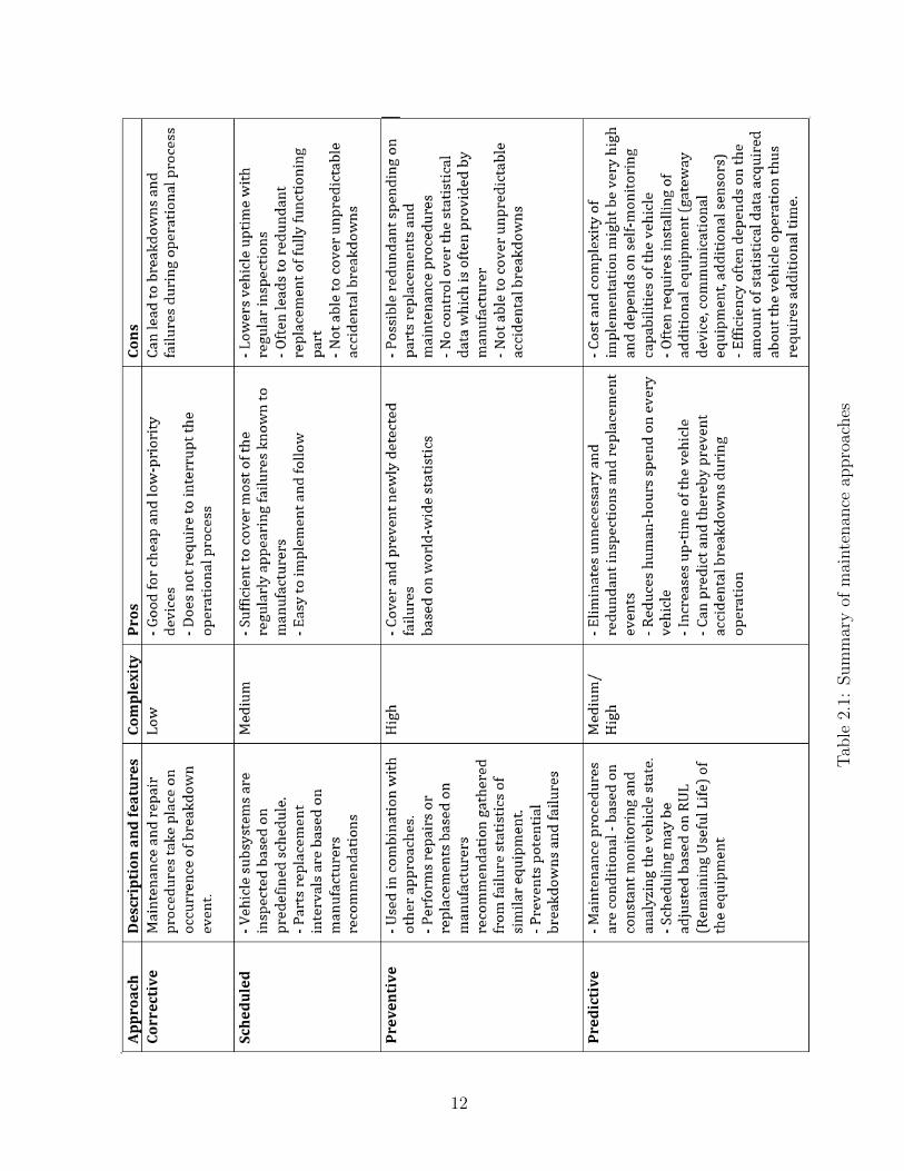
2.1 Summary of maintenance approaches . . . . . . . . . . . . . . . . . . . . . 12
3.1 Requirements for hardware of the Vehicle Node Gateway . . . . . . . . . . 51
3.2 Unit configuration of Vehicle Node gateway . . . . . . . . . . . . . . . . . 52
ix

List of Figures
2.1 Structure of j1939 packet . . . . . . . . . . . . . . . . . . . . . . . . . . . . 23
2.2 The context of rules processing . . . . . . . . . . . . . . . . . . . . . . . . 26
2.3 Steps of rules processing . . . . . . . . . . . . . . . . . . . . . . . . . . . . 26
2.4 Active rule system architecture . . . . . . . . . . . . . . . . . . . . . . . . 27
3.1 Conceptual architecture of the proposed Fleet Management System . . . . 31
3.2 Conceptual Structural Model of Problem Domain . . . . . . . . . . . . . . 35
3.3 System Context Model . . . . . . . . . . . . . . . . . . . . . . . . . . . . . 36
3.4 Software System Context Model . . . . . . . . . . . . . . . . . . . . . . . . 37
3.5 Use case model for Vehicle Node system . . . . . . . . . . . . . . . . . . . 38
3.6 State Machine for Vehicle Node system: top-level state machine . . . . . . 42
3.7 Decomposition of main operational sequence state machine . . . . . . . . . 43
3.8 Dynamic interaction model for Connecting Vehicle Node to Cloud Infras-
tructure event . . . . . . . . . . . . . . . . . . . . . . . . . . . . . . . . . . 46
3.9 Dynamic interaction modeling for Detecting events . . . . . . . . . . . . . 47
3.10 Software classes in Vehicle Node System . . . . . . . . . . . . . . . . . . . 56
3.11 Contents of the Vehicle Node Gateway based on Raspberry Pi . . . . . . . 57
3.12 General Architecture of Rule Engine Framework . . . . . . . . . . . . . . . 58
4.1 UML-definition of abstract rule structure . . . . . . . . . . . . . . . . . . . 69
x
4.2 Database tables for sensor data streams information . . . . . . . . . . . . . 73
4.3 Database tables for events data streams information . . . . . . . . . . . . . 74
4.4 Tables for storing Rule meta object . . . . . . . . . . . . . . . . . . . . . . 75
4.5 Triggering graph representing set of rules with non terminating behaviour . 82
4.6 States transitions depending on rules execution order . . . . . . . . . . . . 83
5.1 Rule triggering time-line for experimental data-set . . . . . . . . . . . . . . 95
5.2 Average execution time depending on the condition class . . . . . . . . . . 96
5.3 Execution time for 5 example rules . . . . . . . . . . . . . . . . . . . . . . 96
5.4 Execution time for 25 rules of mixed classes . . . . . . . . . . . . . . . . . 97
5.5 Execution time for 55 rules of mixed classes . . . . . . . . . . . . . . . . . 97
5.6 Execution time for 85 rules of mixed classes . . . . . . . . . . . . . . . . . 98
xi

Nomenclature
API Application program interface
CAN Controller area network
DBMS Database Management System
DFS Depth first search
DTC Diagnostic trouble code
FMS Fleet Management System
IoT Internet of Things
OBD On-board diagnostics
PDU Protocol data units
RN Root node
RPM Revolutions Per Minute
SAE Society of Automotive Engineers
SLN Server leader node
SPC Statistical process control
UI User Interface
VN Vehicle node
xii
Chapter 1
Introduction
This thesis proposes a solution for predictive maintenance issues related to the fleet manage-
ment system of transportation vehicles. The proposed solution is based on the conditional
maintenance approach with the application of active database features as an implementa-
tion for the rule-engine, which is located on the gateway device.
1.1 Motivation
Public transportation systems play a huge role in the infrastructure of modern cities.
Transport companies seek new ways to get ahead of the competition, and increasingly,
such companies are using sophisticated software applications to control and monitor their
fleet of vehicles. This software is referred as the Fleet Management System (FMS). FMS
often contains several modules which are focused on different aspects of fleet utilization
such as route planning, fuel consumption control and automating of paper work. Delegating
such functionally of FMS to automated system reduces the time-cost of daily routine and
decreases the overall cost of fleet management.
Maintenance planning is another major routine which is handled by the FMS. This is
a crucial function because it controls one of the most important parameters in commercial
vehicle utilization - uptime of the vehicle. The FMS helps to keep track of maintenance
1
events, saves repair history and facilitates planning of future maintenance based on man-
ufacturer recommendations. However, traditional maintenance planning is not always the
most efficient solution because it often leads to redundant technical inspections and the
need to interrupt vehicle operation unnecessarily. Manufacturer recommendations for spare
components always rely on the time factor rather than the state of the components. In this
situation, maintenance happens earlier than needed or, conversely, when a component that
has been worn out before the expiry date causes a break down. Despite such drawbacks, a
scheduled maintenance approach is widely used in the automotive industry and considered
to be a standard practice.
Another relevant approach is reactive maintenance or corrective maintenance. In this
approach, vehicle equipment is inspected and exchanged after a breakdown event. This
approach may lead to some potentially dangerous situations, down-times or the complete
loss of vehicles. This approach is typically used for components that have backup units or
for non-critical components in which breakdown will not affect operation of the vehicle.
Ideally, the transportation industry requires a combined approach where technicians
can inspect vehicle equipment only when it demonstrates some hidden symptoms of up-
coming breakdown or signs of being in a critical state. This approach is called predictive
maintenance and is based on constant monitor and analysis of newly obtained vehicle
data by comparing it with the observation of vehicle behaviour from the past. In com-
bination with known patterns of pre-failure states system is able to make maintenance
predictions. As a result, predictive maintenance systems notifies corresponding staff about
possible breakdowns or situations when changing of service liquids is required in advance.
This saves on the cost and effort of redundant technical inspections and prevents the full
breakdown of a vehicle, thus greatly reducing idle times of fleet vehicles.
Nowadays, most modern heavy machinery as well as transportation vehicles are equipped
with huge sensor networks driven by standard industry protocols such as SAE J1939, which
is the Society of Automotive Engineers standard recommended practice used in vehicles
for communication and diagnostics among vehicle components. During operation, vehicles
produce a vast amount of raw data such as speed, emission, distance, resource usage, driv-
2
ing behavior, and fuel consumption. Sensor networks are designed to collect this data and
be able to attach it to J1939-data streams for future analysis by technicians of automated
software.
The majority of transportation companies today do not fully benefit from utilizing
sensor data retrieved from the J1939 bus. In most cases, technicians download vehicle
data during scheduled maintenance events by connecting external devices which support
J1939 protocol. Often technicians conduct manual analysis over obtained data and make
decisions based on their experience and knowledge. This approach might be suitable for
small companies having a number of operating vehicles less than 50, but at enterprise level
when the number of vehicles exceeds 100, maintenance using manual labour becomes too
expensive since it involves extensive human resources and is ineffective because most of
the maintenance procedures are repetitive and could easily benefit from being automated.
However, this task is not trivial and even major transportation companies and vehicle
manufacturers do not implement full-cycle predictive maintenance in their commercial
products.
1.2 Problem statement
Vehicle diagnostics is a complex process which requires a lot of input data, observations
and expert knowledge. However, predictive maintenance introduces even bigger challenges
because decisions that are expected from the system are made based on real-time data
retrieved from the observation of vehicles and external factors in combination with domain
knowledge which is represented as a set of rules and analytic algorithms. Therefore, to
create a predictive analytics solution we need to handle to sub-problems:
1. Create analytics engine by first acquiring knowledge from domain experts and then
integrating this knowledge into an active system that is able to behave as human
expert by making maintenance decisions based on known states of the vehicle and
external environmental factors.
3
2. Capture observation data of both internal and external systems which influence op-
erational processes. Such factors could be classified as follows:
• Internal factors: vehicle sensor data (i.e. OBDII/J1939 data, GPS location),
wearing factor of spare parts and other data that represents internal state of
the vehicle.
• External factors: weather conditions, light conditions, road surface conditions,
traffic condition and other factors that represent the state of external systems
with which our vehicle is interacting during the operational process.
Looking at the requirements for the system, we can project previously explained sub-
problems onto our domain and formulate specific problem statements.
For the knowledge acquisition stage, we need to communicate with domain experts who
in our case are STO technicians. They share the procedures that are used each time the
maintenance process is taking place. These procedures are captured as a set of standardized
rules describing how combinations of particular indicators (i.e. engine coolant temperature
+ season + engine RPM) lead to a particular maintenance decision - i.e. check air filter.
The next stage contains several steps. It starts with choosing the manner in which
the necessary data can be acquired. This should be a device that could be installed in
the vehicle and connected to the sensor network and vehicle power supply. At the same
time, it should be able to operate from the vehicle separately as an autonomous unit. The
primary purpose of this device is to capture all the data coming from internal (vehicle)
and external (environment) systems, store incoming raw data in the local storage and
stream data to the cloud server infrastructure. The subsequent part of this stage of the
problem is the most complex and involves creating a framework for converting domain
knowledge into an automated expert system. This systems purpose is to continuously
analyze the incoming data using rule-engine based on expert knowledge, and to make final
decisions about possible breakdowns or other health issues of the vehicle. Developing such
a framework is the main problem stated in this thesis. It involves research of the field,
analyzing example rules acquired from domain experts, designing and developing rules
classes and creating a framework that implements the required functionality.
4

It should be mentioned that stated problem does not include situations when sensors of
the vehicle could fail, thereby, deliver wrong readings into the system. We do not have any
mechanisms to identify faulty sensors at the moment, thus, assume that all the information
provided by sensor network is valid.
1.3 Proposed solution
We divide the solution for the stated problems into two sections. First, we solve the
problem of data acquisition, data saving and data streaming by designing and modeling the
architecture for the proposed predictive maintenance system. This is done using industry
standard tools like UML with SysML and MARTE extensions. We also extend models with
some custom annotations. For the solution to the second sub-problem, which is analyzing
vehicle data and making a maintenance diagnosis prediction, we stick with the rule-engine
approach based on active database features. This approach gives us the capability to
decouple event detection functionality from other modules and encapsulate it inside the
database management system of the gateway device. At the same time, because the data
from vehicle sensor network is streamed into local database storage, we can analyze sensor
data ”on the fly” inside database by utilizing active database features without creating
another software layer for it.
However, managing active database entities such as triggers and stored procedures is
very difficult and needs systematization to be utilized effectively. For this purpose, we
develop the framework for creating and managing active rules. This strategy is inspired by
the IDEA -methodology [8], which stores active rules as user-defined software classes writ-
ten using Chimera language [21], which could be mapped to database entities. We create
our own classification of rules and let users of the system input new rules by constructing
them from components based on presented classifications.
5
1.4 Methodology
Methodology presented in the thesis in based on both software engineering and knowledge
engineering principles. The entire predictive maintenance system for the FMS is built
in several steps. Each step depends on the amount of historical data gathered about the
behaviour of the vehicles in the fleet. Since the FMS project is now in its early development
stage, this thesis is focused on the predictive maintenance approach based on a rule engine
which uses the knowledge base acquired from human experts and technical documentation
about the vehicle. We conducted a series of interviews with STO technicians responsible
for maintenance routines. Following the interview, we constructed a set of rules based on
the acquired knowledge which utilized available data coming from the J1939-protocol. The
resulting set of rules had to be transported into the expert system for the gateway. The
framework for converting maintenance business rules into ECA-rules for an active database
system was developed to implement this task. Assuming that the knowledge base should
be expended without help from database experts, the UI-module should allow to input
new rules into the system. The architecture of the gateway module was designed and
implemented on the Raspberry Pi computer [43]. It includes the modules for interaction
with external systems such as Cloud Infrastructure and sensor network (vehicle J1939 and
external sensors). The gateway device was tested at the STO site with a Volvo bus for the
ability to gather and process vehicle data. The implemented gateway software is expected
to proceed with real-time data coming from the sensor network and, derive events for the
rule engine. Based on the rules implemented in the rule engine, maintenance decisions are
made which comprise the final step in the process of predictive maintenance.
1.5 Contributions
The main contribution of the thesis is the development and integration of predictive main-
tenance mechanism for a FMS, embedded in the rule engine of the gateway device. This
work contributes to this process by firstly modeling the required behaviour and structure
of the overall fleet management system and, secondly, introducing the implementation of
6
rule engine using active features of the MySQL database management system. The model-
ing phase is completed using the SysML and MARTE methodologies for the cyber-physical
systems described in [24][45]. During the modeling process, some extensions of the method-
ology were introduced that are applicable specifically to vehicle monitoring use case. This
has been done to clarify how rule engine would be integrated in the overall system and
the to show the interactions between components. The rule engine development phase is
a larger contribution brought forth in this thesis and consists of a proposed approach for
mapping business rules as software objects and then as database entities. To achieve this,
we needed to classify maintenance business rules and their its components to provide max-
imum capabilities for the developers and users that are going to be creating and entering
new rules into the system. All these steps together form a framework that lets users of
the system (domain experts, maintenance technicians) input new rules using predefined
templates that represent different classes of rules and its components such as events, con-
ditions and resulting actions. To summarize, the steps that has been taken towards the
solution are as follows:
• Propose architecture of a predictive maintenance system for the FMS.
• Build model of proposed architecture using UML standards and extend the annota-
tions for specific use-case of vehicle health monitoring.
• Use active database features to implement active rules for predictive maintenance
system.
• Design and develop the framework for generating active rules from user input. This
involves developing a classification of rules and their components.
1.6 Outline
The remaining part of the thesis is organized as follows. In Chapter 2, we conduct research
in the field and present a survey of the recent work that has been done in the area of
predictive analytics and, predictive maintenance for fleet management systems. We then
7

summarize the current state of the market of edge analytics, including existing hardware
and software solutions. During our research, we look at transportation communication
protocols that are used in the industry and how the data acquired using these protocols
could be used for vehicle maintenance and health monitoring. Our research also focuses on
what work has been done in the field using active database features for creating rule engines.
We then go on to explain the steps taken towards the development of the rule engine,
and categorizes the events, conditions and actions. Included is an explanation of what
challenges are introduced by the development of active rule engines and what solutions are
proposed in the literature to overcome such challenges. Chapter 3 presents an architecture
of the predictive maintenance cyber-phyisical system and, demonstrates the process of
developing the system from analyzing the requirements, designing the architecture, and
modeling using UML, SysML and MARTE methodologies to a final implementation of
the system including hardware and software solutions used. Chapter 4 goes into details
of the implementation of the gateway module system and discusses rule-based predictive
maintenance. Moreover, it explains how ECA (event-condition-action) rules are extended
to be applied to the use case of detecting maintenance events based on real-time data. It
describes the framework for converting expert knowledge into active rules and storing it as
database entities on the gateway device. Chapter 5 provides the results of the experiments
conducted using the proposed rule engine. The results demonstrate the performance and
accuracy of the events detection process. Finally, in chapter 6, we conclude the work that
has been done in the thesis and discuss future improvements and extensions that could be
added into the system.
8
Chapter 2
Background and related work
In this section we present the overview of the vehicle fleet maintenance field. Then the
chapter describes specifically the predictive maintenance approach as the most advanced
technique. We talk about competition in the field, current development status of pre-
dictive maintenance and present different approaches and their features. We focus on a
Rule-based expert systems approach as a possible solution for our problem and introduce
implementation options for the Rule-Engine.
2.1 Maintenance in fleet management systems
Maintenance in technical fields could be defined as processes which involve operational and
functional checks, repairing, servicing or replacing of some equipment, machinery, or other
parts of the system to keep it ready for operation. The maintenance of transportation
systems has been steadily developing over the last 70 years and at every stage of the
development process, the progress demonstrated some specific features depending on the
needs and technical capabilities of the relevant era. This progress can be classified into
four generations [46][37].
• First generation (corrective/reactive maintenance): this took place until around
the 1950s. These maintenance procedures dealt with relatively simple mechanical
9

systems which were diagnosed and repaired only on the occurrence of failure events.
This type of maintenance is also called corrective or reactive maintenance and is still
used by private vehicle owners. It has some advantages such as fully utilizing the
life of the subject and it does not involve additional diagnostics and monitoring of
the subjects health. This makes it easy and cost-effective; however, it is not suitable
for more complex systems and systems which cannot afford regular breakdowns due
to the critical nature of their uptime. Nevertheless, such maintenance methods are
still relevant in situations where preventive maintenance is inefficient and the cost
of predictive maintenance is higher than the consequences associated with possible
failure events.
• Second generation (planned/scheduled maintenance): with the complexity of trans-
mutation systems rapidly growing over the following 30 years, the industry required
new maintenance techniques to overcome frequent problems and regular breakdowns.
This technique was based on regular technical inspections of the subject and its parts
to check the state of all subsystems for possible defects. At the same time, it involves
the scheduled exchange of parts and technical liquids based on the manufacturers
recommendations [37]. While this method covers most regular failures by detecting
possible causes during inspections and keeps vehicle health at a satisfactory level by
following manufacturer recommendations for spare parts, it also has its disadvan-
tages. Scheduled maintenance does not allow for the detection of failures happening
between the planned diagnostic events and that are not covered by the manufacturers
maintenance plan for their parts exchange program. However, this diagnostic method
is still used in most transportation companies because of its simple implementation
and its ability to provide sufficient level of uptime for the vehicle fleet.
• Third generation (simple monitoring, preventive maintenance): by the early 1980s,
the uptime of vehicles in fleets started to become increasingly important for the
industry. The first defining features of this era included the monitoring of some basic
vehicle parameters that were available at this level of technical evolution. The second
feature was called preventive maintenance. This type of maintenance approach is
10
based on gathering data related to breakdown events in the fleet, attempting to
find the source of the failure (i.e. one of the parts) and exchanging these parts on
other vehicles in the fleet, thus preventing possible breakdowns. This generation
of maintenance is widely used nowadays by the industry, providing sufficient results
especially for companies with bigger fleets. A disadvantage to this kind of approach is
the occasional unnecessary replacement of parts that still possess a long life. The next
generation of maintenance attempts to overcome these disadvantages by introducing
new approaches such as predictive maintenance.
• Fourth generation (predictive maintenance): nowadays, where vehicle uptime in the
fleet plays a significant role in the transportation industry, using old maintenance
approaches can sometimes set you behind the competition. At the same time, with
technology constantly growing and evolving with new capabilities for observing and
monitoring vehicle states, it is possible to gather useful information that can be
used to make more precise maintenance decisions. The main premise of predictive
maintenance is to perform maintenance procedures according to the actual condition
of the vehicle or some specific parts of the vehicle. The obvious condition for this
is the ability to constantly monitor operating parameters of the vehicle subsystems.
By acquiring this data, applying analytic algorithms and then projecting them to
knowledge of the domain, we can obtain information about states of the vehicle that
lead to possible failures or unstable behaviour. This information is called maintenance
predictions and can be used to perform repairs or replacements when it is actually
necessary.
11
Tab
le2.
1:Sum
mar
yof
mai
nte
nan
ceap
pro
aches
12
2.2 Predictive maintenance
According to the Predictive Maintenance Market Report 2017-22, the market for predictive
maintenance applications tended to grow from 2.2B in 2017 to 10.9B by 2022 (that is as
big as a 39% annual growth)[28].
Predictive maintenance (PM) could be described as a condition-based maintenance
strategy[5][3]. It serves as a knowledge-based rule-engine for predicting failure before it
happens. In contraditinction to vehicle preventive maintenance, it uses real-time vehicle
data and observation, while preventive maintenance is based on life statistics and average
values to define remaining longevity of equipment [25].
Recent research has analyzed and identified the top technological companies that have
had the most impact in the field of predictive maintenance [29]. A short survey describing
some of these companies and their contributions follows:
1. IBM
IBMs cognitive intelligence engine, IBM Watson, is a complex cloud-based solution,
providing a huge variety of intelligent functionalities. Predictive maintenance and
quality (PMQ) is one such key function. By monitoring and analyzing large chunks
of maintained system data, PMQ provides reports and useful insights such as a
health score. Some examples of predictive maintenance implementations based on
IBM solutions are KONE elevators or DC Waters hydrants.
2. SAP SAP has been one of the main European researchers in the area of predictive
maintenance for several years. Predictive maintenance and service is a realization
of the PM approach by this major German software company. It is widely used in
their SAP Leonardo IoT Portfolio and by some of their major clients such as Kaeser
Kompressoren and Siemens.
3. Microsoft This software giant could not stay away from a field holding as much
promise as predictive maintenance. At the same time, Microsoft already had a plat-
form in place for implementing industrial IoT based on their cloud platform, Microsoft
13
Azure. Since many predictive maintenance approaches often involve weight compu-
tations, cloud-based solutions are a great fit. Microsoft Azure currently has two
preconfigured solutions that are aimed at making it simple for anyone to get started
quickly, e.g., by providing the necessary analytics engines. These two solutions are
predictive maintenance and remote monitoring.
4. Siemens Siemens, as a company that focuses on industrial automation, has a differ-
ent view on predictive maintenance in comparison to SAP and IBM. It is often the
automation system of choice in the factory settings and industrial equipment that
predictive maintenance is applied to. Thus, having on large amounts of real data,
the basis for creating supervised machine learning algorithms is already given. For
the implementation of predictive maintenance at the NASA Armstrong Flight Center
(cooling systems) for example, Siemens worked with analytics services provided by
US-based Azima DLI. In a subsequent project, Siemens launched a 12-month predic-
tive maintenance pilot project with Deutsche Bahn in October 2016 to monitor the
fleet of Series 407 ICE 3 trains.
In the context of the automotive and transportation industry, predictive maintenance is
still in the stages of early development and most research is focused on particular parts or
sub-systems of vehicles [41][32][15]. However, major transportation companies like Volvo,
Volkswagen and GM, in collaboration with IT-giants like IBM, are investing a lot of re-
sources into the improvement of advanced techniques for monitoring mechanical conditions,
operating efficiency and other indicators. By doing this, companies attempt to maximize
the interval between repairs and minimize the amount of unscheduled outages of the vehicle
caused by unpredictable failures. The main idea behind PM is to constantly monitor oper-
ating parameters, and by comparing these parameters with some thresholds defined in the
domain knowledge base, distinguish the trends which lead to a defined failure or other crit-
ical conditions also defined in the same domain-knowledge base. IoT-based architectures
are perfect for implementing such solutions [18]
The major difference in predictive maintenance implementations lies in the domain
knowledge acquiring approach. Most of the recent research and implementation related to
14
predictive maintenance can be classified into three major approaches:
1. Knowledge-based (Expert Systems):
An expert system can be defined as a computer system the purpose of which is to em-
ulate decision-making functionalities of a human expert. Essentially, such a system
mimics the reasoning of a human expert in solving a knowledge-intensive problem.
Expert systems were developed and introduced in the early 1980s as the first suc-
cessful implementations of artificial intelligence applications. In such systems, the
knowledge base is represented as a rule engine which defines a solid logic and rela-
tionship between cause and consequence. Domain knowledge is acquired from human
experts or designed manually based on other sources such as technical documentation
or historical data. The architecture of most expert systems can be divided into two
subsystems:
• Knowledge base - this is a representation of real-world domain knowledge struc-
tured in such a specific way that automated systems can find logical connections
between values, events and final results. Typically, knowledge is represented
as so called ECA rules (Event-Condition-Action). These rules are usually ex-
pressed as a set of if-then statements which are implemented depending on the
methodology used for the development of the rule engine.
• Inference engine - this sub-system is responsible for reasoning related to the
information stored in the knowledge base. It matches input operational param-
eters with ECA rules and, based on parameter values, it goes up the decision
tree until it reaches the root, which is a simulated expert solution. When the
system follows any ECA rule, a so-called inference chain is generated. Inference
chains show the specific decisions are reached through a series of conditions.
There are two types of chaining systems that are defined by the way that the
rules are executed:
– forward chaining: this is a straightforward approach where the chain is
constructed from the initial parameter value and follows corresponding rules
while it reaches the final conclusion. This is a bottom-up approach.
15
– backward chaining: this approach as a first step takes an assumption or
hypothesis about the final goal and looks for rules that might satisfy the
chosen goal. At each step, it takes a new sub-goal which lies on a lower
level of the decision tree.
The forward chaining approach is a great fit for the predictive maintenance
system inference engine since this kind of system deals with initial facts. Initial
facts are observations of parameter values, and by applying these initial facts to
the rules we can reach the final goal - a maintenance decision or some defined
state of the system which could serve as an input for the initial fact of the next
rule. Inference chains also provide us with detailed information about how the
final decision was reached, which gives us insight into how the system predicted
the possible problem and what intermediate states the system could get into
[33].
Expert systems have a lot of areas of application and could be classified as follows:
• Classification Diagnosis: identify an object based on specified characteristics.
Examples: fraud detection, medical disease diagnosis, insurance application.
• Monitoring: comparing data with prescribed behaviour in continuous manner.
Examples: leakage detection in a petroleum pipeline, determining faults in ve-
hicles.
• Prediction: demonstrating the optimal plan. Examples: prediction of share
market status, contract estimation.
• Design: configuring a system according to specifications. Examples: airline
scheduling, cargo scheduling.
Despite the fact that expert systems have a wide area of application in general, this
approach has its advantages and disadvantages. Hence, it is important to understand
the requirements of your maintenance system and decide whether the expert systems
approach is suitable for your use-case or if you need to consider it in combination
16
with other approaches or even consider a totally different approach based on machine
learning. Here we present several pros and cons of expert systems based on rules:
Advantages:
• Modular architecture: Each rule represents a particle of domain knowledge.
This allows encapsulate knowledge and increase scalability of the expert system,
giving it ability to easily grow and add new knowledge. In our case, this provides
necessary functionality for the users of the system that lets them extend the
knowledge base by adding new rules into the system.
• Similarity to the human cognitive process: Newell and Simon have showed that
rules are the natural way of modeling how humans solve problems [20]. Rules
make it easy to explain the structure of knowledge to experts.
• Traceability: With the help of inference chains, it is easy to track which rules
and conditions were fired in the process, thus making it possible to track the
reasoning which led to a certain conclusion.
• Universality: all the domain knowledge is represented in a similar fashion which
gives the system a good structure and maintainability.
• Knowledge independence: Because expert systems are structurally divided into
two subsystems, it provides an effective separation of the knowledge base from
the inference engine. This gives it the ability to develop different applications
based on the same knowledge base.
Disadvantages:
• Rule conflicts: Despite the fact that individual production rules are relatively
simple and self-documented, their logical interactions within large sets of rules
may be over-complicated, which may lead to conflicts.
• Ineffective search strategy: The inference engine applies an exhaustive search
through all the production rules during each cycle. With a large set of rules
(over 1000 rules), progress can be slow, and thus large rule-based systems can
be unsuitable for real-time applications.
17
• Inability to learn: pure rule-based expert systems are not able to automati-
cally acquire new knowledge or modify existing knowledge. This must be done
manually by a domain knowledge engineer.
• Knowledge acquisition problem: this problem is mentioned often in academic
literature. To acquire data for the knowledge base, we need to either interview
a domain expert who can explain dependencies between observable parameters
and possible failure states or obtain this knowledge from technical documenta-
tion, which is even more challenging. Scheduling time with domain experts is
always difficult and costly, yet, scaling the knowledge base with new data always
requires participation of domain experts.
2. Knowledge-based(Statistical):
Unlike the previous approach, which is based on solid knowledge acquired from do-
main experts, the statistical approach for predictive maintenance uses previously
acquired knowledge about breakdowns or failure states of the system. This approach
is close to a statistical process control (SPC) which was originally suggested in the
quality control theory and later widely used in diagnostics and fault detection. The
main idea behind SPC is to define the deviation of the reference signal from the
currently monitored signal. A normal signal, in this case, represents the normal state
of some subsystem generating this signal. When deviation of the normal signal from
the current signal exceeds some defined threshold, a SPC-based system considers it
as failure. However, simply finding the abnormal behaviour during the operation
does not solve the problem of prediction maintenance because it does not give any
prognosis about the possible consequences of detected deviation. To be able to uti-
lize approaches like SPC in the predictive maintenance use-case, the reference signal
should be constructed not from normal behaviour, but from values that led the sys-
tem to a failure state. With such a signal, we can use pattern recognition algorithms
based on the similarity of the characteristics or features the signals hold. When we
can discover failure patterns in the input signal, it is possible to classify it as some
specific trend towards a defined failure.
18

While the detection process for the statistical approach is relatively straightforward,
the data acquisition process takes a lot of effort, especially from a time perspective.
The knowledge base for detecting this approach does not contain any rules or condi-
tions. It stores the signal segments that demonstrate trends towards a specific fault
event. To obtain sufficient knowledge for a statistical approach to be effective, the
system needs to be constantly monitored and all the observations saved and per-
sisted. If during the operational process, the system runs into failure of some of
its subsystem, we need to construct a snapshot of the operational parameters that
are responsible for the operation of the failed subsystem (i.e. for an engine cooling
subsystem, we monitor coolant temperature, coolant pressure, coolant level etc.). By
having this failure snapshot and the snapshot of a normally working subsystem, we
can construct a signal segment which will represent the changing trend in parameters
from normal behaviour towards failure. This segment is saved into the knowledge
base.
It is obvious that to accumulate this kind of knowledge base takes a lot of work
hours on the observed system. This is because one needs to encounter every possible
problem and failure for the specific system prior to trying to predict it in the future.
Therefore, this approach is suitable for big operations with a lot of similar systems
working and getting constantly monitored, this way the failure knowledge base is
accumulated much faster.
3. Anomaly detection:
This approach is not knowledge-based but is based on the idea that whenever the
state of the system deviates from normal behaviour to some extent, such a behaviour
is considered an anomaly. This way, the only pre-condition from a knowledge-base
point of view is to have information about the normal behaviour of the system. This
information is derived from observations of operational parameters during the process
of normal vehicle operation. This approach is ideal when there is not enough expert
knowledge about the system and its failure states; however, it can only predict that
something in the system is going wrong, but not specific fault events because it does
19
not possess any knowledge of it.
Looking at presented approaches, it is obvious that none of the solutions implemented
using these approaches can cover all the use cases of the predictive maintenance of a vehicle.
The implementation used for developed system is based on the combination of pre-
diction maintenance approaches depending on the subsystem of the vehicle and domain
knowledge availability. The thesis, however, is focused on the expert system approach.
2.3 Gateway devices for vehicle monitoring
In this section we provide a brief review of gateway devices for edge functionality of a
predictive maintenance application for a fleet management system.
In an industrial IoT scenario, there are many sensors and actuators that interact with
the machinery. Each machine would typically have multiple sensors tracking its health
and monitoring the key parameters related to the production. Each sensor and actuator
is attached to a micro-controller that is responsible for acquiring the data or controlling a
switch through a pre-defined instruction set. The micro-controller, along with the sensors,
power and a radio is called a sensor node. It is a self-contained, deployable unit that
captures the data generated by sensors. The sensor node does not have enough processing
power, memory, and storage to deal with the data locally. It uses a low-energy radio
communication network to send the data to a central location. The communication link
between the sensor nodes and the central hub is based on ZigBee, Bluetooth Low Energy
(BLE), or Power over Ethernet (PoE). The hub that acts as an aggregator of multiple raw
datasets generated by the sensor nodes is called an IoT gateway.
An IoT gateway has multiple roles to play. One of the first tasks of the gateway is
to transform and normalize the data. The datasets generated by the sensor nodes will
be in disparate formats. Some of the legacy nodes use proprietary protocols, while the
contemporary ones may rely on JSON or CSV. The gateway acquires heterogenous datasets
from multiple sensor nodes and converts them to a standard format that is understood by
the next stage of the data processing pipeline.
20
First step in the work-flow of predictive maintenance is always acquiring the current
state of the observed system. Most of commercials vehicles nowadays are stuffed with
sensors which provide information about the operational parameters. Sensor networks are
standardized in the industry and way of acquiring sensor data through sensor-network
protocol is discussed in section 2.4. However devices for accumulating acquired data for
further use (analysis, persistence, streaming to the cloud) is subject of discussion. Such
devices called gateways in the literature and industry. Top major companies like Dell,
Cisco, Huawei[17][13][27] have their implementations of industrial gateway devices used
in different areas of IoT. At the same time, open-source products like Raspberry Pi and
Arduino are widely used for implementation of gateway device functionality [48], especially
in research-related projects.
2.4 Vehicle sensor networks and data-protocols
All modern vehicles, both commercial and civil, hold a huge number of on-board sensors for
monitoring the status of vehicle subsystems. The approach of observing vehicle status is
called on-board diagnostics (OBD) and it includes self-diagnostic and reporting capabilities
of vehicles. OBD was first introduced in the early 1980s. the first version of the protocol
would just light up an indicator showing that a malfunction was detected. Back then, OBD
systems were not able to detect the nature of the malfunction or classify the problem itself.
Now, on-board diagnostic systems are capable of classifying real-time data and detecting
simple predefined failures. Such failure events are standardized in the OBD protocol and
called diagnostic trouble codes (DTC). With the help of DTC, it is easier for technical
staff to identify the source of the problem. Since 1994, the OBD-II standard was made
compulsory for all cars sold in the USA.
For heavy machinery vehicles and passenger vehicles, the ODB extension called J9139
was developed by the Society of Automotive Engineers (SAE). J1939 is a set of standards
describing the design and use of devices responsible for the transmission of control infor-
mation in the form of electronic signals among vehicle components. It is now an accepted
21
industry standard for machinery used in areas such as construction, material handling,
mass transportation, forestry machinery, agricultural machinery, and maritime and mili-
tary applications.
J1939 is a higher-layer protocol placed on top of a controller area network (CAN).
Communication happens between microprocessor systems, also called electronic control
units (ECU), in any kind of heavy-duty vehicle. It takes the form of data series such as
vehicle road speed and torque control message from the transmission to the engine, oil
temperature, and many more.
CAN is a serial network technology that was specifically developed for use in the au-
tomotive industry and has since become a popular topology for industrial automation.
A CAN bus is a network technology that provides fast communication among electronic
control units and sensor microcontrollers in up to real-time requirements. Physically, it
is built on a two-wire, half duplex, high-speed network topology, which provides high re-
liability and cost effectiveness. The baud rate of CAN is 1 MBit/sec. This is enough to
satisfy the requirements of the in-vehicle network intended to provide short reaction times,
timely error detection, quick error recovery and error repair. CAN does not require a large
amount of wiring, which in combination with its ingenious prevention of message collision,
gives it the capability of a consistent message transmission process (no data is lost during
transmission). J1939 messages are organized into protocol data units (PDU), which consist
of an identifier and eight data bytes. Numerical data that is larger than a single byte is
sent with the least significant byte (LSB) first. J1939 uses CAN 2.0B with the extended
(29 bit) identifier. The CAN identifier consists of a priority (3 bits), a reserved (1 bit),
a data page (1 bit), PDU format (one byte), PDU specific (one byte) and source address
(one byte). Figure 2.1 demonstrates the structure of the J1939 packet.
There are special Connection Management (CM) messages for handling the communi-
cation of segmented messages. Examples of these messages are: Request to Send (RTS),
Clear to Send (CTS) and Broadcast Announce Message (BAM). The segmented messages
can be sent to a specific device or as a broadcast. CM messages provide a virtual con-
nection and a handshake procedure between the sender and receiver. The sender requests
22
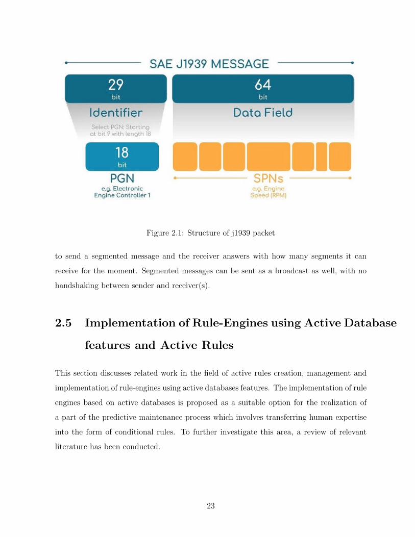
Figure 2.1: Structure of j1939 packet
to send a segmented message and the receiver answers with how many segments it can
receive for the moment. Segmented messages can be sent as a broadcast as well, with no
handshaking between sender and receiver(s).
2.5 Implementation of Rule-Engines using Active Database
features and Active Rules
This section discusses related work in the field of active rules creation, management and
implementation of rule-engines using active databases features. The implementation of rule
engines based on active databases is proposed as a suitable option for the realization of
a part of the predictive maintenance process which involves transferring human expertise
into the form of conditional rules. To further investigate this area, a review of relevant
literature has been conducted.
23
2.5.1 Idea of active rules
A modern database management system (DBMS) is far from being just a persistence mech-
anism for storing and managing data. Several fields that might be eligible with a view to
applying the behavioral facilities of database systems to it are database programming,
temporal databases, spatial databases, multimedia databases, deductive databases, and
active databases. Traditionally, DBMSs are passive. That means that database commands
(e.g., query, update, delete) are executed when requested directly by the programmer or
by the application utilizing the database. In this case, if application business logic relies on
the interaction between database entities (i.e. you cannot book the flight that is already
full), a consistency check must be implemented in every application using the database.
Active databases allow us to delegate the part of business logic that involves reactive be-
havior to DBMS. Active database features are a great fit for implementing active behaviour
and active rules. Before implementing active rules, we need to understand the structure
and classification of the rules mechanism. Traditionally, rule engine contains two types of
models[38]:
Knowledge model (description mechanism): rule model is constructed out of three com-
ponents:
• Event - describes the fact which happened and could be captured by the database
engine (i.e. insert, update).
• Condition - the context that goes along with the event (i.e. inserted value is bigger
than defined threshold).
• Action - the function to be performed based on the condition (i.e. rollback transac-
tion).
Events are categorized in several ways. By the source that generates the event: operation
(insert, update), transaction (begin, commit, abort), clock (10:00PM, every 10 seconds),
behaviour invocation (before/after operations, user-defined events), exception (e.g. secu-
rity violation). By event type: primitive (event is raised by a single operation), composite
24

(event is raised by a combination of primitive or composite events). Composite events
could be combined using logical operators (AND, OR, NOT) and more complex logic-like
sequences or a specific order of events. Complete event interactions using a variety of log-
ical operators have been proposed in the 1990s for a range of systems, including Sentinel
[11], HiPAC [16], SAMOS [23] and ODE [4]. Challenges could appear in the situations
when system is waiting for composite event E0 combined from two events (E1 + E2). And
two same type of events appear (E1, E′1) followed by E2. In this situation it is unclear
which strategy to use to combine primitive events. In [11] the approach called consump-
tion policies is proposed. It introduces four policies. Recent context combines the most
recent appropriate events (E ′1 +E2). Chronicle context considers the event appeared first
chronologically (E1 + E2). Used events E1 and E2 are removed from future consideration.
Continuous context uses concept of sliding window. Every time the event of type E1
occurs the construction of new composite event starts. And when E2 arises two composite
events (E1 +E2) and (E ′1 +E2) are created. Cumulative context stores all appearances of
primitive events of type E1 and only when E2 appears it constructs new composite events
with every instance of E1. For Conditions and Actions the definition of Context is
introduced. It indicates the setting in which the condition is evaluated and action is per-
formed. DBt - the database at the start of the current transaction; DBe - the database
when the event took place; DBc - the database when the condition is evaluated; and DBa
- the database when the action is executed. Figure 2.2 demonstrates the availability of
data to different components of a rule.
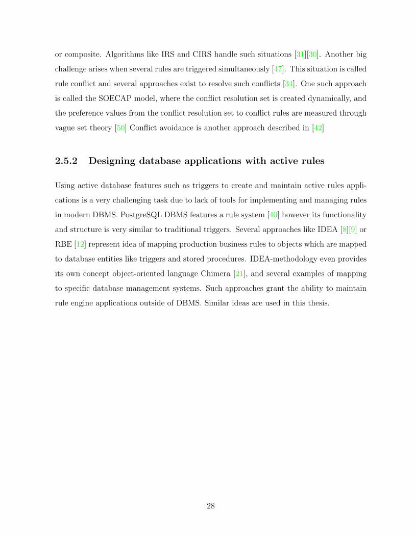
Execution model (runtime strategy): this mode describes how rules are processed at
runtime. The process is divided into five phases:
1. Signaling phase: represents the occurrence of the event generated by some event
source
2. Triggering phase: starts rules associated with corresponding events
3. Evaluation phase: evaluates conditions in triggered rules. All the rules which satisfy
these conditions form so called conflict set
25
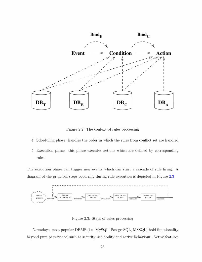
Figure 2.2: The context of rules processing
4. Scheduling phase: handles the order in which the rules from conflict set are handled
5. Execution phase: this phase executes actions which are defined by corresponding
rules
The execution phase can trigger new events which can start a cascade of rule firing. A
diagram of the principal steps occurring during rule execution is depicted in Figure 2.3
Figure 2.3: Steps of rules processing
Nowadays, most popular DBMS (i.e. MySQL, PostgreSQL, MSSQL) hold functionality
beyond pure persistence, such as security, scalability and active behaviour. Active features
26

Figure 2.4: Active rule system architecture
in DBMS are implemented using so called user-defined functions or UDFs. Even features
like machine learning techniques or statistical models which are known to be rather sophis-
ticated approaches could be integrated inside the DMBS (i.e. using MADlib [26] extension
for PostgreSQL).
Active databases are a good suit for monitoring input data sets and reacting to them
automatically based on some predefined rules. Academic literature describes several ap-
proaches based on so-called ECA (Event-Condition-Action) rules [39][19] or more advanced
technique using rule graphs named E-RG (Event-Rule Graph) rules[49]. Unlike traditional
ECA rules, the E-RG approach has only one coupling phase which can simplify rule execu-
tion and extend the semantics of rules with a rule graph (named RG), effectively capturing
the complex structure of a group of rules. In real-world applications, events that trigger
conditions and subsequent actions are not always atomic. Often, the events are complex
27
or composite. Algorithms like IRS and CIRS handle such situations [31][30]. Another big
challenge arises when several rules are triggered simultaneously [47]. This situation is called
rule conflict and several approaches exist to resolve such conflicts [34]. One such approach
is called the SOECAP model, where the conflict resolution set is created dynamically, and
the preference values from the conflict resolution set to conflict rules are measured through
vague set theory [50] Conflict avoidance is another approach described in [42]
2.5.2 Designing database applications with active rules
Using active database features such as triggers to create and maintain active rules appli-
cations is a very challenging task due to lack of tools for implementing and managing rules
in modern DBMS. PostgreSQL DBMS features a rule system [40] however its functionality
and structure is very similar to traditional triggers. Several approaches like IDEA [8][9] or
RBE [12] represent idea of mapping production business rules to objects which are mapped
to database entities like triggers and stored procedures. IDEA-methodology even provides
its own concept object-oriented language Chimera [21], and several examples of mapping
to specific database management systems. Such approaches grant the ability to maintain
rule engine applications outside of DBMS. Similar ideas are used in this thesis.
28

Chapter 3
Architecture of a cyber-physical
system for predictive maintenance
This chapter introduces the architecture of a proposed system that implements the predic-
tive maintenance function for FMS. The proposed architecture is based on specifications
of an IoT cyber-physical system for STO. The specification is divided into several sec-
tions and each section serves as a requirement for parts of the whole system such as the
physical architecture of gateway devices, distributed network structure, communication
services and predictive maintenance requirements. This chapter describes the whole FMS
structure, but focuses on details of the gateway device installed on the bus, also called
the vehicle node (VN). We describe the interaction between the VN-gateway and external
systems such as server leader node (SLN), root node (RN) and vehicle sensor network.
We are using modeling techniques such as UML notation and its extensions for modeling
embedded systems, SysML and MARTE.
3.1 Conceptual scheme of the cyber-physical system
Most modern control systems responsible for managing distributed cyber-physical assets
cannot be located in one centralized node. This is because such systems manage large
amounts of data coming from multiple sources that are often spread around geographi-
29
cal locations (parts of the town, cities or even countries). This is especially true for the
transportation industry where we are dealing with nodes that constantly move from one
location to another. There are three main reasons for using distributed architecture, ex-
plained below:
• Speed concerns: having all the control centralized in one server node, even if this
node is a super computer holding huge computational power, will cause significant
delay because communication speeds are dependent on the quality of the network
services and on the distance between peers. Sometimes, a vehicle might move from
one city to another, and sending data to a server node located hundreds, or even
thousands, of kilometers away is not the most effective approach.
• Communication costs: costs for fast cellular data services such as LTE are still con-
siderable, and when constantly monitoring fleet containing hundreds of vehicles, com-
munication service expenses could add up to a significant amount.
• Reliability: relying on one centralized system is not a good idea when there are
hundreds of nodes simultaneously interacting with it. Breakout or event temporary
failure on the central node can cause the whole system to crash and lose a considerable
amount of data.
Considering all the drawbacks of a centralized system, we proposed a distributed ar-
chitecture of the FMS. Localized fleets are controlled by control units called server leader
nodes (SLN). SLNs are responsible for handling the connections with vehicle nodes and
accumulating and analyzing vehicle data from the vehicles that are mapped to that SLNs
local fleet. SLNs are not aware of other fleets or other SLNs. At the same time, the central
node, called the root node, is responsible for the structure of the entire system. It combines
information about all the SLNs and handles the mapping of vehicles to the SLN depending
on several factors such as location, connection speed or attachment to a specific company.
The root node is capable of analyzing the data among the whole FMS and is aware of
the states of all SLNs. It provides UI capabilities for interacting with human specialists
30
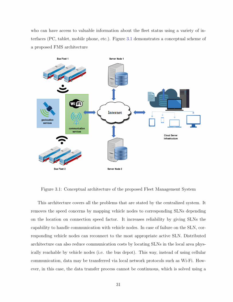
who can have access to valuable information about the fleet status using a variety of in-
terfaces (PC, tablet, mobile phone, etc.). Figure 3.1 demonstrates a conceptual scheme of
a proposed FMS architecture
Figure 3.1: Conceptual architecture of the proposed Fleet Management System
This architecture covers all the problems that are stated by the centralized system. It
removes the speed concerns by mapping vehicle nodes to corresponding SLNs depending
on the location on connection speed factor. It increases reliability by giving SLNs the
capability to handle communication with vehicle nodes. In case of failure on the SLN, cor-
responding vehicle nodes can reconnect to the most appropriate active SLN. Distributed
architecture can also reduce communication costs by locating SLNs in the local area phys-
ically reachable by vehicle nodes (i.e. the bus depot). This way, instead of using cellular
communication, data may be transferred via local network protocols such as Wi-Fi. How-
ever, in this case, the data transfer process cannot be continuous, which is solved using a
31

local storage on the vehicle nodes.
Here it should be mentioned that the application described in this thesis operates with
the data localized to a specific vehicle rather then data across the whole fleet. That is why
the coordination of data updates between different vehicle nodes is out of the scope of the
thesis.
3.2 Modelling Cyber-Physical Systems with UML, SysML,
and MARTE
System modeling is an essential step in developing any automated system. It allows us to
design software using a modeling language. This helps to discover problems early and fix
them without rewriting the final code.
System modeling in our case is accomplished in several steps. First, we state the
problem domain based on the proposed specification, explaining the general structure of
the systems implementation. Then, in Section 2, we describe the structural modeling of the
vehicle node embedded system. This step includes the development of system and software
context block definition diagrams. Section 3 discusses the use-case modeling of system
behaviour. Section 4 describes the design of state machines for controlling the embedded
system. In Section 5, we derive information from use-case diagrams for developing a
sequence diagram using the dynamic interaction of the system entities. Section 6 describes
how the object and class structuring criteria are applied to this system. During modeling
of the system, we introduce several extensions and improvements of the design modeling
notations focused directly on IoT concepts that may help with the design of IOT-systems
and make models and interactions between entities look clearer.
3.2.1 Problem statement
The VN system that interfaces with the external environment uses diverse types of sensors
and actuators, including the SAE J1939 CAN protocol for heavy machinery. It includes
32

modules for detecting events based on input values gathered from sensors, modules for
storing sensor values in local storage, and modules responsible for interfacing with the
cloud system. The vehicle node system has a network of sensors monitoring the state
of the vehicle and generating input data for the system. The sensor network consists of
bus-integrated sensors sending data over SAE industrial protocols and external sensors
connected directly to vehicle nodes such as cameras, accelerometers and GPS. This input
data is used by several modules of the system. Modules directly accessing raw sensor
readings include:
• The persistence module which is responsible for saving values into a local database.
• The event detection module responsible for analyzing raw data using complex algo-
rithms and detecting simple events which describe the current state of the vehicle.
• The network streaming module responsible for sending raw data to the cloud over
the network connection.
• The plotting module responsible for visualization of real-time data
VN system also includes other modules such as:
• The network connection module responsible for establishing network communication
with cloud services. If this module fails to establish such a connection, the VN system
continues to operate in offline mode.
• The output signals module responsible for interacting with real-world signals (LED
signals, sound signals, etc.).
• The UI module gives users the ability to monitor the current state of the vehicle node
and its parameters.
The system could be configured by an external configuration module which defines the
initial state of the vehicle node and its operational parameters.
33
3.2.2 Structural Modeling
To determine the boundaries of the system, I first developed a conceptual structural model
of the problem domain using SysML notation block definition diagrams. This diagram
defines the boundary of the overall (hardware/software) system and software system re-
spectively.
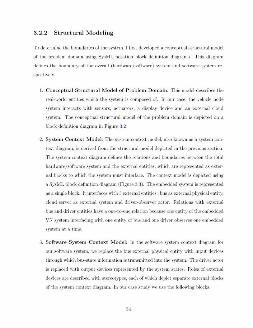
1. Conceptual Structural Model of Problem Domain: This model describes the
real-world entities which the system is composed of. In our case, the vehicle node
system interacts with sensors, actuators, a display device and an external cloud
system. The conceptual structural model of the problem domain is depicted on a
block definition diagram in Figure 3.2
2. System Context Model: The system context model, also known as a system con-
text diagram, is derived from the structural model depicted in the previous section.
The system context diagram defines the relations and boundaries between the total
hardware/software system and the external entities, which are represented as exter-
nal blocks to which the system must interface. The context model is depicted using
a SysML block definition diagram (Figure 3.3). The embedded system is represented
as a single block. It interfaces with 3 external entities: bus as external physical entity,
cloud server as external system and driver-observer actor. Relations with external
bus and driver entities have a one-to-one relation because one entity of the embedded
VN system interfacing with one entity of bus and one driver observes one embedded
system at a time.
3. Software System Context Model: In the software system context diagram for
our software system, we replace the bus external physical entity with input devices
through which bus-state information is transmitted into the system. The driver actor
is replaced with output devices represented by the system states. Roles of external
devices are described with stereotypes, each of which depict separate external blocks
of the system context diagram. In our case study we use the following blocks:
34
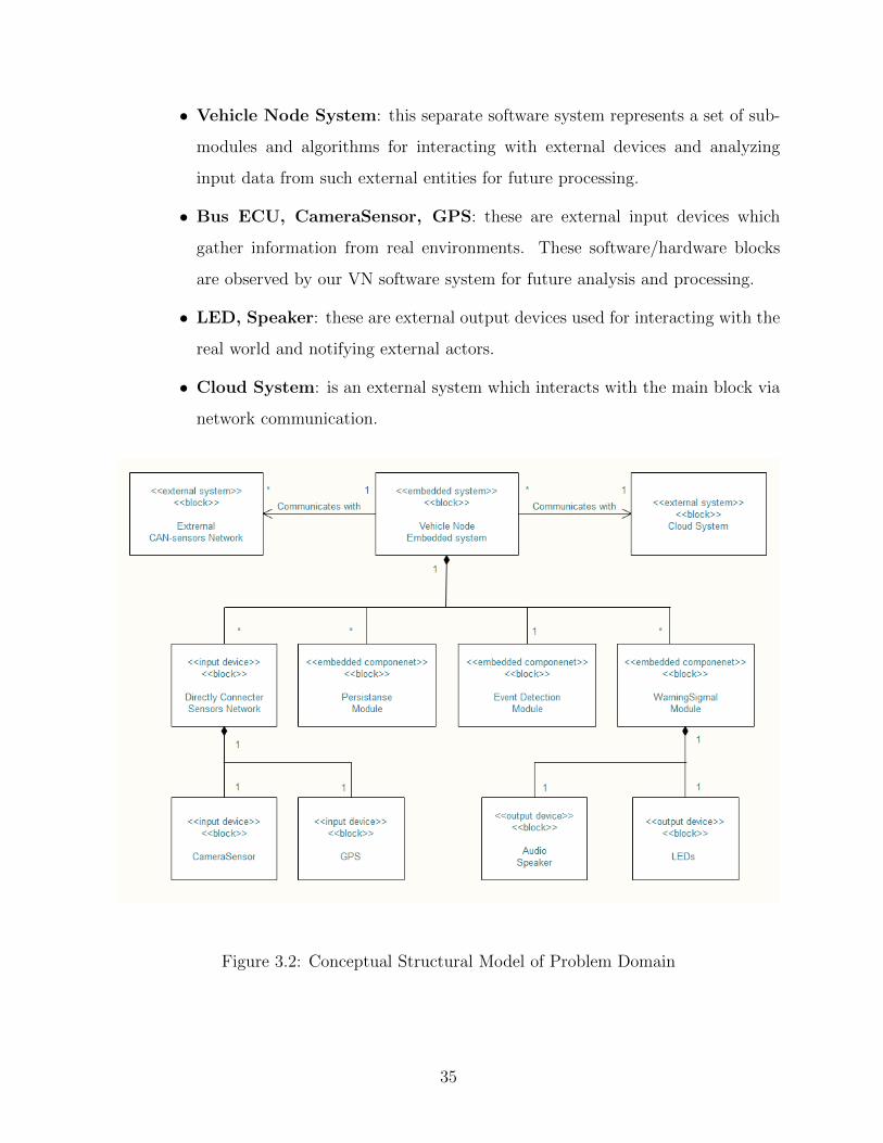
• Vehicle Node System: this separate software system represents a set of sub-
modules and algorithms for interacting with external devices and analyzing
input data from such external entities for future processing.
• Bus ECU, CameraSensor, GPS: these are external input devices which
gather information from real environments. These software/hardware blocks
are observed by our VN software system for future analysis and processing.
• LED, Speaker: these are external output devices used for interacting with the
real world and notifying external actors.
• Cloud System: is an external system which interacts with the main block via
network communication.
Figure 3.2: Conceptual Structural Model of Problem Domain
35
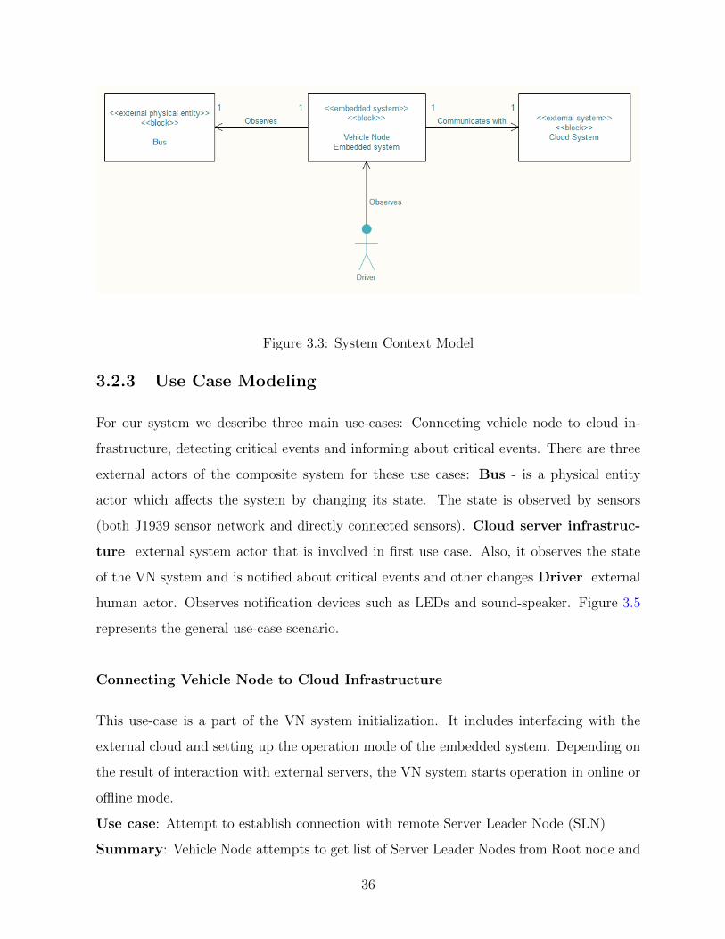
Figure 3.3: System Context Model
3.2.3 Use Case Modeling
For our system we describe three main use-cases: Connecting vehicle node to cloud in-
frastructure, detecting critical events and informing about critical events. There are three
external actors of the composite system for these use cases: Bus - is a physical entity
actor which affects the system by changing its state. The state is observed by sensors
(both J1939 sensor network and directly connected sensors). Cloud server infrastruc-
ture external system actor that is involved in first use case. Also, it observes the state
of the VN system and is notified about critical events and other changes Driver external
human actor. Observes notification devices such as LEDs and sound-speaker. Figure 3.5
represents the general use-case scenario.
Connecting Vehicle Node to Cloud Infrastructure
This use-case is a part of the VN system initialization. It includes interfacing with the
external cloud and setting up the operation mode of the embedded system. Depending on
the result of interaction with external servers, the VN system starts operation in online or
offline mode.
Use case: Attempt to establish connection with remote Server Leader Node (SLN)
Summary: Vehicle Node attempts to get list of Server Leader Nodes from Root node and
36
Figure 3.4: Software System Context Model
establish connection with one of them
Actors: External Cloud-system
Precondition: VN system in the offline mode
Main sequence:
1. VN system looks up for root node address in the configuration
2. Connects to MQTT-broker of the Root Node
3. Starts listening to updates from root node about available SLNs
4. Sends request to retrieve list of available SLNs
5. Gets list of available SLNs
37
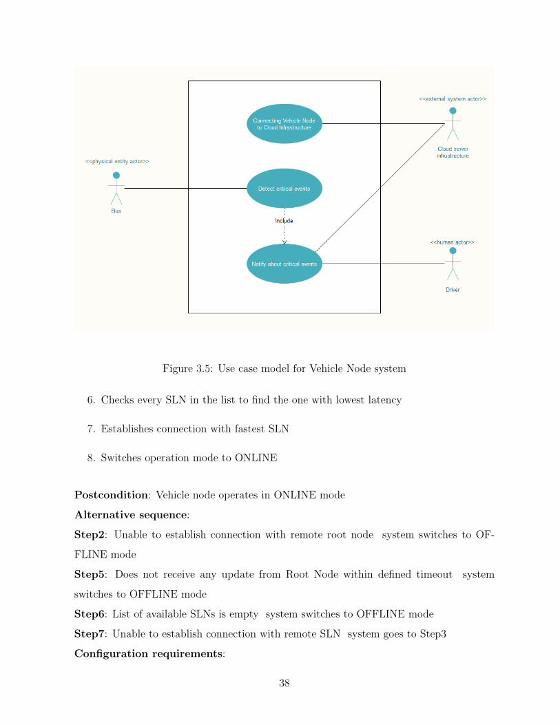
Figure 3.5: Use case model for Vehicle Node system
6. Checks every SLN in the list to find the one with lowest latency
7. Establishes connection with fastest SLN
8. Switches operation mode to ONLINE
Postcondition: Vehicle node operates in ONLINE mode
Alternative sequence:
Step2: Unable to establish connection with remote root node system switches to OF-
FLINE mode
Step5: Does not receive any update from Root Node within defined timeout system
switches to OFFLINE mode
Step6: List of available SLNs is empty system switches to OFFLINE mode
Step7: Unable to establish connection with remote SLN system goes to Step3
Configuration requirements:
38
Name: Root node address definition
Description: System gives possibility to configure Root Node address through external
configuration
Detect critical event
This use-case describes a main function of the vehicle node, analyzing raw sensor data
from external sensor networks and determining unusual behavior of the external bus sys-
tem. Determination if based on the even detecting algorithms. Determined events are
observed by several modules: the persistence module stores events in the local database,
network connection module sends detected events to the cloud infrastructure, notification
module provides information for external actors whenever a critical event is detected by
firing up LED or giving sound signal. Event detection module is described as a decompos-
able block (black box) which has raw sensor data as an input and detects critical events as
an output. The event detection algorithm itself is out of the scope of this modeling report.
Use case: Reading sensor data and detecting critical events
Summary: During normal operation, vehicle node reads sensor data, detects critical
events and notifies its observer modules
Actors: Bus, Driver
Precondition: VN system in online mode
Main sequence:
1. VN-system looks up for list of active sensors in sensor network (both Bus gateway
ECU and directly connected sensors)
2. Starts reading all available sensor data
3. Saves data into local DB and simultaneously streams data to the Cloud via network
transportation module
39

4. Event detection module reads most recent readings and determines anomalies in
time-series data using one of the predictive maintenance approaches
5. When critical event is determined, event detection module notifies its observer about
event.
6. Network transportation module sends information about critical event to the Cloud
server infrastructure.
Postcondition: Vehicle node operates in ONLINE mode
Alternative sequence:
Considering that precondition is that VN system is in ONLINE and it stays in this state
no alternative sequence is presented in the described use-case
Configuration requirement:
Name: List of sensors definition
Description: System uses list of sensors defined in local configuration database file
Name: Critical events conditions definition
Description: Thresholds of sensor values and other parameters determining critical events
could be derived from external configuration file
Inform about critical event
Use case: Notifying driver about events during operation
Summary: During normal operation, notification module observes events that are fired
by the system and notifies driver using output devices
Actors: Driver
Precondition: VN system in online mode and observing the event detection module for
events
Main sequence:
1. VN system gets notified about critical event appeared in the event detection module
40

2. VN system transits the event with parameters to the notification module
3. If event is determined as urgent for notification, the notification module warns the
Driver actor using the output devices (LED, speaker)
Postcondition: Driver is notified about the event
Alternative sequence: Step 3: if the event is not determined as urgent it is sent to
network transportation module for future processing
Configuration requirement:
Name: List of available output devices
Description: System uses list of output devices defined in local configuration database
file
Name: Definition of urgent events
Description: Thresholds defining urgent events could be derived from external configu-
ration file
3.2.4 Dynamic State Machine Modeling
This section describes the development of state machines for the vehicle node system. The
top-level state machine (Figure 3.6) consists of two sub-machines:
• Vthe VN system operational sequence, which is a composite state representing the
main operational process of the system. It is depicted in detail in Figure 3.7
• Operational conditions state machine containing two sequential sub states: bus in
garage and bus on route
Operational sequence of VN system decomposition of composite state
The following state machine diagram depicted in Figure 3.7 represents state transitions
during the initialization process which includes connecting to SLN, setting the operational
mode and starting the main loop. Transitions are described in the following annotations:
41
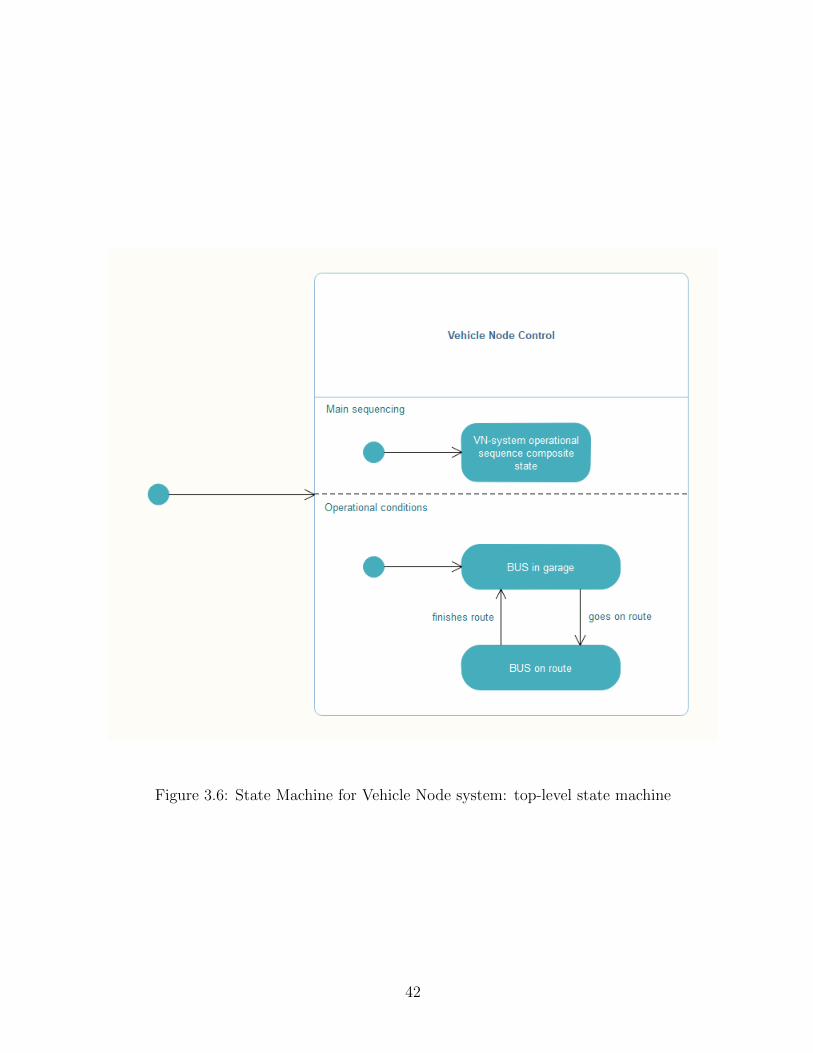
Figure 3.6: State Machine for Vehicle Node system: top-level state machine
42
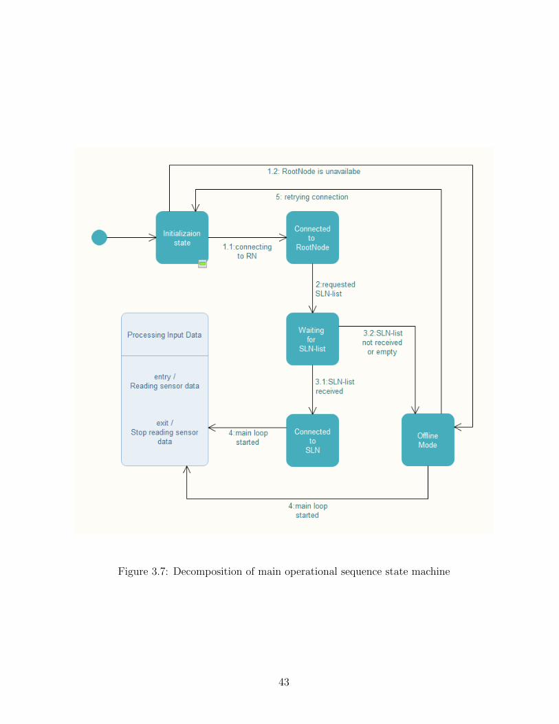
Figure 3.7: Decomposition of main operational sequence state machine
43

State:
Initialization state. At this point system has initialized all required parameters and is
aware of possibility to connect to remote root Node
Transitions:
1.1: Root node is available. System establishes connection with remote root Node server.
1.2: Root node is unavailable. System goes to offline operation mode
State:
Connected to Root node. System has successfully connected to the root node and
ready for further communication
Transitions:
2: requested SLN List. System send a request for list of currently available Server Leader
Nodes
State:
Waiting for SLN list. System is listening for updates from root node with a list of
available Server Leader Nodes
Transitions:
3.1: SLN list received. When system receives list of SLNs it chooses the fastest available
and establishes connection with it
3.2: SLN list not received or empty. If in current state system do not receive SLN-list
within defined time-out or the received SLN list is empty, system goes into offline mode
state
State:
Connected to SLN. System initializes sensors and prepares for streaming data
Transitions:
4: main loop started. Goes into main process of streaming sensor data and detecting
events
State:
Offline Mode. System in this state prepares sensors for streaming and saving data to
44
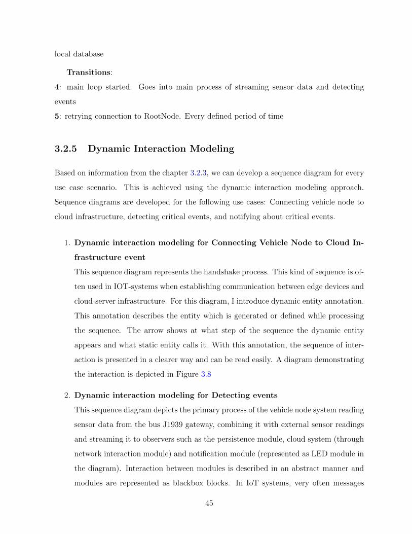
local database
Transitions:
4: main loop started. Goes into main process of streaming sensor data and detecting
events
5: retrying connection to RootNode. Every defined period of time
3.2.5 Dynamic Interaction Modeling
Based on information from the chapter 3.2.3, we can develop a sequence diagram for every
use case scenario. This is achieved using the dynamic interaction modeling approach.
Sequence diagrams are developed for the following use cases: Connecting vehicle node to
cloud infrastructure, detecting critical events, and notifying about critical events.
1. Dynamic interaction modeling for Connecting Vehicle Node to Cloud In-
frastructure event
This sequence diagram represents the handshake process. This kind of sequence is of-
ten used in IOT-systems when establishing communication between edge devices and
cloud-server infrastructure. For this diagram, I introduce dynamic entity annotation.
This annotation describes the entity which is generated or defined while processing
the sequence. The arrow shows at what step of the sequence the dynamic entity
appears and what static entity calls it. With this annotation, the sequence of inter-
action is presented in a clearer way and can be read easily. A diagram demonstrating
the interaction is depicted in Figure 3.8
2. Dynamic interaction modeling for Detecting events
This sequence diagram depicts the primary process of the vehicle node system reading
sensor data from the bus J1939 gateway, combining it with external sensor readings
and streaming it to observers such as the persistence module, cloud system (through
network interaction module) and notification module (represented as LED module in
the diagram). Interaction between modules is described in an abstract manner and
modules are represented as blackbox blocks. In IoT systems, very often messages
45
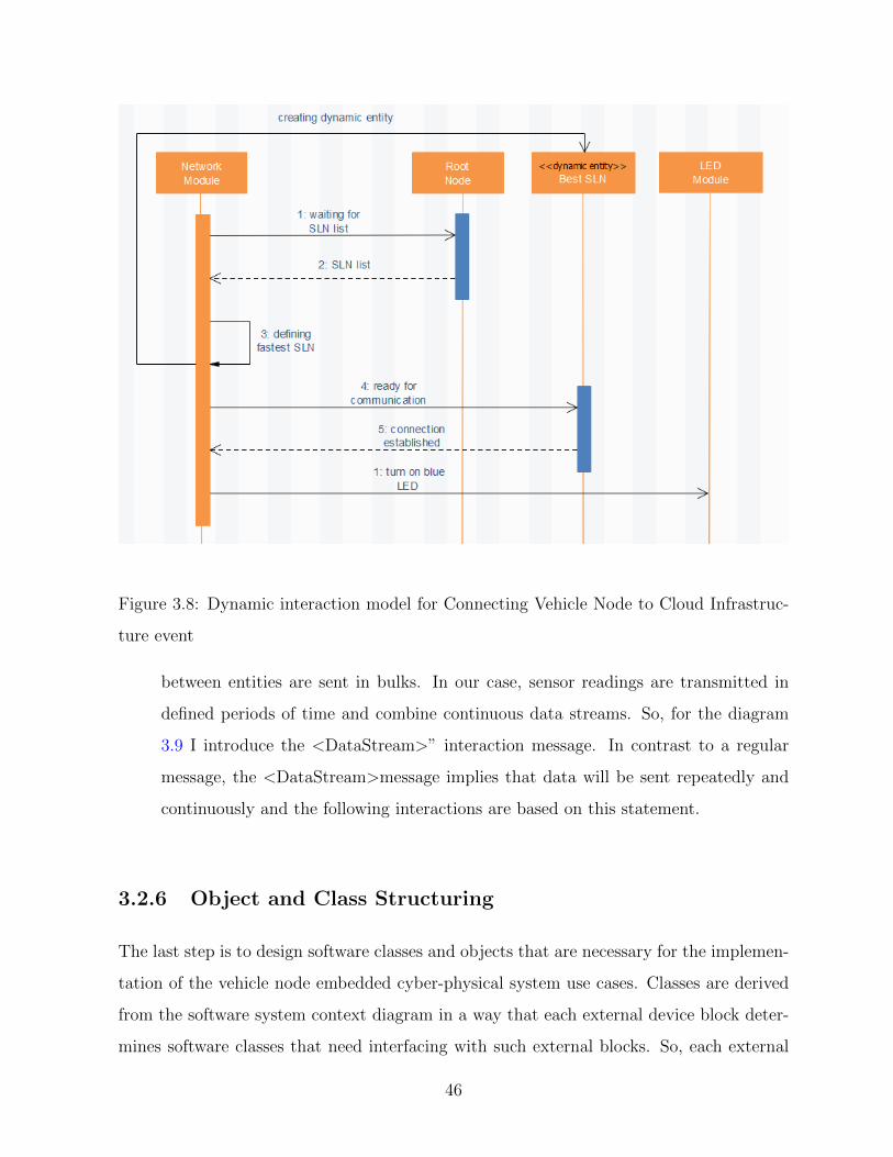
Figure 3.8: Dynamic interaction model for Connecting Vehicle Node to Cloud Infrastruc-
ture event
between entities are sent in bulks. In our case, sensor readings are transmitted in
defined periods of time and combine continuous data streams. So, for the diagram
3.9 I introduce the <DataStream>” interaction message. In contrast to a regular
message, the <DataStream>message implies that data will be sent repeatedly and
continuously and the following interactions are based on this statement.
3.2.6 Object and Class Structuring
The last step is to design software classes and objects that are necessary for the implemen-
tation of the vehicle node embedded cyber-physical system use cases. Classes are derived
from the software system context diagram in a way that each external device block deter-
mines software classes that need interfacing with such external blocks. So, each external
46
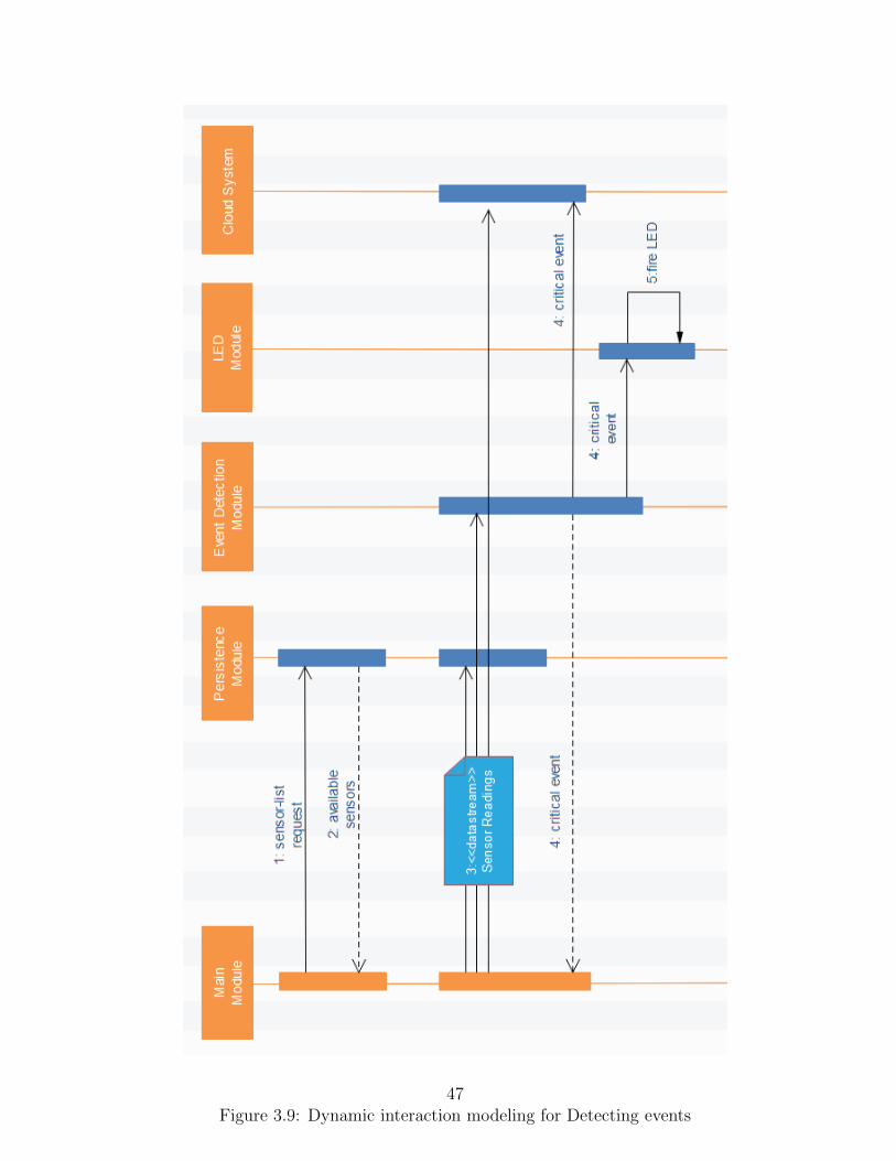
Figure 3.9: Dynamic interaction modeling for Detecting events47
input and output device depicted on the software context diagram should have a software
input/output class to interact with.
The vehicle node systems internal structure is decomposed into several software classes.
Classes marked as <input>are responsible for receiving data streams from sensor devices
and are implemented as adapter classes. These classes adapt sensor-specific drivers into
common classes that are used inside the vehicle node control modules. This way, the main
control is decoupled from external entities and allows future change of the system by adding
other types of output devices easily. The same implementation is used for output devices.
Cloud infrastructure is defined as ¡proxy¿ entity. The communication is implemented
using MQTT-protocol. Vehicle node control is presented as <state dependent control>entity.
This is a composite entity thats behaviour depends on its state. The states and behaviour
are described in detail in previous sections. The relevant diagram is depicted in Figure
3.10
3.2.7 System Configuration and Deployment
The initial configuration of the system requires specification of several parameters such as
IP-address of root servers, connection timeouts, location limitations and threshold values
for event detection. Sensors and output device lists are also taken from external config-
uration. Deployment of the system is performed in several steps which involve physical
connection of the VN-node to the bus sensor network and initialization of communication
over WAN (LTE, Wi-Fi).
3.2.8 Design Analysis
After accomplishing the modelling process, the design of the system is clearly seen from
every aspect. The possible implementation based on the presented model will have several
advantages:
• System behaviour is based on its internal states, rather than external conditions. In
48
this way, we decouple the main system control entity and external entities such as
sensor networks or cloud infrastructure.
• The decoupling lets us consider the future change of sub-systems without affecting
the behaviour of the system in general.
• Relying on the MQTT as a main communication protocol makes transferring the data
easy and reliable, however, it has some drawbacks such as lack of security features
and possible limitations of using MQTT for data streaming.
3.2.9 Results of the modeling
With the use of modelling notations such as UML, SysML and MARTE, I was able to
represent every aspect of the modelling process. This includes (i) the conceptual struc-
tural model, which uses SysML block definition diagrams to depict real-world structural
elements (such as hardware elements, software elements, or people) as blocks and defines
the relationships among these blocks, (ii) the system context model which explains asso-
ciations between the embedded system block and the external blocks and also represents
multiplicity of such associations as, for example, one-to-one or one-to-many, (iii) use case
modeling defines a sequence of interactions between the actors and the system, (iv) mod-
eling of dynamic state machines depicts the internal control and sequencing of a control
object using a state machine notation, and (v) dynamic interaction modeling represents
the system design in terms of objects as well as the message communication between them.
This kind of model is also used to depict the execution sequence of specific scenarios using
instances called messages.
The above-mentioned notations provide many opportunities to represent the system
architecture from different perspectives and could be read by both system engineers and
software engineers. However, for our specific use case of distributed IoT-based systems, I
introduced several new stereotype annotations to simplify the understanding of some parts
of the system architecture specific to IoT communication procedures. These annotations
relate, for example, to situations when the data-streaming process is used by dynamic
49
interaction model or sequence diagrams. The concept of data streaming is poorly described
in modelling languages and needs improvement, especially considering that this concept is
widely used in many modern applications such as IoT and big data analysis.
Furthermore, I added same stereotype to a class structure modeling. When it is not
enough to show that external an entity just inputs data to a system, we can use streams
to notation. This will clarify the interaction process for software engineers and will remove
possible misunderstanding about the requirements. Another stereotype annotation that I
introduced for the dynamic interaction model is dynamic entity. This stereotype explains
that the entity used in the interaction process is not defined statically, but rather is created
or defined during the run-time. The definition point is depicted using regular message
notation that is regularly used in the sequence diagram. It explains at what point the
dynamic entity is defined and what event results in the appearance of such an entity.
Using these dynamically defined/created entity annotations will make sequence diagrams
clearer to read.
3.3 Vehicle node: gateway hardware
The choices of gateway devices for IoT infrastructure nowadays are very diverse, as was
presented in Section 2.3. We had to make a choice that satisfies all the requirements for the
vehicle node and will have a relatively low cost, since it is a research project. All detailed
requirements for hardware of the vehicle node gateway are described in table 3.1:
Several devices on the market satisfy the introduced requirements, however, the price
range among them is very significant, and considering budget limitations, we decided to
build the vehicle node system on the basis of a Raspberry Pi3 portable computer. Rasp-
berry Pi3 cannot cover all the requirements introduced by STO specifications, but the
advantage of Raspberry Pi is its wide variety of supported sensors, extension boards and
external devices. For example, the reference configuration of Raspberry Pi does not sup-
port GSM or LTE communication protocols, but it supports connectivity with an extension
board called FONA 800 [2]which provides GSM connectivity. LTE support is provided with
50
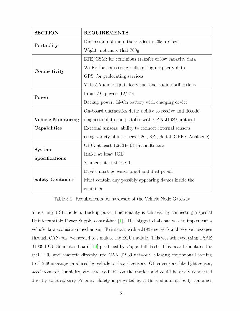
SECTION REQUIREMENTS
PortablityDimension not more than: 30cm x 20cm x 5cm
Wight: not more that 700g
Connectivity
LTE/GSM: for continious transfer of low capacity data
Wi-Fi: for transfering bulks of high capacity data
GPS: for geolocating services
Video\Audio output: for visual and audio notifications
PowerInput AC power: 12/24v
Backup power: Li-On battery with charging device
Vehicle Monitoring
Capabilities
On-board diagnostics data: ability to receive and decode
diagnostic data compaitable with CAN J1939 protocol.
External sensors: ability to connect external sensors
using variety of interfaces (I2C, SPI, Serial, GPIO, Analogue)
System
Specifications
CPU: at least 1.2GHz 64-bit multi-core
RAM: at lesat 1GB
Storage: at least 16 Gb
Safety Container
Device must be water-proof and dust-proof.
Must contain any possibly appearing flames inside the
container
Table 3.1: Requirements for hardware of the Vehicle Node Gateway
almost any USB-modem. Backup power functionality is achieved by connecting a special
Uninterruptible Power Supply control-hat [1]. The biggest challenge was to implement a
vehicle data acquisition mechanism. To interact with a J1939 network and receive messages
through CAN-bus, we needed to simulate the ECU module. This was achieved using a SAE
J1939 ECU Simulator Board [14] produced by Copperhill Tech. This board simulates the
real ECU and connects directly into CAN J1939 network, allowing continuous listening
to J1939 messages produced by vehicle on-board sensors. Other sensors, like light sensor,
accelerometer, humidity, etc., are available on the market and could be easily connected
directly to Raspberry Pi pins. Safety is provided by a thick aluminum-body container
51

sealed with rubber gaskets. This prevents two things. In the case of ignition caused by
the li-ion battery, the aluminum body keeps the heat and flames inside the container. Sec-
ondly, rubber seals provide water-proof design and dust-protection from things that can
get inside the gateway device. The photo of the vehicle mode container with insides 3.11
Functionality Configuration
Main computational unit
Raspberry Pi 3
CPU: 1.2GHz 64-bit quad-core ARMv8
RAM: 1GB
Connectivity: Ethernet, Wi-Fi, Bluetooth
Cellular connectivity Adafruit FONA 800 Shield
Backup power unit UPS Pico - I2C Control Hat
SAE CAN J1939
connectivityCopperhill SAE J1939 ECU Simulator Board
Table 3.2: Unit configuration of Vehicle Node gateway
3.4 Architecture of the Gateway Module
This section describes the proposed architecture for the framework based on the require-
ments for the application and necessity to fit the general architecture of the FMS.
3.4.1 Analysis of the requirements
The requirements for the framework are derived from several sources and are classified
based on these sources.
Requirements created by the architecture of FMS:
• The Rule Engine must be able to operate autonomously on the gateway device - to
satisfy this requirement, I used the active database features in combination with the
52
IDEA active rules methodology. This provided the ability to encapsulate the rule
engine functionality inside the data base and decouple it from rule creation and rule
management.
• Rule management software must be located on the remote centralized server and in-
teract with Gateway Rule Engine through internet - by locating rule management
software on the root node of the FMS, we provide the potential to manage all gate-
way devices and create or modify rules that are applied to vehicles containing these
gateways. Such software is responsible for receiving data about created or modified
rules from user applications and mapping it to database entities such as tables and
triggers.
• Vehicle sensor data must be collected and saved into a local database located on the
Gateway device for future analysis - this is achieved by developing a module that can
read j1939 data from the vehicle sensor network, convert it into readable format and
store it as a snapshot of a vehicle state into a local database.
STO Company requirements for the application:
• Technicians should have ability to create and input maintenance rules into the system
using predefined templates - this is achieved by analyzing a set of reference rules
provided by domain experts, classifying these rules into sub-classes and providing
ability to use these sub-classes as templates for new rules.
• Rules Management software must be accessible through internet using any type of
UI (mobile application, web-interface, desktop application) - to provide support for
a variety of possible user interfaces, the interaction between back-end and front-end
parts of the framework is implemented using RESTful API service. This way, it is
possible to plug in any possible front-end UI that supports RESTful API.
53
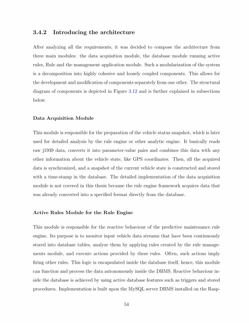
3.4.2 Introducing the architecture
After analyzing all the requirements, it was decided to compose the architecture from
three main modules: the data acquisition module, the database module running active
rules, Rule and the management application module. Such a modularization of the system
is a decomposition into highly cohesive and loosely coupled components. This allows for
the development and modification of components separately from one other. The structural
diagram of components is depicted in Figure 3.12 and is further explained in subsections
below.
Data Acquisition Module
This module is responsible for the preparation of the vehicle status snapshot, which is later
used for detailed analysis by the rule engine or other analytic engine. It basically reads
raw j1939 data, converts it into parameter-value pairs and combines this data with any
other information about the vehicle state, like GPS coordinates. Then, all the acquired
data is synchronized, and a snapshot of the current vehicle state is constructed and stored
with a time-stamp in the database. The detailed implementation of the data acquisition
module is not covered in this thesis because the rule engine framework acquires data that
was already converted into a specified format directly from the database.
Active Rules Module for the Rule Engine
This module is responsible for the reactive behaviour of the predictive maintenance rule
engine. Its purpose is to monitor input vehicle data streams that have been continuously
stored into database tables, analyze them by applying rules created by the rule manage-
ments module, and execute actions provided by these rules. Often, such actions imply
firing other rules. This logic is encapsulated inside the database itself, hence, this module
can function and process the data autonomously inside the DBMS. Reactive behaviour in-
side the database is achieved by using active database features such as triggers and stored
procedures. Implementation is built upon the MySQL server DBMS installed on the Rasp-
54
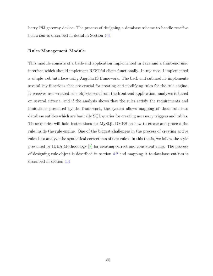
berry Pi3 gateway device. The process of designing a database scheme to handle reactive
behaviour is described in detail in Section 4.3.
Rules Management Module
This module consists of a back-end application implemented in Java and a front-end user
interface which should implement RESTful client functionally. In my case, I implemented
a simple web interface using AngularJS framework. The back-end submodule implements
several key functions that are crucial for creating and modifying rules for the rule engine.
It receives user-created rule objects sent from the front-end application, analyzes it based
on several criteria, and if the analysis shows that the rules satisfy the requirements and
limitations presented by the framework, the system allows mapping of these rule into
database entities which are basically SQL queries for creating necessary triggers and tables.
These queries will hold instructions for MySQL DMBS on how to create and process the
rule inside the rule engine. One of the biggest challenges in the process of creating active
rules is to analyze the syntactical correctness of new rules. In this thesis, we follow the style
presented by IDEA Methodology [8] for creating correct and consistent rules. The process
of designing rule-object is described in section 4.2 and mapping it to database entities is
described in section 4.4
55
Figure 3.10: Software classes in Vehicle Node System
56
Figure 3.11: Contents of the Vehicle Node Gateway based on Raspberry Pi
57

Figure 3.12: General Architecture of Rule Engine Framework
58

Chapter 4
Implementation of the Rule Engine
using Active Database features
This chapter presents the main contribution of this thesis - the design and implementation
steps of the rule engine for the predictive maintenance system based on features of active
databases. First, we try to express the rule engine system using the traditional IDEA
methodology and then present our own steps that include designing and implementing the
object model to store business maintenance rules and mapping the object model to MySQL
DBMS entities.
4.1 IDEA methodology representation of predictive
maintenance rule engine
In this section, we summarize how the definition of the running use case study would
look like when using the approach presented by the IDEA methodology [8]. The IDEA
methodology was not meant to express systems like predictive maintenance, so we also talk
about the limitations it presents.
59

4.1.1 Types
Here we define states of rules using types
1 de f i n e va lue type ru l eS t a tu s :
2 { act ive , non−a c t i v e }
3 end ;
4
5 de f i n e va lue type ruleType :
6 { immediate , accumulated , d e f e r r ed }
7 end ;
8
9 de f i n e va lue type ruleResumption :
10 { s i n g l e f i r e , mu l t i f i r e }
11 end ;
4.1.2 Classes
Since we are not fully aware of complex structure and functionality of a whole vehicle
system, we try to provide an abstract structure that is suitable for creating a variety of
rules by domain experts. Thus, classes represent sources of maintenance data, and its
attributes are specific sub-systems of the vehicle. The rule engine is represented as an
abstract class, which serves as a target for events occurring in the system.
1 de f i n e ob j e c t c l a s s sensorStreams
2 a t t r i b u t e s
3 timestamp : DATETIME,
4 o i l P r e s s u r e : INT ,
5 fuelConsumption : INT ,
6 vo l tage : INT ,
7 coolantTemp : INT ,
8 batteryTemp : INT ,
9 speed : INT ,
10 odometer : INT ,
11 accPedalAngle : INT
12 . . .
60

13 ope ra t i on s
14 read ( )
15 c on s t r a i n s
16 exhaustLeak ,
17 de f e r r ed batteryProblem ,
18 de f e r r ed beltProblem ,
19 de f e r r ed brakeProblem ,
20 coolantLeak ,
21 end ;
22 )
23
24 de f i n e ob j e c t c l a s s dtcs
25 a t t r i b u t e s
26 timestamp : DATETIME,
27 emergencyBreak : boolean ,
28 checkEngine : boolean ;
29 . . .
30 ope ra t i on s
31 read ( )
32 end ;
33
34 de f i n e ob j e c t c l a s s ru leEngine
35 end ;
36
37 de f i n e ob j e c t c l a s s maintenanceRule
38 a t t r i b u t e s
39 type : ruleType ,
40 s t a tu s : ru l eSta tus ,
41 resumption : ruleResumption ,
42 order : INT ,
43 end ;
Representing sensor streams and maintenance rules as IDEA classes has several limi-
tations. Each time we would like to extend the knowledge system by adding a new rule,
we would have to add new attributes and constraints, breaking the open-closed principle
(OCP) of software design [35]. It tightly couples object definitions with rule definitions,
61
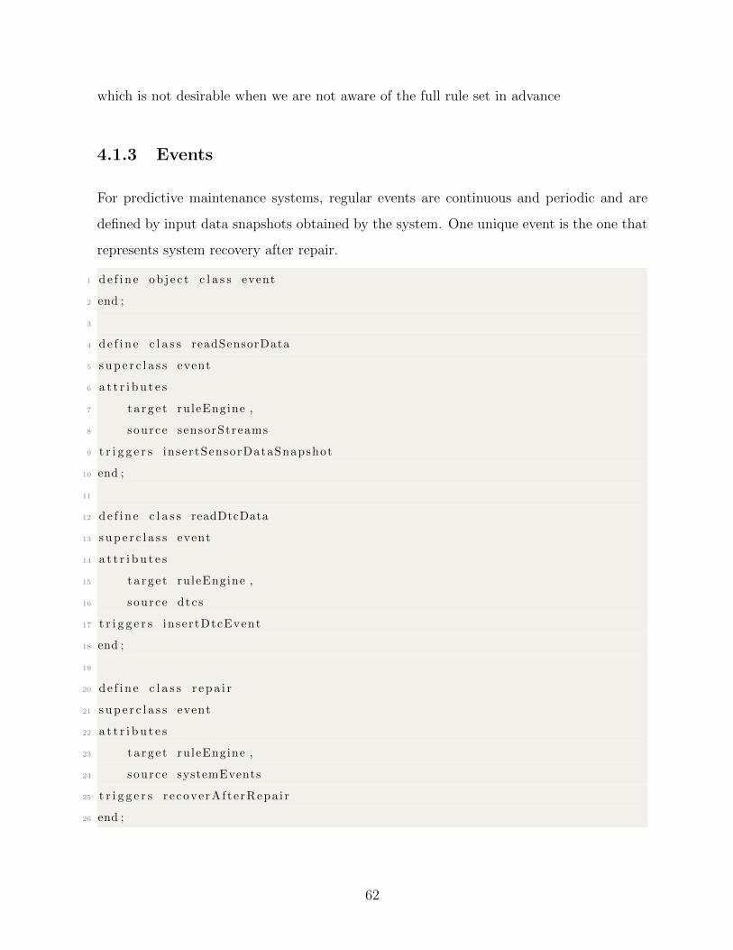
which is not desirable when we are not aware of the full rule set in advance
4.1.3 Events
For predictive maintenance systems, regular events are continuous and periodic and are
defined by input data snapshots obtained by the system. One unique event is the one that
represents system recovery after repair.
1 de f i n e ob j e c t c l a s s event
2 end ;
3
4 de f i n e c l a s s readSensorData
5 s up e r c l a s s event
6 a t t r i b u t e s
7 t a r g e t ruleEngine ,
8 source sensorStreams
9 t r i g g e r s insertSensorDataSnapshot
10 end ;
11
12 de f i n e c l a s s readDtcData
13 s up e r c l a s s event
14 a t t r i b u t e s
15 t a r g e t ruleEngine ,
16 source dtcs
17 t r i g g e r s insertDtcEvent
18 end ;
19
20 de f i n e c l a s s r e pa i r
21 s up e r c l a s s event
22 a t t r i b u t e s
23 t a r g e t ruleEngine ,
24 source systemEvents
25 t r i g g e r s r e cove rAf t e rRepa i r
26 end ;
62

4.1.4 Constraint repair triggers
Constraint repair triggers usually represent the operations that need to be conducted after
the state of the system changes and ends up in an inconsistent state which needs to be
fixed to continue rule processing. In our use case study, the system could end up in an
inconsistent state after the vehicle is returned after repair. In this situation, the state of
the system defined by fired rules would be inconsistent with the state defined by sensor
values. Thus, there is a need for specialized triggers that will match these two states.
1 de f i n e immediate t r i g g e r r ecove rAf t e rRepa i r f o r ru leEngine
2 events r e p a i r
3 ac t i on
4 c leanAct iveRulesCounters ,
5 truncateMonitorTables
6 end ;
4.1.5 Business rules
These type of rules in the our use case represent maintenance rules provided by domain
experts. Unlike the traditional IDEA methodology, where business rules are represented
as interactions between predefined objects, we are not aware of vehicle structure and only
operate with data snapshots that represent vehicle status and interactions between param-
eter values provided by the sensor network. Hence, a simple abstract rule would look as
follows:
1 de f i n e immediate t r i g g e r f i reMaintenanceEvent f o r sensorStreams
2 events readSensorData
3 cond i t i on sensorStreams (S) , dtcs (D) occurred (S , D) ,
4 D. emergencyBrake = 1 , S . speed > 100
5 a c t i on s f i r e ( r e su l tEvent )
6 end ;
Expressing maintenance rules using the IDEA methodology does not provide the desired
flexibility and readability due to the nature of the conditions used in maintenance rules.
63

These conditions are complex structures which often utilize data that is not available from
the current status of the system and need additional context to be gathered from past or
future observations. The Chimera language does not the have capability to express such
structures, thus we need to develop our own classes and methodology to map these rules
to software classes and database entities.
4.2 Designing abstract rule definitions
This section describes the process of classifying business rules and its components using
the proposed methodology. With this classification we can design software classes that are
necessary for implementing the rule management module of the framework. Organizing
rules as objects (entities of rule classes) gives developer the ability to provide better control
over the constraints, correctness and consistency of created rules rather then trying to work
directly with rules presented as database entities. To be able to manage and maintain rules
efficiently, we need to define data structures to hold rule objects. To provide the maximum
possible functionality, we analyze several specific rules obtained from domain experts. This
way, the abstract rule class can hold different combinations of events and conditions and
give users of the framework the ability to create a huge variety of rules to cover a large set
of vehicle states and maintenance decision events.
4.2.1 Example maintenance rules
During interviews with domain experts (STO technicians and engineers), we have acquired
several rules which we are using as a base point for classifying maintenance rules and
events. The rules are described below:
1. If fuel consumption exceeds value 12, with oil pressure falling lower than 35 - check
for problem:
• Check exhaust leak
64
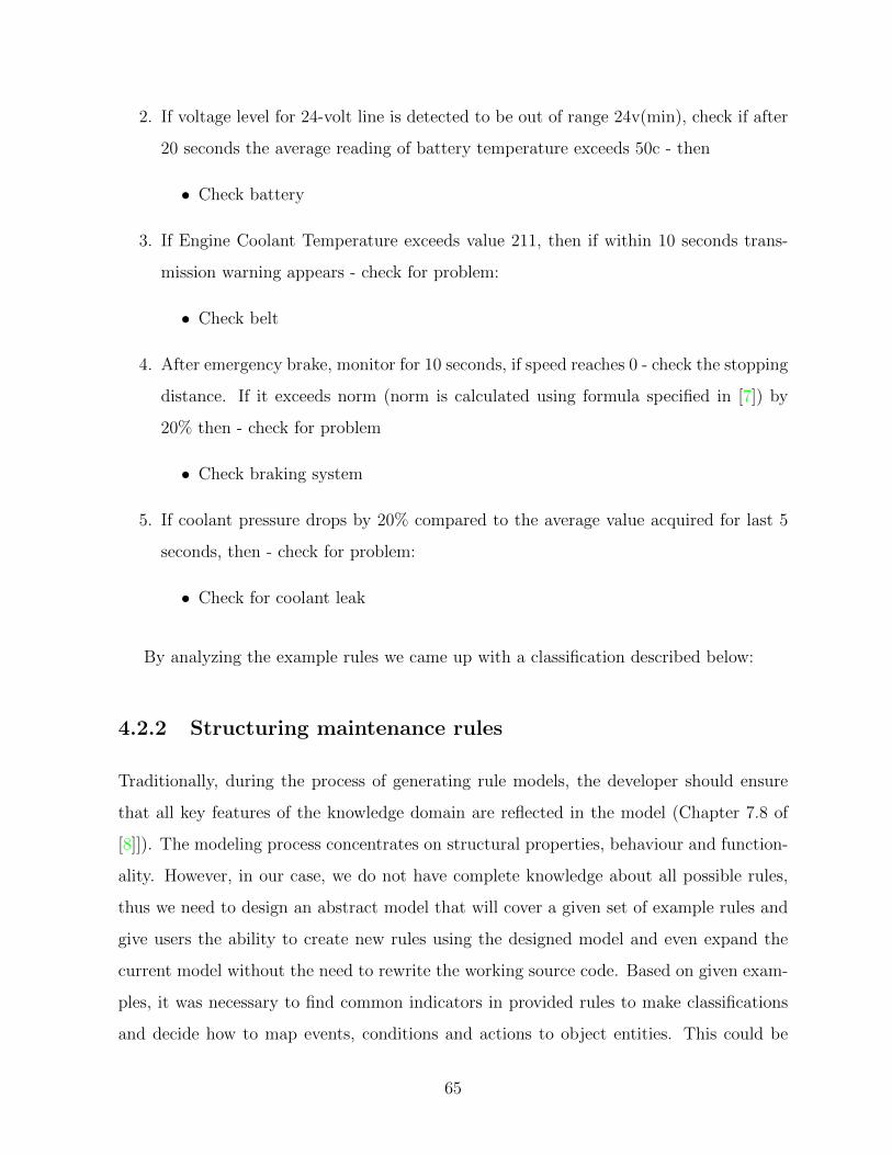
2. If voltage level for 24-volt line is detected to be out of range 24v(min), check if after
20 seconds the average reading of battery temperature exceeds 50c - then
• Check battery
3. If Engine Coolant Temperature exceeds value 211, then if within 10 seconds trans-
mission warning appears - check for problem:
• Check belt
4. After emergency brake, monitor for 10 seconds, if speed reaches 0 - check the stopping
distance. If it exceeds norm (norm is calculated using formula specified in [7]) by
20% then - check for problem
• Check braking system
5. If coolant pressure drops by 20% compared to the average value acquired for last 5
seconds, then - check for problem:
• Check for coolant leak
By analyzing the example rules we came up with a classification described below:
4.2.2 Structuring maintenance rules
Traditionally, during the process of generating rule models, the developer should ensure
that all key features of the knowledge domain are reflected in the model (Chapter 7.8 of
[8]]). The modeling process concentrates on structural properties, behaviour and function-
ality. However, in our case, we do not have complete knowledge about all possible rules,
thus we need to design an abstract model that will cover a given set of example rules and
give users the ability to create new rules using the designed model and even expand the
current model without the need to rewrite the working source code. Based on given exam-
ples, it was necessary to find common indicators in provided rules to make classifications
and decide how to map events, conditions and actions to object entities. This could be
65
achieved by converting condition components into logical statements containing mathe-
matical equations that could be used to describe rules. To describe rules systematically,
every rule is structured using a standard ECA scheme. This scheme, however, was modi-
fied and extended to particularly express vehicle maintenance rules. We try to follow the
methodology described in [39] to express the rule model. The knowledge model is used for
expressing rule structures and the execution model represents the steps of rule execution.
Knowledge model (description mechanism):
Same to the traditional definition of a knowledge model described in [39], we construct
maintenance rules out of three main components: event, condition and action. However,
for the implementation of maintenance rules, we extend traditional definitions and present
them as follows:
Events: our system can observe 3 types of events:
• SensorSnapshotEvent : this event represents the appearance of a new sensor-data
snapshot in the system. This type of event is usually observed periodically (depending
on the data acquisition module heartbeat) and is attached to the INSERT operation
of a table responsible for storing sensor-data (e.g. Rule 1).
• ResultEvent : this type of event is fired as a result of successful rule execution. It is
attached to the INSERT operation of a table that tracks the appearance of resulting
events.
• ExternalEvent : these events are fired directly by vehicles in the ECU module. Usually
these are DTCs (diagnostic trouble codes). The data acquisition module monitors
these types of events and logs them into the database (e.g. Rule 4 is triggered by
emergency-brake event).
Conditions: conditions classification for predictive maintenance rules presents signifi-
cant challenges and requires extension of traditional definitions due to the nature of moving
systems that produce data continuously. Moreover, they often require historical data or
66
data from future observations to make a final decision on whether constraints of the con-
dition are satisfied or not. Based on the provided rule examples, we classify conditions as
follows:
• Immediate: this type of condition checks for a relation between parameter values
acquired at the moment of event triggering. It is divided into two sub-classes:
– Internal : uses data from the current context that goes along with the event
(recently inserted parameter values) and checks if the relation between such
parameters follow some specified formula (e.g. Rule 1).
– External : checks for current immediate status of external context, such as ex-
ternal events or triggered result events.
• Accumulated : uses data acquired in previous iterations of observation process. Re-
duce functions like AVG or SUM could be applied to accumulated data, and after
that, the condition is estimated using generated data in some specified formula (e.g.
Rule 5).
• Deferred : this condition class defers rule firing for a specified period of time (or num-
ber of iterations). The condition is estimated continuously during the deferred period
or at the end of it and fires the resulting event if the condition is satisfied. Deferred
conditions could be classified by termination strategy of monitoring as follows:
– TimePointTermination: this type of termination strategy monitors specified
parameters for a defined time period (or number of iterations) and after that,
estimates inner conditions based on accumulated data (e.g. Rule 4) and fires a
resulting event.
– ConditionalTermination: while in monitoring phase, this type of termination
strategy constantly estimates inner condition and if it is satisfied at some point
fires a result event.
It should be mentioned that inner conditions inside termination strategies could be
Immediate (e.g. Rule 3 uses external condition) or accumulated (e.g. Rule 4 uses
67
accumulated data to estimate complex formula).
• Composite: this condition contains a combination of different condition classes com-
bined by logical operators. Such a condition is used most frequently when creating
complex predictive maintenance rules.
Actions: in the case of predictive maintenance use case, the resulting action of the
rule will be some maintenance prediction or diagnosis which informs the user of the system
and at the same time can trigger another rule that has a ResultEvent object in the event
section. Actions could be classified by prediction time and by importance as follows:
• Warning - this type of action informs that with the current vehicle status predicted,
the event will likely appear after a predefined time.
• Critical - such action informs that immediate attention is required from technical
staff, meaning that with current status of the system predicted, event could appear
any moment.
• Real-time - this type of action informs that a specified event is observed at this very
moment. This is not a prediction but rather a final diagnosis based on current vehicle
status.
The categorization of rule components presented above provides extra level of conve-
nience for the development of rule maintenance applications giving the ability to map rule
categories to software classes.
The abstract scheme of component relationship is depicted in 4.1
Execution model (runtime strategy):
This model represents the steps taken while executing the rule. This is how execution steps
are implemented in the presented use case:
1. Signaling phase: represented by SQL INSERT into one of the monitored tables.
Generated by data acquisition module.
68
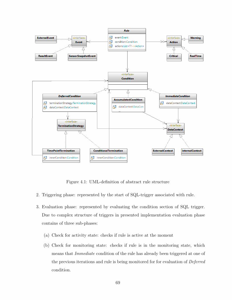
Figure 4.1: UML-definition of abstract rule structure
2. Triggering phase: represented by the start of SQL-trigger associated with rule.
3. Evaluation phase: represented by evaluating the condition section of SQL trigger.
Due to complex structure of triggers in presented implementation evaluation phase
contains of three sub-phases:
(a) Check for activity state: checks if rule is active at the moment
(b) Check for monitoring state: checks if rule is in the monitoring state, which
means that Immediate condition of the rule has already been triggered at one of
the previous iterations and rule is being monitored for for evaluation of Deferred
condition.
69
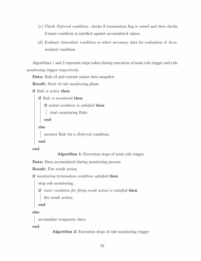
(c) Check Deferred condition: checks if termination flag is raised and then checks
if inner condition is satisfied against accumulated values.
(d) Evaluate Immediate condition or select necessary data for evaluation of Accu-
mulated condition
Algorithms 1 and 2 represent steps taken during execution of main rule trigger and rule
monitoring trigger respectively.
Data: Rule id and current sensor data snapshot
Result: Start of rule monitoring phase
if Rule is active then
if Rule is monitored then
if initial condition is satisfied then
start monitoring Rule;
end
else
monitor Rule for a Deferred condition;
end
end
Algorithm 1: Execution steps of main rule trigger
Data: Data accumulated during monitoring process
Result: Fire result action
if monitoring termination condition satisfied then
stop rule monitoring;
if inner condition for firing result action is satisfied then
fire result action;
end
else
accumulate temporary data;
end
Algorithm 2: Execution steps of rule monitoring trigger
70
4.2.3 Mapping rules to software classes
Unlike the IDEA Methodology which focuses on precisely modeling every specific subsystem
in detail using Chimera language, we focus on modeling abstract rules as a composition of
corresponding components (events, condition and actions). This level of abstraction lets
us present the rule as a family of interchangeable behaviours. This approach is known
as strategy pattern, as presented in [22]. It not only provides the potential to create a
huge variety of rule objects at runtime, but also provides a high level of scalability for
the rule engine framework, which allows easy expansion of rule definition in the future
without changing the working code. This approach perfectly corresponds with the open-
closed principle of software development presented by [35], such as: the rule class can allow
its behaviour to be extended without changing its source code. Appendix A provides the
source code that represents the implementation of a rule structure.
4.3 Designing the database scheme for Active Rules
representation
Generally, active business rules and reactive behaviour are reflected in active databases as
triggers. The trigger structure is almost identical to the scheme of ECA rules. That is
why for most situations, mapping of business rules could be performed relatively easily by
directly converting the business logic of rules into triggers and storing them inside databases
which support active features. However, in the case of vehicle predictive maintenance, rules
are often more complex and go beyond the standard definition of ECA rules. This section
describes which additional steps in database design were taken for encapsulating rule engine
features inside DBMS.
4.3.1 Storing dynamic data
Input sensor streams and maintenance events fired as a result of rule processing are the
main sources of dynamic data in the system. This kind of data is constantly monitored
71

by the system and every update triggers the conditional check over the newly acquired
data. For this reason, it was important to design the database scheme in a way that active
database features such as triggers could be attached to update events. The data acquisition
module receives sensor data as a set of key-value pairs, where key holds the description
of the parameter (e.g. current speed, oil temperature) and value holds the value of the
selected parameter in specific defined units. All the acquired parameters construct the
snapshot of the whole vehicle system at the defined time. Having a traditional relational
database system such as MySQL meant that we stored every acquired snapshot as a row
of tables with a unique ID and current time-stamp (depicted in Figure 4.2). This does not
seem very effective at first, however, this is a relevant design when it comes to working with
all the acquired data inside the triggers where it is possible to have immediate access to all
the inserted parameters and their current values. At the same time, we duplicate all the
sensor parameters in a separate table called sensors (depicted in Figure 4.2), which allows
storage of additional information such as full descriptions or availability flags. By design,
the number of parameters in the sensors table always corresponds to columns defined in
a snapshot in the sensor-streams table. For test application, we are using one table for
all sensor streams; however, for real application, all sensors could be grouped by some
attribute in such a way that every rule will likely utilize sensors from the same group. This
attribute could be defined as a vehicle subsystem for example.
The same architecture is used for storing resulting events. The main difference is that
instead of value, every event has a flag of Boolean type representing if the event has been
fired (depicted in Figure 4.3). Result events appear in the system, rarely comparing to
sensor stream data, which is why if the rule has a ResultEvent class as a starting event,
then the trigger is attached to corresponding events-stream tables. This is discussed further
in section 4.4.
4.3.2 Storing rule meta-data
While the trigger itself holds a sufficient amount of information about the structure of a
simple rule, complex rule objects that are used in the presented framework require the stor-
72

Figure 4.2: Database tables for sensor data streams information
age of additional metadata. This metadata is used to represent the relationship between
components of the rule and for convenience of the rule maintenance process. At the same
time, since rule engine functionality is fully encapsulated inside DBMS, we need to store
operational parameters necessary to track temporary data that is generated; for example,
during monitoring of Deferred conditions. The ability to maintain rules is a crucial func-
tionality of the framework and storing meta-data provides features for rule classification,
displaying and editing.
Static meta-data tables
Rule is a main entity of a rule engine, so tables are organized as relations between rule
tables and tables representing other components of the rule, such as starting events and
resulting actions. Components have a many-to-many relationship and are implemented as
join tables (Figure 4.4) To keep these relations is also important for checking a property
of action rules called rule termination. This is explained in detail in 4.5.1.
73
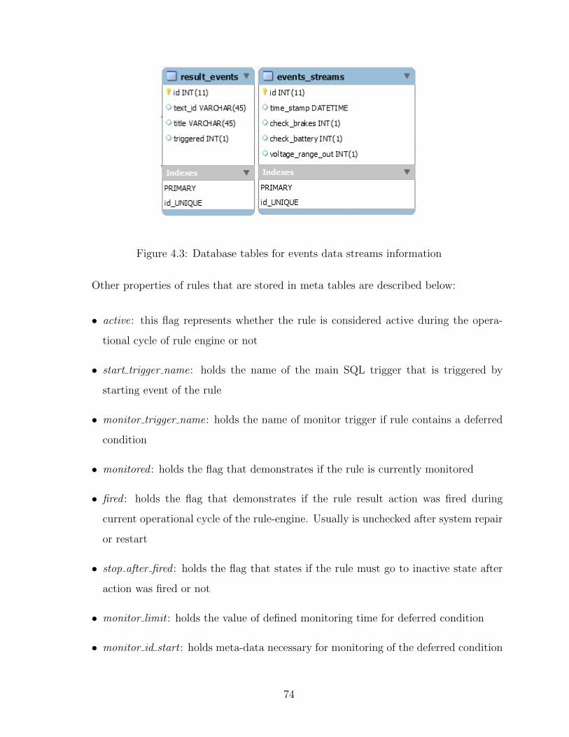
Figure 4.3: Database tables for events data streams information
Other properties of rules that are stored in meta tables are described below:
• active: this flag represents whether the rule is considered active during the opera-
tional cycle of rule engine or not
• start trigger name: holds the name of the main SQL trigger that is triggered by
starting event of the rule
• monitor trigger name: holds the name of monitor trigger if rule contains a deferred
condition
• monitored : holds the flag that demonstrates if the rule is currently monitored
• fired : holds the flag that demonstrates if the rule result action was fired during
current operational cycle of the rule-engine. Usually is unchecked after system repair
or restart
• stop after fired : holds the flag that states if the rule must go to inactive state after
action was fired or not
• monitor limit : holds the value of defined monitoring time for deferred condition
• monitor id start : holds meta-data necessary for monitoring of the deferred condition
74
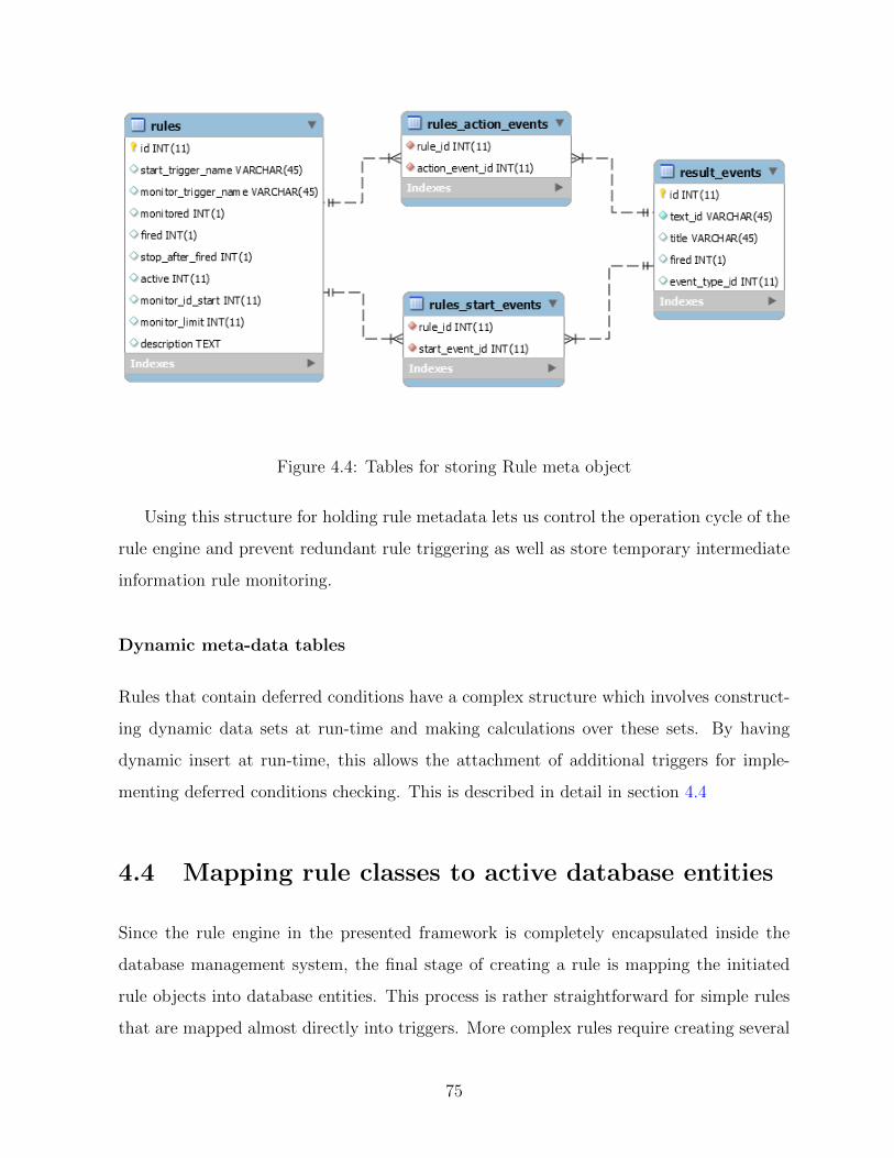
Figure 4.4: Tables for storing Rule meta object
Using this structure for holding rule metadata lets us control the operation cycle of the
rule engine and prevent redundant rule triggering as well as store temporary intermediate
information rule monitoring.
Dynamic meta-data tables
Rules that contain deferred conditions have a complex structure which involves construct-
ing dynamic data sets at run-time and making calculations over these sets. By having
dynamic insert at run-time, this allows the attachment of additional triggers for imple-
menting deferred conditions checking. This is described in detail in section 4.4
4.4 Mapping rule classes to active database entities
Since the rule engine in the presented framework is completely encapsulated inside the
database management system, the final stage of creating a rule is mapping the initiated
rule objects into database entities. This process is rather straightforward for simple rules
that are mapped almost directly into triggers. More complex rules require creating several
75
triggers attached to different database events and tables. The mapping process to the
Oracle DBMS is described in Chapter 14 of [8]. Although in our case, the mapping process
differs significantly because of structural differences in rule object descriptions, it still
follows the same idea of dividing the whole process into defined steps.
4.4.1 Mapping rule meta-data
First we create a record in a meta-data table for every rule.
1 INSERT INTO ‘ ru le−engine ‘ . ‘ ru l e s ‘ ( ‘ s t a r t t r i g g e r name ‘ , ‘
monitor tr igger name ‘ , ‘ monitored ‘ , ‘ f i r e d ‘ , ‘ s t o p a f t e r f i r e d ‘ , ‘ a c t ive
‘ , ‘ mon i t o r i d s t a r t ‘ , ‘ mon i to r l im i t ‘ , ‘ d e s c r i p t i on ‘ )
2 VALUES ( ’ s t a r t t r i g g e r r u l e 1 ’ , ’ mon i t o r t r i g g e r r u l e 1 ’ , ’ 0 ’ , ’ 0 ’ , ’ 1 ’ , ’ 1 ’
, ’ 1 ’ , ’ 15 ’ , ’ Monitors vo l t age f a l l and then f o l l ow s with batte ry
temperature check ’ ) ;
Auto-generated value of ’ID’ field is used as identifier for triggers that represent condition
parts. For example, for generated ID = 7 we create new trigger like this:
1 CREATE TRIGGER ‘ ru le−engine ‘ . ‘ t r i g g e r ma i n ru l e 7 ‘
Mapping starting events
Because of the nature of sensor network systems which produce information constantly,
every rule that depends on a particular parameter must be aware of any updates hap-
pening to this parameter. This is why triggers must be attached to AFTER INSERT
event. For mapping starting events, there is a choice of what table to attach a trigger
to. If the rule contains a ResultEvent or ExternalEvent object in a set of starting events,
then the trigger is attached to a corresponding database table. Otherwise, the trigger is
attached to a sensor-streams table. The reason for this is because INSERT operations
on events-stream occur much more rarely than on sensor-streams. So, if a rule contains a
ResultEvent, even in combination with other SensorSnapshotEvents, it would be triggered
only if a specific complex event is fired. This approach reduces stacks of triggers, thus
76

lowering the load on the rule engine system in DBMS. The following listings demonstrate
how the event part on a trigger is constructed based on the starting event of the rule object:
Trigger with SensorSnapshotEvent as starting event
1 CREATE TRIGGER ‘ ru le−engine ‘ . ‘ t r i g g e r ma i n ru l e 7 ‘
2 AFTER INSERT ON ‘ sensor−streams ‘
Trigger with ResultEvent as starting event
1 CREATE TRIGGER ‘ ru le−engine ‘ . ‘ t r i g g e r ma i n ru l e 7 ‘
2 AFTER INSERT ON ‘ events−streams ‘
4.4.2 Mapping conditions
Every condition mapping is divided into two types, which depends on whether the con-
dition check was called from SensorSnapshotEvent or from one of the predefined events
(ExternalEvent or ResultEvent). Depending on the source of the event, sensor-data context
for the condition will be internal or external. Internal data is acquired from the same table
record that the trigger was triggered from, so we can use NEW.data notation to obtain
the external data context we need to run the extra query.
Immediate conditions
Mapping these kind of conditions is rather straightforward. It is represented in the following
listings.
1 IF (
2 (NEW. fue l consumpt ion > 10) AND
3 (NEW. o i l p r e s s u r e < 35)
4 )THEN
5 CALL de f i n ed a c t i o n (NEW. time stamp , r u l e i d ) ;
6 CALL log even t (SYSDATE(3) , 1 , ’ a c t i on f i r e d ’ , ’ d e f i ned ac t i on ’ ) ;
7 END IF ;
Listing 4.1: Immediate condition with Internal data context SQL-code
77

For external data context values should be acquired from external table before applying
to conditional statement.
1 ###ge t t i ng most r e c ent s enso r data
2 SELECT max( id ) FROM senso r s t r eams INTO max id ;
3 SELECT speed , odometer FROM senso r s t r eams
4 WHERE id = max id
5 INTO cur r ent speed , c u r r e n t d i s t a n c e ;
6
7 IF (
8 ( cu r r en t sp e ed > 30) AND
9 ( c u r r e n t d i s t a n c e < 4000) )
10 THEN
11 CALL de f i n ed a c t i o n (NEW. time stamp , r u l e i d ) ;
12 CALL log even t (SYSDATE(3) , 1 , ’ a c t i on f i r e d ’ , ’ d e f i ned ac t i on ’ ) ;
13 END IF ;
Listing 4.2: Immediate condition with External data context SQL-code
Accumulated conditions
For mapping Accumulated conditions it is necessary to accumulate set of previously stored
values and apply defined reduce function to it.
1 DECLARE accumulate t ime INT unsigned DEFAULT 5 ;
2 IF ( SELECT AVG( coo l an t p r e s s u r e )
3 FROM senso r s t r eams
4 WHERE id > (NEW. id − accumulate t ime )
5 AND id <= NEW. id ) > (NEW. coo l an t p r e s s u r e + th r e sho l d )
6 THEN
7 CALL f i r e c o o l a n t l e a k (SYSDATE(3) , r u l e i d ) ;
8 CALL log even t (SYSDATE(3) , 1 , ’ a c t i on f i r e d ’ , ’ c o o l an t l e a k ’ ) ;
9 END IF ;
Listing 4.3: Accumulated condition SQL-code
78

Deferred conditions
This class of conditions represent the biggest challenge to implement using active database
features. An even bigger challenge is to maintain it, because MySQL does not provide any
convenient tools for managing triggers. Hence, the idea of adding meta-tables for mon-
itoring deferred conditions and attaching monitor triggers to these tables gives sufficient
flexibility and a clearer view on the structure of the rule engine.
Deferred conditions contain of two triggers:
• start trigger, which is the same as for Immediate conditions. But instead of calling
result events it insert a record with current operational values into monitoring meta-
table.
• monitor trigger is attached to monitoring meta-table. Result action event if fired
from here based on the termination strategy and inner condition.
1 IF ( monitored = 0) THEN
2 IF (NEW. coolant temp > 211) THEN
3 UPDATE ru l e s SET monitored = 1 WHERE id = r u l e i d ;
4 CALL log even t (SYSDATE(3) , 3 , ’ monitor s t a r t ’ , ’ r u l e 3 s t a r t ed
monitor ing ’ ) ;
5 CALL mon i t o r ru l e 3 ( ( mon i t o r i d s t a r t + mon i t o r l im i t ) ) ;
6 END IF ;
7 ELSE
8 CALL mon i t o r ru l e 3 ( ( mon i t o r i d s t a r t + mon i t o r l im i t ) ) ;
9 END IF ;
Listing 4.4: Deferred condition start trigger
1 IF (NEW. id >= NEW. mon i t o r l im i t i d ) THEN
2 CALL s top ru l e mon i t o r ( r u l e i d , NEW. id ) ;
3 ELSE
4 IF (NEW. speed = 0) THEN #Termination cond i t i on
5 IF (NEW. t r a v e l e d d i s t a n c e > 100) THEN #Inner cond i t i on
6 CALL s top ru l e mon i t o r ( r u l e i d , NEW. id + 1) ;
7 CALL f i r e c h e c k b r a k e s (NOW(3) , r u l e i d ) ;
79

8 CALL log even t (SYSDATE(3) , r u l e i d , ’ a c t i on f i r e d ’ , ’ Check
Brakes f i r e d a f t e r monitor ing ’ ) ;
9 ELSE
10 CALL s top ru l e mon i t o r ( r u l e i d , NEW. id + 1) ;
11 CALL log even t (SYSDATE(3) , r u l e i d , ’ a c t i on f i r e d ’ , ’ Check Belt
f i r e d a f t e r monitor ing ’ ) ;
12 END IF ;
13 END IF ;
14 END IF ;
Listing 4.5: Deferred condition monitor trigger with ConditionalTermination strategy
1 IF (NEW. id >= NEW. mon i t o r l im i t i d ) THEN # Time po int o f te rminat ion
2 IF (NEW. battery temp > 50) THEN # Inner cond i t i on
3 CALL s top ru l e mon i t o r ( r u l e i d , NEW. id + 1) ;
4 CALL f i r e c h e c k b a t t e r y (SYSDATE(3) , r u l e i d ) ;
5 CALL log even t (SYSDATE(3) , r u l e i d , ’ a c t i on f i r e d ’ , ’ Check
batte ry f i r e d a f t e r monitor ing ’ ) ;
6 ELSE
7 CALL s top ru l e mon i t o r ( r u l e i d , NEW. id + 1) ;
8 CALL log even t (SYSDATE(3) , r u l e i d , ’ monitor stopped ’ , ’ Rule 2
monitor ing stopped without ac t i on ’ ) ;
9 END IF ;
10 END IF ;
Listing 4.6: Deferred condition with TimePointTermination strategy
SQL-implementations of all example rules that were used for writing this thesis are
presented in Appendix B
4.5 Challenges of using active rules for rule-engine
development
The process of developing and utilizing active rules introduces several challenges and prob-
lems due to the unstructured and unpredictable nature of rule processing. Inside a large,
80
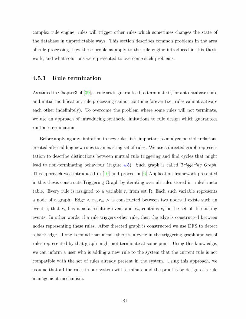
complex rule engine, rules will trigger other rules which sometimes changes the state of
the database in unpredictable ways. This section describes common problems in the area
of rule processing, how these problems apply to the rule engine introduced in this thesis
work, and what solutions were presented to overcome such problems.
4.5.1 Rule termination
As stated in Chapter3 of [39], a rule set is guaranteed to terminate if, for ant database state
and initial modification, rule processing cannot continue forever (i.e. rules cannot activate
each other indefinitely). To overcome the problem where some rules will not terminate,
we use an approach of introducing synthetic limitations to rule design which guarantees
runtime termination.
Before applying any limitation to new rules, it is important to analyze possible relations
created after adding new rules to an existing set of rules. We use a directed graph represen-
tation to describe distinctions between mutual rule triggering and find cycles that might
lead to non-terminating behaviour (Figure 4.5). Such graph is called Triggering Graph.
This approach was introduced in [10] and proved in [6] Application framework presented
in this thesis constructs Triggering Graph by iterating over all rules stored in ’rules’ meta
table. Every rule is assigned to a variable ri from set R. Each such variable represents
a node of a graph. Edge < rn, rm > is constructed between two nodes if exists such an
event ei that rn has it as a resulting event and rm contains ei in the set of its starting
events. In other words, if a rule triggers other rule, then the edge is constructed between
nodes representing these rules. After directed graph is constructed we use DFS to detect
a back edge. If one is found that means there is a cycle in the triggering graph and set of
rules represented by that graph might not terminate at some point. Using this knowledge,
we can inform a user who is adding a new rule to the system that the current rule is not
compatible with the set of rules already present in the system. Using this approach, we
assume that all the rules in our system will terminate and the proof is by design of a rule
management mechanism.
81
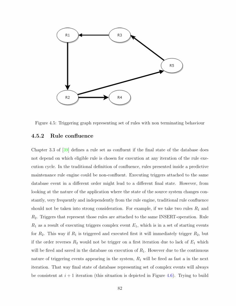
Figure 4.5: Triggering graph representing set of rules with non terminating behaviour
4.5.2 Rule confluence
Chapter 3.3 of [39] defines a rule set as confluent if the final state of the database does
not depend on which eligible rule is chosen for execution at any iteration of the rule exe-
cution cycle. In the traditional definition of confluence, rules presented inside a predictive
maintenance rule engine could be non-confluent. Executing triggers attached to the same
database event in a different order might lead to a different final state. However, from
looking at the nature of the application where the state of the source system changes con-
stantly, very frequently and independently from the rule engine, traditional rule confluence
should not be taken into strong consideration. For example, if we take two rules R1 and
R2. Triggers that represent those rules are attached to the same INSERT-operation. Rule
R1 as a result of executing triggers complex event E1, which is in a set of starting events
for R2. This way if R1 is triggered and executed first it will immediately trigger R2, but
if the order reverses R2 would not be trigger on a first iteration due to lack of E1 which
will be fired and saved in the database on execution of R1. However due to the continuous
nature of triggering events appearing in the system, R1 will be fired as fast a in the next
iteration. That way final state of database representing set of complex events will always
be consistent at i + 1 iteration (this situation is depicted in Figure 4.6). Trying to build
82

Figure 4.6: States transitions depending on rules execution order
perfect confluent rule set is not a trivial task and will lead to syntactical limitations for
users when adding new rules to the system. Also current version of MySQL DBMS 8.0.12
does not allow directly change action order for triggers attached to same database event
making implementation of the rule ordering a very challenging task. However, taking into
consideration a very short period of time that every update iteration takes (1 second in the
presented use case study) the presented approach named Deferred Confluence is sufficient
for the use case of predictive maintenance.
4.5.3 State consistency
Analysis of state consistency is rather simple for the rule engine introduced in this thesis
because of the nature of predictive maintenance systems. Relative to vehicle source sys-
tems, predictive maintenance systems act as a passive observer. This is unlike traditional
active rule engines, which could control the system based on a set of rules and changing
the system state during the operational process. This quality of a predictive maintenance
rule engine guarantees that the state of the observable system does not change, regardless
of what rules were used and in what order they were triggered and executed. The only
83

situation where system states can become inconsistent with the rule engine state is after a
repairment event. This is described in section 4.5.5
4.5.4 Concurrent rule processing
Generally, MySQL triggers have a non-concurrent nature. Every trigger is executed in the
same transaction as an operation that the trigger is attached to. If a database operation
has several triggers attached to it, they are executed strictly in the specified order. On one
hand, this approach limits functionality and reduces the possibility of optimization of a rule
engine. On the other hand, it significantly simplifies the analysis of rule confluence and rule
scheduling. One of the options to introduce concurrency and asynchronous processing in a
rule engine application based on active database features is to use the Microsoft SQL Server
Service Broker [36]. However, for the presented use case, installing such a heavy-weight
server application on a gateway that has limited calculation power is irrelevant.
4.5.5 Recovering database after vehicle repair event
During the regular operation, the state of the database that reflects vehicle state changes
based on the values received from the sensor network and is observed continuously by the
rule engine. Obviously, a situation where the database state could become inconsistent with
the vehicle could occur when the vehicle state changes independently from the predictive
maintenance system. In our case, it is in the instance where a vehicle is taken for repairment
after the predictive maintenance system fires some event predictions. During operation,
the rule engine accumulates a complex event that has been fired based on the defined rule
set and sensor streams. By the time the vehicle accumulates enough critical events to
go to maintenance, the rule engine database state is a defined number of complex events
marked as triggered or fired. After repairment, some of these complex events become
irrelevant because sensor reading stream values at such moments do not correspond with
result events in the database. To solve this inconsistency, the presented framework gives
the user the ability to inform the system that the vehicle was under repair and the system
84

reacts appropriately by clearing all corresponding flags. By setting the status of all complex
result events to not fired, this gives opportunity for the rule engine to recalculate its state
based on the current status of the vehicle provided by sensor stream data, thus restoring
the consistency between the database and vehicle system states.
85

Chapter 5
Experiments
The previous chapter introduced the theoretical model for presenting predictive mainte-
nance rules as active database entities. In the last chapter, we presented implemented
example rules and then conducted the experiments on the rule engine. Experiments in-
cluded simulating series of data streams, and each of these series contained corresponding
parameters and values that should trigger specific rules and fire corresponding events de-
fined by maintenance rules. We demonstrated the steps taken during rule execution and
observed the status of the rule engine database at every phase of execution. After all the
experiments were conducted, we estimated the results by checking facts of fired events
and estimating the performance of the rule engine based on the number of simultaneously
processed rules and hardware used for executing the MySQL DBMS.
5.1 Configuration and methodology
Experiments are conducted on the rule engine encapsulated in the MySQL 5.7.23 DBMS
installed on a Raspberry Pi 3 Model B. Raspberry Pi by default utilizes Class 10 SDHC
microSD card as a storage which provides a writing speed of up to 10 MB/s and a reading
speed up to 98 MB/s. We also conducted additional experiments using SSD-drive to see
the difference in performance of the rule engine.
The metrics that we used when conducting experiments include:
86
• Speed of rule execution depending on the rule type and the number of processed rules
• Correctness of rules execution: whether specific set of rules produce expected results
with specific input data values
We use rules provided by STO domain experts as templates for extra test rules by
injecting random values into threshold parameters and monitoring time. We set a heartbeat
of sensor data simulator to 1 second, which means that every second it inserts new sensor
data snapshots into the rule engine.
Because MySQL does not provide any mechanism for debugging triggers, we must
provide our own strategy for tracking rule execution and log fired prediction events. To
estimate the performance, we need to log checkpoints of every triggered rule such as rule
entry point (triggering phase), start of monitoring phase and action firing phase. By
logging all these checkpoints, we will be able to estimate the performance of every rule and
correctness of fired actions.
Another way to estimate the performance is to measure how long it takes to execute
a set of all rules in one iteration. The nature of the database trigger mechanism works in
such a way that all triggers attached to one INSERT event are executed inside the same
transaction. The transaction is committed only after all the triggers complete execution.
So, by acquiring the start and end of a transaction, we can calculate the time of every
iteration, including execution of all active rules. Unfortunately, MySQL does not provide
any special tools for monitoring and logging transactions, thus we need to track it from
outside of the DBMS.
5.2 Experimental data-set
To conduct the first phase of the experiments, we created a nine-dimensional data set of
parameters and values that represent the vehicle operational period from start to full stop.
Based on the knowledge provided from domain experts, we organized parameter values of
the data set in such a way that they were likely to produce prediction events by triggering
and firing a set of example rules.
87

The test data set is streamed from a file directly into corresponding database tables
thereby generating events for triggering rules of the rule engine.
5.3 Rule execution steps
In this section, we demonstrate step by step what happened inside the rule engine when
specific rules were triggered. We set the rule engine to initial state when no rules or events
are in the fired state. We also added five example rules into the active rule set and started
streaming the example value set. At every iteration, we went through the following steps:
1. Data snapshot added to rule engine by using following SQL-command:
1 INSERT INTO ’ senso r s t r eams ’ ( parameter1 , . . . , parameterN )
2 VALUES ( value1 , . . . , valueN ) ;
2. Trigger-entities attached to ’sensor streams’ table are triggered consequentially de-
pending on specified order
3. Every trigger checks its condition part by applying values from current context to
corresponding parameters. If condition is satisfied corresponding procedure is called
(fire an action or start monitoring phase)
5.3.1 Detailed explanation of rule execution
Further, we present how previously presented steps are implemented and executed with a
set of example rules. We take rule 4 for detailed review:
1. Data acquisition module receives external DTC event ’emergency brake’ from j1939-
network.
2. Data acquisition module inserts new record into ’events streams’ table (in our case
we simulate input data streams by directly inserting data into corresponding tables)
88
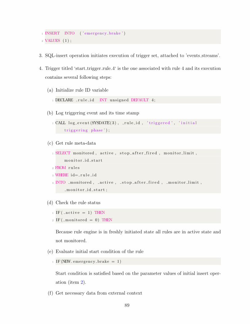
1 INSERT INTO ( ’ emergency brake ’ )
2 VALUES (1) ;
3. SQL-insert operation initiates execution of trigger set, attached to ’events streams’.
4. Trigger titled ‘start trigger rule 4‘ is the one associated with rule 4 and its execution
contains several following steps:
(a) Initialize rule ID variable
1 DECLARE r u l e i d INT unsigned DEFAULT 4 ;
(b) Log triggering event and its time stamp
1 CALL log even t (SYSDATE(3) , r u l e i d , ’ t r i g g e r e d ’ , ’ i n i t i a l
t r i g g e r i n g phase ’ ) ;
(c) Get rule meta-data
1 SELECT monitored , ac t ive , s t o p a f t e r f i r e d , mon i to r l im i t ,
mon i t o r i d s t a r t
2 FROM ru l e s
3 WHERE id= r u l e i d
4 INTO monitored , a c t i v e , s t o p a f t e r f i r e d , mon i t o r l im i t ,
mon i t o r i d s t a r t ;
(d) Check the rule status
1 IF ( a c t i v e = 1) THEN
2 IF ( monitored = 0) THEN
Because rule engine is in freshly initiated state all rules are in active state and
not monitored.
(e) Evaluate initial start condition of the rule
1 IF (NEW. emergency brake = 1)
Start condition is satisfied based on the parameter values of initial insert oper-
ation (item 2).
(f) Get necessary data from external context
89
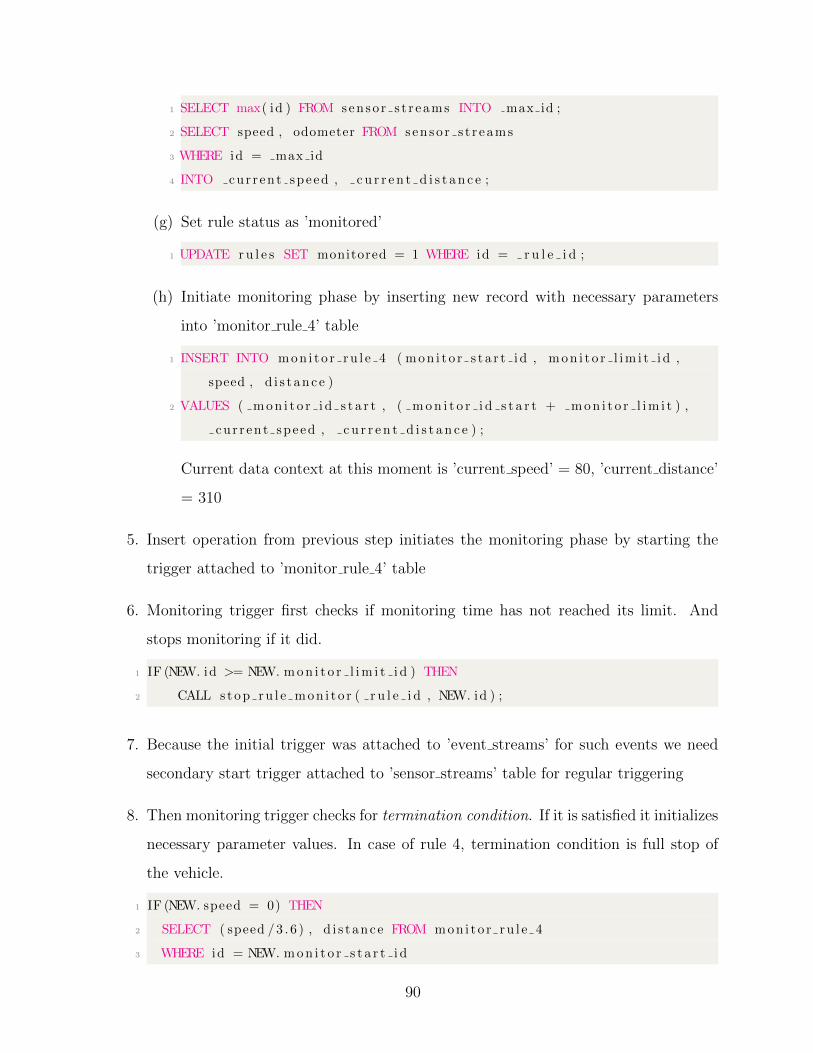
1 SELECT max( id ) FROM senso r s t r eams INTO max id ;
2 SELECT speed , odometer FROM senso r s t r eams
3 WHERE id = max id
4 INTO cur r ent speed , c u r r e n t d i s t a n c e ;
(g) Set rule status as ’monitored’
1 UPDATE ru l e s SET monitored = 1 WHERE id = r u l e i d ;
(h) Initiate monitoring phase by inserting new record with necessary parameters
into ’monitor rule 4’ table
1 INSERT INTO mon i t o r ru l e 4 ( mon i t o r s t a r t i d , mon i t o r l im i t i d ,
speed , d i s t anc e )
2 VALUES ( mon i t o r i d s t a r t , ( mon i t o r i d s t a r t + mon i t o r l im i t ) ,
cu r r ent speed , c u r r e n t d i s t a n c e ) ;
Current data context at this moment is ’current speed’ = 80, ’current distance’
= 310
5. Insert operation from previous step initiates the monitoring phase by starting the
trigger attached to ’monitor rule 4’ table
6. Monitoring trigger first checks if monitoring time has not reached its limit. And
stops monitoring if it did.
1 IF (NEW. id >= NEW. mon i t o r l im i t i d ) THEN
2 CALL s top ru l e mon i t o r ( r u l e i d , NEW. id ) ;
7. Because the initial trigger was attached to ’event streams’ for such events we need
secondary start trigger attached to ’sensor streams’ table for regular triggering
8. Then monitoring trigger checks for termination condition. If it is satisfied it initializes
necessary parameter values. In case of rule 4, termination condition is full stop of
the vehicle.
1 IF (NEW. speed = 0) THEN
2 SELECT ( speed /3 . 6 ) , d i s t anc e FROM mon i to r ru l e 4
3 WHERE id = NEW. mon i t o r s t a r t i d
90
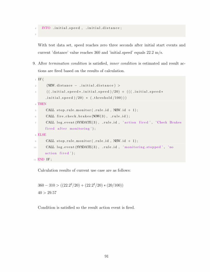
4 INTO i n i t i a l s p e e d , i n i t i a l d i s t a n c e ;
5
With test data set, speed reaches zero three seconds after initial start events and
current ’distance’ value reaches 360 and ’initial speed’ equals 22.2 m/s.
9. After termination condition is satisfied, inner condition is estimated and result ac-
tions are fired based on the results of calculation.
1 IF (
2 (NEW. d i s t anc e − i n i t i a l d i s t a n c e ) >
3 ( ( i n i t i a l s p e e d ∗ i n i t i a l s p e e d ) /20) + ( ( ( i n i t i a l s p e e d ∗
i n i t i a l s p e e d ) /20) ∗ ( t h r e sho l d /100) ) )
4 THEN
5 CALL s top ru l e mon i t o r ( r u l e i d , NEW. id + 1) ;
6 CALL f i r e c h e c k b r a k e s (NOW(3) , r u l e i d ) ;
7 CALL log even t (SYSDATE(3) , r u l e i d , ’ a c t i on f i r e d ’ , ’ Check Brakes
f i r e d a f t e r monitor ing ’ ) ;
8 ELSE
9 CALL s top ru l e mon i t o r ( r u l e i d , NEW. id + 1) ;
10 CALL log even t (SYSDATE(3) , r u l e i d , ’ monitor ing stopped ’ , ’ no
ac t i on f i r e d ’ ) ;
11 END IF ;
Calculation results of current use case are as follows:
360− 310 > ((22.22/20) + (22.22/20) ∗ (20/100))
40 > 29.57
Condition is satisfied so the result action event is fired.
91
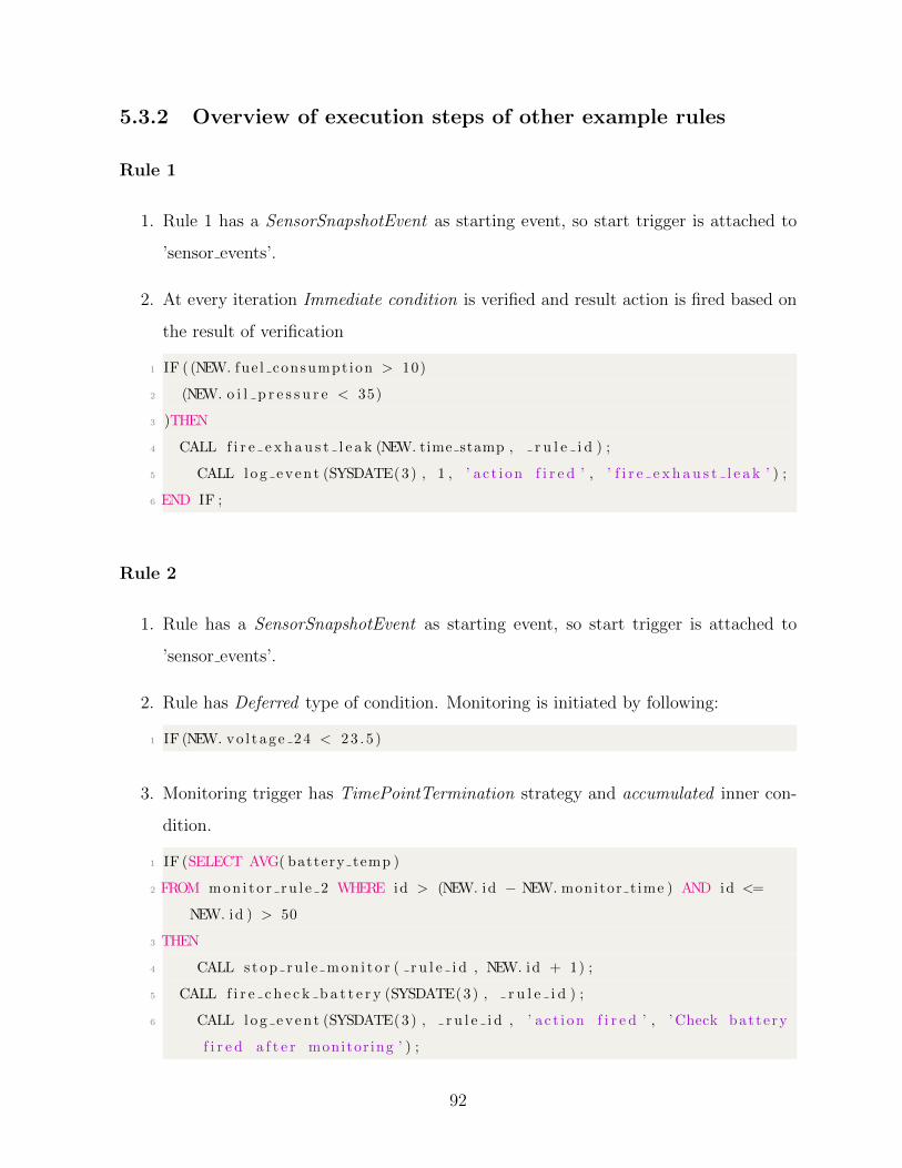
5.3.2 Overview of execution steps of other example rules
Rule 1
1. Rule 1 has a SensorSnapshotEvent as starting event, so start trigger is attached to
’sensor events’.
2. At every iteration Immediate condition is verified and result action is fired based on
the result of verification
1 IF ( (NEW. fue l consumpt ion > 10)
2 (NEW. o i l p r e s s u r e < 35)
3 )THEN
4 CALL f i r e e x h a u s t l e a k (NEW. time stamp , r u l e i d ) ;
5 CALL log even t (SYSDATE(3) , 1 , ’ a c t i on f i r e d ’ , ’ f i r e e x h a u s t l e a k ’ ) ;
6 END IF ;
Rule 2
1. Rule has a SensorSnapshotEvent as starting event, so start trigger is attached to
’sensor events’.
2. Rule has Deferred type of condition. Monitoring is initiated by following:
1 IF (NEW. vo l t age 24 < 23 . 5 )
3. Monitoring trigger has TimePointTermination strategy and accumulated inner con-
dition.
1 IF (SELECT AVG( battery temp )
2 FROM mon i t o r ru l e 2 WHERE id > (NEW. id − NEW. monitor t ime ) AND id <=
NEW. id ) > 50
3 THEN
4 CALL s top ru l e mon i t o r ( r u l e i d , NEW. id + 1) ;
5 CALL f i r e c h e c k b a t t e r y (SYSDATE(3) , r u l e i d ) ;
6 CALL log even t (SYSDATE(3) , r u l e i d , ’ a c t i on f i r e d ’ , ’ Check batte ry
f i r e d a f t e r monitor ing ’ ) ;
92

7 ELSE
8 CALL s top ru l e mon i t o r ( r u l e i d , NEW. id + 1) ;
9 CALL log even t (SYSDATE(3) , r u l e i d , ’ monitor ing stopped ’ , ’ Rule 2
monitor ing stopped without ac t i on ’ ) ;
10 END IF ;
Rule 3
1. Rule has a SensorSnapshotEvent as starting event, so start trigger is attached to
’sensor events’.
2. Rule has Deferred type of condition. Monitoring is initiated by following:
1 IF (NEW. coolant temp > 211)
2
3. Monitoring trigger has ConditionalTermination strategy and immediate inner condi-
tion with external data context.
1 IF (NEW. id >= NEW. mon i t o r l im i t i d ) THEN
2 CALL s top ru l e mon i t o r ( r u l e i d , NEW. id ) ;
3 CALL log even t (SYSDATE(3) , r u l e i d , ’ monitor stopped ’ , ’ Rule 4
monitor ing stopped without ac t i on ’ ) ;
4 ELSE
5 SELECT t r i g g e r e d FROM r e s u l t e v e n t s WHERE t e x t i d = ”
transmis s i on warn ing ” INTO transmi s s i on warn ing ;
6 IF ( t ransmi s s i on warn ing = 1) THEN
7 CALL s top ru l e mon i t o r ( r u l e i d , NEW. id + 1) ;
8 CALL f i r e c h e c k b e l t (SYSDATE(3) , r u l e i d ) ;
9 CALL log even t (SYSDATE(3) , r u l e i d , ’ a c t i on f i r e d ’ , ’ Check
Belt f i r e d a f t e r monitor ing ’ ) ;
10 END IF ;
11 END IF ;
93

Rule 5
1. Rule has a SensorSnapshotEvent as starting event, so start trigger is attached to
’sensor events’.
2. Rule has Accumulated type of condition. With AVG reduce function.
1 IF ( SELECT AVG( coo l an t p r e s s u r e )
2 FROM senso r s t r eams
3 WHERE id > (NEW. id − accumulate t ime )
4 AND id <= NEW. id ) > (NEW. coo l an t p r e s s u r e + th r e sho l d )
5 THEN
6 CALL f i r e c o o l a n t l e a k (SYSDATE(3) , r u l e i d ) ;
7 CALL log even t (SYSDATE(3) , 1 , ’ a c t i on f i r e d ’ , ’ c o o l an t l e a k ’ ) ;
8 END IF ;
Results of rule execution are presented by events time-line and is depicted in Figure 5.1
5.4 Performance evaluation
In this section, we stream the presented dataset into the rule engine containing different
amount and classes of rules and demonstrate how those changes affect the performance
and effectiveness of rule execution.
5.4.1 Rule classes comparison (30 rules)
Figure 5.2 depicts how average execution time varies for different rule classes. We used set
of 30 rules and about 1000 iterations.
5.4.2 Mixed class rule set (5 rules)
Here we measured (Figure 5.3) the rule engine performance for five example rules executed
both on the Raspberry Pi and PC. Rule execution timings are significantly lower on PC but
are still satisfactory on Raspberry Pi and do not exceed 80 milliseconds for one iteration.
94
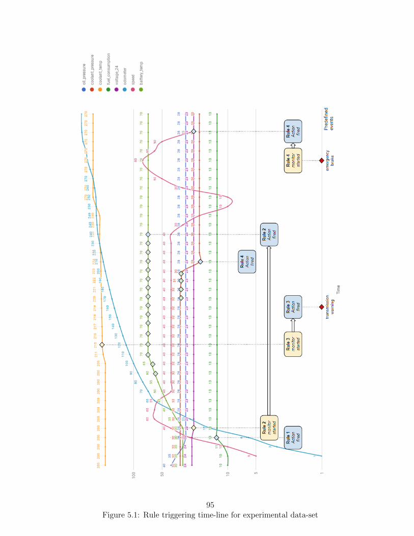
Figure 5.1: Rule triggering time-line for experimental data-set95
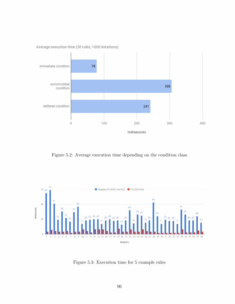
Figure 5.2: Average execution time depending on the condition class
Figure 5.3: Execution time for 5 example rules
96
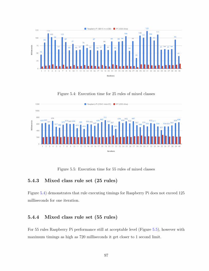
Figure 5.4: Execution time for 25 rules of mixed classes
Figure 5.5: Execution time for 55 rules of mixed classes
5.4.3 Mixed class rule set (25 rules)
Figure 5.4) demonstrates that rule executing timings for Raspberry Pi does not exceed 125
milliseconds for one iteration.
5.4.4 Mixed class rule set (55 rules)
For 55 rules Raspberry Pi performance still at acceptable level (Figure 5.5), however with
maximum timings as high as 720 milliseconds it get closer to 1 second limit.
97
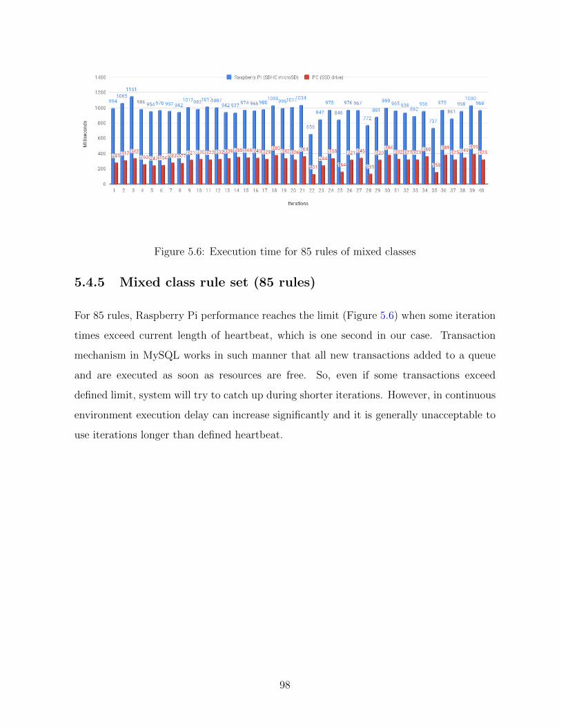
Figure 5.6: Execution time for 85 rules of mixed classes
5.4.5 Mixed class rule set (85 rules)
For 85 rules, Raspberry Pi performance reaches the limit (Figure 5.6) when some iteration
times exceed current length of heartbeat, which is one second in our case. Transaction
mechanism in MySQL works in such manner that all new transactions added to a queue
and are executed as soon as resources are free. So, even if some transactions exceed
defined limit, system will try to catch up during shorter iterations. However, in continuous
environment execution delay can increase significantly and it is generally unacceptable to
use iterations longer than defined heartbeat.
98
Chapter 6
Conclusion and Future work
6.1 Conclusion
The idea of using predictive maintenance in the automotive industry is becoming increas-
ingly standard for many companies. This thesis proposed steps for integrating predictive
maintenance functionality into the fleet management system. Based on industry require-
ments, we developed and modeled the architecture of an FMS and the interaction between
its components using traditional UML notations and its extensions for embedded systems
such as SysML and MARTE. As a result, we presented a set of diagrams that could be
used for implementing the final solution.
Additionally, we conducted extensive research on various predictive maintenance ap-
proaches. Ultimately, we decided to use a knowledge-driven approach to implement the
rule engine on the gateway module of the FMS. To achieve this, we acquired domain
knowledge by conducting a series of interviews with domain experts and organized it into
business rules. The following step became the main contribution of this thesis. To make
use of the acquired business rules inside the FMS rule engine, it was necessary to determine
a technique for transferring human knowledge into active rules. Because one of the pre-
requirements was to implement rule event detection on the edge gateway device, we used
a Raspberry Pi portable computer as a gateway platform. Since Raspberry Pi is limited
in its computational power, we decided to encapsulate the rule engine inside the MySQL
99

DBMS using active database features. To achieve this, we developed a methodology for
converting domain knowledge into active database entities. Our solution was inspired by
the IDEA methodology in that rules are mapped to software classes and later to active
database entities. As a result, we designed abstract rule definitions that gave us a sufficient
level of flexibility to store a wide variety of rules created by domain experts. At the same
time, the software engineering approaches that we used to design rule class entity allowed
us to provide scalability for extending possible rule definitions in the future.
During the process of developing the rule engine, we encountered several problems
that are traditionally associated with utilizing active rules, such as rule termination, rule
confluence and consistency of database states. To overcome these challenges, we used the
solutions described in the literature [39], such as building a triggering graph to solve the
rule termination problem and presenting the idea of deferred confluence used for predictive
maintenance rules in our rule engine.
Lastly, we conducted a series of experiments to verify the correctness of rule execution
and estimate how the performance depends on a number of simultaneously processed rules
and on rule types. We accomplished this by injecting different sets of rules into the rule
engine and then simulating the functionality of the data acquisition module by streaming
sensor network data into the database.
The experiment results demonstrated that the rules that were generated using the
proposed methodology successfully produced the expected outcome firing of action events
based on the observed status of the vehicle. We also estimated the performance of the rule
engine and can conclude that it demonstrated acceptable results on Raspberry Pi when
the maximum amount of simultaneously processed rules did not exceed 70 for mixed-type
rules, and 110 for rules containing only simple immediate conditions. These assumptions
were made based on the pre-condition that one iteration or streaming heartbeat should
not exceed one second.
100
6.2 Directions for future work
Before finalizing this report, we would like to present directions for future works that will
focus on improving the functionality, stability and performance of the system:
• Concurrent rule processing : using database management systems that support run-
ning inner procedures in background threads may give us the ability to increase
performance and eliminate the problem of sequential rule execution. One possible
solution is to use MSSQL DBMS, however it will require the use of a more powerful
platform for gateway implementation.
• Testing in the real working environment : this would entail implementation of the
FMS architecture to operate within the real working cycle of a STO-company. It
includes installing a gateway device on the bus and connecting it to the sensor net-
work for accumulating data, deploying server infrastructure and connecting gateway
devices to SLN for captured data and events. We can also test the performance of
the rule engine in the context of working with real continuous data.
• Implementing self-learning techniques : rule engines implemented using knowledge-
based approaches are steady and reliable; however, they are limited by the knowledge
provided by domain experts and do not have the ability to extend the knowledge
base automatically without human intervention. Thus, another proposed direction
for future work is an attempt to implement machine learning approaches like the one
presented in [44]. After the gateway module accumulates sufficient data about its
operational cycles and states, we will be able to estimate how efficient and effective
such approaches could be.
101

APPENDICES
102
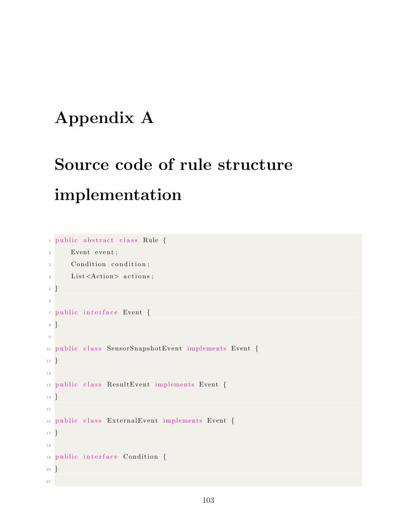
Appendix A
Source code of rule structure
implementation
1 pub l i c ab s t r a c t c l a s s Rule {
2 Event event ;
3 Condit ion cond i t i on ;
4 List<Action> a c t i on s ;
5 }
6
7 pub l i c i n t e r f a c e Event {
8 }
9
10 pub l i c c l a s s SensorSnapshotEvent implements Event {
11 }
12
13 pub l i c c l a s s ResultEvent implements Event {
14 }
15
16 pub l i c c l a s s ExternalEvent implements Event {
17 }
18
19 pub l i c i n t e r f a c e Condit ion {
20 }
21
103
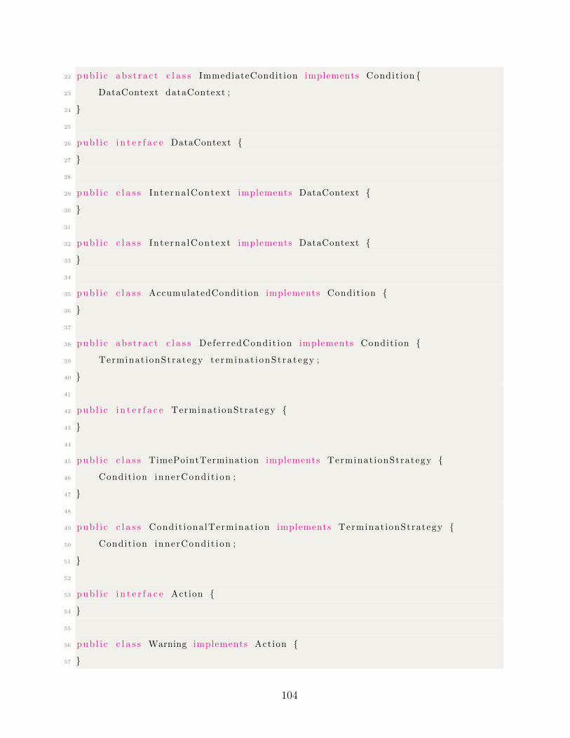
22 pub l i c ab s t r a c t c l a s s ImmediateCondition implements Condit ion {
23 DataContext dataContext ;
24 }
25
26 pub l i c i n t e r f a c e DataContext {
27 }
28
29 pub l i c c l a s s Inte rna lContext implements DataContext {
30 }
31
32 pub l i c c l a s s Inte rna lContext implements DataContext {
33 }
34
35 pub l i c c l a s s AccumulatedCondition implements Condit ion {
36 }
37
38 pub l i c ab s t r a c t c l a s s DeferredCondit ion implements Condit ion {
39 Terminat ionStrategy te rminat ionSt ra tegy ;
40 }
41
42 pub l i c i n t e r f a c e Terminat ionStrategy {
43 }
44
45 pub l i c c l a s s TimePointTermination implements Terminat ionStrategy {
46 Condit ion innerCondi t ion ;
47 }
48
49 pub l i c c l a s s Condit ionalTerminat ion implements Terminat ionStrategy {
50 Condit ion innerCondi t ion ;
51 }
52
53 pub l i c i n t e r f a c e Action {
54 }
55
56 pub l i c c l a s s Warning implements Action {
57 }
104

58
59 pub l i c c l a s s Warning implements Action {
60 }
61
62 pub l i c c l a s s RealTime implements Action {
63 }
105
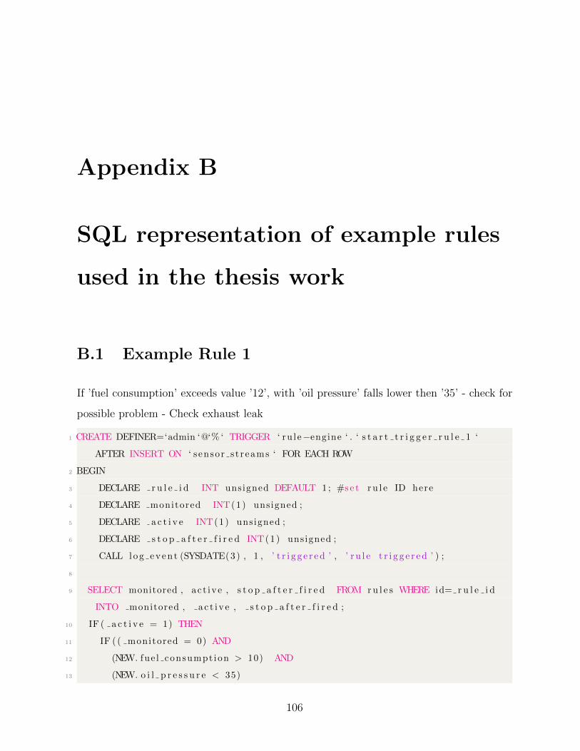
Appendix B
SQL representation of example rules
used in the thesis work
B.1 Example Rule 1
If ’fuel consumption’ exceeds value ’12’, with ’oil pressure’ falls lower then ’35’ - check for
possible problem - Check exhaust leak
1 CREATE DEFINER=‘admin ‘@‘% ‘ TRIGGER ‘ ru le−engine ‘ . ‘ s t a r t t r i g g e r r u l e 1 ‘
AFTER INSERT ON ‘ sensor s t reams ‘ FOR EACH ROW
2 BEGIN
3 DECLARE r u l e i d INT unsigned DEFAULT 1 ; #se t r u l e ID here
4 DECLARE monitored INT(1) unsigned ;
5 DECLARE a c t i v e INT(1) unsigned ;
6 DECLARE s t o p a f t e r f i r e d INT(1) unsigned ;
7 CALL log even t (SYSDATE(3) , 1 , ’ t r i g g e r e d ’ , ’ r u l e t r i g g e r e d ’ ) ;
8
9 SELECT monitored , ac t ive , s t o p a f t e r f i r e d FROM ru l e s WHERE id= r u l e i d
INTO monitored , a c t i v e , s t o p a f t e r f i r e d ;
10 IF ( a c t i v e = 1) THEN
11 IF ( ( monitored = 0) AND
12 (NEW. fue l consumpt ion > 10) AND
13 (NEW. o i l p r e s s u r e < 35)
106
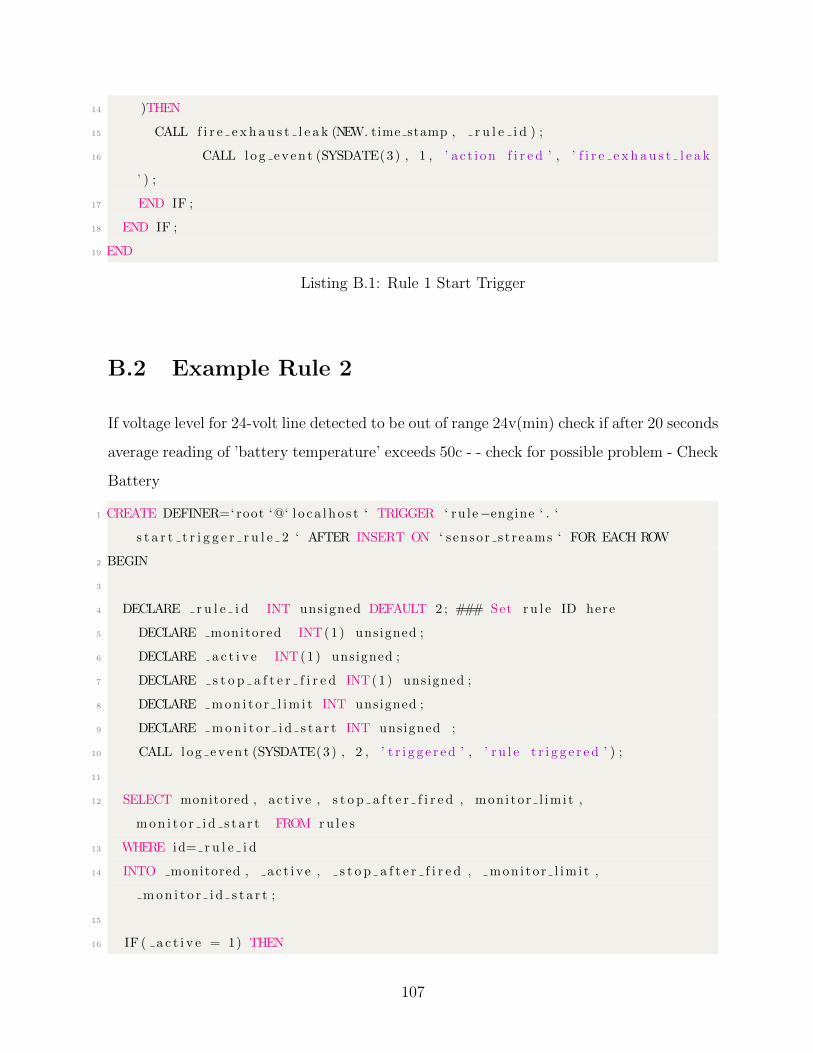
14 )THEN
15 CALL f i r e e x h a u s t l e a k (NEW. time stamp , r u l e i d ) ;
16 CALL log even t (SYSDATE(3) , 1 , ’ a c t i on f i r e d ’ , ’ f i r e e x h a u s t l e a k
’ ) ;
17 END IF ;
18 END IF ;
19 END
Listing B.1: Rule 1 Start Trigger
B.2 Example Rule 2
If voltage level for 24-volt line detected to be out of range 24v(min) check if after 20 seconds
average reading of ’battery temperature’ exceeds 50c - - check for possible problem - Check
Battery
1 CREATE DEFINER=‘ root ‘@‘ l o c a l ho s t ‘ TRIGGER ‘ ru le−engine ‘ . ‘
s t a r t t r i g g e r r u l e 2 ‘ AFTER INSERT ON ‘ sensor s t reams ‘ FOR EACH ROW
2 BEGIN
3
4 DECLARE r u l e i d INT unsigned DEFAULT 2 ; ### Set ru l e ID here
5 DECLARE monitored INT(1) unsigned ;
6 DECLARE a c t i v e INT(1) unsigned ;
7 DECLARE s t o p a f t e r f i r e d INT(1) unsigned ;
8 DECLARE mon i t o r l im i t INT unsigned ;
9 DECLARE mon i t o r i d s t a r t INT unsigned ;
10 CALL log even t (SYSDATE(3) , 2 , ’ t r i g g e r e d ’ , ’ r u l e t r i g g e r e d ’ ) ;
11
12 SELECT monitored , ac t ive , s t o p a f t e r f i r e d , mon i to r l im i t ,
mon i t o r i d s t a r t FROM ru l e s
13 WHERE id= r u l e i d
14 INTO monitored , a c t i v e , s t o p a f t e r f i r e d , mon i t o r l im i t ,
mon i t o r i d s t a r t ;
15
16 IF ( a c t i v e = 1) THEN
107

17 IF ( monitored = 0) THEN
18 IF (NEW. vo l t age 24 < 24) THEN ### Set vo l tage t r e sho l d here
19 UPDATE ru l e s SET monitored = 1 WHERE id = r u l e i d ;
20 CALL log even t (SYSDATE(3) , 2 , ’ monitor s t a r t ed ’ , ’ s t a r t
monitor ing ru l e 2 ’ ) ;
21 CALL mon i t o r ru l e 2 (NEW. battery temp , ( mon i t o r i d s t a r t +
mon i t o r l im i t ) ) ;
22 END IF ;
23 ELSE
24 CALL mon i t o r ru l e 2 (NEW. battery temp , ( mon i t o r i d s t a r t +
mon i t o r l im i t ) ) ;
25 END IF ;
26 END IF ;
27 END
Listing B.2: Rule 2 Start Trigger
1 CREATE DEFINER=‘ root ‘@‘ l o c a l ho s t ‘ TRIGGER ‘ ru le−engine ‘ . ‘ mon i to r ru l e 2 ‘
AFTER INSERT ON ‘ mon i to r ru l e 2 ‘ FOR EACH ROW
2 BEGIN
3 DECLARE r u l e i d INT unsigned DEFAULT 2 ; #se t r u l e ID here
4 IF (NEW. id >= NEW. mon i t o r l im i t i d ) THEN
5 IF (SELECT AVG( battery temp ) FROM mon i to r ru l e 2 WHERE id > (NEW. id − NEW
. monitor t ime ) AND id <= NEW. id ) > 50 THEN
6 CALL s top ru l e mon i t o r ( r u l e i d , NEW. id + 1) ;
7 CALL f i r e c h e c k b a t t e r y (SYSDATE(3) , r u l e i d ) ;
8 CALL log even t (SYSDATE(3) , r u l e i d , ’ a c t i on f i r e d ’ , ’ Check
batte ry f i r e d a f t e r monitor ing ’ ) ;
9 ELSE
10 CALL s top ru l e mon i t o r ( r u l e i d , NEW. id + 1) ;
11 CALL log even t (SYSDATE(3) , r u l e i d , ’ monitor stopped ’ , ’ Rule 2
monitor ing stopped without ac t i on ’ ) ;
12 END IF ;
13 END IF ;
14 END
Listing B.3: Rule 2 Monitor Trigger
108
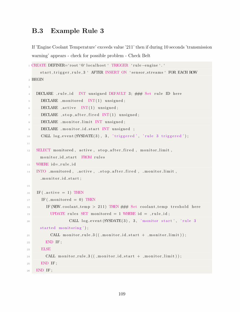
B.3 Example Rule 3
If ’Engine Coolant Temperature’ exceeds value ’211’ then if during 10 seconds ’transmission
warning’ appears - check for possible problem - Check Belt
1 CREATE DEFINER=‘ root ‘@‘ l o c a l ho s t ‘ TRIGGER ‘ ru le−engine ‘ . ‘
s t a r t t r i g g e r r u l e 3 ‘ AFTER INSERT ON ‘ sensor s t reams ‘ FOR EACH ROW
2 BEGIN
3
4 DECLARE r u l e i d INT unsigned DEFAULT 3 ; ### Set ru l e ID here
5 DECLARE monitored INT(1) unsigned ;
6 DECLARE a c t i v e INT(1) unsigned ;
7 DECLARE s t o p a f t e r f i r e d INT(1) unsigned ;
8 DECLARE mon i t o r l im i t INT unsigned ;
9 DECLARE mon i t o r i d s t a r t INT unsigned ;
10 CALL log even t (SYSDATE(3) , 3 , ’ t r i g g e r e d ’ , ’ r u l e 3 t r i g g e r e d ’ ) ;
11
12 SELECT monitored , ac t ive , s t o p a f t e r f i r e d , mon i to r l im i t ,
mon i t o r i d s t a r t FROM ru l e s
13 WHERE id= r u l e i d
14 INTO monitored , a c t i v e , s t o p a f t e r f i r e d , mon i t o r l im i t ,
mon i t o r i d s t a r t ;
15
16 IF ( a c t i v e = 1) THEN
17 IF ( monitored = 0) THEN
18 IF (NEW. coolant temp > 211) THEN ### Set coolant temp t r e sho l d here
19 UPDATE ru l e s SET monitored = 1 WHERE id = r u l e i d ;
20 CALL log even t (SYSDATE(3) , 3 , ’ monitor s t a r t ’ , ’ r u l e 3
s t a r t ed monitor ing ’ ) ;
21 CALL mon i t o r ru l e 3 ( ( mon i t o r i d s t a r t + mon i t o r l im i t ) ) ;
22 END IF ;
23 ELSE
24 CALL mon i t o r ru l e 3 ( ( mon i t o r i d s t a r t + mon i t o r l im i t ) ) ;
25 END IF ;
26 END IF ;
109

27 END
Listing B.4: Rule 3 Start Trigger
1 CREATE DEFINER=‘ root ‘@‘ l o c a l ho s t ‘ TRIGGER ‘ ru le−engine ‘ . ‘ mon i to r ru l e 3 ‘
AFTER INSERT ON ‘ mon i to r ru l e 3 ‘ FOR EACH ROW
2 BEGIN
3 DECLARE r u l e i d INT unsigned DEFAULT 3 ; #se t r u l e ID here
4 DECLARE transmi s s i on warn ing INT unsigned DEFAULT 0 ;
5 IF (NEW. id >= NEW. mon i t o r l im i t i d ) THEN
6 CALL s top ru l e mon i t o r ( r u l e i d , NEW. id ) ;
7 CALL log even t (SYSDATE(3) , r u l e i d , ’ monitor stopped ’ , ’ Rule 4
monitor ing stopped without ac t i on ’ ) ;
8 ELSE
9 SELECT t r i g g e r e d FROM r e s u l t e v e n t s WHERE t e x t i d = ”
transmis s i on warn ing ” INTO transmi s s i on warn ing ;
10 IF ( t ransmi s s i on warn ing = 1) THEN
11 CALL s top ru l e mon i t o r ( r u l e i d , NEW. id + 1) ;
12 CALL f i r e c h e c k b e l t (SYSDATE(3) , r u l e i d ) ;
13 CALL log even t (SYSDATE(3) , r u l e i d , ’ a c t i on f i r e d ’ , ’ Check Belt
f i r e d a f t e r monitor ing ’ ) ;
14 END IF ;
15 END IF ;
16 END
Listing B.5: Rule 3 Monitor Trigger
B.4 Example Rule 4
After ’emergency break’ external event, monitor for 10 seconds, if speed reaches 0 - check
the stopping distance. If it exceeds norm (norm is calculated using formula specified in
[7]) by 20% then - check for possible problem - Braking system
1 CREATE DEFINER=‘ root ‘@‘ l o c a l ho s t ‘ TRIGGER ‘ ru le−engine ‘ . ‘
s t a r t t r i g g e r r u l e 4 ‘ AFTER INSERT ON ‘ events s t reams ‘ FOR EACH ROW
2 BEGIN
110
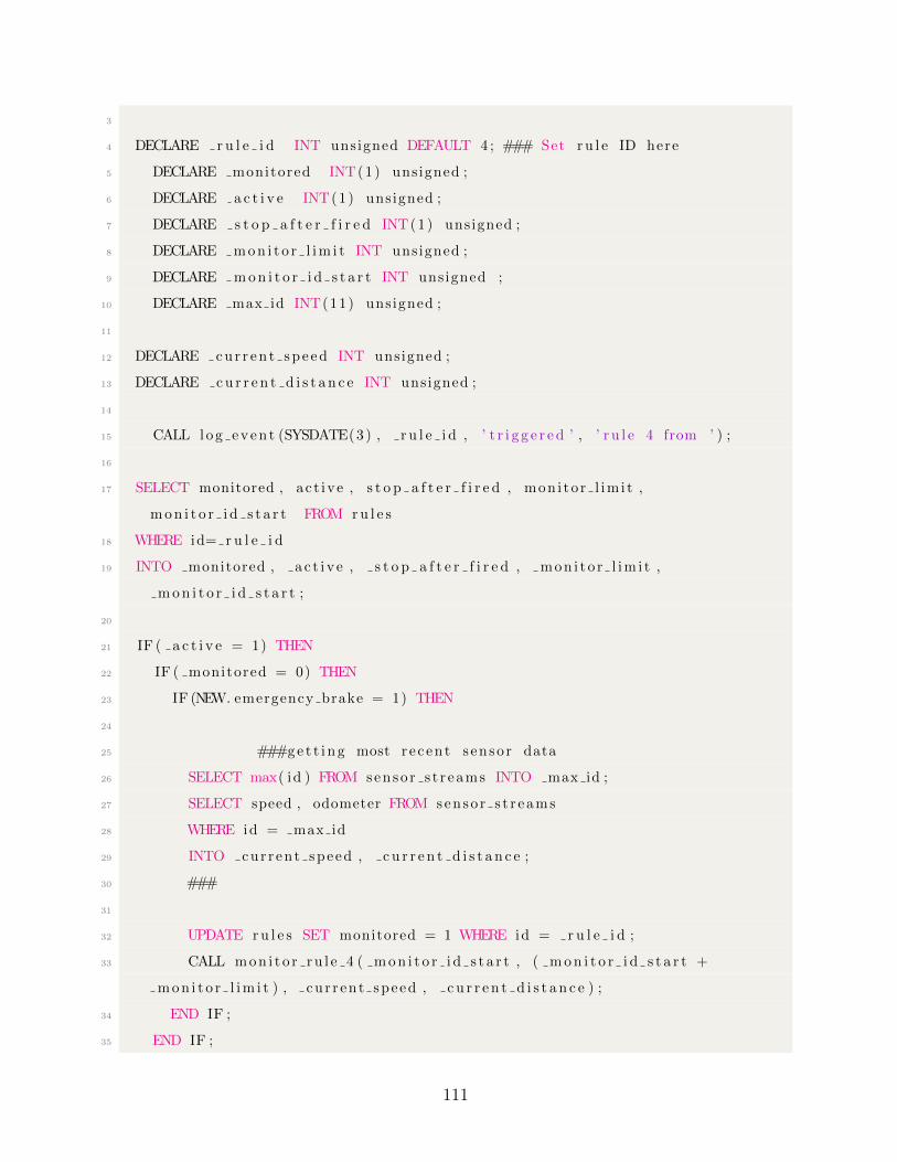
3
4 DECLARE r u l e i d INT unsigned DEFAULT 4 ; ### Set ru l e ID here
5 DECLARE monitored INT(1) unsigned ;
6 DECLARE a c t i v e INT(1) unsigned ;
7 DECLARE s t o p a f t e r f i r e d INT(1) unsigned ;
8 DECLARE mon i t o r l im i t INT unsigned ;
9 DECLARE mon i t o r i d s t a r t INT unsigned ;
10 DECLARE max id INT(11) unsigned ;
11
12 DECLARE cur r en t sp e ed INT unsigned ;
13 DECLARE cu r r e n t d i s t a n c e INT unsigned ;
14
15 CALL log even t (SYSDATE(3) , r u l e i d , ’ t r i g g e r e d ’ , ’ r u l e 4 from ’ ) ;
16
17 SELECT monitored , ac t ive , s t o p a f t e r f i r e d , mon i to r l im i t ,
mon i t o r i d s t a r t FROM ru l e s
18 WHERE id= r u l e i d
19 INTO monitored , a c t i v e , s t o p a f t e r f i r e d , mon i t o r l im i t ,
mon i t o r i d s t a r t ;
20
21 IF ( a c t i v e = 1) THEN
22 IF ( monitored = 0) THEN
23 IF (NEW. emergency brake = 1) THEN
24
25 ###ge t t i ng most r e c ent s enso r data
26 SELECT max( id ) FROM senso r s t r eams INTO max id ;
27 SELECT speed , odometer FROM senso r s t r eams
28 WHERE id = max id
29 INTO cur r ent speed , c u r r e n t d i s t a n c e ;
30 ###
31
32 UPDATE ru l e s SET monitored = 1 WHERE id = r u l e i d ;
33 CALL mon i t o r ru l e 4 ( mon i t o r i d s t a r t , ( mon i t o r i d s t a r t +
mon i t o r l im i t ) , cu r r ent speed , c u r r e n t d i s t a n c e ) ;
34 END IF ;
35 END IF ;
111
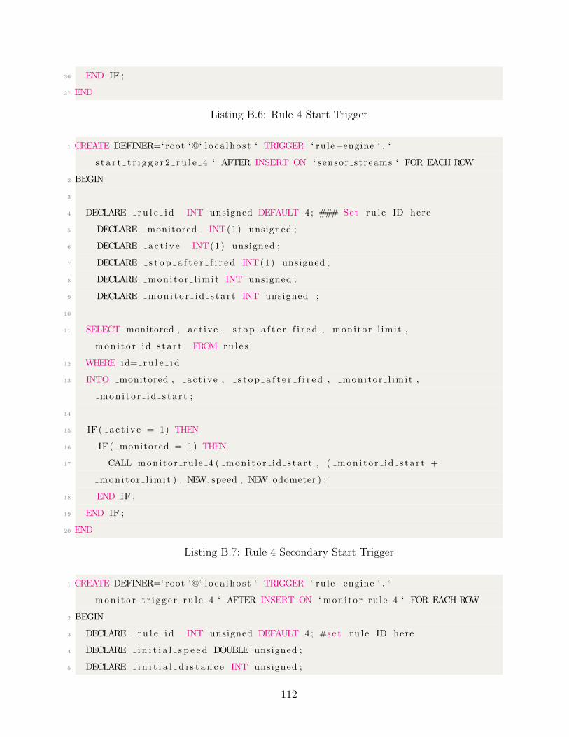
36 END IF ;
37 END
Listing B.6: Rule 4 Start Trigger
1 CREATE DEFINER=‘ root ‘@‘ l o c a l ho s t ‘ TRIGGER ‘ ru le−engine ‘ . ‘
s t a r t t r i g g e r 2 r u l e 4 ‘ AFTER INSERT ON ‘ sensor s t reams ‘ FOR EACH ROW
2 BEGIN
3
4 DECLARE r u l e i d INT unsigned DEFAULT 4 ; ### Set ru l e ID here
5 DECLARE monitored INT(1) unsigned ;
6 DECLARE a c t i v e INT(1) unsigned ;
7 DECLARE s t o p a f t e r f i r e d INT(1) unsigned ;
8 DECLARE mon i t o r l im i t INT unsigned ;
9 DECLARE mon i t o r i d s t a r t INT unsigned ;
10
11 SELECT monitored , ac t ive , s t o p a f t e r f i r e d , mon i to r l im i t ,
mon i t o r i d s t a r t FROM ru l e s
12 WHERE id= r u l e i d
13 INTO monitored , a c t i v e , s t o p a f t e r f i r e d , mon i t o r l im i t ,
mon i t o r i d s t a r t ;
14
15 IF ( a c t i v e = 1) THEN
16 IF ( monitored = 1) THEN
17 CALL mon i t o r ru l e 4 ( mon i t o r i d s t a r t , ( mon i t o r i d s t a r t +
mon i t o r l im i t ) , NEW. speed , NEW. odometer ) ;
18 END IF ;
19 END IF ;
20 END
Listing B.7: Rule 4 Secondary Start Trigger
1 CREATE DEFINER=‘ root ‘@‘ l o c a l ho s t ‘ TRIGGER ‘ ru le−engine ‘ . ‘
mon i t o r t r i g g e r r u l e 4 ‘ AFTER INSERT ON ‘ mon i to r ru l e 4 ‘ FOR EACH ROW
2 BEGIN
3 DECLARE r u l e i d INT unsigned DEFAULT 4 ; #se t r u l e ID here
4 DECLARE i n i t i a l s p e e d DOUBLE unsigned ;
5 DECLARE i n i t i a l d i s t a n c e INT unsigned ;
112

6
7 IF (NEW. id >= NEW. mon i t o r l im i t i d ) THEN
8 CALL s top ru l e mon i t o r ( r u l e i d , NEW. id ) ;
9 ELSE
10 IF (NEW. speed = 0) THEN
11
12 SELECT ( speed /3 . 6 ) , d i s t anc e FROM mon i to r ru l e 4
13 WHERE id = NEW. mon i t o r s t a r t i d
14 INTO i n i t i a l s p e e d , i n i t i a l d i s t a n c e ;
15
16 IF ( (NEW. d i s t ance − i n i t i a l d i s t a n c e ) > ( ( i n i t i a l s p e e d ∗
i n i t i a l s p e e d ) /20) ) THEN
17 CALL s top ru l e mon i t o r ( r u l e i d , NEW. id + 1) ;
18 CALL f i r e c h e c k b r a k e s (NOW(3) , r u l e i d ) ;
19 CALL log even t (SYSDATE(3) , r u l e i d , ’ a c t i on f i r e d ’ , ’ Check
Brakes f i r e d a f t e r monitor ing ’ ) ;
20 ELSE
21 CALL s top ru l e mon i t o r ( r u l e i d , NEW. id + 1) ;
22 CALL log even t (SYSDATE(3) , r u l e i d , ’ a c t i on f i r e d ’ , ’ Check
Belt f i r e d a f t e r monitor ing ’ ) ;
23 END IF ;
24 END IF ;
25 END IF ;
26 END
Listing B.8: Rule 4 Monitor Trigger
B.5 Example Rule 5
If ’coolant pressure’ drops by 20% comparing to the average value acquired for last 5
seconds then - check for possible problem - Check for coolant leak
1 CREATE DEFINER=‘admin ‘@‘% ‘ TRIGGER ‘ ru le−engine ‘ . ‘ s t a r t t r i g g e r r u l e 5 ‘
AFTER INSERT ON ‘ sensor s t reams ‘ FOR EACH ROW
2 BEGIN
3
113
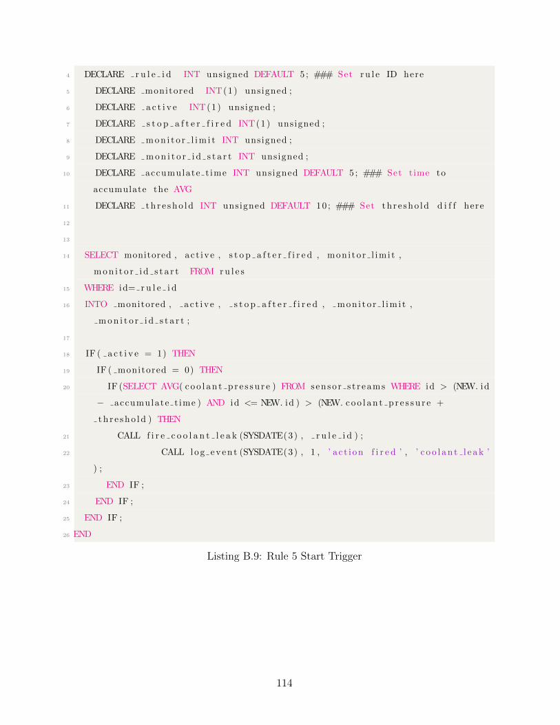
4 DECLARE r u l e i d INT unsigned DEFAULT 5 ; ### Set ru l e ID here
5 DECLARE monitored INT(1) unsigned ;
6 DECLARE a c t i v e INT(1) unsigned ;
7 DECLARE s t o p a f t e r f i r e d INT(1) unsigned ;
8 DECLARE mon i t o r l im i t INT unsigned ;
9 DECLARE mon i t o r i d s t a r t INT unsigned ;
10 DECLARE accumulate t ime INT unsigned DEFAULT 5 ; ### Set time to
accumulate the AVG
11 DECLARE th r e sho l d INT unsigned DEFAULT 10 ; ### Set th r e sho ld d i f f here
12
13
14 SELECT monitored , ac t ive , s t o p a f t e r f i r e d , mon i to r l im i t ,
mon i t o r i d s t a r t FROM ru l e s
15 WHERE id= r u l e i d
16 INTO monitored , a c t i v e , s t o p a f t e r f i r e d , mon i t o r l im i t ,
mon i t o r i d s t a r t ;
17
18 IF ( a c t i v e = 1) THEN
19 IF ( monitored = 0) THEN
20 IF (SELECT AVG( coo l an t p r e s s u r e ) FROM senso r s t r eams WHERE id > (NEW. id
− accumulate t ime ) AND id <= NEW. id ) > (NEW. coo l an t p r e s s u r e +
th r e sho l d ) THEN
21 CALL f i r e c o o l a n t l e a k (SYSDATE(3) , r u l e i d ) ;
22 CALL log even t (SYSDATE(3) , 1 , ’ a c t i on f i r e d ’ , ’ c o o l an t l e a k ’
) ;
23 END IF ;
24 END IF ;
25 END IF ;
26 END
Listing B.9: Rule 5 Start Trigger
114
References
[1] UPS PIco Uninterruptible Power Supply I2C Control HAT. https://www.buyapi.
ca/product/ups-pico-uninterruptible-power-supply-i2c-control-hat/. [On-
line; accessed 22.09.2018].
[2] Adafruit. Adafruit FONA 800 Shield - Voice/Data Cellular GSM. https://www.
adafruit.com/product/2468/. [Online; accessed 22.09.2018].
[3] K. K. Agrawal, G. N. Pandey, and K. Chandrasekaran. Analysis of the condition
based monitoring system for heavy industrial machineries. pages 1–4, Dec 2013.
[4] R. Agrawal and N. H. Gehani. Ode (object database and environment): The language
and the data model. SIGMOD Rec., 18(2):36–45, June 1989.
[5] Rosmaini Ahmad and Shahrul Kamaruddin. An overview of time-based and condition-
based maintenance in industrial application. Comput. Ind. Eng., 63(1):135–149, Au-
gust 2012.
[6] Alexander Aiken, Joseph M. Hellerstein, and Jennifer Widom. Static analysis tech-
niques for predicting the behavior of active database rules. ACM Trans. Database
Syst., 20(1):3–41, March 1995.
[7] Australian Mathematical Sciences Institute. Braking distance. http://www.amsi.
org.au/teacher_modules/pdfs/Maths_delivers/Braking5.pdf, 2011. [Online; ac-
cessed 22.09.2018].
[8] S. Ceri and P. Fraternali. Designing Applications with Objects and Rules: the IDEA
Methodology. Addison-Wesley Longman Publishing Co., Inc., Boston, MA, USA, 1997.
115
[9] Stefano Ceri and Piero Fraternali. The story of the idea methodology. pages 1–17,
1997.
[10] Stefano Ceri and Jennifer Widom. Deriving production rules for incremental view
maintenance. pages 577–589, 1991.
[11] S. Chakravarthy. Sentinel: An object-oriented dbms with event-based rules. SIGMOD
Rec., 26(2):572–575, June 1997.
[12] Ye-In Chang and Fwo-Long Chen. Rbe: A rule-by-example active database system.
27:365–394, 04 1997.
[13] Cisco. Cisco IoT Gateway Hardware. https://www.cisco.com/c/en/us/products/
routers/800-series-industrial-routers/index.html, 2018. [Online; accessed
22.09.2018].
[14] Copperhill Tech. SAE J1939 ECU Simulator Board . http://copperhilltech.com/
sae-j1939-ecu-simulator-board-with-usb-port/. [Online; accessed 22.09.2018].
[15] Maria Vittoria Corazza, Silvia Magnalardo, Daniela Vasari, Enrico Petracci, and
M. Tozzi. The ebsf2 innovative predictive maintenance system for buses: A case study
to synergetically improve operational and environmental bus performance. 2017 IEEE
International Conference on Environment and Electrical Engineering and 2017 IEEE
Industrial and Commercial Power Systems Europe (EEEIC / ICPS Europe), pages
1–6, 2017.
[16] U. Dayal, B. Blaustein, A. Buchmann, U. Chakravarthy, M. Hsu, R. Ledin, D. Mc-
Carthy, A. Rosenthal, S. Sarin, M. J. Carey, M. Livny, and R. Jauhari. The hipac
project: Combining active databases and timing constraints. SIGMOD Rec., 17(1):51–
70, March 1988.
[17] Dell. Dell Edge Gateways for IoT. https://www.dell.com/ae/business/p/
edge-gateway/, 2018. [Online; accessed 22.09.2018].
116
[18] Rohit Dhall and Dr. Vijender Solanki. An iot based predictive connected car mainte-
nance approach. 4:16–22, 01 2017.
[19] Kudakwashe Dube, Bing Wu, and Jane Grimson. Using eca rules in database systems
to support clinical protocols. pages 226–235, 2002.
[20] George W. Ernst and Allen Newell. Some issues of representation in a general problem
solver. In Proceedings of the April 18-20, 1967, Spring Joint Computer Conference,
AFIPS ’67 (Spring), pages 583–600, New York, NY, USA, 1967. ACM.
[21] Paraboschi S. Fraternali P. Chimera: A Language for Designing Rule Applications.
Springer, New York, NY, 1999.
[22] Erich Gamma, Richard Helm, Ralph Johnson, and John Vlissides. Design Patterns:
Elements of Reusable Object-oriented Software. Addison-Wesley Longman Publishing
Co., Inc., Boston, MA, USA, 1995.
[23] Stella Gatziu, Andreas Geppert, and Klaus R. Dittrich. The samos active dbms
prototype. SIGMOD Rec., 24(2):480–, May 1995.
[24] Hassan Gomaa. Real-Time Software Design for Embedded Systems. Cambridge Uni-
versity Press, New York, NY, USA, 1st edition, 2016.
[25] H. M. Hashemian. State-of-the-art predictive maintenance techniques. IEEE Trans-
actions on Instrumentation and Measurement, 60(1):226–236, Jan 2011.
[26] Joseph M. Hellerstein, Christoper Re, Florian Schoppmann, Daisy Zhe Wang, Eugene
Fratkin, Aleksander Gorajek, Kee Siong Ng, Caleb Welton, Xixuan Feng, Kun Li,
and Arun Kumar. The madlib analytics library: Or mad skills, the sql. Proc. VLDB
Endow., 5(12):1700–1711, August 2012.
[27] Huawei. huawei IoT Gateways. https://e.huawei.com/ca/products/
enterprise-networking/routers/ar-agile/, 2018. [Online; accessed 22.09.2018].
[28] IoT Analytics. Predictive Maintenance Market Re-
port 2017-22. https://iot-analytics.com/product/
117
predictive-maintenance-market-report-2017-2022/. [Online; accessed
22.09.2018].
[29] IoT Analytics. The Top 20 Companies Enabling Predictive Maintenance. https:
//iot-analytics.com/top-20-companies-enabling-predictive-maintenance/.
[Online; accessed 22.09.2018].
[30] Y. Jin. Management of composite event for active database rule scheduling. pages
300–304, Aug 2009.
[31] Ying Jin, Susan D. Urban, and Suzanne W. Dietrich. A concurrent rule scheduling
algorithm for active rules. Data Knowl. Eng., 60(3):530–546, March 2007.
[32] Hong-Bae Jun, Dimitris Kiritsis, Mario Gambera, and Paul Xirouchakis. Predictive
algorithm to determine the suitable time to change automotive engine oil. Comput.
Ind. Eng., 51(4):671–683, December 2006.
[33] P. Kumar and R. K. Srivastava. An expert system for predictive maintenance of
mining excavators and its various forms in open cast mining. pages 658–661, March
2012.
[34] Tony Lindgren. Methods for rule conflict resolution. In Jean-Francois Boulicaut,
Floriana Esposito, Fosca Giannotti, and Dino Pedreschi, editors, Machine Learning:
ECML 2004, pages 262–273, Berlin, Heidelberg, 2004. Springer Berlin Heidelberg.
[35] Bertrand Meyer. Object-Oriented Software Construction. Prentice-Hall, Inc., Upper
Saddle River, NJ, USA, 1st edition, 1988.
[36] Microsoft. An Introduction to SQL Server Service Broker. https://technet.
microsoft.com/en-us/library/ms345108(v=sql.90).aspx. [Online; accessed
22.09.2018].
[37] H. Opocenska and M. Hammer. Use of technical diagnostics in predictive maintenance.
pages 1–6, Dec 2016.
118
[38] Norman W. Paton and Oscar Dıaz. Active database systems. ACM Comput. Surv.,
31(1):63–103, March 1999.
[39] Norman W. Paton, F. Schneider, and D. Gries, editors. Active Rules in Database
Systems. Springer-Verlag, Berlin, Heidelberg, 1st edition, 1998.
[40] PostgreSQL. PostgreSQL Rule system. https://www.postgresql.org/docs/10/
static/rules.html, 2018. [Online; accessed 22.09.2018].
[41] Rune Prytz, SNowaczyk, Thorsteinn Rognvaldsson, and Stefan Byttner. Predicting
the need for vehicle compressor repairs using maintenance records and logged vehicle
data. Eng. Appl. Artif. Intell., 41(C):139–150, May 2015.
[42] K. Rabuzin. Simulating proactive behaviour in active databases. pages 25–29, Sept
2011.
[43] Raspberry Pi. Raspberry Pi - Portable Computer. https://www.raspberrypi.org/.
[Online; accessed 22.09.2018].
[44] Thorsteinn Rognvaldsson, S lawomir Nowaczyk, Stefan Byttner, Rune Prytz, and Mag-
nus Svensson. Self-monitoring for maintenance of vehicle fleets. Data Mining and
Knowledge Discovery, 32(2):344–384, Mar 2018.
[45] Bran Selic and Sbastien Grard. Modeling and Analysis of Real-Time and Embed-
ded Systems with UML and MARTE: Developing Cyber-Physical Systems. Morgan
Kaufmann Publishers Inc., San Francisco, CA, USA, 1st edition, 2013.
[46] David Sherwin. A review of overall models for maintenance management. Journal of
Quality in Maintenance Engineering, 6(3):138–164, 2000.
[47] M. Stonebraker. The integration of rule systems and database systems. IEEE Trans.
on Knowl. and Data Eng., 4(5):415–423, October 1992.
[48] T. Tavade and P. Nasikkar. Raspberry pi: Data logging iot device. pages 275–279,
March 2017.
119

[49] Guizhen Wang. A rule model in active databases. 2014 IEEE Workshop on Advanced
Research and Technology in Industry Applications (WARTIA), pages 270–273, 2014.
[50] Qingchuan Zhang, Guangping Zeng, Chaoen Xiao, and Yang Yue. A rule conflict
resolution method based on vague set. Soft Comput., 18(3):549–555, March 2014.
120