Embed Size (px)
Citation preview
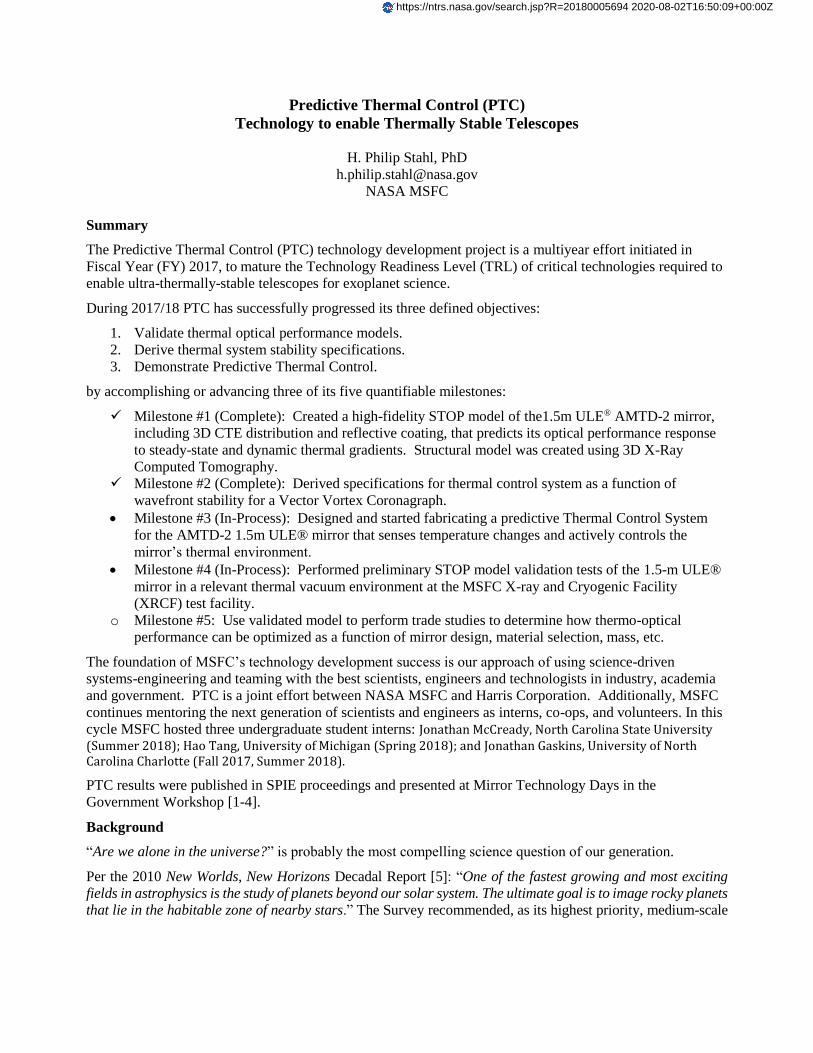
Predictive Thermal Control (PTC)
Technology to enable Thermally Stable Telescopes
H. Philip Stahl, PhD
NASA MSFC
Summary
The Predictive Thermal Control (PTC) technology development project is a multiyear effort initiated in
Fiscal Year (FY) 2017, to mature the Technology Readiness Level (TRL) of critical technologies required to
enable ultra-thermally-stable telescopes for exoplanet science.
During 2017/18 PTC has successfully progressed its three defined objectives:
1. Validate thermal optical performance models.
2. Derive thermal system stability specifications.
3. Demonstrate Predictive Thermal Control.
by accomplishing or advancing three of its five quantifiable milestones:
Milestone #1 (Complete): Created a high-fidelity STOP model of the1.5m ULE® AMTD-2 mirror,
including 3D CTE distribution and reflective coating, that predicts its optical performance response
to steady-state and dynamic thermal gradients. Structural model was created using 3D X-Ray
Computed Tomography.
Milestone #2 (Complete): Derived specifications for thermal control system as a function of
wavefront stability for a Vector Vortex Coronagraph.
Milestone #3 (In-Process): Designed and started fabricating a predictive Thermal Control System
for the AMTD-2 1.5m ULE® mirror that senses temperature changes and actively controls the
mirror’s thermal environment.
Milestone #4 (In-Process): Performed preliminary STOP model validation tests of the 1.5-m ULE®
mirror in a relevant thermal vacuum environment at the MSFC X-ray and Cryogenic Facility
(XRCF) test facility.
o Milestone #5: Use validated model to perform trade studies to determine how thermo-optical
performance can be optimized as a function of mirror design, material selection, mass, etc.
The foundation of MSFC’s technology development success is our approach of using science-driven
systems-engineering and teaming with the best scientists, engineers and technologists in industry, academia
and government. PTC is a joint effort between NASA MSFC and Harris Corporation. Additionally, MSFC
continues mentoring the next generation of scientists and engineers as interns, co-ops, and volunteers. In this
cycle MSFC hosted three undergraduate student interns: Jonathan McCready, North Carolina State University (Summer 2018); Hao Tang, University of Michigan (Spring 2018); and Jonathan Gaskins, University of North Carolina Charlotte (Fall 2017, Summer 2018).
PTC results were published in SPIE proceedings and presented at Mirror Technology Days in the
Government Workshop [1-4].
Background
“Are we alone in the universe?” is probably the most compelling science question of our generation.
Per the 2010 New Worlds, New Horizons Decadal Report [5]: “One of the fastest growing and most exciting
fields in astrophysics is the study of planets beyond our solar system. The ultimate goal is to image rocky planets
that lie in the habitable zone of nearby stars.” The Survey recommended, as its highest priority, medium-scale
https://ntrs.nasa.gov/search.jsp?R=20180005694 2020-08-02T16:50:09+00:00Z
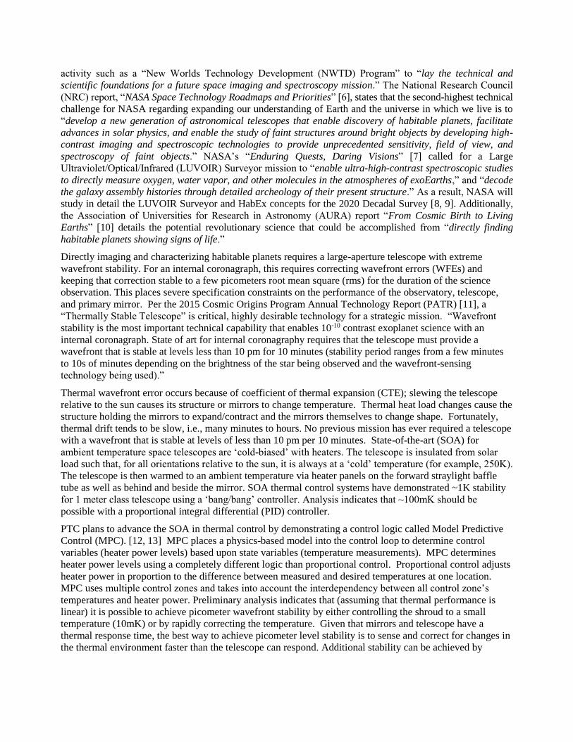
activity such as a “New Worlds Technology Development (NWTD) Program” to “lay the technical and
scientific foundations for a future space imaging and spectroscopy mission.” The National Research Council
(NRC) report, “NASA Space Technology Roadmaps and Priorities” [6], states that the second-highest technical
challenge for NASA regarding expanding our understanding of Earth and the universe in which we live is to
“develop a new generation of astronomical telescopes that enable discovery of habitable planets, facilitate
advances in solar physics, and enable the study of faint structures around bright objects by developing high-
contrast imaging and spectroscopic technologies to provide unprecedented sensitivity, field of view, and
spectroscopy of faint objects.” NASA’s “Enduring Quests, Daring Visions” [7] called for a Large
Ultraviolet/Optical/Infrared (LUVOIR) Surveyor mission to “enable ultra-high-contrast spectroscopic studies
to directly measure oxygen, water vapor, and other molecules in the atmospheres of exoEarths,” and “decode
the galaxy assembly histories through detailed archeology of their present structure.” As a result, NASA will
study in detail the LUVOIR Surveyor and HabEx concepts for the 2020 Decadal Survey [8, 9]. Additionally,
the Association of Universities for Research in Astronomy (AURA) report “From Cosmic Birth to Living
Earths” [10] details the potential revolutionary science that could be accomplished from “directly finding
habitable planets showing signs of life.”
Directly imaging and characterizing habitable planets requires a large-aperture telescope with extreme
wavefront stability. For an internal coronagraph, this requires correcting wavefront errors (WFEs) and
keeping that correction stable to a few picometers root mean square (rms) for the duration of the science
observation. This places severe specification constraints on the performance of the observatory, telescope,
and primary mirror. Per the 2015 Cosmic Origins Program Annual Technology Report (PATR) [11], a
“Thermally Stable Telescope” is critical, highly desirable technology for a strategic mission. “Wavefront
stability is the most important technical capability that enables 10-10 contrast exoplanet science with an
internal coronagraph. State of art for internal coronagraphy requires that the telescope must provide a
wavefront that is stable at levels less than 10 pm for 10 minutes (stability period ranges from a few minutes
to 10s of minutes depending on the brightness of the star being observed and the wavefront-sensing
technology being used).”
Thermal wavefront error occurs because of coefficient of thermal expansion (CTE); slewing the telescope
relative to the sun causes its structure or mirrors to change temperature. Thermal heat load changes cause the
structure holding the mirrors to expand/contract and the mirrors themselves to change shape. Fortunately,
thermal drift tends to be slow, i.e., many minutes to hours. No previous mission has ever required a telescope
with a wavefront that is stable at levels of less than 10 pm per 10 minutes. State-of-the-art (SOA) for
ambient temperature space telescopes are ‘cold-biased’ with heaters. The telescope is insulated from solar
load such that, for all orientations relative to the sun, it is always at a ‘cold’ temperature (for example, 250K).
The telescope is then warmed to an ambient temperature via heater panels on the forward straylight baffle
tube as well as behind and beside the mirror. SOA thermal control systems have demonstrated ~1K stability
for 1 meter class telescope using a ‘bang/bang’ controller. Analysis indicates that ~100mK should be
possible with a proportional integral differential (PID) controller.
PTC plans to advance the SOA in thermal control by demonstrating a control logic called Model Predictive
Control (MPC). [12, 13] MPC places a physics-based model into the control loop to determine control
variables (heater power levels) based upon state variables (temperature measurements). MPC determines
heater power levels using a completely different logic than proportional control. Proportional control adjusts
heater power in proportion to the difference between measured and desired temperatures at one location.
MPC uses multiple control zones and takes into account the interdependency between all control zone’s
temperatures and heater power. Preliminary analysis indicates that (assuming that thermal performance is
linear) it is possible to achieve picometer wavefront stability by either controlling the shroud to a small
temperature (10mK) or by rapidly correcting the temperature. Given that mirrors and telescope have a
thermal response time, the best way to achieve picometer level stability is to sense and correct for changes in
the thermal environment faster than the telescope can respond. Additional stability can be achieved by
increasing the system’s thermal mass. Based on this analysis, we assess the current TRL of such a system to
be TRL-3. PTC will advance this TRL by test using the 1.5-m Ultra Low Expansion (ULE®) mirror
fabricated by Advanced Mirror Technology Development (AMTD-2).
Objectives and Milestone:
PTC has defined three objectives to mature by at least 0.5 TRL step the technology needed for an exoplanet
science thermally stable telescope by developing “thermal design techniques validated by traceable
characterization testing of components”:
1. Validating models that predict thermal optical performance of real mirrors and structure based
on their structural designs and constituent material properties, i.e., CTE distribution, thermal
conductivity, thermal mass, etc.
2. Deriving thermal system stability specifications from wavefront stability requirement.
3. Demonstrating utility of a Predictive Control thermal system for achieving thermal stability.
To achieve our objectives, we have defined a detailed technical plan with five quantifiable milestones:
Milestone #1: Develop a high-fidelity traceable model of the 1.5m ULE® AMTD-2 mirror, including 3D
CTE distribution and reflective coating, that predicts its optical performance response to steady-state and
dynamic thermal gradients.
Milestone #2: Derive specifications for thermal control system as a function of wavefront stability.
Milestone #3: Design and build a predictive Thermal Control System for a 1.5m ULE® mirror that
senses temperature changes and actively controls the mirror’s thermal environment.
Milestone #4: Validate model by testing the 1.5-m ULE® mirror in a relevant thermal vacuum
environment at the MSFC X-ray and Cryogenic Facility (XRCF) test facility.
Milestone #5: Use validated model to perform trade studies to determine how thermo-optical
performance can be optimized as a function of mirror design, material selection, mass, etc.
Progress and Accomplishment:
Objective #1: Validated High-Fidelity Structural-Thermal-Optical-Performance (STOP) Model
Need: Designing a telescope to have 10 pm per 10 minute WFE stability using model predictive control
requires a validated high-fidelity STOP model.
Milestone #1: Develop a high-fidelity STOP model of the1.5m ULE® AMTD-2 mirror, including 3D CTE
distribution and reflective coating, that predicts its optical performance response to steady-state and dynamic
thermal gradients.
Milestone #4: Validate high-fidelity STOP model by testing the 1.5-m ULE® mirror in a relevant thermal
vacuum environment at the MSFC X-ray and Cryogenic Facility (XRCF) test facility.
Accomplishment: During FY 2018, PTC completed Milestone #1 and advanced Milestone #4. A high-
fidelity model of 1.5m ULE® AMTD-2 mirror was developed and used to correlate a 231K static thermal
soak deformation of approximately 20 nm rms to an uncertainty of 13.4 nm rms. Additionally, it was used to
correlate a deformation of approximately 80 nm rms for a 115K lateral thermal gradient.
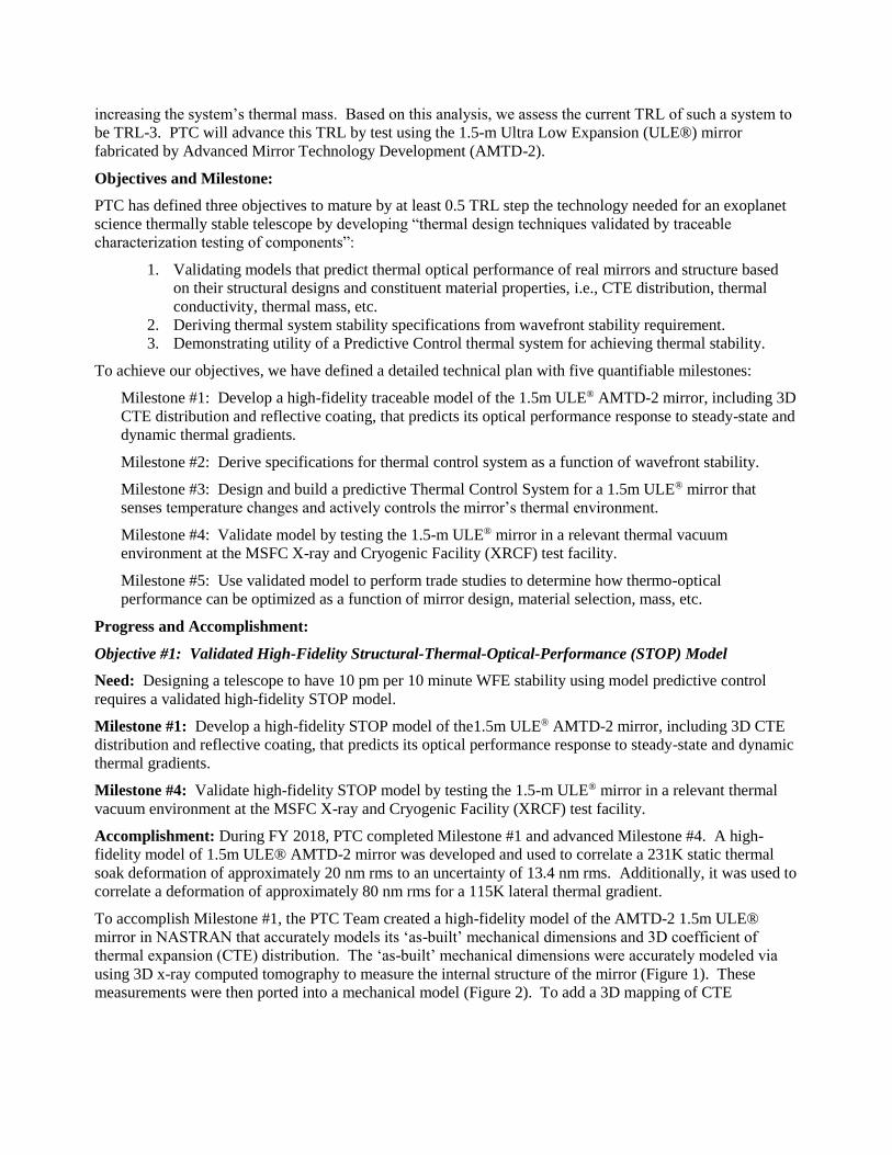
To accomplish Milestone #1, the PTC Team created a high-fidelity model of the AMTD-2 1.5m ULE®
mirror in NASTRAN that accurately models its ‘as-built’ mechanical dimensions and 3D coefficient of
thermal expansion (CTE) distribution. The ‘as-built’ mechanical dimensions were accurately modeled via
using 3D x-ray computed tomography to measure the internal structure of the mirror (Figure 1). These
measurements were then ported into a mechanical model (Figure 2). To add a 3D mapping of CTE
distribution, Harris Corporation provided MSFC with Corning CTE data maps for each of the 18 core
elements and the location where each element is located in the core (Figure 3).
The process by which the AMTD-2 mirror was fabricated resulted in bowing of the core walls. The effect
was discovered because the ATMD-2 mirror was deliberately fabricated to a very fast F/# which place the
mirror in to an unusually high stress state during fabrication. Such a stress state would not be imposed on an
actual flight mirror. The 3D X-ray CT scan produced a 3D mapping of the core wall bowing. A custom
algorithm was written to convert the X-ray CT 3D mapping into a finite element model.
To advance Milestone #4, the 1.5m ULE® AMTD-2 mirror’s response to static thermal loads and lateral
thermal gradients was tested in the XRCF. This test was conducted jointly with the AMTD-2 static thermal
soak test. This test was a bare mirror only test, i.e. mirror only with no thermal control system.
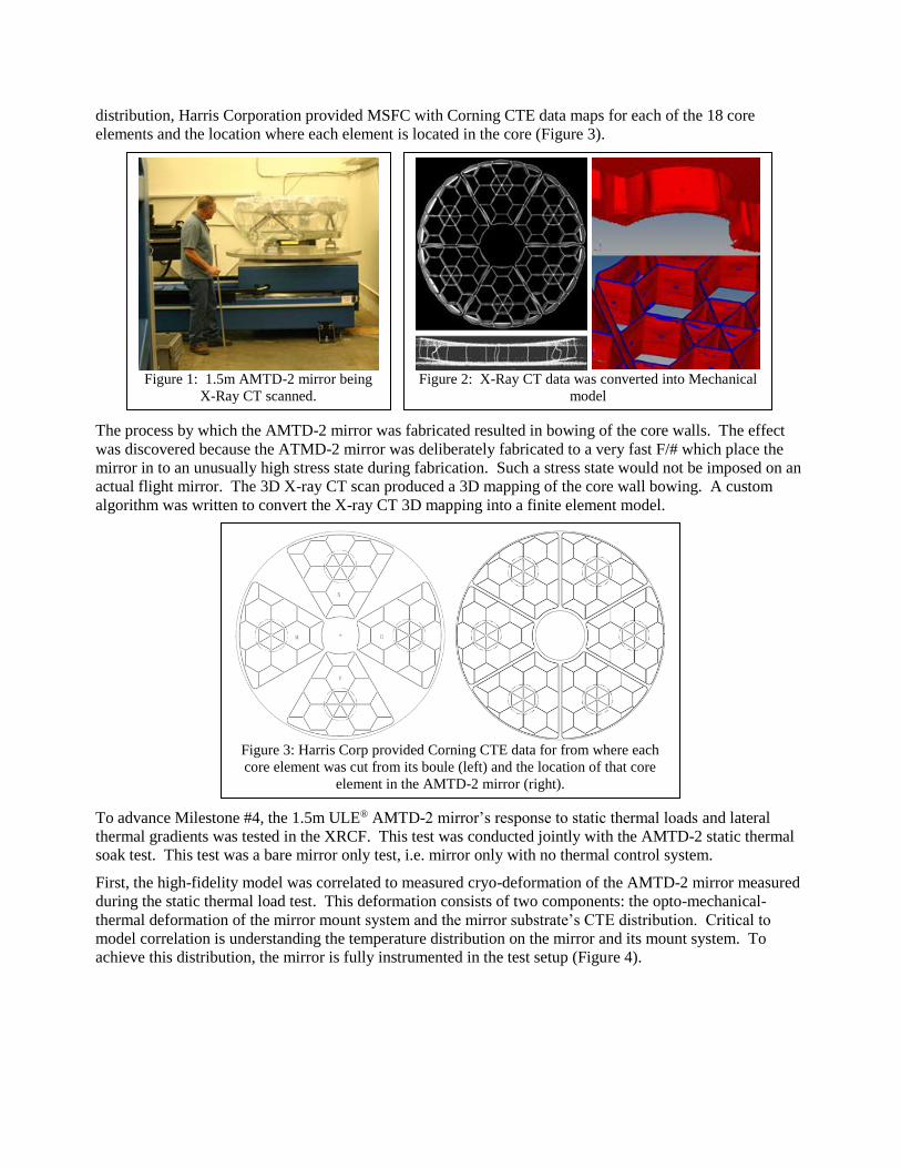
First, the high-fidelity model was correlated to measured cryo-deformation of the AMTD-2 mirror measured
during the static thermal load test. This deformation consists of two components: the opto-mechanical-
thermal deformation of the mirror mount system and the mirror substrate’s CTE distribution. Critical to
model correlation is understanding the temperature distribution on the mirror and its mount system. To
achieve this distribution, the mirror is fully instrumented in the test setup (Figure 4).
Figure 1: 1.5m AMTD-2 mirror being
X-Ray CT scanned.
Figure 2: X-Ray CT data was converted into Mechanical
model
Figure 3: Harris Corp provided Corning CTE data for from where each
core element was cut from its boule (left) and the location of that core
element in the AMTD-2 mirror (right).
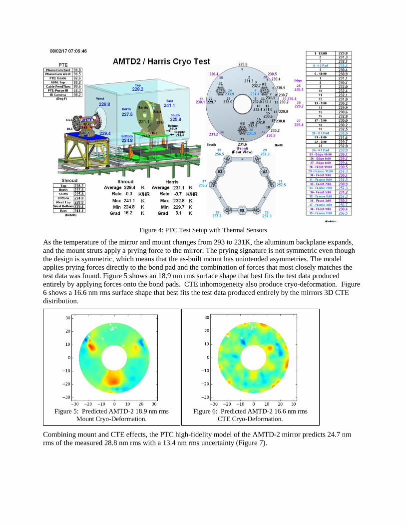
Figure 4: PTC Test Setup with Thermal Sensors
As the temperature of the mirror and mount changes from 293 to 231K, the aluminum backplane expands,
and the mount struts apply a prying force to the mirror. The prying signature is not symmetric even though
the design is symmetric, which means that the as-built mount has unintended asymmetries. The model
applies prying forces directly to the bond pad and the combination of forces that most closely matches the
test data was found. Figure 5 shows an 18.9 nm rms surface shape that best fits the test data produced
entirely by applying forces onto the bond pads. CTE inhomogeneity also produce cryo-deformation. Figure
6 shows a 16.6 nm rms surface shape that best fits the test data produced entirely by the mirrors 3D CTE
distribution.
Combining mount and CTE effects, the PTC high-fidelity model of the AMTD-2 mirror predicts 24.7 nm
rms of the measured 28.8 nm rms with a 13.4 nm rms uncertainty (Figure 7).
Figure 5: Predicted AMTD-2 18.9 nm rms
Mount Cryo-Deformation.
Figure 6: Predicted AMTD-2 16.6 nm rms
CTE Cryo-Deformation.
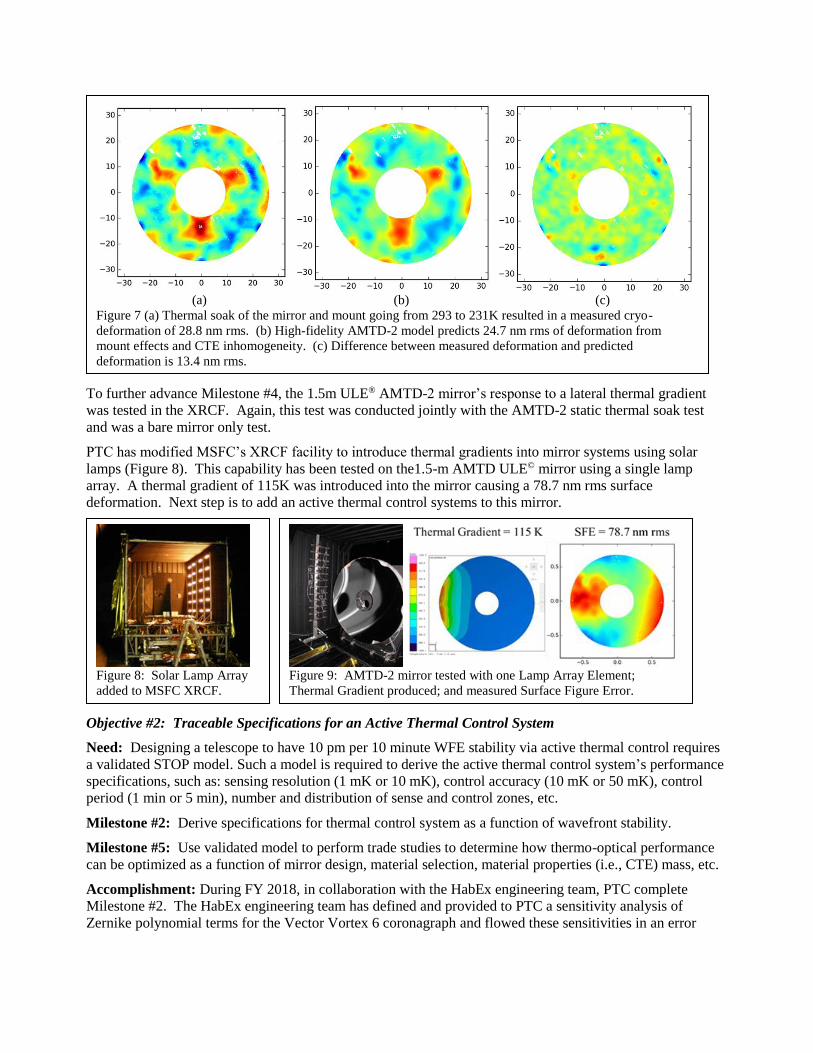
To further advance Milestone #4, the 1.5m ULE® AMTD-2 mirror’s response to a lateral thermal gradient
was tested in the XRCF. Again, this test was conducted jointly with the AMTD-2 static thermal soak test
and was a bare mirror only test.
PTC has modified MSFC’s XRCF facility to introduce thermal gradients into mirror systems using solar
lamps (Figure 8). This capability has been tested on the1.5-m AMTD ULE© mirror using a single lamp
array. A thermal gradient of 115K was introduced into the mirror causing a 78.7 nm rms surface
deformation. Next step is to add an active thermal control systems to this mirror.
Objective #2: Traceable Specifications for an Active Thermal Control System
Need: Designing a telescope to have 10 pm per 10 minute WFE stability via active thermal control requires
a validated STOP model. Such a model is required to derive the active thermal control system’s performance
specifications, such as: sensing resolution (1 mK or 10 mK), control accuracy (10 mK or 50 mK), control
period (1 min or 5 min), number and distribution of sense and control zones, etc.
Milestone #2: Derive specifications for thermal control system as a function of wavefront stability.
Milestone #5: Use validated model to perform trade studies to determine how thermo-optical performance
can be optimized as a function of mirror design, material selection, material properties (i.e., CTE) mass, etc.
Accomplishment: During FY 2018, in collaboration with the HabEx engineering team, PTC complete
Milestone #2. The HabEx engineering team has defined and provided to PTC a sensitivity analysis of
Zernike polynomial terms for the Vector Vortex 6 coronagraph and flowed these sensitivities in an error
(a) (b) (c) Figure 7 (a) Thermal soak of the mirror and mount going from 293 to 231K resulted in a measured cryo-
deformation of 28.8 nm rms. (b) High-fidelity AMTD-2 model predicts 24.7 nm rms of deformation from
mount effects and CTE inhomogeneity. (c) Difference between measured deformation and predicted
deformation is 13.4 nm rms.
Figure 8: Solar Lamp Array
added to MSFC XRCF.
Figure 9: AMTD-2 mirror tested with one Lamp Array Element;
Thermal Gradient produced; and measured Surface Figure Error.
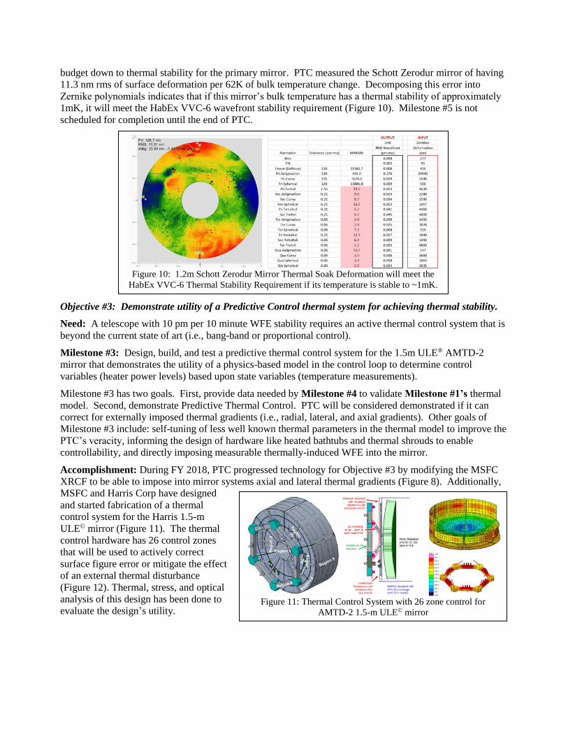
budget down to thermal stability for the primary mirror. PTC measured the Schott Zerodur mirror of having
11.3 nm rms of surface deformation per 62K of bulk temperature change. Decomposing this error into
Zernike polynomials indicates that if this mirror’s bulk temperature has a thermal stability of approximately
1mK, it will meet the HabEx VVC-6 wavefront stability requirement (Figure 10). Milestone #5 is not
scheduled for completion until the end of PTC.
Objective #3: Demonstrate utility of a Predictive Control thermal system for achieving thermal stability.
Need: A telescope with 10 pm per 10 minute WFE stability requires an active thermal control system that is
beyond the current state of art (i.e., bang-band or proportional control).
Milestone #3: Design, build, and test a predictive thermal control system for the 1.5m ULE® AMTD-2
mirror that demonstrates the utility of a physics-based model in the control loop to determine control
variables (heater power levels) based upon state variables (temperature measurements).
Milestone #3 has two goals. First, provide data needed by Milestone #4 to validate Milestone #1’s thermal
model. Second, demonstrate Predictive Thermal Control. PTC will be considered demonstrated if it can
correct for externally imposed thermal gradients (i.e., radial, lateral, and axial gradients). Other goals of
Milestone #3 include: self-tuning of less well known thermal parameters in the thermal model to improve the
PTC’s veracity, informing the design of hardware like heated bathtubs and thermal shrouds to enable
controllability, and directly imposing measurable thermally-induced WFE into the mirror.
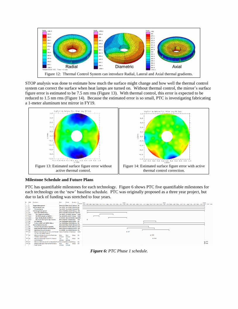
Accomplishment: During FY 2018, PTC progressed technology for Objective #3 by modifying the MSFC
XRCF to be able to impose into mirror systems axial and lateral thermal gradients (Figure 8). Additionally,
MSFC and Harris Corp have designed
and started fabrication of a thermal
control system for the Harris 1.5-m
ULE© mirror (Figure 11). The thermal
control hardware has 26 control zones
that will be used to actively correct
surface figure error or mitigate the effect
of an external thermal disturbance
(Figure 12). Thermal, stress, and optical
analysis of this design has been done to
evaluate the design’s utility.
Figure 10: 1.2m Schott Zerodur Mirror Thermal Soak Deformation will meet the
HabEx VVC-6 Thermal Stability Requirement if its temperature is stable to ~1mK.
Figure 11: Thermal Control System with 26 zone control for
AMTD-2 1.5-m ULE© mirror
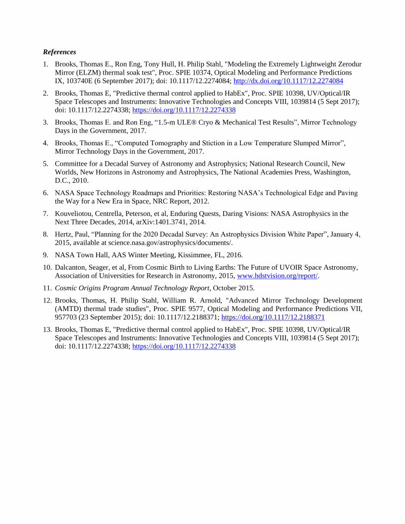
STOP analysis was done to estimate how much the surface might change and how well the thermal control
system can correct the surface when heat lamps are turned on. Without thermal control, the mirror’s surface
figure error is estimated to be 7.5 nm rms (Figure 13). With thermal control, this error is expected to be
reduced to 1.5 nm rms (Figure 14). Because the estimated error is so small, PTC is investigating fabricating
a 1-meter aluminum test mirror in FY19.
Milestone Schedule and Future Plans
PTC has quantifiable milestones for each technology. Figure 6 shows PTC five quantifiable milestones for
each technology on the ‘new’ baseline schedule. PTC was originally proposed as a three year project, but
due to lack of funding was stretched to four years.
Figure 6: PTC Phase 1 schedule.
Figure 12: Thermal Control System can introduce Radial, Lateral and Axial thermal gradients.
Figure 13: Estimated surface figure error without
active thermal control.
Figure 14: Estimated surface figure error with active
thermal control correction.
References
1. Brooks, Thomas E., Ron Eng, Tony Hull, H. Philip Stahl, "Modeling the Extremely Lightweight Zerodur
Mirror (ELZM) thermal soak test", Proc. SPIE 10374, Optical Modeling and Performance Predictions
IX, 103740E (6 September 2017); doi: 10.1117/12.2274084; http://dx.doi.org/10.1117/12.2274084
2. Brooks, Thomas E, "Predictive thermal control applied to HabEx", Proc. SPIE 10398, UV/Optical/IR
Space Telescopes and Instruments: Innovative Technologies and Concepts VIII, 1039814 (5 Sept 2017);
doi: 10.1117/12.2274338; https://doi.org/10.1117/12.2274338
3. Brooks, Thomas E. and Ron Eng, “1.5-m ULE® Cryo & Mechanical Test Results”, Mirror Technology
Days in the Government, 2017.
4. Brooks, Thomas E., “Computed Tomography and Stiction in a Low Temperature Slumped Mirror”,
Mirror Technology Days in the Government, 2017.
5. Committee for a Decadal Survey of Astronomy and Astrophysics; National Research Council, New
Worlds, New Horizons in Astronomy and Astrophysics, The National Academies Press, Washington,
D.C., 2010.
6. NASA Space Technology Roadmaps and Priorities: Restoring NASA’s Technological Edge and Paving
the Way for a New Era in Space, NRC Report, 2012.
7. Kouveliotou, Centrella, Peterson, et al, Enduring Quests, Daring Visions: NASA Astrophysics in the
Next Three Decades, 2014, arXiv:1401.3741, 2014.
8. Hertz, Paul, “Planning for the 2020 Decadal Survey: An Astrophysics Division White Paper”, January 4,
2015, available at science.nasa.gov/astrophysics/documents/.
9. NASA Town Hall, AAS Winter Meeting, Kissimmee, FL, 2016.
10. Dalcanton, Seager, et al, From Cosmic Birth to Living Earths: The Future of UVOIR Space Astronomy,
Association of Universities for Research in Astronomy, 2015, www.hdstvision.org/report/.
11. Cosmic Origins Program Annual Technology Report, October 2015.
12. Brooks, Thomas, H. Philip Stahl, William R. Arnold, "Advanced Mirror Technology Development
(AMTD) thermal trade studies", Proc. SPIE 9577, Optical Modeling and Performance Predictions VII,
957703 (23 September 2015); doi: 10.1117/12.2188371; https://doi.org/10.1117/12.2188371
13. Brooks, Thomas E, "Predictive thermal control applied to HabEx", Proc. SPIE 10398, UV/Optical/IR
Space Telescopes and Instruments: Innovative Technologies and Concepts VIII, 1039814 (5 Sept 2017);
doi: 10.1117/12.2274338; https://doi.org/10.1117/12.2274338