Embed Size (px)
Citation preview
i

Preface
Copyright 2004 All Rights Reserved. The information in this document is subject to change without prior notice in order to improve reliability, design and function and does not represent a commitment on the part of the manufacturer. In no event will the manufacturer be liable for direct, indirect, special, incidental, or consequential damages arising out of the use or inability to use the product or documentation, even if advised of the possibility of such damages. This document contains proprietary information protected by copyright. All rights are reserved. No part of this manual may be reproduced by any mechanical, electronic, or other means in any form without prior written permission of the manufacturer.
Trademarks AutoCAD and Autoshade are trademarks of Autodesk, Inc. IBM, OS/2, and VGA are trademarks of International Business Machines Corp. Lotus, 1-2-3, and Symphony are trademarks of Lotus Development Corp. Windows, Word, MS-DOS, and Microsoft are trademarks of Microsoft Corp. VESA is a trademark of Video Electronics Standards Association. Other product names mentioned herein are used for identification purposes only and may be trademarks and/or registered trademarks of their respective companies.
Limitation of Liability
While reasonable efforts have been made to ensure the accuracy of this manual, the manufacturer and distributor assume no liability resulting from errors or omissions in this manual, or from the use of the information contained herein.
i
Notices
Federal Communications Commission Radio Frequency Interference Statement
This equipment has been tested and found to comply with the limits for a Class B digital device, pursuant to Part 15 of the FCC Rules. These limits are designed to provide reasonable protection against harmful interference in a residential installation. This equipment generates, uses, and can radiate radio frequency energy and if not installed and used in accordance with the instruction manual may cause harmful interference to radio communications. However, there is no guarantee that interference will not occur in a particular installation. If this equipment does cause harmful interference to radio or television reception, which can be determined by turning the equipment off and on, the user is encouraged to try to correct the interference by one or more of the following measures: • Reorient or relocate the receiving antenna • Increase the separation between the equipment and receiver • Connect the equipment into an outlet on a circuit different from
that to which the receiver is connected • Consult the dealer or an experienced radio TV technician for help
Notice: Changes or modifications not expressly approved by the party responsible for compliance could void the user’s authority to operate the equipment. Shielded interface cables and a non-shielded AC power cord must be used in order to comply with emission limits. This equipment is to be used with power supply: I/P: 100-240 Vac, 50-60Hz, 2.5A O/P: 19Vdc, 7.9A There is no internal power supply.
ii
Table of Content
Chapter 1: Before you Start ........................................................ 1 Conventions of This Manual ............................................................. 1 Safety Precautions............................................................................. 2 Wichtige Sicherheitshinweise ........................................................... 4 Things you must remember before working on your computer.......... 7
Chapter 2: Introduction ............................................................... 9 Welcome to the Notebook PC ........................................................... 9 Unpacking the Notebook................................................................... 9 Getting to Know Your Computer ...................................................... 10
Chapter 3: Getting Started .........................................................19 Connecting to a Power Source .......................................................... 19 Turning On Your Notebook Computer .............................................. 20 Inserting and Removing the Battery Pack ......................................... 21 Charging the Battery Pack................................................................. 22
Chapter 4: Using the Notebook Computer ................................23 Adjusting the LCD Screen Display ................................................... 23 The TouchPad ................................................................................... 26 Data Storage and Retrieval................................................................ 26 Power Saving Modes......................................................................... 28 Resetting the System......................................................................... 31
Chapter 5: Desktop Operation ...................................................33 Audio ................................................................................................ 33 Connecting Peripheral Devices ......................................................... 34
Chapter 6: Configuring and Maintaining your System.............37 Introduction ...................................................................................... 37
Chapter 7: Raid Setting (Option) ...............................................45 Raid Setting (If Your System Supports RAID).................................. 45 Installing the System OS................................................................... 46
Chapter 8: Microsoft Center Edition (MCE) (Option)...............49 Windows XP Media Center Edition (MCE)....................................... 49
Chapter 9: The Software Utilities Disks ....................................51 AutoRun Installation ......................................................................... 51 Manual Installation ........................................................................... 53 VGA Utilities.................................................................................... 56
Chapter 10: Viewing Live Video .................................................63
iii
Using the Remote Control ................................................................. 63 WinDVR Mode ................................................................................. 64 Defining the Video Source ................................................................ 65
Chapter 11: Troubleshooting .....................................................73 Locating a Problem ........................................................................... 73 Checking Cables and Connections .................................................... 74 The Power-On Self Test .................................................................... 75 General Hardware Problems.............................................................. 75 Contacting Your Dealer .................................................................... 77
Chapter 12: How do I Expand my Notebook ............................79 Upgrading your Memory................................................................... 79 Easy to Upgrade HDD Module.......................................................... 80 CPU Upgrade .................................................................................... 82
Appendix A: Specification..........................................................85 Detailed Notebook Specifications ..................................................... 85
iv

Canadian DOC Notice For Class B Computing Devices This Class B digital apparatus meets all requirements of the Canadian Interference - Causing Equipment Regulations. Cet appareil numerique de la classe B repecte toutes les exigences du Règlement sur le matèriel brouilleur du Canada.
Personal Inventory
This Notebook computer system is designed for years of productive and pleasurable computing. Use this section to keep notes about details of your purchase. Update this section when you add new options.
Date of Purchase:
Dealer’s Name:
Phone:
Address:
E-Mail Address:
WWW Site:
Serial Number:
CPU Type:
Hard Disk Capacity:
Memory Capacity:
Optional Equipment:
v

BEFORE YOU START
Conventions of This Manual
Use this manual will help you get the most from your notebook computer. • If you are an experienced user of computers and/or Microsoft’s
Windows operating systems, you might find it useful to read the Quick Start Guide that comes along with your accessories.
• If you are a less experienced user, you should through the manual carefully before using your system.
Whether or not you are an experienced user, you should consult on the Troubleshooting Chapter if you encounter any problems with your notebook.
The check mark symbol indicates that you should take note on every detailed information when you encounter some function that might be useful when you are using your notebook.
The pencil symbol identifies information which is important for you to read to avoid damage to the computer.
This warning cautions you against actions which might be destructive to your data or might disrupt proper system operation.
1
Safety Precautions
This section is designed to assist you in identifying potentially unsafe conditions while working with this product. Required safety features have been installed in the computer to protect you from injury. However, you should use good judgment to identify potential safety hazards: 1. 2. 3.
4.
5. 6.
7.
8.
9. 10.
11.
12.
13.
a. b. c. d.
Please read these safety instructions carefully. Please keep this User's Manual for later reference. Please disconnect this equipment from AC outlet before cleaning. Don't use liquid or sprayed detergent for cleaning. Use moisture sheet or cloth for cleaning. For pluggable equipment, that the socket-outlet shall be installed near the equipment and shall be easily accessible. Please keep this equipment from humidity. Lay this equipment on a reliable surface when installed. A drop or fall could cause injury. Make sure to use the right voltage for the power source when connecting the equipment to the power outlet. Place the power cord in such a way that people can not step on it. Do not place anything on top of the power cord. All cautions and warnings on the equipment should be noted. If the equipment is not use for a long time, disconnect the equipment from the main power outlet to avoid being damaged by transient overvoltage. Never pour any liquid into the opening, this could cause fire or electrical shock. Never open the equipment. For safety reason, the equipment should only be opened by a qualified service personnel. If on the following situations arises, get the equipment checked by a service personnel:
The Power cord or plug is damaged. Liquid has penetrated into the equipment. The equipment has been exposed to moisture. The equipment has not worked well or you cannot get it work according to the user's manual.
2
e. f.
14.
15. 16.
17.
A.
B.
C.
The equipment has dropped and damaged. If the equipment has obvious sign of breakage.
Do not leave this equipment in an environment unconditioned, storage temperature above 60°C (140°f), it may damage the equipment. The unit can be operated at an ambient temperature of max. 35°C. The sound pressure level at the operators position according to IEC 704-1: 1982 is equal or less than 70 dB(A). Power Cord Requirements The power cord set used with the AC adaptor must meet the requirements of the country where you use the AC adaptor, whether it is 100-120 or 200-240 Vac. The following information explains the requirements for power cord set selection.
The cord set must be approved for the country in which it is used. The appliance coupler must have a configuration for mating with a CEE22/EN6032/IEC 320 appliance inlet.
For U.S. and Canada: The cord set must be UL Listed and CSA Certified. The minimum specifications for the flexible cord are No. 18 AWG.
For Japan: All components of the cord set must bear a “PSE” or “ T ” mark and registration number in accordance with the Japanese Dentori Law. The minimum specifications for the flexible cord are .75m ㎡ conductors.
For Other Countries: The cord set fittings must bear the certification mark of the agency responsible for evaluation in a specific country. The flexible cord must be of a HAR (harmonized) type H05VV-F. The cord set must have a current capacity of a least 2.5 Amperes and voltage rating of 125 or 250 Vac.
3

18.
19.
20.
21.
22.
When using your telephone equipment, basic safety precautions should always be followed to reduce the risk of fire, electric shock and injury to persons. These precautions includes the following:
• Do not use this product near water, for example, near a bathtub, washbowl, kitchen sink or laundry tub, in a wet basement or near a swimming pool.
• Avoid using a telephone (other than a cordless type) during an electrical storm. There may be a remote risk of electric shock from lightning.
• Do not use the telephone to report a gas leak in the vicinity of the leak.
• Use only the power cord indicated in this manual.
Do not use the AC adapter near open water or other liquids. Never spill liquid into the AC adapter. Laser Warning: Laser Class I Product Caution - Invisible laser radiation when open avoid exposure to beam. Danger of explosion if battery is incorrectly replaced. Replace only with the same or equivalent type recommended by the manufacturer. Dispose of used batteries according to the manufacturer's instructions. Never remove the battery pack while the power is on as this may result in data loss when the system loses power. The input receptacle is used as the main disconnecting device.
Wichtige Sicherheitshinweise
1. 2. 3.
4.
5. 6.
7.
Bitte lesen Sie diese Hinweis sorgfältig durch. Heben Sie dirse Anleitung für den späteren Gebrauch auf. Vor jedem Reinigen ist das Gerät vom Stromnetz zu trennen. Versenden Sie Keine Flüssig- oder Aerosolreiniger. Am besten eignet sich ein angefeuchtetes Tuch zur Reinigung. Die Netzanschluβsteckdose soll nahe dem Gerät angebracht und leicht zugänglich sein. Das Gerät ist vor Feuchtigkeit zu schützen. Bei der Aufstellung des Gerätes ist auf sicheren Stand zu achten. Ein Kippen oder Fallen könnte Beschädigungen hervorrufen. Beachten Sie beim Anschluß an das Stromnet die Anschlußwerte.
4
8.
9.
10.
11.
12.
13.
a. b. c. d.
e. f.
14.
15.
16.
17.
Verlegen Sie die Netzanschlußleitung so, daß niemand darüber fallen kann. Es sollte auch nichts auf der Leitun abgestellt werden. Alle Hinweise und Warnungen, die sich am Gerät befinden, sind zu beachten. Wird das Gerät üeinen längeren Zeitraum nicht benutzt, sollten Sie es vom Stromnetz trennen. Somit wird im Falle einer Überspannung eine Beschädigung vermieden. Durch die Lüftungsöffnungen dürfen niemals Gegenstände oder Flüssigkeien in das Gerät gelangen. Dies könne einen Brand bzw. Elektrischen Schlag auslösen. Öffnen Sie niemals das Gerät. Das Gerät darf aus Gründen der elektrischen Sicherheit nur von authorisiertem Servicepersonal geöffnet werden. Wenn folgende Situationen auftreten ist das Gerät vom Stromnetz zu trennen und von einer qualifizierten Servicestelle zu Überprüfung.:
Netzlabel oder Netzstecker sind beschädigt. Flüssigkeit ist in das Gerät eingedrungen. Das Gerät war Feuchtigkeit ausgesetzt. Wenn das Gerät nicht der Bedienungsanleitung entsprechend funktioniert oder Sie mit Hilfe dieser Anleitung keine Verbesserung erzielen. Das Gerät ist gefallen und/oder das Gehäuse ist beschädigt. Wenn das Gerät deutliche Anzeichen eines Defektes aufweist.
VORSICHT: Explosiongsgetahr bei unsachgemäßen Austausch der Batterie. Ersatz nur durch denselben oder einem vom Hersteller empfohlenem ähnlichen Typ. Entsorgung gebrauchter Batterien nach Angaben des Herstellers. Dieses Schaltnetzteil kann bis zu einer Außentemperatur von maximal 35ºC. Die Ausgangswerte dürfen nicht die auf dem Label angegebenen Werte überschreiten. Anforderungen an das Stromkabel Das Kabel-Set, das an das Netzteil angeschlossen wird, muss den Anforderungen des Landes, in dem Sie das Netzteil einsetzen, genügen, je nachdem, ob die Netzspannung 100-120 oder 200-240V Wechselspannung beträgt.
5

Das Kabel-Set muss für das Land, in dem es eingesetzt wird, zugelassen sein.
A.
B.
C.
18.
Der Gerätestecker des Kabels muss in eine CEE22/ EN603/ IEC 320 Buchse passen.
Für die USA und Kanada: Das Kabel-Set muss UL-gelistet und CSA zertifiziert sein. Die Minimalanforderungen für das Kabel entsprechen No. 18 AWG.
Für Japan: Alle Teile des Kabel-Sets müssen entsprechend dem japanischen Dentori Law mit einem „PSE“ or „T”-Symbol markiert sein Die Minimalanforderungen für das Kabel sind .75m ㎡ Leiter.
Für andere Länder: Die Zubehörteile des Kabel-Sets müssen das Prüfsiegel derjenigen Stelle, die in dem jeweiligen Land für die Sicherheitsprüfung zuständig ist, tragen. Das Kabel muss vom HAR (harmonisierten) Typ H05VV-F sein. Das Kabel-Set muss eine Stromkapazität von mindestens 2,5 Ampere haben und Spannungen von 125 oder 250 V Wechselstrom gestatten.
Bei der Benutzung Ihres Telefongerätes sollten Sie immer die grundlegenden Sicherheitsmaßnahmen beachten, um das Risiko von Feuer, Stromschlägen und Verletzungen zu minimieren. Zu beachten sind u.a. folgende Punkte:
• Benutzen Sie das Gerät nicht in der Nähe von Wasser, wie zum Beispiel Badewanne, Waschbecken, Spülbecken, Waschbottich, in feuchten Kellerräumen oder in der Nähe von Schwimmbecken.
• Benutzen Sie kein Telefon (ausgenommen schnurlose Modelle) während eines Gewitters. Es besteht das geringe Restrisiko eines Blitzschlages.
6
• Benutzen Sie das Telefon nicht um ein Gasleck zu melden, falls es sich in der Nähe des Lecks befindet.
• Benutzen Sie nur solch ein Stromkabel, wie in dieser Anleitung beschrieben.
19.
20.
21.
22.
Benutzen Sie das Netzteil nicht in unmittelbarer Nähe zu Wasser oder anderen Flüssigkeiten. Gießen Sie nie Flüssigkeiten über das Netzteil. Achtung Laser: Laser Produkt der Klasse I. Achtung - Unsichtbarer Laserstrahl, vermeiden Sie Kontakt mit dem Strahl bei offenem Gehäuse. Es besteht Explosionsgefahr, wenn der Akku nicht ordnungsgemäß ersetzt wird. Ersetzen Sie den Akku nur durch einen Akku gleichen oder äquivalenten Typs, der vom Hersteller empfohlen wird. Entsorgen Sie Akkus entsprechend den Anweisungen des Herstellers. Entfernen Sie den Akku auf keinen Fall bei eingeschaltetem Notebook, da hierdurch Daten verloren gehen könnten. Der Netzeingabeanschluss dient als Hauptschalter des Geräts.
Things you must remember before working on your computer
Let your computer acclimate itself
Your notebook can easily stand temperature extremes but it doesn’t like rapid changes in temperature, like going from the cold outdoors to a warm office. Rapid changes in temperature can cause water droplets to condense inside your case, threatening to damage the electronic parts inside. After receiving your notebook when it’s hot or cold outside, try not to power up the computer immediately, let the computer adjust to the room temperature gradually at least for three to four hours.
If your system arrives in cold weather, do not apply power to the computer or monitor until they have been allowed to come to room temperature.
7
Heat, Cold, Humidity, and Glare
Find a suitable place for your computer that’s not too hot, too cold, too dark, or too bright. Glare can make it hard to read the screen. • Try to avoid the computer components from being destroyed if it is
over heated, so try to allow plenty of room for air to circulate around the case.
• Do not block the ventilation opening. • Do not place your computer in direct sunlight.
Suitable place to work
Your computer will run well wherever you’re comfortable but extremes of temperature and humidity can be challenging to your system’s parts. There are some things you can tolerate that the computer can’t – things like static electricity, dust, water, steam and oil. In case you decide to pull over for roadside computing, try to choose a clean, comfortable work area for your system. A lithium-ion battery pack will be available when you are traveling. If you are running your system for the first time on battery power, remove the battery from the package, install it into the system and recharge the battery to fully prepare for service.
8
INTRODUCTION
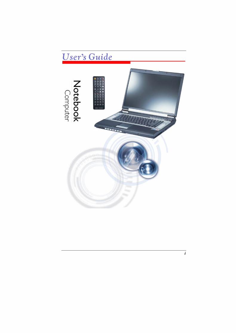
Welcome to the Notebook PC
Congratulations on your purchase of the Notebook PC. Your Notebook features the latest advances in portable computing technology. The Notebook’s modular design provides maximum expandability without compromising portability. The high-performance CPU and enhanced IDE hard drive provides you with extra processing power for handling complex graphics and running large programs. A premium notebook designed for successful executives who demand the very best and featuring ultimate power, ultimate wide screen display, ultimate AV capabilities and ultimate connectivity. A Media solution is a combination of Windows XP software augmented by InterVideo WinCinema – including WinDVR for watching television, WinDVD for viewing movies and WinRIP playing music plus – and hardware including five premium on board speakers delivering 5.1 channel output, an Audio DJ for playing music from the optical drive without powering up the PC and a full-featured remote control.
Unpacking the Notebook
The Notebook comes securely packaged in a sturdy cardboard shipping carton. Upon receiving your Notebook, open the carton and carefully remove the contents. If anything is missing or damaged, please contact your Notebook dealer immediately. The shipping carton should contain the following items: • The Notebook computer • An AC adapter • An AC power cord • Software Drivers CD
9

Do not throw the packaging materials away. You may need them later if you have to ship the computer for repairs.
Because the Notebook computer is available in different configurations, some of the features mentioned in this manual might not be included on your computer or may differ slightly.
Getting to Know Your Computer
Opening the LCD Panel
At the front of the Notebook you will find a retaining latch on the display panel that locks the display in closed position when the Notebook is not in use. 1.
2. 3.
Locate the display latch on the front of the unit. Slide the latch until the display panel releases. Raise the LCD screen and the machine will go to incline position. At any time you can tilt the display toward or away from you to a comfortable viewing position.
To avoid damage to the display panel: 1. 2.
Try not to slam the display upon closing it. Try not to place any object on top when it is closed or open.
10
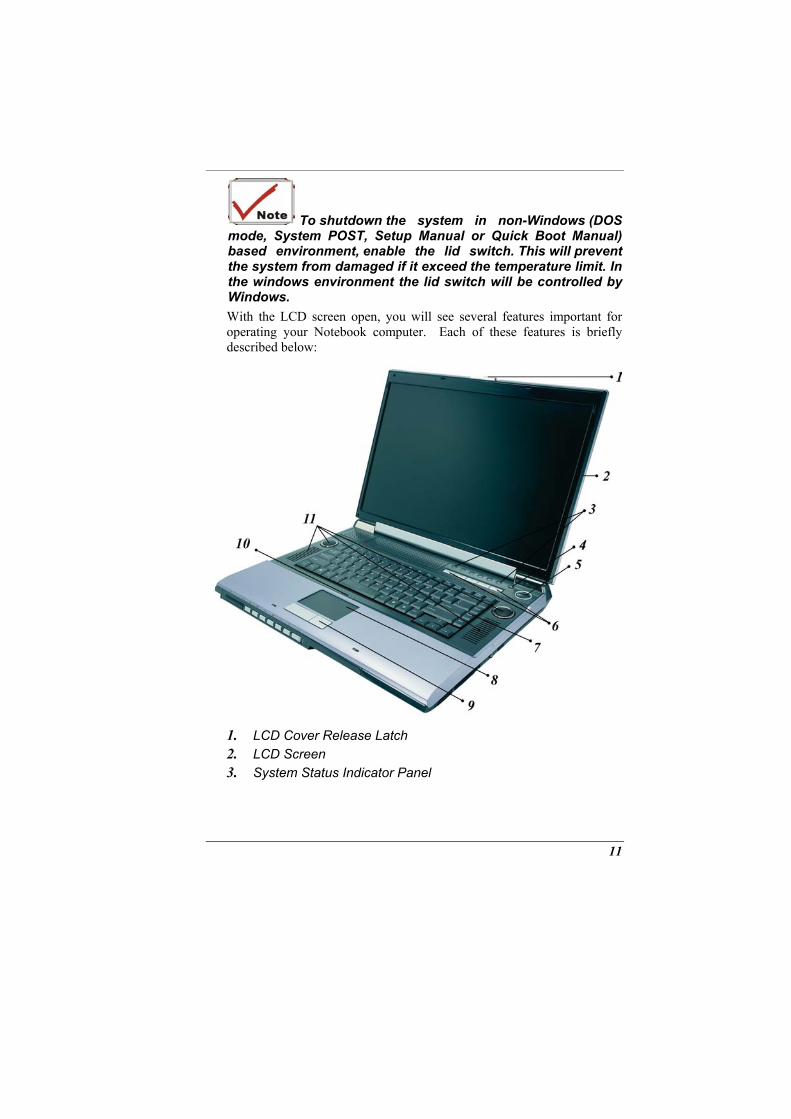
To shutdown the system in non-Windows (DOS mode, System POST, Setup Manual or Quick Boot Manual) based environment, enable the lid switch. This will prevent the system from damaged if it exceed the temperature limit. In the windows environment the lid switch will be controlled by Windows. With the LCD screen open, you will see several features important for operating your Notebook computer. Each of these features is briefly described below:
1. 2. 3.
LCD Cover Release Latch LCD Screen System Status Indicator Panel
11
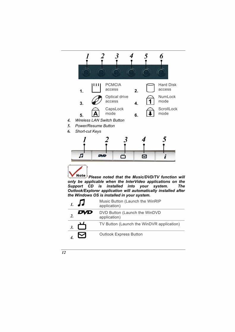
1. PCMCIA access 2.
Hard Disk access
3. Optical drive access 4.
NumLock mode
5. CapsLock mode 6.
ScrollLock mode
4. 5. 6.
Wireless LAN Switch Button Power/Resume Button Short-cut Keys
Please noted that the Music/DVD/TV function will only be applicable when the InterVideo applications on the Support CD is installed into your system. The Outlook/Explorer application will automatically installed after the Windows OS is installed in your system.
1. Music Button (Launch the WinRIP application)
2. DVD Button (Launch the WinDVD application)
3. TV Button (Launch the WinDVR application)
4. Outlook Express Button
12
5. Internet Explorer Button
7. 8. 9. 10. 11.
Keyboard TouchPad TouchPad Buttons The Built-in Microphone Stereo Speakers
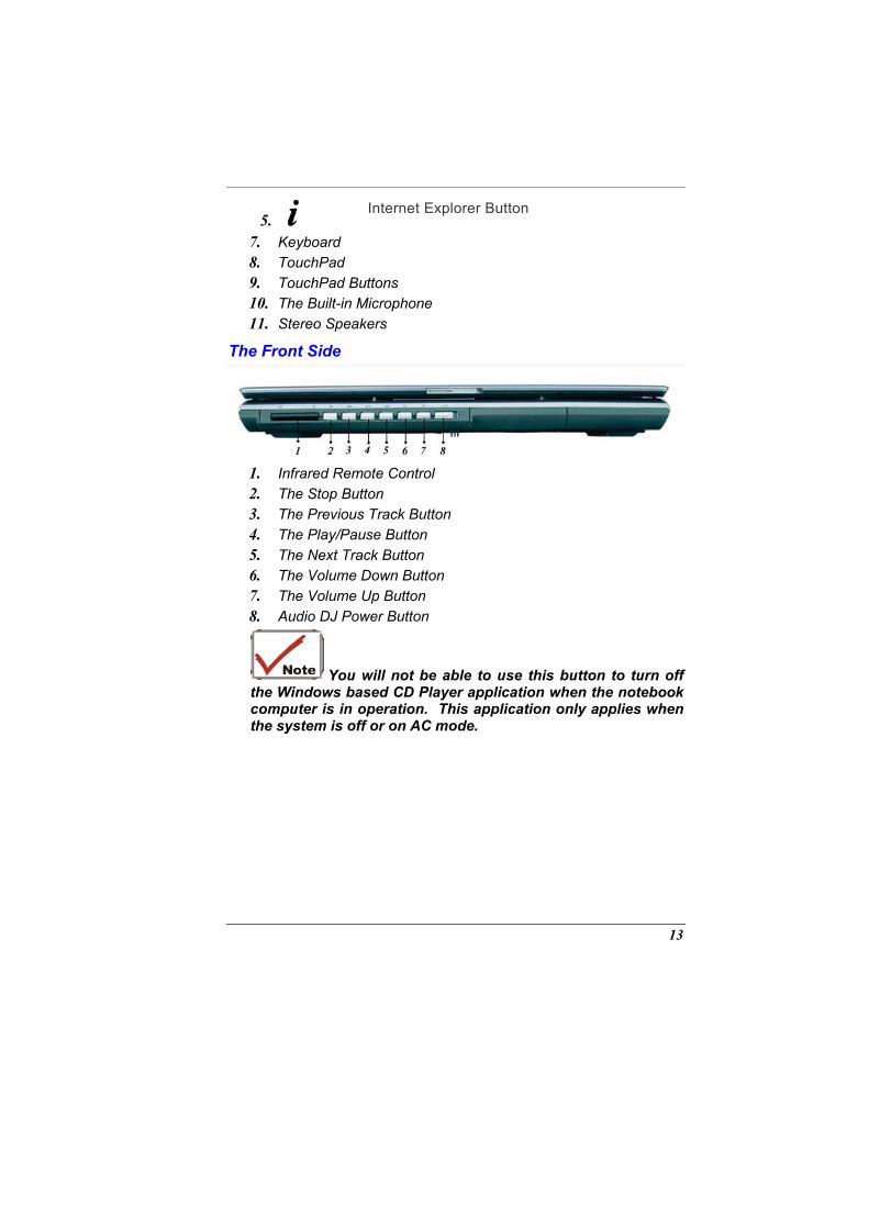
The Front Side
1. 2. 3. 4. 5. 6. 7. 8.
Infrared Remote Control The Stop Button The Previous Track Button The Play/Pause Button The Next Track Button The Volume Down Button The Volume Up Button Audio DJ Power Button
You will not be able to use this button to turn off the Windows based CD Player application when the notebook computer is in operation. This application only applies when the system is off or on AC mode.
13
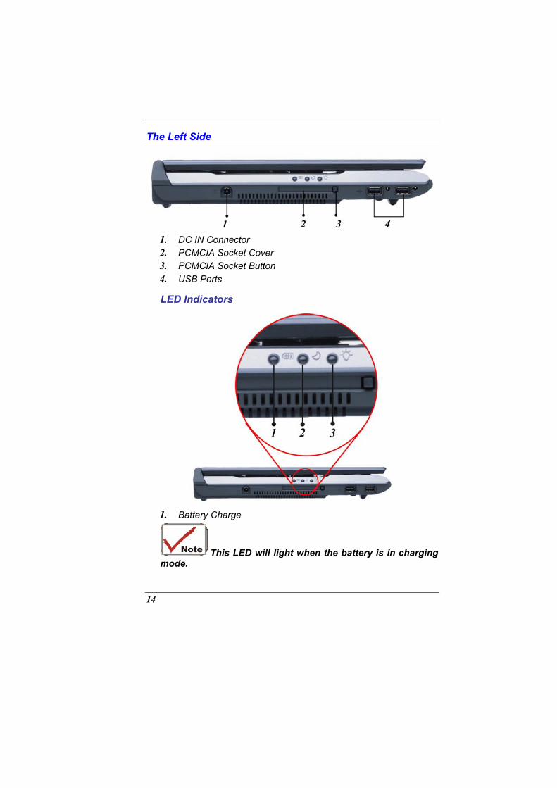
The Left Side
1. 2. 3. 4.
DC IN Connector PCMCIA Socket Cover PCMCIA Socket Button USB Ports
LED Indicators
1. Battery Charge
This LED will light when the battery is in charging mode.
14
2. Suspend
This LED will light when the system is in suspend mode. 3. Power On
This LED will light when the system is power on.
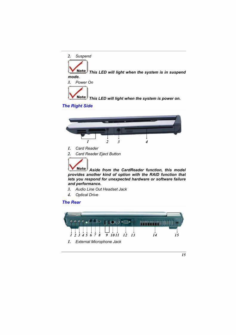
The Right Side
1. 2.
Card Reader Card Reader Eject Button
Aside from the CardReader function, this model provides another kind of option with the RAID function that lets you respond for unexpected hardware or software failure and performance. 3. 4.
Audio Line Out Headset Jack Optical Drive
The Rear
1. External Microphone Jack
15
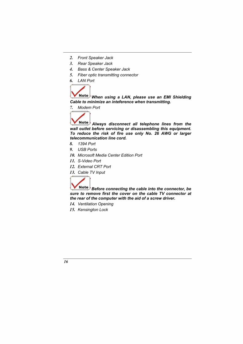
2. 3. 4. 5. 6.
Front Speaker Jack Rear Speaker Jack Bass & Center Speaker Jack Fiber optic transmitting connector LAN Port
When using a LAN, please use an EMI Shielding Cable to minimize an inteference when transmitting. 7. Modem Port
Always disconnect all telephone lines from the wall outlet before servicing or disassembling this equipment. To reduce the risk of fire use only No. 26 AWG or larger telecommunication line cord. 8. 9. 10. 11. 12. 13.
1394 Port USB Ports Microsoft Media Center Edition Port S-Video Port External CRT Port Cable TV Input
Before connecting the cable into the connector, be sure to remove first the cover on the cable TV connector at the rear of the computer with the aid of a screw driver. 14. 15.
Ventilation Opening Kensington Lock
16
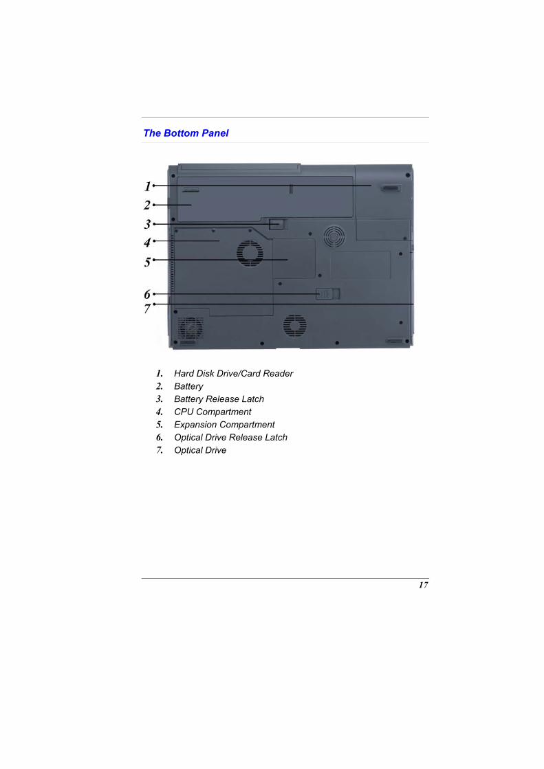
The Bottom Panel
1. 2. 3. 4. 5. 6. 7.
Hard Disk Drive/Card Reader Battery Battery Release Latch CPU Compartment Expansion Compartment Optical Drive Release Latch Optical Drive
17

Page intentionally left blank
18
GETTING STARTED
Connecting to a Power Source
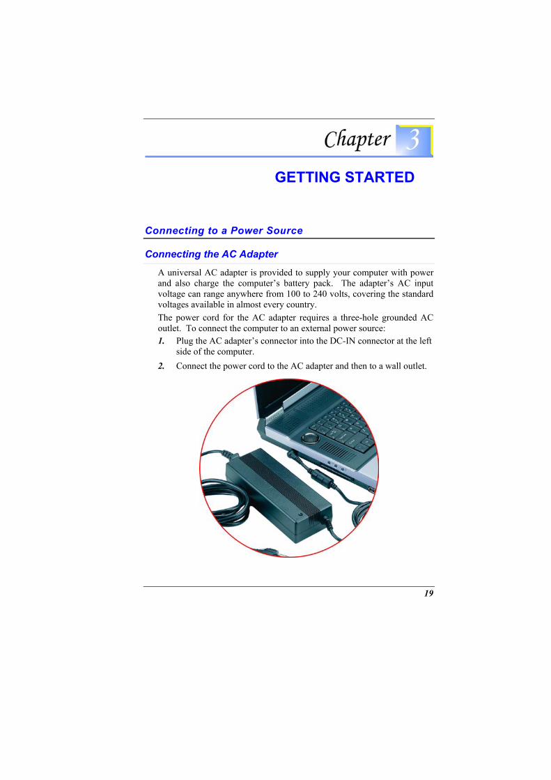
Connecting the AC Adapter
A universal AC adapter is provided to supply your computer with power and also charge the computer’s battery pack. The adapter’s AC input voltage can range anywhere from 100 to 240 volts, covering the standard voltages available in almost every country. The power cord for the AC adapter requires a three-hole grounded AC outlet. To connect the computer to an external power source: 1.
2.
Plug the AC adapter’s connector into the DC-IN connector at the left side of the computer. Connect the power cord to the AC adapter and then to a wall outlet.
19
The best kind of AC power source to connect your Notebook to is a UPS (Uninterruptible Power Supply). Lacking this, use a power strip with a built-in surge protector. Do not use inferior extension cords as this may result in damage to your Notebook. The Notebook comes with its own AC adapter. Do not use a different adapter to power the computer and other electrical devices. Whenever possible, keep the AC adapter plugged into the Notebook and an electrical outlet to recharge the battery.
Never turn off or reset your Notebook while the hard disk is in use and the HDD status icon is lit; doing so can result in loss or destruction of your data. Always wait at least 5 seconds after turning off your Notebook before turning it back on; turning the power on and off in rapid succession can damage the Notebook’s electrical circuitry.
Turning On Your Notebook Computer
Turn on your Notebook by pressing the power button. Hold the button down for a 1 or 2 secon and release. The Power-On Self Test (POST) runs automatically. After the POST is completed, the computer reads the operating system from the hard disk drive into computer memory (this is commonly referred to as “booting” a computer). If your OS (Operating System such as Windows XP etc) is installed, it should start automatically. To turn the Notebook off, save your work and close all open applications, click on Start, then select the “Turn off the computer”. A selection box will be displayed and click on the “Turn Off” button to shut down your computer.
When your computer hangs up, press the power button for 4-6 seconds to shut down the computer.
20
Operating on Battery Power
Your computer comes with a rechargeable battery pack that lets you operate the computer without an external power source. When the battery pack is fully charged, you can operate the computer for approximately 2.5 hours under the following conditions: • The battery pack initially has a full charge. • No peripheral devices are installed. • The disk/DVD-ROM drives run no more than 10% of the time.
Only use batteries that are approved by an authorized dealer for this model only. All batteries are not the same and therefore should not be treated as such. Using the wrong battery could cause serious damage to your computer and yourself through toxic emissions.
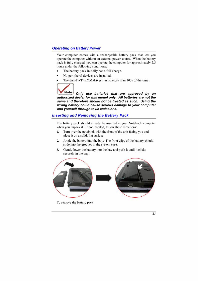
Inserting and Removing the Battery Pack
The battery pack should already be inserted in your Notebook computer when you unpack it. If not inserted, follow these directions: 1.
2.
3.
Turn over the notebook with the front of the unit facing you and place it on a solid, flat surface. Angle the battery into the bay. The front edge of the battery should slide into the grooves in the system case. Gently lower the battery into the bay and push it until it clicks securely in the bay.
To remove the battery pack:
21
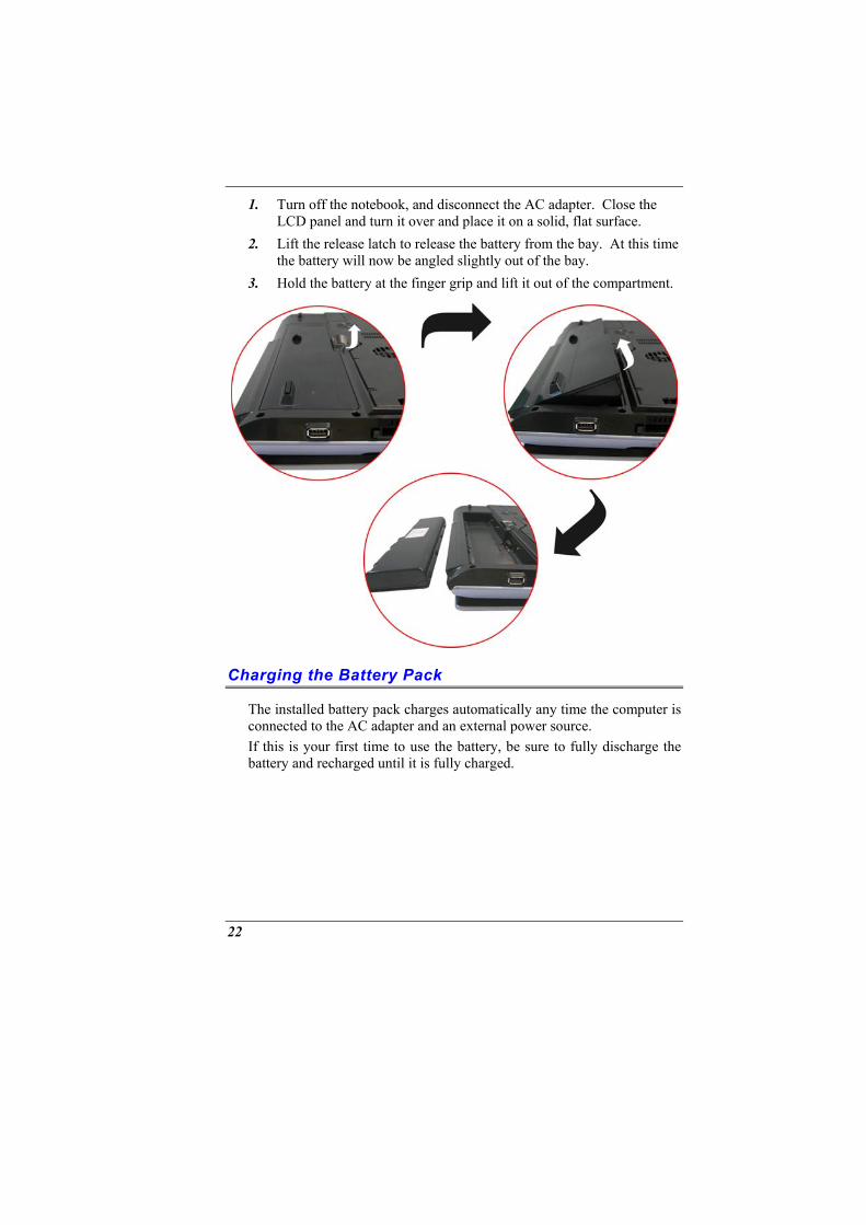
1.
2.
3.
Turn off the notebook, and disconnect the AC adapter. Close the LCD panel and turn it over and place it on a solid, flat surface. Lift the release latch to release the battery from the bay. At this time the battery will now be angled slightly out of the bay. Hold the battery at the finger grip and lift it out of the compartment.
Charging the Battery Pack
The installed battery pack charges automatically any time the computer is connected to the AC adapter and an external power source. If this is your first time to use the battery, be sure to fully discharge the battery and recharged until it is fully charged.
22
USING THE NOTEBOOK
COMPUTER
Adjusting the LCD Screen Display
The LCD screen display can be adjusted by the following key combinations.
KEYS FUNCTIONS [Fn] + [F7] Decreases the brightness level. [Fn] + [F8] Increases the brightness level. [Fn] + [F10] Use this key combination to expand your video
screen or toggle to its original size. [Fn] + [F12] This key combination toggles the display between
the LCD, CRT, simultaneous LCD/CRT, simultaneous LCD/TV, simultaneous LCD/CRT/TV.
LCD Care
LCD screens are delicate devices that need careful handling. Please pay attention to the following precautions: • When you are not using the computer, keep the LCD screen closed
to protect it from dust. • If you need to clean your LCD screen, use a soft tissue to gently
wipe the LCD surface. • Do not put your fingers or sharp objects directly on the surface and
never spray cleaner directly onto the display. • Do not press on, or store any objects on the cover when it is closed.
Doing so may cause the LCD to break.
23

External CRT Display
You can hook up an external monitor through the 15-pin CRT connector. • LCD only • CRT only • Simultaneous display of the LCD screen and CRT monitor • Simultaneous display of the LCD screen and TV screen • Simultaneous display of the TV screen, CRT monitor and LCD
screen You can switch between these display configurations by pressing the key combination [Fn] + [F12]. For information on connecting an external display, please refer to Chapter Four.
A Tour of the Notebook’s Keyboard
The Notebook’s keyboard uses a standard QWERTY layout with the addition of special function keys and an embedded numeric keypad for number intensive data entry. Your keyboard supports Windows by incorporating the two Windows specific keys. With the two Windows keys you will be able to access and take advantage of many of the timesaving features of Windows software. The function keys (F1-F12) on the top row of the keyboard, serve different purposes and carry out different tasks depending on the application you are running. The cursor (arrow) keys (which are all located in the lower right corner of your keyboard) and the [PgUp], [PgDn], [Home] and [End] keys (which are located along the right edge of the keyboard) allow you to move the active cursor of the computer to various locations on the screen or within the document. The embedded numeric keypad consists of 15 keys that make number intensive input more convenient. Like the [Num Lock] key, these keys are labeled in blue on the keycaps. Numeric assignments are located at the upper right of each key. When the numeric keypad is engaged, the NumLock icon will appear in the System Window. The keypad is activated by pressing the [Fn] + [NumLk] key. If an external keyboard is connected, pressing the NumLock key on either the Notebook or external keyboard will enable/disable NumLock of both keyboards in unison.
24
To disable the Notebook numeric keypad while keeping the keypad on an external keyboard activated, use the [Fn] + [NumLk] hot key on the Notebook keyboard.
The Notebook’s Hot Key Controls
KEYS FUNCTION(S) Power Button Press this button once to power on or enter
the suspend/resume mode. Press this button for more than 4 seconds to power off the system.
[Fn] + [F2] This key combination turns on/off the volume.
[Fn] + [F3] Decreases the speaker volume. [Fn] + [F4] Increases the speaker volume. [Fn] + [F7] Decreases the brightness level. [Fn] + [F8] Increases the brightness level. [Fn] + [F10] Use this key combination to expand your
video screen or reset to its original size. [Fn] + [F12] This key combination toggles the display
between the LCD, CRT, simultaneous LCD/CRT, simultaneous LCD/TV, simultaneous LCD/CRT/TV.
Launch Button
KEYS FUNCTION(S) TV Button Press this button to open the TV function.
(Launch the InterVideo WinDVR application) DVD Button Press this button to open the DVD player for
playing any DVD file (Launch the InterVideo WinDVD application)
Music Button Press this button to open the Music application in playing any music file (Launch the InterVideo WinRIP application)
Internet Button
Open the Microsoft’s IE Internet Explorer
25
KEYS FUNCTION(S) Email Button Open the Microsoft’s Outlook
The TouchPad
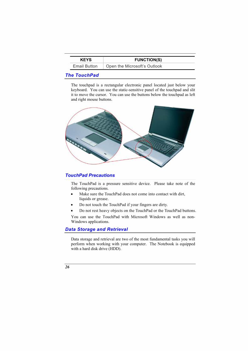
The touchpad is a rectangular electronic panel located just below your keyboard. You can use the static-sensitive panel of the touchpad and slit it to move the cursor. You can use the buttons below the touchpad as left and right mouse buttons.
TouchPad Precautions
The TouchPad is a pressure sensitive device. Please take note of the following precautions. • Make sure the TouchPad does not come into contact with dirt,
liquids or grease. • Do not touch the TouchPad if your fingers are dirty. • Do not rest heavy objects on the TouchPad or the TouchPad buttons. You can use the TouchPad with Microsoft Windows as well as non-Windows applications.
Data Storage and Retrieval
Data storage and retrieval are two of the most fundamental tasks you will perform when working with your computer. The Notebook is equipped with a hard disk drive (HDD).
26
The HDD is removable allowing for easy upgrades.
The DVD-ROM/Combo
Features of the DVD-ROM/Combo Module The features of the DVD-ROM/Combo drive are listed below. • The Audio Play feature allows you to play music CDs • Front panel load/unload button • Supports CD-DA, DVD-ROM mode 1 and mode 2, Multi-Session
Photo CD™, CD-I/Video CD (pcs.) • Low power consumption • 12.7mm height
Precautions for Handling DVD-ROM/Combo Discs • Always hold the disc by the edges, avoid touching the surface. • Use a clean, dry, cloth to remove dust, smudges, or fingerprints.
Wipe from the center outward. • Do not write or place objects on the surface of the disc. • Store discs in a cool dry place not to damage the disc. • Do not use benzene, thinners, or cleaners with detergent. Only use
DVD-ROM cleaning kits. • Do not bend or drop the discs.
PCMCIA Cards and Expansion Sockets
The Notebook features one PCMCIA expansion socket design to interface with one Type II card.
Inserting a PCMCIA Card The computer will emit a medium tone followed by a high tone when a PC card is inserted. When you eject a card, the computer will emit a high tone followed by a medium tone. You can insert and remove a PC card whether the computer is turned On or Off. Follow these instructions to insert a PCMCIA card: 1.
2.
Hold the PCMCIA card with the arrow side up and the connector side toward the socket. Align the card connectors with the socket and carefully slide into the socket until it locks into place.
27
The system will beep once to indicate that it has detected the PC card. To remove a PC card push the eject button, the button will pop-out, push the button again to eject the PCMCIA. When inserting a Type II PC card, make sure the connector is inserted in the socket. Before ejecting a PC card, ensure that it is not being accessed by the System. For example, if the message “Write protect error writing Drive x” is displayed, the user has to change the write protect switch setting on the memory card. To change the switch setting, (a) eject the card, (b) change the switch setting, and (c) re-insert the card. Always disconnect all telephone lines from the wall outlet before servicing or disassembling this equipment. To reduce the risk of fire, use only No. 26 AWG or larger telecommunication line cord.
Power Saving Modes
This section contains information on the Notebook’s power system, including the AC Adapter, the battery system, recharging the battery, and tips for conserving battery power. The power system is comprised of two parts, the AC Adapter and the battery system. The AC Adapter converts AC power from a wall outlet to the DC power required by the computer.
The Battery Power System
A fully charged pack will provide approximately 2.5 hours (Prescott 2.8GHz CPU, power saving mode runs battery mark 4.0.1) of battery life depending on your system configuration application it runs. Before using the computer on battery power for the first time, check the battery status icon on the Windows Toolbar to make sure the battery is fully charged. See Battery Status later in this section for a description and explanation of the Windows Battery icon. Charging the battery takes about 4 hours to charge when the system is in off state. If possible, always charge the battery completely.
Removing the Battery Pack
To remove the battery pack from its compartment, please refer to Chapter Three, Inserting and Removing the Battery Pack.
28
Preparing the Battery Pack for Use Before using the battery pack for the first time, the Smart Battery IC within the battery pack should be calibrated in order to get accurate reporting of remaining battery life status. To calibrate the battery pack follows the instructions below: 1.
2.
3.
4.
Insert the battery into the battery compartment and turn on the Notebook. If the battery is completely without power go to the next step. Otherwise, let the battery run down until the battery low-low warning beeps are heard. The system will automatically enter Suspend mode. Turn the Notebook off. Connect the AC adapter and let the battery fully recharge. When the battery charge indicator turns off, the battery is fully charged. Turn On the notebook, let the battery run down until the battery is in low-low state and you hear a warning beeps. The system will automatically enter the Suspend mode. You can now connect the AC adapter. The battery pack is now calibrated properly.
In general, using the battery until the low-low battery-warning indicator appears and fully recharges the battery each time (full discharge/charge cycle) will ensure the accurate reporting of the battery gauge status.
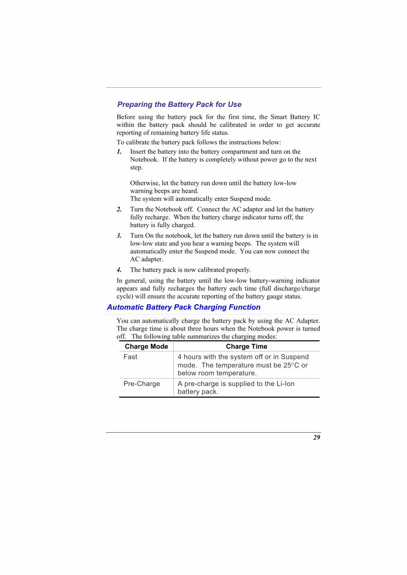
Automatic Battery Pack Charging Function
You can automatically charge the battery pack by using the AC Adapter. The charge time is about three hours when the Notebook power is turned off. The following table summarizes the charging modes:
Charge Mode Charge Time Fast 4 hours with the system off or in Suspend
mode. The temperature must be 25°C or below room temperature.
Pre-Charge A pre-charge is supplied to the Li-Ion battery pack.
29
Battery Status Windows XP has an applet in the Control Panel that will display an icon in the Windows taskbar indicating when the Notebook is running on battery power or is attached to the AC adapter. This applet also displays a meter that indicates how much charge is remaining in the battery.
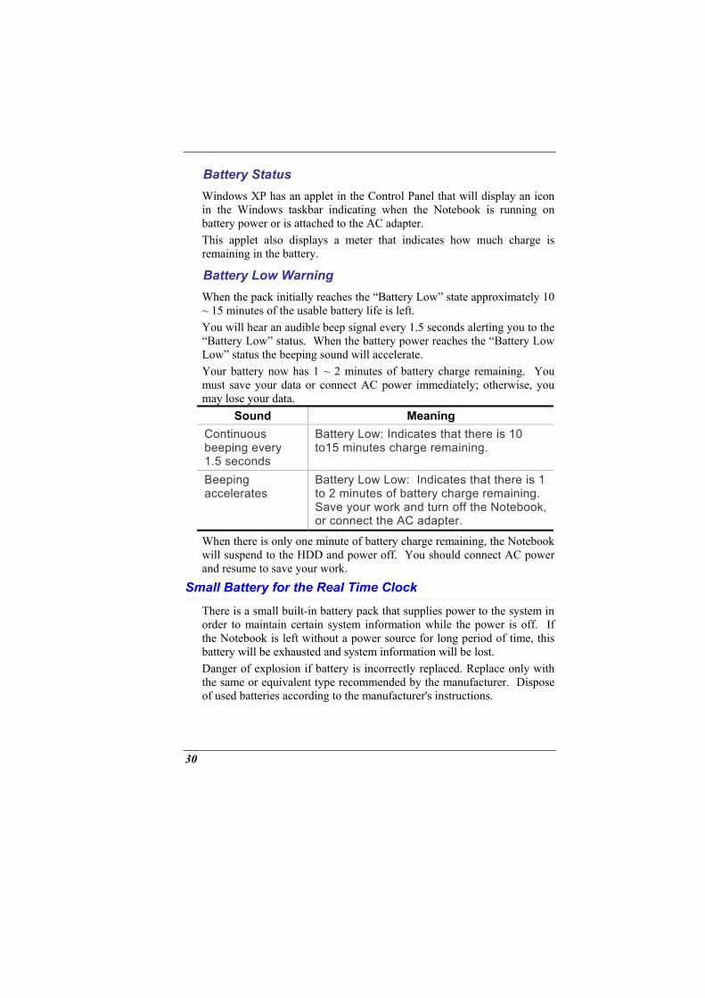
Battery Low Warning When the pack initially reaches the “Battery Low” state approximately 10 ~ 15 minutes of the usable battery life is left. You will hear an audible beep signal every 1.5 seconds alerting you to the “Battery Low” status. When the battery power reaches the “Battery Low Low” status the beeping sound will accelerate. Your battery now has 1 ~ 2 minutes of battery charge remaining. You must save your data or connect AC power immediately; otherwise, you may lose your data.
Sound Meaning Continuous beeping every 1.5 seconds
Battery Low: Indicates that there is 10 to15 minutes charge remaining.
Beeping accelerates
Battery Low Low: Indicates that there is 1 to 2 minutes of battery charge remaining. Save your work and turn off the Notebook, or connect the AC adapter.
When there is only one minute of battery charge remaining, the Notebook will suspend to the HDD and power off. You should connect AC power and resume to save your work.
Small Battery for the Real Time Clock
There is a small built-in battery pack that supplies power to the system in order to maintain certain system information while the power is off. If the Notebook is left without a power source for long period of time, this battery will be exhausted and system information will be lost. Danger of explosion if battery is incorrectly replaced. Replace only with the same or equivalent type recommended by the manufacturer. Dispose of used batteries according to the manufacturer's instructions.
30

Never remove the battery pack while the power is on as this may result in data loss when the system loses power.
Resetting the System
After installing a software application package, you may be prompted to reset the system to load the changed operating environment. To reset the system, or “reboot,” press the [Ctrl] + [Alt] + [Delete] keys simultaneously. This is known as “warm boot.” This key combination acts as “software” reset switch when you encounter hardware or software problems, which lock up the Notebook. If this key combination does not shut down the Notebook, you can reset the Notebook by using the Notebook’s power button. Should the Notebook lock up for some reason, pressing this button powers the Notebook off.
Adjusting the Brightness
To adjust the brightness on the LCD screen, press and hold down the [Fn] key in the lower left hand corner of the keyboard and press the [F7] key to reduce the brightness or [F8] to increase the brightness.
31

Page intentionally left blank
32
DESKTOP OPERATION
This chapter discusses those functions of your notebook that are typical of desktop systems.
Audio
The Multimedia Sound System
The Notebook’s built-in audio capabilities allow you to take advantage of a wide range of education and entertainment multimedia software. The Notebook is equipped with internal stereo speakers, a microphone, and input audio ports for external audio units. An external microphone can be connected to the microphone jack. External speakers or headphones can be connected to the Notebook’s audio-out jack. External audio devices can be connected to the Line in jack.
Audio Volume Control
The Notebook is equipped with hot-key volume controls: Pressing the [Fn] + [F3] hot-key combination decreases the audio output volume; press the [Fn] + [F4] hot-key combination increases the audio output volume.
Audio Software
Your notebook comes equipped with an integrated sound system capable of providing you with quality audio sound through the built-in speakers or through external speakers connected via the system ports.
Sound Recording
Your system allows you to record sounds and store them as files using the microphone via the microphone jack on the rear of the notebook computer. Check the Windows Help and Support Center in Windows for information on using the various elements in sound recording.
33
For a high-quality sound, click on the "Volume Control" at the lower right end of your screen. From the Volume Control windows, click on the "Advanced" tab, click and select the "Microphone Boost" item.
Playing Sound Files
Your notebook can play audio files stored in MIDI, WAVE or MP3 file format. Check the Help and Support Center in Windows for information on the functions of the Media Player.
External Speakers and Microphone
The sound system is capable in providing high-quality sound to external speakers and receiving and processing sounds from an external microphone or external sound source.
Connecting Peripheral Devices
Installing the External monitor
This machine allows use of an external monitor. After you have finished installing it, press [FN]+[F12] simultaneously to change the display
Installing the Printer
Simply connect the enclosed cable to connect the notebook computer USB port to the printer. You also have to install the printer driver.
Installing USB Devices
USB devices are Plug & Play, just plug the USB device into any USB port on the notebook computer to use it. There are some exceptions. Some devices will not be supported by the OS. In these cases you follow the instructions in the device’s manual to install the proper drivers in order use the USB devices.
Connecting to the network
Unless you are a technician, we do not recommend that you install to the Ethernet all by yourself. The illustration only shows how to connect the notebook to the network, the actual application and setting should be done following the instructions in the OS manual, or you should ask for a technician’s professional assistance.
34
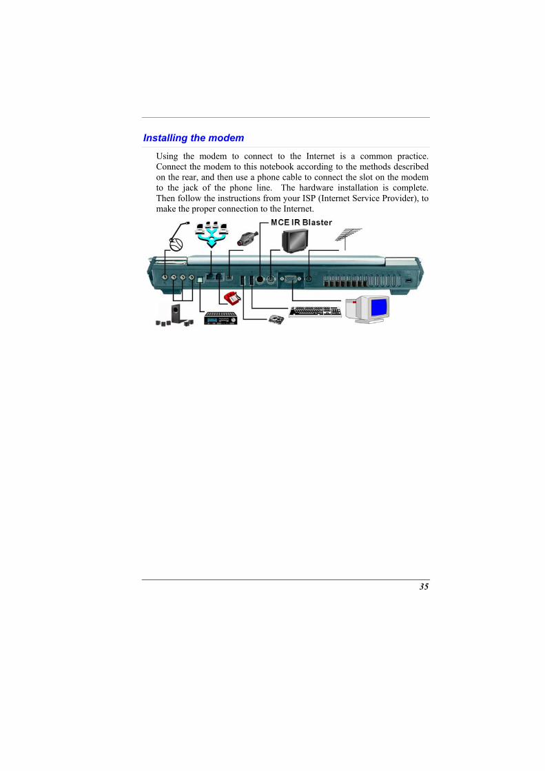
Installing the modem
Using the modem to connect to the Internet is a common practice. Connect the modem to this notebook according to the methods described on the rear, and then use a phone cable to connect the slot on the modem to the jack of the phone line. The hardware installation is complete. Then follow the instructions from your ISP (Internet Service Provider), to make the proper connection to the Internet.
35

36
CONFIGURING AND MAINTAINING
YOUR SYSTEM
Introduction
The BIOS (Basic Input and Output System) Setup program is a menu driven utility that enables you to make changes to the system configuration and tailor your system to reflect installed hardware or alter system performance. When the Notebook is turned back on, the system is configured with the values stored in CMOS. With easy-to-use menus, you can configure such items as: • Hard drives and peripherals • Boot up Drive Sequence • Password protection • Power Management Features The settings made in the BIOS Setup program intimately affect how the Notebook performs.
Navigating through BIOS Setup
The Setup program has been designed to make it as easy to use as possible. If you accidentally make a setting and don’t know which one to switch back to, the Setup program has a hot key that allows you to return to the previous value.
Accessing the BIOS Setup Program
To access the BIOS Setup program, press the DEL key after the Notebook has run through its POST.
37
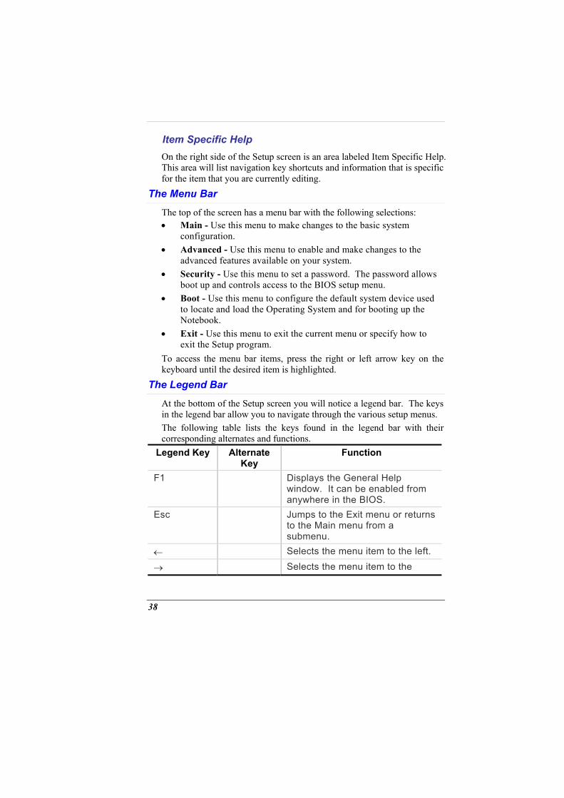
Item Specific Help On the right side of the Setup screen is an area labeled Item Specific Help. This area will list navigation key shortcuts and information that is specific for the item that you are currently editing.
The Menu Bar
The top of the screen has a menu bar with the following selections: • Main - Use this menu to make changes to the basic system
configuration. • Advanced - Use this menu to enable and make changes to the
advanced features available on your system. • Security - Use this menu to set a password. The password allows
boot up and controls access to the BIOS setup menu. • Boot - Use this menu to configure the default system device used
to locate and load the Operating System and for booting up the Notebook.
• Exit - Use this menu to exit the current menu or specify how to exit the Setup program.
To access the menu bar items, press the right or left arrow key on the keyboard until the desired item is highlighted.
The Legend Bar
At the bottom of the Setup screen you will notice a legend bar. The keys in the legend bar allow you to navigate through the various setup menus. The following table lists the keys found in the legend bar with their corresponding alternates and functions.
Legend Key Alternate Key
Function
F1 Displays the General Help window. It can be enabled from anywhere in the BIOS.
Esc Jumps to the Exit menu or returns to the Main menu from a submenu.
← Selects the menu item to the left.
→ Selects the menu item to the
38
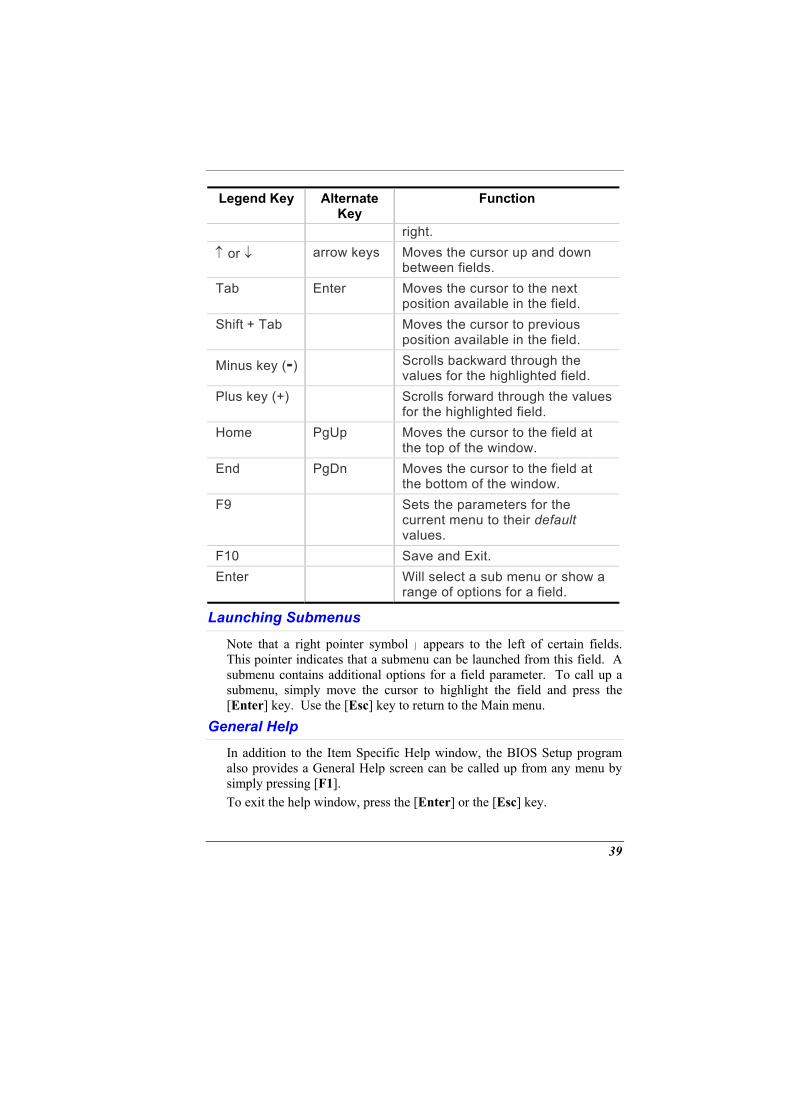
Legend Key Alternate Key
Function
right. ↑ or ↓ arrow keys Moves the cursor up and down
between fields. Tab Enter Moves the cursor to the next
position available in the field. Shift + Tab Moves the cursor to previous
position available in the field.
Minus key (-) Scrolls backward through the values for the highlighted field.
Plus key (+) Scrolls forward through the values for the highlighted field.
Home PgUp Moves the cursor to the field at the top of the window.
End PgDn Moves the cursor to the field at the bottom of the window.
F9 Sets the parameters for the current menu to their default values.
F10 Save and Exit. Enter Will select a sub menu or show a
range of options for a field.
Launching Submenus
Note that a right pointer symbol appears to the left of certain fields. This pointer indicates that a submenu can be launched from this field. A submenu contains additional options for a field parameter. To call up a submenu, simply move the cursor to highlight the field and press the [Enter] key. Use the [Esc] key to return to the Main menu.
General Help
In addition to the Item Specific Help window, the BIOS Setup program also provides a General Help screen can be called up from any menu by simply pressing [F1]. To exit the help window, press the [Enter] or the [Esc] key.
39
Save Changes and Exit the Setup Program Refer to the Exit menu section of this chapter for detailed information on saving changes and exiting the setup program.
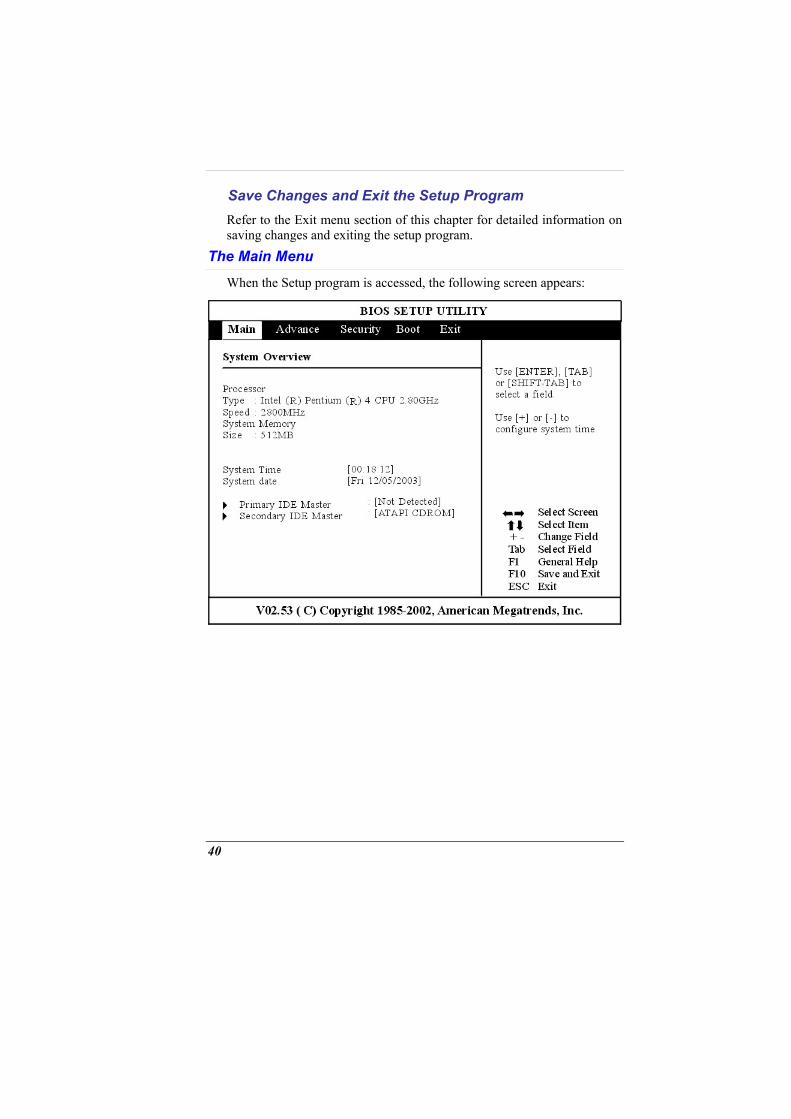
The Main Menu
When the Setup program is accessed, the following screen appears:
40
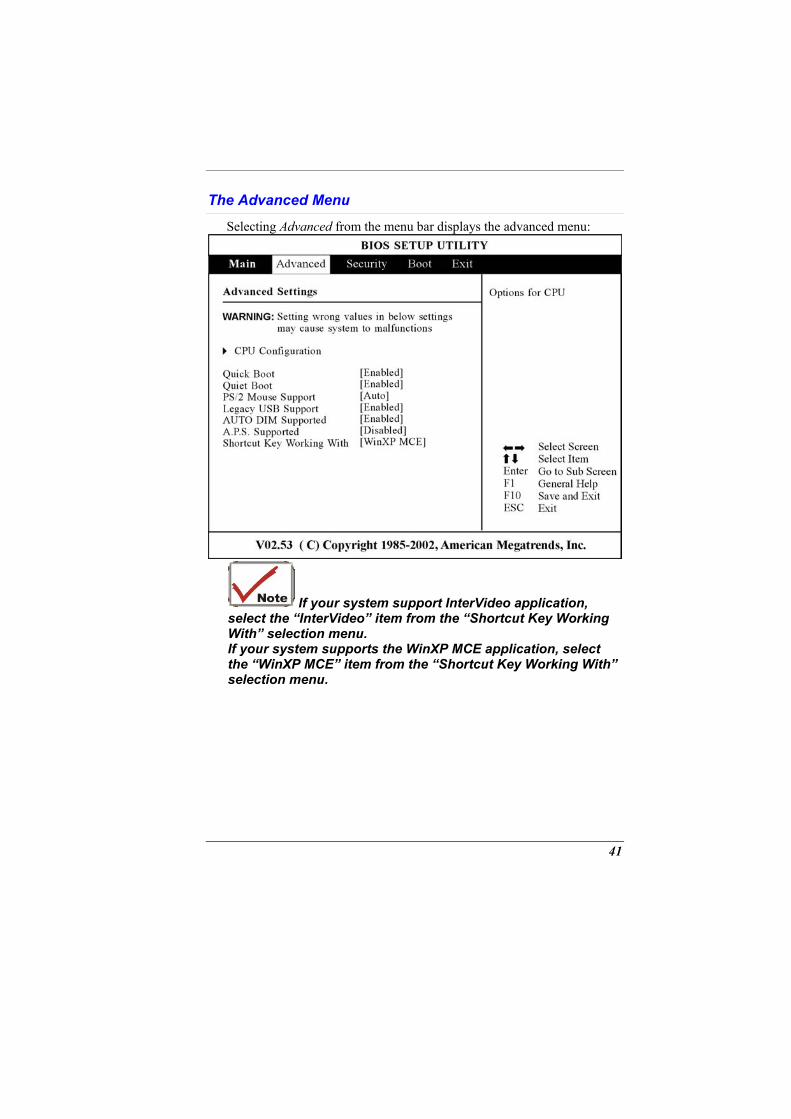
The Advanced Menu
Selecting Advanced from the menu bar displays the advanced menu:
If your system support InterVideo application, select the “InterVideo” item from the “Shortcut Key Working With” selection menu. If your system supports the WinXP MCE application, select the “WinXP MCE” item from the “Shortcut Key Working With” selection menu.
41
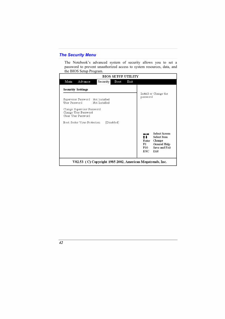
The Security Menu
The Notebook’s advanced system of security allows you to set a password to prevent unauthorized access to system resources, data, and the BIOS Setup Program.
42
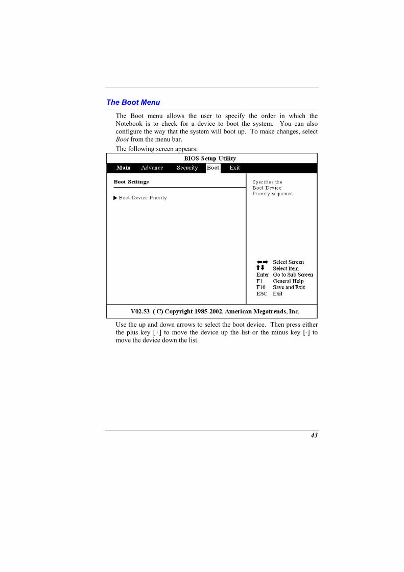
The Boot Menu
The Boot menu allows the user to specify the order in which the Notebook is to check for a device to boot the system. You can also configure the way that the system will boot up. To make changes, select Boot from the menu bar. The following screen appears:
Use the up and down arrows to select the boot device. Then press either the plus key [+] to move the device up the list or the minus key [-] to move the device down the list.
43
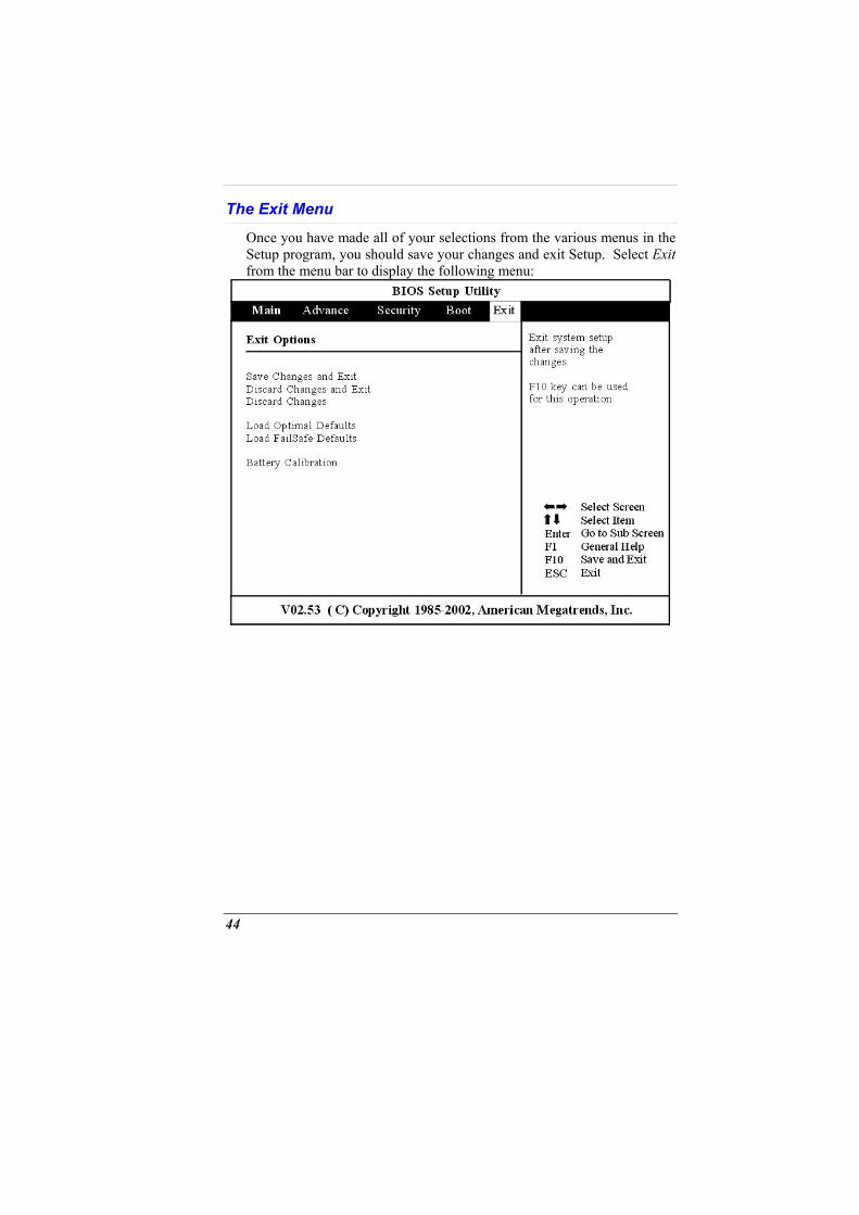
The Exit Menu
Once you have made all of your selections from the various menus in the Setup program, you should save your changes and exit Setup. Select Exit from the menu bar to display the following menu:
44
RAID SETTING (OPTION)
Raid Setting (If Your System Supports RAID)
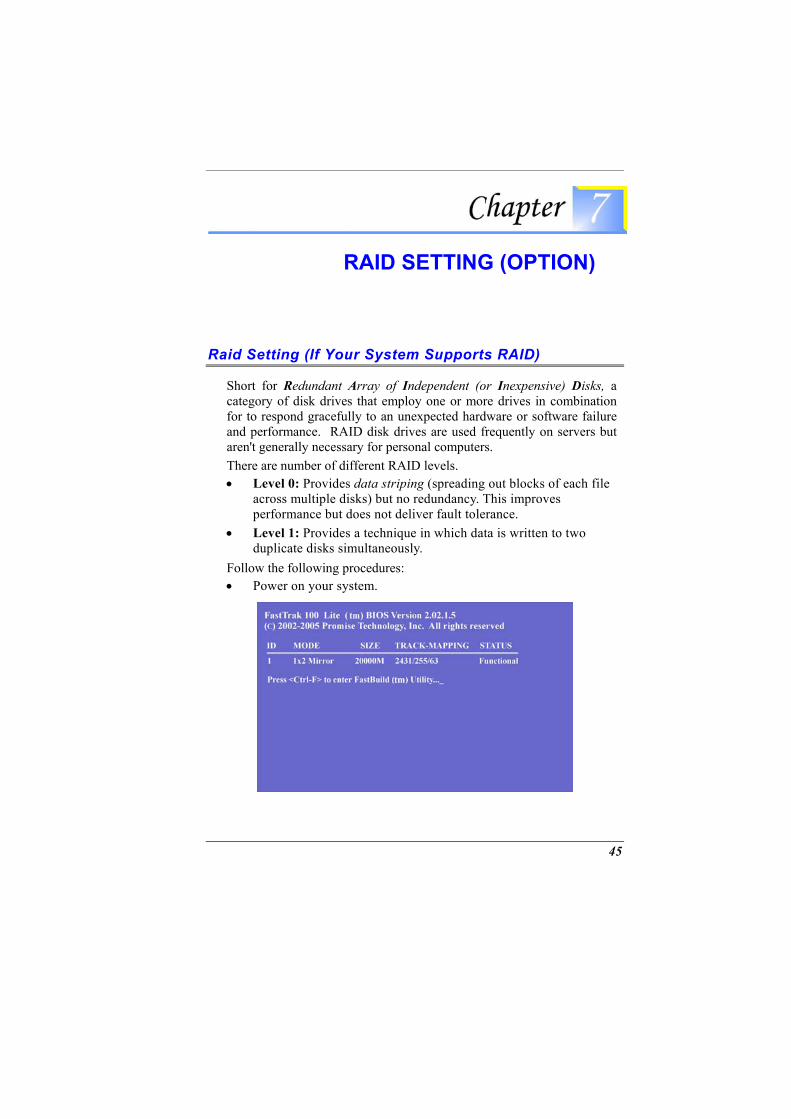
Short for Redundant Array of Independent (or Inexpensive) Disks, a category of disk drives that employ one or more drives in combination for to respond gracefully to an unexpected hardware or software failure and performance. RAID disk drives are used frequently on servers but aren't generally necessary for personal computers. There are number of different RAID levels. • Level 0: Provides data striping (spreading out blocks of each file
across multiple disks) but no redundancy. This improves performance but does not deliver fault tolerance.
• Level 1: Provides a technique in which data is written to two duplicate disks simultaneously.
Follow the following procedures: • Power on your system.
45
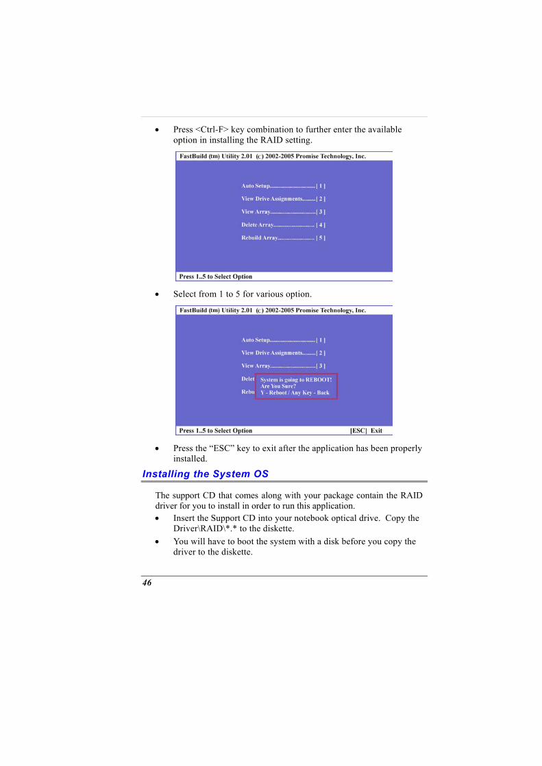
• Press <Ctrl-F> key combination to further enter the available option in installing the RAID setting.
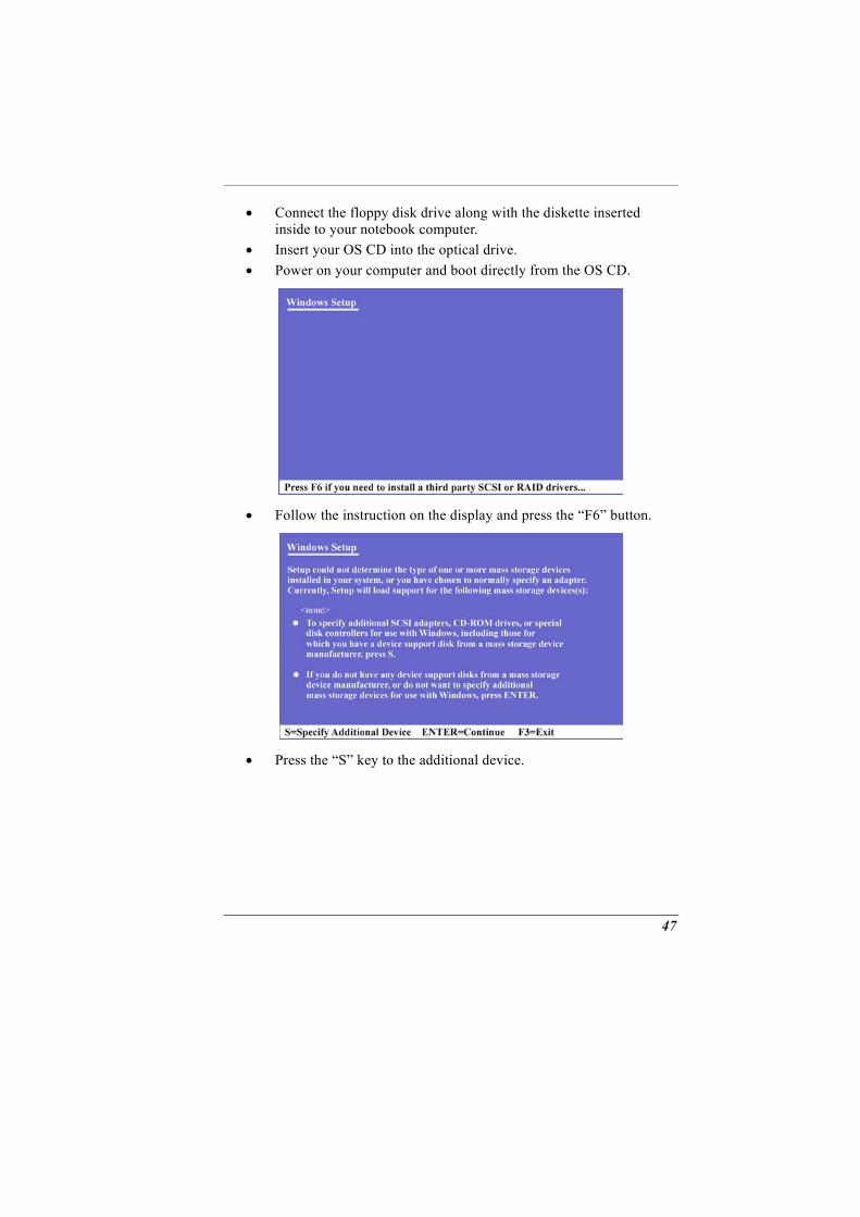
• Select from 1 to 5 for various option.
• Press the “ESC” key to exit after the application has been properly installed.
Installing the System OS
The support CD that comes along with your package contain the RAID driver for you to install in order to run this application. • Insert the Support CD into your notebook optical drive. Copy the
Driver\RAID\*.* to the diskette. • You will have to boot the system with a disk before you copy the
driver to the diskette.
46
• Connect the floppy disk drive along with the diskette inserted inside to your notebook computer.
• Insert your OS CD into the optical drive. • Power on your computer and boot directly from the OS CD.
• Follow the instruction on the display and press the “F6” button.
• Press the “S” key to the additional device.
47
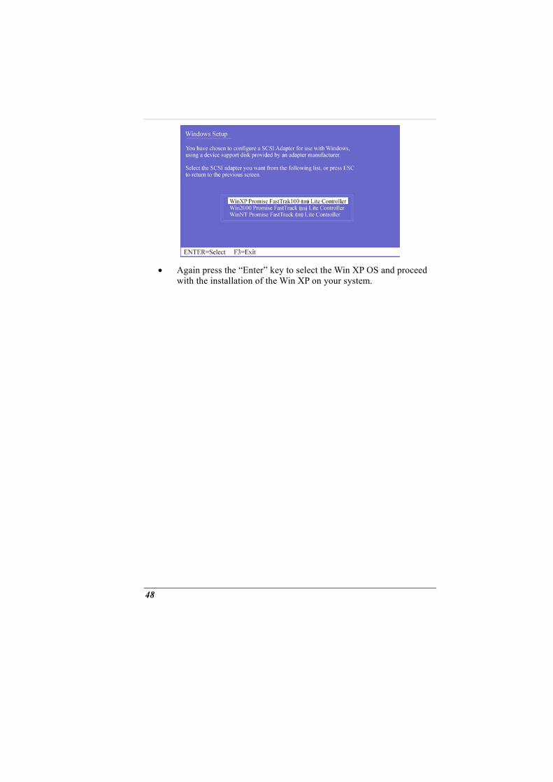
• Again press the “Enter” key to select the Win XP OS and proceed with the installation of the Win XP on your system.
48
MICROSOFT CENTER EDITION
(MCE) (OPTION)
Windows XP Media Center Edition (MCE)
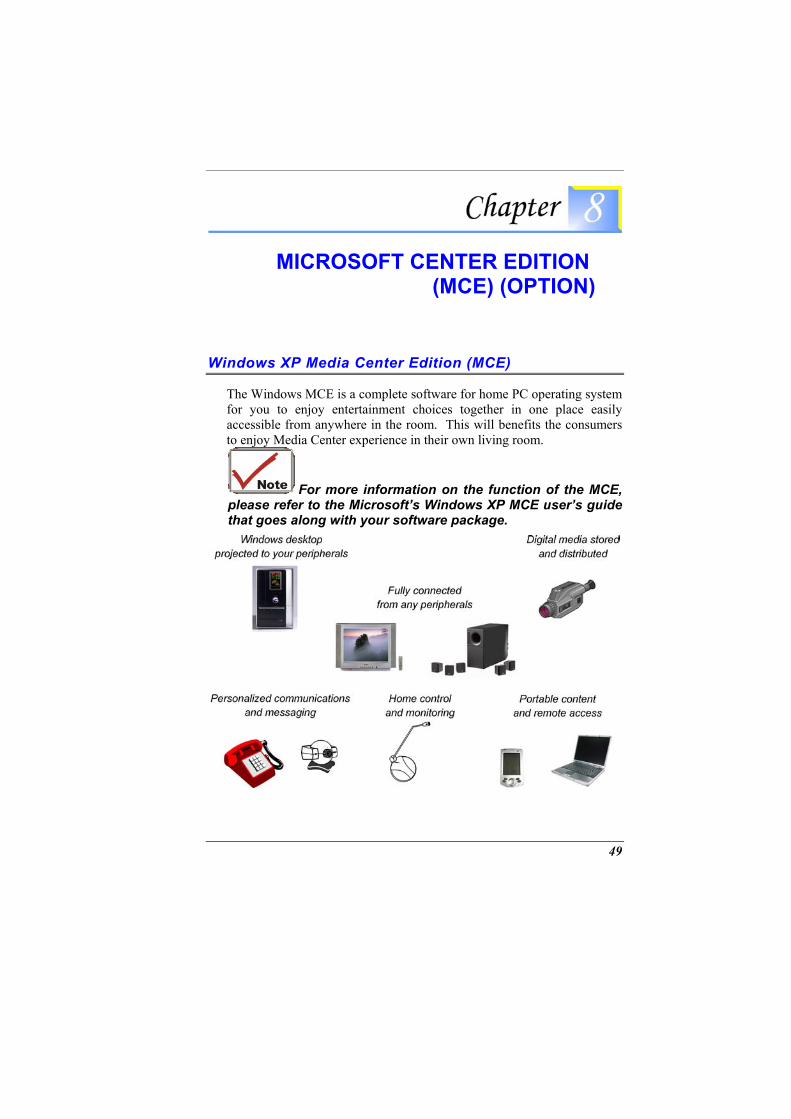
The Windows MCE is a complete software for home PC operating system for you to enjoy entertainment choices together in one place easily accessible from anywhere in the room. This will benefits the consumers to enjoy Media Center experience in their own living room.
For more information on the function of the MCE, please refer to the Microsoft’s Windows XP MCE user’s guide that goes along with your software package.
49

Page intentionally left blank
50
THE SOFTWARE UTILITIES DISKS
There are two separate procedures on how to install the driver: AutoRun installation and Manual installation.
AutoRun Installation
Installing the AGP Driver
Please follow these instructions to install the driver: • Insert the DVD-ROM Driver into your DVD-ROM drive. • Click “Start” and Select “Run”. • Type the following: D:\Driver\AGP\Setup.exe (If D is not your
DVD-ROM drive, substitute D with the correct drive letter). • Click on “Setup” to begin the Installation Wizard. • Follow the Wizard’s on-screen instructions to complete the
installation. • Restart the system.
Installing VGA Display Driver
Please follow these instructions to install the driver: • Insert the DVD-ROM Driver into your DVD-ROM drive. • Click “Start” and Select “Run”. • Type the following: D:\Driver\VGA\ Setup.exe (If D is not your
DVD-ROM drive, substitute D with the correct drive letter). • Click on “Setup” to begin the Installation Wizard. • Follow the Wizard’s on-screen instructions to complete the
installation. • Restart the system.
51
Intalling the Audio Driver
Please follow these instructions to install the driver: • Insert the DVD-ROM Driver into your DVD-ROM drive. • Click “Start” and Select “Run”. • Type the following: D:\Driver\Audio\Setup.exe (If D is not your
DVD-ROM drive, substitute D with the correct drive letter). • Click on “Setup” to begin the Installation Wizard. • Follow the Wizard’s on-screen instructions to complete the
installation. • Restart the system.
Installing the 1000/100/10M LAN Driver
Please follow these instructions to install the driver: • Insert the DVD-ROM Driver into your DVD-ROM drive. • Click “Start” and Select “Run”. • Type the following: D:\Driver\1GLAN\Setup.exe (If D is not your
DVD-ROM drive, substitute D with the correct drive letter). • Click on “Setup” to begin the Installation Wizard. • Follow the Wizard’s on-screen instructions to complete the
installation. • Restart the system.
Installing the CardReader Driver
Please follow these instructions to install the driver: • Insert the DVD-ROM Driver into your DVD-ROM drive. • Click “Start” and Select “Run”. • Type the following: D:\Driver\CardReader\Setup.exe (If D is not
your DVD-ROM drive, substitute D with the correct drive letter). • Click on “Setup” to begin the Installation Wizard. • Follow the Wizard’s on-screen instructions to complete the
installation. • Restart the system.
Installing the TV Tuner Drivers
Please follow these instructions to install the driver:
52
• Insert the DVD-ROM Driver into your DVD-ROM drive. • Click “Start” and Select “Run”. • Type the following: D:\Driver\TVTuner\ Setup.exe (If D is not
your DVD-ROM drive, substitute D with the correct drive letter). • Click on “Setup” to begin the Installation Wizard. • Follow the Wizard’s on-screen instructions to complete the
installation. • Restart the system.
Installing the TouchPad Driver
Please follow these instructions to install the driver: • Insert the DVD-ROM Driver into your DVD-ROM drive. • Click “Start” and Select “Run”. • Type the following: D:\Driver\Touchpad\win2KXP\Setup.exe (If D
is not your DVD-ROM drive, substitute D with the correct drive letter).
• Click on “Setup” to begin the Installation Wizard. • Follow the Wizard’s on-screen instructions to complete the
installation. • Restart the system.
Manual Installation
To install the driver manually, follow the step-by-step procedures described on each individual section for a more clear installation.
Installing the LiteOn/PCTEL Modem Driver
Please follow these instructions to install the driver: • Insert the CD-ROM Driver into your CD-ROM/DVD-ROM drive. • Click “Start” and Select “Run”. • Type the following:
D:\Driver\MDC\LiteOn\Modem\WinXP\Setup.exe (If D is not your CD-ROM/DVD-ROM drive, substitute D with the correct drive letter).
• Click on “Setup” to begin the Installation Wizard. • Follow the Wizard’s on-screen instructions to complete the
installation.
53
• Restart the system.
Installing the Billionton/SmartLink Modem Driver
Please follow these instructions to install the driver: • Insert the CD-ROM Driver into your CD-ROM/DVD-ROM drive. • Click “Start” and Select “Run”. • Type the following:
D:\Driver\MDC\Billionton\Modem\Win2KXP\Setup.exe (If D is not your CD-ROM/DVD-ROM drive, substitute D with the correct drive letter).
• Click on “Setup” to begin the Installation Wizard. • Follow the Wizard’s on-screen instructions to complete the
installation. • Restart the system.
Installing the Actiontec (Qcom)/Agere Modem Driver for Win2KXP
Please follow these instructions to install the driver: Please follow these instructions to install the driver: • Insert the CD-ROM Driver into your CD-ROM/DVD-ROM drive. • Click “Start” and Select “Run”. • Type the following:
D:\Driver\MDC\Actiontec\Modem\Win2KXP\Setup.exe (If D is not your CD-ROM/DVD-ROM drive, substitute D with the correct drive letter).
• Click on “Setup” to begin the Installation Wizard. • Follow the Wizard’s on-screen instructions to complete the
installation. • Restart the system.
Installing the CardBus Driver
Please follow these instructions to install the driver: • From Start, click on the "My Computer" icon and click the "View
System Information". • Click on the "Hardware" tab from the "System Properties" dialog
window. • Click the "Device Manager" button.
54
• Double click on the "PCMCIA adapters" , double click the "Generic CardBus Controller" and click on the "Driver" tab.
• Click the "Update Driver" tab and select the "Install from a list or specific location (Advanced)" item and click "Next".
• Select the "Include this location in the search" item and click on the "Browse" button and specify for the designate location of your CD driver d:\Driver\Cardbus\WinXP to proceed with the installation.
Installing the MiniPCI Wireless LAN Card Driver for WinXP
Please follow these instructions to install the driver: • From Start, click on the "My Computer" icon and click the "View
System Information". • Click on the "Hardware" tab from the "System Properties" dialog
window. • Click the "Device Manager" button. • Double click on the "Other Devices" , double click the " Network
Controller " and click on the "Driver" tab. • Click the "Update Driver" tab and select the "Install from a list or
specific location (Advanced)" item and click "Next". • Select the "Include this location in the search" item and click on
the "Browse" button and specify for the designate location of your CD driver D:\Driver\MiniPCI\Billionton_WLAN\WinXP\ or D:\Driver\MiniPCI\Actiontec_WLAN\LAN_802MIG\2KXP\
55
VGA Utilities
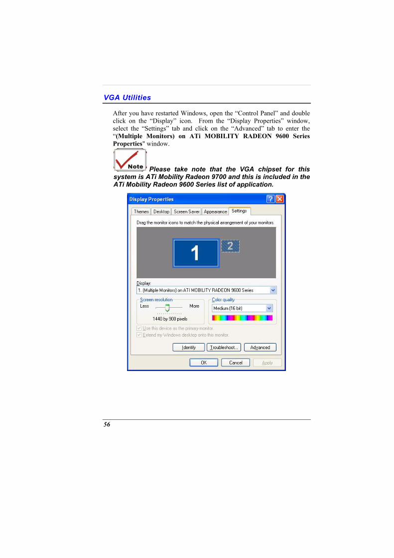
After you have restarted Windows, open the “Control Panel” and double click on the “Display” icon. From the “Display Properties” window, select the “Settings” tab and click on the “Advanced” tab to enter the “(Multiple Monitors) on ATi MOBILITY RADEON 9600 Series Properties" window.
Please take note that the VGA chipset for this system is ATi Mobility Radeon 9700 and this is included in the ATi Mobility Radeon 9600 Series list of application.
56
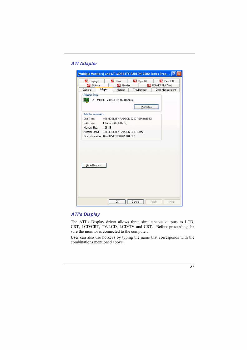
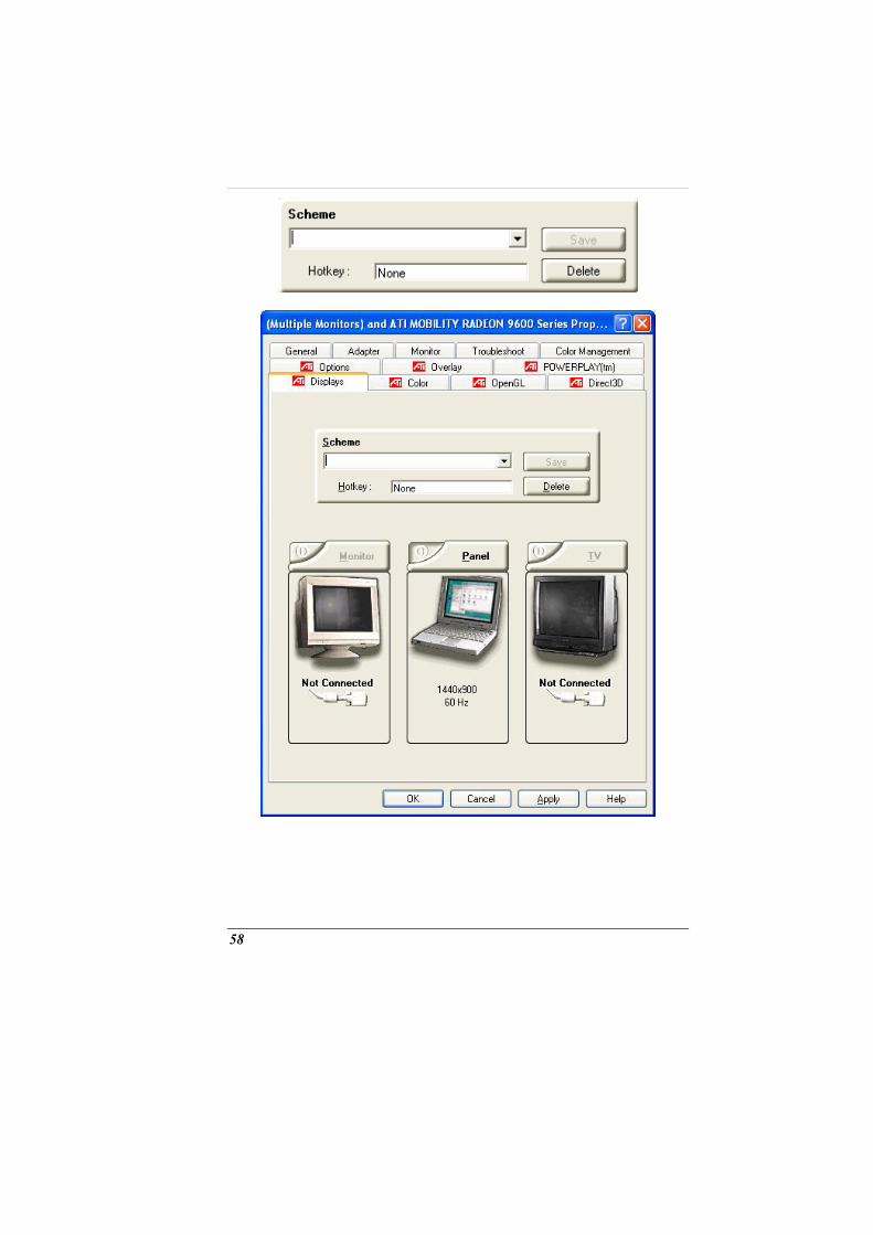
ATI Adapter
ATI’s Display The ATI’s Display driver allows three simultaneous outputs to LCD, CRT, LCD/CRT, TV/LCD, LCD/TV and CRT. Before proceeding, be sure the monitor is connected to the computer. User can also use hotkeys by typing the name that corresponds with the combinations mentioned above.
57
58
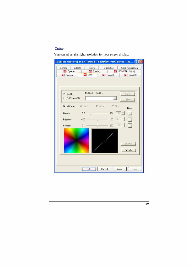
Color You can adjust the right resolution for your screen display.
59
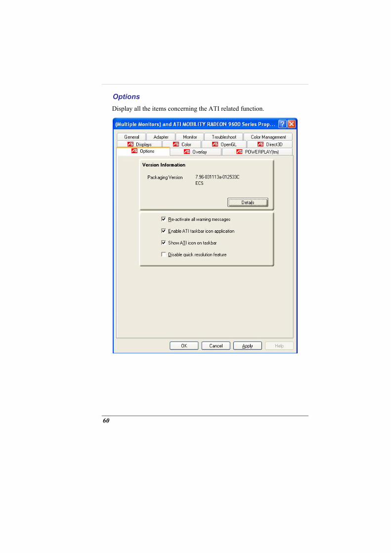
Options Display all the items concerning the ATI related function.
60
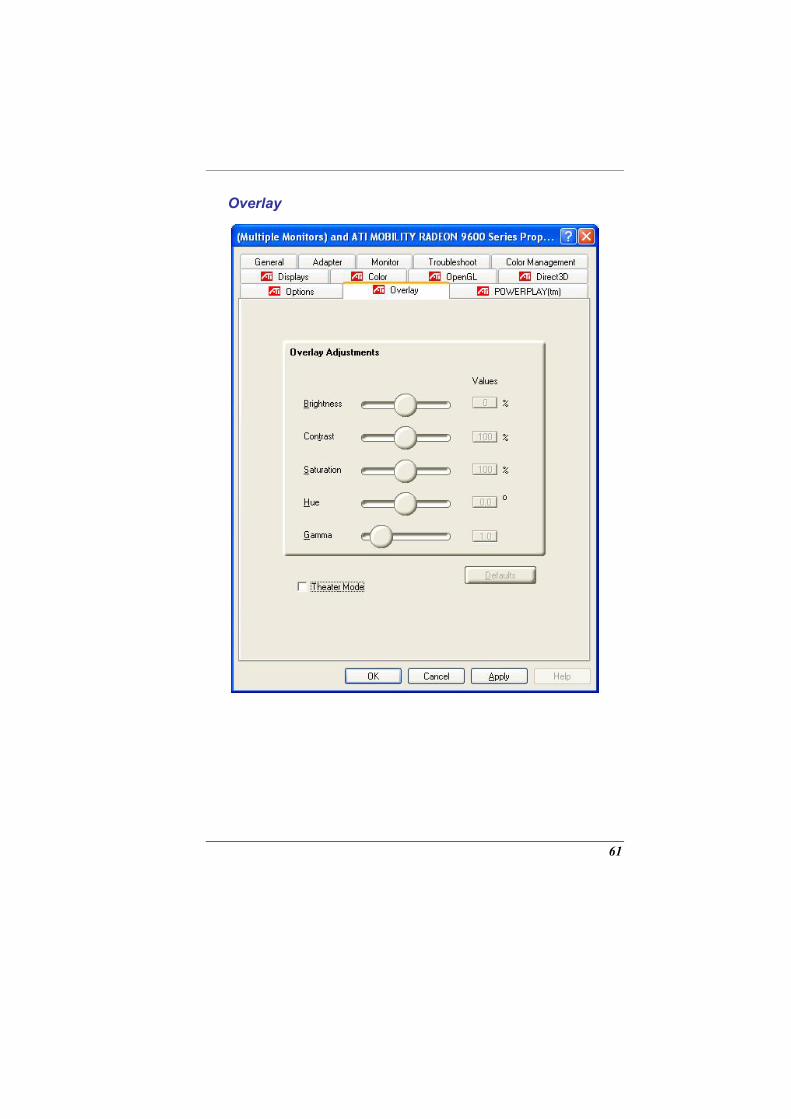
Overlay
61

Page intentionally left blank
62
VIEWING LIVE VIDEO
The Utility allows you to access the entire range of display controls and configuration options. Its live video can co-exist with other applications running at the time. In addition, you have the choice of keeping the default video window size, scaling it to any other size or using the entire screen for video display. You can either sit in front of your monitor, controlling the video with menu commands, toolbar buttons as well as the TV Tuner, or lay back in your chair with the remote control pad in your hand.
For more detailed information on the function for each individual mode on the Remote Control, please refer to the Remote Control Guide user’s manual.
Using the Remote Control
The Remote Control comes with three multimedia softwares: WinDVR, WinDVD, and WinRip. These softwares use only one remote control; the function of each buttons will vary on different software.
63
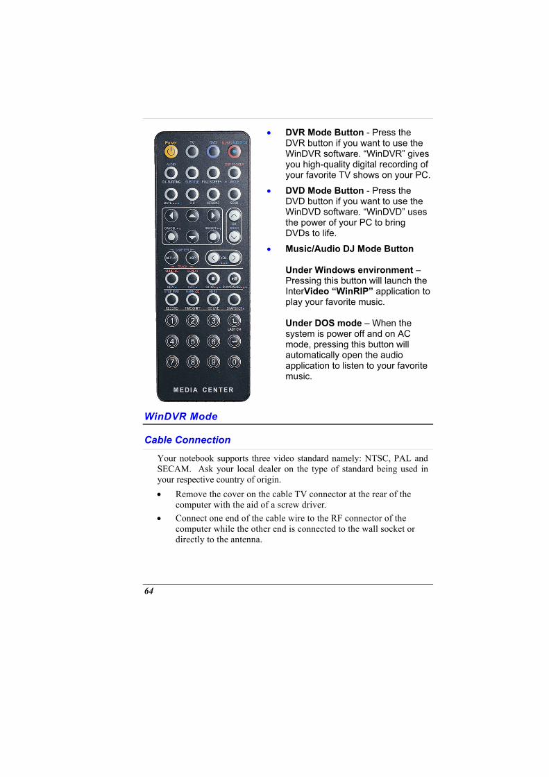
•
•
•
DVR Mode Button - Press the DVR button if you want to use the WinDVR software. “WinDVR” gives you high-quality digital recording of your favorite TV shows on your PC.
DVD Mode Button - Press the DVD button if you want to use the WinDVD software. “WinDVD” uses the power of your PC to bring DVDs to life.
Music/Audio DJ Mode Button Under Windows environment – Pressing this button will launch the InterVideo “WinRIP” application to play your favorite music. Under DOS mode – When the system is power off and on AC mode, pressing this button will automatically open the audio application to listen to your favorite music.
WinDVR Mode
Cable Connection
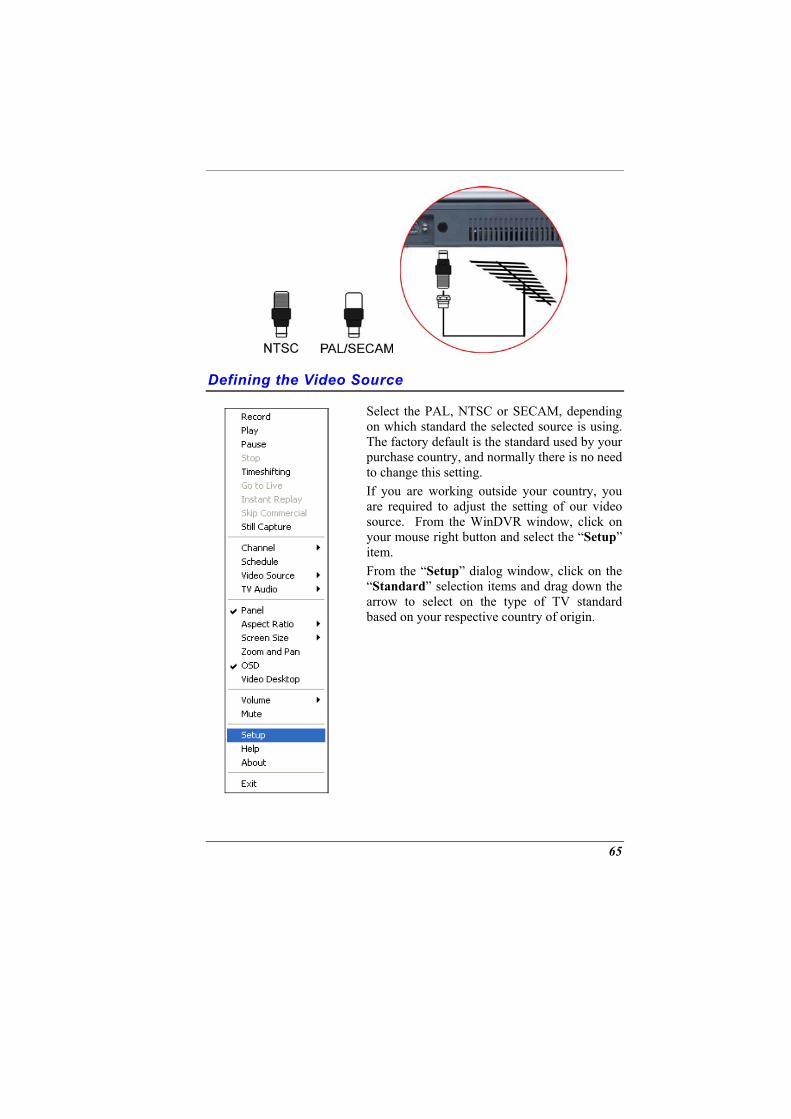
Your notebook supports three video standard namely: NTSC, PAL and SECAM. Ask your local dealer on the type of standard being used in your respective country of origin. • Remove the cover on the cable TV connector at the rear of the
computer with the aid of a screw driver. • Connect one end of the cable wire to the RF connector of the
computer while the other end is connected to the wall socket or directly to the antenna.
64
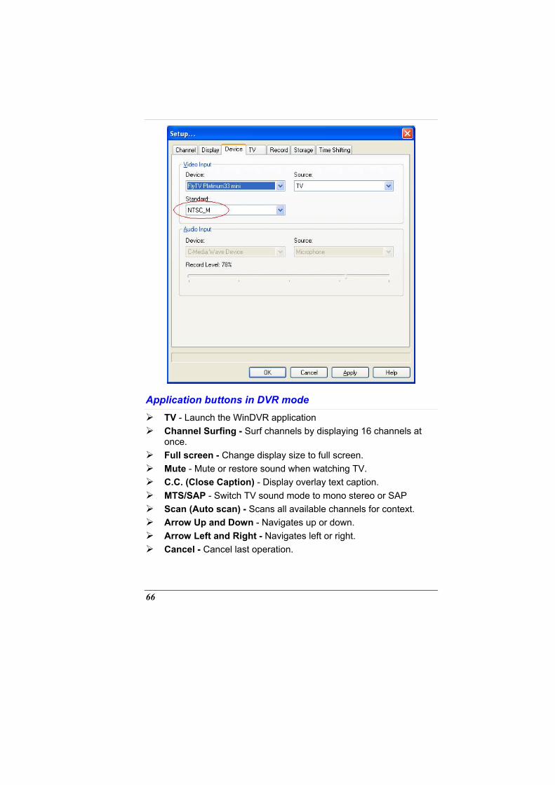
Defining the Video Source
Select the PAL, NTSC or SECAM, depending on which standard the selected source is using. The factory default is the standard used by your purchase country, and normally there is no need to change this setting. If you are working outside your country, you are required to adjust the setting of our video source. From the WinDVR window, click on your mouse right button and select the “Setup” item. From the “Setup” dialog window, click on the “Standard” selection items and drag down the arrow to select on the type of TV standard based on your respective country of origin.
65
Application buttons in DVR mode TV - Launch the WinDVR application Channel Surfing - Surf channels by displaying 16 channels at
once. Full screen - Change display size to full screen. Mute - Mute or restore sound when watching TV. C.C. (Close Caption) - Display overlay text caption. MTS/SAP - Switch TV sound mode to mono stereo or SAP Scan (Auto scan) - Scans all available channels for context. Arrow Up and Down - Navigates up or down. Arrow Left and Right - Navigates left or right. Cancel - Cancel last operation.
66
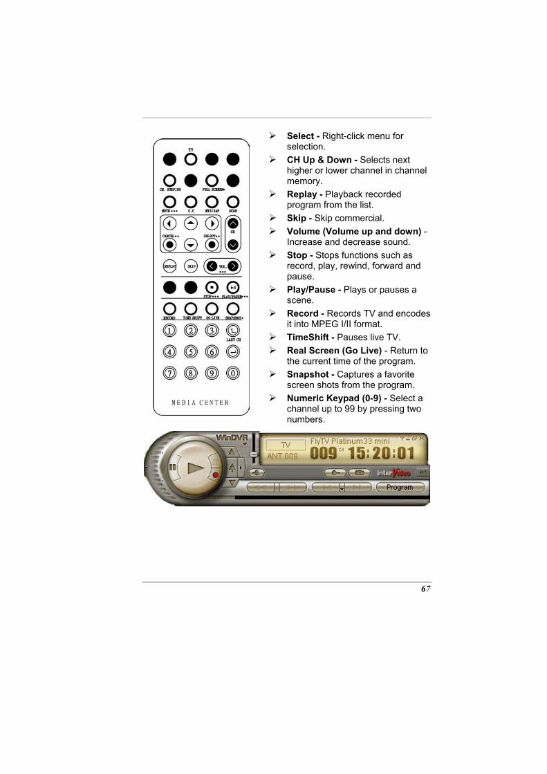
Select - Right-click menu for selection.
CH Up & Down - Selects next higher or lower channel in channel memory.
Replay - Playback recorded program from the list.
Skip - Skip commercial. Volume (Volume up and down) -
Increase and decrease sound. Stop - Stops functions such as
record, play, rewind, forward and pause.
Play/Pause - Plays or pauses a scene.
Record - Records TV and encodes it into MPEG I/II format.
TimeShift - Pauses live TV. Real Screen (Go Live) - Return to
the current time of the program. Snapshot - Captures a favorite
screen shots from the program. Numeric Keypad (0-9) - Select a
channel up to 99 by pressing two numbers.
67
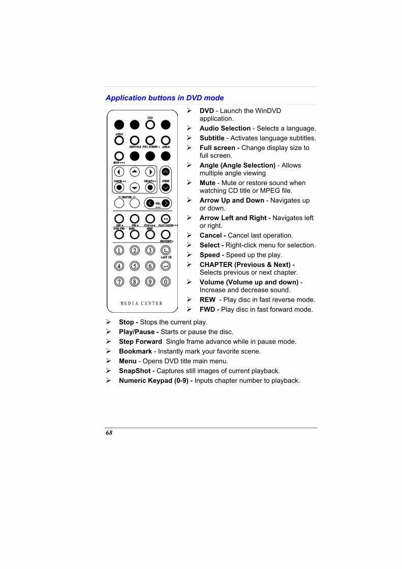
Application buttons in DVD mode DVD - Launch the WinDVD
application. Audio Selection - Selects a language. Subtitle - Activates language subtitles. Full screen - Change display size to
full screen. Angle (Angle Selection) - Allows
multiple angle viewing Mute - Mute or restore sound when
watching CD title or MPEG file. Arrow Up and Down - Navigates up
or down. Arrow Left and Right - Navigates left
or right. Cancel - Cancel last operation. Select - Right-click menu for selection. Speed - Speed up the play. CHAPTER (Previous & Next) -
Selects previous or next chapter. Volume (Volume up and down) -
Increase and decrease sound. REW - Play disc in fast reverse mode. FWD - Play disc in fast forward mode.
Stop - Stops the current play. Play/Pause - Starts or pause the disc. Step Forward Single frame advance while in pause mode. Bookmark - Instantly mark your favorite scene. Menu - Opens DVD title main menu. SnapShot - Captures still images of current playback. Numeric Keypad (0-9) - Inputs chapter number to playback.
68
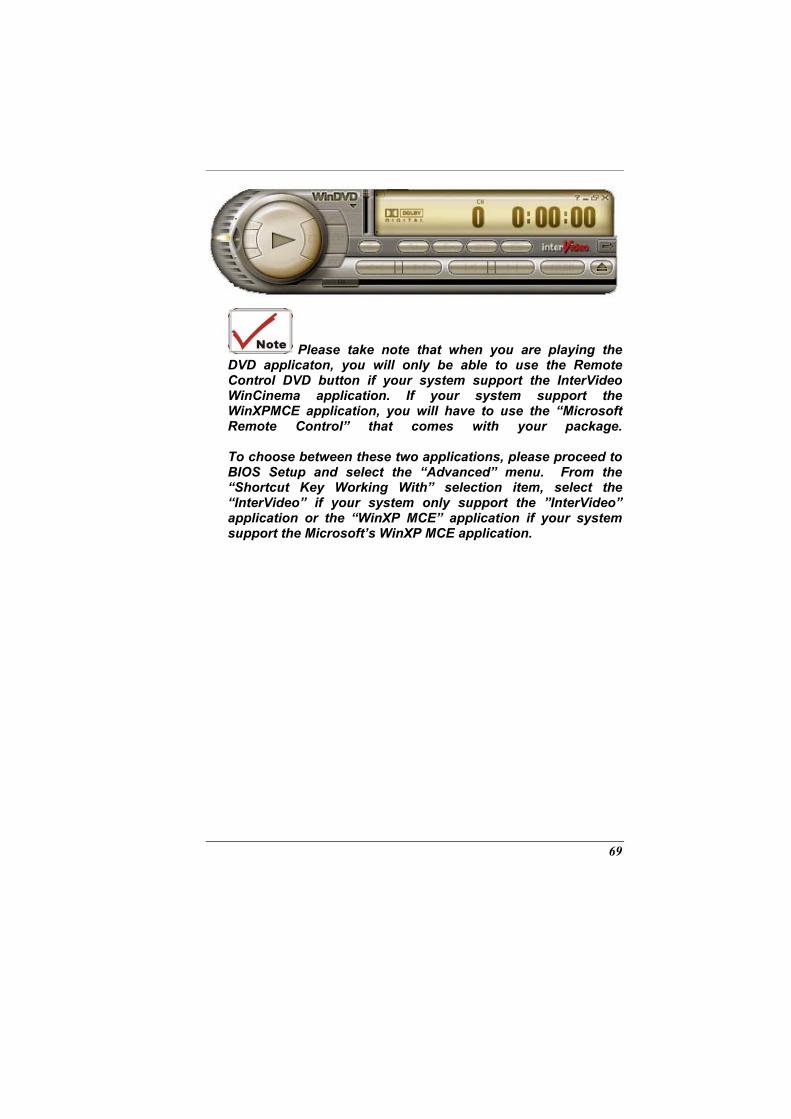
Please take note that when you are playing the DVD applicaton, you will only be able to use the Remote Control DVD button if your system support the InterVideo WinCinema application. If your system support the WinXPMCE application, you will have to use the “Microsoft Remote Control” that comes with your package. To choose between these two applications, please proceed to BIOS Setup and select the “Advanced” menu. From the “Shortcut Key Working With” selection item, select the “InterVideo” if your system only support the ”InterVideo” application or the “WinXP MCE” application if your system support the Microsoft’s WinXP MCE application.
69
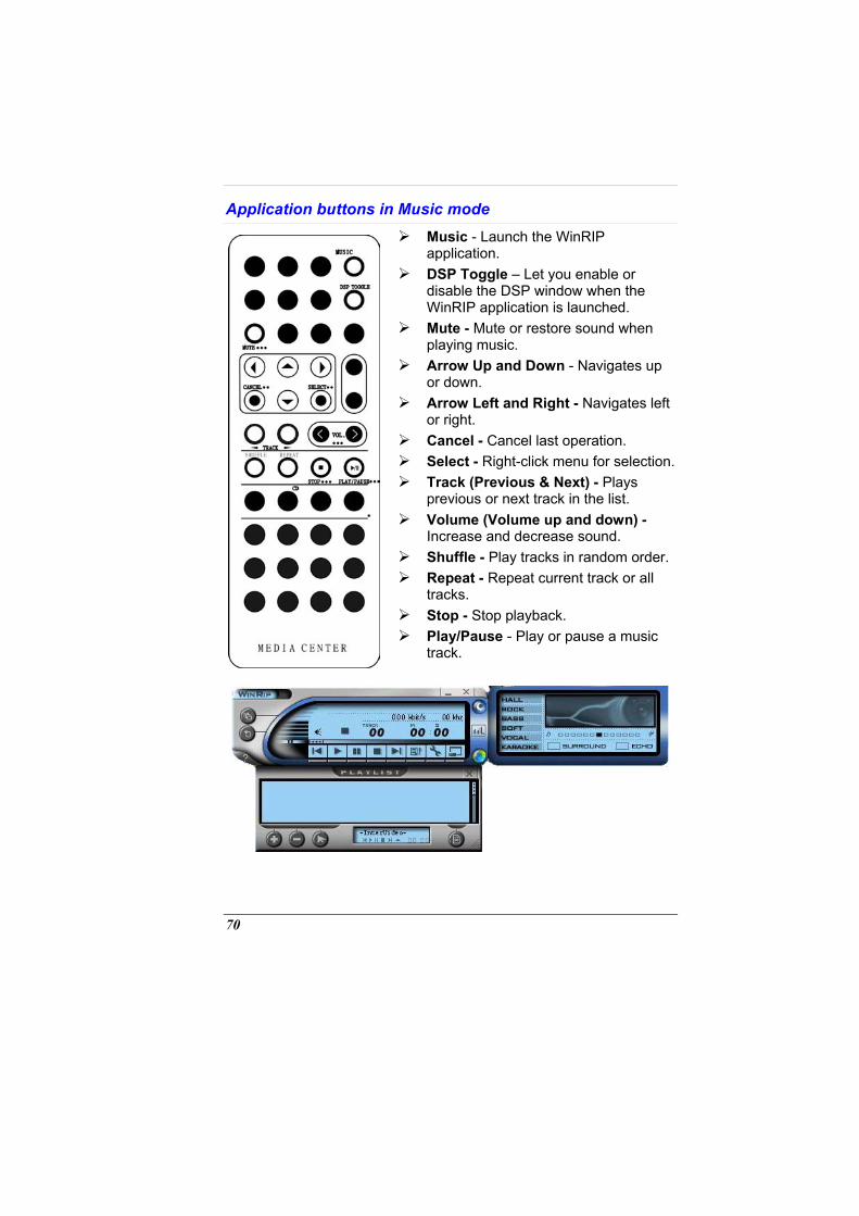
Application buttons in Music mode Music - Launch the WinRIP
application. DSP Toggle – Let you enable or
disable the DSP window when the WinRIP application is launched.
Mute - Mute or restore sound when playing music.
Arrow Up and Down - Navigates up or down.
Arrow Left and Right - Navigates left or right.
Cancel - Cancel last operation. Select - Right-click menu for selection. Track (Previous & Next) - Plays
previous or next track in the list. Volume (Volume up and down) -
Increase and decrease sound. Shuffle - Play tracks in random order. Repeat - Repeat current track or all
tracks. Stop - Stop playback. Play/Pause - Play or pause a music
track.
70
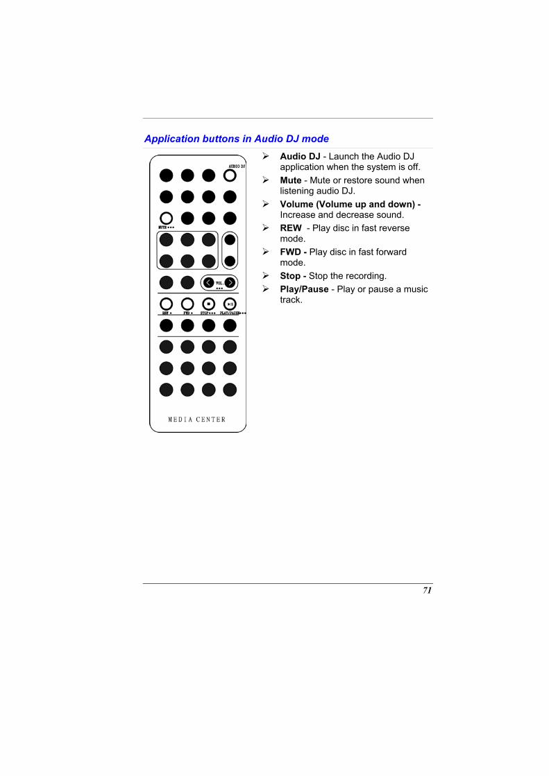
Application buttons in Audio DJ mode
Audio DJ - Launch the Audio DJ application when the system is off.
Mute - Mute or restore sound when listening audio DJ.
Volume (Volume up and down) - Increase and decrease sound.
REW - Play disc in fast reverse mode.
FWD - Play disc in fast forward mode.
Stop - Stop the recording. Play/Pause - Play or pause a music
track.
71

Page intentionally left blank
72
TROUBLESHOOTING
This chapter describes locating and solving problems that you may encounter while using your computer.
Locating a Problem
Problems with your computer can be caused by something as minor as an unplugged power cord – or as major as a damaged hard disk. The information in this chapter is designed to help you find and solve minor problems. If you try all the suggested solutions and you still have a problem, make a list of what steps you have taken to correct the problem and contact your dealer. Successful troubleshooting is the result of careful observation, deductive reasoning, and an organized approach to solving the problem. The problems that you will encounter can be divided into two basic categories: hardware problems and software problems. Hardware problems can be further divided into electrical and mechanical problems. You will know you have a hardware problem if the screen is dark, the computer cannot read the disk drives, or you get an error message during the Power-On Self Test (POST). Software errors can occur at several levels. The ROM BIOS and the operating system can give you a large number of error messages. On top of this, each application software package has its own set of error messages. It is important to determine whether the software error message you are getting is from the application or the operating system. Once you know this, you can look in the respective manual for a solution to the problem.
73
Checking Cables and Connections
Start by performing a careful visual inspection of the exterior of the computer. If no LEDs are illuminated, make sure that your computer and its peripherals are getting power and communicating with each other properly. To check the power cables, and connections: 1.
2.
3.
4.
If you have been using battery power, connect the Notebook to an external power source and make sure that the battery has a charge. If you are using the Notebook with the AC adapter, check the power outlet, the power cord, and any power switches that may affect your computer.
• Check the wall outlet or power strip with an item that you know is functioning properly. A lamp or radio is a convenient item for checking the power. You may also need to check the fuses and breakers in your electric box.
• If the outlet is controlled by a wall switch, make sure that the switch is on.
• If the outlet is controlled by a dimmer switch, use a different outlet.
• If your computer is plugged into a power strip with an On/Off switch, make sure the switch is on.
With the computer’s power switched off, check all cable connections. If the computer is connected to any peripheral devices, look for loose or disconnected cables.
• If the computer is too close to a wall, a cable connection may be loose or the cables may be crimped.
• Do not substitute cables for different devices (other than the manufacturer recommended cables) even if they look exactly alike. The wiring inside the cable may be different.
When you are certain that you have power available and all connections are good, turn the computer on again. If the computer still does not start, you may have a hardware problem.
74
The Power-On Self Test
The Power-On Self Test (POST) runs every time you turn on or reset the Notebook. The POST checks memory, the main system board, the display, the keyboard, the disk drives, and other installed options. A few seconds after you turn on your computer, a copyright message appears on your display screen. A memory test message appears next; as the test continues, memory size increases until all installed memory is tested. Normally, the only test routine visible on the screen will be the memory test. Two classifications of malfunctions can be detected during the POST: • Error messages that indicate a failure with either the hardware, the
software, or the Basic Input/Output System (BIOS). These critical malfunctions prevent the computer from operating at all or could cause incorrect and apparent results. An example of a critical error is microprocessor malfunction.
• Messages that furnish important information on the power-on and boot processes (such as memory status). These non-critical malfunctions are those that cause incorrect results that may not be readily apparent. An example of a non-critical error would be a memory chip failure.
In general, if the POST detects a system board failure (a critical error), the computer halts and generates a series of beeps. If failure is detected in an area other than the system board (such as the display, keyboard, or an adapter card) an error message is displayed on the screen and testing is stopped. It is important to remember that the POST does not test all areas of the computer, only those that allow it to be operational enough to run diagnostic programs. If your system does not successfully complete the POST, but displays a blank screen, emits a series of beeps, or displays an error code, consult your dealer.
General Hardware Problems
A few common hardware problems and suggested solutions are presented in the table below: Problem: The capacity of the battery is between 95 to 99% but can not fully charged.
75
Solution:
Problem:
Solution:
Problem:
Solution:
Problem:
Solution:
Problem:
Solution:
Problem:
Solution:
Problem:
Solution:
Problem:
Solution:
Please discharged to less than 95% of its capacity then recharge the battery.
Failure in the installation of the Audio driver.
Be sure to first remove the current audio device from your system. Please follow the instruction on the installation of audio driver.
The display screen is dark
Make sure that the computer is not in Suspend mode. Check the Brightness controls for the screen. If the controls are turned too far down, the screen will be dark.
An incorrect date and time are displayed.
Correct the date and time using the DOS DATE and TIME commands or the options in the Setup Utility. If the date and time become incorrect after a short time, your CMOS battery may be depleted. Contact your dealer to change the battery.
You hear irregular beeps during operation of the Notebook and the system halts.
The problem is beyond the scope of this manual. Contact technical support.
An unidentified message is displayed.
Reboot the computer and run the BIOS system setup. Confirm the Setup parameters. If the same message is displayed after booting up again, contact technical support for assistance.
The system cannot access the DVD-ROM drive.
Check that a CD is properly inserted in the drive. Make sure that you are using the correct program for that kind of CD. For example, the system cannot read a data CD using an audio program.
You cannot operate the printer.
Check the printer USB cable connection. Ensure that the printer power switch is turned on. Confirm that the printer is on-line.
76
Problem:
Solution:
Problem:
Solution:
Problem:
Solution:
You can’t save data to disk.
Ensure that the disk has been formatted. Consult your operating system manual for information on formatting floppy diskettes.
You cannot use the mouse.
Check the cable connection. Check the mouse with another application to see if there is a software incompatibility problem. If possible, check the mouse with another computer to see if it works. If it doesn’t operate on a different system, the mouse might be broken.
The fan does not stop operating when the system enters the suspend mode.
Before entering the suspend mode, the fan still operates in full speed to lower down the temperature of the system. When the system temperature reduces into normal condition then the fan will gradually slow down into its normal speed.
Contacting Your Dealer
If you still have a problem after reading the preceding sections, the next step is to contact your dealer. Your dealer can determine if the problem is something that requires the computer to be taken to the shop. Before you call your dealer, however, prepare the following information: • How is your computer configured? Your dealer needs to know what
peripheral devices you are using. • What messages, if any, are on the screen? • What software were you running at the time? • What have you done already to try to solve the problem? If you
have overlooked a step, your dealer may be able to solve the problem over the phone.
77

Page intentionally left blank
78
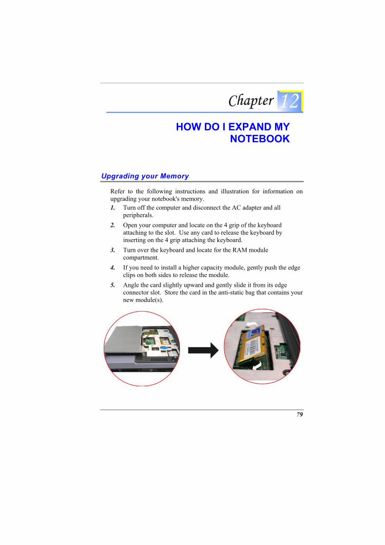
HOW DO I EXPAND MY
NOTEBOOK
Upgrading your Memory
Refer to the following instructions and illustration for information on upgrading your notebook's memory. 1.
2.
3.
4.
5.
Turn off the computer and disconnect the AC adapter and all peripherals. Open your computer and locate on the 4 grip of the keyboard attaching to the slot. Use any card to release the keyboard by inserting on the 4 grip attaching the keyboard. Turn over the keyboard and locate for the RAM module compartment. If you need to install a higher capacity module, gently push the edge clips on both sides to release the module. Angle the card slightly upward and gently slide it from its edge connector slot. Store the card in the anti-static bag that contains your new module(s).
79
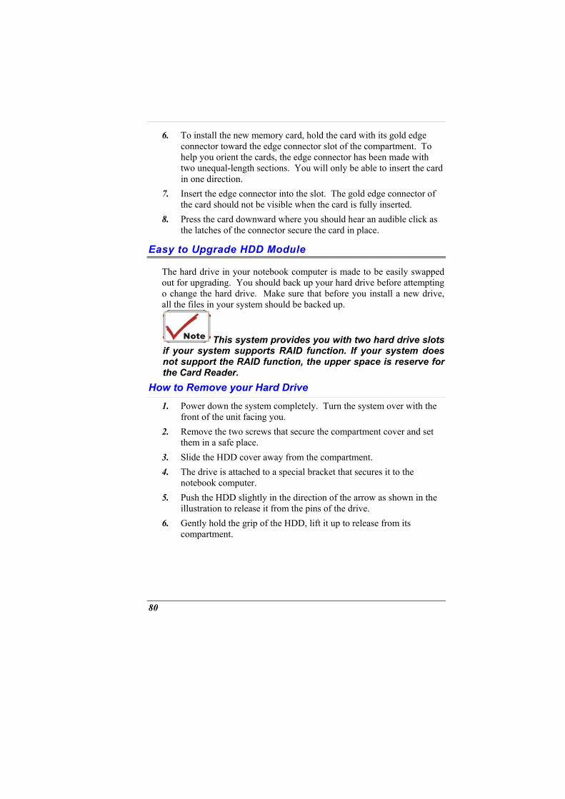
6.
7.
8.
To install the new memory card, hold the card with its gold edge connector toward the edge connector slot of the compartment. To help you orient the cards, the edge connector has been made with two unequal-length sections. You will only be able to insert the card in one direction. Insert the edge connector into the slot. The gold edge connector of the card should not be visible when the card is fully inserted. Press the card downward where you should hear an audible click as the latches of the connector secure the card in place.
Easy to Upgrade HDD Module
The hard drive in your notebook computer is made to be easily swapped out for upgrading. You should back up your hard drive before attempting o change the hard drive. Make sure that before you install a new drive, all the files in your system should be backed up.
This system provides you with two hard drive slots if your system supports RAID function. If your system does not support the RAID function, the upper space is reserve for the Card Reader.
How to Remove your Hard Drive 1.
2.
3. 4.
5.
6.
Power down the system completely. Turn the system over with the front of the unit facing you. Remove the two screws that secure the compartment cover and set them in a safe place. Slide the HDD cover away from the compartment. The drive is attached to a special bracket that secures it to the notebook computer. Push the HDD slightly in the direction of the arrow as shown in the illustration to release it from the pins of the drive. Gently hold the grip of the HDD, lift it up to release from its compartment.
80
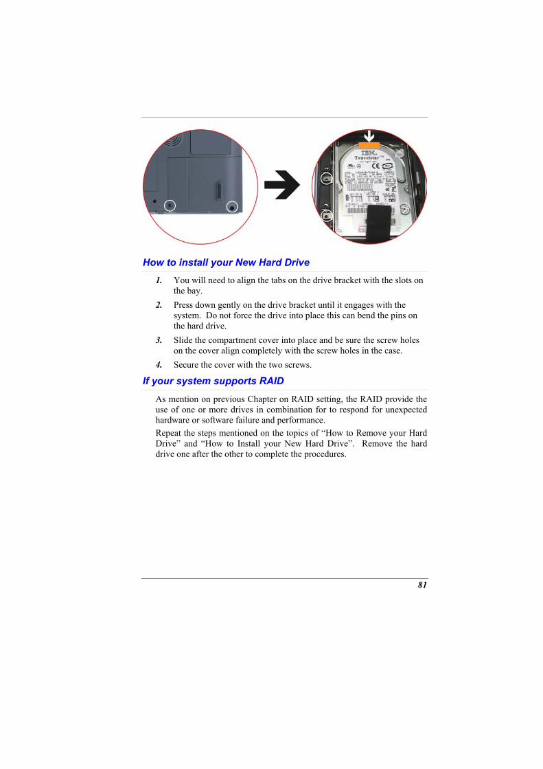
How to install your New Hard Drive 1.
2.
3.
4.
You will need to align the tabs on the drive bracket with the slots on the bay. Press down gently on the drive bracket until it engages with the system. Do not force the drive into place this can bend the pins on the hard drive. Slide the compartment cover into place and be sure the screw holes on the cover align completely with the screw holes in the case. Secure the cover with the two screws.
If your system supports RAID
As mention on previous Chapter on RAID setting, the RAID provide the use of one or more drives in combination for to respond for unexpected hardware or software failure and performance. Repeat the steps mentioned on the topics of “How to Remove your Hard Drive” and “How to Install your New Hard Drive”. Remove the hard drive one after the other to complete the procedures.
81
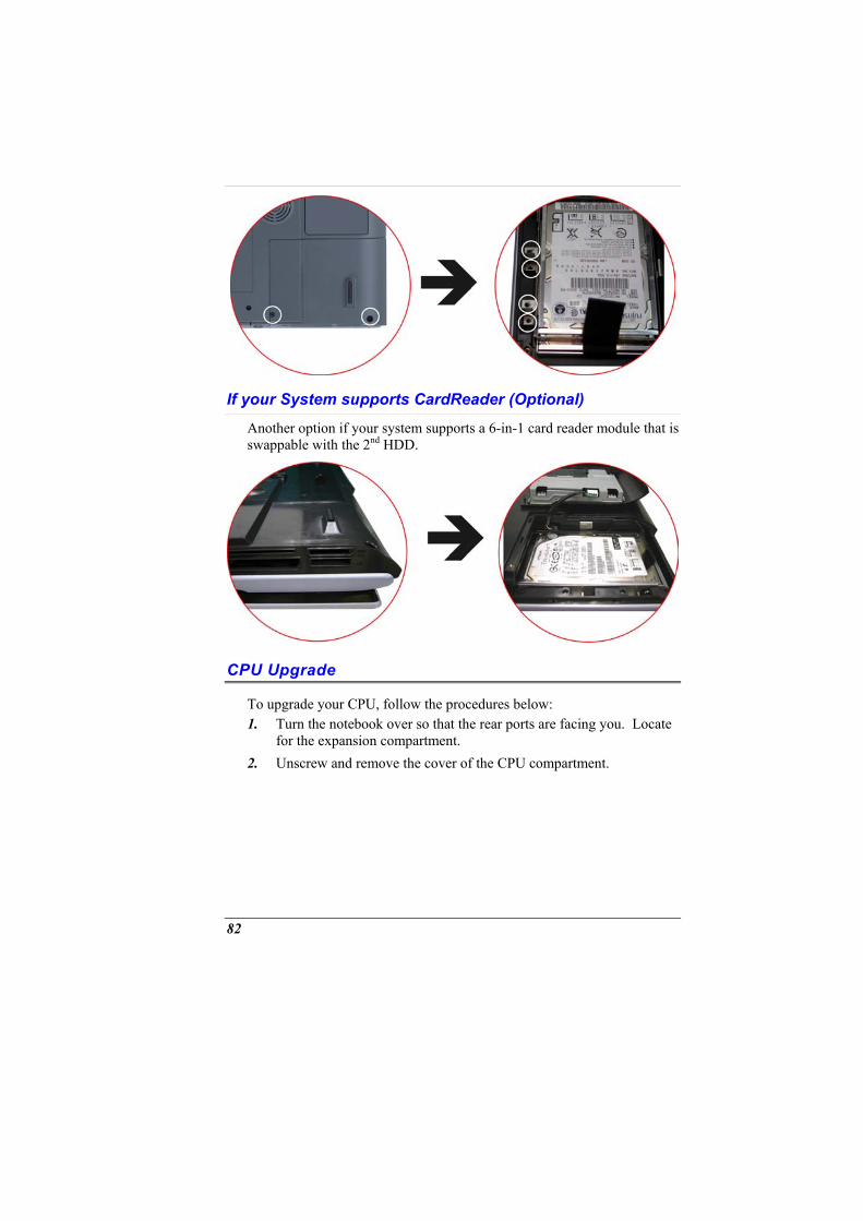
If your System supports CardReader (Optional)
Another option if your system supports a 6-in-1 card reader module that is swappable with the 2nd HDD.
CPU Upgrade
To upgrade your CPU, follow the procedures below: 1.
2.
Turn the notebook over so that the rear ports are facing you. Locate for the expansion compartment. Unscrew and remove the cover of the CPU compartment.
82
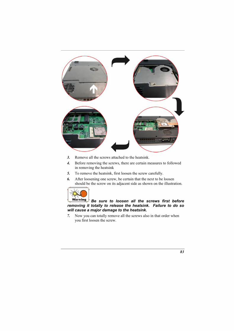
3. 4.
5. 6.
Remove all the screws attached to the heatsink. Before removing the screws, there are certain measures to followed in removing the heatsink To remove the heatsink, first loosen the screw carefully. After loosening one screw, be certain that the next to be loosen should be the screw on its adjacent side as shown on the illustration.
Be sure to loosen all the screws first before removing it totally to release the heatsink. Failure to do so will cause a major damage to the heatsink. 7. Now you can totally remove all the screws also in that order when
you first loosen the screw.
83

Page intentionally left blank
84
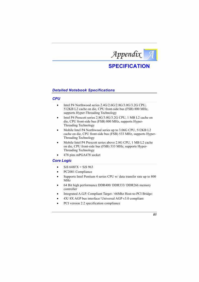
SPECIFICATION
Detailed Notebook Specifications
CPU • Intel P4 Northwood series 2.4G/2.6G/2.8G/3.0G/3.2G CPU,
512KB L2 cache on die, CPU front-side bus (FSB) 800 MHz, supports Hyper-Threading Technology
• Intel P4 Prescott series 2.8G/3.0G/3.2G CPU, 1 MB L2 cache on die, CPU front-side bus (FSB) 800 MHz, supports Hyper-Threading Technology
• Mobile Intel P4 Northwood series up to 3.06G CPU, 512KB L2 cache on die, CPU front-side bus (FSB) 533 MHz, supports Hyper-Threading Technology
• Mobile Intel P4 Prescott series above 2.8G CPU, 1 MB L2 cache on die, CPU front-side bus (FSB) 533 MHz, supports Hyper-Threading Technology
• 478 pins mPGA478 socket
Core Logic • SiS 648FX + SiS 963 • PC2001 Compliance • Supports Intel Pentium 4 series CPU w/ data transfer rate up to 800
MHz • 64 Bit high performance DDR400/ DDR333/ DDR266 memory
controller • Integrated A.G.P. Compliant Target / 66Mhz Host-to-PCI Bridge: • 4X/ 8X AGP bus interface/ Universal AGP v3.0 compliant • PCI version 2.2 specification compliance
85
• USB 1.1/2.0 host controller • Dual IDE Master/ Slave Controller • Integrated Fast Ethernet MAC controller • Integrated Audio controller w/ AC97 interface: AC97 v2.2
compliance • Integrated IEEE 1394a host controller • Advanced Power Management: meets ACPI v1.0b requirement,
meets APM 1.2 requirement • Integrated DMA Controller • Integrated Interrupt Controller • Integrated Keyboard Controller: supports PS/2 Mouse interface • Integrated PCI to LPC bridge: LPC 1.0 Compliance
Memory
Main Memory • 2 expandable memory slot up to 1GB with 512Mb technology • 128/256/512 MB memory module options • Two 200pin DDR SODIMM type memory slots • 2.5V DDR SDRAM module
ROM • 512KB Flash ROM • Boot block protection
Mass Storage
HDD • Supports Disk Array function, RAID 0 or RAID 1 (Factory Option) • Supports Enhanced IDE (PIO mode 4) and bus master (Ultra DMA
33/66/100 mode) • Easily upgradeable 2.5” 9.5mm HDD
Module Bay • Supports DVD-ROM/ Combo Drive/ DVD+/-RW / DVD Dual;
5.25” 12.7mm height • Fast IDE and ATAPI interface DVD-ROM/ Combo Drive/ DVD+/-
86
RW
Disk Array (Factory Option)
Controller • Promise PDC20265R Bus Mastering Ultra DMA PCI—
ATA/ATAPI Controller
Features • Supports RAID 0 or RAID 1 • Single chip ATA/ATAPI controller implementation for easy
integration • Bus mastering design takes full advantage of multi-tasking, multi-
threading operating systems and greatly improves performance • Provides scatter/gather DMA mechanism that complies with
Revision 1.0 of the Programming Interface for Bus Master IDE Controller
• Scatter/Gather mechanism supports both DMA and PIO IDE drives and ATAPI devices. Allows byte-boundary memory region during Bus Master DMA transfers which benefits operating systems or applications, which has odd byte boundary memory transfers
• Dual independent data paths with read ahead and write posting for each channel supported for dual IDE channels to balanced bus loading and optimal performance
• Supports flash memory interface for easy to update of BIOS • Provides PCI Power Management 1.0 capability
Card Reader (Factory Option)
Controller • C-Media CM-120 USB 6-in-1 combo card reader
Features • 6-in-1 card reader with 4 sockets • USB 2.0 full speed • Compliant with USB storage device class specification • Compliant with USB HID device specification v1.0 • Fixed USB full speed mode 12Mbits/s
87
• USB bus power and self power capability. Lower power consumption.
• Internal PLL, only takes 12MHz crystal to provide 48MHz frequency.
Supports Compact Flash card (CF), Microdrive card (MD), Smart Media card (SM), Multi Media card (MMC), Secure Digital card (SD), and Memory Stick card (MS) interfaces
Pointing Devices • Synaptics TouchPad
Keyboard • US/Europe, DOS/V keyboard for Japan, full size keyboard alike
pitch • 300 mm keyboard with key stroke 3.0mm • Twelve function keys and Windows Function key • Internal keyboard works a standard 101/102 desktop keyboard
Audio
Controller • Built-in chipset
Codec • C-media 9761
Features • Built-in 5 high quality stereo speakers, high frequency*2, median
frequency*2 and sub-woofer*1 • Add Jack-sense capability • Full duplex 6 channels DAC/2 channels ADC • Supports S/PDIF output • AC’97 2.3 & PC2001 compliant
Audio DJ • Controller: O2 OZ168 Audio DJ • Ability to play music CD without powering on the system
88
• Ability to play DVD/Music when powering on the system • Operation keys: (Play/Pause, FF, RW, Stop, Volume Up, Volume
Down)
Communication
Gigabit Lan (Factory Option) • Controller: Marvell 8001 Integrated Gigabit Ethernet Controller • Supports PCI 2.2, 32bit, 33/66 MHz • Wake-on-LAN and remote wake-up support
Mini PCI WLAN (Factory Option) • Built-in wireless LAN Antenna • Switch to turn on/off the RF • Three optional WLAN modules: 802.11b or 802.11g or 802.11b +
modem combo card
Modem • Built-in MDC V.90 56K Fax/Modem
TV Tuner Module • Mini PCI Type3B Interface TV tuner with coaxial connector • Philips mini tuner with Philips Video/Audio decoder SAA7135 • Supports NTSC, PAL/SECAM • Adopt software MPEG2 solution by using InterVideo WinDVR
software application. • Supports capture function to record the TV programs into HDD • Multi-function remote control to enjoy TV programs
Remote Control • Allow turn on/off system in a distance (Only in AC mode) • Friendly user interface to enjoy AV function, includes TV, DVD
and Music/Audio DJ • Four modes function keys to enjoy the AV function
TV mode: For watching the TV show and even capture, instant replay or pause a TV program
89
DVD mode: For playing the DVD with high-quality picture and supporting the time stretching
Music mode: For enjoying the music and lets you can record, store and organize your music collection AudioDJ mode: For enjoying the music from Audio DJ without power on the system
I / O Ports
Standard Ports • One S-video TV out port for TV • One DC input port for External AC adapter (2-pin DC jack) • One Type II PCMCIA Card Socket • One video port for external analog VGA monitor (15-pin female D-
connector) • USB 2.0 port x 4 • MIC-in, • Headphone jack w/ adaptor for 5.1 channel SP/DIF support • Audio jack x 3, supports 6 channels surround sound output • RJ-11 jack for Fax/Modem: MDC 56K FAX/Modem • RJ-45 jack for LAN: On board 10/100/1000 Gigabit LAN chip • IEEE 1394a mini-jack • IR Receiver for remote control • Antenna connector (75 ohm) for TV in • Fiber optic transmitting connector • One connector for MCE IR blaster box (optional)
PCMCIA • Controller: ENE CB1410 • Supports 1 PC Card/CardBus slot • Supports 16-bit & CardBus PC Cards, PCI rev. 2.2 and PC Card
Standard Release 7.0 compliant
IEEE 1394a • Controller: SiS963+Realtek 8801B PHY • Data transfer rate: 100/200/400 Mbps
90
Graphic and Video
Controller • ATI Mobility M11-P, 708-pin BGA package
Features • 3D Acceleration Feature: four parallel 3D rendering pipelines/ full
DirectX9 Pixel Shader 2.0 support • Dual Display: Dual independent display (LCD/DVI, DVI/CRT,
LCD/TV, CRT/TV, etc), integrated TV encoder w/ on-chip triple DAC
• Digital Display support: supports flat panel displays via DVI/ fixed resolution from VGA to wide UXGA; integrated LVDS transmitter and TMDS transmitter
• Comprehensive AGP support: AGP3.0 mode (4X and 8X operation), AGP2.0 mode (1.5V signaling only)
• PCI 2.3 compliance (using AGP electrical interface)
Graphic Memory • Discrete 128MB DDR RAM (Flexible graphics memory
configuration: 16MB up to 128MB DDR SGRAM or SDRAM)
Power Management • Full ACPI 1.0b, OnNow; IAPC power management; PCI bus power
management 1.1 and AGP Busy and Stop signals Rev. 1.61 and Solano 2-M
LCD Display • Supports 17” WXGA LCD (1440*900)
Electrical
AC Adapter • External universal type AC adapter, output maximum 150W
Smart Battery • 12 x 2400mAh Lithium-Ion battery pack @ 106whr • User interchangeable
91
• Removable and rechargeable • Charging time for one battery pack: 3.5 hours to full charge when
system off or in suspend • More than 2.0 hours battery lifetime under Ziff-Davis Inc.
BatteryMark 4.01 Test with Intel 478 pin Northwood 2.4GHz CPU and 17” XTFT LCD installed at 25oC
Dimensions • Weight: 4.5 Kg • Size: 397.0 x 285.0 x 39.0/44.0 mm
Options • Mini PCI WLAN 802.11b/802.11g (Built-in wireless LAN antenna)
or 802.11b combo card (modem + WLAN) • 2nd HDD or 6 in 1 Card Reader • Memory Extension Card • Module bay: DVD-ROM/Combo (DVD-ROM+CD-RW) Drive,
DVD+/-RW • Spare Li-Ion Battery Pack
Accessories • User‘s Manual & Driver CD title • AC Adapter • Power Cord • Remote Controller for AV function
Software Specifications
System BIOS • AMI BIOS
VGA BIOS • ATI M11 VGA BIOS
Operating system • Optional Windows XP RTM or above version
Device Drivers and Utilities
92

93
• VGA driver, • Audio driver, • Touch-Pad driver, • Modem driver, • LAN driver, • WLAN driver, • RAID driver, • Card reader driver, • AV function applications