Embed Size (px)
Citation preview

E L KO E P
E L KO E P R u s s i a
KO E P P oKO E P P oP o l a n dE L KOKOKO dP oP o
E L KO E P S l o v a k i aS a
E L KO E P H u n g a r yO
EE L KOE L KO in i aO E P E P RR o m a nE E nO E nLE LLE L
aE L KO E P U k r a i n eU k r aU k r aU k r a
ELKO EP, s.r.o. | Palackého 493 | 769 01 Holešov - Všetuly Email: [email protected], Tel.: +420 573 514 211, GSM: +420 608 371 500, Fax: +420 573 514 227
Czech republic
www.elkoep.com
11/2009 | © Copyright ELKO EP, s.r.o. | I. Issue
E L E C T R O N I C M O D U L A R D E V I C E S
2 0 1 0
E L E C T R O N I C M O D U L A R D E V I C E S
I N T E L L I G E N TE L E C T R O - I N S T A L L A T I O N
W I R E L E S S C O N T R O L L
H O U S E S W I T C H E S A N D S O C K E T S L O G U S 9 0

• Installation is realized very simply without any demolition or cutting in walls. Units (actuators) can be installed directly in a sui-table installation box, in light cover, switchboard and wherever in-stallation allows it.
• Flexible positioning: It is ideal for installations into exi-sting buildings, for reconstructions and for new constructed buildings; With RF Control, you are not dependent on switch po-sitioning e.g. when you move furniture. You can locate the wire-less switch on glass surface, attach it to a beam or only put it on your bedside table, so that, it can be relocated anytime easily.
• Control of lights from terrace or garage opening?Portable control - you will have the keychain always ready!
• For control can be used also OASiS detectors, which react to movement, door or window opening, temperature increasing etc., like this, you can automatically for example turn on light when pas-sing by detector or switch the heating off if window is opened.
• Property protection and security: Flooding detector, tempera-ture detector, smoke or gas-escape detector will give command to the actuator that will close water or gas supply line, start ventilation system etc.
• Allows controlling and adjusting of various lighting scenes, si-mulation of sunrise or sunset. It is also possible to control shutters, blinds, Venetian blinds, gates or latches.
• Transmitters (wireless switch or keychain)do not require exter-nal power supply for their operation (they are powered from batte-ry).
• Installation of receivers (actuators) into installation box, under existing switch, in light cover or on DIN rail in switchboard.
• Elegant style of wall button controllers in glass, wood, metal or granite design.
What does wireless control bring to you?• Remote control of appliances or electric devices• Light dimming, lighting scenes• Control of blinds, Venetian blinds, external and between glass shutters• Control of entrance gates, garage gates• Either manual or automatic control is possible - according to the defined program• Appliances switching without or with dependence on reaction of used detectors • Reaction to gas-escape• Reaction to (undesirable) window or door opening• Response to movement of persons (authorized and unauthorized)
Flat wireless switches for positioning on glass, tiling or furniture.Quick change of positioning when moving.
The LOGUS 90 line is characterized by simplicity, high-quality materials and modern design. This line off ers basic plastic version of frames and a luxury version made of natural materi-als - precious metals, hardened glass, wood or granite. Besides wireless controllers, are also produced in this design standard house switches and sockets.
Select your style . . . *
CONTROL
OF SHUT-
TERS AND
BLINDS
LIGHT SWIT-
CHING ON
FROM ANY
PLACE
MONITORING
OF CRITICAL
TEMPERATU-
RES
CONTROL OF
LIGHTING
SCENES
... in the place where the possibilitie
WIRELESS
ELECTROINSTALLATIONS
868MHz
* For control with wall switch buttons, you can connect existing controllers to the system (using universal input modules) or use fl at wireless pushbuttons in LOGUS90 design.
RF ControlW I R E L E S S
C O N T R O L Interact communication
2

Compatible
RF Control system off ers wireless control of electric appliances and devices in dependence on time, light dimming, control of blinds, shutters, garage doors, entrance gates etc.
OASiS is an ingenious system of wireless detectors that protects your house against burglars and damages which can be caused by fi re, gas-escape, fl ooding with water etc.
What does the compatibility of RF Control and OASiS system mean?
Compatibility means mutual communication between transmitters and receivers of wireless elements of both systems. RF Control & OASiS compatible allows comfortable control of frequently required functions from basic switching of appliances (e.g. ventilator, air conditioning sys-tem) or lighting switching and dimming. These operations takes place:
• through wireless switches or keychain or automatically - in dependence on time • and newly thanks to OASiS detectors also in dependence on movement, door or window opening, smoke dete-ction, gas-escape, glass shattering or light intensity.
Thanks to communication with OASiS, RF actuator can activate also an interior siren or send command into GSM gate - DAViD and inform you through SMS or by calling to your mobile phone.
More options, more functions...• Simple programming by system functions setting.• Easy change of preset functions.• Multifunctional switches and dimmers offer selection from up to seven preset programs or functions.
RF Control and OASiS wireless systems
can communicate with each other!
RF Control Oasis
REMOTE
CONTROL OF
APPLIANCES
BY MOBILE
PHONE
LIGHT ACTIVA-
TION IN CASE
OF PASSING
THROUGH
PROTECTION
AGAINST FIRE,
FLOODING
ETC.
SUNRISE AND
SUNSET
SIMULATION
ARBORE PETRA CRYSTAL METAL BASEAQUARELLA
&
NEWNEW
es of classic electro-installation end?
CONTROL OF YOUR
HOUSEHOLD
Coverage up
to 200m
W I R E L E S S
S E C U R I T Y S Y S T E Mwireless components
3www.rfcontrol.cz
Control wireles pentru
RECEPTOARE WIRELESS
Modul universal de receptie
Switching actuators (basic / 6 functions)
Switching actuators (basic / 6 functions)
Number of function
Switching power
Number of contacts
Rated current
Power supply
Shutters actuators (230 V / 12-24 V)
Dimming actuator with controller
Dimming actuators (basic / 7 programs)
2 6
4000VA/AC1, 384W/DC
1x switching (AgSnO2)
16 A / AC1
230 V AC
6
4000VA/AC1, 384W/DC
1x switching over (AgSnO2)
16 A / AC1
230 V AC
2 2
2000VA/AC1 perm. 1A
2x switching (AgSnO2) X
8 A / AC1
230 V AC 12-24V DC
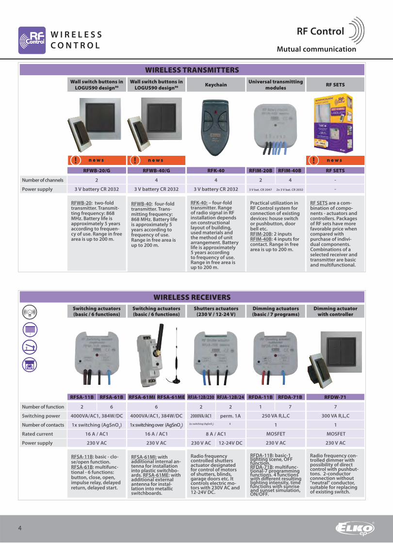
RFSA-11B: basic - clo-se/open function. RFSA-61B: multifunc-tional - 6 functions: button, close, open, impulse relay, delayed return, delayed start.
RFSA-61MI: with additional internal an-tenna for installation into plastic switchbo-ards. RFSA-61ME: with additional external antenna for instal-lation into metallic switchboards.
Radio frequency controlled shutters actuator designated for control of motors of shutters, blinds, garage doors etc. It controls electric mo-tors with 230V AC and 12-24V DC.
7
300 VA R,L,C
1
MOSFET
230 V AC
Radio frequency con-trolled dimmer with possibility of direct control with pushbut-tons. 2-conductor connection without "neutral" conductor, suitable for replacing of existing switch.
RFSA-11B RFSA-61B RFSA-61MI RFSA-61ME RFJA-12B/230 RFJA-12B/24 RFDW-71RFDA-11B RFDA-71B
1 7
250 VA R,L,C
1
MOSFET
230 V AC
RFDA-11B: basic-1 lighting scene, OFF function.RFDA-71B: multifunc-tional-7 programming functions. 4 functions with diff erent resulting lighting intensity, time functions with sunrise and sunset simulation, ON/OFF.
Wall switch buttons inLOGUS90 design90 Keychain Universal transmitting
modules RF SETS
n e w s
RFK-40 RF SETS
n e w s
RFWB-40/G RFIM-20B RFIM-40B
WIRELESS TRANSMITTERS
Number of channels
Power supply
2
3 V battery CR 2032
4
3 V battery CR 2032
4
3 V battery CR 2032
-
-
2 4
RFWB-20: two-fold transmitter. Transmit-ting frequency: 868 MHz. Battery life is approximately 5 years according to frequen-cy of use. Range in free area is up to 200 m.
RFK-40: – four-fold transmitter. Range of radio signal in RF installation depends on constructional layout of building, used materials and the method of unit arrangement. Battery life is approximately 5 years according to frequency of use. Range in free area is up to 200 m.
Practical utilization in RF Control system for connection of existing devices: house switch or pushbutton, door bell etc.RFIM-20B: 2 inputsRFIM-40B: 4 inputs for contact. Range in free area is up to 200 m.
RF SETS are a com-bination of compo-nents - actuators and controllers. Packages of RF sets have more favorable price when compared with purchase of indivi-dual components. Combinations of a selected receiver and transmitter are basic and multifunctional.
RFWB-40: four-fold transmitter. Trans-mitting frequency: 868 MHz. Battery life is approximately 5 years according to frequency of use. Range in free area is up to 200 m.
WIRELESS RECEIVERS
Wall switch buttons inLOGUS90 design90
n e w s
RFWB-20/G
4
RF ControlW I R E L E S S
C O N T R O L Mutual communication
4
3 V bat. CR 2047 2x 3 V bat. CR 2032

Motion detector Optical smoke detector Door opening detector "Invisible" window detector
JA-81M JA-82M JA-80P JA-80S
868 MHz
1 x lithium battery AA 3,6V
Typically up to 300 m in case of direct visibility
110x60x55mm 88x46x27 mm
868 MHz
1 x lithium battery AA 3,6V
Typically up to 300 m in case of direct visibility
diameter 126, height 65 mm
868 MHz
lithium battery typeLS(T)14500 (3,6V AA)
approximately 300 m direct visibility
110 x 31 x 26 mm
868 MHz
2 x lithium battery type CR2354 (3 V)
approximately 200 m direct visibility
192 x 25 x 9 mm
Infra-passive JA-80P
motion detector monitors
space and signals presen-
ce of persons. JA-85P is
a miniature wireless PIR
motion detector suitable
for small rooms or car
interiors.
Optical smoke detector
reacts on presence
of the visible combustion
products and temperatu-
re increasing in the room
caused by fi re.
Product is designated
for detection of window
(door) opening. "Invisible"
magnetic sensor is to be
installed inside of plastic
or wooden window
frames and is totally
discrete.
Miniature JA-85B
detector is designated
for detection of breaking
of glass panels that form
cladding of the protected
space.
Interior siren Wireless roomthermostat
JA-80L TP-83
Operatingfrequency
Power supply
Communication range
Dimensions
868 MHz
230 V, 50 Hz, 1,5 W
100 m on direct sight
90 x 65 x 45 mm
Range+6 až +40°C
1 Alkaline battery AA 1,5 V
up to 100 m on direct sight
65 x 88 x 20 mm
Wireless siren powered
from mains outlet is used
as a powerful interior
siren. Close to the entran-
ce into the building can
operate as an indicator
of arrival and departure
delay.
TP-83 - controls heating
according to weekly
program (TP-82-version
without weekly program-
ming). TP-83IR - reads
fl oor temperature and
controls heating accor-
ding to weekly program.
WIRELESS PIR DETECTORS
THERMOSTATS
Miniature glass brea-king detector
JA-85B
The product is designated for doors, windows opening detection etc. The detector is also designated for detection of manipulation with ex-ternal shutters equipped with ratchet sensor of shutters movement.
Operatingfrequency
Power supply
Communication range
Dimensions
868 MHz
lithium battery type AA 3,6 V
100 m direct visibility
88 x 46 x 22 mm
5
JA-85P
TP-83IR
SIRENS OTHER COMPONENTS OF SYSTEM OASiS
W I R E L E S S
S E C U R I T Y S Y S T E Mwireless components
www.rf-control.com
SECURITY CENTRALS IN THE SYSTEM - additional modules
UNIVERSAL RECEIVERS
▪ radio module, wire input module
▪ communicators GSM / GPRS, LAN / TEL ,
telephone
▪ for communication with centrals,
wireless thermostats
KEYBOARDS AND READERS▪ keyboard with reader RFID + keyboard zone
▪ anti-vandal keyboard + RFID card reader
▪ access cards, chips..
PIR DETECTORS▪ motion detector with camera
▪ two-zone detector
▪ external detector
▪ combined detector
▪ fl ammable gas detector
SIRENS▪ interior sirens
▪ external sirens
PROGRAMMABLE THERMOSTATS
▪ with daily or weekly program, wireless
thermostats
CONTROLLERS ▪ keychain, universal controllers

Number of contactsinput
Number of contactsoutput
Rated current
Power supply
GD-04 „David“GD-04 „David“
news
GD-04 „David“
GSM CONTROLLER AND COMMUNICATOR GD-04 "DAVID“
E L E K T R O N I C
M O D U L A R D E V I C E S
GD-04D
4
2
5A
11÷13 V DC
GD-04A GD-04P GD-04R
6
Reporting to a mobile phone
- four input terminals (A through D) can report closing and opening
through SMS.
David's functions can be set by:
Internet form Computer with GD Link program SMS message
Mobile phone controlled
RELAYS
- two output contacts (X and
Y) which can be used as:
- Switch controlled with SMSs.
- Relay controlled by ringing.
- Report by mobile phone.
GD-04A backup
module, thanks to
which David
obtains the ability
to operate for
approximately 12
to 24 hours.
DTMF module GD-04D,
thanks which is possible
to control David's output
relay by calling and inser-
ting a numerical code to
phone pad.
GD-04P interconnecting
cable with which is
possible to connect
David with computer’s
USB port for setting with
GDLink program.
DG-04R radio module
allows activating inputs
(A through D) by using
of wireless pushbuttons
and detectors OASiS.
□ HYGROSTATS
□ USS MODULES
□ TWILIGHT SWITCHES
□ MEMORY RELAYS
□ AUXILIARY RELAYS
□ DIMMERS
□ MODULAR THERMOSTATS
□ ROOM AND OUTDOOR THERMOSTATS
□ TIME RELAYS
□ MULTIFUNCTION TIME RELAYS
□ DIGITAL TIME RELAYS
□ SUPER MULTIFUNCTION RELAYS
□ SOCKET RELAYS
□ STAIRCASE AUTOMATS
□ MONITORING VOLTAGE RELAYS
□ MONITORING CURRENT RELAYS
□ LEVEL SWITCHES
□ BELL POWER SUPPLIES
□ TRANSFORMERS
Electronic modular devices
Electro-installation improves more and more at present. Emphasis is laid on safety, comfort, time saving and last but not the least, on energy sa-ving.
For that reason, we submit you a complete off er of electronic modular de-vices that will help you to meet such requirements and bring new possi-bilities in the fi eld of control, monitoring or security of your house, fl at, offi ce or control of industrial processes.
Electronic devices supplied by our company complement the standard equipment of switchboards and so they are produced in modular type of construction with mounting on DIN rail. Our off er includes also devices designated for mounting into installation (instrument) box that allows application into existing installation.
Off er covers the products for use in house installations and also for indu-strial applications, while some devices intermesh mutually.
We have more than 15 years of experiences in the given fi eld and we have utilized these experiences consistently within the framework of our development and transferred consequently in the latest models of our products. Thanks to our R&D center, we can react fl exibly to atypical re-quirements of our customers, whether by product function adjustment or development of new product.
All products comply not only with the requirements of standards but they are also certifi ed by independent testing laboratories throughout the world.

►
zvlhčuje, odvlhčuje
0 - 90%
1x spínací (AgSnO2)
12A / AC1
AC 230 V / 50..60 Hz
hygro-termostat
50 - 90%
1x spínací (AgSnO2)
16A/AC1,10A/24V DC
24 - 230 V AC/DC
Funkce
Relativní vlhkost
Počet kontaktů
Jmenovitý proud
Power supply
Počet funkcí
Zpoždění
Počet kontaktů
Jmenovitý proud
Power supply
-
0 - 2 min
1x přepínací (AgSnO2)
16 A / AC1
230 V AC/DC 12 - 240V
-
0 - 10 min
1x přepínací (AgSnO2)
8 A / AC1
AC 230 V /50-60 Hz
-
0/1min /2 min
1x spínací (AgSnO2)
12 A / AC1
AC 230 V /50-60 Hz
1
-
1x přepínací (AgSnO2)
16 A / AC1
AC 230 V, AC/DC 12-240 V
2
-
2x přepínací (AgSnO2)
16 A / AC1
Ac 230 V, AC/DC 12-240 V
zvlhčuje, odvlhčuje
0 - 90%
1x spínací (AgSnO2)
12A / AC1
AC 230 V / 50..60 Hz
hygro-termostat
50 - 90%
1x spínací (AgSnO2)
16A/AC1,10A/24V DC
24 - 230 V AC/DC
Funkce
Relativní vlhkost
Počet kontaktů
Jmenovitý proud
Power supply
n e w s
E L E K T R O N I C
M O D U L A R D E V I C E S
n e w s
7
Snap it by your-self
HYGROSTATS USS MODULES
Hygro-thermostat Hygrostat Thermo sensors for thermostats
Controlling and signaling modulesUSS-ZM, USS-00 až USS-15
RHT-1 RHV-1 TC, TZ, PT USS-ZM - basic module
Hygro-thermostat for temperature monitoring and control- range 0..+60°C and relative humidity - range50..90%. Sensor is part of device - designated for measuring in switchbo-
ard.
Simple hygrostat for
monitoring and control
of relative humidity.
Outdoor version
with IP65 protection,
box for wall mounting,
removable lid without
screws.
Cable lengths:
TC-0: sensor length 10 cm)
TC-3: 3m, TC-6: 6m,
TC-12:12m
TZ-0: 11 cm, TZ-3: 3m,
TZ-6: 6m, TZ-12: 12m
PT100-3: 3m, PT100-6: 6m
PT100-12: 12m
USS-01-Switch USS-02 - Switch over
USS-03 - Switch with intermediate position
USS-04 - Switch + pushbutton with intermediate position
USS-05 - Switching pushbutton with intermediate position
USS-06 - Pushbutton closing/opening
USS-07-09 - Switch with glow tube
USS-07-09 - Switch with glow tube
USS-10-15 - LED signal (red, green, blue)
Designated for switching, control and signaling of
auxiliary and power circuits. USS- "Do-it-yourself" =
various types of switching and signaling units can be
"snapped" in the basic module.
Units are supplied separately, individual confi gurations
are assembled by the user.
TC: Types of thermo sen-
sors for range 0..+70°C.
TZ: Types of thermo sen-
sors for range -40..+125°C.
PT100: Types of thermo
sensors for range
-30..+200°C.
MEMORY RELAYSDIMMING ACTUATORSTwilight switch with
external sensorTwilight switch with
time switchTwilight light switch with
in-built sensor Memory stepping relay Memory stepping relay
SOU-1 SOU-2 MR-41 MR-42SOU-3
It can be used for control
of lighting on basis of
ambient light intensity.
Adjustable lighting level
in two ranges: 1-100 LX
and 100-5000Lx. Time
delay 0-2 min.
Designated for control of
lighting on basis of am-
bient light intensity and
real time (combination
of SOU-1 and SHT-1 time
switch in one). Adjustable
lighting intensity level
1-50000Lx.
It can be used for control
of devices on basis of am-
bient light intensity level.
Outdoor confi guration
with IP65 protection. In-
built light intensity sensor.
2 devices in one - twilight
switch, light switch.
Memory (impulse) switches controlled with pushbuttons
for lighting control from more places.
Relays remember their condition even after power supply
outage recover, so that relay is always turned off during
power supply outage and after power supply recovers,
relay returns in the same condition as before power supply
outage.
-
-
1x switching over (AgSnO2)
16 A / AC1
AC 230 V, AC/DC 12-240 V
Function
Relative humidity
Number of contacts
Rated current
Power supply
it humidifies, dehumidifies
0 - 90%
1x switching (AgSnO2)
12A / AC1
AC 230 V / 50..60 Hz
hygro-termostat
50 - 90%
1x switching (AgSnO2)
16A/AC1,10A/24V DC
24 - 230 V AC/DC
Number of functions
Delay
Number of contacts
Rated current
Power supply
external
0 - 2 min
1x switching (AgSnO2)
16 A / AC1
230 V, AC/DC 12 - 240V
external
0 - 10 min
1x switching over (AgSnO2)
8 A / AC1
AC 230 V /50-60 Hz
internal
0/1min /2 min
1x switching (AgSnO2)
12 A / AC1
AC 230 V /50-60 Hz
-
-
2x switching over (AgSnO2)
16 A / AC1
AC 230 V, AC/DC 12-240 V
www.elkoep.com

750
A1 - A2 A1 - A2
AC 230 V AC/DC12-240V
A1 - A3 -
AC/DC 24 V -
3x switching over (AgNi)
8A / AC1
A1 - A2 A1 - A2
AC/DC 24 V AC 230 V
- -
- -
3x switching over (AgSnO2)
16A/AC1
A1 - A2
AC (6,12,24,120,230 V)
-
DC (6,12,24,48,110 V)
3x switching over (AgSnO2)
16 A
They are used as enhancement or extension for exi-
sting device contact numbers. Possibility of LED color
selection for output status indication: red, green, yellow,
blue or white LED. In-built diode for suppression of
unwelcome peaks at relay opening and RC interference
suppression component.
VS316/24 or VS316/230
allows switching of diff -
erent phases or 3-phase
voltage.
It is used to switch a higher output (load) than the capa-
city of switching element = amplifi er.
Auxiliary control of lighting, signaling, relay interlocks,
boilers, HDO, direct heaters, mechanical indication
incorporated in standard, LED indication, cadmium-free
gold-plated contact, locking lever.
Controlled dimmer Controlled dimmer Controlled dimmer Expandable power module for DIM-6 Controlled dimmer
DIM-6 DIM6-3M-P
Numbers of contacts
Rated current
Power supply
Load
1 x triak 2xMOSFET
2A
AC 230V / 50 HZ
R -10- 500 VA R - 500 VA
L -10-250 VA L - 500 VA
- C - 500 VA
2 x MOSFET
2A
AC 230 V /50-60Hz
LED bulbs
Dimmable saving units
-
n e w s
4 x MOSFET
10 A
AC 230 V /50 Hz
R - 2000 VA
L - 2000 VA
C - 2000 VA
2 x MOSFET
5 A
AC 230 V /50 Hz
R - 1000 VA
L - 1000 VA
C - 1000 VA
1xtriac 2xMOSFET
-
230 V AC
R -10-300 VA R - 500 VA
L -10-150 VA L - 500 VA
- C - 500 VA
Designated for dimming
of bulbs and halogen
lamps with wound
transformer. Possibility of
parallel control buttons
arrangement .
Designated for dimming of dimmable LED bulbs with power supply 230 V and dimmable saving fl uorescent lamps. Slight setting of light intensity by using pushbutton.
Dimmer can be controlled by several methods: pushbutton, external potentiometer, analog signal 0-10V. Possibility of modular extension up to 10kVA.
Expandable power mo-dule for DIM-6 cannot be operated separately.
Pushbutton controlled dimmers designated for mounting into installati-on box. They are used for control of lamp brightne-ss, possibility of control from more places.
Power terminals
Power supply
Power terminals
Power supply
Number of contacts
Rated current
VS116K VS116U VS308K VS308U VS316/24 VS316/230 782
A1 - A2 A1 - A2
AC 230 V AC/DC 12-240 V
A1 - A3 -
AC/DC 24 V -
1x switching (AgSnO2)
16A/AC1
A1 - A2
AC (6,12,24,120,230 V)
-
DC (6,12,24,48,110 V)
4x switching over (AgSnO2)
8A
DIM-5 DIM-15 SMR-S SMR-U
DIMMERS
DIM-14
n e w s
8
AUXILIARY RELAYSAuxiliary
relayAuxiliary
relayAuxiliary
relayAuxiliary relay
into socketAuxiliary relay
into socket
E L E K T R O N I C
M O D U L A R D E V I C E S

Simple thermostats Simple thermostats Double thermostat Multifunction thermostat
TER-4 TER-9 TER-3 A, B, C, D, G, H TER-3 E, F
Simple thermostat for
temperature monitoring
and control within range
-30+70°C. Possibility of
"heating"/"cooling" func-
tion setting (realized with
DIP switch). Adjustable
hysteresis (sensitivity).
Simple thermostat for
temperature monito-
ring and control within
range 0+60°C. TER-3E:
- selection from external
temperature sensors.
TER-3F: - sensor is a part
of device.
Double thermostat for
temperature monitoring
and control within wide
range -4.+110°C. 2 tem-
perature outputs for NTC
sensor. 2 independent
switching output contacts
16A.
Digital thermostat with 6 functions and in-built time switch. 2 thermo-stats in 1, 2 tempera-ture inputs, 2 outputs. Functions: 2 independent thermostats, dependent thermostat, diff erential thermostat.
It monitors motor winding temperature. PTC sensor in-built in motor winding is used as a sensing element. Error condition RESET:a) with pushbutton on front panel b) with exter-nal contact.
Analog room thermostats
Digital room thermostats
Two-level thermostatIP65
One-level thermostatIP65
External thermostatIP65
TEV-1 TEV-2 TEV-3Thermo DT (DTR, DTF, DTC) TEV-4
n e w s
+5..+35°C -20+20°C
internal
1 x switching over (AgNi)
16 A
230 V AC
-30+60°C
internal
1 x switching
12 A
230 V AC
ATR - room thermostat with temperature range +5..+40°C. ATF-fl oor thermostat with temperature range +5..+50°C.ATC-combined thermo-stat with room and fl oor sensor.
DTR - room thermostat.
DTF - fl oor thermostat.
DTC – combined ther-
mostat with room and
fl oor sensors. DTF, DTC -
external sensor.
Two-level thermostat
with "WINDOW" function;
i.e. output is closed if is
measured temperature
between set temperature
values (adjustable within
range -20..+20°C).
Single-level thermo-
stat with possibility of
temperature control in
adjustable range. it is
used for heating control
(or cooling control) in
more demanding areas.
Simple thermostat for
monitoring and control
of temperature in outdo-
or spaces and demanding
environments. Two functi-
ons that can be set with a
link: heating and cooling.
Motor winding tempe-rature monitoring
TER-7
Monitored ranges
Sensor / Type
Number of contacts
Rated current
Power supply
-30..+10, 0..40, 30..70 , 0..60,15+45°C
external, NTC, except for TER-3G(PT100)
1x switching (AgSnO2)
16A/AC1 10A/24 V DC
AC/DC 24-240V
0..+60°C
external, NTC in-built
1x switching (AgSnO2)
16A/AC1 10A/24 V DC
AC/DC 24 - 240 V
-40+110°C
external, NTC
2x sw. over (AgSnO2)
16A/AC1
AC 230, AC/DC 24 V
-40.. +110°C
external, NTC
2 x switching over
8A/AC1
AC 230, AC/DC 24 V
-
external, PTC
2x sw. over (AgNi)
8A/AC1
AC 230, AC/DC 24 V
Temperature/Hysteresis
Sensor / Type
Number of contacts
Rated current
Power supply
Thermo AT (ATR, ATF, ATC)
ATR ATF,ATC
+5..+40°C +5..+50°C
internal external / internal
1 x switch
16A/250 V 4000VA při AC1
AC 230 V
DTR DTF,DTC
+5..+50°C
internal DTF-ext./DTC-int.and ext.
1 x switch
16A/250 V 4000VA při AC1
AC 230 V
2 x -20 +20°C
internal
1 x switching over (AgNi)
16 A
230 V AC
MODULAR THERMOSTATS
ROOM AND EXTERNAL THERMOSTATS
E L E K T R O N I C
M O D U L A R D E V I C E S
9www.elkoep.com

Single-function time relay
Delayed return without power supply voltage Two-grade delay unit Delayed ON
star / delta
SJR-2CRM-82TO
E L E K T R O N I C
M O D U L A R D E V I C E S
Single-function and
single-time relay. Suitable
for applications with
beforehand known
requirements for function
and time. ZR - delayed
start ZN - delayed return
BL - cycler 1:1.
Relay is timing without power supply voltage and is switched off after set period. Two time functions selectable by using a rotary switch: a-delayed return after power supply is switched off : e - delayed start.
Serves for sequent swit-
ching of high power.
2 time functions: 2x dela-
yed start. Adjustable time
from 0.1 s to 10 days.
Designated for delayed
star/ delta motor start.
Time t1 (star) – adjustable
time from 0.1 s to 100
days. Time t2 (delay)
between /Δ - time range
from 0.1 s to 1 s.
Time relay - cycler with
independently adjustable
output closing and
opening time. 2 time
functions: 1) cycler starting
with impulse.
2) cycler starting with gap.
Multifunction time relay
Multifunction time relay
Multifunctional time relay with contactless output
Time relay with external potentiometer
Asymmetric cyclerwith external potenc.
CRM-9S CRM-91HECRM-61 CRM-2HE
Use for electric applian-ces, control of lighting, heating, motors, pumps etc.; ...6 functions. Comfort and transparent setting of functions and time ranges is carried out with function rotary switches.
Multifunctional time relay for universal use in automa-
tion, management and control or in house installations.
Thanks to its abundant equipment (10 functions, 10 time
ranges, universal power supply, 16A or 3x8A contact), it
covers all requirements. Comfort and transparent setting
of functions and time ranges is carried out with function
rotary switches. CRM-9S: absolutely noiseless switching.
Time relay with possibility of time control with external
control component - potentiometer.
CRM-91HE: multifunction time relay. Time adjustable
from 0.1 s to 10 days.
CRM-2HE: asymmetric cycler.
Asymmetric cycler
CRM-81J CRM-83J CRM-2T CRM-2T 24-480 CRM-2H
Number of functions
Time range
Number of contacts
Rated current
Power supply
3 functions
0.1 - 10 h (6 ranges)
1x sw.over 3x sw.over
16 A/AC1 8A
AC 230 V, AC/DC (12-240V)
2 functions
0.1 - 10 min. (4 ranges)
2x switching over
8 A / AC1
AC/DC (12-240V)
2 functions
0.1 - 10 days (8 ranges)
2x switching over
16A / AC1
AC 230 V, AC/DC (12-240V)
1 function
0.1 s - 100 days (10 ranges)
2x sw.over 2x sw.over
16A/AC1 3A/AC1
AC 230 V, AC/DC 24-480 V
2 functions
0.1 - 10 days (10 ranges)
1x switching over
16A/AC1
AC 230 V, AC/DC (12-24V)
CRM-91H CRM-93H
Number of functions
Time range
Number of contacts
Rated current
Power supply
6 functions
0.1 s - 10 h
1x switching over
8A/AC1
AC 24-240 V, DC 24 V
10 functions
0.1 - 10 days
1x sw.over 3x sw.over
16A/AC1 8A/AC1
AC 230 V, AC/DC (12-240V)
10 functions
0.1 - 10 days
1x switching over
triac - 0,7 A
AC (12-240V)
10 functions
0.1 - 10 days
1x switching over
16A/AC1
AC/DC (12-240V)
2 functions
0.1 - 100 days
1x switching over
16A/AC1
AC/DC (12-240V)
TIME RELAYS
MULTIFUNCTION TIME RELAYS
10

Time switch with weekly program
Time switch with annual program
Programmable digital relay
Super-multifunction relay
E L E K T R O N I C
M O D U L A R D E V I C E S
Serves for control of various appliances in dependence on real time, in daily, weekly and annual mode. Automa-tic transfer between summer and winter time.Sealable transparent front panel cover. 100 memory places, back-lighted LCD display.Reserve real time backup - up to 3 years.
PDR-2A: - 20 memory places for most frequently used times PDR-2B: - 2 time relays in one device.
Relay designated for mounting into installation box, under pushbutton or switch into existing electro-instal-lation. SMR-T: 3-wire connection, it operates without "NEUTRAL" connection, output power: 10-160 VA, it cannot be used for fl uorescent and saving lamps. SMR-H: 4-wire connection, output power: 0-200 VA, it cannot be used for fl uorescent and saving lamps. SMR-B: 4-wire connection, it allows switching of fl uorescent and saving lamps
Time relay into socket Asymetric cycler into socket Staircase automat Programmable
staircase automatStaircase automat
with dimming
CRM-4 CRM-42PRM-91H
Number of functions
Time range
Number of contacts
Rated current
Power supply
Equivalents of modular types of relays, constructed
for standardized round 11-pin or 8-pin sockets. Socket
design allows easy replacement, substitution of older
types of relays (pin compatible) or simple replacement
of auxiliary relay by timer. PLUG-IN version, installation
into socket.
Serves for delayed
lighting turning off in
staircase, corridor or
entrance. It is controlled
with pushbutton or
several pushbuttons from
more places (parallel
connected).
Intelligent staircase auto-mat for same application as CRM-4, however, with extended possibility of control in "PROG" mode, it is possible to select delayed switching off time with the number of depressions of control pushbutton.
Regulation: - start duration -1-40s- fi nish duration- 1-40s- time for which light should have the set brightness-0s-20min- brightness to which ligh-ting should be activated - 10-100%
Super-multifunction relay
Number of function
Time range
Number of contacts
Rated current
Power supply
SHT-1 SHT-1/2 SHT-3 SHT-2/3 PDR-2A PDR-2B SMR-B
PRM-92H PRM-2H DIM-2
SMR-T SMR-H
1-channel 2-channel
min. step 1s
1x sw.over 2x sw.over
16A/AC1 16A/AC1
AC 230 V, AC/DC (12-240V)
1-channel 2-channel
min. step 1s
1x sw.over 2x sw.over
16A/AC1 16A/AC1
AC 230 V, AC/DC (12-240V)
16 functions 10 functions
0.01 s - 100 h
2x sw.over 2x sw.over
16A/AC1 16A/AC1
AC 230 V, AC/DC (12-240V)
10 functions
0.1 s - 10 days
1x triac 1x triac
-
AC 230 V
10 functions
0.1 s -10 days
1x switching
16 A
AC 230 V
10 functions
0.1-10 days
1x sw.over 2x sw.over
16A/AC1 8A/AC1
AC/DC (12-240V)
2 functions
0.1-10 days
2x switching over
8A/AC1
AC/DC (12-240V)
3 functions
0.5 -10 min
1x switching over
16A/AC1
AC 230 V
3 functions
0.5 -10 min
1x switching over
16A/AC1
AC 230 V
2 functions
0 s - 20 min.
1 x triac
2 A
AC 230 V
SOCKET RELAYS
DIGITAL TIME RELAY SUPER MULTIFUNTION RELAY
STAIRCASE AUTOMATS
11www.elkoep.com

Monitoring voltage relay, 1 phase, AC
Monitoring voltage relay, 1 phase, AC
Monitoring voltage relay, 1 phase, AC
Monitoring voltage relay, 1 phase, AC/DC
HRN-35
E L E K T R O N I C
M O D U L A R D E V I C E S
Serves for monitoring of power supply voltage for appliance sensitive with respect to power supply tolerances, device protection against under-voltage / overvoltage. It monitors undervoltage and overvoltage level separately. Adjustable delay 0-10 s.
Serves for monitoring of power supply voltage for appliance sensitive with respect to power supply tolerances, device prote-ction against undervol-tage / overvoltage. It has independent output relay for each voltage level.
Serves for monitoring of power supply voltage for appliance sensitive with respect to power supply tolerances, device protection against under-voltage / overvoltage. It monitors undervoltage and overvoltage level separately. Adjustable delay 0-10 s.
Serves for monitoring of power supply voltage for appliance sensitive with respect to power supply tolerances, device prote-ction against undervolta-ge / overvoltage. With its range, it is predestined for monitoring of battery circuits.
Functions: HRN-41: “HYSTERESIS“. HRN-42: “WINDOW“. “MEMORY“-function- for return from error into normal status, it is necessary to press “RESET“ pushbutton. Galvanically separated power supply.
Relay for sequence and phase outage monitoring
Voltage relay for overvoltage / undervoltage monitoring
Voltage relay for overvoltage / undervoltage monitoring
Relay for sequence and phase outage monitoring
Relay for complete monito-ring of 3-phase networks
HRN-55: Supplied from
all phases, i.e. relay func-
tion is retained even one
phase outage.
HRN-55N: L1-N supplying,
i.e. the relay monitors
also neutral wire brea-
king.
Serves for monitoring of voltage in switchboard, protection of devices and equipment. Possibility of setting of top and bottom voltage limits at which the output relay contact opens. Umax 105-125% Un. Umin 75-95% Un.
Serves for monitoring of voltage, sequence and phase outage in swit-chboard, protection of devices and equipment. It is possible to set the top and bottom voltage limits at which the output relay contact opens. Delay of 0.1-10 s.
Relay monitors sequence and outage of phases in circuits:3x120V3x208V3x240V3x400V3x480V3x575V
Relay monitors and con-
trols in 3-phase networks:
- voltage in two levels
(overvoltage and under
voltage)
- phase asymmetry
- phase sequence
- phase outage
Monitoring voltage relay, 1 phase, AC/DC
HRN-33 HRN-63 HRN-41 HRN-42
HRN-57 HRN-57N
HRN-37 HRN-67 HRN-34 HRN-64
Number of contacts
Rated current
Circuit monitoring
Current monitoring (MAX)
Power supply
1x switching over (AgNi)
16 A
1 phases
40 - 276 V
AC 48 - 276 V
1x sw.over for each level (AgNi)
16 A
1 phases
40 - 276 V
AC 48 - 276 V
1x switching over (AgNi)
16 A
1 phases
24 - 150 V
AC 48 - 276 V / AC 24 - 150 V
1x switching over (AgNi)
16 A
1 phases
6 - 30 V 18 - 30 V
DC 6 - 30 V
2x switching over (AgNi)
16 A
1 phases
10 - 50 V, 32 - 160 V, 100 - 500 V
AC 230 V, AC 400 V - AC/DC 24 V
HRN-55 HRN-55N HRN-54 HRN-54N HRN-56, 1 M HRN-56, 3 M HRN-43 HRN-43N
Number of contacts
Rated current
Circuits secure
Current monitoring (MAX)
Power supply
1x sw. over (AgNi)
8 A
3 phases
- -
from monitored
1x sw. oveer (AgNi)
8 A
3 phases
105 - 125 % Un
from monitored
1x sw. over (AgNi)
8 A
3 phases
-
from monitored
1x sw. over (AgNi)
8 A
3 phases
-
from monitored
2x sw. over (AgNi)
16 A
3 phases
3x400V/240-480V 3x400/230V/138-276V
AC 230 V, AC 400 V, 24 V AC/DC
MONITORING VOLTAGE RELAYS - 1 phases
MONITORING VOLTAGE RELAYS - 3 phases
12
V
V

Monitoring current relay, (0.1 - 16 A)
Monitoring current relay, (.. do 20 A)
Monitoring current relay, AC/DC Current transformers
E L E K T R O N I C
M O D U L A R D E V I C E S
PRI-51 monitoring relay is
used to monitor current level
in single-phase AC circuits.
5 ranges : AC 0.1-1A, AC
0.2-2A, AC 0.5-5A, AC 0.8-8A,
AC 1.6-16A
PRI-32 monitoring relay is used to monitor current level in single-phase AC circuits. The product inclu-des also current trans-former; if a conductor is put in it, the transformer detects the size of passing current.
The relay is designated
for monitoring of DC and
AC single-phase currents
in 3 ranges.
Designated as a com
plement to monitoring
current relays of PRI line,
i.e. in order to increase
max.monitored current.
Primary current: 50, 100,
150, 200. 250, 300, 400,
600 A.
Relay monitors phase off -set between current and voltage in 3-phase or also 1-phase networks - it evaluates cos-φ. The relay is predestined for motor overloading/relief monitoring.
Level switch Level switch Level complete unit Multi-grade level switch Level sensors
HRH-4
Level switch with single-status, two-status monitoring. 2 indepen-dent level switches with single-status monitoring. It is possible to select the following functions with DIP switch: replenishing, pumping out, tank level monitoring.
Relay is designated for monitoring of condu-ctive liquids level with possibility of function selection : replenishing or pumping out. The following confi gurations can be set: single-level or two-level switch.
It is a complete unit consisting of HRH-5 level relay and VS425 contactor. Selection of replenishing or pumping out function. Set has IP55 protection.
Device monitors 5 levels by using six sensors (one sensor is common). Transparent indication of level high with six LEDs on device’s panel.
Accessories for level switches:SHR-1-M brass sensorSHR-1-N stainless steel sensorSHR-2 stainless steel sensorin PVC housing.
Relays for monitoring of COS power factor
PRI-41 PRI-42 COS-1
HRH-5 SHR
SR PRI-32 PRI-51 window hysteresis
Number of contacts
Rated current
Circuit monitoring
Current monitoring (MAX)
Power supply
1x sw. over (AgNi)
8 A
1 phases
0,1 - 16 A 0,5-25A
AC 24-240 V, DC 24 V AC 230 V
1x sw. over (AgNi)
8 A
1 phases
1-20 A
AC 24-240 V, DC 24 V
1x sw. over (AgNi)
16 A
1 phases
4-16 A, 1.25 - 5A, 0.4 - 1.6 A
AC 230, AC/DC 24 V
-
-
1 phases
0 - 5 A
-
2x sw. over (AgNi)
16 A
3 phases
cos-φ 0,1 - 0,99
AC 230 V, 400 V , DC 24 V
HRH-1 SHR 2 SHR 3HRH-61M 1N
Number of functions
Number of contacts
Rated current
Sensitivity
Power supply
4
2x sw. over (AgNi)
16A
5 - 100 kΩ
AC 110 V, 230 V, 400 V
2
1x sw. over (AgNi)
8A
5 - 100 kΩ
AC/DC 24-240 V
2
4x switching (AgNi)
25A
5 - 100 kΩ
AC 230 V, AC 24 V
2
1x sw. over (AgNi)
10A
5 - 100 kΩ
DC 12-240 V, AC 230 V
MONITORING CURRENT RELAYS
LEVEL SWITCHES
SHR-probe for guarding
fl ooding.
SHR-2-is used to detect
levels as in wells, boreholes,
tanks
SHR-3-for use in harsh and
industrial environments.
13
A
PRI-52
www.elkoep.com

Transformatoare de putere seria ZTR (8 VA)
ZTR-8-8 ZTR-8-12 ZNP-10-12
AC 8 V AC 12 V
8 VA
2
-
AC 230 V / 50 Hz
AC 4 V
4V 5VA-8V 10VA-12V 15VA
2
-
AC 230V / 50 Hz
DC12V nestab. DC24V nestab.
10VA
3
-
AC 230 V /50-60 Hz
DC 24 V non-stab.
11 VA
3
-
AC 230 V /50-60 Hz
ZTR-15-12
TRANSFORMATORE PENTRU SONERII SURSE DE PUTERE
Pentru uz general – cum
ar fi sursă pentru sonerii
sau uşi cu blocaj electric.
Protecţie impotriva
scurtcircuitului, terminale
duble de ieşire.
ACDC
E L E C T R O N I C
M O D U L A R D E V I C E S
Power supplies of ZNP series (11 VA)
PS-10-12 PS-10-24 PS-30-12 PS-30-24 PS-100-12 PS-100-24 DR-60-12 DR-60-24PS-30-R
Power supplies of PS series (10 W)
Power supplies of PS series (30 W)
Power supplies of PS series (100 W)
Power supplies of DR series (60 W)
PS-10: switched stabilized power supplies with fi xed output voltage, 1-module confi guration.
PS-30: switched stabilized power supplies, 3-module confi guration.
PS-100: switched stabilized power supplies with fi xed output voltage, 6-module confi guration.
Output current is limited with an electronic fuse; power supply switches off in case of exceeding maximum current and
switches on again after a short time delay. Thermal protection - power supply switches off at thermal overloading and
it switches on again after cooling down.
Power supplies of PS series (30 W)
Output voltage
Max. load
Number of modules
Output voltage tolerances
Power supply
12 V DC 24 V DC
0.84 A/10 W 0.42 A/10 W
1
+/-2%
AC 230 V / 50..60 Hz
12 V DC 24 V DC
2.5 A /30 W 1.25 A/30 W
3
+/-2%
AC 230 V / 50..60 Hz
12 V DC 24 V DC
8.4 A/100 W 4.2 A/100 W
6
+/-2%
AC 230 V / 50..60 Hz
Switched stabilized power
supply. Input voltage
(Uprim) in wide range
100-240 V AC. Electronic
protection against short
circuit, overloading and
overvoltage.
12 V DC 24 V DC
4.5 A/54 W 2.5 A/60 W
4,5
+/-2%
88-264 V AC/47-63 Hz /124-370 V DC
12-24 V DC
2.5-1.2A /30W
3
+/-3%
AC 230 V / 50..60 Hz
ZTR-8-8 ZTR-8-12 ZNP-10-12 ZNP-10-24 ZSR-30
AC 8 V AC 12 V
8 VA
2
-
AC 230 V / 50 Hz
AC 4 V, 8 V, 12 V
4 V 5 VA-8 V 10 VA-12 V 15 VA
2
-
AC 230 V / 50Hz
DC 12 V non-stab.
11VA
3
-
AC 230 V /50-60 Hz
DC 5-24 V stab. / DC 24 V non-stab.
10 VA
3
+/- 5%
AC 230 V /50-60 Hz
Output voltage
Max. load
Number of modules
Output voltage tolerances
Power supply
n e w s n e w s
POWER SUPPLIES
BELL TRANFORMERS POWER SUPPLIES
14
ACDC
ACDC
Bell transformers of ZTR series (8 VA)
Bell transformers of ZTR series (8 VA)
ZTR-15-12
Designated for general
use - e.g. for door bell,
door lock supplying.
Universal power supply
with alternating output
voltage.
Designated for general
use - e.g. for door bell,
door lock supplying.
Universal power supply
with alternating output
voltage.
Power supply(10 VA)
Power supplies of ZNP series (11 VA)
Power supply with fi xed output voltage. Protecti-on against short circuit and overloading with a melting fuse.Both AC and DC output voltage: 12 V or 24 V / 11 VA, non-stabilized.
Power supply with fi xed output voltage. Protecti-on against short circuit and overloading with a melting fuse.Both AC and DC output voltage: 12 V or 24 V / 11 VA, non-stabilized.
Controllable power
supply. Supplying of
various devices and
appliances with safe
voltage and full galva-
nic separation from the
mains.

INSTALLATION CONTACTORSInstallation contactors
1-modulInstallation contactors
1-modulInstallation contactors
3-modulMiniature installation
contactor
It is used to switch electric circuits, in particular resistance loads and three-phase asynchronous motors. IP 20 protection - guards providing IP 40
protection of all contactor terminals are available upon request. Installation on DIN rail or on panel.
Installation contactors4,5-modul
Number of poles
Load
Confi guration of contacts
Coil power supply
1
20 A
10, 01
AC/DC 24 V, 48 V, 110 V, 230 V
2
20 A
20, 11, 02
AC/DC 24 V, 48 V, 110V, 230 V
4
25 A
40, 31, 22, 04
AC/DC 24 V, 48 V, 110 V, 230 V
4
20 A
40, 31
AC 24 V, 48 V, 110 V, 230 V
4
40 A 63 A
40, 31, 22, 04
40, 31, 22
AC/DC 24 V, 48 V, 110 V, 230 V
VS120 VS220 VS425 VS420VS440
INSTALLATION CONTACTORS
Installation contactor with manual control
Number of poles
Load
Confi guration of contacts
Coil power supply
2
20 A
20, 11, 02
AC 12 V, 24 V, 42 V, 48V, 110 V, 127 V, 230 V
4
25 A
40, 31, 22, 04
AC 12 V, 24 V, 42 V, 48V, 110 V, 127 V, 230V
VSM220 VSM425
I N S T A L A T I O N
D E V I C E S
15
VS463
They are a special version of installation contactors
providing not only basic functions but also manual
control. They are used to switch accumulation ap-
pliances for heating and service hot water heating.
Optical indicator of on - off status. VSK-11 and VSK-
20 auxiliary contacts can be connected to VSM220
and VSM425 contactors.
INSTALLATION CONTACTORS
AUTO: standard function
of contactor as installa-
tion contactor without
manual control
1: by shifting the switch
from AUTO into 1
position, switching on
contacts are closed and
switching off contacts
are open. This status
continues until the
consequent impulse on
contactor coil.
0: contacts are discon-
nected continuously
(switching on contact)
or they are connected
continuously (switching
off contact) regardless of
voltage. Optical indica-
tor of on - off status.
www.elkoep.cz

16
I N S T A L L A T I O N
D E V I C E S
INSTALLATION CONTACTORSCircuit breakers for rated current. 0.5 - 63A MCB10
Circuit breakers for rated current. 0.5 - 63A MCB10
Accessories for MCB10 - auxiliary switch
Circuit breakers for rated current 80 - 125 A ETIMAT10
Circuit breakers for rated current 80 - 125 A ETIMAT10
Rated voltage
Rated current
Rated frequency
Short-circuit resistance.
230/400V AC, max. 60 V DC
0,5 - 63 A
50/60 Hz
0,5 - 40 A: 10 kA, 15 kA50 - 63 A 6 kA, 10 kA
230/400V AC, max. 60 V DC
0,5 - 63 A
50/60 Hz
0,5 - 40 A: 10 kA, 15 kA50 - 63 A 6 kA, 10 kA
-
6 A (230 V AC), 1 A (110 V DC)
-
1 kA with protection fuse 20 A
230/400 V AC, 60 V DC
80, 100 a 125 A
50/60 Hz
15, 20 kA
230/400 V AC, 60 V DC
80, 100 and 125 A
50/60 Hz
15, 20 kA
MCB10 - 1p. MCB10-2.p ETIMAT10 - 3p.ETIMAT10 - 1p.
Interconnecting rails for circuit breakers,
fuse disconnectors and other devices
Rated voltage
Rated current
Rated frequency
Short-circuit resistance
-
-
-
-
~230 V AC
16 A, 25 A, 40 A, 63 A, 80 A, 100 A
0.03 A, 0.1A, 0.3 A, 0.5 A
10 kA
Interconnecting rails RCB-2
CIRCUIT BREAKERS
Circuit breakers RCB-2 Circuit breakers RCB-4 Combined current protectors RMCB
Accessories for RCB - auxiliary switch
RCB-4 RMCB PS RCB
230/400 V AC
16 A, 25 A, 40 A, 63 A, 80 A, 100 A
0.03 A, 0.1A, 0.3 A, 0.5 A
10 kA
PS MCB
Designated for house, com-mercial and industrial electric distribution systems up to 63 A 230/400 V AC. Designated for protection of cables and wires against overloading and short-circuit. Identifi cation of contacts: ON/OFF designation on switch.
Switching off characteristic.C: In= 80,100 A 20 kAIn= 125 A 15 kAD: In = 80 A 20 kAIn = 100 A 15 kAIt complies with principal requirements for switches. Possibility of auxiliary switch mounting.
CURRENT PROTECTORS
230 V AC
6 - 40 A
50 Hz
10 kA
-
1 A (110 V DC), AC 12
-
1 kA with a protective fuse 20 A
RMCB is a current protector
combining properties of a
miniature circuit breaker and
a current protector that is
functionally independent of
mains voltage.
Designated for house, com-mercial and industrial electric distribution systems up to 63 A 230/400 V AC. Designated for protection of cables and wires against overloading and short-circuit. Identifi cation of contacts: ON/OFF designation on switch.
PS MCB is an auxiliary switch
used for remote signaling
of miniature MCB-10 circuit
breaker to which they are
mounted. You can install PS
MCB even additionally.
Switching off characteristic.C: In= 80,100 A 20 kAIn= 125 A 15 kAD: In = 80 A 20 kAIn = 100 A 15 kAIt complies with principal requirements for switches. Possibility of auxiliary switch mounting.
RCB-2 current protectors are used as a protection of alive part of the circuit against indirect contact and also as a protection against residual voltage on grounded parts that can appear in case of errors in electro-installation.
Type A - sensitive with respect to alternating and pulsation direct current Type AC - sensitive with respect to alternating residual current Type S – designated for sele-ctive arrangement of current protectors and for limitation of the number of undesirable switching off operations.
PS RCB additional switch is
used for remote signaling of
status of contacts (closed/
open) of RCB and for electric
circuit control.
PS RCB switch is to be
mounted on RCB current
protectors.
Interconnecting rails for circuit breakers, fuse disconnectors and other devices. These accessories simplify installation of circuit breakers considerable and will make interconnectivity of individual rows of devices in switchboard easier. This leads to increase of productivity of work and making installation of our devices easier.

17www.logus90.com
H O U S E S W I T C H E S
A N D S O C K E T S
For interactive simulator for selection of design including selection of color and wall structure, please see www.logus90.com
21011: Single-pole switch arrangement 1
21101: Double alternating switch
21111: Socket
MEC21 mechanisms are made of special alloy of non-flammable plastics that prevent in destruction or damage of device body thanks to their strength and elasticity. The plastic design of the mechanism simultaneously ensures safe insu-lation from conductive parts of installation. Installation frame is a fixed part of the system. The complete product is compact and light and allows easy and quick tool-free installation. The depth of the instrument is only 20 mm which allows in-stallation into instrument box. Possibility of mounting by using screws or spacers. Double terminals on each pole allow multiple interconnection without additional terminals.
Characterization of MEC21 mechanisms
For complete overview of designs please see the LOGUS90 Overview Catalogue. For ordering codes and technical information please see the LOGUS90 Technical Catalogue.
LOGUS90 - DESIGN LINES
BASE - plast AQUARELLA - metalic ARBORE - woodMETALLO - metalCRYSTAL - glass PETRA - žula
1 to 5 frameTBR = whiteTMR = ivory
1 to 5 frameTGE = iceTPE = pearlTIS = greyTAL = aluminium(plastic with metalic spray)
1 to 4 frameTCG = glass / iceTCP = glass / pearlTCP = glass / greyTCA = glass / alumi-nium
1 to 5 frameTIA= inox / aluminiumTUS = aluminium / greyTQS = nickel / greyTOP = gold / pearlTRS = chromium / greyTTP = titanium / pearl
1 to 5 frameTFP = beech / pearlTJP = cherry / pearlTNA = walnut / aluminiumTMS = mahogany / grey
1 to 5 frameTGG = granite / iceTGP = granite / pearlTGS = granite / greyTGA granite / alumi-nium
Central shutters controller Two-pole switch Movement detector Socket Card switch Rotary switch
Control devices
▪ switches ▪ switches with lock▪ over-switches▪ rotary switches▪ dimming switches
▪ pushbuttons▪ switch, pulling switch▪ shutters controllers▪ shutters controllers with IR sensor▪ digital time switch
▪ motion detectors▪ card switch▪ Jazz Light Sound system- audio system units
▪ standard▪ Schuko, EURO-USA▪ ceramic▪ data sockets Cat 5, Cat 6 ▪ radio, TV, satellite, data▪ telephone sockets
Sockets
LOGUS90 - MEC21 DEVICES - you can select from 150 types!

18 www.logus90.com
▪ Frame and cover can be "snapped" thanks to "smart clips" on the front side of device, which allows simple variation and adaption to interior changes.
MEC21 device Frame Cover Complete device
EXAMPLE OF ORDERING
LOGUS90 - FRAMES AND COVERS OF DEVICES
H O U S E S W I T C H E S
A N D S O C K E T S
BR = white
MF = ivory
GE = ice
PE = pearl
AL = aluminium
IS = grey
▪ All design lines are in 1 frame up to 4 frame version.▪ BASE and AQUARELLA lines are in 1 frame up to 5 frame version.
▪ Horizontal or vertical frame positioning thanks symmetrical shape.
+ + =
ordering no.: 21. . .21011= Single-pole switch 21111= socket
ordering no.: 909. . Txx90910 TBR= 1 frame, plastic/white90930 TCS= 3 frame, glass/grey
ordering no.: 90. . Txx90601 TBR= cover simple, white90652 TAL= socket cover, aluminium.
21011, 90910 TBR90601 TBRdevice, frame, cover
SIMULATOR : INTERACTIVE DESIGN SELECTION
In the website www.logus90.com, you can find overview of all LOGUS90 design lines; you can also set any combinations of sha-des and colors using simulator here.

W I R E L E S S
C O N T R O L L I N G
RF Touch
• it detects temperature in a given area (terrace, cellar, balcony) and sends infor-mation in the central unit• battery powered
RFTI-10B – Wireless
temperature sensor
• it allows setting various ligh-ting scenes just like you wish • possibility of sunrise and sun-set simulation within time inter-val 2s - 30min
RFDA-71B
Dimming actuator
• it controls your shutters, blinds, Vene-tian blinds and also garage door
RFJA-11B – Shutter acuator
-
• in LOGUS90 elegant design• it detects temperature in an area with a sensor, however, it is possible to connect an external sensor for installation e.g. into the fl oor• switching can be controlled also manually
RFSTI-11G – Wireless swit-
ching temperature sensor
• sit detects temperature and, simul-taneously, it switches heating or air conditioning system• all communication is wireless
RFSTI-11B – Wireless swit-
ching temperature sensor
Switch Thermo Input
• Serves for control of lights, appli-ances and electric devices.
RFSA-11B – Switching actor
You can control by single touch: • heating in your house even in each room separately - you will save energy in this way • switching of electric appliances • creating of lighting scenes (when watching a fi lm, reading a book) • control of shutters, blinds and gates• you control all this by using of wireless method – no cabling• in LOGUS90 elegant designWith the central unit, you have everything under control from one place.You control your house with a mere touch
• temperature correction for a give room• temperature setting with timing function• activation of "Night mode" – temperature adaption to the value required by you• thanks to fl at design, the device can be positioned (even stuck) anywhere on wall
RFTC-10B
Digital thermoregulator
Illustrative photo
Complete house at single touch...The RF Touch system is a member of your household that will surprise you not only with appearance but also with its functions and simple touch control. It brings you savings in heating, light dimming and electric appliances switching. It is fully committed to fulfi ll your ideas as to simplicity of control and selection of positioning. And that all thanks to mutual wireless communication between system units.
Teplota
Spínání
Rolety
Stmívání
Vytápění
Teplota
pSpínání
yRolety
Stmívání
Vytápění
Teplota
Spínání
Rolety
Stmívání
Vytápění
Teplota
pSpínání
yRolety
Stmívání
Vytápění
19www.rf-control.com

I N T E L L I G E N T
E L E C T R O - I N S T A L L A T I O N
■ INELS electro-installation intelligent system controls operation of your house from control of heating and air conditioning system, control of lighting, shutters and other appliances up to house security and protection of your property.
■ It is able to recognize changes of system func-tions when compared with the required status and to inform you about such changes through mobile phone, PDA or Internet.
■ INELS is designed so that it could satisfy small electro-installations and to manage also control of large systems requiring automation and complexness.
■ It means that INELS can be used for family hou-ses, flats, administrative and commercial facilities, for large buildings or complexes of buildings and for industrial sphere.
■ It differs from a standard installation by the fact that all sensors (switches, pushbuttons, detectors) and actuators (relays, dimmers etc.) are connected in parallel through 2-wire bus and only then, these components are configured.
Remote access
through Internet, PDA or SMS messages.
Control of heating and air conditioning
in each room (heating circuit) separately, control of temperature in depen-dence upon weather conditions.
Control of outdoor shutters
blinds or even garage doors, sliding latches...
Security system
monitoring of movement, penetration into building by burglary. Preventi-on of fi re through detection of escape of gas or smoke.
Presence simulation
automatic control of shutters in dependence on time, random lighting switching.
Control of lighting
lighting scenes in dependence on ambient light intensity, movement or on time.
Central control
of selected lights and appliances, switching off particular socket circuit by single control button press
Control of appliances
appliances in dependence on time / temperature / lighting intensity or on other preset modes, you can control any appliances that form a part of INELS system.
Wall switch buttons WSB
Wireless controllers for control
with RF signal
Room thermo-regulator
regulator for heating or air conditioning control
SOPHY unit for control with voice
and remote controller
Universal remote (IR) controller
Safety keyboard
of integrated secured system
„Touch screen panel" touch display for complete control of the whole system using INELS Design & Manager (IDM) program.
Program for complex overview and control of all appliances, which are part of electro-installation.IDM allows assignment and setting of various functions to individual controllers. It allows pre-setting heating mode or control of appliances in dependence on real time, temperature or other events.
SYSTEM FUNCTION INTERIOR CONTROL
INELS DESIGNER & MANAGER
Your house likes you...
20
INTELLIGENT AND COMFORTINELS ELECTRO-INSTALLATION

I N T E L L I G E N T
E L E K C T R O - I N S T A L L A T I O N
Benefi ts for the CUSTOMER when compared with conventional installation:
Comfort
■ Dimming function (progressive start/stop,soft start, lighting scenes)■ control through touch display(built in wall, complete overview)■ control with standard remote controller(e.g. from your TV or HIFI set)■ control with voice (Sophy unitthat responds to voice commands)■ temperature control according to presetprograms even in each room individually■ possibility of control through mobile phone,computer and Internet.
Automation
■ function is carried out automatically accor-ding to specifi ed parameter (time, tempera-ture, light level, movement of persons, wind intensity)■ it is possible to carry out several functions on the basis of single command or event (e.g. INELS pulls shutters down, turns lights on, increases room temperature and turns TV on after getting dark)■ arrival/departure functions after enteringcode(or card reading) on keyboard system sets automatically electric appliances according to a recognized user.
Dohled
■ the system informs you about selected event/events with SMS message■ anywhere in the world where you have accessto Internet, you can connect to your houseand check or change setting■ integrated security system can beconnected to a security agency.
Safety
■ alarm with extended functions is a part of the system■ the system is provided with its own keyboard that can be controlled with code or access card■ all settings and accesses are protected with password on several levels■ house protection in case of bad weather (shutters in case of strong wind or storm), unexpected events (mains outage, overvoltage, overloading), disasters (fl ooding sensor, smoke detector)■ bio-installation: unused electric circuit swit-ching off (e.g. bedroom when sleeping)■ setting of ideal sleeping conditions for your children (sequence dimming, pleasant tempe-rature, movement monitoring - babysitting)■ contact parts of sensors are powered with safe voltage 24 V.
Savings
■ the system includes control of heating and/or air conditioning■ timing or time limited switching■ control of lighting (savings of electricity of up to 10 % can be achieved)■ dependent switching (e.g. at twilight, at set temperature)■ blocking of selected appliances at highelectro-meter tariff ■ elimination of unwelcome switched on appli-ances (it e.g. turns light off in case of absence of movement).
Installation speed and time
■ considerably shorter time thanks to bus system installation■ units are installed and then activated
Design
■ modern design of control pushbuttons,thermostats, voice sensors, switchesand sockets – everything in Elegantand Logus90 design■ possibility of various color combinations and multiple frames■ touch display – as a pleasant diversifi cation of your house.
Flexibility for changes and extension
■ it is possible to complement or replace units in future■ functions can be modifi ed through PC even re-motely (presence of technician is unnecessary).
Components that can be utilized by the handi capped persons
■ voice and remote control for the immobile persons■ sound messages for blind persons(Sophy unit reproduces beforehand recorded messages)■ even several actions can be carried out upon one command (for the disabled)■ control with computer from single place (for the immobile).
Social benefi ts
■ prestige improvement■ you have a modern house and big step ahead of the other■ you protect the environment and save money■ house value increases = investment return.
It is not necessary to know precise layout and function of appliances■ installation can be started immediately (without project implementation) and prepare it practically universally■ bus system installation through 2 wires (dis-tribution throughout the complete house)■ units are then connected to this busanywhere, unit functions are programmed through a computer
Time and cost savings at assembly
■ it is not necessary to "pull" power (large) control cables■ elimination of potential installation errors(confusion or missing cable)
Flexibility
■ units can be added in sequences at any time(e.g. at house extension) without necessity of cutting or demolishing■ units can be exchanged (more powerful output, higher number of inputs/outputs)■ unit functions can be changed simply in program (even remotely through Internet)
Service
■ the installer can perform remote supervision through Internet■ it is possible to carry out diagnosingof errors or change of program remotely
... and last but not the least
■ improvement of qualifi cation: not only of your own but also of your employees■ extension of possibilities, application in the market, obtaining references■ advance ahead of competition, preparation for future■ strengthening of company prestige
21
Benefi ts for the INSTALLER when compared with conventional installation:
SMS
x+y=z
11
2
2
3
4567
8
9
0111
11
2
2
3
4567
8
9
0111
......
V. I. P.
www.inels.com

I N T E L L I G E N T
E L E C T R O - I N S T A L L A T I O N
INELS StarterKit
“INELS StarterKit“ represents an indepen-dent solution of partial fi elds of electro-installation. It means that you can use the system only for control of some indepen-dent parts of electric installation, e.g. for control of temperature, lighting, shutters or security system.
INELS SYSTEM RANGE
■ INELS system has been designed so as to be able to satisfy require-ments from the smallest applications with partial design of electro-installation up to control of large systems requiring automation and complexity.■ It means that the system can be used both for family houses, flats, administration and commercial facilities and for large buildings or com-plexes of buildings and industrial sphere■ Individual levels of the system offer solutions of these different ap-plications: INELS StarterKit, INELS, INELS & BMS (Building Management System).
■ INELS Multimedia is a superstructure for comfort control of the comple-te system and households.■ Goal is to bring the user an intelligent customized electro-installation and in particular also favorable price. We are able to achieve this goal by implementation of the basic or only partial solution that we can extend by other features or functions if required. When purchasing INELS intelli-gent electric installation, no costs for unused functions, control elements or extent arise for the user.
INELS Multimedia
22
From partial installation up to complex design of electro-installation of buildings.
INELS is able, thanks to its extent, to coverapplications for family houses, fl ats and lar-ger applications of the segment of automati-on of buildings.
INELS
“INELS & BMS“ is designated for creation of extensive and technologically complex applica-tions in the fi eld of control of buildings, utilities and distribution of heat or cool, control or monitoring of these autonomous subsystems in single BMS (Building Management System).
INELS & BMS
INELS StarterKit - Partial installation. INELS - installation with cental unit CU2-01M INELS & BMS - Installation with PLC Tecomat Foxtrot programmable unit
CU2-01M
CU2-01M
CU2-01M
MI2-02MMI2-02M
CU2-01M
...
...
...
...
I/OFoxtrot
Foxtrot
MI2-02M
I/OI/O
MI2-02M
INELS Multimedia is a super-structure for comfort control of the complete system and households.It contains fi lm, musical, TV and photographic archive, te-lephone exchange and elegant visualization and comfortable control of all technological parts of the house.
Sensors
Actuators
up to 4x...
up to 10x...
Sensors
Actuators
Sensors
Actuators
Sensors
Actuators

I N T E L L I G E N T
E L E C T R O - I N S T A L L A T I O N
MULTIMEDIA, VISUALIZATION AND COMMUNICATION
Ethernet
PDA
wifi
Touch control panel
INELS Multimedia server
Router
Media from server player and house management through TV menu.
Gyroscopic controller for comfortable control of the complete system through TV
CU2-1M Central unit
23
INELS Multimedia
EST-2 touch panel
■ INELS system extension under the pertinent title INELS Multimedia gives a new dimension to living in a house and animates its electro-installation (and not only it). House management was never easier! INELS Multimedia contains film, musical, TV and photographic archive, telephone exchange, Intercom and elegant visualization and comfortable control of all technological parts of the house.
■ INELS Multimedia is based on centralized architecture, a server with in-built firewall, DHCP server and Linux operating system that together with redundant disc field ensures high stability and trouble-free operation is the heart of the complete system.
■ INELS Multimedia system behaves precisely in accordance with the ideas of its users. The scenarios that can be either timed or respond to events in the house are used for this purpose. For example, emergency lights are turned on and unnecessary technologies of the house are switched off after film ending or in case of power failure. House modes are another option. By switching over in another mode, the house can be set e.g. for sleeping mode and simultaneously, different reactions to potential events are set.
www.inels.com

I N T E L L I G E N T
E L E C T R O - I N S T A L L A T I O N
SYSTEM UNITS
PS-100 / INELS
Extension of number of
units on CIB bus.
2 x CIB
1 x TCL
1 x RS 232
Dual-band
EGSM 900 and GSM 1800.
For communication with
INELS system.
CIB bus impedance sepa-
ration from power supply
CIB bus separation from
power supply with impe-
dance method.
Switched stabilized
power supply forcontrol
automats supplying.
External master bus CIB GSM communicator Bus separator for separa-tion from power supply
Bus separator for separa-tion from power supply Power supply
MI2-02M GSM2-01 BPS2-01M BPS2-02M
Output
Power supply /Rated current
-
27 V DC / 250 mA
-
1x 27 V DC
27 V DC/5 mA
-
27.2 V DC / 3.7 A +12 V DC/ 0.3 A
230 V AC
-
2 x 27 V DC
27 V DC/15 mA
-
2 x CIB
27 V DC/25 mA
-
CU2-1M
■ It is the brain of the complete INELS system and a "mediator" between the user program environment and other sensors and actuators connected to the bus.■ Up to two CIB buses can be connected directly to CU2-01M while up to 32 INELS units of any type can be connected to each bus■ Other units can be connected through MI2-02M extension modules that are to be connected to CU2-01M on TCL2 bus.■ PSM - control of system power supply - mains voltage and condition of backup accumulators■ All data and time are backed up for at least 72 hours in case of a power supply outage■ RJ45 connector of Ethernet port is situated on the face panel of unit, transmission speed is 10 or 100 Mbps.
CENTRAL UNIT
■ It is also possible to utilize 4 potential-less inputs of CU2-01M for con-nection of external controllers (pushbuttons, switches, sensors, detectors etc.).■ CU2-01M is provided with a display that displays unit status and a func-tional pushbutton - MODE; the control unit will display communication setting - IP address, mask, gate - when the pushbutton is held pressed.■ CU2-01M 6-MODULE configuration is designated for installation into switchboard on DIN EN60715 rails.■ Configuration of the unit and thus also of the complete system is carried out through Ethernet interface INELS Designer and Manager (hereinafter IDM) that is intended for MS Windows operating system, XP and higher versions.■ CU2-01M can be configured and controlled even remotely through Inter-net (if the unit is connected to Internet through LAN network).■ Remote control of user functions is possible by means of a web server incorporated in U2-01M through Internet browser (PC, PDA).■ Wide possibility of function programming is offered through software in IDM.■ Through CU2-01M, it is also possible to remotely upgrade firmware of the units connected to bus and MI2-02M.■ Software delivered: Visualization creating: IDM.Programming, configuration, control, supervision: IDM. SCADA/HMI Relian-ce system and OPC server are also available■ TCL2 bus can have max length 300 m (metallic cable – twisted pair), the principles for RS-485 bus are applicable to it (line topology).
24
e brain on of f he complete d a "mediator" betwprogram environment and other sensors and actuators cons.
CIB b b d di l CU2 01M hil
f the complete INENELSLS syssystemtem and a "mediator"environment and other sensors and actuator
„System heart and brain“
Temp. measuring

Multifunction unit Control unit with touch screen
Analog room thermore-gulator
Digital room thermore-gulator
Voice control. Tempe-
rature, detection of
intensity of ambient light.
IR receiver / transmitter of
signals. 4 x DI
In-built thermo sensor,
NTC SOPHY2L without
voice control.
EST-2 is provided with 3.5“
colorful TFT touch display
with resolution of 240x320
pixels with proportion 4:3
and color depth 16.7M. Pus-
hbuttons can be controlled
with gentle fi nger touch.
Any action in the system
can be assigned to each
pushbutton.
Control of assigned hea-
ting / cooling circuit.
In-built thermo sensor,
NTC
For control of electric
security signaling. Control
of heating / cooling
circuits.
2 spot 4 spot 8 spot Card reader Multifunction tempera-ture controller
Wall mounted controllers
with minigap construction.
In-built thermo sensor, NTC
Wall mounted controllers
with minigap construction.
In-built thermo sensor, NTC
Wall mounted controllers
with minigap construction.
In-built thermo sensor, NTC
For contactless media
(chip cards and keychains)
reading. In-built thermo
sensor, NTC.
For detecting space and
fl oor temperature and tem-
perature circuit switching.
In-built thermo sensor, NTC.
Safety keyboard
WSB2-80/E WTC2-21/G../E WMR2-11/G../E WSB2-40/G../E WSB2-20/G../E
Output
Number of buttons
Power supply /rated current
Temp. measuring
-
2 DI
27 V DC/25 mA
YES
-
4 DI
27 V DC/25 mA
YES
-
8 DI
27 V DC/25 mA
YES
8 A / AC 1
2 DI
27 V DC/50 mA
YES
16 A / AC 1
2 DI
27 V DC/50 mA
YES
I N T E L L I G E N T
E L E C T R O - I N S T A L L A T I O N
WALL MOUNTED UNITS AND CONTROLLERS
WALL MOUNTED GROUP CONTROLLERS
IART2-1/E EST-2 KEY2-01SOPHY2/2L/G../E/ IDRT2-1/E
2 DI
27 V DC/60 mA
YES
-
27 V DC/150 mA
-
2 DI/AI
27 V DC/20 mA
YES
4 DI/AI
27 V DC/20 mA
YES
-
24 V DC/80 mA
-
Number of buttons
Power supply / rated current
Temp. measuring
Control of assigned hea-
ting / cooling circuit.
In-built thermo sensor,
NTC
25www.inels.com

I N T E L L I G E N T
E L E C T R O - I N S T A L L A T I O N
TI2-40B
Connection of device with
potential-less contact
(pushbuttons, switches,
PIR movement detectors
etc.).
Connection of device with
potential-less contact
(pushbuttons, switches,
PIR movement detectors
etc.).
Connection of device with
potential-less contact
(pushbuttons, switches,
PIR movement detectors
etc.).
Connection of device with
potential-less contact (pu-
shbuttons, switches, PIR
movement detectors etc.).
Connection of max. four
resistant thermo sensors TC/
TZ with common GND ter-
minal. 4 x input to external
sensor.
Binary input units. Binary input units. Binary input units. Binary input units. Unit temperature inputs
IM2-20B IM2-40B IM2-80B IM2-140M
Number of inputs
Power supply / rated current
Temp. measuring
4 temp. inputs
27 V DC / 25 mA
YES
14
27 V DC / 25 mA
INPUT UNITS
2 4 8
27 V DC /15 mA (at full load of output 12 V DC 60 mA u IM2-20B, IM2-40B, 100 mA in IM2-80B
YES, input to external sensor
Digital - analog con-verter
Digital - analog con-verter
Analog - digital con-verter Thermo-valve controller Thermo-valve controller
For regulation and control
of the systems that are
controlled with this
signal.
For regulation and control
of the systems that are
controlled with this
signal.
Connection of analog
sensors that generate
voltage or current signal
and passive resistant
sensors.
For switching thermo-val-
ves 0/1 in range 24-230
V AC.
For switching thermo-
valves 0/1 24 V DC and/or
thermo-valves controlled
with signal 0-10 V.
DAC2-04B ADC2-40M HC2-01B/AC HC2-01B/DC
4 x 0 (1)-10 V / 10 mA
-
27 V DC/ 50 mA
YES
4 x 0 (1)-10 V / 10 mA
-
27 V DC/ 50 mA
-
-
4 AI
27 V DC/ 50 mA
-
24-230 V AC/DI
-
27 V DC/ 20 mA
YES
24 V DC /250 mA/0-10V/DI/AO
-
27 V DC/ 20 mA
YES
DAC2-04M
Output
Input
Power supply / rated current
Temp. measuring
CONVERTERS THERMO-VALVE CONTROLLERS
26

SWITCHING ACTUATORS
I N T E L L I G E N T
E L E K C T R O - I N S T A L L A T I O N
SHUTTERS ACTUATORS
JA2-02B/DC
For switching appliances
and loads with potential-
less contact.
For switching appliances
and loads with potential-
less contact.
For switching appliances
and loads with potential-
less contact.
For control of motors of
shutters, blinds, Venetian
blinds and garage door.
It controls motors that
are controlled in both
directions.
It controls electric motors
with power supply
voltage 24 V DC where
direction of drive turning
is controlled with change
of polarity of motor
voltage.
Switching actuator(2 outputs/ 4 outputs)
Switching actuator(12 outputs)
Switching actuator(1 output / 2 outputs)
Shutter actuator(2 outputs)
Shutter actuator(2 outputs)
SA2-012M JA2-02B/AC
Output
Maximum current
Switching capacity
Power supply /rated current
Temp. measuring
2 DO
1A
-
27 V DC/60 mA
YES
2 DO
4A/AC3
1000 VA / AC3
27 V DC/60 mA
YES
2 DO 4 DO
16 A / AC1
4000 VA / AC1, 384 W/DC
27 V DC/55 mA
27 V DC/100mA
NO
12 DO
8 A/AC1
2000 VA/AC1, 240W/DC
230 V AC /50 mA
-
1 DO 2 DO
16 A/AC1 8 A /AC1
4000 VA/AC1,384W/DC
2000VA/AC1,192W/DC
27 V DC/40 mA 27 V DC/60 mA
YES
SA2-02M SA2-04MSA2-01B SA2-02B
DIMMING ACTUATORSDimming actuator
(2 outputs)Dimming actuator
(1 output)Dimming actuator
(1 output)Dimming actuator
(1 output)Dimming actuator
(2 output)
For dimming of RLC light
sources (automatic dete-
ction of load type).
For dimming of RLC light
sources (automatic dete-
ction of load type).
For dimming of RLC light
sources (automatic dete-
ction of load type).
Expandable power
module DIM-6. It allows
connected load power
increasing.
For control of electronic
ballasts of fl uorescent
lamps controlled with
signal 1-10 V.
DA2-22M DIM-6 DIM6-3M-P LBC2-02M
2 AO
2 x 500 VA
27 V DC / 30 mA
YES
1 AO
1 x 250 VA
27 V DC / 25 mA
YES
1 AO
1 x 2000 VA
-
-
1 AO
1 x 1000 VA
-
-
2 AO
-
27 V DC / 60 mA
-
LM2-11B
Output
Max. output power:
Power supply /rated current
Temp. measuring
27www.inels.com

E L KO E P
E L KO E P R u s s i a
KO E P P oKO E P P oP o l a n dE L KOKOKO dP oP o
E L KO E P S l o v a k i aS a
E L KO E P H u n g a r yO
EE L KOE L KO in i aO E P E P RR o m a nE E nO E nLE LLE L
aE L KO E P U k r a i n eU k r aU k r aU k r a
ELKO EP, s.r.o. | Palackého 493 | 769 01 Holešov - Všetuly Email: [email protected], Tel.: +420 573 514 211, GSM: +420 608 371 500, Fax: +420 573 514 227
Czech republic
www.elkoep.com
11/2009 | © Copyright ELKO EP, s.r.o. | I. Issue
E L E C T R O N I C M O D U L A R D E V I C E S
2 0 1 0
E L E C T R O N I C M O D U L A R D E V I C E S
I N T E L L I G E N TE L E C T R O - I N S T A L L A T I O N
W I R E L E S S C O N T R O L L
H O U S E S W I T C H E S A N D S O C K E T S L O G U S 9 0