Embed Size (px)
Citation preview

Preliminary Design and Thermal
Study of the IGOSat Project Pedro LOPES
Supervised by:
Natacha COMBIER, Hubert HALLOIN, Jean-Laurent DOURNAUX
M2 OSAE Internship Report August 2014
Preliminary Design and Thermal Study of the IGOSat Project Pedro Lopes
2
Abstract (English)
Preliminary Design and Thermal Study of the IGOSat Project
by Pedro Lopes
The Ionospheric Gamma Ray Observation Satelllite, also known as IGOSat, was the instigator
to start this study. Being a project embracing the knowledge of miscellaneous areas, it represents a
very interesting opportunity for many students to discover and develop their knowledge on the field.
The IGOSat project is being developed by many recognized entities in the space field, such as
Paris-Diderot University, CNES, JANUS, the Laboratoire d'Excellence UnivEarthS and others.
This study in particular focuses on the design implementation and thermal characterization of
a satellite in space, namely a CubeSat.
In order to proceed with this investigation, we had to resort to IDM-CiC and Systema &
Thermica as working tools, which proved to be very effective. IDM-CiC was used to create a
preliminary model and Systema & Thermica used this model to simulate the satellite in orbit and
calculate its thermal behaviour.
The main conclusion that came to light with this study is that, at the moment, it seems to be
too early to determine the exact thermal control requirements of this CubeSat project. However, it was
possible to perceive that the sun sensors will require isolation from the structure.
Bearing this in mind, the model established in this paper needs further development in order to achieve
its maximum potential.
KEYWORDS: IGOSat, CubeSat, student satellite, design, IDM-CiC, thermal study, Systema &
Thermica, thermal control subsystem

Preliminary Design and Thermal Study of the IGOSat Project Pedro Lopes
3
Abstract (Français) Modèle préliminaire et étude thermique du Projet IGOSat
par Pedro Lopes
Le satellite d’observation de la radiation gamma ionosphérique, en anglais Ionospheric
Gamma Ray Observation Satellite, donc son acronyme est IGOSat, est le responsable pour le
commencement de cette étude. L’IGOSat, dont sa mission est d’observer la Terre – l’ionosphère
terrestre pour être plus précis - est une opportunité motivante et pédagogique pour beaucoup
d’étudiants de différents champs pour agrandir leurs connaissances sur ce métier.
L’IGOSat est en plein développement par de différentes entités reconnues, comme l’université
Paris-Diderot, CNES, JAUNUS, le Laboratoire d'Excellence UnivEarthS et d’autres.
L’étude proposée par ce document se centre particulièrement sur l’implémentation modulaire
et sur la caractérisation thermique d’un satellite dans l’espace, notamment d’un CubeSat. Afin de
procéder avec cette investigation, nous avons recouru aux logiciels IDM-CiC et Systema & Thermica,
qui ont prouvé être très efficaces. L’IDM-Cic était utilisé pour la création d’un modèle mécanique
préliminaire et Systema & Thermica a utilisé ce modèle pour simuler le satellite en orbite et calculer
son comportement thermique.
La conclusion principale que nous avons de cette étude c’est que, à ce jour, il est prématuré de
déterminer les réquisits exacts de contrôle thermique de ce projet CubeSat. Par contre, il était possible
de vérifier qu’il faut isoler les senseurs solaires de la structure principale.
Pour conclure, le modèle développé dans cette étude a besoin des futurs développements pour
atteindre son maximum potentiel.
MOTS CLES: IGOSat, CubeSat, satellite étudiant, modèle, IDM-CiC, étude thermique, Systema &
Thermica, sous-système de contrôle thermique
Preliminary Design and Thermal Study of the IGOSat Project Pedro Lopes
4
Contents
Abstract (English).................................................................................................................................. 2
Abstract (Français) ................................................................................................................................ 3
Abreviations (English) .......................................................................................................................... 7
Abréviations (Français) ........................................................................................................................ 7
1. Introduction ....................................................................................................................................... 8
Introduction (Français) ....................................................................................................................... 10
2. Preliminary Design .......................................................................................................................... 12
2.1 Introduction to IDM-CiC ......................................................................................................... 12
2.1.1 The System View ................................................................................................................ 12
2.2 Design Constraints .................................................................................................................... 13
2.2.1 CDS Constraints ................................................................................................................. 13
2.2.2 Mission Specific Constraints ............................................................................................. 13
2.3 Designing IGOSat ...................................................................................................................... 14
2.3.1 Choosing the Components ................................................................................................. 14
2.4 Assembling IGOSaT .................................................................................................................. 16
2.4.1 Cube 1 .................................................................................................................................. 17
2.4.2 Cube 2 .................................................................................................................................. 18
2.4.3 Cube 3 .................................................................................................................................. 20
2.4.4 Fulfilling Design Specifications ......................................................................................... 21
3. Heat Transfer Mechanisms: Theoretical Background ................................................................. 22
3.1 Conduction ................................................................................................................................. 22
3.2 Thermal Radiation .................................................................................................................... 23
3.3 Space Environment ................................................................................................................... 24
4. Thermal Interfaces .......................................................................................................................... 25
4.1 Thermal Properties ................................................................................................................... 25
4.2 Conductive Interfaces ............................................................................................................... 26
4.3 Conductive Links ....................................................................................................................... 27
4.3.1 Screws and Conductance ................................................................................................... 27
4.3.2 Simple Contact Conductance ............................................................................................ 27
4.3.3 Conductance between PCBs .............................................................................................. 28
4.3.4 Interface SiPM/Scintillator ................................................................................................ 29
4.3.4 Interface SiPM/PCB ........................................................................................................... 29
4.3.4 Interface Battery Cell/PCB ................................................................................................ 29

Preliminary Design and Thermal Study of the IGOSat Project Pedro Lopes
5
4.3.5 Interface Magnetometer/PCB ........................................................................................... 29
4.3.6 Interface Kill Switch/Side frame ....................................................................................... 29
4.4 Test Cases: Cold and Hot Case ................................................................................................ 30
4.4.1 Cold Case................................................................................................................................. 31
4.4.2 Hot Case .................................................................................................................................. 31
5. Thermal Study ................................................................................................................................. 32
5.1 Systema & Thermica ................................................................................................................. 32
5.1.1 Modeler and Mesh .............................................................................................................. 32
5.1.2 Trajectory ............................................................................................................................ 33
5.1.3 Kinematics ........................................................................................................................... 34
5.1.4 Mission ................................................................................................................................. 34
5.1.5 Processing ............................................................................................................................ 34
5.2 Results ........................................................................................................................................ 36
5.2.1 Cold Case ............................................................................................................................. 36
5.2.2 Hot Case .............................................................................................................................. 39
6. Conclusion ........................................................................................................................................ 41
Conclusion (Français) ......................................................................................................................... 43
7. Annex ................................................................................................................................................ 45
Bibliography ........................................................................................................................................ 46

Preliminary Design and Thermal Study of the IGOSat Project Pedro Lopes
6
Figure Index
FIG. 1 - LIST OF IGOSAT'S SUBSYSTEMS .................................................................................................................. 8
FIG. 2 - INTERNAL VIEW OF IGOSAT WITH GOOGLE SKETCHUP .............................................................................. 9
FIG. 3 - LISTE DES SOUS-SYSTHEMES DE L’IGOSAT ............................................................................................... 10
FIG. 4 - VISUEL INTERNE DE L’IGOSAT SUR GOOGLE SKETCHUP .......................................................................... 11
FIG. 5 – CAD VIEW OF THE NOVATEL OEM615 DESIGNED WITH IDM .................................................................. 12
FIG. 6 - DISASSEMBLED 1U CUBESAT (CREDIT: ISIS) ............................................................................................ 16
FIG. 7 - GENERAL INTERNAL ORGANIZATION OF A CUBE AS PER ISIS. .................................................................... 16
FIG. 8 - CUBE 1 INTERNAL LAYOUT ....................................................................................................................... 17
FIG. 9 - ISIS MAGNETORQUER BOARD (SOURCE: CUBESATSHOP.COM) ................................................................ 18
FIG. 10 – CUBE COMPUTER WITH AND WITHOUT DAUGHTER BOARD ...................................................................... 19
FIG. 11 - INTERNAL LAYOUT OF CUBE 2 ................................................................................................................ 19
FIG. 12 - INTERNAL LAYOUT OF CUBE 3 ................................................................................................................ 20
FIG. 13 - ISIS ANTENNA AND ISIS STRUCTURE (CREDIT: CUBESATSHOP.COM) ..................................................... 21
FIG. 14 - FRONT, SIDE AND TOP VIEW OF THE INTERNAL STACKS............................................................................ 23
FIG. 15 - EXAMPLES OF EFFECTIVE CONDUCTION AREA BASED ON THE SCREW SIZE ............................................... 27
FIG. 16 - THERMAL PATH INSIDE A CUBE ................................................................................................................ 28
FIG. 17 – IGOSAT MODEL BUILT IN SYSTEMA & THERMICA .................................................................................... 33
FIG. 18 - CUBESAT'S SUN SENSOR (CREDIT: SSBV DATASHEET) ........................................................................... 33
FIG. 19 - SYSTEMA & THERMICA'S TRAJECTORY INTERFACE ................................................................................... 33
FIG. 20 -SYSTEMA & THERMICA'S KINEMATICS INTERFACE ..................................................................................... 34
FIG. 21 - SYSTEMA & THERMICA'S MISSION VIEW .................................................................................................... 34
FIG. 22 - SYSTEMA & THERMICA'S PROCESSING INTERFACE .................................................................................... 35
FIG. 23 - INTERNAL COMPONENT'S TEMPERATURE PROFILE IN THE COLD CASE .................................................... 36
FIG. 24 – PAIRED TSP VS SUN SENSOR TEMPERATURE PROFILE ............................................................................ 38
FIG. 25 - PAIRED SSP VS SUN SENSOR TEMPERATURE PROFILE ............................................................................. 38
FIG. 26 - TEMPERATURE PROFILE VS FLUX FOR NODE 2800 (SOLAR PANEL) .......................................................... 39
FIG. 27 - HOT CASE TEMPERATURE PROFILE FOR INTERNAL COMPONENTS .......................................................... 40
FIG. 28 - SOLAR PANEL TEMPERATURE VS RECEIVED SOLAR FLUX ........................................................................ 40

Preliminary Design and Thermal Study of the IGOSat Project Pedro Lopes
7
Abreviations (English) ADCS - Attitude Determination and Control System
AIM - Astrophysique, Instrumentation et Modélisation
AMSAT – Amateur radio Satellite
APC - AstroParticule et Cosmologie
BC – Brillance Scintillator
BOL - Beginning of Life
CDS - CubeSat Design Specifications
CNES - Centre National d’Etudes Spaciales
COG - Centre Of Gravity
COTS - Components Of The Shelf
EASIROC - Extended Analogue SI-pm ReadOut Chip
EOL - End of Life
EPFL - École polytechnique fédérale de Lausanne
GEFL – Groupe d’Études et de Fabrications du LESIA
GPS – Global Positioning System
IDM CiC – Integrated Design Model – Centre d’Ingénierie Concourante
IGOSat - Ionospheric Gamma Ray Observation Satellite
IPGP - Institut de Physique du Globe de Paris
ISIPOD - ISIS Deployment Pod
ISIS – Innovative Solutions In Space
JANUS - Jeunes Apprentis en Nanosatellites des Universités et des écoles de l'enseignement
Supérieur
LaBr3 – Lanthanum Bromide
LESIA – Laboratoire d’Études Spatiales et d’Instrumentation en Astrophysique
M2 OSAE - Second Year Master "Outils et Systèmes de l’Astronomie et de l’Espace"
MS – Mission Specifications
PCB - Printed Circuit Board
RoHS - Restriction of Certain Hazardous Substances
SiPM - Silicon PhotoMultiplier
SSBV - Satellite Service BV
SSP - Side Shear Panel
STS - STructural Specifications
TCS – Thermal Control Subsystem
TEC - Total Electronic Content
TSP - Top Shear Panel
UI - User Interface
Abréviations (Français)
BC-412 - Brillance Scintillator
CG - Centre de Gravité
M2 - Deuxième année du niveau master
OSAE - Outils et Systèmes de l’Astronomie et de l’Espace
SCAO - Système de Contrôle d'Attitude et d'Orbite
SCT - Sous-système de Contrôle Thermique

Preliminary Design and Thermal Study of the IGOSat Project Pedro Lopes
8
1. Introduction IGOSat, which stands for Ionospheric Gamma Ray Observation Satellite, is a CubeSat project
being developed by Paris-Diderot University, with the support of Project JANUS and the Laboratoire
d'Excellence UnivEarthS, comprised by the laboratories of the APC, AIM and IPGP.
The project started in September 2012 at the hands of students from many scientific and non-
scientific fields lectured at Paris-Diderot University and other partners, giving them the opportunity to
get hands-on experience in the several phases of a satellite's development. The project benefits from
the technical support from the CNES and the experience from several universities such as Montpellier
2, EPFL de Lausanne, l’École Polytechnique and more.
IGOSat is expected to be a 3U CubeSat (3-unit with 10x10x34cm), carrying an organic
scintillator and GPS as payload. The scientific objectives are comprised of measuring the total
electronic content (TEC) of the ionosphere using GPS, and gamma ray observations in the inner Van
Allen belt, more specifically, the polar cups and the South Atlantic Anomaly. It will have no
propulsion and it will be spin stabilized.
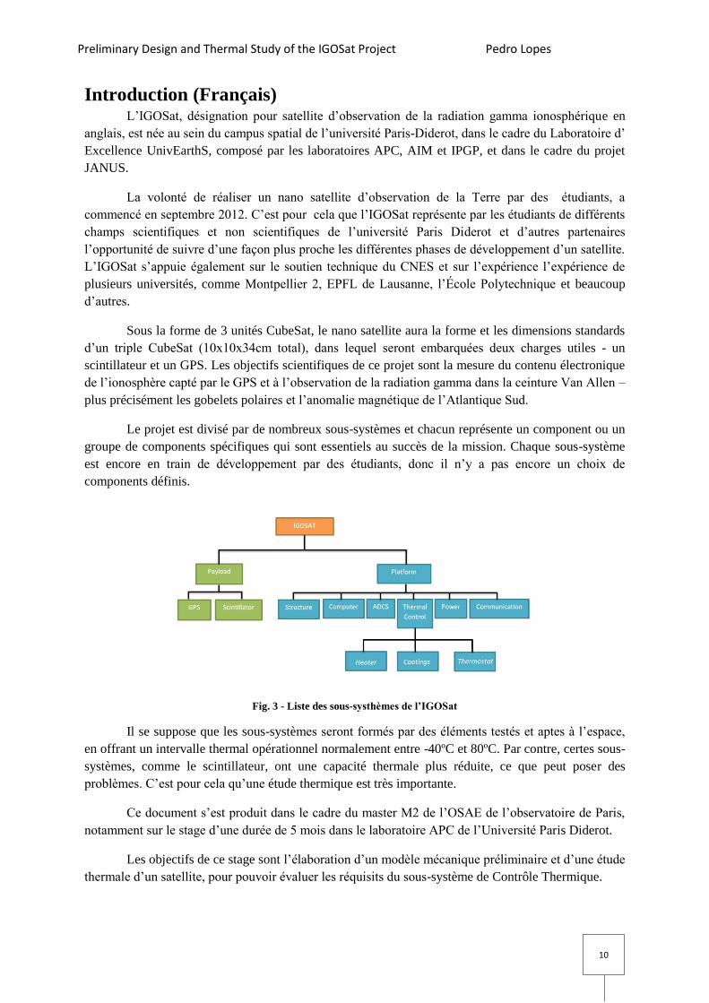
The project is divided in several subsystems, each referring to a specific component or set of
components that are critical to the success of the mission. Each subsystem has its own requirements
and specifications that must be taken into account when designing the satellite and are for the most
part, still in development by other students, hence there is no choice in components.
Fig. 1 - List of IGOSat's subsystems
The subsystems are expected to be formed by space ready and tested components that offer a
large thermal operational range to survive against the space environment – typically between -40ºC to
80ºC. However, there are subsystems such as the Scintillator that have a much smaller range than the
typical one. This could be a problem and it is why the thermal study is so important.
This paper is written as part of the master M2 OSAE from Paris Observatory, namely during a
5 months internship for the APC at the Paris Diderot University Space Campus.
The main objectives of this internship were to perform a preliminary mechanical design and a
thermal study of the satellite in order to evaluate the Thermal Control Subsystem requirements.
At the start of this internship there were no complete models available for any of the
components of the satellite. As so, I created a list of needed components for each subsystem, so that
the mechanical design could be developed.
Preliminary Design and Thermal Study of the IGOSat Project Pedro Lopes
9
Each component is designed with IDM-CiC and Google SketchUp, thus enabling the study of
different configurations and the identification of possible mechanical constraints.
Once the mechanical design is completed, the thermal design could be created, as it is based
on the mechanical one.
The thermal control subsystem is a key element for the stability and longevity of any satellite,
as it is responsible for monitoring and controlling the temperatures in the different components.
Furthermore, it can make use of both active and passive components to control these temperatures.
Subsequently, this report aims to identify the heat transfer mechanisms that are present in the
satellite and in the space environment in order to calculate the exchanged internal and external heat
fluxes.
Based on these last steps, a new thermal model is built with Systema & Thermica, the software
that allows the simulation of a space environment and its effects on a satellite. With the completion of
this thermal study, it will be possible to identify which equipments might be subjected to temperatures
outside their operational range and possibly, to provide solutions.
At the end of this report, I hope to have provided this project with two, simple working models
that might be the ground work on which future students will be able to improve and easily update.
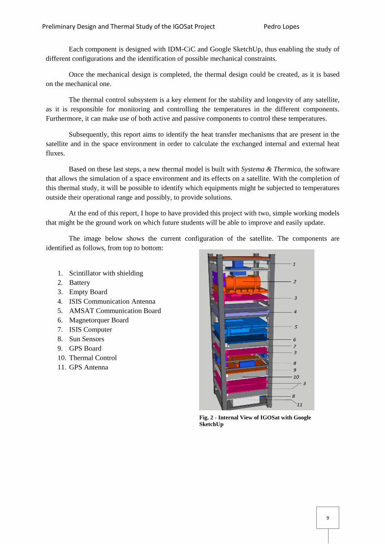
The image below shows the current configuration of the satellite. The components are
identified as follows, from top to bottom:
1. Scintillator with shielding
2. Battery
3. Empty Board
4. ISIS Communication Antenna
5. AMSAT Communication Board
6. Magnetorquer Board
7. ISIS Computer
8. Sun Sensors
9. GPS Board
10. Thermal Control
11. GPS Antenna
Fig. 2 - Internal View of IGOSat with Google
SketchUp
Preliminary Design and Thermal Study of the IGOSat Project Pedro Lopes
10
Introduction (Français) L’IGOSat, désignation pour satellite d’observation de la radiation gamma ionosphérique en
anglais, est née au sein du campus spatial de l’université Paris-Diderot, dans le cadre du Laboratoire d’
Excellence UnivEarthS, composé par les laboratoires APC, AIM et IPGP, et dans le cadre du projet
JANUS.
La volonté de réaliser un nano satellite d’observation de la Terre par des étudiants, a
commencé en septembre 2012. C’est pour cela que l’IGOSat représente par les étudiants de différents
champs scientifiques et non scientifiques de l’université Paris Diderot et d’autres partenaires
l’opportunité de suivre d’une façon plus proche les différentes phases de développement d’un satellite.
L’IGOSat s’appuie également sur le soutien technique du CNES et sur l’expérience l’expérience de
plusieurs universités, comme Montpellier 2, EPFL de Lausanne, l’École Polytechnique et beaucoup
d’autres.
Sous la forme de 3 unités CubeSat, le nano satellite aura la forme et les dimensions standards
d’un triple CubeSat (10x10x34cm total), dans lequel seront embarquées deux charges utiles - un
scintillateur et un GPS. Les objectifs scientifiques de ce projet sont la mesure du contenu électronique
de l’ionosphère capté par le GPS et à l’observation de la radiation gamma dans la ceinture Van Allen –
plus précisément les gobelets polaires et l’anomalie magnétique de l’Atlantique Sud.
Le projet est divisé par de nombreux sous-systèmes et chacun représente un component ou un
groupe de components spécifiques qui sont essentiels au succès de la mission. Chaque sous-système
est encore en train de développement par des étudiants, donc il n’y a pas encore un choix de
components définis.
Fig. 3 - Liste des sous-systhèmes de l’IGOSat
Il se suppose que les sous-systèmes seront formés par des éléments testés et aptes à l’espace,
en offrant un intervalle thermal opérationnel normalement entre -40ºC et 80ºC. Par contre, certes sous-
systèmes, comme le scintillateur, ont une capacité thermale plus réduite, ce que peut poser des
problèmes. C’est pour cela qu’une étude thermique est très importante.
Ce document s’est produit dans le cadre du master M2 de l’OSAE de l’observatoire de Paris,
notamment sur le stage d’une durée de 5 mois dans le laboratoire APC de l’Université Paris Diderot.
Les objectifs de ce stage sont l’élaboration d’un modèle mécanique préliminaire et d’une étude
thermale d’un satellite, pour pouvoir évaluer les réquisits du sous-système de Contrôle Thermique.

Preliminary Design and Thermal Study of the IGOSat Project Pedro Lopes
11
Au commencement de ce stage, il n’y avait pas de modèles complets disponibles pour aucun
élément du satellite. Par conséquence, j’ai créé une liste de components nécessaires pour chaque sous-
système pour que le modèle mécanique pût être conçu.
Chaque component a été créé par IDM-CiC et Google SketchUp, permettant l’étude de
différentes configurations et l’identification de possibles limitations mécaniques.
Une fois le modèle mécanique terminé, le modèle thermique peut être crée une fois que celui-
ci se base sur le premier.
Le sous-système de contrôle thermique est un élément clé pour la stabilité et longévité de
n’importe quel satellite, une fois qu’il est responsable pour monitorer et contrôler les températures des
différents components. En plus, il peut utiliser les component actifs et passifs pour contrôler les
températures.
Par conséquence, ce rapport a comme objectif d’identifier les mécanismes de transfert
thermiques présents sur le satellite et l’environnement spatial pour calculer les échanges de fluxes
internes et externes.
Basée sur ces dernières étapes, un nouveau modèle thermale est créé avec Systema &
Thermica, le logiciel de simulation de l’environnement spatial et de ces effets sur un satellite. Avec la
conclusion de l’étude thermale il sera possible d’identifier quels équipements ont un intervalle de
température hors de son intervalle opérationnel et, peut-être, suggérer des solutions.
A la fin de ce rapport, j’espère avoir créé deux modèles de travail simples et de facile
actualisation qui pourront fonctionner comme base pour l’avenir.
L’image à droite représente la configuration
actuelle du satellite. Ses components sont identifiés de la
façon suivante :
1. Scintillateur avec bouclier
2. Batterie
3. Plaque vide
4. Antenne de communication ISIS
5. Plaque de communication AMSAT
6. Plaque Magneto coupleur
7. Ordinateur ISIS
8. Senseurs solaires
9. Plaque GPS
10. Contrôle thermique
11. Antenne GPS
Fig. 4 - Visuel interne de l’IGOSat sur
Google SketchUp
Preliminary Design and Thermal Study of the IGOSat Project Pedro Lopes
12
2. Preliminary Design Preliminary design serves an important function as it allows a better visualization of:
1. The satellite layout;
2. The room available;
3. Mechanical constraints that are not easily visible by written specifications alone.
2.1 Introduction to IDM-CiC
The preliminary design was done using a software called IDM-CiC provided by the CNES,
which is a macro for Microsoft Excel. It simulates a Concurrent Design Facility by enabling the user
to create a project and define each subsystem. The same Excel file can then be used concurrently by
several teams, as they define the equipment of their subsystem, with access to only that subsystem.
Using IDM-CiC, each user can define the shape (cylinder, rectangle...), fields of view of
sensors, mass, operational temperatures, power modes and more. By adding more than one shape per
equipment and managing their relative position, the software allows the creation of more complex
equipment’s visual representations, which can be used to build a more complete model. The
equipment can then be visualized using a plugin for Google SketchUp.
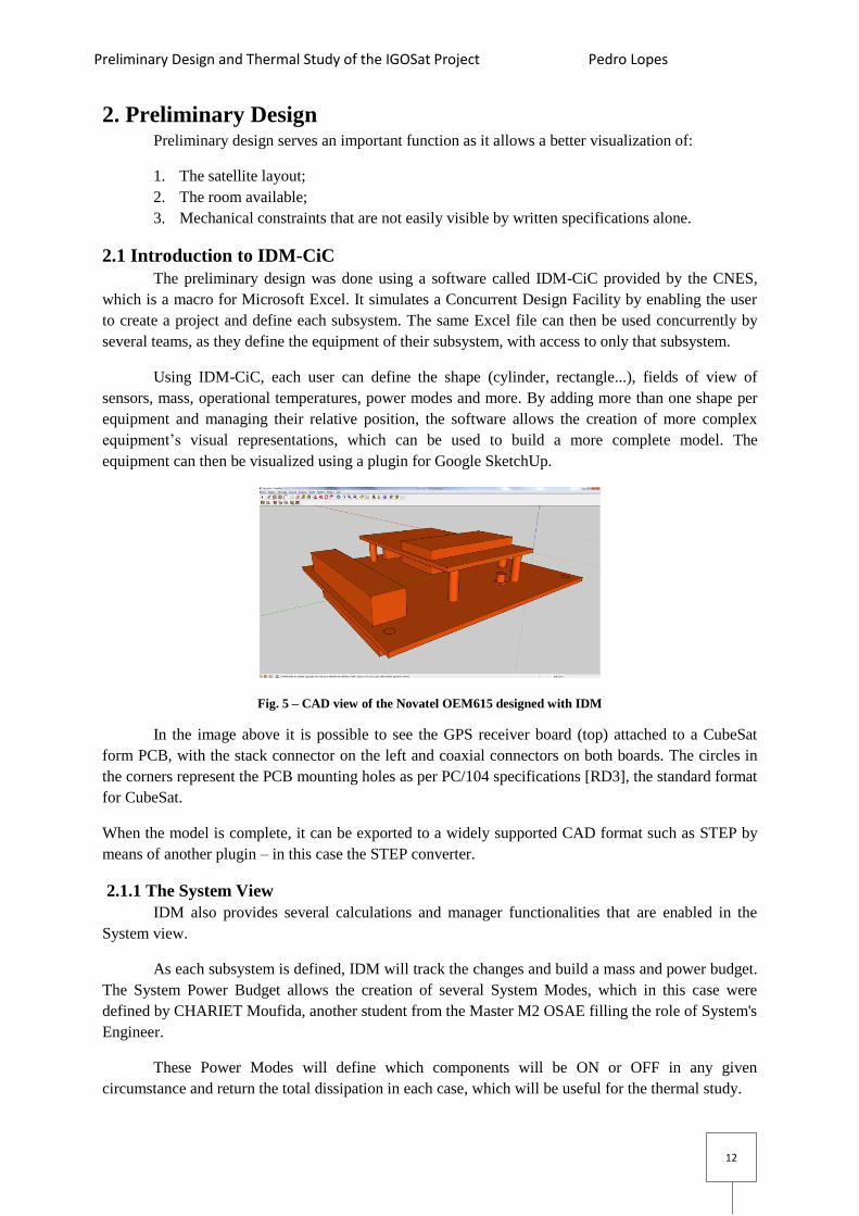
Fig. 5 – CAD view of the Novatel OEM615 designed with IDM
In the image above it is possible to see the GPS receiver board (top) attached to a CubeSat
form PCB, with the stack connector on the left and coaxial connectors on both boards. The circles in
the corners represent the PCB mounting holes as per PC/104 specifications [RD3], the standard format
for CubeSat.
When the model is complete, it can be exported to a widely supported CAD format such as STEP by
means of another plugin – in this case the STEP converter.
2.1.1 The System View
IDM also provides several calculations and manager functionalities that are enabled in the
System view.
As each subsystem is defined, IDM will track the changes and build a mass and power budget.
The System Power Budget allows the creation of several System Modes, which in this case were
defined by CHARIET Moufida, another student from the Master M2 OSAE filling the role of System's
Engineer.
These Power Modes will define which components will be ON or OFF in any given
circumstance and return the total dissipation in each case, which will be useful for the thermal study.

Preliminary Design and Thermal Study of the IGOSat Project Pedro Lopes
13
The System view will allow the overall configuration of the satellite (Annex 1), by allowing
each equipment position to change through manipulation of an Excel sheet. It will also calculate the
current system’s Centre of Gravity (COG), a key piece of information for the design as it will be
discussed in the next section.
The final result can then be seen using the Google SketchUp plugin.
2.2 Design Constraints
Design constraints can be divided into two categories:
1. The general constraints due to CubeSat rules (CDS Constraints)
2. Mission Specific Constraints, which are particular to each satellite
2.2.1 CDS Constraints
As per [RD4], the CubeSat construction is subject to several limitations and rules. The
constraints that have the greatest effect over the design are the dimensions and mass. A CubeSat can
exist in a variety of sizes, from the most basic one cube satellite, typically referred to as a 1U satellite
to larger 6U satellites.
As per [RD1] and [RD2], IGOSat is expected to be a 3U CubeSat, which means it will have
three cubes. These are assembled in a line following the Z direction. The following is a list of the
specifications that have the greatest impact on the satellite’s design:
CDS 2.2.5.1: The dimensions of a 3U satellite are of 100x100x340.5 mm;
CDS 2.2.6: The components cannot exceed 6.5mm outside the 100mm cube (9mm if using
ISIPOD [RD5]);
CDS 2.2.9: The contact rails between deployment pod and satellite must have a minimum
width of 8.5mm;
CDS 2.2.16: The mass of a 3U satellite cannot exceed 4.0kg;
CDS 2.2.17: The centre of gravity (COG) must be within a sphere of 20mm from the
satellite’s geometrical centre.
The best way to comply with most of these and the remaining specifications is to select a tested and
flight proven structure readily available on the market, also known as COTS (Components of the
Shelf).
The current design uses the ISIS CubeSat structure [RD5]. It was chosen due to its simple design,
good documentation and a significant difference in price when compared to the Pumpkin alternative.
With this choice the design complies with the better part of these constraints, however, the last two
will be design dependent and must be supervised.
2.2.2 Mission Specific Constraints
Besides the aforementioned constraints, there are also the limitations imposed by the mission
to consider. For these, one can refer to the Mission Specifications report [RD1] (translated from
French):
MS-4.8-9: For the (TEC) measurements, we will prioritize the descending occultations.

Preliminary Design and Thermal Study of the IGOSat Project Pedro Lopes
14
MS-4.2-14: To be able to perform any measurements, the (GPS) antenna needs to be pointed
to a GPS satellite: therefore an inboard ADCS (Attitude Determination and Control System) is
required to stabilize and point the satellite in the desired direction.
MS-4.2-15: The orientation and attitude control will be done in the 3 rotation axis.
MS-4.2-16: The antenna pointing to the GPS satellite must be placed in the back of the
satellite, in a way that is facing the direction opposed to the movement of the IGOSat.
These impose one special constraint in the design: the GPS antenna must be placed on the -Z
Plane.
As this work progressed, so did the study regarding the second payload: the scintillator.
According to [RD6], the performance of the instruments that form this payload will be affected mainly
by three factors:
Temperature - both the SiPM and the scintillator (LaBr3 crystal and plastic) have an optimal
operational temperature range between 0 and 40ºC;
Position - the scintillator needs as few physical obstructions as possible;
Shielding - the SiPM requires a significant amount of shielding on the lateral and bottom sides
to avoid particle detection from directions that do not come from the scintillator.
2.3 Designing IGOSat
2.3.1 Choosing the Components
In addition to the previous constrains, the constraints of the hardware that will be used in the
satellite should also be considered. However, since the project is still in early stages, some subsystems
have not been fully determined and are, therefore, lacking hardware specifications. For these
subsystems, the components used in the design were chosen based on the following priority list:
Most information available;
Flight heritage;
Compatibility with the mission and existing hardware.
The table below, lists each subsystem, their components, status (Determined or To Be Determined),
problems that arise from their use and possible solutions.

Preliminary Design and Thermal Study of the IGOSat Project Pedro Lopes
15
Subsystem Component Status Problem Solution Notes Structure ISIS 3U TBD --- --- ---
Command ISIS Computer TBD --- --- Allows
custom
daughter
board Power LFP26650EV
Battery Cell TBD Requires custom board
Low thermal range --- Might
require
heater Power Gomspace Nano
Power P110
series (Solar
Panel)
TBD Lower thermal range --- Higher
efficiency
ADCS Magnetometer TBD Usually placed in a boom far
from the satellite Place it in the cube
with less active
elements
No boom
planned
ADCS Magnetorquer TBD 3 coils (one for each axis) will
nearly need an entire cube Use a design
similar to ISIS or
use solar panel
with ADCS
ISIS uses an
air core
torquer that
requires less
room ADCS Sun Sensors TBD Must have a view of the
exterior --- ---
COM AMSAT-F D Smaller than CubeSat form;
requires special connector Use custom board Compatible
with ISIS
daughter
board COM ISIS UHF/VHF
Antenna TBD --- --- Fits between
the feet, can
take solar
panel and
ADCS GPS Novatel
OEM615 D Smaller than CubeSat form;
has two connectors (coaxial
and 20 pin)
Use custom board ---
GPS AeroAntenna
AT2775-103 TBD Dimensions (23mm tall) Must be attached
to a board inside
the satellite
Heritage:
CANX2
SCI EASIROC D Requires custom board --- --- SCI SiPM D Connects to EASIROC;
requires shielding; efficiency
depends on temperature
--- Might need
heater
SCI Scintillator D Requires a support to hold it
over the SiPM --- ----
Table 1- list of each subsystem and possible problems.

Preliminary Design and Thermal Study of the IGOSat Project Pedro Lopes
16
2.4 Assembling IGOSaT
The ISIS Structure is relatively complex to assemble. Each internal cube is formed by four
lateral ribs (two on top, and two on the bottom) and four vertical rods where the PCBs are stacked.
The structure is enclosed by two aluminium side frames that form the feet, rails and remaining ribs.
Fig. 6 - Disassembled 1U CubeSat (credit: ISIS)
In the above image we can see the components of a cube, from left to right:
Aluminium TSP(2x) and SSP(4x), Side Frames Black Anodised with attached kill switch(2x), Boards,
Ribs Blank alodyned (4x), M3 Threaded Rods (4x), several M3 Bus spacers, Hex Nuts and Washers.
Since IGOSat is a 3U CubeSat, each side frame will be 340mm tall and 100mm wide and will enclose
the three cubes. As this configuration is simply an extension of the simple 1U configuration, there will
be some free space between each stack, which will be equivalent to twice the feet height of the satellite
(approximately 14mm between cubes).
There are two stack options available:
Custom 94x94 boards: vertical clearance between boards of 13mm;
Standard PC/104 boards: vertical clearance between boards of 14mm.
The stack option chosen was the standard for PC/104
PCB as these are the ones most readily available as
COTS, and are approximately 90x96mm.
Communication between boards is assured by a 104 pin
stack through connector as per PC/104 specifications.
This stack has a maximum distance of 75mm between
ribs, which assuming the thickness of the PCB as 1.6mm
and the necessary clearance for the stack connectors of
14mm gives a total maximum of five PCBs per stack.
Each PCB is usually separated by a 12 mm aluminium
spacer and four washers of 0.5mm thickness each.
This internal organization should work fine for regular
sized components. However, given some mechanical
constraints, some stacks had to be slightly adapted in
some cases. Fig. 7 - General internal organization of a cube as per ISIS.

Preliminary Design and Thermal Study of the IGOSat Project Pedro Lopes
17
2.4.1 Cube 1
The first cube (lower cube) contains for the most part, the GPS system, empty boards and
potentially the Thermal Control board and magnetometer.
The magnetometer can be very small - about the size of a 5 cents coin - and it is used to
measure the magnetic field in order to make the ADCS able to change the satellite's attitude.
To do this, the device needs to have as little magnetic interference as possible coming from the
other electronic devices. This is the reason why the magnetometer is typically deployed outside the
satellite. Usually to do this a boom similar to what was done in CanX-2, a student satellite from
Canada [OR1], is used.
As for this project there is no boom planned, the magnetometer could benefit from being in the
first cube if the GPS is not going to be operational at all times (To be determined).
The current GPS antenna is over 2cm thick, which means it cannot be placed on the surface of
the satellite as it would violate CDS 2.2.6. Consequently, the antenna was placed on a PCB board that
is secured in the internal stack of the lower cube.
For this cube, and in order to be able to follow the internal organization suggested by ISIS,
the Hex Nut M3 was placed on the bottom ribs. This small change in placement allows the antenna to
have only 2-3 millimetres outside the cube respecting CubeSat Specifications.
After the GPS antenna, the stack is formed by two empty boards - the Thermal Control and
finally the Novatel OEM 615 GPS receiver. The latter, being smaller than CubeSat standard, needs to
be placed in a CubeSat format PCB that fits the specifications.
The Novatel OEM615 GPS receiver can be attached to the PCB with 12 mm Hex Stands and
screws. This extra height and the dimensions of the small board together with its electronic parts are
the reason why this receiver was placed on the top of the stack. Overall, this component would need a
vertical clearance larger than the typical 14mm allowed between PCBs but in this position it can make
use of the free space between cubes.
Fig. 8 - Cube 1 Internal Layout
14mm

Preliminary Design and Thermal Study of the IGOSat Project Pedro Lopes
18
2.4.2 Cube 2
Cube 2 is home to part of the ADCS, computer and communications subsystems. The ADCS
is composed of several instruments such as the magnetorquers for attitude control, magnetometer and
sun sensors for attitude determination. Due to its complexity, it creates some potential technical
problems for the design.
The list presented on Table 1 was compiled based on the information available before the
preliminary design was done. However, it became evident upon completion of the first design that, for
some subsystems such as the ADCS, the three rod torquers with a length of 70mm being considered
were impractical. Such configuration meant that the third torquer (vertical) would require a full cube,
otherwise it would intersect any PCB board placed there. This subsystem was then replaced by a
similar ISIS Magnetorquer board design that makes use of an air core torquer, of much smaller
dimensions than the rods, and it was placed under the PCB to replace the vertical rod.
Fig. 9 - ISIS Magnetorquer Board (source: CubeSatShop.com)
One other problem comes from the Sun Sensors. These, as the name suggests, are used to
determine the position of the Sun and would require a full coverage of the sky. Four of these sensors
are placed on the side panels, in the space between cubes 1 and 2, facing out between the solar panels.
However, the top and bottom sides might prove impractical for Sun Sensors placement.
Although the current placeholder allows enough room around the antenna for a sensor to be placed, the
bottom is occupied by the GPS antenna, and depending on the final antenna it might not have room for
a sun sensor. The top side is completely occupied by a solar panel leaving no room for a sensor. One
option however, is to use a solar panel with integrated sun sensor which is available from most sellers.
The choice of the computer will affect mostly how the communication board can be
connected, since it is smaller than PC/104 specifications. If the chosen computer accepts a custom
daughter board, such as the ISIS option or the Cube Computer, the AMSAT board can be placed on
the computer and will require less clearance upwards.

Preliminary Design and Thermal Study of the IGOSat Project Pedro Lopes
19
Fig. 10 – Cube computer with and without daughter board
Otherwise, a computer without this option will mean that the AMSAT board will require an
extra custom PCB to fit the CubeSat standard format, requiring more vertical clearance since there is a
minimum 13-14mm average distance between each PCB due to the stack connectors as seen in Fig. 8.
However, this configuration would have the advantage that the communication board and computer
would be independent from each other and would not affect their placement. For this study a version
without daughter board will be used as it is the most generic option and would be compatible with any
computer.
The final layout for this cube is similar to cube 1's distribution but with one less PCB, whose
place is occupied by the AMSAT, and with only 13mm between boards. These changes were
necessary due to the irregular size of the AMSAT board, which is by default composed by two small
PCBs stacked with a separation of 5mm, as seen in the image below. This is then aggravated by the
need of this component to be placed in another PCB with at least an 11-12mm clearance to
accommodate the SSQ-114-21-G-D connector as per AMSAT specifications [RD7].
Fig. 11 - Internal Layout of Cube 2
13mm
10mm
Preliminary Design and Thermal Study of the IGOSat Project Pedro Lopes
20
2.4.3 Cube 3
The final cube houses the battery and the second payload, which is a LaBr3 scintillator. Both
equipment lower temperature operational limits are shorter than most other components: -20ºC for the
battery and 0ºC for the Silicone Photo Multiplier (SiPM - responsible for the detection of events in the
LaBr3 crystal). Since both might require a heater, they were placed in close proximity so that both
could benefit from the same heat source.
One other reason for these two components to be in the same cube is due to mechanical
restrictions. The battery cell is a cylinder with 26.5mm diameter, which means it can't follow the same
internal organization that the other cubes follow.
The scintillator payload main components are the crystal with plastic scintillator, the SiPM, a
high voltage generator to power the SiPM and the EASIROC (Extended Analogue SI-pm ReadOut
Chip from OMEGA Micro) that is dedicated to read the SiPM.
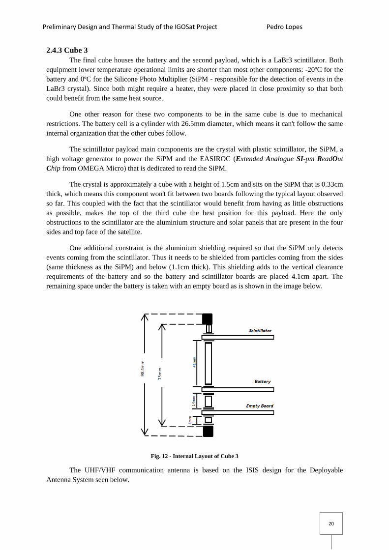
The crystal is approximately a cube with a height of 1.5cm and sits on the SiPM that is 0.33cm
thick, which means this component won't fit between two boards following the typical layout observed
so far. This coupled with the fact that the scintillator would benefit from having as little obstructions
as possible, makes the top of the third cube the best position for this payload. Here the only
obstructions to the scintillator are the aluminium structure and solar panels that are present in the four
sides and top face of the satellite.
One additional constraint is the aluminium shielding required so that the SiPM only detects
events coming from the scintillator. Thus it needs to be shielded from particles coming from the sides
(same thickness as the SiPM) and below (1.1cm thick). This shielding adds to the vertical clearance
requirements of the battery and so the battery and scintillator boards are placed 4.1cm apart. The
remaining space under the battery is taken with an empty board as is shown in the image below.
Fig. 12 - Internal Layout of Cube 3
The UHF/VHF communication antenna is based on the ISIS design for the Deployable
Antenna System seen below.

Preliminary Design and Thermal Study of the IGOSat Project Pedro Lopes
21
Fig. 13 - ISIS antenna and ISIS structure (credit: CubeSatShop.com)
Figure 12 shows the ISIS structure with the side frames in black and ribs in blank alodyned. At
the back it is possible to see another satellite with the SSP.
Typically this device is screwed to the side frames and positioned between the feet of the
structure. However since the GPS antenna already occupies one of these faces and in the other face it
would obstruct the scintillator, the only place left is between Cube 2 and 3.
This placement is made possible by the antenna model with a 3cm diameter hole for pass-
through cables to connect cube 2 to cube 3. Otherwise, the antenna would block the stack connectors
that link all the boards together making impossible the communication between them.
2.4.4 Fulfilling Design Specifications
The sole intent of the distribution described above was to fulfil the requirements imposed by
the design constraints mentioned in section 2.2. The MS constraints are easily respected by placing the
GPS antenna in the lower cube attached to a PCB in the internal stack. The CDS and mechanical
constraints imposed by the components however, require some additional considerations.
The empty boards are present to provide balance and to help follow the correct internal
organization of the PCBs, this not only makes it easier to keep the satellite organized and balanced but
also helps considerably in the calculation of the thermal links later on.
One important consequence of the decisions taken so far is concerning the solar panels. These
components are available in different sizes: 1U, 2U and 3U, each covering the totality of a face
corresponding to one, two or three cubes and are screwed to the structure's ribs. However, since the
space between cubes is occupied by other instruments such as the Sun Sensors and the communication
antenna, the larger configurations are no longer compatible. Therefore, IGOSat is powered by a total
of thirteen 1U solar panels that are distributed around the four sides and top face of the satellite.
With this configuration, the satellite has a total mass of 2,8 kg (with 20% mass margin), well
within the limit of 4 kg imposed by CDS 2.2.16 and leaves a margin of 1,2 kg to account for spacers,
washers and cables that were not modelled and any other component that might be added in the future.
The centre of gravity reported by IDM-CiC is located at X= -0,29 mm, Y= 2,93 mm and Z= -0,3 mm
in relation to the geometrical centre of the satellite, which is well within the expected coordinates
imposed by CDS 2.2.17 and can be further adjusted by adding mass to the empty boards.

Preliminary Design and Thermal Study of the IGOSat Project Pedro Lopes
22
3. Heat Transfer Mechanisms: Theoretical Background There are typically three mechanisms for heat transfer: Conduction, Radiation and Convection.
However, since the satellite will be at a rather large altitude (600km), the latter is negligible since there
will be little influence from the atmosphere [RD8]. To perform this study, a nodal model was created,
where each component is reduced to a single isothermal node and the links between each node are
calculated for each type of transfer mechanism. Therefore, the following definitions are done in such
context providing the basis for those calculations.
3.1 Conduction
Conduction is ruled by Fourier's Law and occurs when two bodies (gas, liquids or solids) are
placed in contact, or between two points in the same body due to the temperature gradient between
them, with heat flowing from the hotter to the colder point.
For the purpose of this study, the conduction links are defined by the thermal conductance
(GL in W/K units), that refers to the quantity of heat passing through a body.
The value of the GL can then be easily calculated from Fourier's equation for heat transfer:
(Eq.1)
The inverse of this concept is called Thermal Resistance Rth (K/W), which is given by:
Rth =
(Eq.2)
Given a series of resistances, the total resistance is given by the sum of resistances that form the path.
This is particularly useful because as seen in chapter 2, the link between two PCBs is often made of
more than one body, and so the thermal conductance is given by:
Rth total = ∑ <=>
∑ (Eq.3)
When the heat flow is parallel, like the case of four parallel spacers that link one PCB to the next or
the dual connection between a PCB and a rib, the equivalent conductance is given by the sum of the
conductance:
<=> GLtotal = GL1 + GL2 (Eq.4)
dQ/dt =heat flow (W, J/s)
k = heat conductivity (W/m.K)
F = area of the heat flow (m2)
T = temperature gradient
between the two points (K)
d = distance between the two
points (m)

Preliminary Design and Thermal Study of the IGOSat Project Pedro Lopes
23
Fig. 14 - Front, side and top view of the internal stacks
Fig 14 represents the internal stacks’ views, showing the number and type of connections that are
made between PCB/PCB and PCB/Rib.
Since the internal organization of the stacks described in chapter 2 is rather regular for Cubes 1 and 2,
most of the links need only to be calculated once, with the sole variation from one cube to the other
being that the link PCB/PCB has less two washers in Cube 2.
These links will be fundamental for the satellite’s internal heat transfers and will require detailed
knowledge of the interfaces for each component. Since Systema & Thermica's conduction module
proved too complex and required a very detailed model in order to allow automatic calculation of
these links, the calculations were done without the aid of the software and are presented in the next
chapter.
3.2 Thermal Radiation
Thermal Radiation is the process by which the heat transfers through electromagnetic waves.
It depends on the optical thermal property of the emitting body known as emissivity and its
temperature.
The emitted energy is given by:
(Eq.5)
F= surface area
T= temperature
= Stefan-Boltzmann constant
= emissivity
For this study, the value needed is the radiative coupling (GR) between two nodes that
depends on their emissivity and view factor. Systema & Thermica allows for the automatic calculation
of these values by using Monte-Carlo Ray-Tracing.

Preliminary Design and Thermal Study of the IGOSat Project Pedro Lopes
24
3.3 Space Environment
In-orbit satellites are subjected to a very particular environment that is dependent of their orbit,
time of the year and optical thermal properties of the satellite. There are three main sources of heat that
should be considered: Solar Flux, Albedo Flux and Planetary Flux.
Solar Flux relates to solar activity and can vary with time. As the planet orbits the Sun, the
relative distance between the two will change as well, causing a variation on the amount of solar flux
received by the planet and orbiting satellites. There are however, two positions of interest for the
thermal study, which are the northern winter and summer Solstices (Hot and Cold Cases). At these
dates, the planet will be at the farthest and closest position from the Sun respectively and the Solar
Flux will have a maximum and minimum value at these points.
Albedo Flux also relates to Solar Flux, but more precisely to the amount of Solar Flux that is
reflected by the Earth (or another celestial body) back to space. Albedo is a reflection coefficient that
depends on the surface at which the satellite is looking at. Values can range from 0.05 to 0.6
depending if we are looking at clouds, trees, water, etc... But an average value of 0.3 can be assumed
for a spacecraft [RD8]. The Planetary Flux is the heat flux released by the planet in the infrared
spectrum due to its surface temperature.
The final element of this environment is Space which acts as a heat sink for all other objects
and has a temperature of 3K. As these elements are radiation based, their values will also be
determined using Systema & Thermica.
Preliminary Design and Thermal Study of the IGOSat Project Pedro Lopes
25
4. Thermal Interfaces Another important factor to be taken into account is the interaction of each component with its
surroundings in terms of heat transfer. From the previous section it was observed that the two
predominant forms of heat transfer will be conduction and radiation. However, the amount of this
transfer will depend on the interface between a component and its surroundings.
4.1 Thermal Properties
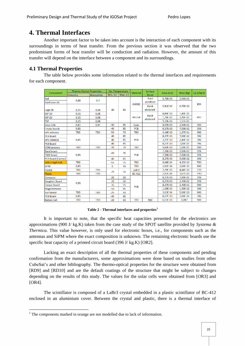
The table below provides some information related to the thermal interfaces and requirements
for each component.
Table 2 - Thermal interfaces and properties1
It is important to note, that the specific heat capacities presented for the electronics are
approximations (900 J/ kg.K) taken from the case study of the SPOT satellite provided by Systema &
Thermica. This value however, is only used for electronic boxes, i.e., for components such as the
antennas and SiPM where the exact composition is unknown. The remaining electronic boards use the
specific heat capacity of a printed circuit board (396 J/ kg.K) [OR2].
Lacking an exact description of all the thermal properties of these components and pending
confirmation from the manufacturers, some approximations were done based on studies from other
CubeSat’s and other bibliography. The thermo-optical properties for the structure were obtained from
[RD9] and [RD10] and are the default coatings of the structure that might be subject to changes
depending on the results of this study. The values for the solar cells were obtained from [OR3] and
[OR4].
The scintillator is composed of a LaBr3 crystal embedded in a plastic scintillator of BC-412
enclosed in an aluminium cover. Between the crystal and plastic, there is a thermal interface of
1 The components marked in orange are not modelled due to lack of information.

Preliminary Design and Thermal Study of the IGOSat Project Pedro Lopes
26
aluminium. However, the exact specifications of this interface are not known, neither are the thermal
properties of the plastic such as specific heat capacity. Without this information, it is not possible to
build an accurate thermal study, and as a consequence, this study will be done assuming a full cube of
LaBr3 for which the specific heat capacity is known [RD11].
One additional component that was suppressed from this model was the High Voltage
Generator that will power the SiPM. According to the manufacturer it consists of two small PCBs and
a transformer with a ferrite pot core. The transformer is soldered with RoHS compliant solder to both
PCBs and is held with tape and epoxy potting compound inside the case. Since it has a significant
amount of dissipation (0,5W) and a rather large operational temperature range (-55 to 75ºC) its
dissipation was placed on the EASIROC micro controller card that will support the scintillator
payload.
4.2 Conductive Interfaces
The following table lists the thermal interfaces for the conductive links. These can be formed
due to contact between surfaces, like SSP to Structure or Solar Panel to SSP, where these components
are screwed together or through other interfaces such as adhesives or spacers:
Connection Type of Interface Quantity Area (m2)
(per contact) Material
Side frame / Ribs Screw M2.5 8 1,59E-5 Stainless Steel SSP / Structure Screw M2.5 16 1,59E-5 Stainless Steel
Solar Panel / SSP Screw M2.5 4 1,59E-5 Stainless Steel Solar Panel /
Battery Molex PicoBlade Cable - - -
Ribs / Stack Rods Screw M3 4 2,38E-5 Stainless Steel GPS antenna/PCB Screw M3 3 2,38E-5 Stainless Steel
GPS antenna /
Receiver Coaxial Cable - - -
GPS Novatel
OEM615 / PCB M3 Hex Standoff + Stack
(28pins) 4 M3: 1,59E-5
Pin: 5,08E-7 Aluminium /
Phosphorous Bronze
(pins) COM Antenna/Ribs Screw M2.5 4 1,59E-5 Stainless Steel COM Antenna/PCB Coaxial cable to AMSAT +
Power cable to battery - - -
AMSAT/PCB M3 Spacer + Washer + Stack
(28pins) 4 M3: 1,59E-5
Pin: 5,08E-7 Aluminium /
Phosphorous Bronze
(pins) LaBr3 / BC-412 Aluminium* - TBD TBD
High Voltage Gen /
PCB Solder* TBD TBD TBD
SiPM/Crystal Silicone adhesive (0.5um) 1 2,97E-4 Silicone [OR6]* SiPM/PCB
(EASIROC) Pins 32 1,59E-7 Phosphorous bronze*
Sun Sensor/SSP Screw M1* 3 3,14E-6 Stainless Steel Sun Sensor/ADCS Cable* - - - Battery Cell/PCB Surface Contact + support* - TBD TBD
PCB/Rib Spacer + Washer varies varies Aluminium PCB/PCB Spacer + Washer +Stack
Connector varies varies Aluminium /
Phosphorous Bronze
(pins) Magnetometer /
PCB 9 pin micro D connector* - 1,96E-7 Gold Plated Copper
Kill Switch / Rail Screw M1.6 2 Stainless Steel Table 3: Conduction Thermal Interfaces (*to be confirmed)
Preliminary Design and Thermal Study of the IGOSat Project Pedro Lopes
27
Silicon Adhesive Spacers -
Aluminium
1050A H08
Standoff -
Aluminium
ASTM B211
(7075)
Pins -
Phosphorous
Bronze
Pins - Gold
Plated Copper
k (W/m K) 0.39 229 175 75 314 Table 4: Thermal conductivity for some interfaces (OR6, 7, 8, 9)
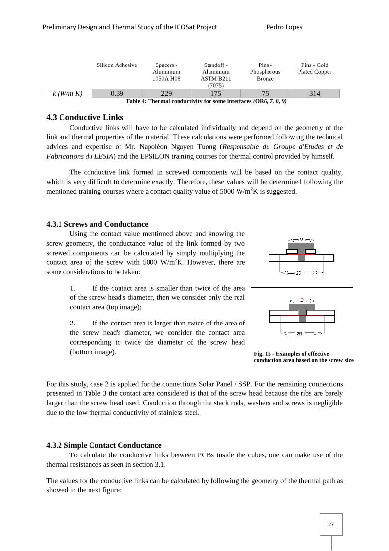
4.3 Conductive Links
Conductive links will have to be calculated individually and depend on the geometry of the
link and thermal properties of the material. These calculations were performed following the technical
advices and expertise of Mr. Napoléon Nguyen Tuong (Responsable du Groupe d'Etudes et de
Fabrications du LESIA) and the EPSILON training courses for thermal control provided by himself.
The conductive link formed in screwed components will be based on the contact quality,
which is very difficult to determine exactly. Therefore, these values will be determined following the
mentioned training courses where a contact quality value of 5000 W/m2K is suggested.
4.3.1 Screws and Conductance
Using the contact value mentioned above and knowing the
screw geometry, the conductance value of the link formed by two
screwed components can be calculated by simply multiplying the
contact area of the screw with 5000 W/m2K. However, there are
some considerations to be taken:
1. If the contact area is smaller than twice of the area
of the screw head's diameter, then we consider only the real
contact area (top image);
2. If the contact area is larger than twice of the area of
the screw head's diameter, we consider the contact area
corresponding to twice the diameter of the screw head
(bottom image).
For this study, case 2 is applied for the connections Solar Panel / SSP. For the remaining connections
presented in Table 3 the contact area considered is that of the screw head because the ribs are barely
larger than the screw head used. Conduction through the stack rods, washers and screws is negligible
due to the low thermal conductivity of stainless steel.
4.3.2 Simple Contact Conductance
To calculate the conductive links between PCBs inside the cubes, one can make use of the
thermal resistances as seen in section 3.1.
The values for the conductive links can be calculated by following the geometry of the thermal path as
showed in the next figure:
Fig. 15 - Examples of effective
conduction area based on the screw size
Preliminary Design and Thermal Study of the IGOSat Project Pedro Lopes
28
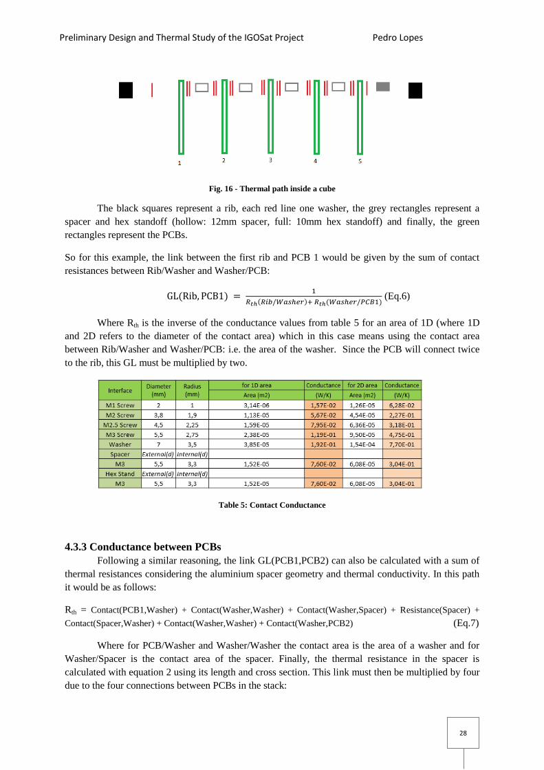
Fig. 16 - Thermal path inside a cube
The black squares represent a rib, each red line one washer, the grey rectangles represent a
spacer and hex standoff (hollow: 12mm spacer, full: 10mm hex standoff) and finally, the green
rectangles represent the PCBs.
So for this example, the link between the first rib and PCB 1 would be given by the sum of contact
resistances between Rib/Washer and Washer/PCB:
(Eq.6)
Where Rth is the inverse of the conductance values from table 5 for an area of 1D (where 1D
and 2D refers to the diameter of the contact area) which in this case means using the contact area
between Rib/Washer and Washer/PCB: i.e. the area of the washer. Since the PCB will connect twice
to the rib, this GL must be multiplied by two.
Table 5: Contact Conductance
4.3.3 Conductance between PCBs
Following a similar reasoning, the link GL(PCB1,PCB2) can also be calculated with a sum of
thermal resistances considering the aluminium spacer geometry and thermal conductivity. In this path
it would be as follows:
Rth = Contact(PCB1,Washer) + Contact(Washer,Washer) + Contact(Washer,Spacer) + Resistance(Spacer) +
Contact(Spacer,Washer) + Contact(Washer,Washer) + Contact(Washer,PCB2) (Eq.7)
Where for PCB/Washer and Washer/Washer the contact area is the area of a washer and for
Washer/Spacer is the contact area of the spacer. Finally, the thermal resistance in the spacer is
calculated with equation 2 using its length and cross section. This link must then be multiplied by four
due to the four connections between PCBs in the stack:

Preliminary Design and Thermal Study of the IGOSat Project Pedro Lopes
29
∑ (Eq.8)
If there is also a stack connector linking two PCBs, then this contribution is added to the
previous link. Since the stack connector and the path through the spacers are in parallel, the
conductances of the two links are added together instead of the thermal resistances. The pins (104
pins) are phosphorous bronze, as per [RD3] with an area of 5.08E-7 m2.
The link becomes:
∑ (Eq.9)
With
(Eq. 10)
4.3.4 Interface SiPM/Scintillator
This interface is not yet fully determined, but it is assumed that for this connection a silicone
pressure sensitive adhesive with a thickness of 0.5 microns will be used. For this simulation, the
values used are from [OR6].
The link is calculated using the result of Eq.1 for the full area of the SiPM.
4.3.4 Interface SiPM/PCB
The exact connector is also not determined, but the SiPM uses 32 pins to connect to the PCB.
The conductive link can be determined using Eq.10.
4.3.4 Interface Battery Cell/PCB
This subsystem is not fully developed, however it is known that the cell is going to be laying
down in the PCB and will require a support to brace the cell to the PCB. Conduction in this case
would be done in three parts:
1. Contact Cell/PCB;
2. Contact Cell/Support;
3. Contact Support/PCB;
Since there are too many unknowns, the link is determined by assuming that the battery is screwed to
the PCB with four M3 screws.
4.3.5 Interface Magnetometer/PCB
This magnetometer uses a 9 pin micro D connector. The pins are gold plated copper, with an
assumed length of 1mm, a diameter of 0,5um and an area of 1,96E-7 m2.
The link is calculated using Eq.10.
4.3.6 Interface Kill Switch/Side frame
CubeSat also requires a device called kill switch. Its task is to keep the satellite inactive during
launch, and activate it short after the CubeSat is deployed.
The kill switch used by the ISIS structure is the Panasonic AV4 micro switch (AV402461)
[RD5] that uses a travelling pin at the feet of the structure to activate the switch. The structure makes
use of two of these switches, one for each side frame. Each switch has 0.3 grams and an operating
Preliminary Design and Thermal Study of the IGOSat Project Pedro Lopes
30
temperature range between -25ºC to 80ºC. The switch is screwed with M1.6 screws and an aluminium
Al6082 bracket to the rails.
Since the temperature range is large and ISIS thermal cycling testing results did not report any
adverse effects to the operation of the switch at temperatures below -25ºC, this device is not modelled
in the current version of the satellite’s thermal model. Given the high thermal conductivity of
aluminium, it is assumed that the switch temperature will be approximately the same as the rails.
Later, depending on the results or for a more detailed model, the switch can be added.
Similarly, the same behaviour is expected to happen to the Sun Sensors that are screwed to the
SSPs, however since there is no information regarding their capacity to operate outside their thermal
ranges, they were modelled and will be studied later on.
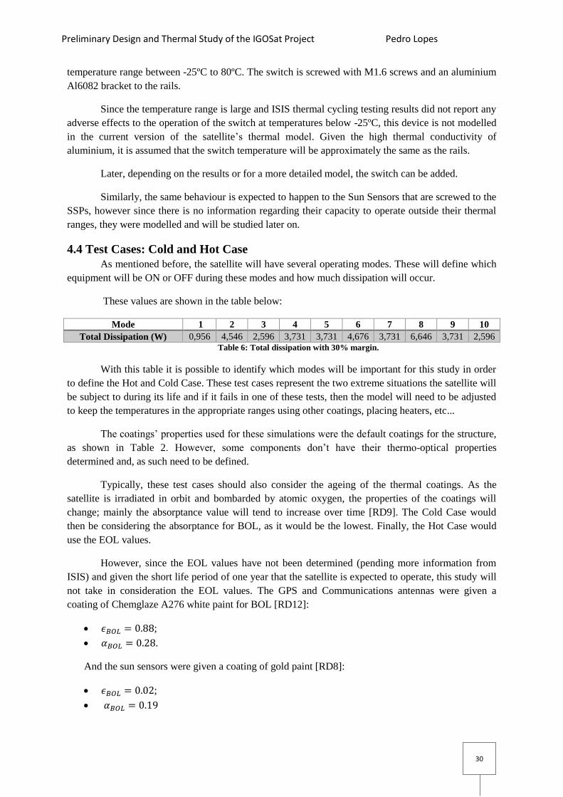
4.4 Test Cases: Cold and Hot Case
As mentioned before, the satellite will have several operating modes. These will define which
equipment will be ON or OFF during these modes and how much dissipation will occur.
These values are shown in the table below:
Mode 1 2 3 4 5 6 7 8 9 10
Total Dissipation (W) 0,956 4,546 2,596 3,731 3,731 4,676 3,731 6,646 3,731 2,596 Table 6: Total dissipation with 30% margin.
With this table it is possible to identify which modes will be important for this study in order
to define the Hot and Cold Case. These test cases represent the two extreme situations the satellite will
be subject to during its life and if it fails in one of these tests, then the model will need to be adjusted
to keep the temperatures in the appropriate ranges using other coatings, placing heaters, etc...
The coatings’ properties used for these simulations were the default coatings for the structure,
as shown in Table 2. However, some components don’t have their thermo-optical properties
determined and, as such need to be defined.
Typically, these test cases should also consider the ageing of the thermal coatings. As the
satellite is irradiated in orbit and bombarded by atomic oxygen, the properties of the coatings will
change; mainly the absorptance value will tend to increase over time [RD9]. The Cold Case would
then be considering the absorptance for BOL, as it would be the lowest. Finally, the Hot Case would
use the EOL values.
However, since the EOL values have not been determined (pending more information from
ISIS) and given the short life period of one year that the satellite is expected to operate, this study will
not take in consideration the EOL values. The GPS and Communications antennas were given a
coating of Chemglaze A276 white paint for BOL [RD12]:
;
.
And the sun sensors were given a coating of gold paint [RD8]:
;

Preliminary Design and Thermal Study of the IGOSat Project Pedro Lopes
31
4.4.1 Cold Case
This test case consists of the scenario where the satellite will have the lowest amount of
internal dissipation and external fluxes. For the external fluxes, this will be in the Summer Solstice
when the Earth is in the aphelion and will affect mostly the Solar Flux and Albedo.
The internal dissipation that fits the requirements is mode 1. To better approximate to the
worst cold case scenario, the 30% margin is removed which gives a total dissipation of 0,72 W.
The equipment active on this mode will be:
Equipment Dissipation (W)
Battery 0,128
Computer 0,4
Communication (AMSAT) 0,195
Com. Antenna <0,02* Table 7: Internal dissipation in the Cold Case
4.4.2 Hot Case
The Hot case consists on the opposite scenario, where the satellite will have the highest
amount of internal dissipation and external fluxes. This happens in the Winter Solstice, which means
in the perihelion.
The mode chosen is mode 8 with a total dissipation of 6,56W, this time accounting for the
extra 30% dissipation to really represent the worst case scenario. The equipment active on this mode
will be:
Equipment Dissipation (W)
Battery 0,162
Computer 0,52
Communication (AMSAT -RX) 0,254
Com. Antenna <0,02*
Torquer Board 0,815
Sun Sensor (x5) 0,065
Magnetometer 0,52
GPS Receiver 1,43
GPS Antenna 0,65
EASIROC (SCI) 1,95** Table 8: Internal dissipation in the Hot Case
Notes:
- AMSAT -RX stands for reception mode;
- *nominal dissipation as per supplier specifications : we use 0,02 W for the simulations;
- **it includes the dissipation from the EMCO High Voltage Generator that powers the SiPM and the
dissipation from EASIROC.

Preliminary Design and Thermal Study of the IGOSat Project Pedro Lopes
32
5. Thermal Study This Thermal Study is performed using the Systema & Thermica 4.6.1 software, provided by
Airbus Defence and Space and recommended by the CNES. The software provides an all-in one
interface that allows the creation of the spacecraft geometry and defines its orbit, kinematics and
mission scenario. This information can then be used to compute the fluxes and calculate the
temperature variation for each component of the model. The next sections will provide a short
introduction on how the software works.
5.1 Systema & Thermica
5.1.1 Modeler and Mesh
The modeller allows the creation of the geometry by assembling basic geometries (rectangles,
boxes, etc..). It is possible to import CAD models which would have allowed us to import the
geometry built with IDM-CiC or even use the STEP files provided by the manufacturers. However, it
was decided to create a new geometry using Systema & Thermica.
Here is also where material properties are defined, such as coatings (absorptance and
emissivity), density, etc... That will be used for the computation later on.
The mesh, which is a collection of nodes, is created from the geometry. By default, each face
of a box or of a rectangle is a different node, but the numbering of the nodes can be changed to fit our
purposes. Below the list of nodes and corresponding component is shown:
Subsystem Node Equipment Shapes
1-28 Rails and ribs Rail: Rectangles ; Rib: Box
STRUCTURE 29-38 Side Shear Panels Rectangles
40, 50, 60, 70 Empty PCB Rectangles
TC 80 Thermal Control Board Rectangles GPS 100-101 GPS antenna and support board Antenna: Box ; Board:
Rectangle
200-201 GPS OEM615 and support board Rectangles
COM 300 Antenna Box
400-401-402 AMSAT (RX-TX + Pass Band) Rectangles
500 EASIROC and PCB Rectangles
SCI 600 SiPM Box
700-800* LaBr3 crystal and BC-412 plastic
scintillator Box
CPU 900-901 Computer and daughter board Rectangles
1000 Torquer Board Rectangles
ADCS 1100 Magnetometer Box
1200-1500,1501 Sun Sensors Internal: Rectangle ; External: Circle
1600-1601 Battery board and cell Board: Rectangle ; Cell: Cylinder
1700, 1800,…, 2900 Solar Panels Rectangles
Total 79 nodes Table 9: Identification of the Model’s Nodes (*not used in the model)
For simplicity, the internal components were designed as one node per equipment and use
simple individual shapes, or as in the case of the structure, a collection of different shapes with
individual nodes.

Preliminary Design and Thermal Study of the IGOSat Project Pedro Lopes
33
Each side frame is a single element that includes two rails and six ribs and where each rail
forms a corner. Since there is no natural shape that looks like this, each rail was modelled with two
rectangles that were condensed into one node. The ribs were then modelled as boxes and linked
conductively to the rails to form the side frame.
Fig. 17 – IGOSat model built in Systema & Thermica
According to Mr. Soriano (Software, Numerical Analysis & Thermal Modelling Specialist
from Airbus), this would reduce the error if there is a large temperature gradient between the rail and
the ribs. Otherwise they can be condensed into one node.
Regarding the Sun Sensors, these are placed inside the satellite but they face outside. So to
emulate this behaviour, they were modelled in two parts:
Internal: rectangle with the size of the sun sensor;
External: circle with the approximate size of the sensor hole.
This will allow approximating the area of the sensor that will receive
external fluxes.
5.1.2 Trajectory
In this section we define the orbit parameters:
Type of orbit: Sun Synchronous orbit;
Altitude: 600 km;
Date: Summer Solstice/Winter Solstice;
Start and End parameters.
Each orbit takes approximately 1h30m, where
34 minutes are spent in full eclipse. Each simulation is
computed for 40 revolutions.
Fig. 18 - CubeSat's Sun Sensor
(credit: SSBV datasheet)
Fig. 19 - Systema & Thermica's Trajectory Interface

Preliminary Design and Thermal Study of the IGOSat Project Pedro Lopes
34
5.1.3 Kinematics
Here is where the attitude of the satellite is defined, such as rotation axis, rotation speed, etc.
For our study, the X axis points to the planet and Z points to the orbital velocity vector. The rotation
around the Z axis is defined to 10 rotations per hour.
Fig. 20 -Systema & Thermica's Kinematics Interface
5.1.4 Mission
This part is where all the previous files are selected and compiled into a single mission file.
It allows the user to visualize if the satellite is spinning in the correct way and pointed in the
right direction. It also allows animated sequences to be created, for example, to point the satellite to a
specific direction when it reaches a given position to simulate a specific behaviour.
Fig. 21 - Systema & Thermica's Mission view
This last part was not used in this study but could be developed in the future.
5.1.5 Processing
This is where the simulations are launched after the required toolboxes from Thermica and
Thermisol are configured. When each toolbox is activated they need to be connected accordingly - this
will ensure that each toolbox will send the correct information forward to be used on the next
calculation.

Preliminary Design and Thermal Study of the IGOSat Project Pedro Lopes
35
Fig. 22 - Systema & Thermica's Processing Interface
The modules used from Thermica are:
Nodal Description: builds the Thermal Mathematical Model from the geometry;
Radiation: performs the radiative calculations, view factors, etc...;
Solar/Planet Flux: calculates the incoming fluxes from the planet and Sun.
From Thermisol:
Skeleton: receives all the previous information. Its where the type of analysis is defined and
their parameters. This is also where the user file is declared.
o The user file is a text file that requires a specific syntax to declare the values that are
going to be used; these are then translated to FORTRAN by Thermica. For this study
the values declared are:
Conductive links (GL in units W/K);
Capacitance (C in units J/K);
Internal Dissipation (QI in units W).
Other values, such as heaters consumptions and area/flux corrections can also be
declared here.
Solver: performs the calculations with Skeleton's output;
Posther: exports the results to one of the available structures for all nodes, or specific
individual nodes:
o All data: outputs all the values obtained for fluxes, temperatures and dissipations at
each time step;
o Min/Max/Mean by nodes: outputs a smaller table with only the minimum, maximum
and mean values for temperature, fluxes and dissipation with the corresponding time
at which they occurred.
There are other formats available but these were the ones used for this study.

Preliminary Design and Thermal Study of the IGOSat Project Pedro Lopes
36
5.2 Results
After applying the data calculated in chapter 4 to the working model developed throughout
this project, Systema & Thermica yielded some encouraging results which will be discussed in this
section.
5.2.1 Cold Case
Table 10 reports the values obtained for a Transient State analysis for a period of 40 orbits and
compares them to the specifications temperatures.
Table 10: Minimum and maximum temperatures reached by each node, or inside a group of nodes for the
Cold Case
For the most part, equipment temperatures stay inside their operational ranges and follow a
periodical pattern, as seen in Fig. 23. This behaviour is due to successive eclipse and solar exposure.
However, some cases that do not meet the requirements are expected to be found.
Fig. 23 - Internal Component's Temperature profile in the Cold Case

Preliminary Design and Thermal Study of the IGOSat Project Pedro Lopes
37
There are some equipment that also have a shorter thermal range such as the Computer,
Scintillator, Communications Antenna and Battery, that can reach temperatures very close to their
operational limits.
The worst case is the SiPM that falls 20ºC under its lower limit due to its very small
operational range (0-40ºC) and it is likely to require heating. However, since the remaining
components of the Scintillator Payload are not fully developed, these results are likely to change in the
future as the design evolves.
The AMSAT is one the few components dissipating heat in this test case, but considering that
its lower temperature range is shorter than most electronic boards it wasn't completely unexpected.
Taking a closer look to the internal arrangement of the components in Cube 2 it might be possible to
see why this happens:
This component is made of two boards: nodes 400 and 401 (the node with the dissipation), and they
are attached to a secondary board, node 402 to fit CubeSat Standards. At the same point in time when
node 400 reaches the -26ºC, node 401 is at -24ºC and the secondary PCB (node 402) is at -22ºC. Node
400 connects to one rib (node 19) while the secondary board connects to the opposite rib (node 17) -
the temperature of these ribs at this point is -27ºC.
What seems to be happen in this case is that the thermal path between node 400 and node 19
might allow too much heat to pass compared to the path between nodes 402 and 17. Observing the
values for the thermal resistance calculated for these links in chapter 4, it is possible to see that this is
true:
o Rth(400,19) = 1.71 K/W
o Rth(402,17) = 2.88 K/W
The reason why one link offers 1.68 times the resistance of the other is simply due to the
geometry of the link:
o Rth(400,19) connects to the rib with only one washer and the Hex Nut;
o Rth(402,17) uses two washers, one 17mm Bus Spacer and the Hex Nut, which results
in additional contact resistances causing increased thermal resistance.
The results regarding the Sun Sensors are as expected. Their temperatures appear to be
dominated by the SSPs to which they are attached, similarly to what is expected to happen to the kill
switches as stated in 4.3.6. This comparison can be seen in the next table where the minimum and
maximum temperatures for each pair “SSP-Sun Sensor” are compared and their difference calculated.
Table 11: SSP temperature vs Sun Sensors
The temperature profiles for some of these pairs can also be seen below. The plot in Fig.24
refers to the pair "SSP-Sun Sensor" in the bottom of the satellite that has the most unique profile of the
group while the Fig.25 plot refers to one of the pairs of the side faces.

Preliminary Design and Thermal Study of the IGOSat Project Pedro Lopes
38
Fig. 24 – Paired TSP vs Sun Sensor Temperature Profile
Fig. 25 - Paired SSP vs Sun Sensor Temperature Profile
The odd shape of the temperature curve seen for the side faces (SSP 31 - Sun Sensor 1400)
can be explained with the change of incoming fluxes due to the satellite's spin and its orbit around the
planet that can cause a quick succession of eclipses in the satellite's face. This behaviour can be better
seen in the next plot in a close-up of the temperature profile for a solar panel when compared to the
incoming fluxes.

Preliminary Design and Thermal Study of the IGOSat Project Pedro Lopes
39
Fig. 26 - Temperature profile vs Flux for node 2800 (solar panel)
5.2.2 Hot Case
The following table shows the temperature ranges obtained for the Hot Case, where the
satellite is exposed to higher solar fluxes and has nearly 7 times the internal dissipation of before.
Table12: Minimum and maximum temperatures for the Hot Case
This time all components stay within operational ranges but some familiar behaviour can still
be observed:
The SSP-Sun Sensors pairing is still noticeable and this time causes the temperature of the
Sun Sensors to go close to its upper operational limit;

Preliminary Design and Thermal Study of the IGOSat Project Pedro Lopes
40
Table 13: Temperature difference between pair SSP - Sun Sensors in the Hot Case
The AMSAT is still being dominated by the Structure's temperature due to its close link; the
same is observed for the Communication Antenna since it is directly screwed to the ribs of the
side frame right next to the AMSAT.
The overall temperature profile for the internal equipment can be seen in the next plot, where
the same periodic behaviour is observable again. It is also possible to see that some lower limits
reported in Table 12 are not real and are caused by the initial conditions of the simulation where the
starting temperature for every node is set to 0ºC.
Fig. 27 - Hot Case Temperature Profile for Internal Components
Looking at the Solar Flux and one of solar panel's temperature profile and comparing to the
previous plot, it is possible to see the influence that the solar flux and eclipses have in the satellite
temperature.
Fig. 28 - Solar Panel
temperature vs
received solar flux
Preliminary Design and Thermal Study of the IGOSat Project Pedro Lopes
41
6. Conclusion As previously explained, this study is the result of the OSAE master’s internship and it was a
great opportunity to broaden my knowledge in the field. The biggest challenge for me was to create
something with so little information available since, as stated before, many components are yet to be
defined. Consequently, this had a great impact in the thermal study I had to perform, since the thermal
model is based on several assumptions.
As pointed out before, the main objectives of this internship were to:
1. Create a preliminary mechanical design
2. Create a thermal model to calculate a satellite’s thermal behaviour
3. Provide two simple working models for future improvement
The advantage of creating a mechanical design is to identify mechanical constraints and test
configurations to find which is the most effective. During this study, several constraints were
identified but the main were:
1. Electronic boards (GPS receiver and AMSAT) smaller than the CubeSat standard
2. The use of three magnetorquer rods for ADCS
3. Possible lack of space for the sun sensors on the satellite’s tops
The first constraint means that the smaller boards need an adaptor board resulting in more space
occupied. The second point suggests the need of a less intrusive design for the magnetorquer board, as
the vertical rod would make it impossible to place more boards in the cube. Finally, the last constraint
is self-explanatory – on the GPS top the antenna may prevent the placement of a sensor on one face,
and on the opposite end, the solar panel also occupies the entire face.
In short, the present state of the mechanical model features a total mass of 2,8 kg out of the 4 kg
limit. In order to obtain a constant inertia matrix, which is needed for the ADCS calculations, the 1,2
kg margin is to be distributed by the empty boards. This way it is possible to obtain a COG that
satisfies the specifications – currently located at X= -0,29 mm, Y= 2,93 mm and Z= -0,3 mm and well
within the limits.
To maintain this type of COG, the empty boards have already a "dummy mass" object that can be
shaped and positioned as needed. The empty board’s purpose is threefold:
1. Provide balance, giving a place to distribute mass;
2. Provide flexibility, allowing equipment that meet the CubeSat standard format to swap places
with them without having to change the internal organization;
3. Provide uniformity to facilitate thermal calculations, since all cubes follow a similar internal
structure.
As for the thermal study, the second objective referred above, my results suggest that:
The structure's temperature profile seems to dominate the behaviour of any equipment
attached to it. This was seen for the Sun Sensors and Communication Subsystem and should
be possible to improve by isolating them further from the structure with a low thermal
conductivity interface, such as Teflon;
Even though the battery temperature stays inside the operational range, it needs a more
detailed model and accurate thermal interfaces;

Preliminary Design and Thermal Study of the IGOSat Project Pedro Lopes
42
It is necessary to improve the Scintillator Subsystem model due to the missing technical data
at the time of this study about the BC-412 and its aluminium enclosure. This information was
requested to the manufacturer of the scintillator, Saint Gobain, but unfortunately their answer
came too late to be integrated in this study.
Another important conclusion related with the thermal behaviour is that the TCS must have the
following features:
TCS-1: The TCS must be able to supervise all electronic components temperature by means of
temperature sensors;
TCS-2: If an instrument's temperature reaches the specified operational limit, the TCS must be able to
either engage heaters if available or shut down the component in question;
TCS-3: If the TCS detects that the satellite is running too hot due to excessive internal dissipation, the
TCS must also be capable of changing the satellite's operating mode to survival mode.
By the end of this project, the main objectives presented in previous chapters were achieved,
namely the creation of mechanical and thermal models and the presentation of a preliminary thermal
study. These models were created with a view for the future as well – in a way to ease future changes
and improvements. Namely, some empty boards were left in order to add new components if need be.
Future work should include not only an update of these models with more accurate
information, but also the verification of degraded paints’ effects and variable spin rates in the
temperature profile.
Having in mind the features the TCS should have, if the satellite's spinning rate turns out to
have a meaningful effect over the satellite's temperature, the TCS must be able to influence this
parameter through a connection to the ADCS in order to control the temperature. This would be one
aspect to develop in the future.
Lastly, according to Saint Gobain, there is no accurate data related to the thermal properties of
BC-412 but they suggest that it can be approximated to cast polystyrene. They also provided design
information about the aluminium enclosure, which was uploaded to the scintillator technical data
folder and can be taken into account for the next model.

Preliminary Design and Thermal Study of the IGOSat Project Pedro Lopes
43
Conclusion (Français) Cette étude est le résultat du stage pour le master OSAE, niveau M2, et c’était un vrai plaisir
d’avoir l’opportunité d’agrandir mes connaissances sur le ce thème. Le plus grand défi que j’ai eu
était la création de quelque chose sans voir beaucoup d’information disponible, une fois que beaucoup
de components ne sont pas encore définis. Cela a eu un grand impact sur l’étude thermique que je
devais faire, lorsque le modèle thermique s’est basé sur beaucoup d’assomptions.
Comme indiqué précédemment, les objectifs principaux de ce stage étaient de :
1. Créer un modèle mécanique préliminaire
2. Créer un modèle thermale pour calculer le comportement thermique d’un satellite
3. Donner deux modèles de travails simples pour développement futur
L’avantage de créer un modèle mécanique est de pouvoir identifier des limitations mécaniques et
de tester configurations pour pouvoir identifier la plus effective. Pendant cette étude, beaucoup de
limitations ont été identifiés, mais les principales étaient :
1. Les plaques électriques (récepteur GPS et AMSAT) – elles sont plus petites que le standard
CubeSat
2. L’usage de trois magneto coupleur pour les SCAO
3. Possible manque de place pour les panneaux solaires sur les extrémités du satellite
La première limitation signifie que les plaques plus petites ont besoin d’un adaptateur, occupant plus
de place. Le deuxième point suggère la nécessité d’un modèle moins intrusive pour le magneto
coupleur, une fois que celui-ci pose l’impossibilité de mettre plus de plaques sur le cube. Finalement,
le troisième point est bien explicite – la taille de l’antenne GPS peut empêcher l’installation d’un
senseur solaire d’une côte, et sur l’autre côté le panel solaire occupe aussi toute la place.
Bref, l’état actuel du modèle mécanique présente une masse totale de 2,8 kg, dont les 4 kg
considérés limitent. Pour obtenir une matrix d’inertie constante, qui est essentielle pour les calculs des
SCAO, la marge d’un 1,20kg doit être distribuée par les plaques vides. De cette façon, c’est possible
d’obtenir un centre de gravité (CG) qui répond aux spécifications : actuellement localisé à X= -0,29
mm, Y= 2,93 mm et Z= - 0,3 mm, ce qui c’est bien dans les limites.
Pour maintenir ce type de CG, les plaques vides ont déjà un « objet faux » qui peut être modifié et
positionnée conforme les besoins. Ces plaques vides ont un objectif triple :
1. Donner de l’équilibre, en donnant de la place pour distribuer le poids
2. Concéder flexibilité - les équipements conformes aux réquisits du CubeSat standard peuvent
être mouvementés sans changer l’organisation interne du satellite
3. Donner de l’uniformité pour faciliter les calculs thermiques, une fois que tous les cubes ont
une structure interne similaire
Concernant l’étude thermique, le deuxième objectif de ce rapport comme mentionné
précédemment, mes résultats suggèrent :
1. Le profil de la structure thermique apparait comme dominant, indépendamment des
équipements rattachés. Ce comportement été visible pour les senseurs solaires et pour le sous-
Système de Communication. Il se suppose que des améliorations sont possibles si ces
Preliminary Design and Thermal Study of the IGOSat Project Pedro Lopes
44
components sont plus isolés de la structure avec une interface de baisse conductivité, comme
Teflon.
2. Bien que la batterie de la température est bien sur l’intervalle opérationnel, il faut un modèle
plus détaillé et des interfaces thermiques plus précises.
3. Il faut développer le modèle du scintillateur par suite d’un manque d’information à l’époque
de cette étude en ce qui concerne le BC-412 et la capsule d’aluminium. L’information a été
demandée au fournisseur du scintillateur, Saint Gobain, mais elle est arrivée trop tard pour être
considérée pour cette étude.
Un autre aspect important concernant le comportement thermique ce sont les propriétés que le
SCT (sous-système de contrôle thermique) doit avoir :
SCT-1 : le SCT doit être capable de superviser la température de tous les components électroniques, à
travers des senseurs de température
SCT-2 : si la température d’un instrument attendre le limite opérationnel, le SCT aura besoin de soit
allumer le chauffage si existant, soit couper l’instrument en question
SCT-3 : si le SCT détecte que le satellite travaille avec une température haute grâce à la dissipation
excessive interne, le SCT doit être capable de changer le mode opérationnel du satellite pour le model
de survie
A la fin de ce projet, les objectifs présentés précédemment ont été largement réussis – un
modèle mécanique et thermal ont été créés et une étude thermique préliminaire a été présenté. Ces
modèles ont été créés de manière à être facile à adapter et modifier dans l’avenir. Notamment, les
plaques vides existent pour ajouter des éléments dans le futur, si besoin.
Par la suite, ces modèles doivent être actualisés tenant en compte des informations plus
précises, mais aussi vérifier les effets de l’usure de la peinture et la variation de rotation sur le profile
thermique.
Tenant en compte les caractéristiques que le SCT doit tenir, si la vitesse de rotation du satellite
a un effet dominant sur sa température, le SCT doit être capable d’influencer ce paramètre à travers
d’une connections avec le SCAO pour contrôler la température. Ce c’est un aspect à développer pour
le future.
Pour finaliser, Saint Gobain indique qu’il n’y a pas d’information précise concernant les
propriétés thermiques du BC-412, mais il suggère qu’il peut être similaire au polystyrène. L’entreprise
a pourvu information sur la capsule d’aluminium, qui a été rajouté au dossier d’information du
scintillateur et doit aussi être considérée pour le futur.

Preliminary Design and Thermal Study of the IGOSat Project Pedro Lopes
45
7. Annex Annex 1- IDM-CiC System View

Preliminary Design and Thermal Study of the IGOSat Project Pedro Lopes
46
Bibliography
[RD1] Lopes, P. & Da Fonseca, E., (2014). Specification Mission "IGOSAT" , M2 OSAE
[RD2] Gumuchian, P. & Langlois, P., (2014). Specification Technique de Besoin "IGOSAT" , L3
EIDD
[RD3] PC/104 Specification, Version 2.6 (2008), PC/104 Consortium
[RD4] CubeSat Design Specification (CDS), Rev. 12 (2009), The CubeSat Program, California
Polytechnic State University
[RD5] STS Interface Specification, Version 2.0 (2011) - ISIS CubeSat STructural Subsystem
[RD6] Hilaire, P., (2014). Spécification Charge Utile Scintillateur
[RD7] Auvray, G, (2013). AMSAT-F Radio Module Technical Specifications v5, AMSAT France
(Christophe Mercier, Eds.)
[RD8] Ley, W. ,(2009). Handbook of Space Technology. London: Wiley (K. Wittmann & W.
Hallmann, Eds.)
[RD9] David G. Gilmore, (2002). Spacecraft Thermal Control Handbook, Volume I: Fundamental
Technologies, 2nd Ed. California: The Aerospace Press
[RD10] Jacques, L., (2009). Thermal Design of the OUFTI-1 Nanosatellite. University of Liége
[RD11] Rycerz, L. (2004). Heat Capacity and Thermodynamic Properties of LaBr3 at 300–1100 K.
Poland: Wroclaw University of Technology (E. Ingier-Stocka, B. Ziolek, S. Gadzuric, and M. Gaune-
Escard)
[RD12] Anvari, A. (2009). Comparative Study on Space Qualified Paints Used for Thermal Control of
a Small Satellite, Iran: Iranian Journal of Chemical Engineering, Vol. 6, No. 2.
Online references
[OR1] CanX-2 eoPortal Directory
[OR2] FEMAP & NX Nastran Tutorial: Heat Transfer from a Chip to PCB, May 2013
[OR3] Solar Cell Efficiency: Thermal properties of Triple Junction GaAs (Thermal Enginner Website)
[OR4] Azur Space Solar Power, Azur space solar power (www.azurspace.com)
[OR5] AZTechnology Spacecraft Thermal Control Coatings, January 2008 (www.aztechnology.com)
[OR6] ESA Material database, Silicone Adhesive (http://esmat.esa.int/a10_8.htm)
[OR7] Aluminium Thermal Conductivity (http://aluminium.matter.org.uk/aluselect/03_physical_browse.asp) [OR8] Phosphour Bronze Thermal Conductivity (www.adorfon.com/products/.../tigmig203a.pdf) [OR9] Gold Thermal Conductivity (http://hyperphysics.phy-astr.gsu.edu/hbase/tables/thrcn.html)