Embed Size (px)
Citation preview
INL/EXT-07-13115
Preliminary Failure Modes and Effects Analysis of the US DCLL Test Blanket ModuleLee C. Cadwallader
August 2007
The INL is a U.S. Department of Energy National Laboratory operated by Battelle Energy Alliance
INL/EXT-07-13115
Preliminary Failure Modes and Effects Analysis of the US DCLL Test Blanket Module
Lee C. Cadwallader
August 2007
Idaho National Laboratory Advanced Nuclear Energy Systems Department
Idaho Falls, Idaho 83415
Prepared for the U.S. Department of Energy
Office of Fusion Energy Sciences Under DOE Idaho Operations Office
Contract DE-AC07-05ID14517

iii
ABSTRACT
This report presents the results of a preliminary failure modes and effects analysis (FMEA) of a small tritium-breeding test blanket module design for the International Thermonuclear Experimental Reactor. The FMEA was quantified with “generic” component failure rate data, and the failure events are binned into postulated initiating event families and frequency categories for safety assessment. An appendix to this report contains repair time data to support an occupational radiation exposure assessment for test blanket module maintenance.

iv
v
CONTENTS
ABSTRACT................................................................................................................................................. iii
ACRONYMS................................................................................................................................................ 1
1. INTRODUCTION.............................................................................................................................. 2
1.1 References ............................................................................................................................. 3
2. PRELIMINARY FMEA ON U.S. DCLL TBM PB-17LI FLOW LOOP .......................................... 4
2.1 Pb-17Li Flow Loop Description............................................................................................ 4
2.2 TBM Operation ..................................................................................................................... 6
2.3 Current Design Information on Pb-alloy Fission Reactors.................................................... 7
2.4 Related Operating Experiences Supporting the FMEA......................................................... 9
2.4.1 Sodium Liquid Metal Experiences .................................................................... 14
2.5 FMEA Failure Rate Data..................................................................................................... 16
2.6 TBM Preliminary FMEA Results........................................................................................ 16
2.7 Notes from Similar FMEA Studies ..................................................................................... 20
2.8 References ........................................................................................................................... 21
3. PRELIMINARY FMEA ON U.S. DCLL TBM HELIUM COOLANT LOOP............................... 25
3.1 TBM Helium Coolant System Description ......................................................................... 25
3.2 TBM Operation ................................................................................................................... 27
3.3 Design Information of Interest ............................................................................................ 28
3.4 Related Operating Experiences Supporting the FMEA....................................................... 29
3.5 FMEA Failure Rate Data..................................................................................................... 31
3.6 TBM Preliminary FMEA Results........................................................................................ 34
3.7 Notes from Similar FMEA Studies ..................................................................................... 35
3.8 Conclusions ......................................................................................................................... 35
3.9 References ........................................................................................................................... 36
vi
4. PRELIMINARY FMEA ON U.S. DCLL TBM MODULE BOX ................................................... 40
4.1 TBM Module Box Description............................................................................................ 40
4.2 TBM Operation ................................................................................................................... 44
4.3 Design Information of Interest ............................................................................................ 44
4.4 Related Operating Experiences Supporting the FMEA....................................................... 46
4.5 FMEA Failure Rate Data..................................................................................................... 46
4.6 TBM Preliminary FMEA Results........................................................................................ 54
4.7 Conclusions ......................................................................................................................... 55
4.8 References ........................................................................................................................... 57
5. FMEA RESULTS............................................................................................................................. 62
5.1 References ........................................................................................................................... 66
Appendix A. Preliminary Failure Modes and Effects Analysis of the Pb-17Li Flow Loop ....................... 67
Appendix B. Preliminary Failure Modes and Effects Analysis of the Helium Flow Loop ........................ 98
Appendix C. Preliminary Failure Modes and Effects Analysis for the TBM Module Box ...................... 111
Appendix D. Active Repair Times for Pb-17Li Components................................................................... 133
FIGURES
2-1. The Pb-17Li flow loop of the U.S. DCLL TBM. .................................................................................. 5
3-1. The helium flow loop of the U.S. DCLL TBM. .................................................................................. 26
4-1. U.S. DCLL TBM module front view................................................................................................... 41
4-2. U.S. DCLL TBM module box exploded view..................................................................................... 41
4-3. U.S. DCLL TBM module box rear view showing support elements................................................... 42
4-4. U.S. DCLL TBM module box plan view in cutaway. ......................................................................... 42
4-5. U.S. DCLL TBM module backplates and helium gas routing............................................................. 43
4-6. U.S. DCLL TBM module box rear view with helium manifolds. ....................................................... 43
vii
TABLES
2-1. Pb vapor above a liquid Pb pool. ......................................................................................................... 15
2-2. Pb-17Li loop FMEA Results for postulated initiating events.............................................................. 18
3-1. Helium loop FMEA results for postulated initiating events. ............................................................... 34
4-1. TBM module box FMEA results for postulated initiating events........................................................ 55
5-1. Event frequency categories.................................................................................................................. 62
1
ACRONYMS
ACGIH American Conference of Governmental Industrial Hygienists AGR Advanced Gas Reactor APEX Advanced Power Extraction ASDEX Axi-symmetric Divertor Experiment ASME American Society of Mechanical Engineers ASN Autorite de Surete Nucleaire AVR Arbeitsgemeinschaft Versuchreaktor BWR boiling water reactor CREDO Centralized Reliability Data Organization D-D deuterium-deuterium D-T deuterium-tritium DCLL dual coolant lithium lead DDD design description document EBR Experimental Breeder Reactor EM electromagnetic FCI flow channel insert FMEA failure modes and effects analysis FW first wall GSSR Generic Site Safety Report HCPB helium cooled pebble bed HELOKA Helium Loop Karlsruhe HIP hot isostatic press HPS helium purification system HTTR High Temperature Engineering Test Reactor IDLH immediately dangerous to life or health IEEE Institute of Electrical and Electronics Engineers ITER International Thermonuclear Experimental Reactor JCT Joint Central Team (ITER) JET Joint European Torus LB liquid-breeder-to-helium (heat transport loop) LOCA loss-of-coolant accident MTTF mean time to failure NFPA National Fire Protection Association PIE postulated initiating event PWR pressurized water reactor RAFS reduced activation ferritic steel RPrS Rapport Preliminarie du Surete SG steam generator STP standard temperature and pressure TBM test blanket module TCWS Tokamak Cooling Water System THTR Thorium High Temperature Reactor TLV threshold limit value TRITEX Tritium Experiment TZM titanium zirconium molybdenum vppm volume parts per million VV vacuum vessel
2
Preliminary Failure Modes and Effects Analysis of the US DCLL Test Blanket Module
1. INTRODUCTION
This report presents the results of a preliminary failure modes and effects analysis (FMEA) of a small tritium-breeding test blanket module. The FMEA was quantified with “generic” component failure rate data, and the failure events are binned into postulated initiating event families and frequency categories for safety assessment. The FMEA pages are given in appendices to this report, and another appendix contains representative repair time data to support a TBM occupational radiation exposure assessment.
The United States is a participant in the International Thermonuclear Experimental Reactor (ITER) construction project. This tokamak experiment will have two operational phases: an initial physics phase where the machine will use hydrogen and then deuterium fuel while exploring the physics of large plasmas, and a high power phase where it will burn deuterium-tritium fuel for long pulses of 400 seconds and produce more power than it consumes. One of the technology issues for fusion reactors that follow ITER is production of tritium fuel to meet its own fuel demands, which could be up to several kilograms per year. To investigate tritium production, ITER has a design provision to allow testing of test blanket modules (TBMs). These modules are only a small (1.8 m tall by 0.6 m wide) portion of the 700 m2 ITER first wall and are intended to test the most promising ideas for tritium breeding from fusion neutron bombardment.
The U.S. has developed two conceptual TBM designs: a helium-cooled TBM (Ying 2006) and a dual coolant lithium lead (DCLL) and helium TBM (Wong 2006). The DCLL TBM is an interesting candidate option because the dual coolant allows some flexibility in TBM availability. If the lithium-lead (Pb-17Li) coolant fails (loss of flow, flow blockage, loss of coolant, loss of heat sink, etc.), the TBM can continue to operate as a small, helium-cooled (non-breeding) first wall module.
Part of the TBM design process is to evaluate the reliability and safety of the candidate designs. The ITER International Team is preparing inputs to a regulatory safety assessment for licensing ITER, the Rapport Preliminarie du Surete (RPrS). The RPrS is to the French Autorite de Surete Nucleaire (ASN) regulators in their licensing process what a preliminary safety analysis report is to the U.S. Nuclear Regulatory Commission. The RPrS will include the TBMs as part of the ITER design. One of the preparations for TBM inclusion in the RPrS is a FMEA. The FMEA is a fundamental type of reliability, and also risk analysis, tool that is used to identify failures of individual system components in a systematic, thorough manner, quantify the failures, and identify possible corrective actions. The FMEA can be used to determine the most hazardous failures of system components (which can be used in risk assessment) and the reliability of a system. Because the TBM designs from the ITER participants are not finalized, the design information for the RPrS is preliminary.
This report presents three FMEAs that were performed on the three main parts of the U.S. DCLL TBM: the Pb-17Li cooling loop, the helium cooling loop, and the TBM module box. These three FMEAs are based on design information from the 2005 U.S. DCLL TBM design description document (DDD) that was compiled by General Atomics in San Diego, California (Wong 2005).
3
1.1 References
Wong, 2006. C. P. C. Wong, S. Malang, M. Sawan, M. Dagher, S. Smolentsev, B. Merrill, M. Youssef, S. Reyes, D.-K. Sze, N. B. Morley, S. Sharafat, P. Calderoni, G. Sviatoslavsky, R. Kurtz, P. Fogarty, S. Zinkle, and M. Abdou, “An Overview of Dual Coolant Pb-17Li Breeder First Wall and Blanket Concept Development for the U.S. ITER-TBM Design,” Fusion Engineering and Design, 81 (2006) 461-467.
Wong, 2005. C. P. C. Wong, et al., Design Description Document for the U.S. Dual Coolant Pb-17Li (DCLL) Test Blanket Module, report to the ITER Test Blanket Working Group (TBWG), revision 3, GA-C25027, General Atomics, San Diego, CA, November 15, 2005.
Ying, 2006. A. M. Ying, Abdou, C. Wong, S. Malang, N. Morley, M. Sawan, B. Merrill, D.-K. Sze, R. Kurtz, S. Willms, M. Ulrickson, S. Zinkle, “An Overview of U.S. Test Blanket Module Program,” Fusion Engineering and Design, 81 (2006) 433-441.
4
2. PRELIMINARY FMEA ON U.S. DCLL TBM PB-17LI FLOW LOOP
The FMEA for the TBM Pb-17Li flow loop has investigated potential accident-initiating events. Such events are referred to as postulated initiating events (PIEs) in the ITER safety approach, and are component or human failures that place the facility in an off-normal condition. If redundant systems, backup systems, and/or safety systems function correctly, the facility returns to a stable shutdown condition. If there are additional failures, the accident event could result in small radiological releases to the environment.
2.1 Pb-17Li Flow Loop Description
This description was taken from Wong (2005). The U.S. DCLL TBM is designed to fit in a half-port in the ITER blanket/first wall. The TBM module dimensions are 186.4 cm high by 64.5 cm wide by 30.5 cm deep. Helium coolant is used with the Pb-17Li breeder-coolant in the TBM module, giving the dual coolant concept. The helium removes 54% of the heat from the module via a helium gas heat transfer flow loop and transfers the heat to the Tokamak Cooling Water System (TCWS). The helium loop has tritium extraction, purification, and heat exchange to the TCWS. The Pb-17Li lithium-lead eutectic coolant flow loop also has tritium extraction, coolant purification, and heat exchange to the TCWS. A schematic diagram of the Pb-17Li flow loop is given in Figure 2-1. The Pb-17Li total flow loop volume is 0.4 m3, the flow rate through the TBM piping is 2 m/s and 0.4 MPa (maximum pressure is 2 MPa), and the operating temperatures are 340°C minimum and 470°C maximum (with a design provision to operate at a high temperature plateau of 650°C for demonstrating a Brayton thermodynamic cycle and enhancing tritium removal). A 20-kW centrifugal pump drives the Pb-17Li flow through the single-pass flow loop. Piping and components are to be constructed of reduced activation ferritic steel (RAFS) and have 10–15 cm of thermal insulation. As seen in Figure 2-1, the major components of the Pb-17Li flow loop are the pump, cold trap, drain tank, thermal mixing tank, TBM coolant channels, a vacuum permeator for tritium removal, and a Pb-17Li-to-helium heat exchanger. The TBM module helium coolant, which operates at 8 MPa as opposed to the Pb-17Li that operates at a maximum of 2 MPa, can breach into the Pb-17Li within the TBM module without loss of module integrity (Wong 2005). Any other helium breaches into the Pb-17Li, such as the 8 MPa helium at the heat exchanger, are expected to transmit pressure throughout the highly fluid Pb-17Li (Feuerstein 1988) flow loop quickly, and the gas is expected to deposit itself in the headspace of the centrifugal pump casing or its expansion tank, or the pressure increase could actuate the rupture disk to the drain tank. If the rupture disk opens, the system will depressurize into the drain tank. The heat exchanger helium enters the tubes at 200°C and exits at 360°C and 8 MPa.
The Pb-17Li centrifugal pump is a modest size unit (20 kW or 25 horsepower), probably a vertically aligned motor to an overhung shaft with either a magnetic bearing or at least a design provision of no mechanical bearing immersed in the liquid metal. The liquid metal will not touch the pump shaft seal; a cover gas (perhaps helium or argon) will be used to provide a cushion to the shaft seal and pressurize the Pb-17Li. The flow from the pump is 72 kg/s. At 340°C, the density of Pb-17Li is about 9420 kg/m3, so the flow rate is 7.6E 03 m3/s (7.6 L/s). An expansion tank is mounted in tandem with the pump casing. The expansion tank serves two purposes: smooth pressure pulsations and supply extra liquid to compensate for liquid level (keep the impeller immersed). In the pump casing expansion tank, the helium cover gas also provides an opportunity to draw off radioactive gases from the Pb-17Li and route them to cleanup via the pressure control system. From the pump exit, the flow passes a cold trap, which is expected to be

5
a tank with baffles and wire screens to promote precipitation of impurities and any oxides that might form in the Pb-17Li. The cold trap lowers the Pb-17Li temperature to approach the freezing point of 240°C but not freeze the alloy. The cooler temperature allows some impurities and oxides to condense out of the liquid alloy. The cold trap can be cooled by forced air, nitrogen, or helium gas; no
Figure 2-1. The Pb-17Li flow loop of the U.S. DCLL TBM.
special coolants or design provisions are needed for this type of cold trap. Only a percentage of the liquid metal flow routes to the cold trap; other designs have used 5% flow diversion to the cold trap (Spencer 2000). From there, the flow proceeds toward the TBM module. Some flow will always divert into the mixing tank, which is included in the design as a provision to allow high temperature (650°C) operation. From the mixing tank, the flow enters a concentric pipe (inner pipe is the outlet flow, the outer pipe annulus is the inlet flow) that connects to the back of the TBM, cools the walls and breeds some tritium, then flows back out to the flow loop. The outlet flow proceeds to a tritium extraction unit, a vacuum permeator. The permeator is designed similar to a heat exchanger. The high temperature Pb-17Li flow enters tubes that allow tritium permeation through the tube walls, and the vacuum pumping equipment connected to the shell draws the gas away for processing. From the permeator, the hot Pb-17Li (470 up to 650°C) enters a heat exchanger. Helium at 8 MPa in the tubes enters at 200°C and leaves 360°C, and the Pb-17Li leaves at 340°C. From the heat exchanger, the Pb-17Li returns to the centrifugal pump. A drain tank is also part of the flow loop. The 0.5-m3 drain tank is electrically heated by external resistance heaters to keep the Pb-17Li above its freezing point of 240°C. External heaters were chosen to enhance reliability and maintainability over that of immersion heaters that would be exposed to the liquid metal. The tank is filled with helium gas at 0.1 MPa to prevent moisture or
6
air intrusion while not in use. A relief valve and a rupture disk will allow flow into the drain tank in the event that overpressure is experienced in the flow loop. The rupture disk is located after the heat exchanger so the Pb-17Li temperature should be relatively constant in that portion of the flow loop. The rupture disk has a rated burst pressure of 3.5 MPa. Rupture disk burst pressures decrease as the temperatures that the disk is exposed to increase, so keeping a uniform temperature enables proper rupture disk performance. A pressure relief valve on the drain tank lifts at 4 MPa (Wong 2005).
2.2 TBM Operation
ITER plans to conduct 3,000 plasma pulses in a year. The dwell time between pulses is 2,000 s. A typical pulse scenario is 100 s ramp up, 400 s pulse flat top, and 100 s ramp down to
the dwell time. Thus, one pulse requires 43.3 min. ITER is also stated to have a 25% duty factor. GSSR volume IV, “Normal Operation,” page 36, states that the planned ITER operation is a 35-day operating campaign with 10-hour pulse days, and 20–22 pulses performed per day (ITER-Joint Central Team [JCT] 2001). Each campaign will give 750 pulses, with four campaigns per year (35 days of operation and 45 days of post-operation shutdown) and the last 3 months of the year being reserved for a long maintenance shutdown. Considering an electricity cost of $0.15/kW-h, and a 20 kW pump motor, the cost of keeping the pump operating for 14 idle hours per operating day is about $42. There are 140 operating days per year, giving a total cost of $5.9k in additional pump electricity if the pump is started once per campaign. Pump heat can be used to help keep the Pb-17Li liquid in the system. Turning the pump off daily will mean 35 days 4 campaigns = 140 operational start demands per year at a failure rate of 5E 03/demand, or an annual failure probability of 0.7 for a specialty pump costing an estimated $20k to purchase (assume $1 or 2k for a typical motor replacement and $2k for a replacement pump shaft). ITER will have ample downtime to allow pump repairs, the occupational radiation exposure should be somewhat low for this component so far from the ITER vacuum vessel, and the Pb-17Li system is designed with the drain tank to facilitate repairs. The failure rates predict a pump fault requiring maintenance and perhaps spare parts in 1.5 year at the 140/year “on-off” frequency. The economics of the situation show that it would probably be less cost to start/stop the pump and then repair the pump every other year. However, if the pump is specified to throttle back by using a variable speed drive that consumed less kW-h, then the pump could operate at perhaps 10% of its typical flow rate and would maintain heat in the flow loop during the 14-hour lulls in operations during each campaign day. The liquid metal flow would not be very fast, so corrosion would be minimized.
Smith (1993) discussed that most liquid sodium reactor systems either had pony motors on the pumps to maintain a 10% flow or used a small electromagnetic pump to flow when the main centrifugal pumps were shut down. The advantage to pump operation is less start-stop wear, which would mean less repair work to perform, less personnel radiation exposure, possibly less Pb-17Li exposure to air during repairs, and less time required to prepare the Pb-17Li loop before each day of pulse operations. Therefore, as a first estimate for operational start/stop demands on the TBM equipment, the pump will operate at reduced capacity for the 14 idle hours between pulse days and there will be four operational start demands per year (not counting any maintenance-related test, or system operability test, starts). The TBM flow loop will start up and operate for the 35-day entire pulse campaign, then shut down for any maintenance or other servicing. It is expected that during the 45-day maintenance outages between campaigns it would be most cost effective to drain the Pb-17Li to the drain tank and shut down the rest of the system. Therefore, the operating hours for the TBM Pb-17Li flow loop will be 35 days 24 hr/day 4 campaigns/yr = 3,360 hr/yr. This value is used with the hourly failure rates to give frequency
7
category estimates. The drain tank would operate for 8,760 hr/yr 3,360 hr = 5,400 hr/yr in storage mode. Therefore, to summarize, the assumed operating scenario is that the TBM is system is prepared and operability tested, and upon successful test completion, it is started for campaign operations. ITER then runs its 35-day campaign and shuts down for a 45-day maintenance period. After a short cooldown, the TBM Pb-17Li is drained to the insulated drain tank. For the long shutdowns of 45 or 90 days, it is probably more economical to allow the Pb-17Li to freeze than it is to keep it heated above 240°C until it is needed again. Maintaining the Pb-17Li above freezing would be costly. Allowing the alloy to freeze also poses concerns, however—reliquefying the Pb-17Li must be performed carefully to avoid undue pipe stresses. Typically, heating from the helium and from the walls will allow the alloy to expand within the drain tank without overstressing the tank walls. When needed, heated helium gas will pressurize the Pb-17Li and force it to flow back into the TBM pipework in preparation for another operating campaign. An estimate of 1 shift advance preparation is assumed to heat the 0.5 m3 of Pb-17Li, drive it from the drain tank back into the system piping, evolve the helium out of the alloy, test the instrumentation and the mechanical equipment, and prepare for TBM operation.
2.3 Current Design Information on Pb-alloy Fission Reactors
Dostal (2004) and Hejzlar (2004) stated that for a Pb-alloy coolant in a fission reactor using HT-9 reduced activation steel, an oxide film forms on the structural material walls and this film protects the structural material from corrosion. If the Pb-alloy flow velocity is too high, the protective oxide layer could be stripped, allowing additional wall corrosion. The authors admitted that current knowledge of the Pb-steel corrosion mechanism was not sufficient to confidently establish a coolant velocity limit, but they chose a maximum velocity of 2 m/s Pb-alloy flow as a conservative approach to protect the oxide film. Ballinger and Lim (2004) stated that at high speeds of greater than 4 m/s corrosion is a significant issue in Pb-Bi and Pb. Ballinger and Lim also stated that current operating systems have a practical upper temperature limit of 450°C, operation in the 450–550°C range requires careful oxygen control in the loop, and operation in the 550–650°C range is possible in principle for iron-based materials (but may not be possible without materials research and development). Wong (2005) cited that the maximum flow velocity in the Pb-17Li flow loop would be 2 m/s, which agrees with the fission choice.
Hejlzar (2004) discussed that even in a completely Pb-cooled fission reactor, there would be some polonium generation. Stable Pb-208, which comprises about 50% of the natural Pb coolant, would capture a neutron and then beta decay to Bi-209 with a half-life of 3.25 hours. Neutron capture by Bi-209 becomes Bi-210, which beta decays to Po-210 with a half-life of 5 days. The Po-210 is a modestly long-lived alpha emitter (half-life 138 days) that decays to stable Pb-206. Buongiorno (2004) stated that for a typical fission reactor neutron flux, the Po-210 concentration could reside between 1 to 10 Ci/kg of lead-bismuth eutectic coolant, and that the polonium melting point is 250°C, making it liquid at Pb-17Li temperatures and too close to the Pb-17Li freezing temperature of 240°C to easily plate out in a cold trap. Investigations of the Po-210 have shown that the metal forms lead polonide in the Pb-17Li and that very little (1E+06 times less than calculated by assuming an ideal solution of Pb-17Li eutectic with impurity polonium metal) polonium evaporates to the cover gas in liquid metal systems (Feuerstein 1992). Wong (2005) stated that the Po-210 production would be very low in the DCLL TBM.
Demkowicz stated that the current thinking in Pb-Bi coolant system design was to provide a small, sacrificial ingot or set of spheres of PbO, which would be enclosed in and directly
8
exposed to the coolant in the fission reactor flow loopa; for example, housed in a piping stub. Small amounts of oxygen from the PbO would diffuse throughout the system piping due to oxide concentration gradients. This oxygen would form the oxide film that protects the structural materials. When oxygen concentrations equilibrated and the film was intact, the sacrificial PbO would not be depleted any further. The PbO would remain available to diffuse more oxygen to correct any small changes to the oxygen concentration or slowly repair any damage to the oxide film. At the same time, the overall oxygen concentration within the liquid metal should be kept below 10 ppm (Spencer 2000) to protect the flow loop structural materials.
Foletti (2006) described some issues with Pb-Bi liquid metal. One issue is freezing the alloy in a tank. Lead-bismuth eutectic (LBE) has a property of expansion upon freezing; the alloy re-crystallizes as it cools lower than the freezing temperature. Recrystallization enriches the bismuth phase, and bismuth expands on freezing while lead shrinks. An LBE pool that is undergoing freezing will place stresses on the chamber walls as it expands (Foletti 2006; Glasbrenner 2005); the depth of the pool increases the stresses on the chamber walls. For LBE cylindrical storage tanks, it is preferable to have the storage tank axis aligned horizontally rather than vertically and to fill the tank to less than half capacity. If a tank must be oriented vertically, the tank should be designed so that the minimum ratio of tank diameter to the maximum LBE height in the tank is 0.5 or less (Foletti 2006). Agostini (2004) stated that LBE requires height reduction of the frozen volume, allowance for “crush volumes” (artificial voids can be created in LBE; these implode during solidification and reduce wall stresses), limit of internal parts and instrumentation that would be stressed by inadvertent solidification, and that vessels be kept at 90–120°C above the alloy melting point. Since Pb-17Li is a very small weight percent of lithium (0.7% by weight of lithium), while LBE is 55.2% by weight of bismuth, the LBE effects and design parameters are not directly applicable to Pb-17Li. Pb-17Li merely expands 3.5% by volume on melting, lithium also expands on melting (by 1.5%) (Malang and Mattas 1995). However, the tank orientation and other practices described above to reduce wall stresses are good design practices.
Foletti (2006) also had some other pertinent operating experiences. The LBE lead corrosion flow loop experiment used K-type thermocouples, electromagnetic and vortex flow meters and pressure transducers. The pressure transducers with small, smooth surface diaphragm surfaces (5 mm diameter) suffered from oxide buildup on the diaphragm surfaces and stopped operating. The pressure transducers with wider, corrugated diaphragms (95 mm dia.) continued to operate. The 12.7-mm diameter electromagnetic flow meters suffered from oxide buildup and read lower and lower values until they erroneously reported zero flow. The 25.4-mm diameter flow meter continued to operate through 5,000 hours, but it was partly attributed to being in a location that did not experience much oxide buildup. The electromagnetic pump experienced deposition of oxides that reduced its efficiency. That pump was replaced with two vertical-axis, submerged impeller pumps. One of these two pumps used a Chesterton oil-cooled pump shaft seal. This pump worked very well, although periodic checking of the oil was recommended to avoid oil contamination of the LBE. The other pump motor was directly connected to the pump casing and it did not perform as well as the oil-cooled shaft seal pump. Oxygen sensors using yttria-zirconia doped ceramic elements were used to sense the oxygen concentration in the LBE. The oxygen concentration had to be kept between that of the scavenger Mg metal and PbO. This sensor was effective. Oxygen concentration is a balance between corrosion control of the steel by forming and maintaining an oxide layer and avoiding the contamination of slag (solid PbO particle) formation in the flow loop (Courouau 2002). The large scale venturi flow meter was effective at 40–350 kg/s flow rates (uncertainty ± 3%). The measurement was not reliable below a. Private communication with P. Demkowicz, Idaho National Laboratory, Setpember 28, 2006.
9
40 kg/s due to the loss of sensitivity with this type of instrument. The meter performed well in LBE. Porous mechanical filters were used to remove macroscopic slag from the LBE. The mechanical filters did not plug up in 6,000 hours of operation. A hot trap with a fiberglass filter was effective at trapping small slag. Oxygen was removed from the LBE by adding a stoichiometric amount of Mg and by bubbling an Ar/H2 gas mixture through the alloy (Foletti 2006). These experiences demonstrate that oxide accumulation should be given attention because it can foul instruments.
There are two safety concerns regarding spills of Pb-17Li from the flow loop into the port. One concern is that the hot leg Pb-17Li could be at 470–650°C, and such a high temperature molten metal could threaten equipment in the room, particularly the metal bellows that connects the port frame to the bioshield wall. Overheating and breaching the bellows would result in a loss of cryostat vacuum event. While not a particularly important accident from the public safety perspective, loss of cryostat vacuum that draws metal into the cryostat is a very important accident from the investment protection perspective. The ITER tokamak would benefit from being shut down as quickly as possible and dumping the magnet energy to dump resistors. In-rushing air from the port would freeze onto the magnet cases that are held at 4 K, warming the magnet cases and creating an air plus metal impurity ingress issue that would require months to clean up. Freezing moisture from the air could expand and place extra stress on the magnet cases, which could overstress the magnet insulation and lead to insulation failure. Insulation failure would probably require magnet coil replacement. Given the small amount of liquid metal (0.4 m3), protection in the form of a catch pan, a dike, or protective sleeves that create a barrier between the port and the bellows convolutions should be used to preclude a bellows breach event. If sleeves are chosen, they should be removable to allow periodic bellows visual inspections. The second safety concern is loss of control of radioactive materials. The DDD (Wong 2005) stated that there could be some activated mercury (an impurity in the Pb-17Li) and some small amount of tritium in the spilled coolant. Po-210 is expected to remain as lead polonide in the coolant during a spill. The coolant on the floor (at 470 to 650°C if spilled from the hot leg, or 340°C if spilled from the cold leg) can have some mild, yet exothermic chemical reactions in air (Hubberstey and Sample 1992). Pb-17Li will react with oxygen and oxygen-containing species in air (CO, CO2, H2O) to form lithium oxide (Li2O). Jeppson (1989) showed in kg-scale tests that the lithium oxide forms a crust on the molten metal and the crust blocks air from reaching fresh molten metal. As the reaction is slowed and halted due to this oxide cover, the metal has time to cool, reducing its chemical reactivity. Most liquid metal systems use drip pans or catch pans under the piping, and the pan should be insulated so that the concrete floor is not overheated. Floor concrete overheating (above 200°C, see Naus, 2006) can cause a reversal of the hydration reaction that formed the concrete and drive water vapor and CO2 back out of the calcium compound. After pressure equilibration in a spill event, air will enter the Pb-17Li piping. Air poses a chemical contamination concern for the Pb-17Li. Air intrusion will require extensive cleaning before operation of the Pb-17Li system is possible again.
2.4 Related Operating Experiences Supporting the FMEA
The literature was searched for any applicable liquid metal operating experiences with Pb-17Li or similar coolants. The most applicable experiences located were those of the TRITEX Pb-17Li flow loop. Otherwise, liquid metals are not widely used outside of the nuclear industry. One nuclear conference proceedings did contain several articles of interest as discussed below. Also, Cadwallader (1999) compiled operating experiences for fission coolants other than water; these experiences were used to recognize faults that could occur with a liquid metal coolant. These findings are described below.
10
TRITEX operating experiences are very relevant to the DCLL TBM. While the TRITEX Pb-17Li flow loop was not under neutron irradiation, it did operate at 250 to 550°C, so its operating temperatures are within the range of the DCLL. The main piping was 15 mm diameter and the flow rate was 0.1 to 2.5 L/min., or 1 to 25 cm/s flow velocities. The wetted surface area was 1.2 to 1.5 m2. Argon was used as a cover gas at 1 bar pressure, which is less than the DCLL. It is possible that the higher pressure of the DCLL may be conducive to keeping the alloy more pure by protecting against air inleakage. At high temperatures, in the 500°C range, the Pb-17Li was found to be very fluid (i.e., low viscosity); it would easily flow out of small cracks or leaks (Feuerstein 1988). Between 1988 and 1996, TRITEX ran for 13,000 hours (Feuerstein 1999). The small loop, small number of components, and low operating time are insufficient to give good component failure rate data statistics, but the operating experiences are indicative of the types of events, equipment failure modes, and problems that could occur with a Pb-17Li flow loop. In the initial operating campaign, the staff determined that the electrical trace heating (3 kW) and the thermal insulation were insufficient; there was heat leakage. (Note: heat leakage into cryogenic systems and heat leakage out of high-temperature systems has always plagued designers.) A second thermal box was constructed around loop piping runs to prevent heat leakage. Some small leaks of Pb-17Li encountered with the apparatus exhibited a characteristic of solidifying in the thermal insulation and self-sealing the leak location. The self-sealing may have been more easily accomplished because of the low pressure in the system. The electromagnetic pump used on the loop had a titanium zirconium molybdenum (TZM) alloy outlet pipe, which was not compatible with the Pb-17Li. It cracked in the first operating period, spilling 15 kg of alloy (15% of the TRITEX piping inventory). A TZM level indicator in the drain tank also failed and leaked air into the drain tank, where it reacted with the Pb-17Li, oxidizing the alloy and depleting the alloy of lithium. About 3.5 kg of oxides was created and the remaining alloy contained less than 5 atom percent Li. The alloy in the drain tank had to be replaced. The system valves used metal bellows as a secondary seal around the valve stem. Some Pb-17Li got to the bellows and had to be cleaned out. The staff were stated to have been amazed that the electromagnetic (EM) pump electrical components, which had to be used to heat the alloy as well as move alloy, survived for the operating life of the flow loop, 13,000 hr (Feuerstein 1999). The EM pump magnets could reach 400°C in normal operation. The TRITEX piping was ferritic steel, and some oxides and corrosion products were evident in the flow, as seen through the quartz viewing window installed in the flow loop. The staff could see oxide particles, which usually went into crusts that were visible through the window, and corrosion product particles in the mirror-like surface of the Pb-17Li that was reminiscent of liquid mercury. Despite the careful procedures to keep the alloy pure, which included vacuum degassing, argon cover gas, and cleaning the pipework, oxides and corrosion products formed in the un-irradiated loop. The staff noted some issues with valves leaking past their seats—the oxides and corrosion products apparently built up on the valve seats and prevented complete valve closure. One major power outage at the laboratory, due to fault in their electrical distribution equipment, allowed the Pb-17Li to freeze in the entire loop (Feuerstein 1999). This total freeze required careful reheating to not overstress the piping. The original TRITEX design flow rate of 5 L/min. was not obtainable due to the liquid metal level differences created in the components at high flow rates, and the high temperatures developed in the EM pump when trying to attain high flow rates.
When the TRITEX flow loop piping was drained, a film remained on the pipe surfaces, 87 ± 61 mg/cm2, which accounted as 1% of the 100-kg piping inventory. Even though the drain was performed at 477°C, the film remained (Feuerstein 1999). This behavior is not uncommon with other liquid metals besides Pb-17Li.
Some TRITEX equipment and design practices deserve mention here. Two EM flow meters were used and two mass flow meters were also provided. This redundancy in instruments
11
presents costs—purchase cost and maintenance costs—but it can be a virtue in a flow loop. Redundancy increases the operational reliability and reduces concerns that repairs will result in air ingress contamination. Two cold traps using wire mesh and external air cooling (using fins on the casing) were used. The alloy flow velocity in the cold traps was 13 times less than the main piping flow velocity. The cold traps served as deposition regions for impurities (such as Bi) and corrosion products (such as Fe, Cr), reaching a low temperature of about 280°C. Two magnetic traps operating at 650 Gauss were also used: one was simply permanent magnets placed outside sections of the main pipe, another was a small flow chamber placed in the piping; the lid was removable for cleaning adhered particles. The magnetic traps primarily captured iron oxide corrosion products. The laboratory used a non-water fire suppression system because if high-temperature liquid metal spilled, applying water from a fire sprinkler system could lead to a steam pressure explosion. A steel catch pan was used below the experiment. The catch pan was sized to accommodate ten times more liquid metal than the loop held. The loop held about 100 kg of Pb-17Li and the drain tank reserve was an additional 20 kg. Considering a potential spill in the ITER port, catch pans and protection of the bellows are needed. A fire suppression gas might be the most favorable firefighting agent to use—powder or dry chemical suppressant would require extensive cleanup, water is contraindicated due to its chemical reactivity with Pb-17Li, and water turning to steam could create other concerns in the port such as electrical short circuits. A gas that would not overpressurize the port, perhaps heptafluoropropane (called HFC-227), argonite (argon-nitrogen mixture), or other fire suppression gases, could be used. Inergen (nitrogen-argon-carbon dioxide) is not recommended as a fire suppressant because Pb-17Li reacts exothermically and vigorously with carbon dioxide (Jeppson and Muhlestein 1985).
The TRITEX drain tank was insulated and was continually heated to 350°C to avoid thermal shock problems if the alloy had to be dumped to the drain tank on short notice (Feuerstein 1999). This should be a consideration for DCLL TBM designers.
Drobyshev (1969) described some operational problems with liquid metal forced-circulation flow loops. Drobyshev stated that for personnel protection, all high-temperature portions of liquid metal systems should be placed in inert-gas chambers. This reduces chemical reactions and inert gas zones form personnel exclusion zones. Catch pans should always be used to collect leaks, especially leaks from defects in construction materials—microcracks, micropores, bad weld joints, etc. Drain lines must be heated to a higher temperature than the freezing point of the alloy. An interlock should be used such that when metal alloy leakage is sensed, the drain valves should automatically be opened and the electrical heat tracing should be de-powered. Nichrome heaters wound onto piping have short circuited to the pipe, so voltage was reduced to 48 volts to preclude short circuiting.
The former Soviet Union used Pb and Pb-Bi cooled fission reactors in land tests and for naval propulsion plants. There were several operating experiences of relevance to the use of Pb-17Li in the U.S. TBM. Gromov (1999) discussed the accidents that had occurred with heavy Pb-Bi liquid metal coolants. The first event described occurred in a submarine propulsion reactor, the “Project 645,” in 1968. In this event, investigators believed that air had been admitted to the primary coolant piping during pipe repairs. The air had reacted with the Pb-Bi to form large amounts of lead oxide that plugged the piping. Also, oil from the shaft seals for the coolant pumps had leaked into the Pb-Bi, where the high temperatures pyrolyzed the oil into other hydrocarbons. These impurities coated the heat transfer surfaces, greatly retarding heat transfer from the reactor core, and plugged piping. The naval personnel did not understand what was occurring with the fission reactor so they tried to compensate for power decreases by withdrawing control rods. The core overheated and fuel cladding failed. Fuel and fission products circulated in the primary coolant system.
12
The lessons that have been learned are
Use an inert gas blanket when performing maintenance on piping
Use sensors to detect oxygen in the coolant
Use gas-tight electric drivers or water seals on pump shafts
Use a lead oxide recovery system in the coolant purification system
Use coolant quality control to prevent oxide film formation on heat transfer surfaces
A brief examination of the heats of formation of Pb and Li oxides (Chemical Rubber Company 1979) shows:
PbO 52
Pb2O 51
Pb2O4 175
Pb(N3) 2 +104
Li2O 142.4
Li2O2 151
Li3N 47
All values are in kcal/gram-mole for 25°C. Negative signs indicate exothermic reactions.
Feuerstein (1988) discussed that air intrusion into the Pb-17Li caused Li2O to form and deplete the alloy of lithium. The heats of formation listed above show that Pb will oxidize at a low rate, lower than lithium. Feuerstein stated that for air ingress to the loop at 550°C, 0.3% of the total liquid metal inventory would be oxidized within 1 hour, and the oxides would contain 25% of the total lithium inventory. The Slavic experience shows that Pb2O and PbO buildup will attenuate heat transfer to a large extent. Therefore, the DCLL TBM should avoid trapping air in the Pb-17Li pipework. An oxygen sensor in the liquid metal, as suggested in the Project 645 lessons learned, would be a prudent measure to ensure that no air has intruded into the system. The experience shows that air intrusion will form metal oxides and these oxides can precipitate out of the liquid. A cold trap is included in the DCLL TBM design to remove such impurities.
The second event Gromov (1999) discussed occurred with the “Project 705” submarine in 1971. One of the steam generators (Pb-Bi to water heat exchanger) had a slight leak in an access cover on the steam side due to a gasket flaw, and there was additional steam leakage due to some faulty welds. The compartment housing the steam generator thus tended to be high humidity and there was condensation on the compartment’s cool surfaces. The condensed water droplets included chlorides that were present for water chemistry control. The chlorides caused corrosion on the austenitic stainless steel primary circuit and ancillary pipelines. This event has little significance to the TBM; the only water in the TBM design is used to cool the TBM module mounting frame. The TBM frame cooling water may use different methods of chemistry control.
13
If that water were to leak, it could conceivably leak from piping into the port where the Pb-17Li loop is housed. The Pb-17Li piping will have insulation on the exterior and, given that the Pb-17Li piping is held at 340°C and higher, the insulation will be warm. Any water intruding into the piping thermal insulation is expected to evaporate and deposit its residue chemicals in the insulation, not directly on the piping.
The third event that Gromov (1999) discussed occurred with the “Project 705K” submarine in 1982. This event was a confluence of errors. On this reactor, the primary Pb-Bi coolant pump had an adjusting manometer that was only to be used during plant shutdowns (speculation is that this manometer was used to verify proper fill of the pump tank, then it was supposed to be valved out before plant startup). The manometer was rated for 4 kg/cm2 pressure, which was an adequate rating for shutdown conditions. The fission reactor underwent startup; the manometer had not been valved out as procedures specified. A steam generator tube fault occurred after reactor startup due to water chemistry control problems. The inlet water was supposed to be stripped of free oxygen by an electron-ion-exchanger filter that was charged with copper. Some copper escaped from the filter into the water and caused electro-chemical corrosion of the steam generator tubing. The steam generator tubing was not made of the specified high nickel, corrosion-resistant steel alloy; a fabrication error had allowed the tubing to be constructed of common stainless steel that was more susceptible to copper corrosion. Water, at higher pressure than the Pb-Bi, penetrated into the Pb-Bi coolant and some collected in the pump tank. The pump tank pressure increased to 6 kg/cm2, and the manometer failed. Pb-Bi and steam leaked from the pump tank into the reactor compartment. The crew in the compartment was exposed to radioactive contamination in air, especially Po-210. Fortunately, no one received high exposures; the highest was 10% of the annual maximum permissible exposure. Gromov did not give the operating temperature of the Pb-Bi coolant, and it is unfortunate that the Po-210 issue is not better explained in Gromov’s article. Experiments show that polonium should remain as lead polonide, or at least as a liquid metal in mixture within the Pb-Bi eutectic, but Gromov stated that Po-210 gave a dose. As an alpha particle emitter, Po-210 poses a radiological threat when inhaled or ingested, but not from external radiation. In this event, the steam generator was constructed of incorrect materials and the copper oxygen radical collector had failed, contaminating the secondary coolant system and attacking the steam generator tubes.
Other pertinent design criteria and operating experiences were given by Bagdassarov (1999). He stated that for a lead-cooled reactor, the reactor core Pb coolant inlet temperature of 420°C was too close to the freezing point of lead (327°C). Reasons were not stated for this design advice, but presumably the liquid metal is such a good conductor of heat that it can transfer enough heat to quickly reduce its temperature to, or near, its freezing point. Bagdassarov stated that the required minimum difference of the low coolant temperature in the system (i.e., the heat exchanger outlet or the core inlet temperature) and the freezing point of the liquid metal should be at least a T of 150°C. It is noted that the U.S. TBM using Pb-17Li has a melting temperature of
240°C and the minimum operating temperature is 340°C; perhaps using a T of only 100°C is adequate for Pb-17Li. The TBM has the helium gas coolant that is easily warmed and can keep the Pb-17Li temperature high and more constant around 340°C. Bagdassarov further stated that liquid lead corrosion increases when the Pb temperature elevates above 540°C, so a smaller the temperature rise across the heat input section of the flow loop is better to keep structural material corrosion at low levels. This temperature limit would require a higher flow rate than other coolants, which means high pumping power. Compared with liquid sodium coolant, liquid lead requires a significantly higher operating pressure, has higher corrosion activity with structural materials, requires a more complicated system for coolant purification, has much different buoyancy characteristics than alkali metals, and presents a more demanding task to maintain in liquid phase. Fortunately, these issues can be dealt with in design. One of the more intriguing
14
issues, the high buoyancy, is not an issue for the TBM because it is a once-through “single pass” flow loop—there are no components that could “float up” in the Pb flow.
2.4.1 Sodium Liquid Metal Experiences
Instruments and their penetrations have been the source of some notable failures (Cadwallader 1999). During June 1985, a faulty weld on a thermocouple allowed several cubic centimeters of secondary sodium coolant to escape from the intermediate cooling loop of the Super Phenix reactor in France. In December 1995, a thermocouple fatigue failure allowed 730 kg of sodium to leak from the Monju fast reactor in Japan. While these designs vary a great deal from the TBM, the TBM will also use the typical temperature, pressure, and level instruments, and possibly flow instruments, oxygen monitors, and other instrumentation. King (1985) stated that for Experimental Breeder Reactor (EBR)-II, the original ten flow meters on the primary flow circuit had no provision for repair or replacement. From 1964 to 1985, seven of the ten units had failed, so alternative means had to be devised to determine primary flow. EBR-II began to have concerns about obtaining spare parts for crucial components. In 1985, a spare pump impeller and shaft were delivered to the site, although it is doubted that the staff ever replaced a primary pump shaft.
The Dounreay fast reactor also reported on a failure of the sodium level instrument within a pump casing. The instrument failed due to cross flow on the instrument thimble. The thimble fractured, probably due to imperfect construction (Walford 1978). In another event, “thermal striping” created by a stream of hot sodium (that is, a stripe) onto the walls of a heat exchanger caused concern about potential thermal stress damage to welds; therefore, when the minimum three heat exchangers were in operation, the plant core temperature was limited to lower values to reduce the thermal stress effects on the welds. To keep station efficiency high, this limitation made it very important to keep the maximum six heat exchangers on line.
Dounreay used centrifugal pumps for both primary and secondary coolant. These pumps experienced some trips and unscheduled shutdowns, six trips in 5 years. The trips generally arose from the pump oil systems and other auxiliary systems (Walford 1978). Dounreay pipework had sections that were jacketed for leak detection. The leak detectors were ceramic units with a metal electrode and gave rise to a number of spurious leakage alarms due to faulty detectors. Faulty detectors were bypassed; there was enough redundancy in the detection system to allow that procedure. There were two small leaks in 5 years: one leak was traced to a construction flaw and the other small leak was not described. Walford also mentioned a few small leaks at flanges and actuator shaft seals that were addressed by “gas pressure padding” until more permanent repairs could be performed during a scheduled shutdown. Argon gas was used for padding. If gas pressure padding can be applied to the TBM, it should be noted that while the cost of some increased argon usage is minor compared to that of an unscheduled plant shutdown, any escaping argon could entrain some tritium gas from the Pb-17Li. A fission reactor would also have some tritium (created by fission) migrating into the coolant, so presumably the need for gas pressure padding was infrequent and the gas leak rate was small.
As noted with EBR-II (Koch 1988), many liquid metal piping systems have used some provision for accommodating thermal expansion, either a Z-shape or a C-shape in the pipe run that will allow pipe elongation and flex as the piping heats up to operating temperature. The TBM Pb-17Li piping can operate from 470 up to 650°C, so some design provision will be needed to handle ferritic steel pipe expansion. Some sketches of the TBM show an “S” in the main piping that will relieve the stress of thermal expansion.
15
A phenomena reported in the literature is liquid metal flowing into piping thermal insulation and the insulation spreading or “wicking” the liquid so that the liquid is exposed to more air within the insulation (McIntosh 1994). The Institute of Electrical and Electronics Engineers (IEEE) (IEEE 1987) gives some suggested maximum service temperatures for piping thermal insulation; only calcium silicate and mineral wool have temperatures of 677°C, which is just above the peak TBM fluid temperature of 650°C. Other well-known insulation choices, such as fiberglass, are only rated for 232°C. Leaking Pb-17Li to the thermal insulation on the piping may mean dispersion of the liquid metal so that it mixes with copious air and can react easily in air. In such cases, the leak size could be important. Most leaks out of the piping are small; the fluid expends energy traversing the leak path to escape into the room air. The system flows at 77 kg/s. Analyzing water leak flow rate data from power plant piping (Eide 1991), which are the best data available, shows that the average leak of water is 3% for boiling water reactors (BWRs) to 5% for pressurized water reactors (PWRs) of the nominal volumetric pipe flow rate, with the median values being 0.3% and 0.75%, respectively. Most of the piping was less than 76 cm (3 inch) diameter, assumed to carry up to 45 kg/s (738 gal/min.) of water. The PWRs provided many data points versus only a few from BWRs, so the PWR data are considered to be the most representative data. These are the best data available for estimating leak rates from pipe breaches based on the nominal system flow rate. Using 0.75% for a small leak and 5% for a typical leak gives 0.6 kg/s for a small leak of Pb-17Li and 3.85 kg/s for a typical leak. Recalling the TRITEX experience, very small leaks tended to cool and freeze in the insulation, plugging the leak location. The larger leak in TRITEX when the EM pump outlet nozzle cracked was 15% of the loop inventory; which was a large leak. Such leaks are anticipated to continue until operators act to isolate the leaks by using valves, reducing system pressure, or draining the Pb-17Li to the drain tank. These kg-size leaks should present enough mass intruding into the piping insulation that the insulation will quickly breach and pour the liquid metal to the equatorial port floor (unless other design provisions have been taken, such as a guard pipe, floor liners, catch pans, etc.). Thus, the leak events are expected to result in traditional spills that form pools on the floor. Large leaks or ruptures of water piping are defined to be greater than 50 gal/min. (Eide 1991) or 3 kg/s of water flow, based on operating experiences. For Pb-17Li, the 50 gal/min. definition of a rupture flow rate converts to 30 kg/s.
It is noted that Pb is a hazardous substance. When high-temperature liquid is spilled, there will be vapor above the pool surface. The pressure of saturated vapor in mm of Hg above the pool surface is found by this equation (Chemical Rubber Company 1979):
Log10 Pressure = [ (0.05223)(188,500)/T + 7.827] (2-1)
where T is in Kelvin.
The results are given in Table 2-1.
Table 2-1. Pb vapor above a liquid Pb pool. Pb Pool Temperature
(C)Pb Vapor pressure
(mm Hg) Pb Vapor density
(#/m3)Pb concentration
(mg/m3)340 5.84E 09 2E+14 6.8E 05470 3.77E 06 1E+17 0.034 650 1.45E 03 2E+19 6.88
The vapor density was read from a graph (Advanced Power Extraction [APEX] 1999). Converting from number of particles in the air over the pool to mg of Pb was straightforward
16
using the molecular weight. Feuerstein (1991) stated that the majority of the particles would be Pb rather than Li because the Li forms compounds with the liquid Pb rather than becoming airborne. Pb is monotomic; its molecular weight is 207.2 g/mole. The threshold limit value (TLV) for 40 hr/wk occupational exposure to Pb is 0.05 mg/m3 (American Conference of Industrial Hygienists [ACGIH] 2007). Given the results, a spill at 340°C, the cold leg temperature, would not pose an occupational chemical exposure threat near the port area. A spill at 470°C results in a vapor concentration close to the TLV and would require ventilation control as a precaution to reduce personnel exposure as much as possible. A spill at 650°C would result in a concentration more than 100 times above the occupational exposure limit. The immediately dangerous to life or health (IDLH) concentration for Pb is 100 mg/m3, so there is no immediate health threat from the 6.88 mg/m3 that results from a 650°C spill. A possible approach could be to ventilate and filter the air until the room temperature decreases and the spill pool cools. In a chemical reactivity test of 200 kg of Pb-17Li at 600°C with 0.054 m3 of room-temperature basalt concrete, the alloy temperature reduced to 410°C in 15 minutes after pouring the pool onto the concrete because of heat transfer into the bare concrete (Jeppson and Muhlestein 1985).
2.5 FMEA Failure Rate Data
The component failure rate data used in the FMEA came from several sources. The ITER Project does not have an approved component failure rate database, so data sources most applicable to the TBM components were used. No component failure rate data compilations or reports were found in the literature for Pb, Pb-Bi, or other heavy metal coolants, so the data values from alkali metal cooled fission reactors were used. While Pb-17Li and Na are dissimilar, the sodium-cooled fission reactors do have the applicability of low-pressure and high-temperature operation, the same issues of “wetting” the walls of the flow loop, and molten metal pumping similarities (even though Pb-17Li metal is much denser and has different chemical reactivity concerns). Data from a sodium reactor data compilation report (Eide 1990), the Experimental Breeder Reactor-II probabilistic risk assessment (Argonne National Laboratory 1991), and a few other sources were used in the FMEA. Some data from the Centralized Reliability Data Organization (CREDO) for liquid sodium cooled fission reactors is in the EBR-II risk assessment and a few other values were found in the literature. Work by Boisseau (1982) on failure rates from Euroean Union sodium reactor operating experiences sometimes compared fairly (with 10of the failure rate used) and usually compared well (within 3 of the failure rate used) with U.S. data. Buende’s data (Buende 1991) was used for weld failure rates even though welding of RAFS may not be as straightforward as welding ordinary carbon steel or stainless steels. These data are considered to be the most representative data available at this time to apply to TBM RAFS components.
2.6 TBM Preliminary FMEA Results
The TBM Pb-17Li flow loop FMEA covered the liquid metal flow loop in normal, pulse operation. The TBM module itself was treated as a flow channel in this analysis. If needed, future work can expand the FMEA to cover other Pb-17Li operating modes and also treat the helium coolant portion of the DCLL TBM design.
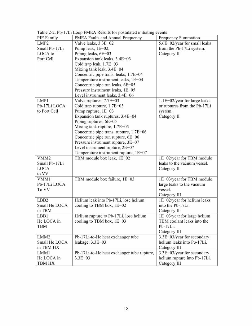
The preliminary FMEA on the Pb-17Li flow loop is given in Appendix A. The main results were not surprising for this single-pass flow loop that cools a small section of the ITER blanket/first wall. Table 2-2 summarizes the PIEs from the FMEA results.
17
From the ITER TBM conference call held on 30 September 2006, the PIE format is four characters:
Character 1 is alphabetic, the type of event, for example L=loss, F=flow, H=heat
Character 2 is alphabetic, the system under consideration, here B=TBM, M=liquid metal, F=first wall
Character 3 is alphabetic, the location of the event, here B=blanket as in TBM breeder module box, V=vessel, P=port cell, M=module flow loop, O=outside, and I=inside
Character 4 is numeric, the accident severity, 1=most severe event, 2=leak, 3=small leak.
18
Table 2-2. Pb-17Li Loop FMEA Results for postulated initiating events PIE Family FMEA Faults and Annual Frequency Frequency Summation LMP2Small Pb-17Li LOCA toPort Cell
Valve leaks, 3.3E 02Pump leak, 1E 02;Piping leaks, 6E 03Expansion tank leaks, 3.4E 03Cold trap leak, 1.7E 03Mixing tank leak, 3.4E 04 Concentric pipe trans. leaks, 1.7E 04Temperature instrument leaks, 1E 04Concentric pipe run leaks, 6E 05Pressure instrument leaks, 1E 05Level instrument leaks, 3.4E 06
5.6E 02/year for small leaks from the Pb-17Li system. Category II
LMP1Pb-17Li LOCA to Port Cell
Valve ruptures, 7.7E 03Cold trap rupture, 1.7E 03 Pump rupture, 1E 03Expansion tank ruptures, 3.4E 04Piping ruptures, 6E 05Mixing tank rupture, 1.7E 05Concentric pipe trans. rupture, 1.7E 06 Concentric pipe run rupture, 6E 06Pressure instrument rupture, 3E 07Level instrument rupture, 2E 07Temperature instrument rupture, 1E 07
1.1E 02/year for large leaks or ruptures from the Pb-17Li system. Category II
VMM2Small Pb-17Li LOCAto VV
TBM module box leak, 1E 02 1E 02/year for TBM module leaks to the vacuum vessel. Category II
VMM1Pb-17Li LOCA To VV
TBM module box failure, 1E 03 1E 03/year for TBM module large leaks to the vacuum vessel.Category III
LBB2Small He LOCA in TBM
Helium leak into Pb-17Li, lose helium cooling to TBM box, 1E 02
1E 02/year for helium leaks into the Pb-17Li. Category II
LBB1He LOCA in TBM
Helium rupture to Pb-17Li, lose helium cooling to TBM box, 1E 03
1E 03/year for large helium TBM coolant leaks into the Pb-17Li.Category III
LMM2Small He LOCA in TBM HX
Pb-17Li-to-He heat exchanger tube leakage, 3.3E 03
3.3E 03/year for secondary helium leaks into Pb-17Li. Category III
LMM1He LOCA in TBM HX
Pb-17Li-to-He heat exchanger tube rupture, 3.3E 03
3.3E 03/year for secondary helium rupture into Pb-17Li. Category III
19
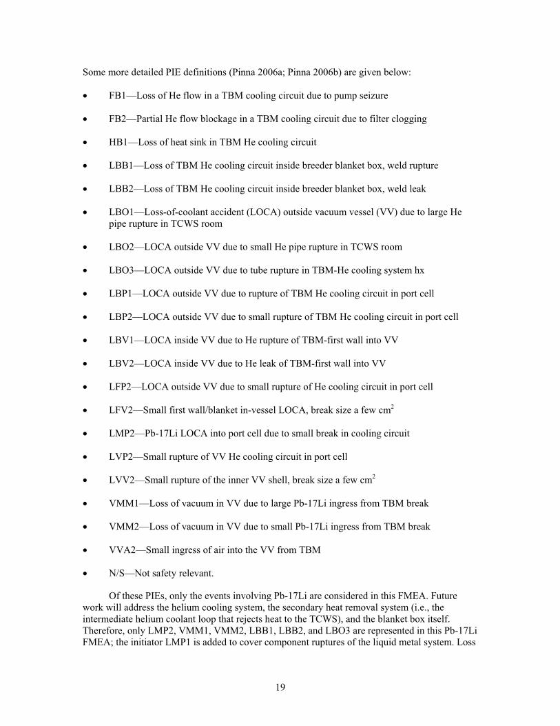
Some more detailed PIE definitions (Pinna 2006a; Pinna 2006b) are given below:
FB1—Loss of He flow in a TBM cooling circuit due to pump seizure
FB2—Partial He flow blockage in a TBM cooling circuit due to filter clogging
HB1—Loss of heat sink in TBM He cooling circuit
LBB1—Loss of TBM He cooling circuit inside breeder blanket box, weld rupture
LBB2—Loss of TBM He cooling circuit inside breeder blanket box, weld leak
LBO1—Loss-of-coolant accident (LOCA) outside vacuum vessel (VV) due to large He pipe rupture in TCWS room
LBO2—LOCA outside VV due to small He pipe rupture in TCWS room
LBO3—LOCA outside VV due to tube rupture in TBM-He cooling system hx
LBP1—LOCA outside VV due to rupture of TBM He cooling circuit in port cell
LBP2—LOCA outside VV due to small rupture of TBM He cooling circuit in port cell
LBV1—LOCA inside VV due to He rupture of TBM-first wall into VV
LBV2—LOCA inside VV due to He leak of TBM-first wall into VV
LFP2—LOCA outside VV due to small rupture of He cooling circuit in port cell
LFV2—Small first wall/blanket in-vessel LOCA, break size a few cm2
LMP2—Pb-17Li LOCA into port cell due to small break in cooling circuit
LVP2—Small rupture of VV He cooling circuit in port cell
LVV2—Small rupture of the inner VV shell, break size a few cm2
VMM1—Loss of vacuum in VV due to large Pb-17Li ingress from TBM break
VMM2—Loss of vacuum in VV due to small Pb-17Li ingress from TBM break
VVA2—Small ingress of air into the VV from TBM
N/S—Not safety relevant.
Of these PIEs, only the events involving Pb-17Li are considered in this FMEA. Future work will address the helium cooling system, the secondary heat removal system (i.e., the intermediate helium coolant loop that rejects heat to the TCWS), and the blanket box itself. Therefore, only LMP2, VMM1, VMM2, LBB1, LBB2, and LBO3 are represented in this Pb-17Li FMEA; the initiator LMP1 is added to cover component ruptures of the liquid metal system. Loss
20
of Pb-17Li flow is not a safety issue. The alloy has a very high boiling point, over 1300°C, and can withstand large amounts of heat without failure.
2.7 Notes from Similar FMEA Studies
Pinna (2006a) discussed an event where a water cooling line to the ITER first wall/blanket leaks or ruptures in the port cell and exposes the helium cooled pebble bed (HCPB) TBM cooling systems to a steam/water spray/humid air environment. The cooling systems to the ITER first wall and divertor are rated at: 125°C, 3 MPa, 140 m3 water per cooling loop (ITER-JCT 2001). Given an in-port LOCA, there are concerns about steam damage in the port cell. The liquid metal coolant piping design calls for electrical heat tracing to prevent coolant solidification and thermal insulation over the heat tracing to protect against heat loss—liquid metals transfer heat rather easily so there must be a fairly thick insulation layer to help retain heat and keep the liquid metal at operating temperature. The insulation will probably be several cm thick, assuming a 40°C outside surface temperature for personnel protection. The steam will likely condense on the insulation and will not transfer much heat away from the Pb-17Li piping. Steam intrusion to the electrical equipment, the pump and valve motors, heater circuits, and instrumentation is likely to be more consequential. However, if the Pb-17Li loop pump experiences a short circuit or other fault due to steam engulfment, the loop flow stagnates. Stagnant Pb-17Li can withstand intense heating (boiling point 1,700°C) and does not pressurize very much, so there is no threat of radiological or hazardous material escape from the loop during 400 s ITER pulses (Wong 2005) unless there is another failure causing loss of loop integrity.
21
2.8 References
ACGIH, 2007. 2007 Guide to Occupational Exposure Values, American Conference of Governmental Industrial Hygienists, Cincinnati, Ohio, 2007.
Agostini, 2004. P. Agostini, E. Baicchi, A. Zucchini, and G. Benamati, “The re-crystallization issue in lead-bismuth technology,” Journal of Nuclear Materials, 335 (2004) 275-279.
APEX, 1999. D.-K. Sze, R. Moir, S. Zinkle, authors of “Chapter 8: Database for Liquid Breeders and Coolants,” in On the Exploration of Innovative Concepts for Fusion Chamber Technology, APEX Interim Report, UCLA-ENG-99-206, November 1999. This report is available at www.fusion.ucla.edu/apex/interim_report.html.
Bagdassarov, 1999. Yu. E. Bagdassarov, I. A. Kuznetsov, A. A. Kamayev, “Comparison of Sodium and Heavy Liquid Metal Fast Reactor Coolants,” Proceedings of the Conference on Heavy Liquid Metal Coolants in Nuclear Technology, October 5-9, 1998, Obninsk, Russian Federation, published by the State Scientific Center of Russian Federation Institute for Physics and Power Engineering, 1999, Volume 2, pages 439-454.
Ballinger, 2004. R. G. Ballinger and J. Lim, “An Overview of Corrosion Issues for the Design and Operation of High-Temperature Lead- and Lead-Bismuth-Cooled Reactor Systems,” Nuclear Technology, 147 (2004) 418-435.
Boisseau, 1982. J. Boisseau, J. Dorey, F. Hedin, C. Le Floch, “Failure Rate Evaluation for Different Components Operating in Sodium, Based on Operating Experience of the Rapsodie and the Phenix Reactors and the Test Loops,” Proceedings of the LMFBR Safety Topical Meeting, presented at Lyon Ecully, France, 19-23 July 1982, published 1982, volume 2, pages 677-686.
Buende, 1991. R. Buende, S. Fabritsiev, and V. Rybin, “Reliability of welds and brazed joints in blankets and its influence on availability,” Fusion Engineering and Design, 16 (1991) 59-72.
Buongiorno, 2004. J. Buongiorno, E. P. Loewen, K. Czerwinski, C. Larson, 2004, “Studies of Polonium Removal from Molten Lead-Bismuth for Lead-Alloy-Cooled Reactor Applications,” Nuclear Technology, 147 (2004) 406-417.
Cadwallader, 1999. L. C. Cadwallader, Liquid Metal, Gas, Molten Salt, and Organic Cooling System Operating Experience Review for Fusion Applications, INEEL/EXT-99-00144, Idaho National Engineering and Environmental Laboratory, February 1999.
Courouau, 2002. J.-L. Courouau et al., “Impurities and oxygen control in lead alloys,” Journal of Nuclear Materials, 301 (2002) 53-59.
Chemical Rubber Company, 1979. Handbook of Chemistry and Physics, 60th edition, Chemical Rubber Company, Boca Raton, Florida, pages D-72 and D-218.
Dostal, 2004. V. Dostal, P. Hejzlar, and N. E. Todreas, “Medium-Power Lead-Alloy Fast Reactor Balance-of-Plant Options,” Nuclear Technology, 147 (2004) 388-405.
22
Drobyshev, 1969. A. V. Drobyshev, V. A. Kurov, and I. T. Filipov, “Some Problems of Operation and Design of Liquid-Metal Loops,” in P. L. Kirillov, V. I. Subbotin, and P. A. Ushakov, editors, Liquid Metals, NASA TT F-522, National Aeronautics and Space Administration Technical Translation series, Washington DC, May 1969.
Argonne National Laboratory, 1991. Experimental Breeder Reactor-II (EBR-II) Level 1 Probabilistic Risk Assessment, Final Draft, EBR-II PRA Revision 2, Argonne National Laboratory, June 1991.
Eide, 1990. S. A. Eide, S. V. Chmielewski, and T. D. Swantz, Generic Component Failure Data Base for Light Water and Liquid Sodium Reactor PRAs, EGG-SSRE-8875, Idaho National Engineering Laboratory, February 1990.
Eide, 1991. S. A. Eide, S. T. Khericha, M. B. Calley, D. A. Johnson, and M. L. Marteeny, Component External Leakage and Rupture Frequency Estimates, EGG-SSRE-9639, Idaho National Engineering Laboratory, November 1991.
Feuerstein, 1988. H. Feuerstein, H. Graebner, and G. Kieser, “TRITEX, a forced convection loop with Pb-17Li,” Journal of Nuclear Materials, 155-157 (1988) 520-523.
Feuerstein, 1991. H. Feuerstein, H. Graebner, J. Oschinski, S. Horn, and S. Bender, “Evaporation of lead and lithium from molten Pb-17Li—Transport of aerosols,” Fusion Engineering and Design, 17 (1991) 203-207.
Feuerstein, 1992. H. Feuerstein, J. Oschinski, and S. Horn, “Behavior of Po-210 in molten Pb-17Li,” Journal of Nuclear Materials, 191-194 (1992) 288-291.
Feuerstein, 1999. H. Feuerstein, S. Horn, and G. Kieser, TRITEX, a ferritic steel loop with Pb-15.8Li, Facility and Operation, FZKA-6286, Forschungszentrum Karlsruhe, May 1999.
Foletti, 2006. C. Foletti, G. Scaddozzo, M. Tarantino, A. Gessi, G. Bertacci, P. Agonstini, and G. Benamati, “ENEA experience in LBE technology,” Journal of Nuclear Materials, 356(2006) 264-272.
Glasbrenner, 2005. H. Glasbrenner, F. Groeschel, H. Grimmer, J. Patorski, M. Rohde, “Expansion of solidified lead bismuth eutectic,” Journal of Nuclear Materials, 343 (2005) 341-348.
Gromov, 1999. B. F. Gromov, O. G. Grigoriev, A. V. Dedoul, G. I. Toshinsky, V. S. Stepanov, and L. B. Nikitin, “The Analysis of Operating Experience of Reactor Installations Using Lead-Bismuth Coolant and Accidents Happened,” Proceedings of the Conference on Heavy Liquid Metal Coolants in Nuclear Technology, October 5-9, 1998, Obninsk, Russian Federation, published by the State Scientific Center of Russian Federation Institute for Physics and Power Engineering, 1999, Volume 1, pages 60-66.
ITER-JCT, 2001. Generic Site Safety Report, Volume VII, “Analysis of Reference Events,” ITER report G 84 r1 6 01-07-10 R 1.0, 2001, page 82.
Hejzlar, 2004. P. Hejzlar, J. Buongiorno, P. E. MacDonald, and N. E. Todreas, “Design Stratgey and Constraints for Medium-Power Lead-Alloy-Cooled Actinide Burners,” NuclearTechnology, 147 (2004) 321-343.
23
Hubberstey, 1992. P. Hubberstey, T. Sample, “Thermodynamic and experimental evaluation of the sensitivity of Pb-17Li breeder blankets to atmospheric contamination,” Journal of Nuclear Materials, 191-194 (1992) 277-282.
IEEE, 1987, IEEE Recommended Practice for the Design and Installation of Electric Heat Tracing Systems for Nuclear Power Generating Systems, American National Standards Institute, ANSI/IEEE Std 622-1987.
Jeppson, 1985. D. W. Jeppson and L. D. Muhlestein, “Safety Considerations of Lithium Lead Alloy as a Fusion Reactor Breeding Material,” Fusion Technology, 8 (1985) 1385-1391.
Jeppson, 1989. D. W. Jeppson, Summary of Lithium-Lead Alloy Safety Compatibility Tests,WHC-EP-0202, Westinghouse Hanford Company, 1989.
King, 1985. R. W. King, “Reliability and Extended Life Potential of EBR-II,” CONF-850713-3, presented at the International Conference on Nuclear Power Plant Aging, Availability Factor, and Reliability Analysis, San Diego, CA, July 8-12, 1985, Argonne National Laboratory, 1985.
Koch, 1988. L. J. Koch, EBR-II, Experimental Breeder Reactor-II, an integrated experimental fast reactor nuclear power station, Argonne National Laboratory, 1988.
Malang, 1995. S. Malang and R. Mattas, “Comparison of lithium and the eutectic lead-lithium alloy, two candidate liquid metal breeder materials for self-cooled blankets,” FusionEngineering and Design, 27 (1995) 399-406.
McIntosh, 1994. A. C. McIntosh, M. Bains, W. Crocombie, and J. F. Griffiths, “Autoignition of Combustible Fluids in Porous Insulation Materials,” Combustion and Flame, 99 (1994) 541-550.
Naus, 2006. D. J. Naus, The Effect of Elevated Temperature on Concrete Materials and Structures – A Literature Review, NUREG/CR-6900, ORNL/TA-2005/553, US Nuclear Regulatory Commission, March 2006, chapter 3.
Pinna, 2006. T. Pinna, Failure Mode and Effect Analysis for the European Helium Cooled Pebble Bed (HCBP) Test Blanket Module, FUS-TN-SA-SE-R-152, draft report, ENEA Frascati, October 2006.
Pinna, 2006a. T. Pinna, Failure Mode and Effect Analysis for the European Helium Cooled Lithium Lead (HCLL) Test Blanket Module, FUS-TN-SA-SE-R-155, draft report, ENEA Frascati, November 2006.
Smith, 1993. M. S. Smith, D. H. Wood, and J. D. Drischler, “An Assessment of Liquid-Metal Centrifugal Pumps at Three Fast Reactors,” Nuclear Technology, 104 (1993) 118-127.
Spencer, 2000. B. W. Spencer, “The Rush to Heavy Liquid Metal Reactor Coolants—Gimmick or Reasoned,” Proceedings of the 8th International Conference on Nuclear Engineering (ICONE), paper 8729, Baltimore, MD, April 2-6, 2000.
24
Walford, 1978. J. G. Walford, “Five Years Experience of the Operation of the Sodium Circuits of the Dounreay Prototype Fast Reactor (PFR),” NUCLEX 78, Construction and Operating Experience with Prototype-Plants of Fast Breeder and High Temperature Gas-Cooled Reactors, INIS-mf-4857V, GB7900116, 1978.
Wong, 2005. C. P. C. Wong, et al., Design Description Document for the U.S. Dual Coolant Pb-17Li (DCLL) Test Blanket Module, report to the ITER Test Blanket Working Group (TBWG), revision 3, GA-C25027, General Atomics, San Diego, CA, November 15, 2005.
25
3. PRELIMINARY FMEA ON U.S. DCLL TBM HELIUM COOLANT LOOP
This FMEA on the TBM helium coolant loop investigated potential accident-initiating events with the TBM helium coolant loops, both the primary coolant to the TBM module box and the secondary helium coolant to the Pb-17Li loop. The helium coolant to the TBM module box is the primary cooling loop for the TBM, removing 54% of the total TBM energy at maximum operating levels. The FMEA results provide insights to the possible accident-initiating events that could occur with the TBM.
3.1 TBM Helium Coolant System Description
As noted in Section 2, helium coolant is used in separate channels from the Pb-17Li breeder-coolant that also cools the TBM module, giving the dual coolant concept. The helium coolant typically removes 54% of the heat from the module via a helium gas heat transfer flow loop and transfers the heat to the TCWS. If the Pb-17Li flow or coolant is lost, the helium can remove enough heat that the TBM can continue to operate without risk of overheat damage, but the reverse is not true—losing helium cooling requires TBM shut down for safety (and ITER shutdown as well). The helium loop has tritium extraction, purification, and heat exchange to the TCWS. The helium loop schematic diagram is given in Figure 3-1. The helium flow loop volume is about 2.3 m3, the flow rate through the TBM piping is about 2 m/s and 8 MPa, and the operating temperatures are 380°C minimum and 460°C maximum. A gas circulator drives the helium through the single-pass flow loop. Piping and components are to be constructed of RAFS and have 10–15 cm of thermal insulation to reduce heat radiation to the test port area.
The main components of the TBM first wall helium cooling loop are a heat exchanger, electrical heater, control valves, and pipework. The electrical heater is turned off during normal operations; it is used to raise the helium to the minimum design temperature. The helium purification system (HPS) is small diameter piping with control valves to control flow. The HPS takes a small fraction of the helium coolant as a bypass flow. The helium purification system removes tritium that might diffuse into the helium coolant. There are no filters in the bypass line (e.g., no dust filters like those used in graphite-moderated Magnox and advanced gas-cooled fission reactors) because there are no recognized sources of dust or other contaminants in the TBM flow loop. It is also noted that the Pb-17Li coolant operates at a maximum of 2 MPa, so if a breach between the helium at 8 MPa and the Pb-17Li occurred within the TBM module then helium would pressurize the liquid metal. The module box is built to withstand such a breach without loss of module integrity (Wong 2005). Any 8 MPa helium breaching into the 2 MPa Pb-17Li will transmit pressure throughout the high temperature (highly fluid) Pb-17Li flow loop quickly, and the noble gas is expected to deposit itself in the headspace of the centrifugal pump casing or its expansion tank. The pressure increase in the Pb-17Li loop could actuate the Pb-17Li rupture disk to the drain tank. If the rupture disk opens, the system will depressurize into the drain tank. It is not clear how the helium system would respond to such a breach—the helium will initially depressurize into the drained Pb-17Li piping, but there is makeup helium available from the pressure control system. With the Pb-17Li drained, the Pb-17Li flow loop would de-energize and present a stagnant branch to the helium flow loop. In theory, the helium pressure control system could re-establish helium pressure and continue to cool the TBM module; however, the effects of the transient on the gas circulator (e.g., low pressure/overspeed trip?) and on the TBM box temperature transient during undercooling may require a shutdown. Otherwise, the helium pressure control system is used when evacuating the helium flow loop in preparation for long outages, for supplying makeup helium, and for system overpressure protection.
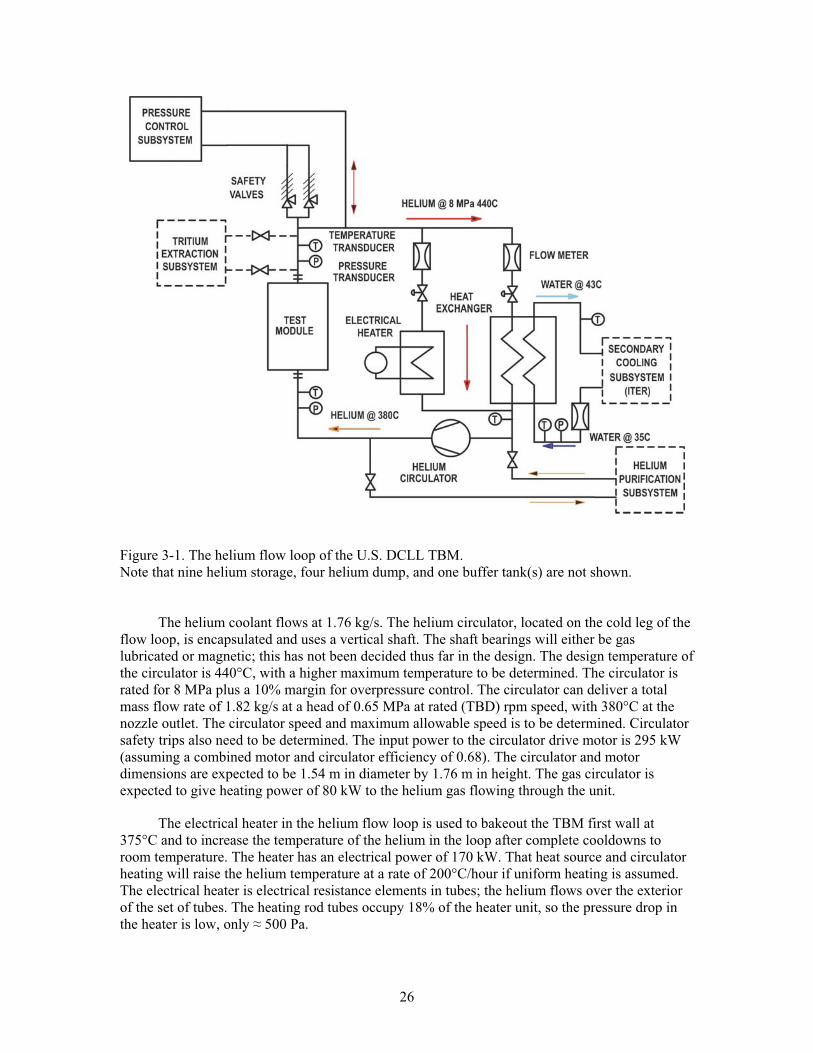
26
Figure 3-1. The helium flow loop of the U.S. DCLL TBM. Note that nine helium storage, four helium dump, and one buffer tank(s) are not shown.
The helium coolant flows at 1.76 kg/s. The helium circulator, located on the cold leg of the flow loop, is encapsulated and uses a vertical shaft. The shaft bearings will either be gas lubricated or magnetic; this has not been decided thus far in the design. The design temperature of the circulator is 440°C, with a higher maximum temperature to be determined. The circulator is rated for 8 MPa plus a 10% margin for overpressure control. The circulator can deliver a total mass flow rate of 1.82 kg/s at a head of 0.65 MPa at rated (TBD) rpm speed, with 380°C at the nozzle outlet. The circulator speed and maximum allowable speed is to be determined. Circulator safety trips also need to be determined. The input power to the circulator drive motor is 295 kW (assuming a combined motor and circulator efficiency of 0.68). The circulator and motor dimensions are expected to be 1.54 m in diameter by 1.76 m in height. The gas circulator is expected to give heating power of 80 kW to the helium gas flowing through the unit.
The electrical heater in the helium flow loop is used to bakeout the TBM first wall at 375°C and to increase the temperature of the helium in the loop after complete cooldowns to room temperature. The heater has an electrical power of 170 kW. That heat source and circulator heating will raise the helium temperature at a rate of 200°C/hour if uniform heating is assumed. The electrical heater is electrical resistance elements in tubes; the helium flows over the exterior of the set of tubes. The heating rod tubes occupy 18% of the heater unit, so the pressure drop in the heater is low, only 500 Pa.
27
The main pipework is 114.3 mm diameter with a wall thickness of 6 mm. The helium flow velocity is between 37.6 and 41.1 m/s. The pipework length has been estimated to be 100 m for the hot leg and 95 m for the cold leg (Table 2.2.2-6 in the DDD gives 180 m [Wong 2005], but the larger values will be used for conservatism in this preliminary FMEA), with two U-bends for thermal expansion control. There are 44 elbows in the pipework, but these are not evident in Figure 3-1. The bypass line to the heater is about 4 m in length and is the same 114.3 mm diameter as the main pipe. The compressed helium volume is 2.3 m3 with a mass of 16.52 kg.
Valves were minimized in the design to preclude friction pressure drop and to avoid inadvertent valve closure, which would mean a loss of flow. One valve is placed before the heat exchanger and one on the bypass to the electrical heater. These valves are position-controlled. The primary helium system has one heat exchanger, one circulator, one electric heater, nine helium storage tanks, four helium dump tanks, and one buffer tank. Despite this knowledge of the equipment available, the HPS and the pressure control system are not designed in detail at this time and are not treated in detail in this preliminary FMEA.
The secondary helium coolant flow loop is called the liquid-breeder-to-helium heat transport loop (LB). The LB removes heat from the Pb-17Li coolant in a heat exchanger and transfers the heat to the TCWS. The LB traverses about 70 m from the TBM to the TCWS vault. The LB helium enters the heat exchanger at 8 MPa and 180°C and exits at 8 MPa and 300°C. That helium travels about 70 m to a water heat exchanger. The water enters at 35°C and exits at 70°C and less than 1 MPa. Because the water heat exchanger is housed in a different room and the helium pressure is much higher than the water pressure, there is no foreseen way to introduce large quantities of water to the helium or liquid metal loops. It is possible that a heat exchanger breach could allow helium to accept some traces of moisture in exchange through a breach location.
3.2 TBM Operation
At the end of the operating day and during outages, the helium cooling system will operate at reduced circulator speed to remove decay heat from the TBM module box. If the level of decay heat is low enough, natural circulation will remove the heat and save circulator operating costs. If the helium loop requires repairs, it is cooled and the helium is evacuated; the piping is then opened to air. Startup after repair requires drawing a vacuum to 100 Pa over 24 hours, then flooding with helium pressurized to 4.5 MPa at 25°C and heating with the electric heater and the gas circulator turning at partial speed continues until the gas reaches 380°C within a few hours. A bakeout session is then conducted at the 380°C temperature with the gas cleanup system operating to remove atmospheric gases and the circulator running up to rated speed. With the temperature at 380°C and the pressure at 8±0.3 MPa, the subsystem is ready for operation.
As a first estimate for operational start/stop demands on the helium flow loop equipment, it is noted that the circulator will operate at reduced speed in a decay heat removal mode for the 14 idle hours on pulse days and it will also continue operating into each ITER maintenance shutdown until the decay heat decreases low enough that forced cooling is not needed. Therefore, there will be four operational start demands per year (not counting any maintenance-related test, or system operability test, starts) for the gas circulator. The TBM helium loop will start up and operate for the 35-day entire pulse campaign, then shut down for any maintenance or other servicing. It is expected that one week into a maintenance outage that the decay heat has reduced enough to no longer require active or natural circulation cooling by the helium loop. Therefore 35 days 24 hr/day 4 campaigns/yr + 7 days cooling/outage 24 hr/day 4 campaign outages/yr) = 4,032 hr/yr. This value is used with the hourly failure rates to give
28
frequency category estimates. For the LB secondary helium cooling loop, the liquid metal does not need to be cooled between pulse days; the assumed mode of operation is to turn the liquid metal pump at reduced speed and slowly circulate the Pb-17Li to keep it in liquid state. Therefore, the LB secondary helium circulator will be turned off each pulse day, so four campaigns per year, 35 days per campaign gives 140 operational starts and stops per year.
As stated previously, the pressure control subsystem is not well defined at this time. There is flow in this system, and the helium flow is cleaned of tritium and particulate. However, the system details are yet to be determined. The pressure control system will not be treated in detail in this preliminary FMEA.
The thermal insulation on the pipe and tank walls is not specified or described well, but the peak insulation surface temperature is given as 68°C (Wong 2005, Table 2.2.2-8). This value suggests that the port room will be an exclusion area for industrial safety reasons as well as radiological reasons because the upper bound surface temperature that humans can accommodate is 40°C without protective equipment (e.g., gloves) (Bernard 1993) and 68°C heat in a 30°C room indicates very short stay times from a personnel heat stress perspective (Bongarra 1985).
3.3 Design Information of Interest
It is noted that Section 841.126 of the American Society of Mechanical Engineers (ASME) gas transmission and distribution piping code B31.8 states that gas velocity should not exceed 100 ft/s (30.5 m/s) at peak conditions and that lower velocity values are recommended for natural gas transmission and distribution (ASME 2003). High gas velocities in piping increase turbulence and pressure drop and high velocity contributes to excessive sound pressure levels (aerodynamic noise), which can cause internal pipe wall erosion. Section 841.125 states that upstream dry gas filters should be considered by designers for rotary or turbine flow meters. Particulates and pipe dust can contaminate meter lube oil and other internal meter components. Section 841.127 states that conical reducers downstream of the pressure regulator or control valve will allow more graded expansion of gas to larger piping and reduce turbulence and pressure drop during gas expansion. The National Fire Protection Association (NFPA), Standard 54, National Fuel Gas Code, states that fuel gases shall have at least schedule 40 piping and shall be welded joints if the system is operating at pressure above 5 psig (NFPA 2006).
Several sources were reviewed to determine if any electrical grounding or bonding were needed for the helium gas system, particularly for reducing any chance of corrosion in the piping due to impurity gases being present in the system. Non-cryogenic gas piping system design does not address bonding or grounding. NFPA 54 states that gas system piping likely to become energized shall be grounded, but this system is not viewed as a metal pipe system that is likely to become electrically energized.
Another point to note is that the U.S. Code of Federal Regulations, 29CFR1910.103, discusses gas system design. Gas system components that could affect personnel safety must be designed to the ASME Boiler & Pressure Vessel Code Section VIII or ASME B31.1 piping code. Shah (2003) noted that these codes do not address all of the materials useful to high-temperature helium design or the highest temperature regimes of operation. Nonetheless, the designers should consider the safety factors specified in these design codes.
29
3.4 Related Operating Experiences Supporting the FMEA
The literature was searched for any helium operating experiences. The most applicable experiences located were those of the helium-cooled fission reactors, even though many of these reactor plants operated many years ago. The first plant discussed is the Dragon Project, a 20 MW-thermal plant in the UK (Gray 1969). The Dragon Project had a helium release design goal of 0.1% of the helium primary coolant inventory per day, based on allowable leakage carrying radioactive products from the fission fuel (e.g., tritium, krypton and xenon isotopes, etc.) rather than cost of helium gas. When the fuel proved to be more leaktight than anticipated, the helium leakage value was judged on cost rather than fission product release. Dragon operating experience demonstrated that they could operate at a leak rate of 0.046%/day, easily remaining within the 0.1%/day value over prolonged operating times. Continuous mass spectrometry of the containment building atmosphere gave early verification of helium leaks and could detect down to 8 grams/hr of helium leakage (0.01%/day). Great care was taken to keep the Dragon helium coolant pure; purging, evacuation, and hot testing helped reduce water and condensable organic compounds. Hygrometers measured water vapor and hydrogen, while gas chromatographs measured other gas concentrations in volume parts per million (vppm). Typical impurities were: CO—1 vppm, CO2—0.5 vppm, H2O—0.5 vppm, H2—1.5 vppm, and CH4—1 vppm. Some of these impurities arose due to fission fuel and graphite, but water vapor is certainly an issue for the TBM to address. The purification system generally acted rapidly to reduce impurities. The purification system had a total cleanup time constant of 0.66/hr. Some of the Dragon valves showed sticking behavior of metal-metal seats when they were opened after remaining closed for long periods of time. The valves exhibiting sticking phenomena were modified so the motor operators would deliver a shock when opening to break the metal-metal contact and there were no problems afterward. There were 250 motor-operated valves in the helium purification systems, but only one failed (and required replacement) in 3 years of plant operations. (Note: this is a 1.5E 07/hour ‘failure to operate’ failure rate for these valves.) The helium circulators operated well; only one 100-hp unit suffered a gas bearing failure in an aggregate 180,000 operating hours. Three of the six 100-hp circulators were overhauled (stripped and rebalanced) in the first 3 years; loose contamination was slight and easily swabbed. The helium to water heat exchangers suffered some tube leaks that were severe enough to prompt replacement of all six heat exchangers after 3 years of operation. The dose rates generated by fission products (Cr-51, Mn-54, Fe-59, etc.) at 1 ft from the heat exchangers were 32 mrem/hr gamma and 30 mrem/hr beta, and the entire job of six units being replaced spanned 30 days. Gray also noted that Dragon helium coolant had “non-ideality,” meaning that the ideal gas equation prediction was higher than the actual helium density. At 100 atmospheres pressure the helium density was 10% below the ideal gas density, and at the operating pressure of 20 atmospheres the helium density was 1% below ideal gas density. The Dragon also had three purification systems: one for the primary helium coolant, one for gas flow purge directly from the fuel, and one spare system.
The Peach Bottom Unit 1 reactor, a 115 MW-thermal plant, also reported some operating experiences. The piping and gas circulators worked well, but the helium-to-water superheat steam generator tubes suffered from chloride stress corrosion cracking. Hygrometers were used on the helium system to sense moisture intrusion. The main source of moisture was from steam generator tube leakage. Electrolytic hygrometers were used, but these units had short functional life spans that necessitated frequent changeouts, so personnel maintenance time and personnel radiological exposure were both large for these monitors. The plant staff recommended infrared or optical detectors rather than electrolytic units.
It is noted that the Dragon reactor, Peach Bottom, and the Arbeitsgemeinschaft Versuchreaktor (AVR) (the working group research reactor) plant all described their system leak
30
rates. Gray (1969) stated that the 20 MW Dragon reactor had a design goal leak rate of 0.1% of the primary system helium inventory per day at the operating pressure of 20 atmospheres. In practice, Capp (1976) stated that the actual leak rate could reach about 0.12% per day (about 0.2 kg/day from the 180 kg helium inventory in the primary system [Capp 1976]). Another 1 kg was taken from the Dragon reactor per day to sample the helium for various activated products and impurities. Green (1969) stated that the 115 MW Peach Bottom plant operated at about 23 atmospheres and had a design leak rate goal of 0.09 kg/day (this was probably a 0.01% leak rate per day for a 900 kg-helium inventory) but in actuality leaked up to 2.7 kg/day or 0.3%/day. Cautius (1969) stated that the 46 MW-thermal AVR plant operated at 10.8 atmospheres, and leaked on average one complete helium charge (one primary coolant inventory) of 4,000 cubic meters STP ( 715 kg helium) per year. That is a leak rate of 0.27% or 1.96 kg per day. Shaft penetrations were an issue, and flanges that had to be opened and resealed were another issue.
The Fort St. Vrain plant was a large helium-cooled reactor of 824 MW and 330 MW-electric, this plant had a technical specification overall allowable leak rate of 880 kg/day. Metallic pressure boundaries in the concrete vessel did not leak, but valve shaft seals gave more than their allocated allowable leak rate. The conventional valve stem packing was replaced with Teflon and metal rings that lowered the leak rate to less than the allocated allowable value. The reciprocating piston helium compressors had major maintenance problems despite design for helium service (Simon 1992). Additionally, Fort St. Vrain had trouble with moisture monitors that required frequent maintenance. Fort St. Vrain also had a few other operating experience suggestions, namely, to use copper oxide beds instead of titanium sponge beds for hydrogen removal from the helium and to use magnetic bearings rather than water-cooled bearings in gas circulators—this would make auxiliary systems to gas circulators simpler (auxiliaries were high failure rate items at this plant) and prevent moisture ingress into the helium coolant (Fuller 1989). Copinger (2004) had some other operating experience data on Fort St. Vrain. The helium purification system must have good moisture removal or the moisture will freeze and plug the cold charcoal beds that capture noble gases. Perhaps ITER TBM coolant will not have any concern about noble gas cleansing, but moisture in a system is problematic for corrosion as well as plugging cryogenic purification units. Other issues with Fort St. Vrain included moisture intrusion from water-cooled bearings on the gas circulators. This must be precluded in the TBM design, perhaps by using either gas-cooled or magnetic bearings.
The High Temperature Engineering Test Reactor (HTTR) in Japan is a helium-cooled high temperature (850 to 950°C) reactor presently in operation. This reactor has set goals for helium coolant purity (Sakaba 2004) during operation:
Impurity Concentration (ppm) Hydrogen 3 Carbon monoxide 3 Water vapor 0.2 Carbon dioxide 0.6 Methane 0.5 Nitrogen 0.2 Oxygen 0.04
The HTTR uses a pre-charcoal trap, an inlet heater, two copper oxide fixed beds, gas coolers, two molecular sieve traps, two cold charcoal traps, and small gas circulators to cleanse the helium gas. Dual units provide the ability to regenerate or service equipment while the system remains on line. The purification system has a 200 kg/h flow rate and processes >10% of the
31
primary coolant inventory each hour. The copper oxide catalyst bed oxidizes hydrogen to water vapor and carbon monoxide to carbon dioxide. The molecular sieve traps water vapor and carbon dioxide. The cold charcoal trap at 195°C adsorbs oxygen and nitrogen (i.e., air), methane, and noble gases. The charcoal trap only flows 50 kg/h and bypasses the rest of the helium gas in the purification flow stream. The HTTR has concerns for fission product noble gases (krypton and xenon); these are held on the cold trap for about 50 days and then are sent to the gaseous radwaste treatment system. The HTTR removed about 0.75 kg of water from the primary system during commissioning tests. Most of the initial impurities were traced to the graphite in the fission reactor core, the heat insulator in the gas duct, and original impurities in the helium gas supply. The HTTR helium coolant is supplied from gas storage tanks. It is noted that other gas-cooled reactors (e.g., the carbon dioxide-cooled Magnox and Advanced Gas Reactor plants) used cryogenic gas supply for enhanced gas purity (Poulter 1963).
3.5 FMEA Failure Rate Data
There is no database, similar to the liquid metal CREDO database, for gas components and no compilation of component failure rate data from past helium-cooled fission reactors such as the Peach Bottom and Fort St. Vrain units, nor from the German AVR and Thorium High Ttemperature Reactor (THTR) plants. The newest plants, the Japanese HTTR and Chinese HTR-10, have only operated for about 4 to 8 years—that amount of time may not be adequate to give matured failure rates for small numbers of components in these small reactor plants. The Helium Loop Karlsruhe (HELOKA) is planned to test helium cooling loops and generate reliability data for ITER TBM usage (Ghidersa 2006). At present, the component failure rate data used in this FMEA came from several sources on gas system components. Some data arose from non-nuclear gas applications and some data came from gas systems in use in nuclear and radiological facilities at the Savannah River Site in the U.S. The best available data were used, but these data are generic and are in no way specific to the TBM application. The data sources used here included some sparse helium-cooled and carbon dioxide-cooled fission reactor data (Hannaman 1978), compressed gas system data (Blanton 1993), and some inferred data were taken from water reactor data reports (NUREG 2007). While these coolants are dissimilar, the water-cooled fission reactors do have a wide body of data to draw from. There are a few helium component data values reported in the literature (for example, Bittermann 1977; Solomon 1975) but these are scattered data of unknown origin; the data may or may not come from helium system operating experiences. Component sizes vary widely from the small TBM to the larger power plant scale, but given the sparse data the values were applied to the smaller equipment. The data cited in the preliminary FMEA tables are considered to be the most representative data available at this time to apply to TBM components. Data verification efforts are described below.
To test validity of the data cited in the FMEA, a literature review was performed to identify any gas system component failure rate data generated by operating experiences. One of the most recent documents (Chamberlin 2005) described that compressed natural gas-specific hardware failure rate data would be needed for more detailed quantitative work; for their task the authors used military and chemical industry published data and compiled natural gas vehicle fleet operations experience data to quantify their fire risk fault trees and event trees. Their statement indicates that there is not a recognized source gas system component failure rates. Data from gas system operating experiences were sought in the literature; few reports were found. The author believes the sparse number of data sets is due to the lack of a regulatory mandate to collect and analyze the data. If companies collect data for their own purposes (such as - maintenance planning, spare parts procurement, facility life cycle planning, etc.), then these data are not reaching publication. Some literature that suggested great promise of failure rate data was actually tutorial in nature and contained no data (Wilcox 2001) or the data was expert judgment
32
used to determine overall system function, and was not experience-based failure rate data (Deleris 2006). Of the few studies actual failure rate data, two were from Nederlandse Gasunie (Bosman 1985; Lammerse 1985) the Holland natural gas distribution and retail sales company, and two were from Italgas data sets (Piccininni 1988; Scarrone 1989). The components used in natural gas distribution are much, much larger than those in the TBM flow loop, and distribution piping has the additional environment concerns of weather (lightning, wind, ice, etc.), buried pipe corrosion and strikes from unauthorized digging or above-ground pipe concerns of vehicle impact and weather. Bosman gave a mean time to failure (MTTF) of 400 hours (or, 2.5E 03/h) for four large, de Laval reciprocating piston compressors, and he cited instrument, valve, and electrical component failure rates from the UK Atomic Energy Authority data sets from nuclear fission reactor operating experience data. Lammerse gave some data on a larger set of thirteen compressors, MTTF=680.42 h (or, 1.5E 03/h) and a mean time to repair of 6.7 h. Shut-off valves for impulse lines were 2.4E 05/h and gas control valves were 2.7E 05/h as “all modes” failure rates. Temperature sensor-transmitter units were 8E 06/h and pressure transmitters were 2.5E 05/h. These values are all greater than the values used in the FMEA tables in the appendix. This discrepancy is believed to be due to two main reasons. First, the Gasunie data is for much larger equipment in a more harsh environment, and sometimes the component designs are very different. Second, the Gasunie data values were reported for “all modes,” so decomposition of the values into specific failure modes like those cited in the FMEA would bring the Gasunie data closer to agreement with the values used in the FMEA. The Italgas data was detailed, but treated many components important to gas sales but not used in the TBM gas flow loop—gas pressure regulators (not addressed yet in TBM design), gas monitoring regulators, ‘slam-shut’ isolation valves, diaphragm vent valves, gas filters, and water intrusion concerns. These data were in the 1E 05 to 1E 07/h range for overall, “all modes” failure rates. The range of data values from the Italgas tables are in cursory agreement with the failure rates in the FMEA table in Appendix B.
Other gas system reliability data was sought. Labath (1986) used nuclear and general chemical industry data to quantify fault trees for a hydrogen sulfide storage plant, as did a 1980’s landmark risk study of industrial plants (Risk 1982). Medhekar (1993) used a nuclear plant piping reliability prediction method to apply to liquid and gas products in chemical plants. Simion (1993) evaluated hydrogen cooling systems for generators in nuclear power plants, but used operations experience to give a hydrogen leak frequency with fire or explosion of 6E 03/plant-year rather than model the pipework and cooling system components. More recently, Nelson (2007) used a combination of chemical industry and gas reactor-light water reactor data to quantify a hydrogen production plant risk assessment. Given these findings—the sparse data available is a fair comparison to the data used and that several studies have used nuclear power plant data to apply to gas systems, the data used are considered to be reasonable values at present. When more design information on TBM gas loop components is known the data will be revisited and vendors can also be asked to provide data rather than rely on generic data from handbooks and large plant operating experiences.
An important failure rate for this flow loop was the helium circulator failure to operate. It is recognized that the UK has the most experience with gas movers since they have operated a fleet of carbon dioxide-cooled fission reactors for decades. However, no recent information on gas circulator reliability was found in a literature search. An older paper by Cave (1977) gave some data about Magnox gas circulators (axial flow turbomachine units, vertical or horizontal, oil or gas cooled bearings, either steam turbine- or electric motor-driven). These units are large, in the 200 to 500 kg/s flow range at 6 to 20 atmospheres pressure. The TBM unit is smaller, less flow (maximum of 1.82 kg/s) and higher pressure—but these fission experiences are the most applicable to estimate reliability of the TBM circulator. Cave (1977) gave 35 individual, electric-driven circulator failures to run at the Berkeley, Bradwell, Hinkley Point A, Trawsfynydd, and
33
Sizewell Magnox and Advanced Gas Reactor (AGR) plants. There are 8 gas circulators per reactor (Loftness 1964) and the combined reactor operating time of 117 reactor-years gave 936 circulator-years, or a failure to operate of 3.7E 02/circulator-year. For these plants at that time, a reactor year was 75% of a calendar year or 6,600 h/year (Dixon 1974). Therefore a failure rate of 3.7E 02/circulator-year gave 5.6E 06 failures to run per circulator-hour. It is noted that most of these Magnox plants had two circulators per cooling circuit, so the loss of one unit was not a ‘scram’ event at most of these fission reactors if the operator could halt reverse gas flow after a circulator outage. There were no common cause failures in these reported failure events. As a comparison, the Japanese HTTR helium cooled fission test reactor had first criticality on November 10, 1998, but has not operated for full calendar years since then. The HTTR has 4 vertical gas circulators, three in the primary coolant system that flow at about 3 kg/s at 4 MPa, 2,000 to 12,000 rpm, and another circulator is in the intermediate cooling loop. These units use gas bearings (Furusawa 2004). Recall that the TBM circulator is 1.76 kg/s at 8 MPa. Data on HTTR circulator operating experience has not been found in the literature. One internet source noted a trip of one primary gas circulator on May 16, 2003 during plant startup (JAERI 2005). An electric part failed, it was replaced. Electric power parts are outside the component boundary of the circulator; that is, the circulator component itself is not accountable for failing to run if it lost electrical motive power. Assuming no failures of these four units (since no failures have been reported or described in the technical literature) and 25% availability of the HTTR (over 8 years of operations) in its lifetime (see JAERI 2002 for an HTTR schedule) gives an average, or 50%, failure rate calculation of = 2(50%,2dof)/2T, where ‘dof’ is degrees of freedom for the chi-squared distribution and T is the accumulated operating hours (equation from IAEA 1992). For zero failures (dof=2) the 50% chi-squared distribution tabulation is 1.39, and the denominator is 2[(8 years)(8760 h/y)(0.25 available)(4 units)]. Making the calculation, the average failure rate from these assumed data is 9.9E 06/hour, which is a factor of 1.8 greater than the 117 reactor-year Magnox value. The short operating time HTTR value is reasonably close to the larger population Magnox value, if the reader uses the definition of failure rate good agreement being within a half-order of magnitude ( 10, or a factor of 3.16). With this good agreement, a judgment is made to use the data with the most experience, since it is expected that as HTTR operates longer the circulator failure rate would decrease. Therefore, the TBM gas circulator ‘failure to operate’ failure rate is 5.6E 06/h. The TBM helium circulator failing to run would be 1.7E 02/year, which is a Category II event. This is a somewhat high frequency considering the consequences of loss of TBM helium flow. The TBM designers can either specify a highly reliable circulator that undergoes extensive testing and overhaul, or add a second, independent 100%-flow unit to increase gas flow reliability. A few of the notable gas circulator events on Magnox reactors have been Rizk (1965) where a diffuser channel shell had failed due to fatigue cracking caused by an acoustic-aerodynamic forces. The higher harmonics of blade passing frequency gave excitation to circulator parts, fatiguing the diffusers and spokes. The circulators were redesigned with inlet vanes, flow straighteners, and diffuser channel supports. Gould (1987) discussed that a thrust bearing on a horizontal shaft, axial flow gas circulator at the Oldbury plant failed. The failed bearing allowed the circulator’s rotating assembly moved back until the impeller made contact with the circulator diffuser and casing. The impeller rubbed severely before the circulator stopped rotating. The failure occurred in May 1983 and required replacement of the gas circulator unit. The Oldbury plant returned to operation in October 1984—investigations, lead time to purchase a new unit, and repair/replacement activities required more than a year. As a comparison, the actual replacement activity took 45 days when the Fort St. Vrain plant replaced a helium circulator (Simon 1992).
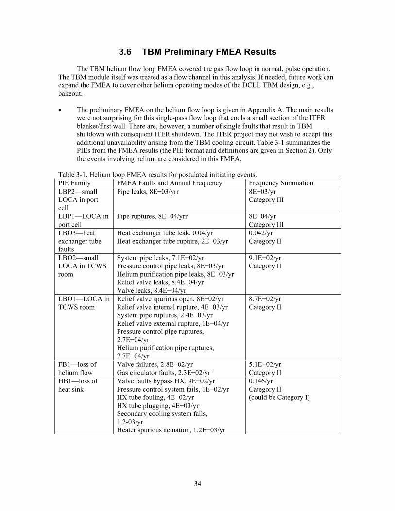
34
3.6 TBM Preliminary FMEA Results
The TBM helium flow loop FMEA covered the gas flow loop in normal, pulse operation. The TBM module itself was treated as a flow channel in this analysis. If needed, future work can expand the FMEA to cover other helium operating modes of the DCLL TBM design, e.g., bakeout.
The preliminary FMEA on the helium flow loop is given in Appendix A. The main results were not surprising for this single-pass flow loop that cools a small section of the ITER blanket/first wall. There are, however, a number of single faults that result in TBM shutdown with consequent ITER shutdown. The ITER project may not wish to accept this additional unavailability arising from the TBM cooling circuit. Table 3-1 summarizes the PIEs from the FMEA results (the PIE format and definitions are given in Section 2). Only the events involving helium are considered in this FMEA.
Table 3-1. Helium loop FMEA results for postulated initiating events. PIE Family FMEA Faults and Annual Frequency Frequency Summation LBP2—smallLOCA in port cell
Pipe leaks, 8E 03/yrr 8E 03/yr Category III
LBP1—LOCA in port cell
Pipe ruptures, 8E 04/yrr 8E 04/yr Category III
LBO3—heatexchanger tube faults
Heat exchanger tube leak, 0.04/yr Heat exchanger tube rupture, 2E 03/yr
0.042/yr Category II
LBO2—small LOCA in TCWS room
System pipe leaks, 7.1E 02/yr Pressure control pipe leaks, 8E 03/yr Helium purification pipe leaks, 8E 03/yr Relief valve leaks, 8.4E 04/yr Valve leaks, 8.4E 04/yr
9.1E 02/yr Category II
LBO1—LOCA in TCWS room
Relief valve spurious open, 8E 02/yr Relief valve internal rupture, 4E 03/yr System pipe ruptures, 2.4E 03/yr Relief valve external rupture, 1E 04/yr Pressure control pipe ruptures, 2.7E 04/yr Helium purification pipe ruptures, 2.7E 04/yr
8.7E 02/yr Category II
FB1—loss of helium flow
Valve failures, 2.8E 02/yr Gas circulator faults, 2.3E 02/yr
5.1E 02/yr Category II
HB1—loss of heat sink
Valve faults bypass HX, 9E 02/yr Pressure control system fails, 1E 02/yr HX tube fouling, 4E 02/yr HX tube plugging, 4E 03/yr Secondary cooling system fails, 1.2-03/yr Heater spurious actuation, 1.2E 03/yr
0.146/yr Category II (could be Category I)
35
3.7 Notes from Similar FMEA Studies
Pinna (2006) discussed an event where a water cooling line to the ITER first wall/blanket leaks or ruptures in the port cell and exposes the HCPB TBM cooling systems to a steam/water spray/humid air environment. The cooling systems to the ITER first wall and divertor are rated at: 125°C, 3 MPa, 140 m3 water per cooling loop (GSSR 2001). Given an in-port LOCA, there are concerns about steam damage in the port cell. The outer surface of the insulation on the helium piping will be 68°C, which is about half the temperature of the intruding steam. Heat transfer is expected to be slow through the pipe and tank insulation to the steam in the room. The effects of steam engulfment of motor-operated valves and the circulator motor are unknown. Certainly this equipment will be required to be operable in harsh environments (such as steam atmospheres) so that the TBM can be safely shut down in case of emergencies.
3.8 Conclusions
The helium coolant is the primary cooling system for the DCLL TBM. This preliminary FMEA has shown that there are many single-component faults that will cause the cooling system to give degraded or no cooling performance, thus requiring ITER to shut down to repair the TBM helium cooling loop. Such forced outages may not be tolerable from the ITER operations point of view, since the operators will be striving to maximize machine availability. Also, the frequencies of events are high. This is believed to be due to two factors, assumptions on piping lengths (assumed 600 m of piping in the helium pressure control and helium purification systems) and the existing component failure rate data. Even with overestimates of pipe length that could be a factor of 3 greater than actual, the resulting frequency Categories would not change. Regarding the failure rate values, the best data sources available were used and applied to this intermediate size system. The cooling system is not large like a power plant, and not small like a laboratory experiment, so the data values may not accurately represent the TBM components. Another factor is that the data sources used did not originate from helium system operating experiences. Certainly most of the helium-cooled power plants (AVR, THTR, HTTR, Peach Bottom) have operated better than these data values would indicate, but no data compilations are available from those fission experiences. The failure rate data used were compared to published natural gas distribution equipment failure rates. The component failure rate values used here were lower than those data, so the results are considered to be reasonable for present purposes.
Based on existing FMEA results, many individual component faults in the helium cooling system will cause the system to stop operating; many of the failures are so-called ‘single failures’ that will result in taking the TBM off-line and consequently taking ITER off-line. These faults do not necessarily result in radiological releases, but they do impact ITER availability. Based on these results, design consideration should be given to overdesigning some components to be as robust (highly reliable) as possible, performing rigorous maintenance schedules and post-maintenance tests, and considering use of redundant equipment for some components, e.g., gas circulator.
36
3.9 References
ASME, 2003. Gas Transmission and Distribution Piping Systems, Code B31.8-2003.
Bernard, 1993. R. E. Bernard and M. F. Foley, “Upper acceptable surface temperature for prolonged hand contact,” International Journal of Industrial Ergonomics, 11 (1993) 29-36.
Bittermann, 1977. D. Bittermann, J. Wehling, “Reliability Analysis of the Decay Heat Removal Systems of a 1000-MW(e) Gas-Cooled Fast Breeder Reactor,” Nuclear Technology, 32(1977) 247-256.
Blanton, 1993. C. H. Blanton and S. A. Eide, Savannah River Site Generic Data Base Development, WSRC-TR-93-262, Westinghouse Savannah River Company, Aiken, SC, June 30, 1993.
Bongarra, 1985. J. P. Bongarra, Jr. et al., Human Factors Design Guidelines for Maintainability of Department of Energy Nuclear Facilities, UCRL-15673, Lawrence Livermore National Laboratory, June 1985, section 3.2.4.5.
Bosman, 1985. M. Bosman, “Availability Analysis of a Natural Gas Compressor Plant,” Reliability Engineering, 11 (1985) 13-26.
Capp, 1976. P. D. Capp and R. A. Simon, “Operational Experience with the Dragon Reactor Experiment of Relevance to Commercial Reactors,” paper IAEA-SM-200/19, in Gas-Cooled Reactors with Emphasis on Advanced Systems, IAEA, Vienna, 1976, pages 95-115.
Cautius, 1969. W. Cautius, H. J. Hantke, G. Ivens, and F. Schweiger, “Operational Experience with the AVR Reactor,” paper IAEA-SM-111/20, in Advanced and High-Temperature Gas-Cooled Reactors, IAEA, Vienna, 1969, pages 37-50.
Chamberlin, 2005. S. Chamberlin and M. Modarres, “Compressed Natural Gas Bus Safety: A Quantitative Risk Assessment,” Risk Analysis, 25 (2005) 377-387.
Copinger, 2004. D. A. Copinger and D. L. Moses, Fort Saint Vrain Gas Cooled Reactor Operational Experience, NUREG/CR-6839, U.S. Nuclear Regulatory Commission, January 2004.
Deleris, 2006. L. A. Deleris, G. L. Yeo, A. Seiver, M. E. Pate-Cornell, “Engineering Risk Analysis of a Hospital Oxygen Supply System,” Medical Decision Making, 26 (2006) 162-172.
Dixon, 1974. F. Dixon and H. K. Simons, “The Central Electricity Generating Board’s nuclear power stations: a review of the first 10 years of Magnox reactor plant performance and reliability,” British Nuclear Energy Society Journal, 13 (1974) 9-38.
FMD-97, 1997. Failure Mode/Mechanism Distributions, 1997, FMD-97, Reliability Analysis Center, Rome Laboratory, Rome, New York, December 1997, pages 2-236 to 2-237.
Fuller, 1989. C. H. Fuller, “Fort Saint Vrain Operational Experience,” Technical Committee Meeting on Design Requirements, Operation and Maintenance of Gas-Cooled Reactors,San Diego, CA, September 21-23, 1988, published by the International Atomic Energy
37
Agency International Working Group on Gas-Cooled Reactors, IWGGCR-19, IAEA, Vienna, Austria, 1989, pages 55-61.
Furusawa, 2004. T. Furusawa, M. Shinozaki, S. Hamamoto, Y. Oota, “Cooling system design and structural integrity evaluation,” Nuclear Engineering and Design, 233 (2004) 113-124.
Ghidersa, 2006. B. E. Ghidersa, M. Ionescu-Bujor, and G. Janeschitz, “Helium Loop Karlsruhe (HELOKA): A valuable tool for testing and qualifying ITER components and their He cooling circuits,” Fusion Engineering and Design, 81 (2006) 1471-1476.
Gould, 1987. A. W. Gould, “Gas circulator repairs,” Proceedings of the Institution of Mechanical Engineers, 201A (1987) 215-222.
Gray, 1969. P. S. Gray and C. Watts, “Operating Experience with the Dragon Reactor,” paper SM-111/66, in Advanced and High-Temperature Gas-Cooled Reactors, IAEA, Vienna, 1969, pages 3-19.
Green, 1969. R. W. Green and J. S. Kemper, “Significant Operating Experiences of the Peach Bottom Atomic Power Station,” paper SM-111/74, in Advanced and High-Temperature Gas-Cooled Reactors, IAEA, Vienna, 1969, pages 21-36.
GSSR, 2001. Generic Site Safety Report, Volume VII, “Analysis of Reference Events,” ITER report G 84 r1 6 01-07-10 R 1.0, 2001, page 82.
Hannaman, 1978. G. W. Hannaman, GCR Reliability Data Bank Status Report, GA-A14839, General Atomic Company, San Diego, CA, July 1978.
IAEA, 1992. Manual on reliability data collection for research reactor PSAs, IAEA-TECDOC-636, International Atomic Energy Agency, January 1992, chapter 9.
JAERI, 2002. Press Release “The HTTR Passes Pre-Operation Inspection,” at the web site http://www.jaeri.go.jp/english/press/2002.html, Figure 3, ‘Overall schedule of the HTTR project’, visited March 12, 2007.
JAERI, 2005. Japan Atomic Energy Research Institute Annual Report: April 2004-May 2004,section 3 research on High Temperature Engineering, at the web site http://www.jaeri.go.jp/english/annual/2003e/html/chap03.html, visited March 12, 2007.
Labath, 1986. N. A. Labath, M. C. Real, A. J. Huespe, and M. J. Masera, “A Safety and Risk Assessment of a Hydrogen Sulphide Storage Plant Sited at the Boundary of a Nuclear Power Plant,” Reliability Engineering, 14 (1986) 223-243.
Lammerse, 1985. H. Lammerse and M. Bosman, “Data of Gas Compressors and Instrumentation—Hard to Collect, Easy to Analyse,” Reliability Engineering, 13 (1985) 65-78.
Loftness, 1964. R. L. Loftness, Nuclear Power Plants: design, operating experience and economics, Van Nostrand Reinhold, New York, 1964, chapter 6.

38
Medhekar, 1993. S. R. Medhekar, D. C. Bley, and W. C. Gekler, “Prediction of Vessel and Piping Failure Rates in Chemical Process Plants Using the Thomas Model,” Process Safety Progress, 12 (1993) 123-126.
Nelson, 2007. P. F. Nelson, A. Flores, and J. L. Francois, “A design-phase PSA of a nuclear-powered hydrogen plant,” Nuclear Engineering and Design, 237 (2007) 219-229.
NFPA, 2006. National Fuel Gas Code, Standard 54, US National Fire Protection Association, Qunicy, MA.
NUREG, 2007. Industry-Average Performance for Components and Initiating Events at U.S. Nuclear Power Plants, NUREG/CR-6928, U.S. Nuclear Regulatory Commission, February 2007.
Piccinini, 1989. N. Piccinini and M. Scarrone, “Availability of a Pressure Regulating Installation on a City Mains,” Reliability Engineering and System Safety, 20 (1989) 303-321.
Pinna, 2006. T. Pinna, Failure Mode and Effect Analysis for the European Helium Cooled Pebble Bed (HCBP) Test Blanket Module, FUS-TN-SA-SE-R-152, draft report, ENEA Frascati, October 2006.
Pinna, 2006a. T. Pinna, Failure Mode and Effect Analysis for the European Helium Cooled Lithium Lead (HCLL) Test Blanket Module, FUS-TN-SA-SE-R-155, draft report, ENEA Frascati, November 2006.
Poulter, 1963. D. R. Poulter, The Design of Gas-Cooled Graphite-Moderated Reactors, Oxford University Press, New York, 1963, chapter 8.
Risk, 1982. Risk Analysis of Six Potentially Hazardous Industrial Objects in the Rijnmond Area, a Pilot Study, a Report to the Rijnmond Public Authority, D. Reidel Publishing Company, Dordrecht, Holland, 1982, appendix IX.
Rizk, 1965. W. Rizk and D. F. Seymour, “Investigations into the Gas Circulator Failures at Hinkley Point,” Nuclear Engineering, 10 (May 1965) 180-181.
Sakaba, 2004. N. Sakaba, T. Furusawa, T. Kawamoto, Y. Ishii, Y. Oota, “Short descriptions of other systems of the HTTR,” Nuclear Engineering and Design, 233 (2004) 147-154.
Scarrone, 1989. M. Scarrone, N. Piccinini and C. Massobrio, “A reliability data bank for the natural gas distribution industry,” Journal of Loss Prevention in the Process Industries, 2(1989) 235-239.
Shah, 2003. V. N. Shah, S. Majumdar, and K. Natesan, Review and Assessment of Codes and Procedures for HTGR Components, NUREG/CR-6816, U.S. Nuclear Regulatory Commission, Washington, DC, June 2003.
Simion, 1993. G. P. Simion, R. L. Van Horn, C. L. Smith, K. D. Bulmahn, J. H. Bickel, and M. B. Sattison, Risk Analysis of Highly Combustible Gas Storage, Supply, and Distribution Systems in PWR Plants, NUREG/CR-5759, U.S. Nuclear Regulatory Commission, June 1993, page 38.
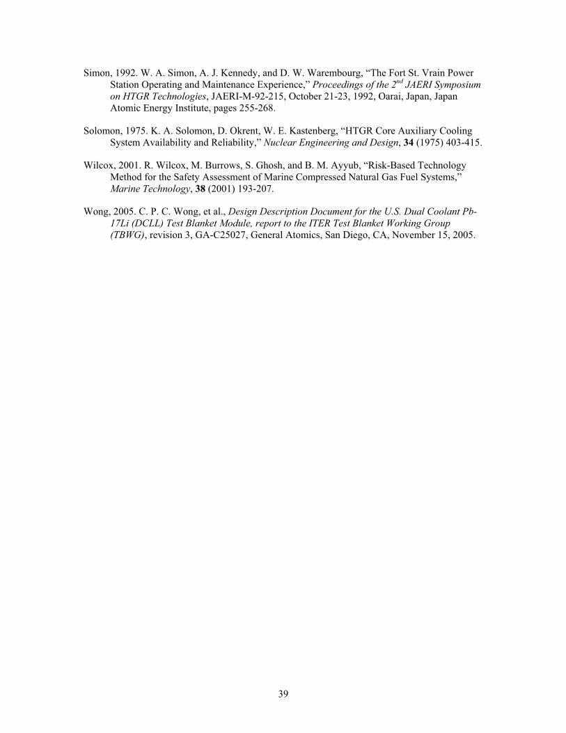
39
Simon, 1992. W. A. Simon, A. J. Kennedy, and D. W. Warembourg, “The Fort St. Vrain Power Station Operating and Maintenance Experience,” Proceedings of the 2nd JAERI Symposium on HTGR Technologies, JAERI-M-92-215, October 21-23, 1992, Oarai, Japan, Japan Atomic Energy Institute, pages 255-268.
Solomon, 1975. K. A. Solomon, D. Okrent, W. E. Kastenberg, “HTGR Core Auxiliary Cooling System Availability and Reliability,” Nuclear Engineering and Design, 34 (1975) 403-415.
Wilcox, 2001. R. Wilcox, M. Burrows, S. Ghosh, and B. M. Ayyub, “Risk-Based Technology Method for the Safety Assessment of Marine Compressed Natural Gas Fuel Systems,” Marine Technology, 38 (2001) 193-207.
Wong, 2005. C. P. C. Wong, et al., Design Description Document for the U.S. Dual Coolant Pb-17Li (DCLL) Test Blanket Module, report to the ITER Test Blanket Working Group (TBWG), revision 3, GA-C25027, General Atomics, San Diego, CA, November 15, 2005.
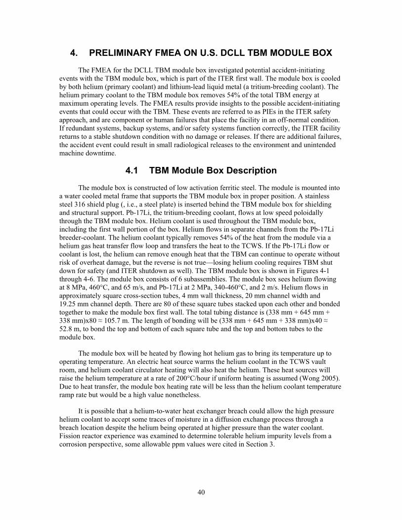
40
4. PRELIMINARY FMEA ON U.S. DCLL TBM MODULE BOX
The FMEA for the DCLL TBM module box investigated potential accident-initiating events with the TBM module box, which is part of the ITER first wall. The module box is cooled by both helium (primary coolant) and lithium-lead liquid metal (a tritium-breeding coolant). The helium primary coolant to the TBM module box removes 54% of the total TBM energy at maximum operating levels. The FMEA results provide insights to the possible accident-initiating events that could occur with the TBM. These events are referred to as PIEs in the ITER safety approach, and are component or human failures that place the facility in an off-normal condition. If redundant systems, backup systems, and/or safety systems function correctly, the ITER facility returns to a stable shutdown condition with no damage or releases. If there are additional failures, the accident event could result in small radiological releases to the environment and unintended machine downtime.
4.1 TBM Module Box Description
The module box is constructed of low activation ferritic steel. The module is mounted into a water cooled metal frame that supports the TBM module box in proper position. A stainless steel 316 shield plug (, i.e., a steel plate) is inserted behind the TBM module box for shielding and structural support. Pb-17Li, the tritium-breeding coolant, flows at low speed poloidally through the TBM module box. Helium coolant is used throughout the TBM module box, including the first wall portion of the box. Helium flows in separate channels from the Pb-17Li breeder-coolant. The helium coolant typically removes 54% of the heat from the module via a helium gas heat transfer flow loop and transfers the heat to the TCWS. If the Pb-17Li flow or coolant is lost, the helium can remove enough heat that the TBM can continue to operate without risk of overheat damage, but the reverse is not true—losing helium cooling requires TBM shut down for safety (and ITER shutdown as well). The TBM module box is shown in Figures 4-1 through 4-6. The module box consists of 6 subassemblies. The module box sees helium flowing at 8 MPa, 460°C, and 65 m/s, and Pb-17Li at 2 MPa, 340-460°C, and 2 m/s. Helium flows in approximately square cross-section tubes, 4 mm wall thickness, 20 mm channel width and 19.25 mm channel depth. There are 80 of these square tubes stacked upon each other and bonded together to make the module box first wall. The total tubing distance is (338 mm + 645 mm + 338 mm)x80 105.7 m. The length of bonding will be (338 mm + 645 mm + 338 mm)x40 52.8 m, to bond the top and bottom of each square tube and the top and bottom tubes to the module box.
The module box will be heated by flowing hot helium gas to bring its temperature up to operating temperature. An electric heat source warms the helium coolant in the TCWS vault room, and helium coolant circulator heating will also heat the helium. These heat sources will raise the helium temperature at a rate of 200°C/hour if uniform heating is assumed (Wong 2005). Due to heat transfer, the module box heating rate will be less than the helium coolant temperature ramp rate but would be a high value nonetheless.
It is possible that a helium-to-water heat exchanger breach could allow the high pressure helium coolant to accept some traces of moisture in a diffusion exchange process through a breach location despite the helium being operated at higher pressure than the water coolant. Fission reactor experience was examined to determine tolerable helium impurity levels from a corrosion perspective, some allowable ppm values were cited in Section 3.
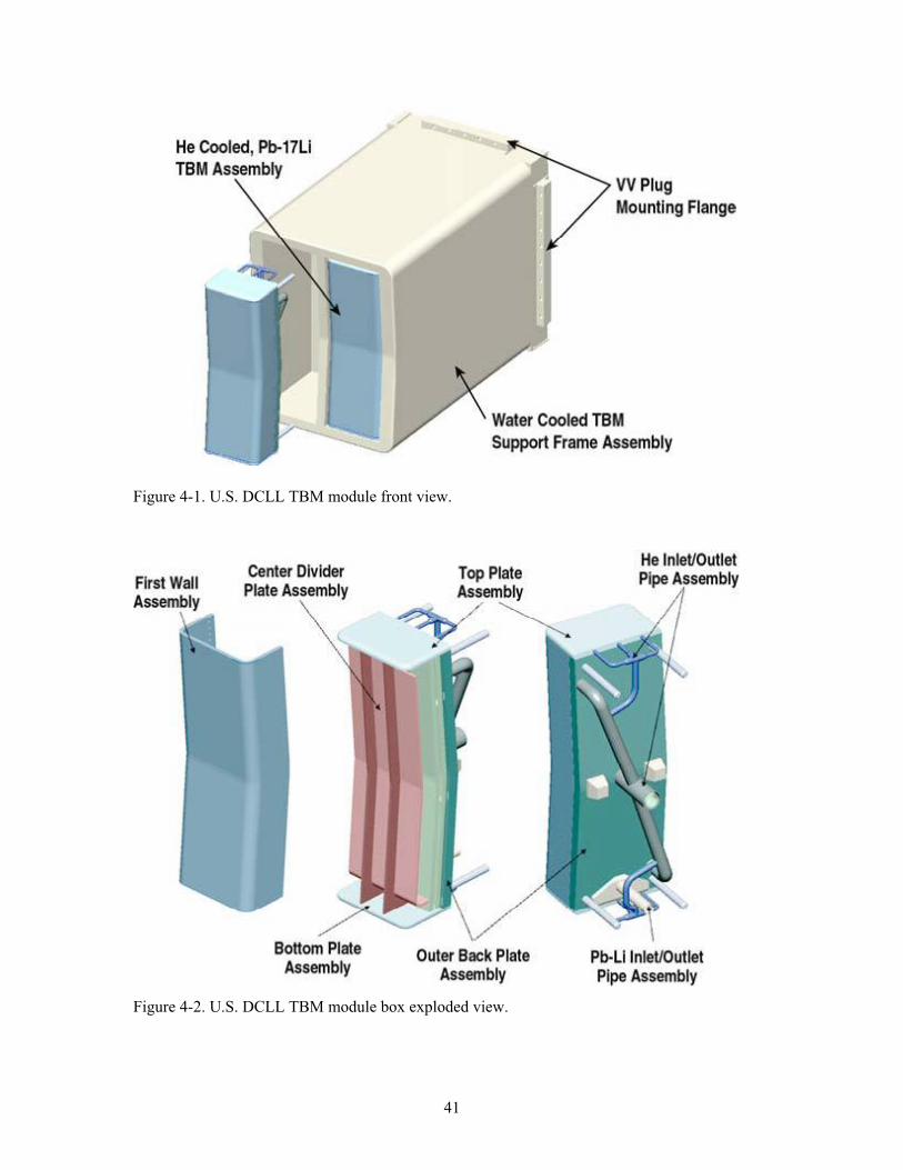
41
Figure 4-1. U.S. DCLL TBM module front view.
Figure 4-2. U.S. DCLL TBM module box exploded view.
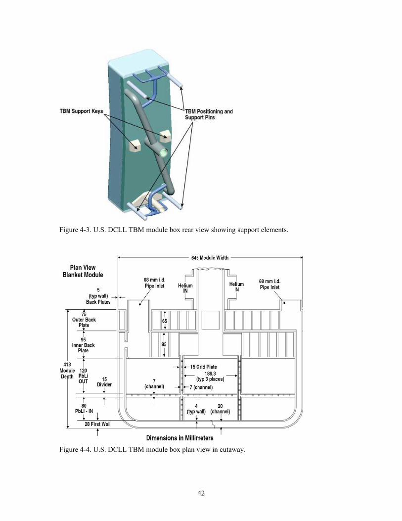
42
Figure 4-3. U.S. DCLL TBM module box rear view showing support elements.
Figure 4-4. U.S. DCLL TBM module box plan view in cutaway.
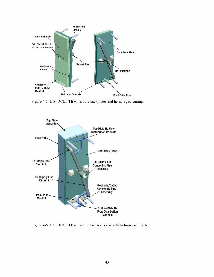
43
Figure 4-5. U.S. DCLL TBM module backplates and helium gas routing.
Figure 4-6. U.S. DCLL TBM module box rear view with helium manifolds.
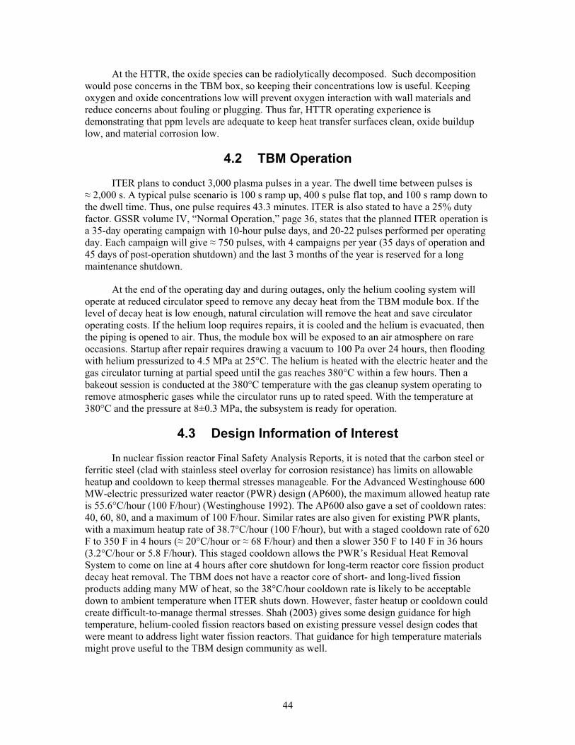
44
At the HTTR, the oxide species can be radiolytically decomposed. Such decomposition would pose concerns in the TBM box, so keeping their concentrations low is useful. Keeping oxygen and oxide concentrations low will prevent oxygen interaction with wall materials and reduce concerns about fouling or plugging. Thus far, HTTR operating experience is demonstrating that ppm levels are adequate to keep heat transfer surfaces clean, oxide buildup low, and material corrosion low.
4.2 TBM Operation
ITER plans to conduct 3,000 plasma pulses in a year. The dwell time between pulses is 2,000 s. A typical pulse scenario is 100 s ramp up, 400 s pulse flat top, and 100 s ramp down to
the dwell time. Thus, one pulse requires 43.3 minutes. ITER is also stated to have a 25% duty factor. GSSR volume IV, “Normal Operation,” page 36, states that the planned ITER operation is a 35-day operating campaign with 10-hour pulse days, and 20-22 pulses performed per operating day. Each campaign will give 750 pulses, with 4 campaigns per year (35 days of operation and 45 days of post-operation shutdown) and the last 3 months of the year is reserved for a long maintenance shutdown.
At the end of the operating day and during outages, only the helium cooling system will operate at reduced circulator speed to remove any decay heat from the TBM module box. If the level of decay heat is low enough, natural circulation will remove the heat and save circulator operating costs. If the helium loop requires repairs, it is cooled and the helium is evacuated, then the piping is opened to air. Thus, the module box will be exposed to an air atmosphere on rare occasions. Startup after repair requires drawing a vacuum to 100 Pa over 24 hours, then flooding with helium pressurized to 4.5 MPa at 25°C. The helium is heated with the electric heater and the gas circulator turning at partial speed until the gas reaches 380°C within a few hours. Then a bakeout session is conducted at the 380°C temperature with the gas cleanup system operating to remove atmospheric gases while the circulator runs up to rated speed. With the temperature at 380°C and the pressure at 8±0.3 MPa, the subsystem is ready for operation.
4.3 Design Information of Interest
In nuclear fission reactor Final Safety Analysis Reports, it is noted that the carbon steel or ferritic steel (clad with stainless steel overlay for corrosion resistance) has limits on allowable heatup and cooldown to keep thermal stresses manageable. For the Advanced Westinghouse 600 MW-electric pressurized water reactor (PWR) design (AP600), the maximum allowed heatup rate is 55.6°C/hour (100 F/hour) (Westinghouse 1992). The AP600 also gave a set of cooldown rates: 40, 60, 80, and a maximum of 100 F/hour. Similar rates are also given for existing PWR plants, with a maximum heatup rate of 38.7°C/hour (100 F/hour), but with a staged cooldown rate of 620 F to 350 F in 4 hours ( 20°C/hour or 68 F/hour) and then a slower 350 F to 140 F in 36 hours (3.2°C/hour or 5.8 F/hour). This staged cooldown allows the PWR’s Residual Heat Removal System to come on line at 4 hours after core shutdown for long-term reactor core fission product decay heat removal. The TBM does not have a reactor core of short- and long-lived fission products adding many MW of heat, so the 38°C/hour cooldown rate is likely to be acceptable down to ambient temperature when ITER shuts down. However, faster heatup or cooldown could create difficult-to-manage thermal stresses. Shah (2003) gives some design guidance for high temperature, helium-cooled fission reactors based on existing pressure vessel design codes that were meant to address light water fission reactors. That guidance for high temperature materials might prove useful to the TBM design community as well.
45
Regarding reliability of the gas coolant channels, a similar application is found in rocket nozzle cooling. Spacecraft reusable rocket engines sometimes use integral, machined cooling channels or tubular (both square and circular) cooling channels on the rocket throat and nozzle. Cryogenic liquid hydrogen fuel is first pumped through these channels to cool down the nozzle materials and then the warmed fuel is routed to the nozzle throat to be burned for thrust. These channels have been susceptible to a phenomenon termed “thermal ratcheting”. This is a failure mode where cycling cryogenic fuel as a coolant (LH2 at -253°C) on one side of the channel wall and cycling the very hot combustion reaction products (about 540°C) on the other side of the channel wall over many sessions (dozens of rocket engine operating cycles) causes the wall facing the hot side to begin to deform (Rapp 1993). This is a metal creep failure, a shape change while under stress and strain. The bulging wall has been referred to as ‘tenting out’ or ‘doghouse failure mode’ to signify the wall bulging outward toward the high heat flux and giving the appearance of a tent or roof. In some cases, the cooling channel wall deformed enough that it cracked and opened a through-wall breach. Jankovsky (1990) compared machined rocket nozzle channels to brazed tubes and found that the tubes had double the lifetime of channels. The stresses and strains in the tubing walls were 20 to 25% less than in channels. Fortunately, this failure mode is not expected to occur with the TBM cooling channels for several reasons. The TBM coolant is at elevated temperature (over 400°C) rather than cryogenic temperature (so there is no large thermal gradient on the channel walls), TBM temperatures will remain elevated between plasma shots (less heatup-cooldown thermal stress over the module box lifetime), and rocket cooling lines are often fabricated of copper tubing or milled copper passages for high heat transfer while TBM channels will be fabricated from much stronger and more creep-resistant ferritic steel. The TBM channel wall, at 4 mm, is also much thicker than rocket engine coolant channel walls at 0.89 mm.
There are also irradiation issues of importance for the blanket box. Metals as a class of materials tend to have high thermal conductivity that dissipates radiation heating and avoids radiation heating damage. Metals also tend to have high electrical conductivity that tends to dissipate the effects of charged particles (ions and electrons). The primary concern with radiation damage in metals is displacement of atoms in the metal structure and transmutation effects that change the elements within the metal alloy. As low alloy steels are irradiated past 1E+18 fast neutrons/cm2, the ultimate tensile strength and yield strength slowly begin to increase; this also means the metal gets more brittle (Ma 1983). Finer grain structures tend to resist the effects of irradiation better than coarse grain steels. The TBM steel in question here also operates at over 400°C, so there is some radiation damage ‘healing’ of the metal lattice through high temperature annealing. If ITER has a fast neutron flux of about 1E+13 n/cm2-s and the TBM lifetime is 3.6E+07 s (10,000 operating hours) (Wong 2005) then the irradiation damage at 3.6E+20 n/cm2
fast neutron fluence is reduced ductility, increased embrittlement, increased yield and tensile strengths. The 1E+20 to 1E+22 fast n/cm2 range is a threshold level for irradiation effects (Ma 1983; Kircher 1964; Glasstone 1981). 3.6E+20 n/cm2 is at the low end of the irradiation effects range, so the radiation effects of strength change, and ductility change are expected to be mild over the TBM lifetime. Two other issues are swelling and creep. Swelling has been noted to not be significant in Eurofer and other low activation ferritic steels (Schaeublin 2002) and therefore is not expected to be significant for the short lifetime TBM module. Creep is not expected to be an issue for the TBM since the highest accelerating material creep only occurs under neutron irradiation in metals at over half their melting point and at high tensile stresses (Glasstone 1981). The TBM module box will typically operate at 46o to 470°C, and the Eurofer alloy has a melting temperature of 1500°C, so the TBM operates at less than one third of the melting temperature. Fernandez (2005) stated that tests of Eurofer showed increased creep at aggressive test values (> 500°C, > 170 MPa) over 9,000 hours of testing. Creep strength deteriorated at 500°C, 200 MPa, and 15,470 hours of testing. The TBM operates at close to this temperature, but
46
at much lower stress and for less than 15,470 hours, so creep is not expected to be a reliability issue. The TBM module box can be changed out if necessary at less than 15,470 hours of operation. Evans (1992) pointed out that oxide dispersion strengthened alloys have good creep resistance at below 525°C; the TBM module box will operate below this temperature.
4.4 Related Operating Experiences Supporting the FMEA
The literature was searched for any similar operating experiences that would help support judgments of module box reliability. The module box is rather unique—a combination of gas and liquid metal coolants, high temperature (470°C) operation, a new, reduced activation alloy ferritic steel, hot isostatic press bonding, and silicon carbide usage as liner plates in the liquid metal flow channels. Some use of individual aspects of the TBM module box were found in the literature and are discussed in the failure rate data section below. The main promise of the TBM module box is that it consists solely of passive components, no active components like pumps, valves, etc. The cooling loop active components have been addressed in previous chapters.
4.5 FMEA Failure Rate Data
There is no database to draw from for the TBM module box components and parts. Nonetheless, an important concern is that without accurate failure rate data applied to the pieces and parts then the overall result will be a large value that is overly conservative (Cadwallader 1996). No published failure rate data on square cross section tubes were found in the literature search, and there are no readily available data on flat plates or manifolds in radiation and high temperature—the Pb-17Li will typically operate at 340 to 470°C but can ramp up to 650°C contained in its flow channels (Wong 2005), while the helium coolant operates at 380 to 460°C in the module box.
Some assumptions have been made to allow an initial quantification of the module box reliability so that the component fault events can be placed in frequency categories. First, the square tubes that comprise the TBM first wall (FW) are similar in width to the circular cross-section tubes used in heat exchangers. As a first approximation, steam generator tube values are applied to the TBM FW tubes. Generally, shell-and-tube heat exchangers in industry have tubes in tube bundles that can be very long (many meters) and are thin-walled, perhaps 0.75 to 1.25 mm thick, to enhance heat transfer between fluids (Cadwallader 1996a). The TBM square tubes at 4 mm wall thickness are more robust construction than heat exchanger tubes and operate at lower pressure. Considering that a fission reactor’s steam generator could have a P of 8 MPa between primary water and secondary steam and those tubes are 1 mm thick inconel 690 alloy, the TBM is built more conservatively. Most U.S. pressurized water reactor (PWR) fission plant steam generators (SGs) are U-tube units having an average 9,000 tubes per tube bundle and the tubes can be an average 30 m long (see the U.S. NRC fact sheet on Steam Generator Tube Issues, at nrc.gov/reading-rm/doc-collections/fact-sheets/steam-gen.html) then some preliminary failure rates for tubes can be obtained. There are typically four SGs per PWR plant. Therefore (4 SG/plant)(9,000 tubes/SG)(30-m/tube) gives 1.08E+06 m of tube run/plant. The operating experience event frequency for steam generator tube rupture is 7E 03/plant-year (Poloski 1999); it is worth noting that earlier work by Adams (1990) gave 9.76E 03/reactor-year. Dividing gives 7E 03/plant-year ÷ 1.08E+06 m/plant or 6.5E 09 tube ruptures per meter-year. Over the majority of the data collection time, the fission plants operated at 75% or more of a calendar year, so roughly 6,570 calendar hours per year. Therefore, the SG tube rupture failure rate is 9.9E 13rupture/m-h, which is rounded up to 1E 12 tube rupture/m-h for this preliminary estimate. Adams (1990) suggested that multiple tube rupture events would be a factor of 10 less frequent
47
than the single tube failure value. Since the TBM square tubes are thick-walled and form a bonded unit, they should be able to meet this 1E 12/m-h experience value unless outside forces act on the tubes. Another important issue is that a SG tube rupture can release appreciable flow rates, even though they are small diameter. Rupture flow rates up to 79 kg/s water (Adams 1990) have been recorded with an average of 25 kg/s. The high flow rate is a factor of ten above the makeup water supply capability. Leaks in SG tubes were much smaller flow rates, the lowest reported leak rate was 0.0003 kg/s of water and the highest at 2.5 kg/s. A PWR flows perhaps 17 Mg/s water in the primary system (Nero 1979). An estimate of typical flow in an individual PWR SG tube during normal plant operation is (17 Mg/s 4 SGs)(1 SG/9000 tubes) 0.5 kg/s, but a breach opening to lower pressure can increase the flow rate. Using Adams’ data, 78 tube leak events in 512 reactor-years would give 0.15 tube leak/reactor-year. Converting the data into tube results: (0.15 tube leaks/reactor-year)/(1.08E+06 m/reactor)(6570 h/yr) or 2.1E 11 leaks/h-m for SG tubes. As stated above, for a first approximation these round, thin-walled tubing leak failure rates will be applied to the square, thick-walled TBM tubes to estimate tube failure rate. Note that external forces, such as runaway electrons or plasma disruption energy will be treated separately. Granted, the SG and TBM materials differ; typically incoloy SG tubes versus TBM ferritic steel. The SG secondary side water-steam coolant has had chemical plateout after boiling that has contributed to tube corrosion problems while helium and vacuum should not present such problems for TBM tubes. Both the fission SG and the TBM tubes will experience the environments of high differential pressure, high flow velocity, and vibration. To give a comparison of these results, Marshall (1994) gave suggested failure rates for ferritic steel tubes with helium coolant. The analyst judgment tube leakage value was 5.4E 09/m-h and tube rupture was a factor of ten lower, 5.4E 10/m-h. The SG tube operating experience values are 2.1E 11/m-h for leakage and 1E 12/m-h for rupture, from Adams’ data, which are lower values from actual operating experiences. Since the TBM tubing is thick-walled robust construction, the thin-walled SG tube operating experience values will be applied to these tubes as a first approximation. Using Adams’ data on SG tube leaks, the average leak rate for all 64 leak events that cited a flow rate was 0.167 kg/s, or about 33% of the typical flow rate. The smallest leak event was 0.06% of the tube flow rate. The helium tubing in the TBM will operate for about 4,032 hours per calendar year. Because the helium in the tubes is operating at 8 MPa, if a breach opening occurs, it is assumed that the helium will penetrate past the plasma sprayed beryllium on the tube outer surface. A two-mm thickness of beryllium is plasma sprayed onto the front face of the tubes (Wong 2005). As an initial assumption, given the square nature of the tubes and that the tube-to-tube bond should be very strong to make the TBM withstand forces acting on it, 25% of the breach failures are assumed to leak out toward the vacuum vessel and 25% are assumed to leak in toward the Pb-17Li channels. The leaks upward or downward are believed to encounter strong bonding between tubes and are therefore expected to be halted without any further leakage.
Values to apply to square tubing:
2.1E 11/h-m leaks, smallest water leak is 0.06% of tube mass flow rate, average was 33%
1E 12/h-m ruptures, average water leak is 5000% of the typical tube mass flow rate
Leakage from the TBM has more concerns than just the module face tubes. Helium could leak out of the module box at many locations. Rivkin (2005) stated that most gas leaks (i.e., small leaks) of process gases leaking from 15 MPa gas cylinders and piping undergo a tortuous leak path and the leaks are on the order of 0.1 to 1.0 ml/minute of escaping gas. This is an STP leak rate; much gas energy is expended to overcome friction and pressure is lost in traversing a tiny leak opening. The STP density of helium is 0.179 g/l. Therefore, Rivkin’s mass leak rate would be 1.79E 05 to 1.79E 04 g/minute. If Rivkin’s very small leak rate is applied to ITER with its
48
43 minute pulses, then at most 0.008 g helium could leak into the vacuum vessel during one pulse from a small leak. The helium flowing in the TBM module box is 0.343 m3/s volume flow rate, 100 m/s velocity, 1.76 kg/s mass flow rate, at 8 MPa pressure (which is roughly half of Rivkin’s pressure). The helium density is 5.33 kg/m3. At Rivkin’s small helium leak rate, ITER could operate for a year and accumulate ~24 g helium in the vacuum vessel, and vacuum pumping on the vacuum vessel would remove some of the in-leakage helium each day. However, over time the helium accumulation in the vacuum vessel might interfere with plasma startup, so the small leak might require a maintenance shutdown to make repairs. Nonetheless, the typical small leak rate for gases does not appear to cause concern for inducing plasma disruptions. Merrill (1991) described calculations for water coolant being injected into the edge of an ITER plasma from a first wall cooling line leak. As little as 30 g of water would create a disruption with twice the disruptive intensity as a typically expected density limit disruption. A 30-g mass will be used as a tentative bound on masses likely to cause disruptions. Using the 0.06% and 33% leak rates estimated from tubing leak experience, (0.0006)(1,760 g/s flow rate) = 1.06 g/s leak rate of low pressure helium, and (0.33)(1,760 g/s) = 580.8 g/s, both of which will pose a disruption threat at the edge of the ITER plasma over a 400-second pulse.
The TBM module box bonding method of choice is hot isostatic press (HIP) bonding. Unfortunately, there is little data available on the reliability of HIP joints. There has been some fusion research testing of limited numbers of components for limited numbers of test cycles; however, the testing has not been sufficient to definitely prove that this joining is as reliable as traditional nuclear industry arc welding. At least one researcher commented that HIP was preferred over ‘leaky’ welds (Lorenzetto 2005), which gives an insight that at least some materials researchers believe that HIP joints could outperform welds. Basically, the TBM module has to perform as well as, or better than, the rest of the ITER first wall. The GSSR volume VII gives a first wall in-vessel leak as a Category III event, which has a frequency band of 1E 02 to 1E 04/yr. The TBM is about 1.9 m tall by 0.65 m wide, or 1.2 m2 FW surface area, and the entire FW is 672 m2. Thus, one TBM is 0.18% of the entire FW. Applying the Category III frequency upper bound of 1E 02/yr times 0.0018 gives a bounding value TBM leak frequency of 1.8E 05/yr. Applying this value to the TBM module edges that could leak appreciable amounts of helium into the vacuum vessel gives a result of 1E 07/h-m for bond leakage. Comparing this value to Buende’s weld reliability values (Buende 1991) shows this estimate is at the high end of the range of nuclear-grade arc welding failure rates. Therefore, for this preliminary work, HIP bonds will be assumed to be as good as arc welding and will be given welding failure rates.
ITER is built to withstand thousands of plasma disruptions; plasma disruptions are considered to be part of normal operations (GSSR 2001, section VII.1.2.2). Consequently, the TBM must also withstand disruptions. The ITER GSSR volume III states that approximately 10% of plasma shots will end in disruptions. This 10% value has been a long-standing assumption for disruptions and another assumption is that 10% of shots will be long duration plasma power transient events (Smid 1996). It is expected that most of these disruptions would occur in the H-H and D-D phases of operations, but some level of disruptions will still occur in the high power D-T operation despite efforts at disruption avoidance. Having no better guidance for D-T operation, the GSSR volume III information is used. ITER plans to operate 3,000 pulses/yr. Therefore, we would typically expect 300 disruptions/yr. An exceptionally powerful disruption would be required to lead to damage beyond the planned-for wall erosion. The physicists and machine operators would strive to avoid such high energy disruptions. Considering the rarity of hazardous disruptions that have occurred in existing tokamaks, perhaps a few events in thousands of plasma shots per year—such as the Joint European Torus (JET) experience (Bertolini 1995), and noting disruption statistics in the Axi-Symmetric Divertor Experiment (ASDEX) that showed many moderate-intensity disruptions which did not damage the machine (Zohm 1993), a high energy
49
disruption would only occur very rarely. Analyst judgment based on these existing tokamak experiences is that very severe disruptions would occur in perhaps 0.1% of all disruptions; that assumed likelihood means 0.3 high energy disruptions per year. GSSR volume III also states that 70% of the disruptions are assumed to deliver their energy to the divertor. The other 30% of disruptions are assumed to deliver their energy to the FW. Applying the 30% value to 0.3 high energy disruptions gives 0.09 disruption per year on the FW with high energy to damage the FW or TBM. GSSR volume III states to assume a wall surface area of 20 m2 being affected by the disruption for erosion purposes while the 2003 ITER Safety Analysis Data List (SADL 2003), section 2.2, and GSSR volume VII section 1.2.2 both state that the disruption would deliver its thermal energy to the entire 672 m2 (or 680 m2) FW. However, for conservatism, a disruption-affected 20 m2 wall area will be assumed here. Assuming that a high-energy disruption has equal probability of impacting anywhere on the FW, then having some of the 20 m2 disruption area overlay on the TBM face could create TBM damage. An analyst judgment was made that 25% of the TBM face or more would need to receive the disruption heat energy to cause TBM overheat (differential thermal overstress on the TBM face) damage or failure. Quartering the TBM face and overlaying a corner of a 4.5 m x 4.5 m ( 20 m2) surface for each one-fourth of the TBM gives a total area of 80 m2 the disruption could impinge and affect a portion of the TBM. Using the FW surface area, the likelihood of the TBM being affected is 80/672 = 0.12. A high energy disruption partially impinging on the TBM is (0.09 severe disruptions/yr)(0.12 area ratio)=1.1E 02/yr, a Category II event. This is a crude quantification, but satisfactory for the preliminary nature of this assessment.
The TBM must also withstand the electromagnetic jxB plasma forces generated by a plasma disruption. These resulting mechanical forces apply torque to the FW and the TBM box, attempting to rotate the TBM box around the axis of its inlet-outlet pipework. The TBM box is cantilevered in the water-cooled frame, normally with 20 mm clearance between the box and the frame around the entire periphery of the TBM box. The 4 metal bar support pins and the 2 metal block support keys hold the TBM in place against these forces and the normal vibration forces that occur in plasma operations. As an analyst judgment, having one failed support pin or just one failed support block is insufficient to move the TBM box against the frame. Analyst judgment also concludes that having one failed support pin and one failed support block will allow disruption forces to move the TBM box to contact its water-cooled frame. Having these two low-failure rate components fail in an overlapping time frame is expected to be a very low probability event. At 300 disruptions per year, it is expected that there will be 1-2 disruptions per operating day. To address consequences of TBM box motion, the water-cooled frame information was examined. The frame wall thickness is stated to be greater than that of the 4-mm-thick TBM wall but the actual thickness was not found in the 2005 TBM design description document. While the distance to travel is small (20 mm), the forces can be very large over very short disruption times and would lead to high metal-to-metal pressure at contact points. That mechanical pressure and stress could result in tearing the side of the TBM FW face. This is only an analyst judgment at present, calculations must be performed on this postulated event scenario. If the TBM box were to fail, helium would leak to the vacuum vessel. It is possible, although improbable, that the TBM might be sufficiently damaged internally to leak Pb-17Li to the helium coolant passages and eventually leak Pb-17Li to the vacuum vessel. The water-cooled frame must be evaluated to verify that it is robust against such events so that there is not a water leak into the vacuum vessel.
Failure rates for simple mechanical parts are not widely published. It is expected that the failure rates for these simple steel parts can vary due to the service environment (i.e., corrosion, elevated temperature, thermal cycling, pressure cycling, etc.) and planned usage (i.e., stress loading, strain loading). An assumption is also made that these parts fabricated from reduced activation ferritic steel will perform on par with components fabricated from traditional carbon
50
steel and low alloy steel. For all of these reasons, quantification of these passive component failure rates is highly preliminary at this time. A few failure rates are shown here (NPRD 1994; Moss 2005; Smith 2005; Green 1972) to provide some insight on elementary mechanical part failure rate magnitudes:
Part Failure Rate Machine bolt 2E 08/hMachine nut 2E 08/hShaft 2E 08 to 3E 08/hHighly stressed shaft 2E 07/hBracket 3E 07/hChassis 9.2E 07/h Clevis 4.526E 07/h Pin 2.6E 09/h
These cast shapes, small solid metal mechanical parts, can reach magnitudes of 1E 07 to 1E 09/h for basic “failure to function” failure rates. Bentley (1993) also reported some mechanical component failure rates: nuts, bolts, rods, shafts all had a breakage failure rate of 2E 08/h, spring or mechanical joint breakage was 2E 07/h. Bentley’s values all agree well with those listed above. As a crude comparison, metal part data from Vo (1995) is used. Vo (1995) gave operating experience failure rates and expert elicitation data values on very large metal structural parts used in hydroelectric dam applications where water exerts high stress and also strain on the metal components. A metal gate “all modes” failure rate was 1E 05/h, gate pins and beams were 2E 06/h, metal supports (ribs, stringers, etc.) for gates were 3E 08/h, shear pins were 1E 05/h, metal stay vanes were 6E 09/h, metal wicket gates were 1.4E 07/h, and metal bars were 2E 07/h. Vo did not decompose these “all modes” values into their respective failure mode contributions. It is expected that the majority of the failure modes would be failure to function (binding, bending, surface corrosion) rather than catastrophic cracking failure due to fatigue or material flaw (Smith 2005; FMD-97 1997). These values at 1E 05 to 6E 09/h for very large, massive metal parts scatter around those listed above for smaller metal parts (automobile parts, machine parts, etc.) and show that low failure rates on the order of 1E 07/h and lower for mechanical pieces and parts are plausible even on the large scale of hydroelectric dams. For the TBM, a single thickness metal plate failure rate is chosen by the analyst to be 1E 08/h for failure to support or maintain its shape under service conditions; this value is based partially on the list above and on the failure rate range guidance given by Carter (1986). A failure rate of 3E 09/h is used for the welded pins on the TBM box, weighted by the FMD-97 data for pin failure modes (bend, 78%; break, 22%). Support keys (steel blocks) are assigned a failure rate of 3E 08/h for failure to function, as an initial approximation. This failure rate is assumed to be 50% deformation and 50% cracking, based on similar types of parts described in FMD-97. A butt weld failure rate of 6E 09/hour-weld, taken from Buende (1991), is used for the support key and support pin ‘detachment’ failure mode.
The grid plates and coolant channel plates in the TBM are not as easily quantified for failure rates. These plates are dual-walled units. While the presence of two walls tends to suggest using independent failure rates for two plates, a more conservative assumption of two adjacent plates set side-by-side that experience the same environment - thermal load, thermal cycling, and radiation - are unlikely to have truly independent failure rates. Common causes could occur despite the fact that a material crack cannot propagate through a gap between plates. The typical ‘beta factor’ method was chosen to address these dual wall components. Vesely (2002) reports a typical beta factor for initial assumptions is 0.1 and Andrews (1993) gives data which shows that most beta factors are less than 0.1, rather in the 0.04 range. Therefore, using beta=0.1 for the
51
present time should be a conservative, reasonable assumption. A beta factor of 0.1 on the single plate failure rate has been used to describe the dual-walled unit failure rate, that is 0.1x(1E 08/h). Therefore, the cruciform grid plate failure rate is 1E 09/hour for failure to support and to maintain its shape. The back plates with their coolant channels are also 1E 09/h for failure to support and to maintain shape. It is assumed if the cruciform grid plate deforms, the silicon carbide inserts will fail since ceramic materials tend to be weak against bending stresses. Back plate channel plugging is assigned a failure rate of 3E 06/h from Blanton (1993). Back plate leakage is assumed to be a single wall plate failure rate.
The flow channel inserts are rectangular cross section ducts, or large flow ducts, of silicon carbide with a U-cap beneath the top plate to redirect Pb-17Li flow back down the TBM toward the outlet piping. No failure rate data were found for this rectangular duct component so assumptions are explained here. The silicon carbide “flow channel inserts,” or FCIs, have been described as liner plates (see Smolentsev 2006). These have been provided in the design to reduce magnetohydrodynamic effects of flowing Pb-17Li in the ITER magnetic field. The FCIs are an integral part of the MHD pressure drop and thermal profiles of the TBM; any flaws or failures of the FCI significantly impact the MHD and thermal behavior of the TBM (Wong 2005). The four FCI plates fit together as tongue-and-groove connections, there is no bonding, brazing or welding of the composite material. The FCIs have a thin sealing layer of crystal SiC to prevent penetration of the liquid metal into the SiC (Smolentsev 2006). The layer is included in the SiC failure rate. The DCLL TBM FCIs are 5-mm thick, operate in the 650—700°C range, and see Pb-17Li coolant moving at only a 6 to 10 cm/s flow speed. There is radiation damage in the TBM since it is part of the ITER first wall. Given all of these operating conditions, similar experiences with large-scale usage of SiC were sought. SiC has been used to great advantage in gas turbines under very high temperatures (1,200 to 1,400°C) and stresses. The slow crack growth phenomena that can lead to catastrophic failure appears to occur only above 1,000°C (DOE 1994). Lin (1994) noted that Nicalon fiber-reinforced SiC composite had reduced strength at elevated temperatures (100 MPa under 950°C and 70 MPa at 1,150°C). The TBM will operate well below the 950°C temperature, making slow crack growth a highly unlikely failure mode.
Another use of silicon carbide has been to make electrical “surge arrestor” insulators, which have had very low material failure rates. SiC has also been used to make heat transfer components, notably gas-gas flat plate and also tubular heat exchangers to recover waste heat from flue gases in fossil fuel combustion processes. Silicon carbide has also been tested as a fission reactor fuel pebble cladding material, which would never have been considered if SiC could not function well in high radiation environments with fast neutrons at fluxes equal to and higher than the ITER flux. Fission fuel cladding is also called upon to continue confining the fuel during spent fuel storage, so the cladding must have high longevity. This SiC application to fission fuel cladding suggests that SiC material can easily withstand the nuclear environment inside the TBM module box. The failure rates from these applications were studied to support analyst judgment of a flow channel insert failure rate.
Lat (1981) gave some data on power distribution arrestors. These units were estimated to be 0.6-m tall by 0.1-m diameter, used in a 21 kV power distribution system. Taking away moisture ingress failures, vandalism, and lightning strike failure modes left 22 units failed out of 300,000 ceramic units included in a 3-month study. Those data gave a point estimate failure rate of: 22 failures/[(300,000 units)(2190 hours)] = 3.3E 08/unit-hour. Thus, loss of mechanical integrity (cracking, etc.) is a low failure rate. This low failure rate is indicative that SiC ceramic surge arrestors are passive components that function well when they are kept free of moisture and external influences.
52
SiC heat exchanger tubing in tests have not shown any failures by flaws or subcritical crack growth, but the small numbers of tubes in short duration tests have not accumulated enough time to provide attractively low failure rates. Unfortunately, there is little operating experience data compiled for SiC tubes. Qualitatively, Reuter (1986) determined that if the SiC tubes were not overstressed, they could operate indefinitely, at least 12 months (8,760 hours) continuous operation, in a high temperature burner-duct recuperator that uses waste heat from an industrial steel soaking pit to preheat air to 1,255 K. Ten thousand hours is only a short time longer than Reuter’s prediction and is likely within the useful lifetime bound Reuter was addressing. Seven recuperator tubes were fabricated and exposed to these test conditions:
Flue Gas Temperature, K (C) Exposure time (hours) 977 (704) 25 1086 (813) 360 1227 (954) 75 1311 (1038) 25 1422 (1149) 35 1533 (1260) 5 Total 526 hours of testing Note: A 2-hour ramp up to test temperature was performed for each test temperature.
The tubes operated without difficulty; no creep, no corrosion, no thinning of the walls, and no crack propagation was noted. Unfortunately, this amount of operating hours is very low and the number of tubes tested is very small; there is only low confidence in a failure rate estimate from this single batch trial of a few components. As a first attempt at quantification, this data set is analyzed as follows. Considering that 700°C is a high temperature for fusion, the exposure time hours are summed as high temperature operation. The tubes were roughly 2 meters long, and 6.35 mm thick. A simple point estimate for reliability tests with no failures would be to assume a Chi-squared distribution (IAEA 1992). A 50% Chi-squared “average” failure rate would be 0.6931/(number of units tested•test time), giving 0.6931/(7 tubes•526 hours•2 m/tube), or 9.4E 05/m-h. A 95% confidence limit for that failure rate would be 2.9957/(number of units tested•test time), or 2.9957/(7 tubes•526 hours•2 m/tube) = 4.1E 04 per m-h for all modes of failure. This average failure rate is rather high for heat exchanger tubing, so it is not an attractive value, but the implication from the test session is that the silicon carbide tubes performed well, showed no degradation after 52 hours, and could have operated much longer at elevated temperature without failure. Therefore, this crude estimate, generated from very sparse data, could be considered as an upper bound tubing failure rate. It is also noted that temperature ramp-up was 2 hours (1260°C—20°C for a delta-temperature of 1240°C) or 10.3°C per minute, which is more aggressive heat-up than is used in the nuclear industry for metals.
Hindman (1995) described an air heat exchanger used on an incinerator to recover heat from the incinerator flue gas. This ceramic tube heat exchanger used SiC-alumina and also zirconia tubes. Seven SiC tubes were used in a half-year test. Three tubes failed due to steam backflow. Planned weekend outages and air fan trips allowed some steam to enter the tubes on the air side, and the steam condensed as the tubes cooled for a weekend shutdown. During the next incinerator startup, thermal stresses generated by the condensate water heat absorption as it boiled caused the tubes to break. These tubes were replaced (note: apparently these tubes cannot be repaired in-situ, they must be replaced—this is an important consideration for the FCIs in the DCLL TBM, that faulted FCIs will likely require either the Pb-17Li loop to shut down and the TBM continue to operate only on helium cooling or TBM module changeout to repair the FCI in the hot cell). The tube operating time data is given below:
53
Number of Tubes Operating weeks Total tube length-time (m-h) 4 27 17,010 3 19 [failed at 19 wks] 8,977.5 3 [replacement tubes] 8 3,780 Total 29,767.5 Note: The tubes were 1.5 meters long. An operating week was about 105 hours (Monday through Friday operation, for 24 hours/day but starting on Monday afternoons). The average week was 105 on-line hours.
The tubes operated with 982°C to 1,038°C shell-side incinerator flue gas at 1,633 kg/hour and a pressure drop of 0.046 atmosphere. The tube-side air entered at 425°C at 1,633 kg/hour and a pressure drop of 0.067 atmosphere. The design heat flux for a tube was 17.8 kW/m2. The tube walls varied between 3.2 mm and 6.4 mm thick and had a 10.2 cm outside diameter. The average tube wall temperature was 516°C. Air flowed down a metal tube “bayonet” within the ceramic tube and then reversed direction and flowed up the 0.95 cm–width annulus out of the tube. Even with this higher temperature and longer operating time than the Reuter data above, there was no creep, wall thinning, corrosion, or cracking except for the admission of boiling water than induced thermal stress cracking.
Because the tube failures in the Hindman test were due to external operational influences, that is, foreign material intrusion (condensed steam) rather than a tube material flaw, flow vibration, or a design issue, the tube failures are not counted as part of the operating experience for this first approximation of a failure rate to be applied to the TBM. Following the IAEA (1992) guidance, a 50% Chi-squared failure rate would be 0.6931/(17,010+8977.5+3780 meter-hours) = 2.3E 05/m-h. A Chi-squared 95% upper bound failure rate would be 2.9957/(2•29,767.5) or 5E 05/m-h. This average failure rate is over a factor of ten less than the value found in the 526-hour test discussed above. This failure rate reduction with additional operating time and more aggressive operating parameters in heat exchange tubes, and the data from Lat (1981) about the very low electrical insulator failure rates, all suggest that the SiC tubing component could survive longer operating times. There was a concern that running at the design heat flux could cause the tubes to suffer interply or intraply damage, especially transverse to the fiber direction. Those forms of damage would not necessarily cause catastrophic tube wall failure. The test results showed that the tubes could handle more heat load than predicted, there was no interply or intraply damage. Reuter (1986) examined fracture mechanics of SiC and stated that if a safety factor of 5 to 10 on material stress was used [note—this high safety factor means keeping the tube internal pressure, wall thermal stresses, flow-induced mechanical stresses, and all other stresses low], then the probability of tube failure during its service life would be below 1E 04. Since the TBM would require replacement if there was a fault in the FCIs, it is assumed in this preliminary work that safety factors on the FCIs would be high. This concept of keeping the stress loading small to prolong lifetime has long been used in electronics parts (e.g., parts derating) and has also been seen in C-ring tests of ceramic materials (Sandifer 1994). Considering that the tubing described above operated at similar or higher temperatures than the TBM and that the tube wall thicknesses are very similar to the 5-mm thick TBM FCI, and that the TBM FCIs should experience only low mechanical stress due to close tolerances to their support grid plates, then the 1E 04 cracking failure probability over the TBM service life of 10,000 hours appears to be reasonable to apply to the FCIs. SiC failures due to flaws from inclusions, slow crack growth, or any other inherent faults would be 1E 08/duct-hour for each of the FCI ducts. It is noted that the “tongue-in-groove” plate connections could provide sites for collecting impurities from the flowing Pb-17Li. Any vibration of SiC duct plates with impurities present could cause scoring of the SiC if the impurities are sufficiently hard-surfaced, such as metal precipitates or metal oxides.
54
Scoring could result in fracture and subsequent failure of the tongue-in-groove joints. Use of magnetic traps or some other type of RAFS metal oxide traps is advisable to capture metal oxides from the flow stream to keep the metals out of the TBM module flow channels.
The dual-walled inner and outer back plates also pose an interesting challenge for quantification. The failure modes of interest are deformation, fracture or cracking, and helium flow failures of plugging or flow blockage, and fouling. Deformation is treated like other plates described above despite the second dual-walled back plate unit being present to give more structural support to the other back plate. Deformation of the inner plate is believed to overstress the FCIs and restrict, but not halt, helium flow within the inner back plate. Deformation of the outer back plate is believed to not overstress the FCIs but is expected to overstress the helium piping connections to the back plate outer wall to the point of multiple leak formation.
The plasma-sprayed beryllium coating on the face of the TBM is also a concern. Castro (1995, 1996, 1998, 1999) tested 4 plasma sprayed samples for 3,000 cycles each at 1 MW/m2 and there were no failures in any of the samples. Ramping up to 3 and 5 MW/m2 for 20-second cycles led to beryllium damage and hot spot formation on the substrate in only a few cycles. Therefore, assuming that the surface area is not a driving issue for good bonding between plasma-spray and substrate joining, then using the IAEA (1992) approach, the failure rate of debonding is zero failures in 4x3,000 cycles, or a failure rate of 0.6931/12,000 = 5.8E 05 debondings per cycle. If the TBM lives for 5 years and sees 15,000 pulses, then (15,000)(5.8E 05) = 0.87 chance of coating debonding. The JET experiment has had beryllium metal components and evaporative deposition beryllium coatings in use in both D-D and D-T operations. JET experiences included beryllium droplet intrusion into the plasma; these droplets led to high beryllium concentration in the plasma and reduced fusion neutron production but not plasma disruptions (Loarte 2005). At a beryllium density of 1.85 g/cm3, and droplets of a reasonably large size, 6.5 mm diameter (or 0.146 cm3), gives 0.27 gram-Be per drop. Therefore, over 100 drops in proximity at the plasma edge would be needed to reach the 30-gram level determined by Merrill (1991). Despite this evidence to the contrary, the TBM safety work (Wong 2005) assumes a plasma disruption occurs if the beryllium coating debonds or melts and sends beryllium out from the TBM face into the edge of the plasma.
4.6 TBM Preliminary FMEA Results
The TBM module box FMEA covered the module in normal, pulse operation. If needed, future work can expand the FMEA to cover other helium operating modes of the DCLL TBM design, e.g., bakeout.
The preliminary FMEA on the module box is given in Appendix C. The main results were not surprising for this small portion of the ITER first wall. There are, however, a number of single faults that would prudently result in TBM shutdown with consequent ITER shutdown. The ITER project may not wish to accept this additional unavailability arising from the TBM. Table 4-1 summarizes the PIEs from the module box FMEA results (the PIE format and definitions are given in Section 2). Only the events involving the module box are considered in this FMEA. Because the module box contains both helium and Pb-17Li coolants, there are several initiating event categories included in this FMEA.
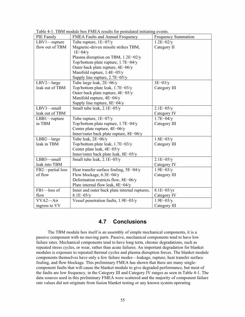
55
Table 4-1. TBM module box FMEA results for postulated initiating events. PIE Family FMEA Faults and Annual Frequency Frequency Summation LBV1—ruptureflow out of TBM
Tube rupture, 1E 07/y Magnetic-driven missile strikes TBM, 1E 04/y Plasma disruption on TBM, 1.2E 02/y Top/bottom plate rupture, 1.7E 04/y Outer back plate rupture, 4E 06/y Manifold rupture, 1.4E 05/y Supply line rupture, 2.7E 05/y
1.2E 02/y Category II
LBV2—largeleak out of TBM
Tube large leak, 2E 06/y Top/bottom plate leak, 1.7E 03/y Outer back plate rupture, 4E 05/y Manifold rupture, 4E 04/y Supply line rupture, 8E 04/y
3E 03/y Category III
LBV3—small leak out of TBM
Small tube leak, 2.1E 05/y 2.1E 05/y Category IV
LBB1—rupturein TBM
Tube rupture, 1E 07/y Top/bottom plate rupture, 1.7E 04/y Center plate rupture, 4E 06/y Inner/outer back plate rupture, 8E 06/y
1.7E 04/y Category III
LBB2—largeleak in TBM
Tube leak, 2E 06/y Top/bottom plate leak, 1.7E 03/y Center plate leak, 4E 05/y Inner/outer back plate leak, 8E 05/y
1.8E 03/y Category III
LBB3—small leak into TBM
Small tube leak, 2.1E 05/y 2.1E 05/y Category IV
FB2—partial loss of flow
Heat transfer surface fouling, 5E 04/y Flow blockage, 6.3E 04/y Deformation restricts flow, 8E 06/y Plate internal flow leak, 8E 04/y
1.9E 03/y Category III
FB1—loss of flow
Inner and outer back plate internal ruptures, 8.1E 05/y
8.1E 05/yr Category IV
VVA2—Air ingress to VV
Vessel penetration faults, 1.9E 03/y 1.9E 03/y Category III
4.7 Conclusions
The TBM module box itself is an assembly of simple mechanical components, it is a passive component with no moving parts. Passive, mechanical components tend to have low failure rates. Mechanical components tend to have long term, chronic degradations, such as repeated stress cycles, or wear, rather than acute failures. An important degradation for blanket modules is exposure to repeated thermal cycles and plasma disruption forces. The blanket module components themselves have only a few failure modes—leakage, rupture, heat transfer surface fouling, and flow blockage. This preliminary FMEA has shown that there are many single-component faults that will cause the blanket module to give degraded performance, but most of the faults are low frequency, in the Category III and Category IV ranges as seen in Table 4-1. The data sources used in this preliminary FMEA were scattered and the majority of component failure rate values did not originate from fusion blanket testing or any known system operating
56
experiences. Based on existing results, some of the identified component faults in the TBM module box will cause the box to overheat and this could lead to mechanical failure due to stresses from thermal expansion. Such failures will result in taking the TBM off-line and consequently taking ITER off-line until the TBM module box can be replaced. Overall, the TBM module box faults do not necessarily result in radiological releases that threaten the public, but they do impact ITER availability. Based on these results, design consideration should be given to testing the TBM components in fusion environments.
57
4.8 References
Adams, 1990. J. P. Adams and M. B. Sattision, “Frequency and Consequences Associated with a Steam Generator Tube Rupture Event,” Nuclear Technology, 90 (1990) 168-185.
Andrews, 1993. J. D. Andrews and T. R. Moss, Reliability and Risk Assessment, Longman Scientific & Technical, Essex, England (1993) chapter 8.
Bentley, 1993. J. P. Bentley, An Introduction to Reliability and Quality Engineering, Longman Scientific and Technical Publishers, Essex, UK, 1993, table 3.1.
Bertolini, 1995. E. Bertolini, M. Buzio, P. Noll, T. Raimondi, G. Sannazzaro, M. Verrecchia, “Engineering Analysis of JET Operation,” Proceedings of the 16th IEEE/NPSS Symposium on Fusion Engineering (SOFE 95), Champaing, IL, October 1-5, 1995, Institute of Electrical and Electronics Engineers, New York (1995) 464-469.
Blanton, 1993. C. H. Blanton and S. A. Eide, Savannah River Site Generic Data Base Development, WSRC-TR-93-262, Westinghouse Savannah River Company, Aiken, SC, June 30, 1993.
Buende, 1991. R. Buende, S. Fabritsiev, and V. Rybin, “Reliability of welds and brazed joints in blankets and its influence on availability,” Fusion Engineering and Design, 16 (1991) 59-72.
Cadwallader, 1996. L. C. Cadwallader and T. D. Marshall, "Component Reliability Data Estimation for Fusion Safety and Risk Assessment," Proceedings of the International Topical Meeting on Probabilistic Safety Assessment (PSA '96), Park City, UT, September 29-October 3, 1996, volume 1, pages 637-648.
Cadwallader, 1996a. L. C. Cadwallader, Heat Exchanger Performance, ITER engineering design file ITER/US/96/EN/SA-03, Idaho National Engineering Laboratory, April 29, 1996.
Carter, 1986. A. D. S. Carter, Mechanical Reliability, second edition, John Wiley & Sons, Inc., New York, 1986, page 177.
Castro, 1995. R. G. Castro, P. W. Stanek, K. E. Elliot, D. L. Youchison, R. D. Watson, D. S. Walsh, “Plasma-Sprayed Beryllium for ITER,” Proceedings of the 16th IEEE/NPSS Symposium on Fusion Engineering (SOFE 95), Champaign, IL, October 1-5, 1995, Institute of Electrical and Enectronics Engineers, New York (1995) 381-384.
Castro, 1996. R. G. Castro, P. W. Stanek, and K. E. Elliott, “The Structure, Properties and Performance of Plasma-Sprayed Beryllium for Fusion Applications,” Physica Scripta, T64(1996) 77-83.
Castro, 1998. R. G. Castro, K. E. Elliot, R. D. Watson, D. L. Youchison, K. T. Slattery, “Fabrication and high heat flux testing of plasma sprayed beryllium ITER first wall mock-ups,” Journal of Nuclear Materials, 258-263 (1998) 252-257.
Castro, 1999. R. G. Castro, K. E. Elliott, K. J. Hollis, A. H. Bartlett, and R. D. Watson, “The development of beryllium plasma spray technology for the International Thermonuclear Experimental Reactor,” presented at the 1999 Mexican American Engineers and Scientists
58
(MAES) International Symposium, Career Fair and Trade Expo, San Antonio, TX, 20-23 January 1999, also LA-UR-99-58, CONF-990109, Los Alamos National Laboratory, Los Alamos, NM (1999).
Derdiger, 1981. J. A. Derdiger, K. H. Bhatt, W. E. Siegfriedt, Component Failure and Repair Data for Coal-Fired Power Units, EPRI-AP-2071, Electric Power Research Institute, Palo Alto, CA, October 1981.
DOE, 1994. Ceramic Stationary Gas Turbine Development, DOE/CE/40960-T2, prepared for the U.S. DOE by Solar Turbines Incorporated, September 1994, chapter 7.
Eide, 1991. S A. Eide et al., Component External Leakage and Rupture Frequency Estimates,EGG-SSRE-9639, Idaho National Engineering Laboratory, November 1991.
Evans, 1992. R. W. Evans, J. Preston, B. Wilshire, and E. A. Little, “Creep transients in a nuclear-grade ODS ferritic steel,” Journal of Nuclear Materials, 195 (1992) 24-28.
Fernandez 2005. P. Fernandez, A. M. Lancha, J. Lapena, R. Lindau, M. Rieth, M. Schirra, “Creep strength of reduced activation ferritic/martensitic steel Eurofer’97,” Fusion Engineering and Design, 75-79 (2005) 1003-1008.
FMD-97, 1997. Failure Mode/Mechanism Distributions, 1997, FMD-97, Reliability Analysis Center, Rome Laboratory, Rome, New York, December 1997, pages 2-236 to 2-237.
Green, 1972. A. E. Green and A. J. Bourne, Reliability Technology, John Wiley & Sons, Inc., New York, 1972, Table A7.
GSSR, 2001. Generic Site Safety Report, Volume VII, “Analysis of Reference Events,” ITER report G 84 r1 6 01-07-10 R 1.0, 2001, page 82.
Hannaman, 1978. G. W. Hannaman, GCR Reliability Data Bank Status Report, GA-A14839, General Atomic Company, San Diego, CA, July 1978.
HFIR, 1988. The High Flux Isotope Reactor Probabilistic Risk Assessment, final report, PLG-0604, Pickard, Lowe and Garrick, Inc., Newport Beach, CA, January 1988.
Hindman, 1995. D. L. Hindman, Research and Development of a Ceramic Fiber Composite Heat Exchanger: Final Report, Phase III, DOE/ID/12868—1, volumes 1 and 2, July 1995.
IAEA, 1992. Manual on reliability data collection for research reactor PSAs, IAEA-TECDOC-636, International Atomic Energy Agency, January 1992, chapter 9.
Jankovsky, 1990. R. S. Jankovsky and J. M. Kazaroff, A Life Comparison of Tube and Channel Cooling Passages for Thrust Chambers, NASA TM-103613, accession number N91-11059, Lewis Research Center, Cleveland, OH, October 1990.
Lat, 1981. M. V. Lat and J. Kortschinski, “Distribution Arrestor Research,” IEEE Transactions on Power Apparatus and Systems, PAS-100 (1981) 3496-3505.
59
Lin, 1994. H.-T. Lin, P. F. Becher, and P. F. Tortorelli, Elevated Temperature Static Fatigue of a Nicalon Fiber-Reinforced SiC Composite, CONF-941144-95, Oak Ridge National Laboratory, 1995.
Loarte, 2005. A. Loarte, G. Saibene, R. Sartori, D. J. Campbell, P. J. Lomas, G. F. Matthews and EFDA-JET workprogramme collaborators, “A new look at JET operation with Be as plasma facing material,” Journal of Nuclear Materials, 337-339 (3005) 816-820.
Loftness, 1964. R. L. Loftness, Nuclear Power Plants: design, operating experience and economics, Van Nostrand Reinhold, New York, 1964, chapter 6.
Lorenzetto, 2005. P. Lorenzetto, B. Boireau, C. Boudot, P. Bucci, A. Furmanek, K. Ioki, J. Liimatainen, A. Pecock, P. Sherlock, S. Tahtinen, “Manufacture of blanket shield modules for ITER,” Fusion Engineering and Design, 75-79 (2005) 291-296.
Moss, 2005. T. R. Moss, The Reliability Data Handbook, ASME Press, American Society of Mechanical Engineers, New York, 2005, Appendix G.
Marshall, 1994. T. D. Marshall and L. C. Cadwallader, In-Vessel Tubing Failure Rates for Selected Materials and Coolants, EGG-FSP-10928, Idaho National Engineering Laboratory, March 1994.
Merrill, 1991. B. J. Merrill and S. C. Jardin, “Coolant Ingress Induced Disruption Calculations for ITER,” Fusion Technology, 19 (1991) 1278-1283.
Nero, 1979. A. V. Nero, A Guidebook to Nuclear Reactors, University of California Press, Berkeley, CA, 1979, chapter 5.
NPRD, 1994. Nonelectronic Parts Reliability Data, 1995, NPRD-95, Reliability Analysis Center, Rome, NY, July 1994.
NUREG, 2007. Industry-Average Performance for Components and Initiating Events at U.S. Nuclear Power Plants, NUREG/CR-6928, U.S. Nuclear Regulatory Commission, February 2007.
Pinna, 2006. T. Pinna, Failure Mode and Effect Analysis for the European Helium Cooled Pebble Bed (HCBP) Test Blanket Module, FUS-TN-SA-SE-R-152, draft report, ENEA Frascati, October 2006.
Pinna, 2006a. T. Pinna, Failure Mode and Effect Analysis for the European Helium Cooled Lithium Lead (HCLL) Test Blanket Module, FUS-TN-SA-SE-R-155, draft report, ENEA Frascati, November 2006.
Poloski, 1999. J. P. Poloski, D. G. Marksberry, C. L. Atwood, and W. J. Galyean, Rates of Initiating Events at U.S. Nuclear Power Plants: 1987-1995, NUREG/CR-5750, INEEL/EXT-98-00401, Idaho National Engineering and Environmental Laboratory for the U.S. Nuclear Regulatory Commission, February 1999.
Rapp, 1993. D. C. Rapp, Reliability Assessment of Thrust Chamber Cooling Concepts Using Probabilistic Analysis Techniques, NASA/CR-190785, National Aeronautics and Space Administration, June 1993.
60
Rivkin, 2005. C. H. Rivkin, editor, The NFPA Guide to Gas Safety, National Fire Protection Association, Quincy, MA (2005) chapter 8.
Reuter, 1986. W. G. Reuter, Applicability of Fracture Mechanics to Lifetime Prediction of B&W Ceramic Heat Exchanger Tubes, DOE/ID-10171, U.S. Department of Energy Office of Industrial Programs, November 1986.
SADL, 2003. H.-W. Bartels, H. Okada, L/ Topilski, and V. Barabash, editors, Safety Analysis Data List, version 4.0.3, ITER number G 81 RI 10 03-08-08 W 0.1, International Thermonuclear Experimental Reactor International Team, Safety, Environment and Health Group, Garching, Germany, September 26, 2003.
Sakaba, 2004. N. Sakaba, T. Furusawa, T. Kawamoto, Y. Ishii, Y. Oota, “Short descriptions of other systems of the HTTR,” Nuclear Engineering and Design, 233 (2004) 147-154.
Sams, 1980. D. W. Sams and M. Trojovsky, Data Summaries of Licensee Event Reports of Primary Containment Penetrations at U. S. Commercial Nuclear Power Plants,NUREG/CR-1730, U.S. Nuclear Regulatory Commission, Washington, DC, September 1980.
Sandifer, 1994. J. B. Sandifer et al., “High Temperature Life Prediction of Monolithic Silicon Carbide Heat Exchanger Tubes,” Life Prediction Methodologies and Data for Ceramic Materials, ASTM STP 1201, 1994; or NASA accession number N96-16246.
Shah, 2003. V. N. Shah, S. Majumdar, and K. Natesan, Review and Assessment of Codes and Procedures for HTGR Components, NUREG/CR-6816, U.S. Nuclear Regulatory Commission, Washington, DC, June 2003.
Smid, 1996. I. Smid, H. D. Pacher, G. Vieder, U. Mszanowski, Y. Igitkhanov, G. Janeschitz, J. Schlosser, L. Plochl, “Lifetime of Be-, CFC- and W-armoured ITER divertor plates,” Journal of Nuclear Materials, 233-237 (1996) 701-707.
Smith, 2005. D. J. Smith, Reliability, Maintainability, and Risk, seventh edition, Butterworth-Heinemann, London (2005) appendices 4, 5.
Smolentsev, 2006. S. Smolentsev, M. Abdou, N. B. Morley, M. Sawan, S. Malang, and C. Wong, “Numerical analysis of MHD flow and heat transfer in a poloidal channel of the DCLL blanket with a SiCf/SiC flow channel insert,” Fusion Engineering and Design, 81 (2006) 549-553.
Solomon, 1975. K. A. Solomon, D. Okrent, W. E. Kastenberg, “HTGR Core Auxiliary Cooling System Availability and Reliability,” Nuclear Engineering and Design, 34 (1975) 403-415.
Vesely, 2002. W. Vesely et al., Fault Tree Handbook with Aerospace Applications, version 1.1, National Aeronautics and Space Administration, Washington DC, August 2002, chapters 5, 12. This document is available at www.hq.nasa.gov/office/codeq/doctree/fthb.pdf.
Vo, 1995. T. V. Vo, T. M. Mitts, H. K. Phan, T. R. Blackburn, and L. O. Casazza, DataCollection and Analysis in Support of Risk Assessment for Hydroelectric Stations, PNL-SA-26279, Pacific Northwest Laboratory, October 1995.
61
Westinghouse, 1992. Simplified Passive Advanced Light Water Reactor Plant Program, AP600 Standard Safety Analysis Report, Westinghouse, prepared for the U.S. DOE under contract number DE-AC03-90SF18495, June 1992, Chapter 5, “Reactor Coolant System and Connected Systems,” Section 5.5.3, “Pressure-Temperature Limits,” revision 5, February 1996.
Wong, 2005. C. P. C. Wong, et al., Design Description Document for the U.S. Dual Coolant Pb-17Li (DCLL) Test Blanket Module, report to the ITER Test Blanket Working Group (TBWG), revision 3, GA-C25027, General Atomics, San Diego, CA, November 15, 2005.
Zohm, 1993. H. Zohm, K. Lackner, and C. Ludescher, “Statistical analysis of disruptions in ASDEX,” Nuclear Fusion, 33 (1993) 655-662.
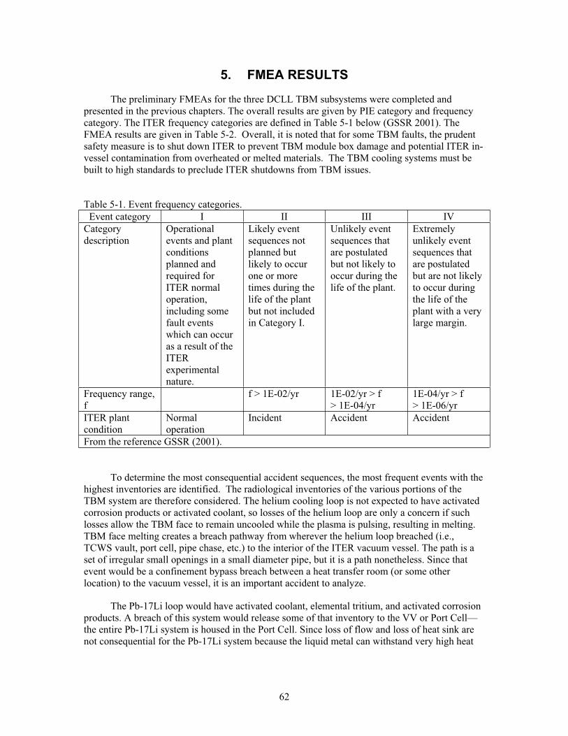
62
5. FMEA RESULTS
The preliminary FMEAs for the three DCLL TBM subsystems were completed and presented in the previous chapters. The overall results are given by PIE category and frequency category. The ITER frequency categories are defined in Table 5-1 below (GSSR 2001). The FMEA results are given in Table 5-2. Overall, it is noted that for some TBM faults, the prudent safety measure is to shut down ITER to prevent TBM module box damage and potential ITER in-vessel contamination from overheated or melted materials. The TBM cooling systems must be built to high standards to preclude ITER shutdowns from TBM issues.
Table 5-1. Event frequency categories. Event category I II III IV
Category description
Operationalevents and plant conditionsplanned and required for ITER normal operation,including some fault events which can occur as a result of the ITERexperimental nature.
Likely event sequences not planned but likely to occur one or more times during the life of the plant but not included in Category I.
Unlikely event sequences that are postulated but not likely to occur during the life of the plant.
Extremely unlikely event sequences that are postulated but are not likely to occur during the life of the plant with a very large margin.
Frequency range, f
f > 1E-02/yr 1E-02/yr > f > 1E-04/yr
1E-04/yr > f > 1E-06/yr
ITER plant condition
Normal operation
Incident Accident Accident
From the reference GSSR (2001).
To determine the most consequential accident sequences, the most frequent events with the highest inventories are identified. The radiological inventories of the various portions of the TBM system are therefore considered. The helium cooling loop is not expected to have activated corrosion products or activated coolant, so losses of the helium loop are only a concern if such losses allow the TBM face to remain uncooled while the plasma is pulsing, resulting in melting. TBM face melting creates a breach pathway from wherever the helium loop breached (i.e., TCWS vault, port cell, pipe chase, etc.) to the interior of the ITER vacuum vessel. The path is a set of irregular small openings in a small diameter pipe, but it is a path nonetheless. Since that event would be a confinement bypass breach between a heat transfer room (or some other location) to the vacuum vessel, it is an important accident to analyze.
The Pb-17Li loop would have activated coolant, elemental tritium, and activated corrosion products. A breach of this system would release some of that inventory to the VV or Port Cell—the entire Pb-17Li system is housed in the Port Cell. Since loss of flow and loss of heat sink are not consequential for the Pb-17Li system because the liquid metal can withstand very high heat
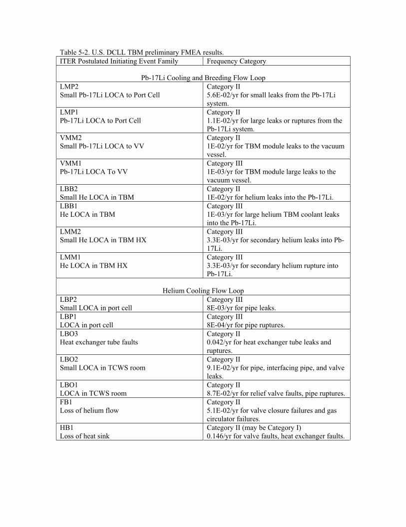
Table 5-2. U.S. DCLL TBM preliminary FMEA results. ITER Postulated Initiating Event Family Frequency Category
Pb-17Li Cooling and Breeding Flow Loop LMP2Small Pb-17Li LOCA to Port Cell
Category II 5.6E-02/yr for small leaks from the Pb-17Li system.
LMP1Pb-17Li LOCA to Port Cell
Category II 1.1E-02/yr for large leaks or ruptures from the Pb-17Li system.
VMM2Small Pb-17Li LOCA to VV
Category II 1E-02/yr for TBM module leaks to the vacuum vessel.
VMM1Pb-17Li LOCA To VV
Category III 1E-03/yr for TBM module large leaks to the vacuum vessel.
LBB2Small He LOCA in TBM
Category II 1E-02/yr for helium leaks into the Pb-17Li.
LBB1He LOCA in TBM
Category III 1E-03/yr for large helium TBM coolant leaks into the Pb-17Li.
LMM2Small He LOCA in TBM HX
Category III 3.3E-03/yr for secondary helium leaks into Pb-17Li.
LMM1He LOCA in TBM HX
Category III 3.3E-03/yr for secondary helium rupture into Pb-17Li.
Helium Cooling Flow Loop LBP2Small LOCA in port cell
Category III 8E-03/yr for pipe leaks.
LBP1LOCA in port cell
Category III 8E-04/yr for pipe ruptures.
LBO3Heat exchanger tube faults
Category II 0.042/yr for heat exchanger tube leaks and ruptures.
LBO2Small LOCA in TCWS room
Category II 9.1E-02/yr for pipe, interfacing pipe, and valve leaks.
LBO1LOCA in TCWS room
Category II 8.7E-02/yr for relief valve faults, pipe ruptures.
FB1Loss of helium flow
Category II 5.1E-02/yr for valve closure failures and gas circulator failures.
HB1Loss of heat sink
Category II (may be Category I) 0.146/yr for valve faults, heat exchanger faults.
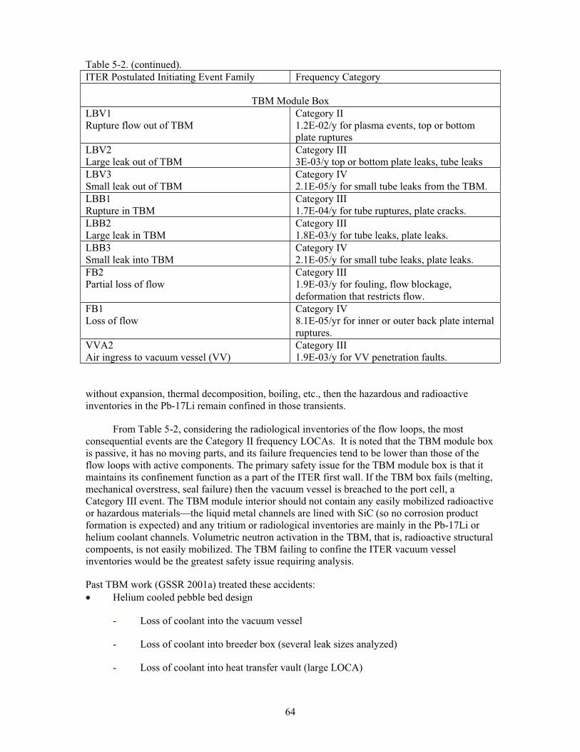
Table 5-2. (continued).
64
ITER Postulated Initiating Event Family Frequency Category
TBM Module Box LBV1Rupture flow out of TBM
Category II 1.2E-02/y for plasma events, top or bottom plate ruptures
LBV2Large leak out of TBM
Category III 3E-03/y top or bottom plate leaks, tube leaks
LBV3Small leak out of TBM
Category IV 2.1E-05/y for small tube leaks from the TBM.
LBB1Rupture in TBM
Category III 1.7E-04/y for tube ruptures, plate cracks.
LBB2Large leak in TBM
Category III 1.8E-03/y for tube leaks, plate leaks.
LBB3Small leak into TBM
Category IV 2.1E-05/y for small tube leaks, plate leaks.
FB2Partial loss of flow
Category III 1.9E-03/y for fouling, flow blockage, deformation that restricts flow.
FB1Loss of flow
Category IV 8.1E-05/yr for inner or outer back plate internal ruptures.
VVA2Air ingress to vacuum vessel (VV)
Category III 1.9E-03/y for VV penetration faults.
without expansion, thermal decomposition, boiling, etc., then the hazardous and radioactive inventories in the Pb-17Li remain confined in those transients.
From Table 5-2, considering the radiological inventories of the flow loops, the most consequential events are the Category II frequency LOCAs. It is noted that the TBM module box is passive, it has no moving parts, and its failure frequencies tend to be lower than those of the flow loops with active components. The primary safety issue for the TBM module box is that it maintains its confinement function as a part of the ITER first wall. If the TBM box fails (melting, mechanical overstress, seal failure) then the vacuum vessel is breached to the port cell, a Category III event. The TBM module interior should not contain any easily mobilized radioactive or hazardous materials—the liquid metal channels are lined with SiC (so no corrosion product formation is expected) and any tritium or radiological inventories are mainly in the Pb-17Li or helium coolant channels. Volumetric neutron activation in the TBM, that is, radioactive structural compoents, is not easily mobilized. The TBM failing to confine the ITER vacuum vessel inventories would be the greatest safety issue requiring analysis.
Past TBM work (GSSR 2001a) treated these accidents: Helium cooled pebble bed design
- Loss of coolant into the vacuum vessel
- Loss of coolant into breeder box (several leak sizes analyzed)
- Loss of coolant into heat transfer vault (large LOCA)
65
Water cooled lithium lead design
- In-vessel loss of coolant accident
- Loss of coolant inside breeder box
- In-vessel and in-TBM LOCA with rupture of First Wall
- Ex-vessel TBM coolant leaks
Water cooled pebble bed design
- In-vessel loss of coolant
- Loss of coolant inside the breeder box
- Ex-vessel TBM coolant leaks
Lithium self-cooled TBM design
- In-vessel loss of coolant, TBM FW break or FW shielding break
- Ex-vessel TBM coolant leaks.
These listed accidents bound the inventory-based safety inspection effort described above. Ex-vessel events can lead to in-vessel overheat and failure, creating a path from the VV to a heat transport room. In-vessel LOCA events can cause intense disruptions that can potentially damage the ITER vessel and lead to further releases. The TBM breaching the VV wall should be examined as well.
Accident analyses already performed in the DDD (Wong 2005) include DCLL TBM coolant leaks – both in-vessel and ex-vessel – which are expected with cooling flow loops, and internal module box leaks as well. The DDD analysis also includes a complete loss of active cooling event. The DDD events envelope these FMEA findings, including VV breach. All the events analyzed have included aggravating failures (e.g., loss of electrical power, damaging plasma disruption) that would not be identified in a FMEA analysis since the FMEA examines individual component failures rather than multiple, simultaneous faults. Therefore, the analyses already performed are more strict than the FMEA findings. For the DCLL TBM, loss of flow or loss of heat sink events occurring to just one of the coolants are not events of great safety concern, since with typical instrumentation and monitoring called out in the design, the TBM event is sensed and the module and/or ITER can be safely shut down. That is, losing helium cooling will overheat the Pb-17Li but overheated liquid metal does not overpressurize or deform the module. Given the thermal excursion effects on the module box, early changeout would be recommended after one of these events. Likewise, losing Pb-17Li cooling is not a safety consequence, the TBM can continue operating with helium coolant available. The loss of coolant events do pose safety concerns, these events will lead to the highest amount of TBM damage and the highest releases into the VV, cell, or TCWS vault. However, as shown in the DDD (Wong 2005), the TBM radiological inventories are small compared to ITER inventories, so TBM releases should be manageable. Breaching the helium coolant system does not overpressurize the building, and any hydrogen generation from first wall water coolant and TBM metal reactions remains below the ITER limit of 2.5 kg.
66
5.1 References
GSSR, 2001. Generic Site Safety Report, Volume X, “Sequence Analysis,” G 84 RI 9 01-06-26 R1.0, International Thermonuclear Experimental Reactor Team, Garching, Germany, June 26, 2001, section X.2.2.2.
GSSR, 2001a. Generic Site Safety Report, Volume VII, “Reference Events,” G 84 RI 6 01-07-10 R1.0, International Thermonuclear Experimental Reactor Team, Garching, Germany, July 10, 2001, Appendix A: Safety Assessment of ITER Test Blanket Modules (TBM).
Wong, 2005. C. P. C. Wong, et al., Design Description Document for the U.S. Dual Coolant Pb-17Li (DCLL) Test Blanket Module, report to the ITER Test Blanket Working Group (TBWG), revision 3, GA-C25027, General Atomics, San Diego, CA, November 15.
67
Appendix A
Preliminary Failure Modes and Effects Analysis for the Pb-17Li Flow Loop
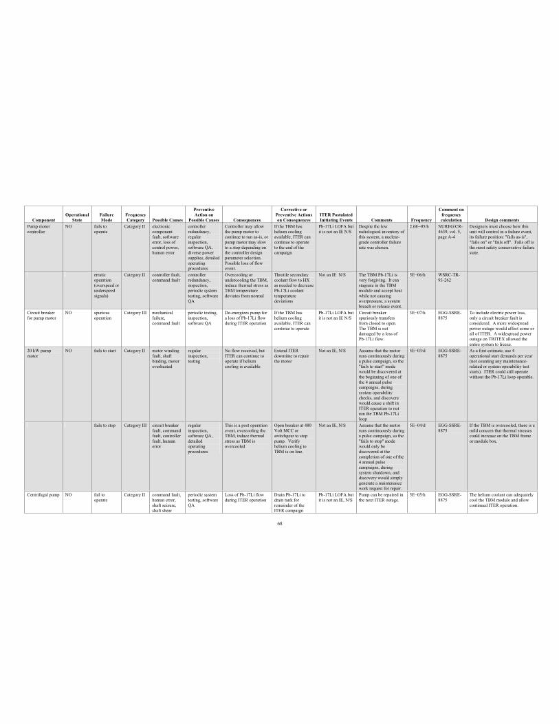
68
Component Operational
StateFailure Mode
Frequency Category Possible Causes
PreventiveAction on
Possible Causes Consequences
Corrective or Preventive Actions on Consequences
ITER Postulated Initiating Events Comments Frequency
Comment on frequency calculation Design comments
Pump motor controller
NO fails to operate
Category II electroniccomponent fault, software error, loss of control power, human error
controller redundancy, regular inspection, software QA, diverse power supplies, detailed operating procedures
Controller may allow the pump motor to continue to run as-is, or pump motor may slow to a stop depending on the controller design parameter selection. Possible loss of flow event.
If the TBM has helium cooling available, ITER can continue to operate to the end of the campaign
Pb-17Li LOFA but it is not an IE N/S
Despite the low radiological inventory of this system, a nuclear-grade controller failure rate was chosen.
2.6E 05/h NUREG/CR-4639, vol. 5, page A-4
Designers must choose how this unit will control in a failure event, its failure position: "fails as-is", "fails on" or "fails off". Fails off is the most safety conservative failure state.
erraticoperation (overspeed or underspeed signals)
Category II controller fault, command fault
controller redundancy, inspection, periodic system testing, software QA
Overcooling or undercooling the TBM, induce thermal stress as TBM temperature deviates from normal
Throttle secondary coolant flow to HX as needed to decrease Pb-17Li coolant temperature deviations
Not an IE N/S The TBM Pb-17Li is very forgiving. It can stagnate in the TBM module and accept heat while not causing overpressure, a system breach or release event.
5E 06/h WSRC-TR-93-262
Circuit breaker for pump motor
NO spurious operation
Category III mechanical failure, command fault
periodic testing, inspection, software QA
De-energizes pump for a loss of Pb-17Li flow during ITER operation
If the TBM has helium cooling available, ITER can continue to operate
Pb-17Li LOFA but it is not an IE N/S
Circuit breaker spuriously transfers from closed to open. The TBM is not damaged by a loss of Pb-17Li flow.
3E 07/h EGG-SSRE-8875
To include electric power loss, only a circuit breaker fault is considered. A more widespread power outage would affect some or all of ITER. A widespread power outage on TRITEX allowed the entire system to freeze.
20 kW pump motor
NO fails to start Category II motor winding fault, shaft binding, motor overheated
regular inspection, testing
No flow received, but ITER can continue to operate if helium cooling is available
Extend ITER downtime to repair the motor
Not an IE, N/S Assume that the motor runs continuously during a pulse campaign, so the "fails to start" mode would be discovered at the beginning of one of the 4 annual pulse campaigns, during system operability checks, and discovery would cause a shift in ITER operation to not run the TBM Pb-17Li loop
5E 03/d EGG-SSRE-8875
As a first estimate, use 4 operational start demands per year (not counting any maintenance-related or system operability test starts). ITER could still operate without the Pb-17Li loop operable.
fails to stop Category III circuit breaker fault, command fault, controller fault, human error
regular inspection, software QA, detailed operating procedures
This is a post operation event, overcooling the TBM, induce thermal stress as TBM is overcooled
Open breaker at 480 Volt MCC or switchgear to stop pump. Verify helium cooling to TBM is on line.
Not an IE, N/S Assume that the motor runs continuously during a pulse campaign, so the "fails to stop" mode would only be discovered at the completion of one of the 4 annual pulse campaigns, during system shutdown, and discovery would simply generate a maintenance work request for repair.
5E 04/d EGG-SSRE-8875
If the TBM is overcooled, there is a mild concern that thermal stresses could increase on the TBM frame or module box.
Centrifugal pump NO fail to operate
Category II command fault, human error, shaft seizure, shaft shear
periodic system testing, software QA
Loss of Pb-17Li flow during ITER operation
Drain Pb-17Li to drain tank for remainder of the ITER campaign
Pb-17Li LOFA but it is not an IE, N/S
Pump can be repaired in the next ITER outage.
5E 05/h EGG-SSRE-8875
The helium coolant can adequately cool the TBM module and allow continued ITER operation.
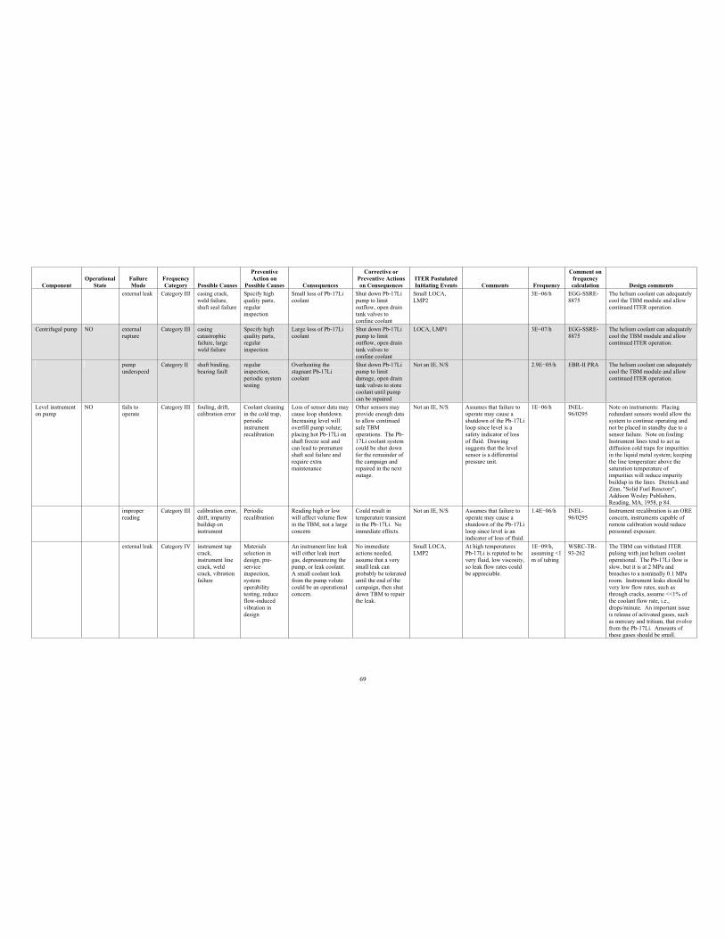
69
Component Operational
StateFailure Mode
Frequency Category Possible Causes
PreventiveAction on
Possible Causes Consequences
Corrective or Preventive Actions on Consequences
ITER Postulated Initiating Events Comments Frequency
Comment on frequency calculation Design comments
external leak Category III casing crack, weld failure, shaft seal failure
Specify high quality parts, regular inspection
Small loss of Pb-17Li coolant
Shut down Pb-17Li pump to limit outflow, open drain tank valves to confine coolant
Small LOCA, LMP2
3E 06/h EGG-SSRE-8875
The helium coolant can adequately cool the TBM module and allow continued ITER operation.
Centrifugal pump NO externalrupture
Category III casingcatastrophicfailure, large weld failure
Specify high quality parts, regular inspection
Large loss of Pb-17Li coolant
Shut down Pb-17Li pump to limit outflow, open drain tank valves to confine coolant
LOCA, LMP1 3E 07/h EGG-SSRE-8875
The helium coolant can adequately cool the TBM module and allow continued ITER operation.
pump underspeed
Category II shaft binding, bearing fault
regular inspection, periodic system testing
Overheating the stagnant Pb-17Li coolant
Shut down Pb-17Li pump to limit damage, open drain tank valves to store coolant until pump can be repaired
Not an IE, N/S 2.9E 05/h EBR-II PRA The helium coolant can adequately cool the TBM module and allow continued ITER operation.
Level instrument on pump
NO fails to operate
Category III fouling, drift, calibration error
Coolant cleaning in the cold trap, periodic instrument recalibration
Loss of sensor data may cause loop shutdown. Increasing level will overfill pump volute; placing hot Pb-17Li on shaft freeze seal and can lead to premature shaft seal failure and require extra maintenance
Other sensors may provide enough data to allow continued safe TBM operations. The Pb-17Li coolant system could be shut down for the remainder of the campaign and repaired in the next outage.
Not an IE, N/S Assumes that failure to operate may cause a shutdown of the Pb-17Li loop since level is a safety indicator of loss of fluid. Drawing suggests that the level sensor is a differential pressure unit.
1E 06/h INEL-96/0295
Note on instruments: Placing redundant sensors would allow the system to continue operating and not be placed in standby due to a sensor failure. Note on fouling: Instrument lines tend to act as diffusion cold traps for impurities in the liquid metal system; keeping the line temperature above the saturation temperature of impurities will reduce impurity buildup in the lines. Dietrich and Zinn, "Solid Fuel Reactors", Addison Wesley Publishers, Reading, MA, 1958, p 84.
improper reading
Category III calibration error, drift, impurity buildup on instrument
Periodicrecalibration
Reading high or low will affect volume flow in the TBM, not a large concern
Could result in temperature transient in the Pb-17Li. No immediate effects.
Not an IE, N/S Assumes that failure to operate may cause a shutdown of the Pb-17Li loop since level is an indicator of loss of fluid.
1.4E 06/h INEL-96/0295
Instrument recalibration is an ORE concern, instruments capable of remote calibration would reduce personnel exposure.
external leak Category IV instrument tap crack,instrument line crack, weld crack, vibration failure
Materials selection in design, pre-serviceinspection, system operability testing, reduce flow-induced vibration in design
An instrument line leak will either leak inert gas, depressurizing the pump, or leak coolant. A small coolant leak from the pump volute could be an operational concern.
No immediate actions needed, assume that a very small leak can probably be tolerated until the end of the campaign, then shut down TBM to repair the leak.
Small LOCA, LMP2
At high temperatures Pb-17Li is reputed to be very fluid, low viscosity, so leak flow rates could be appreciable.
1E 09/h, assuming <1 m of tubing
WSRC-TR-93-262
The TBM can withstand ITER pulsing with just helium coolant operational. The Pb-17Li flow is slow, but it is at 2 MPa and breaches to a nominally 0.1 MPa room. Instrument leaks should be very low flow rates, such as through cracks, assume <<1% of the coolant flow rate, i.e., drops/minute. An important issue is release of activated gases, such as mercury and tritium, that evolve from the Pb-17Li. Amounts of these gases should be small.
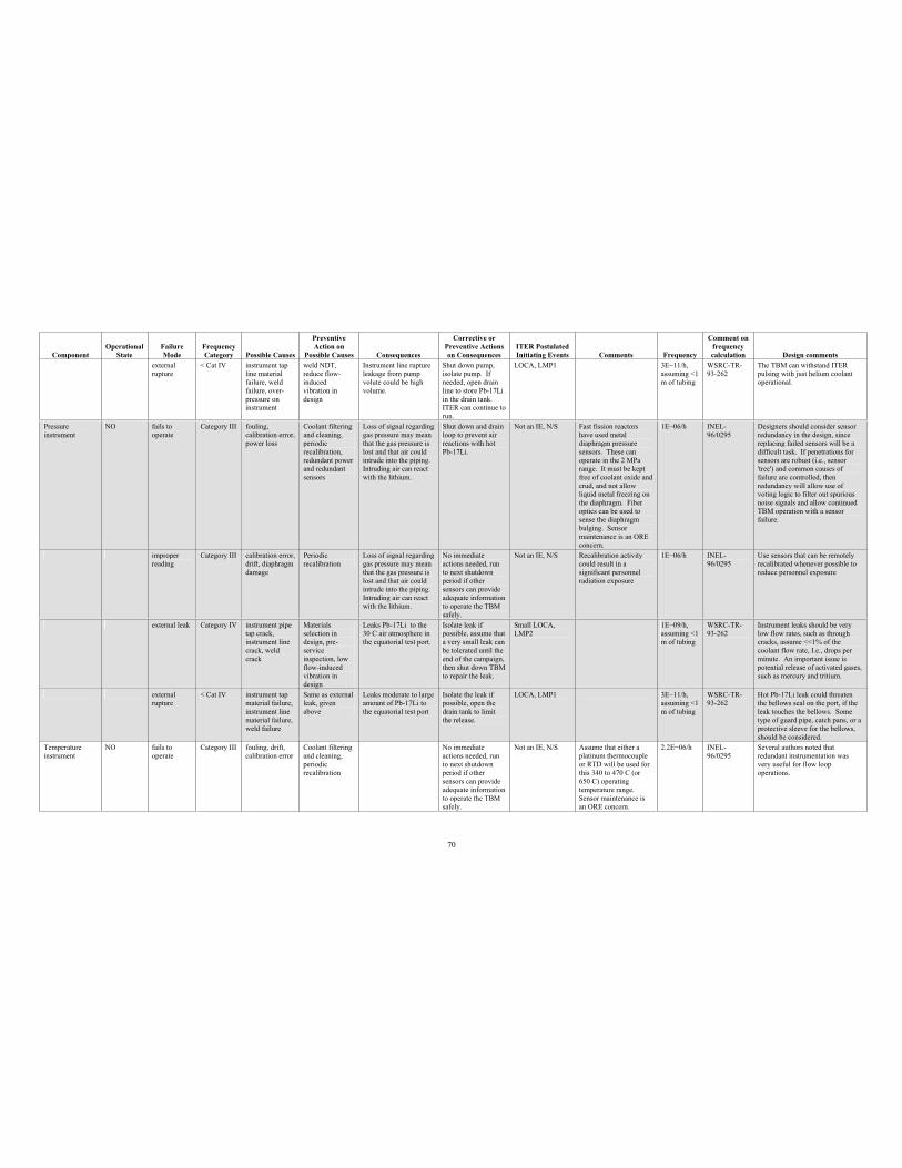
70
Component Operational
StateFailure Mode
Frequency Category Possible Causes
PreventiveAction on
Possible Causes Consequences
Corrective or Preventive Actions on Consequences
ITER Postulated Initiating Events Comments Frequency
Comment on frequency calculation Design comments
external rupture
< Cat IV instrument tap line material failure, weld failure, over-pressure on instrument
weld NDT, reduce flow-inducedvibration in design
Instrument line rupture leakage from pump volute could be high volume.
Shut down pump, isolate pump. If needed, open drain line to store Pb-17Li in the drain tank. ITER can continue to run.
LOCA, LMP1 3E 11/h, assuming <1 m of tubing
WSRC-TR-93-262
The TBM can withstand ITER pulsing with just helium coolant operational.
Pressure instrument
NO fails to operate
Category III fouling, calibration error, power loss
Coolant filtering and cleaning, periodic recalibration, redundant power and redundant sensors
Loss of signal regarding gas pressure may mean that the gas pressure is lost and that air could intrude into the piping. Intruding air can react with the lithium.
Shut down and drain loop to prevent air reactions with hot Pb-17Li.
Not an IE, N/S Fast fission reactors have used metal diaphragm pressure sensors. These can operate in the 2 MPa range. It must be kept free of coolant oxide and crud, and not allow liquid metal freezing on the diaphragm. Fiber optics can be used to sense the diaphragm bulging. Sensor maintenance is an ORE concern.
1E 06/h INEL-96/0295
Designers should consider sensor redundancy in the design, since replacing failed sensors will be a difficult task. If penetrations for sensors are robust (i.e., sensor 'tree') and common causes of failure are controlled, then redundancy will allow use of voting logic to filter out spurious noise signals and allow continued TBM operation with a sensor failure.
improper reading
Category III calibration error, drift, diaphragm damage
Periodicrecalibration
Loss of signal regarding gas pressure may mean that the gas pressure is lost and that air could intrude into the piping. Intruding air can react with the lithium.
No immediate actions needed, run to next shutdown period if other sensors can provide adequate information to operate the TBM safely.
Not an IE, N/S Recalibration activity could result in a significant personnel radiation exposure
1E 06/h INEL-96/0295
Use sensors that can be remotely recalibrated whenever possible to reduce personnel exposure
external leak Category IV instrument pipe tap crack, instrument line crack, weld crack
Materials selection in design, pre-serviceinspection, low flow-induced vibration in design
Leaks Pb-17Li to the 30 C air atmosphere in the equatorial test port.
Isolate leak if possible, assume that a very small leak can be tolerated until the end of the campaign, then shut down TBM to repair the leak.
Small LOCA, LMP2
1E 09/h, assuming <1 m of tubing
WSRC-TR-93-262
Instrument leaks should be very low flow rates, such as through cracks, assume <<1% of the coolant flow rate, I.e., drops per minute. An important issue is potential release of activated gases, such as mercury and tritium.
externalrupture
< Cat IV instrument tap material failure, instrument line material failure, weld failure
Same as external leak, given above
Leaks moderate to large amount of Pb-17Li to the equatorial test port
Isolate the leak if possible, open the drain tank to limit the release.
LOCA, LMP1 3E 11/h, assuming <1 m of tubing
WSRC-TR-93-262
Hot Pb-17Li leak could threaten the bellows seal on the port, if the leak touches the bellows. Some type of guard pipe, catch pans, or a protective sleeve for the bellows, should be considered.
Temperature instrument
NO fails to operate
Category III fouling, drift, calibration error
Coolant filtering and cleaning, periodic recalibration
No immediate actions needed, run to next shutdown period if other sensors can provide adequate information to operate the TBM safely.
Not an IE, N/S Assume that either a platinum thermocouple or RTD will be used for this 340 to 470 C (or 650 C) operating temperature range. Sensor maintenance is an ORE concern.
2.2E 06/h INEL-96/0295
Several authors noted that redundant instrumentation was very useful for flow loop operations.
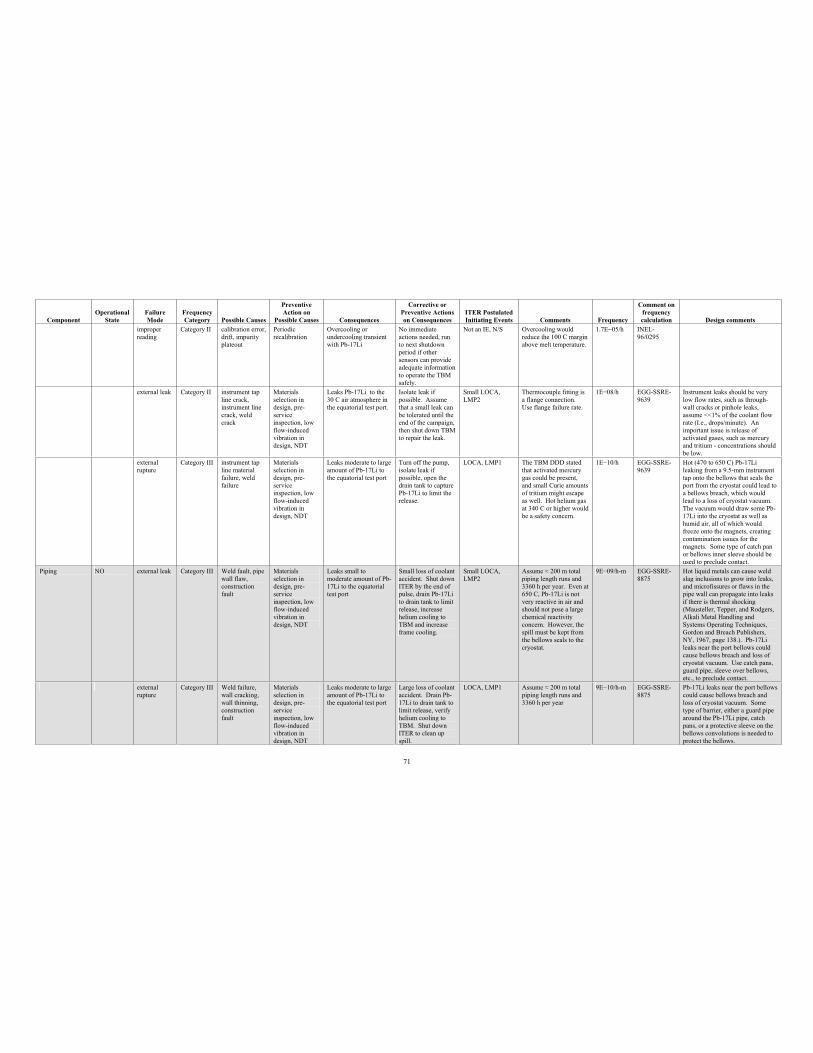
71
Component Operational
StateFailure Mode
Frequency Category Possible Causes
PreventiveAction on
Possible Causes Consequences
Corrective or Preventive Actions on Consequences
ITER Postulated Initiating Events Comments Frequency
Comment on frequency calculation Design comments
improper reading
Category II calibration error, drift, impurity plateout
Periodicrecalibration
Overcooling or undercooling transient with Pb-17Li
No immediate actions needed, run to next shutdown period if other sensors can provide adequate information to operate the TBM safely.
Not an IE, N/S Overcooling would reduce the 100 C margin above melt temperature.
1.7E 05/h INEL-96/0295
external leak Category II instrument tap line crack, instrument line crack, weld crack
Materials selection in design, pre-serviceinspection, low flow-induced vibration in design, NDT
Leaks Pb-17Li to the 30 C air atmosphere in the equatorial test port.
Isolate leak if possible. Assume that a small leak can be tolerated until the end of the campaign, then shut down TBM to repair the leak.
Small LOCA, LMP2
Thermocouple fitting is a flange connection. Use flange failure rate.
1E 08/h EGG-SSRE-9639
Instrument leaks should be very low flow rates, such as through-wall cracks or pinhole leaks, assume <<1% of the coolant flow rate (I.e., drops/minute). An important issue is release of activated gases, such as mercury and tritium - concentrations should be low.
external rupture
Category III instrument tap line material failure, weld failure
Materials selection in design, pre-serviceinspection, low flow-induced vibration in design, NDT
Leaks moderate to large amount of Pb-17Li to the equatorial test port
Turn off the pump, isolate leak if possible, open the drain tank to capture Pb-17Li to limit the release.
LOCA, LMP1 The TBM DDD stated that activated mercury gas could be present, and small Curie amounts of tritium might escape as well. Hot helium gas at 340 C or higher would be a safety concern.
1E 10/h EGG-SSRE-9639
Hot (470 to 650 C) Pb-17Li leaking from a 9.5-mm instrument tap onto the bellows that seals the port from the cryostat could lead to a bellows breach, which would lead to a loss of cryostat vacuum. The vacuum would draw some Pb-17Li into the cryostat as well as humid air, all of which would freeze onto the magnets, creating contamination issues for the magnets. Some type of catch pan or bellows inner sleeve should be used to preclude contact.
Piping NO external leak Category III Weld fault, pipe wall flaw, construction fault
Materials selection in design, pre-serviceinspection, low flow-induced vibration in design, NDT
Leaks small to moderate amount of Pb-17Li to the equatorial test port
Small loss of coolant accident. Shut down ITER by the end of pulse, drain Pb-17Li to drain tank to limit release, increase helium cooling to TBM and increase frame cooling.
Small LOCA, LMP2
Assume 200 m total piping length runs and 3360 h per year. Even at 650 C, Pb-17Li is not very reactive in air and should not pose a large chemical reactivity concern. However, the spill must be kept from the bellows seals to the cryostat.
9E 09/h-m EGG-SSRE-8875
Hot liquid metals can cause weld slag inclusions to grow into leaks, and microfissures or flaws in the pipe wall can propagate into leaks if there is thermal shocking (Mausteller, Tepper, and Rodgers, Alkali Metal Handling and Systems Operating Techniques, Gordon and Breach Publishers, NY, 1967, page 138.). Pb-17Li leaks near the port bellows could cause bellows breach and loss of cryostat vacuum. Use catch pans, guard pipe, sleeve over bellows, etc., to preclude contact.
externalrupture
Category III Weld failure, wall cracking, wall thinning, construction fault
Materials selection in design, pre-serviceinspection, low flow-induced vibration in design, NDT
Leaks moderate to large amount of Pb-17Li to the equatorial test port
Large loss of coolant accident. Drain Pb-17Li to drain tank to limit release, verify helium cooling to TBM. Shut down ITER to clean up spill.
LOCA, LMP1 Assume 200 m total piping length runs and 3360 h per year
9E 10/h-m EGG-SSRE-8875
Pb-17Li leaks near the port bellows could cause bellows breach and loss of cryostat vacuum. Some type of barrier, either a guard pipe around the Pb-17Li pipe, catch pans, or a protective sleeve on the bellows convolutions is needed to protect the bellows.
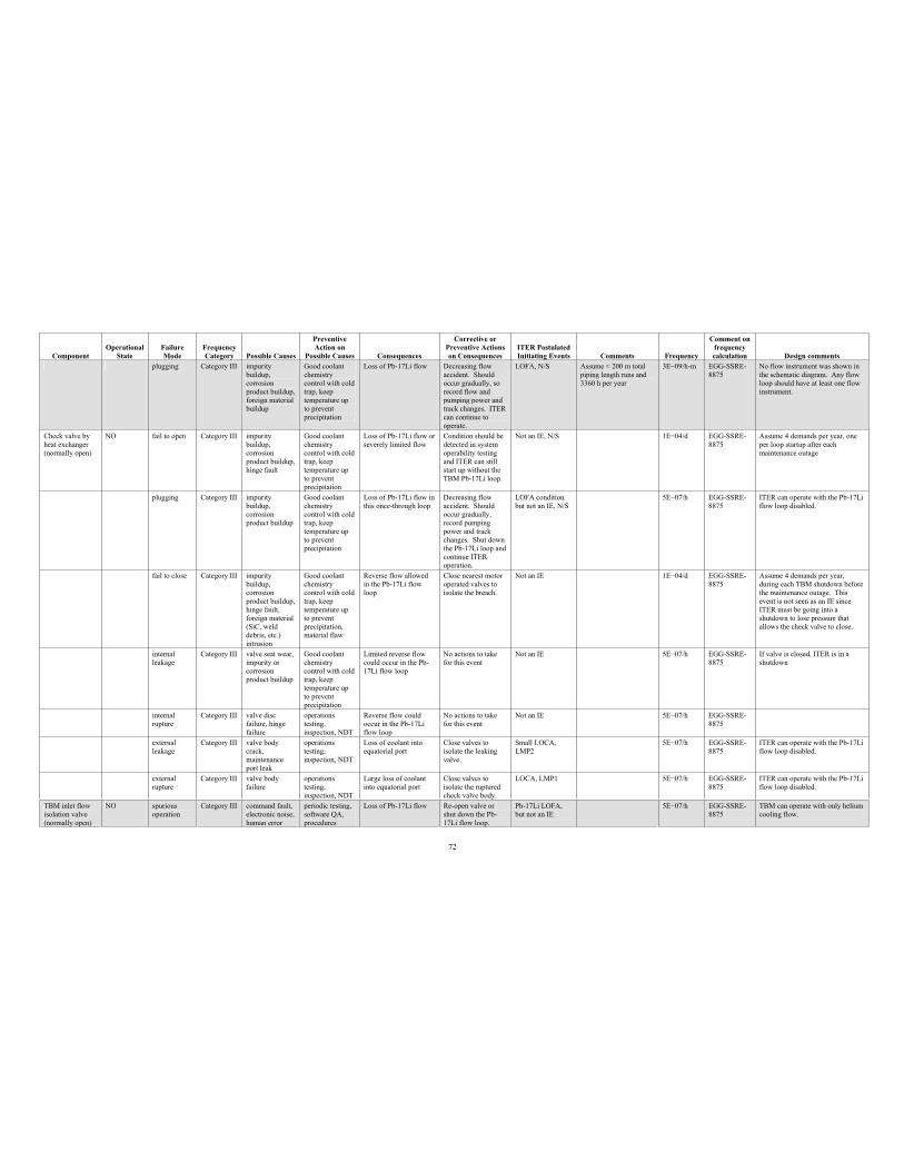
72
Component Operational
StateFailure Mode
Frequency Category Possible Causes
PreventiveAction on
Possible Causes Consequences
Corrective or Preventive Actions on Consequences
ITER Postulated Initiating Events Comments Frequency
Comment on frequency calculation Design comments
plugging Category III impurity buildup, corrosionproduct buildup, foreign material buildup
Good coolant chemistry control with cold trap, keep temperature up to prevent precipitation
Loss of Pb-17Li flow Decreasing flow accident. Should occur gradually, so record flow and pumping power and track changes. ITER can continue to operate.
LOFA, N/S Assume 200 m total piping length runs and 3360 h per year
3E 09/h-m EGG-SSRE-8875
No flow instrument was shown in the schematic diagram. Any flow loop should have at least one flow instrument.
Check valve by heat exchanger (normally open)
NO fail to open Category III impurity buildup, corrosionproduct buildup, hinge fault
Good coolant chemistry control with cold trap, keep temperature up to prevent precipitation
Loss of Pb-17Li flow or severely limited flow
Condition should be detected in system operability testing and ITER can still start up without the TBM Pb-17Li loop.
Not an IE, N/S 1E 04/d EGG-SSRE-8875
Assume 4 demands per year, one per loop startup after each maintenance outage
plugging Category III impurity buildup, corrosionproduct buildup
Good coolant chemistry control with cold trap, keep temperature up to prevent precipitation
Loss of Pb-17Li flow in this once-through loop
Decreasing flow accident. Should occur gradually, record pumping power and track changes. Shut down the Pb-17Li loop and continue ITER operation.
LOFA condition but not an IE, N/S
5E 07/h EGG-SSRE-8875
ITER can operate with the Pb-17Li flow loop disabled.
fail to close Category III impurity buildup, corrosionproduct buildup, hinge fault, foreign material (SiC, weld debris, etc.) intrusion
Good coolant chemistry control with cold trap, keep temperature up to prevent precipitation, material flaw
Reverse flow allowed in the Pb-17Li flow loop
Close nearest motor operated valves to isolate the breach.
Not an IE 1E 04/d EGG-SSRE-8875
Assume 4 demands per year, during each TBM shutdown before the maintenance outage. This event is not seen as an IE since ITER must be going into a shutdown to lose pressure that allows the check valve to close.
internal leakage
Category III valve seat wear, impurity or corrosionproduct buildup
Good coolant chemistry control with cold trap, keep temperature up to prevent precipitation
Limited reverse flow could occur in the Pb-17Li flow loop
No actions to take for this event
Not an IE 5E 07/h EGG-SSRE-8875
If valve is closed, ITER is in a shutdown
internal rupture
Category III valve disc failure, hinge failure
operations testing, inspection, NDT
Reverse flow could occur in the Pb-17Li flow loop
No actions to take for this event
Not an IE 5E 07/h EGG-SSRE-8875
external leakage
Category III valve body crack,maintenance port leak
operations testing, inspection, NDT
Loss of coolant into equatorial port
Close valves to isolate the leaking valve.
Small LOCA, LMP2
5E 07/h EGG-SSRE-8875
ITER can operate with the Pb-17Li flow loop disabled.
external rupture
Category III valve body failure
operations testing, inspection, NDT
Large loss of coolant into equatorial port
Close valves to isolate the ruptured check valve body.
LOCA, LMP1 5E 07/h EGG-SSRE-8875
ITER can operate with the Pb-17Li flow loop disabled.
TBM inlet flow isolation valve (normally open)
NO spuriousoperation
Category III command fault, electronic noise, human error
periodic testing, software QA, procedures
Loss of Pb-17Li flow Re-open valve or shut down the Pb-17Li flow loop.
Pb-17Li LOFA, but not an IE
5E 07/h EGG-SSRE-8875
TBM can operate with only helium cooling flow.
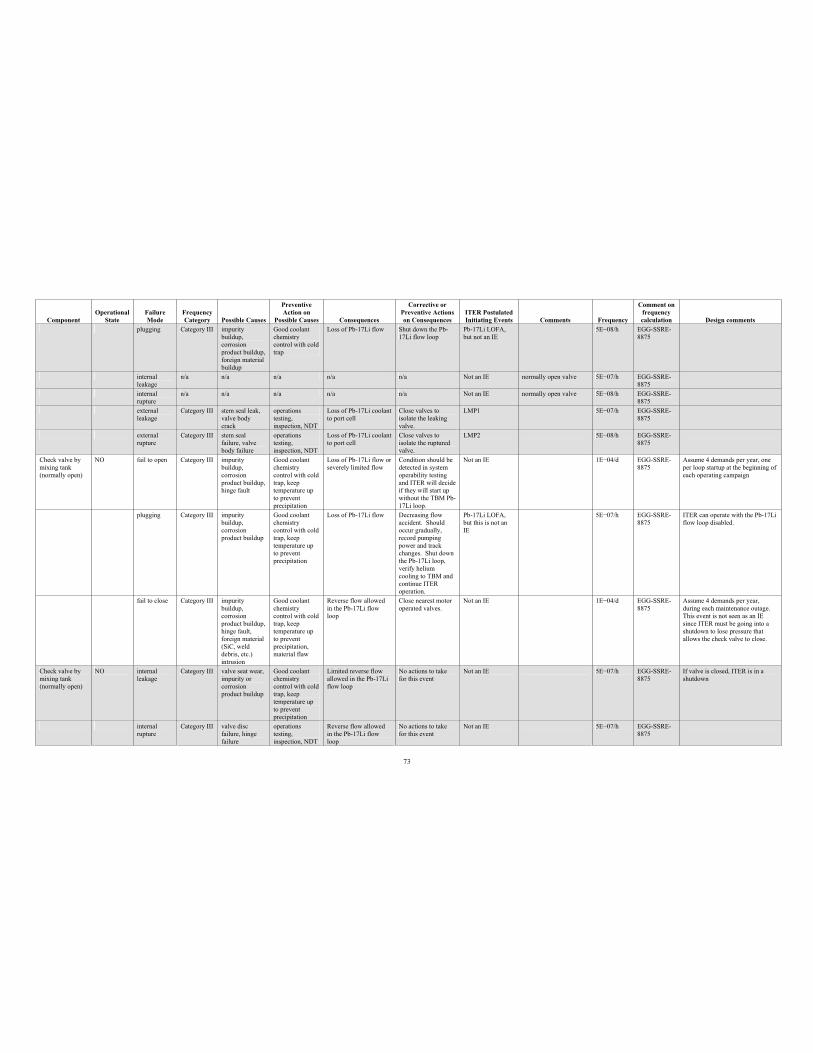
73
Component Operational
StateFailure Mode
Frequency Category Possible Causes
PreventiveAction on
Possible Causes Consequences
Corrective or Preventive Actions on Consequences
ITER Postulated Initiating Events Comments Frequency
Comment on frequency calculation Design comments
plugging Category III impurity buildup, corrosionproduct buildup, foreign material buildup
Good coolant chemistry control with cold trap
Loss of Pb-17Li flow Shut down the Pb-17Li flow loop
Pb-17Li LOFA, but not an IE
5E 08/h EGG-SSRE-8875
internal leakage
n/a n/a n/a n/a n/a Not an IE normally open valve 5E 07/h EGG-SSRE-8875
internal rupture
n/a n/a n/a n/a n/a Not an IE normally open valve 5E 08/h EGG-SSRE-8875
externalleakage
Category III stem seal leak, valve body crack
operations testing, inspection, NDT
Loss of Pb-17Li coolant to port cell
Close valves to isolate the leaking valve.
LMP1 5E 07/h EGG-SSRE-8875
externalrupture
Category III stem seal failure, valve body failure
operations testing, inspection, NDT
Loss of Pb-17Li coolant to port cell
Close valves to isolate the ruptured valve.
LMP2 5E 08/h EGG-SSRE-8875
Check valve by mixing tank (normally open)
NO fail to open Category III impurity buildup, corrosionproduct buildup, hinge fault
Good coolant chemistry control with cold trap, keep temperature up to prevent precipitation
Loss of Pb-17Li flow or severely limited flow
Condition should be detected in system operability testing and ITER will decide if they will start up without the TBM Pb-17Li loop.
Not an IE 1E 04/d EGG-SSRE-8875
Assume 4 demands per year, one per loop startup at the beginning of each operating campaign
plugging Category III impurity buildup, corrosionproduct buildup
Good coolant chemistry control with cold trap, keep temperature up to prevent precipitation
Loss of Pb-17Li flow Decreasing flow accident. Should occur gradually, record pumping power and track changes. Shut down the Pb-17Li loop, verify helium cooling to TBM and continue ITER operation.
Pb-17Li LOFA, but this is not an IE
5E 07/h EGG-SSRE-8875
ITER can operate with the Pb-17Li flow loop disabled.
fail to close Category III impurity buildup, corrosionproduct buildup, hinge fault, foreign material (SiC, weld debris, etc.) intrusion
Good coolant chemistry control with cold trap, keep temperature up to prevent precipitation, material flaw
Reverse flow allowed in the Pb-17Li flow loop
Close nearest motor operated valves.
Not an IE 1E 04/d EGG-SSRE-8875
Assume 4 demands per year, during each maintenance outage. This event is not seen as an IE since ITER must be going into a shutdown to lose pressure that allows the check valve to close.
Check valve by mixing tank (normally open)
NO internal leakage
Category III valve seat wear, impurity or corrosionproduct buildup
Good coolant chemistry control with cold trap, keep temperature up to prevent precipitation
Limited reverse flow allowed in the Pb-17Li flow loop
No actions to take for this event
Not an IE 5E 07/h EGG-SSRE-8875
If valve is closed, ITER is in a shutdown
internal rupture
Category III valve disc failure, hinge failure
operations testing, inspection, NDT
Reverse flow allowed in the Pb-17Li flow loop
No actions to take for this event
Not an IE 5E 07/h EGG-SSRE-8875
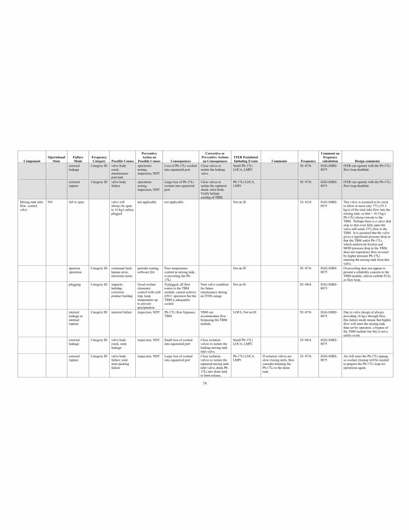
74
Component Operational
StateFailure Mode
Frequency Category Possible Causes
PreventiveAction on
Possible Causes Consequences
Corrective or Preventive Actions on Consequences
ITER Postulated Initiating Events Comments Frequency
Comment on frequency calculation Design comments
externalleakage
Category III valve body crack,maintenance port leak
operations testing, inspection, NDT
Loss of Pb-17Li coolant into equatorial port
Close valves to isolate the leaking valve.
Small Pb-17Li LOCA, LMP2
5E 07/h EGG-SSRE-8875
ITER can operate with the Pb-17Li flow loop disabled.
externalrupture
Category III valve body failure
operations testing, inspection, NDT
Large loss of Pb-17Li coolant into equatorial port
Close valves to isolate the ruptured check valve body. Verify helium cooling of TBM.
Pb-17Li LOCA, LMP1
5E 07/h EGG-SSRE-8875
ITER can operate with the Pb-17Li flow loop disabled.
Mixing tank inlet flow control valve
NO fail to open valve will always be open to 16 kg/s unless plugged
not applicable not applicable Not an IE 1E 03/d EGG-SSRE-8875
This valve is assumed to be sized to allow at most only 77% (55.5 kg/s) of the total inlet flow into the mixing tank, so that 16.5 kg/s Pb-17Li always travels to the TBM. Perhaps there is a valve disk stop so that even fully open the valve still sends 23% flow to the TBM. It is assumed that the valve gives a significant pressure drop so that the TBM outlet Pb-17Li, which underwent friction and MHD pressure drop in the TBM, does not experience flow reversal by higher pressure Pb-17Li entering the mixing tank from this valve.
spurious operation
Category III command fault, human error, electronic noise
periodic testing, software QA
Poor temperature control in mixing tank, overcooling the Pb-17Li
Not an IE 3E 07/h EGG-SSRE-8875
Overcooling does not appear to present a reliability concern to the TBM module, silicon carbide FCIs, or flow loop.
plugging Category III impurity buildup, corrosionproduct buildup
Good coolant chemistry control with cold trap, keep temperature up to prevent precipitation
If plugged, all flow routes to the TBM module, cannot achieve 650 C operation but the TBM is adequately cooled
Note valve condition for future maintenance during an ITER outage
Not an IE 5E 08/h EGG-SSRE-8875
internal leakage or internal rupture
Category III material failure inspection, NDT Pb-17Li flow bypasses TBM
TBM can accommodate flow bypassing the TBM module
LOFA, Not an IE 5E 07/h EGG-SSRE-8875
Due to valve design of always providing 16 kg/s through flow, this failure mode means that higher flow will enter the mixing tank than set by operators, a bypass of the TBM module but this is not a safety event.
external leakage
Category III valve body crack, stem leakage
inspection, NDT Small loss of coolant into equatorial port
Close isolation valves to isolate the leaking mixing tank inlet valve.
Small Pb-17Li LOCA, LMP2
1E 06/h EGG-SSRE-8875
external rupture
Category III valve body failure, total stem packing failure
inspection, NDT Large loss of coolant into equatorial port
Close isolation valves to isolate the ruptured mixing tank inlet valve, drain Pb-17Li into drain tank to limit release.
Pb-17Li LOCA, LMP1
If isolation valves are slow closing units, then consider draining the Pb-17Li to the drain tank.
1E 07/h EGG-SSRE-8875
Air will enter the Pb-17Li piping, so coolant cleanup will be needed to prepare the Pb-17Li loop for operations again.
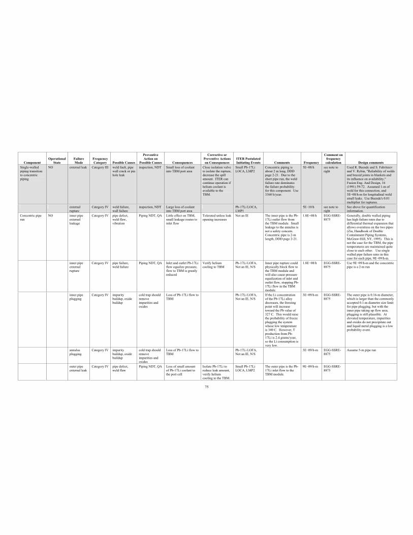
75
Component Operational
StateFailure Mode
Frequency Category Possible Causes
PreventiveAction on
Possible Causes Consequences
Corrective or Preventive Actions on Consequences
ITER Postulated Initiating Events Comments Frequency
Comment on frequency calculation Design comments
Single-walled piping transition to concentric piping
NO external leak Category III weld fault, pipe wall crack or pin hole leak
inspection, NDT Small loss of coolant into TBM port area
Close isolation valve to isolate the rupture, decrease the spill amount. ITER can continue operation if helium coolant is available to the TBM.
Small Pb-17Li LOCA, LMP2
Concentric piping is about 2 m long, DDD page 2-21. Due to the short pipe run, the weld failure rate dominates the failure probability for this component. Use 3360 h/year.
5E 08/h see note to right
Used R. Buende and S. Fabritsiev and V. Rybin, "Reliability of welds and brazed joints in blankets and its influence on availability," Fusion Eng. And Design, 16 (1991) 59-72. Assumed 1-m of weld for this connection, and 5E 08/h-m for longitudinal weld small leaks. Use Buende's 0.01 multiplier for ruptures.
externalrupture
Category IV weld failure, wall failure
inspection, NDT Large loss of coolant into TBM port area
Pb-17Li LOCA, LMP1
5E 10/h see note to right
See above for quantification information.
Concentric pipe run
NO inner pipe externalleakage
Category IV pipe defect, weld flaw, vibration
Piping NDT, QA Little effect on TBM, small leakage routes to inlet flow
Tolerated unless leak opening increases
Not an IE The inner pipe is the Pb-17Li outlet flow from the TBM module. Small leakage to the annulus is not a safety concern. Concentric pipe is 2-m length, DDD page 2-21.
1.8E 08/h EGG-SSRE-8875
Generally, double walled piping has high failure rates due to differential thermal expansion that allows overstress on the two pipes (Ziu, Handbook of Double Containment Piping Systems, McGraw-Hill, NY, 1995). This is not the case for the TBM, the pipe temperatures are maintained quite close to each other. Use single walled pipe failure rates in this case for each pipe, 9E 09/h-m.
inner pipe externalrupture
Category IV pipe failure, weld failure
Piping NDT, QA Inlet and outlet Pb-17Li flow equalize pressure, flow to TBM is greatly reduced
Verify helium cooling to TBM
Pb-17Li LOFA, Not an IE, N/S
Inner pipe rupture could physically block flow to the TBM module and will also cause pressure equalization of inlet and outlet flow, stopping Pb-17Li flow in the TBM module.
1.8E 08/h EGG-SSRE-8875
Use 9E 09/h-m and the concentric pipe is a 2-m run
inner pipe plugging
Category IV impurity buildup, oxide buildup
cold trap should remove impurities and oxides
Loss of Pb-17Li flow to TBM
Pb-17Li LOFA, Not an IE, N/S
If the Li concentration of the Pb-17Li alloy decreases, the freezing point will increase toward the Pb value of 327 C. This would raise the probability of freeze plugging the system whose low temperature is 340 C. However, T production from Pb-17Li is 2.4 grams/year, so the Li consumption is very low.
3E 09/h-m EGG-SSRE-8875
The outer pipe is 0.16-m diameter, which is larger than the commonly accepted 0.1-m diameter size limit for pipe plugging, but with the inner pipe taking up flow area, plugging is still plausible. At elevated temperature, impurities and oxides do not precipitate out and liquid metal plugging is a low probability event.
annulus plugging
Category IV impurity buildup, oxide buildup
cold trap should remove impurities and oxides
Loss of Pb-17Li flow to TBM
Pb-17Li LOFA, Not an IE, N/S
3E 09/h-m EGG-SSRE-8875
Assume 5-m pipe run
outer pipe external leak
Category IV pipe defect, weld flaw
Piping NDT, QA Loss of small amount of Pb-17Li coolant to the port cell
Isolate Pb-17Li to reduce leak amount, verify helium cooling to the TBM.
Small Pb-17Li LOCA, LMP2
The outer pipe is the Pb-17Li inlet flow to the TBM module.
9E 09/h-m EGG-SSRE-8875
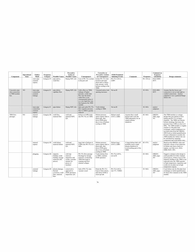
76
Component Operational
StateFailure Mode
Frequency Category Possible Causes
PreventiveAction on
Possible Causes Consequences
Corrective or Preventive Actions on Consequences
ITER Postulated Initiating Events Comments Frequency
Comment on frequency calculation Design comments
outer pipe externalrupture
Category IV pipe defect, weld flaw
Piping NDT, QA Loss of Pb-17Li coolant to the port cell
Isolate Pb-17Li leak location and open drain tank to reduce leak amount, verify helium cooling to the TBM.
Pb-17Li LOCA, LMP1
9E 10/h-m EGG-SSRE-8875
Concentric pipe inlet connection to TBM module box
NO inner pipe connectionexternalleakage
Category II pipe defect, capillary flow
Piping NDT, QA Little effect on TBM, leakage of higher pressure, cooler inlet flow into the hotter outlet flow is not consequential unless it is a very high flow rate that bypasses the TBM module
Tolerated unless leak opening increases
Not an IE 3E 05/h EGG-SRE-8875
Assume that the freeze seal connection is not as leak tight as welded connections. Analyst judgment to use a gasketed flange failure rate.
inner pipe connectionexternalrupture
Category II pipe failure Piping NDT, QA Inlet and outlet Pb-17Li flow equalize pressure, flow to TBM is greatly reduced
Verify helium cooling to TBM
Not an IE 3E 06/h analystjudgment
TBM flow passages
NO internal leakage
Category III weld flaw, material flaw
weld and material NDT, QA
helium at 8 MPa leaks into Pb-17Li at 2 MPa
Helium pressure opens rupture disk to drain tank, shut down ITER pulse due to loss of helium cooling in TBM
Helium small LOCA, LBB2
Assume that a small helium leak cools the TBM adequately for an orderly plasma shutdown.
4E 06/h OREDA 2002, page 387
The TBM module is a unique design that uses helium in flow tubing and Pb-17Li in larger channels. The TBM can tolerate helium inleakage that raises the pressure from 2 MPa to close to 8 MPa. The TBM module is roughly similar to a flat plate heat exchanger; analyst judgment is to use those data from the OREDA 2002 book as initial quantification. If more refinement is needed, the TBM module box failure rate can be calculated by summing component and weld failure rates.
internal rupture
Category III weld failure, material failure
weld and material NDT, QA
large leak of helium at 8 MPa into Pb-17Li at 2 MPa
Helium pressure opens rupture disk to drain tank, shut down ITER pulse due to loss of helium cooling in TBM
Helium large LOCA, LBB1
A large helium leak will probably need a rapid plasma shutdown to avoid melting part of the TBM.
4E 07/h analyst judgment
Based on the OREDA value and typically a factor of ten reduction in failure rate from a leak to a rupture, see Eide et al., EGG-SSRE-9639, 1991.
plugging Category III impurity buildup, oxide buildup, foreign materials (SiC pieces)
cold trap removes impurities and oxides, consider strainer for pieces of insulator
Pb-17Li flow passage blockage by foreign material; overheating TBM that leads to warping and flow channel collapse
Verify helium flow to TBM, continue ITER operation
Pb-17Li LOFA, not an IE
2E 06/h OREDA 2002, page 387
Suggest a strainer in the design to catch possible FCI (flow channel insert) pieces, if these were to fail. Impurity buildup in the TBM is not expected since the TBM operates at high temperature; impurities and oxides do not plate out in high temperature regions.
external leakage
Category III plasma damage, thermal overstress, weld flaw, material flaw
conservativeapproach to ITER operation; inspection, QA
leak of Pb-17Li into vacuum vessel
Drain the Pb-17Li loop to limit release, shut down ITER to clean up leak
Pb-17Li LOCA into VV, VMM2
3E 06/h OREDA 2002, page 387
Used failure rate for flat plate heat exchanger as initial quantification for these flow channels in the TBM module
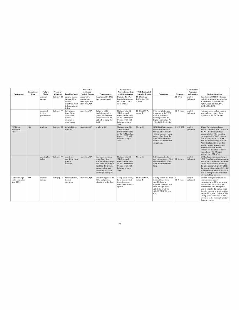
77
Component Operational
StateFailure Mode
Frequency Category Possible Causes
PreventiveAction on
Possible Causes Consequences
Corrective or Preventive Actions on Consequences
ITER Postulated Initiating Events Comments Frequency
Comment on frequency calculation Design comments
external rupture
Category III extreme plasma damage, high thermal overstress, weld failure, material failure
conservativeapproach to ITER operation, inspection, QA
large leak of Pb-17Li into vacuum vessel
Drain the Pb-17Li loop to limit release, shut down ITER to clean up leak
Pb-17Li large LOCA into VV, VMM1
3E 07/h analyst judgment
Based on the OREDA value and typically a factor of ten reduction in failure rate from a leak to a rupture, see Eide et al., EGG-SSRE-9639, 1991.
increased friction pressure drop
Category IV flow channel insert failure due to flow inducedvibration or other causes
inspection, QA failure of MHD insulating panel or panels, MHD forces increase on Pb-17Li, difficult to pump the fluid
Shut down the Pb-17Li loop until repairs can be made on the TBM module. Operate ITER with helium cooling to TBM.
Pb-17Li LOFA, not an IE
FCIs provide thermal insulation to the TBM module and to the helium gas from the higher temperature Pb-17Li (DDD 2.2.1.1.4).
1E 04/year analyst judgment
Judgment based on SiC ceramic heat exchanger tubes. Basis explained in the FMEA text.
TBM flow passage SiC plates
NO cracking Category III included flaws, vibration
inspection, QA cracks in SiC Shut down the Pb-17Li loop until repairs can be made on the TBM module. Operate ITER with helium cooling to TBM.
Not an IE If MHD effects increase, cannot flow Pb-17Li through TBM module without excessive pump power. Shut down the Pb-17Li loop until the module can be repaired or replaced.
1.32E 07/h analystjudgment
Silicon Carbide is used as an insulator to reduce MHD effects in the Pb-17Li flowing in high magnetic fields. The operating environment is 700C, 10 cm/s flow of heavy metal in the SiC, with irradiation damage over time. Analyst judgment is to use SiC insulator values for cracking as loss of mechanical integrity, estimate 4 insulators to a flow channel and 3.3E 08/h per insulator, or 1.32E 07/h
catastrophicfailure
Category IV overstress, subcritical crack growth, vibration
inspection, QA SiC pieces separate, enter flow. If no strainer is in the design, shut down the pump to limit SiC debris in the system and protect pump impeller, heat exchanger tubing, etc.
Shut down the Pb-17Li loop until repairs can be made on the TBM module. Operate ITER with helium cooling to TBM.
Not an IE SiC pieces in the flow can cause damage. Shut down the Pb-17Li flow loop, drain to the drain tank
<1E 04/year
analystjudgment
SiC has been used successfully in 1,200 C applications in combustion turbine rotors and stators, with over 30,000 hours lifetime. Reducing the temperature will greatly add to the service lifetime of the SiC. SiC is also radiation resistant since it is used as an impervious fission fuel pebble cladding material.
Concentric pipe outlet connection from TBM
NO external rupture
Category IV Material failure, thermal overstress
inspection, QA inlet flow bypasses the TBM and proceeds directly to outlet flow.
Verify TBM cooling by helium and that frame is cooled. ITER can continue to operate.
Pb-17Li LOFA, not an IE
Sliding seal for the inner tube outflow. Some small leakage is expected cross this seal from the high P cold side to the low P hot side (TBM DDD, page C-4)
<1E 04/year
analystjudgment
External leakage is expected and small amounts are not consequential to TBM operations, so there is no external leakage failure mode. The inner pipe is held in place by the applied force from the concentric pipe transition and the TBM joint. Failure of this sliding seal is considered to be a low value in the extremely unlikely frequency range.
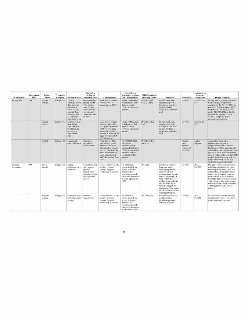
78
Component Operational
StateFailure Mode
Frequency Category Possible Causes
PreventiveAction on
Possible Causes Consequences
Corrective or Preventive Actions on Consequences
ITER Postulated Initiating Events Comments Frequency
Comment on frequency calculation Design comments
Mixing tank NO externalleakage
Category III Thermal "striping" of hot flow on welds before flow mixes in tank, material flaw, corrosion such as a pin hole leak, faulty weld
Good design to prevent hot Pb-17Li impinge-ment on tank walls, material selection and inspection, NDT of welds
Small loss of coolant accident, Pb-17Li temperature at 470 C.
Verify TBM cooling by helium and that frame is cooled. ITER can continue to operate.
Pb-17Li Small LOCA, LMP2
Provide catch pans under mixing tank. Catch pans should be insulated to keep concrete beneath them cool.
1E 07/h EGG-SSRE-8875
Mixing tank is a design provision to allow higher temperature operation of the Pb-17Li TBM up to 650 C. The tank accepts 650 C inlet Pb-17Li and mixes it with cooler 340 C Pb-17Li so that the outlet liquid remains at 470 C, which is acceptable from a corrosion point of view.
externalrupture
Category IV Material failure, weld failure, high corrosion (wall thinning can occur at high temper-ature)
Large loss of coolant accident, with a Pb-17Li peak temperature of 650 C. The peak temperature could be reduced to 470 C by the larger inventory of Pb-17Li in the tank.
Verify TBM cooling by helium and that frame is cooled. ITER can continue to operate.
Pb-17Li LOCA, LMP1
Provide catch pans under mixing tank. Catch pans should be insulated to keep concrete beneath them cool.
5E 09/h EGG-SSRE-8875
overfill Category III operational error, valve fault
Operating procedures, sensor alarms
If the tank overfills, tank pressure could increase to the point where the low pressure Pb-17Li flow from the TBM module cannot easily enter the tank and TBM cooling flow slows.
The TBM Pb-17Li coolant can withstand a large amount of heat input. ITER can continue to operate if helium is cooling the TBM module.
Pb-17Li LOFA, not an IE
operator error, median estimate of 1E 03/d
analystjudgment
Assume that there are 4 opportunities per year to misposition the valve, and the human error will be larger than the valve failure rate. If the inlet valve is sized to allow a fixed minimum flow of 16 kg/s to flow to the TBM module, then the mixing tank can not be underfilled. There is no 'underfill' failure mode listed.
Pressure instrument
NO fails to operate
Category III fouling, calibration error, power loss
Coolant filtering and cleaning, periodic recalibration, redundant power and redundant sensors
Forces operators to rely on other pressure sensors. Suggest redundancy in sensors.
No immediate actions needed, run to next shutdown period if other sensors can provide adequate information to safely operate the TBM.
Not an IE Fast fission reactors have used metal diaphragm pressure sensors. Such an instrument can operate in the 2 MPa range. It must be kept free of coolant oxide and crud, and not allow liquid metal freezing on the diaphragm. Fiber optics can be used to sense the diaphragm bulging.
1E 06/h INEL-96/0295
Designers should consider sensor redundancy in the design, since replacing failed sensors will be a difficult task. If penetrations for sensors are robust and common causes of failure are controlled, then redundancy will allow use of voting logic to filter out spurious noise signals and allow continued TBM operation with a sensor failure.
improper reading
Category III calibration error, drift, diaphragm damage
Periodicrecalibration
Forces operators to rely on other pressure sensors. Suggest redundancy in sensors.
No immediate actions needed, run to next shutdown period if other sensors can provide adequate information to operate the TBM.
Not an IE, N/S Recalibration activity could result in a significant personnel radiation exposure
1E 06/h INEL-96/0295
Use sensors that can be remotely recalibrated whenever possible to reduce personnel exposure
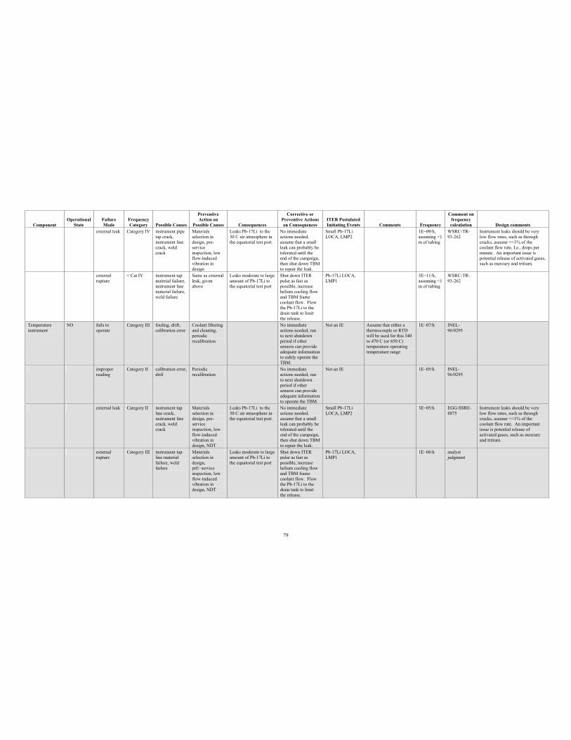
79
Component Operational
StateFailure Mode
Frequency Category Possible Causes
PreventiveAction on
Possible Causes Consequences
Corrective or Preventive Actions on Consequences
ITER Postulated Initiating Events Comments Frequency
Comment on frequency calculation Design comments
external leak Category IV instrument pipe tap crack, instrument line crack, weld crack
Materials selection in design, pre-serviceinspection, low flow-induced vibration in design
Leaks Pb-17Li to the 30 C air atmosphere in the equatorial test port.
No immediate actions needed, assume that a small leak can probably be tolerated until the end of the campaign, then shut down TBM to repair the leak.
Small Pb-17Li LOCA, LMP2
1E 09/h, assuming <1 m of tubing
WSRC-TR-93-262
Instrument leaks should be very low flow rates, such as through cracks, assume <<1% of the coolant flow rate, I.e., drops per minute. An important issue is potential release of activated gases, such as mercury and tritium.
external rupture
< Cat IV instrument tap material failure, instrument line material failure, weld failure
Same as external leak, given above
Leaks moderate to large amount of Pb-17Li to the equatorial test port
Shut down ITER pulse as fast as possible, increase helium cooling flow and TBM frame coolant flow. Flow the Pb-17Li to the drain tank to limit the release.
Pb-17Li LOCA, LMP1
3E 11/h, assuming <1 m of tubing
WSRC-TR-93-262
Temperature instrument
NO fails to operate
Category III fouling, drift, calibration error
Coolant filtering and cleaning, periodic recalibration
No immediate actions needed, run to next shutdown period if other sensors can provide adequate information to safely operate the TBM.
Not an IE Assume that either a thermocouple or RTD will be used for this 340 to 470 C (or 650 C) temperature operating temperature range
1E 07/h INEL-96/0295
improper reading
Category II calibration error, drift
Periodicrecalibration
No immediate actions needed, run to next shutdown period if other sensors can provide adequate information to operate the TBM.
Not an IE 1E 05/h INEL-96/0295
external leak Category II instrument tap line crack, instrument line crack, weld crack
Materials selection in design, pre-serviceinspection, low flow-induced vibration in design, NDT
Leaks Pb-17Li to the 30 C air atmosphere in the equatorial test port.
No immediate actions needed, assume that a small leak can probably be tolerated until the end of the campaign, then shut down TBM to repair the leak.
Small Pb-17Li LOCA, LMP2
3E 05/h EGG-SSRE-8875
Instrument leaks should be very low flow rates, such as through cracks, assume <<1% of the coolant flow rate. An important issue is potential release of activated gases, such as mercury and tritium.
externalrupture
Category III instrument tap line material failure, weld failure
Materials selection in design, prE serviceinspection, low flow-induced vibration in design, NDT
Leaks moderate to large amount of Pb-17Li to the equatorial test port
Shut down ITER pulse as fast as possible, increase helium cooling flow and TBM frame coolant flow. Flow the Pb-17Li to the drain tank to limit the release.
Pb-17Li LOCA, LMP1
1E 06/h analystjudgment
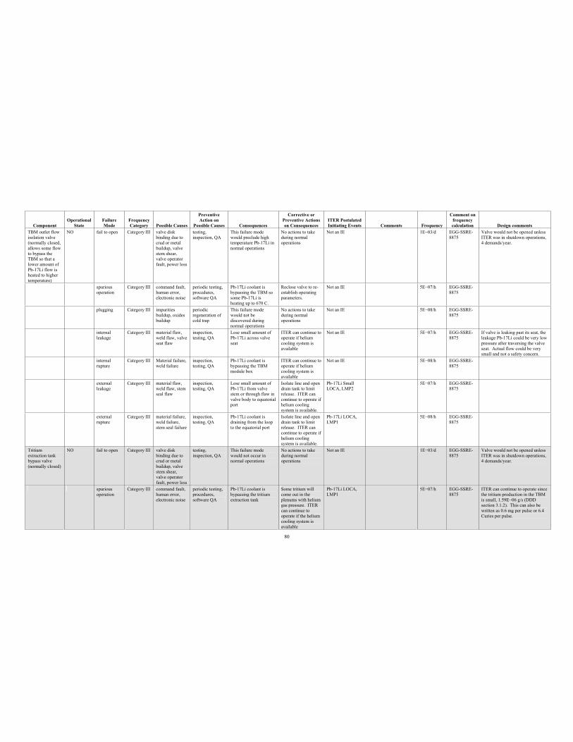
80
Component Operational
StateFailure Mode
Frequency Category Possible Causes
PreventiveAction on
Possible Causes Consequences
Corrective or Preventive Actions on Consequences
ITER Postulated Initiating Events Comments Frequency
Comment on frequency calculation Design comments
TBM outlet flow isolation valve (normally closed, allows some flow to bypass the TBM so that a lower amount of Pb-17Li flow is heated to higher temperature)
NO fail to open Category III valve disk binding due to crud or metal buildup, valve stem shear, valve operator fault, power loss
testing, inspection, QA
This failure mode would preclude high temperature Pb-17Li in normal operations
No actions to take during normal operations
Not an IE 1E 03/d EGG-SSRE-8875
Valve would not be opened unless ITER was in shutdown operations, 4 demands/year.
spurious operation
Category III command fault, human error, electronic noise
periodic testing, procedures, software QA
Pb-17Li coolant is bypassing the TBM so some Pb-17Li is heating up to 670 C.
Reclose valve to re-establish operating parameters.
Not an IE 5E 07/h EGG-SSRE-8875
plugging Category III impurities buildup, oxides buildup
periodic regeneration of cold trap
This failure mode would not be discovered during normal operations
No actions to take during normal operations
Not an IE 5E 08/h EGG-SSRE-8875
internal leakage
Category III material flaw, weld flaw, valve seat flaw
inspection, testing, QA
Lose small amount of Pb-17Li across valve seat
ITER can continue to operate if helium cooling system is available
Not an IE 5E 07/h EGG-SSRE-8875
If valve is leaking past its seat, the leakage Pb-17Li could be very low pressure after traversing the valve seat. Actual flow could be very small and not a safety concern.
internal rupture
Category III Material failure, weld failure
inspection, testing, QA
Pb-17Li coolant is bypassing the TBM module box
ITER can continue to operate if helium cooling system is available
Not an IE 5E 08/h EGG-SSRE-8875
external leakage
Category III material flaw, weld flaw, stem seal flaw
inspection, testing, QA
Lose small amount of Pb-17Li from valve stem or through flaw in valve body to equatorial port
Isolate line and open drain tank to limit release. ITER can continue to operate if helium cooling system is available.
Pb-17Li Small LOCA, LMP2
5E 07/h EGG-SSRE-8875
external rupture
Category III material failure, weld failure, stem seal failure
inspection, testing, QA
Pb-17Li coolant is draining from the loop to the equatorial port
Isolate line and open drain tank to limit release. ITER can continue to operate if helium cooling system is available.
Pb-17Li LOCA, LMP1
5E 08/h EGG-SSRE-8875
Tritium extraction tank bypass valve (normally closed)
NO fail to open Category III valve disk binding due to crud or metal buildup, valve stem shear, valve operator fault, power loss
testing, inspection, QA
This failure mode would not occur in normal operations
No actions to take during normal operations
Not an IE 1E 03/d EGG-SSRE-8875
Valve would not be opened unless ITER was in shutdown operations, 4 demands/year.
spuriousoperation
Category III command fault, human error, electronic noise
periodic testing, procedures, software QA
Pb-17Li coolant is bypassing the tritium extraction tank
Some tritium will come out in the plenums with helium gas pressure. ITER can continue to operate if the helium cooling system is available
Pb-17Li LOCA, LMP1
5E 07/h EGG-SSRE-8875
ITER can continue to operate since the tritium production in the TBM is small, 1.59E 06 g/s (DDD section 3.1.2). This can also be written as 0.6 mg per pulse or 6.4 Curies per pulse.
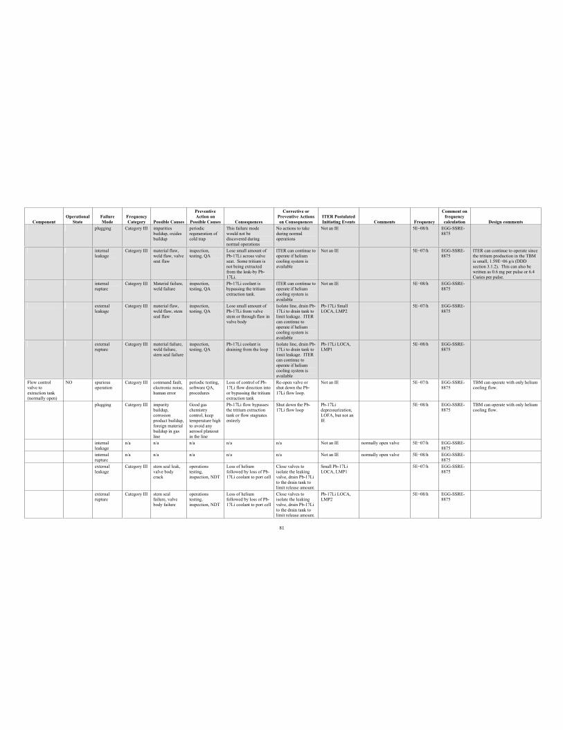
81
Component Operational
StateFailure Mode
Frequency Category Possible Causes
PreventiveAction on
Possible Causes Consequences
Corrective or Preventive Actions on Consequences
ITER Postulated Initiating Events Comments Frequency
Comment on frequency calculation Design comments
plugging Category III impurities buildup, oxides buildup
periodic regeneration of cold trap
This failure mode would not be discovered during normal operations
No actions to take during normal operations
Not an IE 5E 08/h EGG-SSRE-8875
internal leakage
Category III material flaw, weld flaw, valve seat flaw
inspection, testing, QA
Lose small amount of Pb-17Li across valve seat. Some tritium is not being extracted from the leak-by Pb-17Li.
ITER can continue to operate if helium cooling system is available
Not an IE 5E 07/h EGG-SSRE-8875
ITER can continue to operate since the tritium production in the TBM is small, 1.59E 06 g/s (DDD section 3.1.2). This can also be written as 0.6 mg per pulse or 6.4 Curies per pulse.
internal rupture
Category III Material failure, weld failure
inspection, testing, QA
Pb-17Li coolant is bypassing the tritium extraction tank.
ITER can continue to operate if helium cooling system is available
Not an IE 5E 08/h EGG-SSRE-8875
externalleakage
Category III material flaw, weld flaw, stem seal flaw
inspection, testing, QA
Lose small amount of Pb-17Li from valve stem or through flaw in valve body
Isolate line, drain Pb-17Li to drain tank to limit leakage. ITER can continue to operate if helium cooling system is available
Pb-17Li Small LOCA, LMP2
5E 07/h EGG-SSRE-8875
externalrupture
Category III material failure, weld failure, stem seal failure
inspection, testing, QA
Pb-17Li coolant is draining from the loop
Isolate line, drain Pb-17Li to drain tank to limit leakage. ITER can continue to operate if helium cooling system is available
Pb-17Li LOCA, LMP1
5E 08/h EGG-SSRE-8875
Flow control valve to extraction tank (normally open)
NO spurious operation
Category III command fault, electronic noise, human error
periodic testing, software QA, procedures
Loss of control of Pb-17Li flow direction into or bypassing the tritium extraction tank
Re-open valve or shut down the Pb-17Li flow loop.
Not an IE 5E 07/h EGG-SSRE-8875
TBM can operate with only helium cooling flow.
plugging Category III impurity buildup, corrosionproduct buildup, foreign material buildup in gas line
Good gas chemistry control, keep temperature high to avoid any aerosol plateout in the line
Pb-17Li flow bypasses the tritium extraction tank or flow stagnates entirely
Shut down the Pb-17Li flow loop
Pb-17Lidepressurization, LOFA, but not an IE
5E 08/h EGG-SSRE-8875
TBM can operate with only helium cooling flow.
internal leakage
n/a n/a n/a n/a n/a Not an IE normally open valve 5E 07/h EGG-SSRE-8875
internal rupture
n/a n/a n/a n/a n/a Not an IE normally open valve 5E 08/h EGG-SSRE-8875
external leakage
Category III stem seal leak, valve body crack
operations testing, inspection, NDT
Loss of helium followed by loss of Pb-17Li coolant to port cell
Close valves to isolate the leaking valve, drain Pb-17Li to the drain tank to limit release amount.
Small Pb-17Li LOCA, LMP1
5E 07/h EGG-SSRE-8875
external rupture
Category III stem seal failure, valve body failure
operations testing, inspection, NDT
Loss of helium followed by loss of Pb-17Li coolant to port cell
Close valves to isolate the leaking valve, drain Pb-17Li to the drain tank to limit release amount.
Pb-17Li LOCA, LMP2
5E 08/h EGG-SSRE-8875
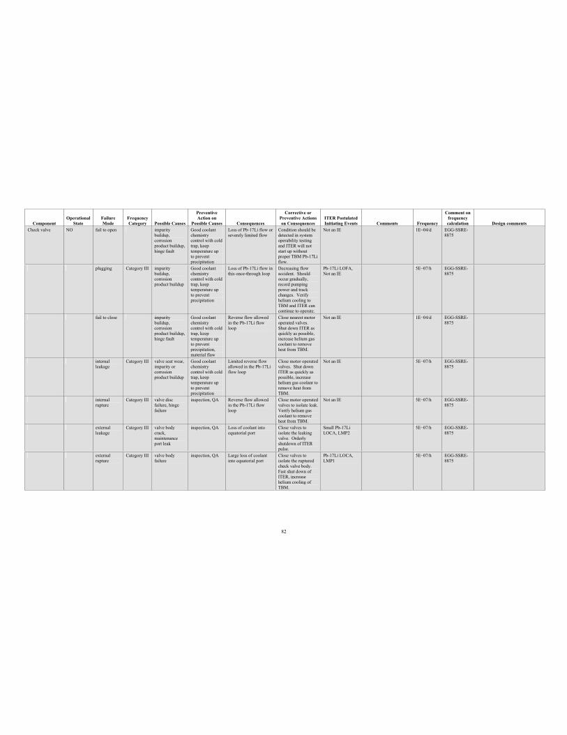
82
Component Operational
StateFailure Mode
Frequency Category Possible Causes
PreventiveAction on
Possible Causes Consequences
Corrective or Preventive Actions on Consequences
ITER Postulated Initiating Events Comments Frequency
Comment on frequency calculation Design comments
Check valve NO fail to open impurity buildup, corrosionproduct buildup, hinge fault
Good coolant chemistry control with cold trap, keep temperature up to prevent precipitation
Loss of Pb-17Li flow or severely limited flow
Condition should be detected in system operability testing and ITER will not start up without proper TBM Pb-17Li flow.
Not an IE 1E 04/d EGG-SSRE-8875
plugging Category III impurity buildup, corrosionproduct buildup
Good coolant chemistry control with cold trap, keep temperature up to prevent precipitation
Loss of Pb-17Li flow in this once-through loop
Decreasing flow accident. Should occur gradually, record pumping power and track changes. Verify helium cooling to TBM and ITER can continue to operate.
Pb-17Li LOFA, Not an IE
5E 07/h EGG-SSRE-8875
fail to close impurity buildup, corrosionproduct buildup, hinge fault
Good coolant chemistry control with cold trap, keep temperature up to prevent precipitation, material flaw
Reverse flow allowed in the Pb-17Li flow loop
Close nearest motor operated valves. Shut down ITER as quickly as possible, increase helium gas coolant to remove heat from TBM.
Not an IE 1E 04/d EGG-SSRE-8875
internal leakage
Category III valve seat wear, impurity or corrosionproduct buildup
Good coolant chemistry control with cold trap, keep temperature up to prevent precipitation
Limited reverse flow allowed in the Pb-17Li flow loop
Close motor operated valves. Shut down ITER as quickly as possible, increase helium gas coolant to remove heat from TBM.
Not an IE 5E 07/h EGG-SSRE-8875
internal rupture
Category III valve disc failure, hinge failure
inspection, QA Reverse flow allowed in the Pb-17Li flow loop
Close motor operated valves to isolate leak. Verify helium gas coolant to remove heat from TBM.
Not an IE 5E 07/h EGG-SSRE-8875
externalleakage
Category III valve body crack,maintenance port leak
inspection, QA Loss of coolant into equatorial port
Close valves to isolate the leaking valve. Orderly shutdown of ITER pulse.
Small Pb-17Li LOCA, LMP2
5E 07/h EGG-SSRE-8875
externalrupture
Category III valve body failure
inspection, QA Large loss of coolant into equatorial port
Close valves to isolate the ruptured check valve body. Fast shut down of ITER, increase helium cooling of TBM.
Pb-17Li LOCA, LMP1
5E 07/h EGG-SSRE-8875
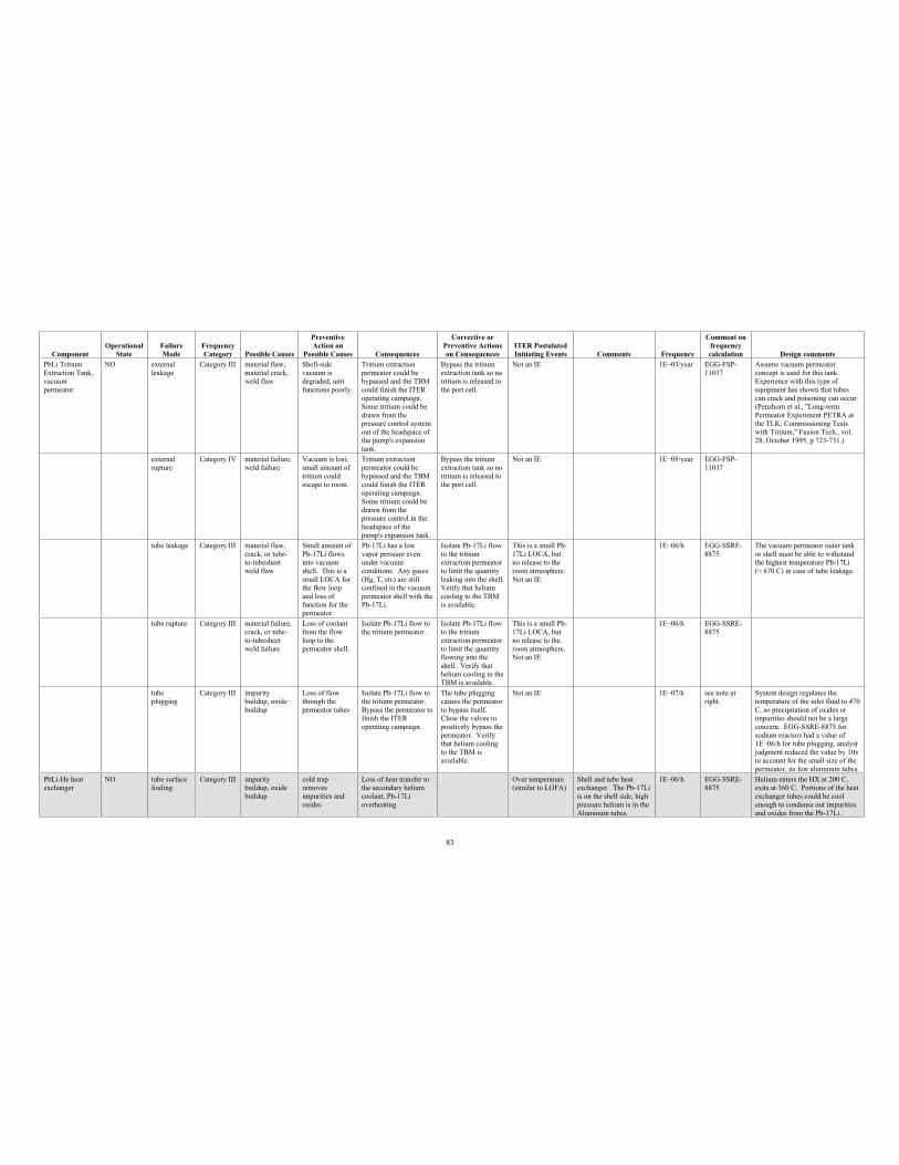
83
Component Operational
StateFailure Mode
Frequency Category Possible Causes
PreventiveAction on
Possible Causes Consequences
Corrective or Preventive Actions on Consequences
ITER Postulated Initiating Events Comments Frequency
Comment on frequency calculation Design comments
PbLi Tritium Extraction Tank, vacuum permeator
NO external leakage
Category III material flaw, material crack, weld flaw
Shell-side vacuum is degraded, unit functions poorly.
Tritium extraction permeator could be bypassed and the TBM could finish the ITER operating campaign. Some tritium could be drawn from the pressure control system out of the headspace of the pump's expansion tank.
Bypass the tritium extraction tank so no tritium is released to the port cell.
Not an IE 1E 03/year EGG-FSP-11037
Assume vacuum permeator concept is used for this tank. Experience with this type of equipment has shown that tubes can crack and poisoning can occur (Penzhorn et al., "Long-term Permeator Experiment PETRA at the TLK: Commissioning Tests with Tritium," Fusion Tech., vol. 28, October 1995, p 723-731.)
external rupture
Category IV material failure, weld failure
Vacuum is lost, small amount of tritium could escape to room.
Tritium extraction permeator could be bypassed and the TBM could finish the ITER operating campaign. Some tritium could be drawn from the pressure control in the headspace of the pump's expansion tank.
Bypass the tritium extraction tank so no tritium is released to the port cell.
Not an IE 1E 05/year EGG-FSP-11037
tube leakage Category III material flaw, crack, or tube-to-tubesheet weld flaw
Small amount of Pb-17Li flows into vacuum shell. This is a small LOCA for the flow loop and loss of function for the permeator.
Pb-17Li has a low vapor pressure even under vacuum conditions. Any gases (Hg, T, etc) are still confined in the vacuum permeator shell with the Pb-17Li.
Isolate Pb-17Li flow to the tritium extraction permeator to limit the quantity leaking into the shell. Verify that helium cooling to the TBM is available.
This is a small Pb-17Li LOCA, but no release to the room atmosphere. Not an IE
1E 06/h EGG-SSRE-8875
The vacuum permeator outer tank or shell must be able to withstand the highest temperature Pb-17Li ( 670 C) in case of tube leakage.
tube rupture Category III material failure, crack, or tube-to-tubesheet weld failure
Loss of coolant from the flow loop to the permeator shell.
Isolate Pb-17Li flow to the tritium permeator.
Isolate Pb-17Li flow to the tritium extraction permeator to limit the quantity flowing into the shell. Verify that helium cooling to the TBM is available.
This is a small Pb-17Li LOCA, but no release to the room atmosphere. Not an IE
1E 06/h EGG-SSRE-8875
tube plugging
Category III impurity buildup, oxide buildup
Loss of flow through the permeator tubes
Isolate Pb-17Li flow to the tritium permeator. Bypass the permeator to finish the ITER operating campaign.
The tube plugging causes the permeator to bypass itself. Close the valves to positively bypass the permeator. Verify that helium cooling to the TBM is available.
Not an IE 1E 07/h see note at right.
System design regulates the temperature of the inlet fluid to 470 C, so precipitation of oxides or impurities should not be a large concern. EGG-SSRE-8875 for sodium reactors had a value of 1E 06/h for tube plugging, analyst judgment reduced the value by 10x to account for the small size of the permeator, its few aluminum tubes.
PbLi-He heat exchanger
NO tube surface fouling
Category III impurity buildup, oxide buildup
cold trap removes impurities and oxides
Loss of heat transfer to the secondary helium coolant, Pb-17Li overheating
Over temperature (similar to LOFA)
Shell and tube heat exchanger. The Pb-17Li is on the shell side, high pressure helium is in the Aluminum tubes.
1E 06/h EGG-SSRE-8875
Helium enters the HX at 200 C, exits at 360 C. Portions of the heat exchanger tubes could be cool enough to condense out impurities and oxides from the Pb-17Li.
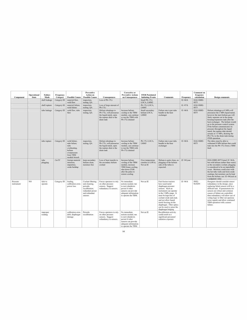
84
Component Operational
StateFailure Mode
Frequency Category Possible Causes
PreventiveAction on
Possible Causes Consequences
Corrective or Preventive Actions on Consequences
ITER Postulated Initiating Events Comments Frequency
Comment on frequency calculation Design comments
shell leakage Category III material flaw, weld flaw
inspection, testing, QA
Loss of Pb-17Li Small Pb-17Li LOCA, LMM2
1E 06/h EGG-SSRE-8875
shell rupture Category III material failure, weld failure
inspection, testing, QA
Loss of large amount of Pb-17Li
Pb-17Li LOCA, LMM1
1E 07/h EGG-SSRE-8875
tube leakage Category III weld flaw, tube flaw
inspection, testing, QA
Helium inleakage to Pb-17Li, will pressurize the liquid metal, open the rupture disk to the drain tank
Increase helium cooling to the TBM module, can continue to run the TBM with Pb-17Li drained
Small secondary helium LOCA, LMM2
Failure rate is per tube bundle in the heat exchanger
1E 06/h EGG-SSRE-8875
Helium inleakage at 8 MPa will pressurize the 2 MPa liquid metal, however the inert helium gas will likely separate out in the pump housing/expansion tank after the heat exchanger. The helium would go to the pressure control system. If the helium communicates its pressure throughout the liquid metal, the rupture disk should actuate at 3.5 MPa, draining the Pb-17Li to the drain tank during ITER operation.
tube rupture Category III weld failure, tube failure, tube overheating, helium overpressure from TBM module breach
inspection, testing, QA
Helium inleakage to Pb-17Li, will pressurize the liquid metal, open the rupture disk to the drain tank
Increase helium cooling to the TBM module, can continue to run the TBM with Pb-17Li drained
Pb-17Li LOCA, LMM1
Failure rate is per tube bundle in the heat exchanger
1E 06/h EGG-SSRE-8875
The tubes must be able to withstand 8 MPa helium that could leak into the Pb-17Li from a TBM fault.
tube plugging
Cat IV foreign material intrusion, impurities, oxide buildup
keep secondary helium clean, moisture free
Loss of heat transfer to the secondary helium coolant
Increase helium cooling of the TBM module, increase TBM frame cooling, shut down ITER after the pulse to restore cooling
Over temperature (similar to LOFA). Not an IE
Helium is quite clean, no plugging of the helium side of the tubes is expected.
1E 04/year EGG-SSRE-8875 listed 1E 06/h, but with helium (rather than water) as the secondary coolant, plugging is considered to be an improbable event. Moisture could react with the hot tube walls and form oxide coatings, but moisture can be kept from the helium, use 1E 04/year as a judgment value
Pressure instrument
NO fails to operate
Category III fouling, calibration error, power loss
Coolant filtering and cleaning, periodic recalibration, redundant power and redundant sensors
Forces operators to rely on other pressure sensors. Suggest redundancy in sensors.
No immediate actions needed, run to next shutdown period if other sensors can provide adequate information to operate the TBM.
Not an IE Fast fission reactors have used metal diaphragm pressure sensors. Such an instrument can operate in the 2 MPa range. It must be kept free of coolant oxide and crud, and not allow liquid metal freezing on the diaphragm. Fiber optics can be used to sense the diaphragm bulging
1E 06/h INEL-96/0295
Designers should consider sensor redundancy in the design, since replacing failed sensors will be a difficult task. If penetrations for sensors are robust and common causes of failure are controlled, then redundancy will allow use of voting logic to filter out spurious noise signals and allow continued TBM operation with a sensor failure.
improper reading
calibration error, drift, diaphragm damage
Periodicrecalibration
Forces operators to rely on other pressure sensors. Suggest redundancy in sensors.
No immediate actions needed, run to next shutdown period if other sensors can provide adequate information to operate the TBM.
Not an IE Recalibration activity could result in a significant personnel radiation exposure
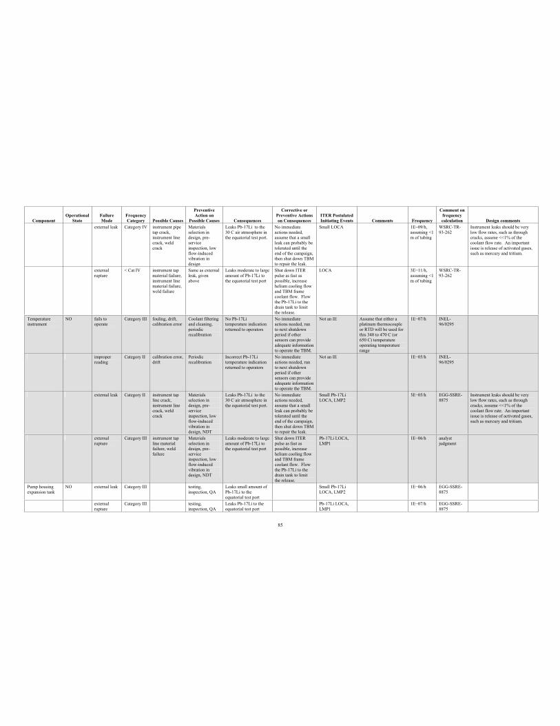
85
Component Operational
StateFailure Mode
Frequency Category Possible Causes
PreventiveAction on
Possible Causes Consequences
Corrective or Preventive Actions on Consequences
ITER Postulated Initiating Events Comments Frequency
Comment on frequency calculation Design comments
external leak Category IV instrument pipe tap crack, instrument line crack, weld crack
Materials selection in design, pre-serviceinspection, low flow-induced vibration in design
Leaks Pb-17Li to the 30 C air atmosphere in the equatorial test port.
No immediate actions needed, assume that a small leak can probably be tolerated until the end of the campaign, then shut down TBM to repair the leak.
Small LOCA 1E 09/h, assuming <1 m of tubing
WSRC-TR-93-262
Instrument leaks should be very low flow rates, such as through cracks, assume <<1% of the coolant flow rate. An important issue is release of activated gases, such as mercury and tritium.
external rupture
< Cat IV instrument tap material failure, instrument line material failure, weld failure
Same as external leak, given above
Leaks moderate to large amount of Pb-17Li to the equatorial test port
Shut down ITER pulse as fast as possible, increase helium cooling flow and TBM frame coolant flow. Flow the Pb-17Li to the drain tank to limit the release.
LOCA 3E 11/h, assuming <1 m of tubing
WSRC-TR-93-262
Temperature instrument
NO fails to operate
Category III fouling, drift, calibration error
Coolant filtering and cleaning, periodic recalibration
No Pb-17Li temperature indication returned to operators
No immediate actions needed, run to next shutdown period if other sensors can provide adequate information to operate the TBM.
Not an IE Assume that either a platinum thermocouple or RTD will be used for this 340 to 470 C (or 650 C) temperature operating temperature range
1E 07/h INEL-96/0295
improper reading
Category II calibration error, drift
Periodicrecalibration
Incorrect Pb-17Li temperature indication returned to operators
No immediate actions needed, run to next shutdown period if other sensors can provide adequate information to operate the TBM.
Not an IE 1E 05/h INEL-96/0295
external leak Category II instrument tap line crack, instrument line crack, weld crack
Materials selection in design, pre-serviceinspection, low flow-induced vibration in design, NDT
Leaks Pb-17Li to the 30 C air atmosphere in the equatorial test port.
No immediate actions needed, assume that a small leak can probably be tolerated until the end of the campaign, then shut down TBM to repair the leak.
Small Pb-17Li LOCA, LMP2
3E 05/h EGG-SSRE-8875
Instrument leaks should be very low flow rates, such as through cracks, assume <<1% of the coolant flow rate. An important issue is release of activated gases, such as mercury and tritium.
externalrupture
Category III instrument tap line material failure, weld failure
Materials selection in design, pre-serviceinspection, low flow-induced vibration in design, NDT
Leaks moderate to large amount of Pb-17Li to the equatorial test port
Shut down ITER pulse as fast as possible, increase helium cooling flow and TBM frame coolant flow. Flow the Pb-17Li to the drain tank to limit the release.
Pb-17Li LOCA, LMP1
1E 06/h analystjudgment
Pump housing expansion tank
NO external leak Category III testing, inspection, QA
Leaks small amount of Pb-17Li to the equatorial test port
Small Pb-17Li LOCA, LMP2
1E 06/h EGG-SSRE-8875
external rupture
Category III testing, inspection, QA
Leaks Pb-17Li to the equatorial test port
Pb-17Li LOCA, LMP1
1E 07/h EGG-SSRE-8875
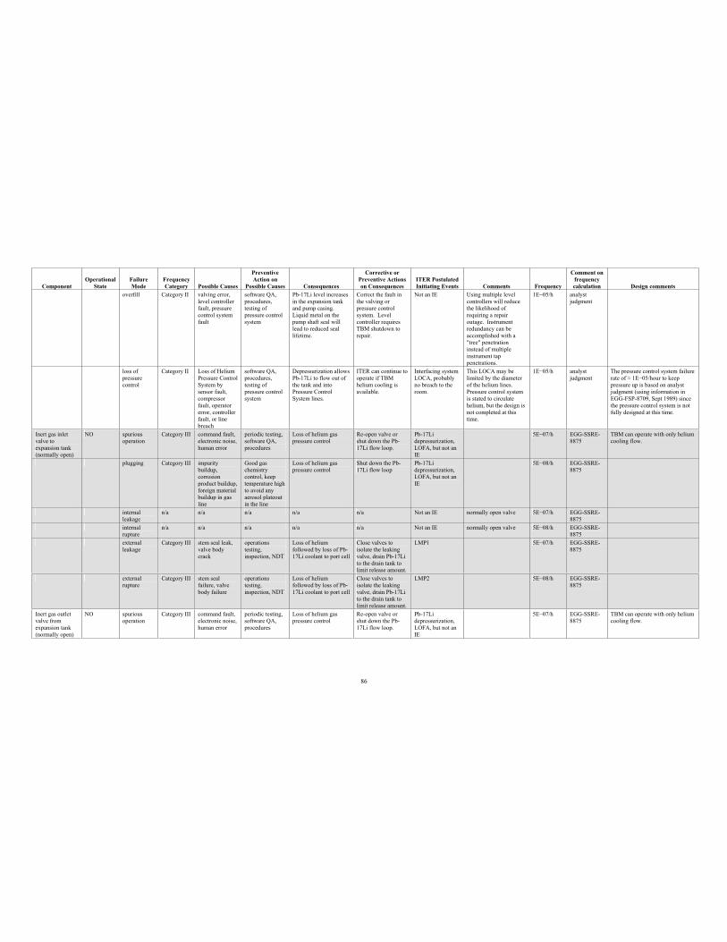
86
Component Operational
StateFailure Mode
Frequency Category Possible Causes
PreventiveAction on
Possible Causes Consequences
Corrective or Preventive Actions on Consequences
ITER Postulated Initiating Events Comments Frequency
Comment on frequency calculation Design comments
overfill Category II valving error, level controller fault, pressure control system fault
software QA, procedures, testing of pressure control system
Pb-17Li level increases in the expansion tank and pump casing. Liquid metal on the pump shaft seal will lead to reduced seal lifetime.
Correct the fault in the valving or pressure control system. Level controller requires TBM shutdown to repair.
Not an IE Using multiple level controllers will reduce the likelihood of requiring a repair outage. Instrument redundancy can be accomplished with a "tree" penetration instead of multiple instrument tap penetrations.
1E 05/h analyst judgment
loss of pressure control
Category II Loss of Helium Pressure Control System by sensor fault, compressor fault, operator error, controller fault, or line breach
software QA, procedures, testing of pressure control system
Depressurization allows Pb-17Li to flow out of the tank and into Pressure Control System lines.
ITER can continue to operate if TBM helium cooling is available.
Interfacing system LOCA, probably no breach to the room.
This LOCA may be limited by the diameter of the helium lines. Pressure control system is stated to circulate helium, but the design is not completed at this time.
1E 05/h analyst judgment
The pressure control system failure rate of 1E 05/hour to keep pressure up is based on analyst judgment (using information in EGG-FSP-8709, Sept 1989) since the pressure control system is not fully designed at this time.
Inert gas inlet valve to expansion tank (normally open)
NO spuriousoperation
Category III command fault, electronic noise, human error
periodic testing, software QA, procedures
Loss of helium gas pressure control
Re-open valve or shut down the Pb-17Li flow loop.
Pb-17Lidepressurization, LOFA, but not an IE
5E 07/h EGG-SSRE-8875
TBM can operate with only helium cooling flow.
plugging Category III impurity buildup, corrosionproduct buildup, foreign material buildup in gas line
Good gas chemistry control, keep temperature high to avoid any aerosol plateout in the line
Loss of helium gas pressure control
Shut down the Pb-17Li flow loop
Pb-17Lidepressurization, LOFA, but not an IE
5E 08/h EGG-SSRE-8875
internal leakage
n/a n/a n/a n/a n/a Not an IE normally open valve 5E 07/h EGG-SSRE-8875
internal rupture
n/a n/a n/a n/a n/a Not an IE normally open valve 5E 08/h EGG-SSRE-8875
externalleakage
Category III stem seal leak, valve body crack
operations testing, inspection, NDT
Loss of helium followed by loss of Pb-17Li coolant to port cell
Close valves to isolate the leaking valve, drain Pb-17Li to the drain tank to limit release amount.
LMP1 5E 07/h EGG-SSRE-8875
externalrupture
Category III stem seal failure, valve body failure
operations testing, inspection, NDT
Loss of helium followed by loss of Pb-17Li coolant to port cell
Close valves to isolate the leaking valve, drain Pb-17Li to the drain tank to limit release amount.
LMP2 5E 08/h EGG-SSRE-8875
Inert gas outlet valve from expansion tank (normally open)
NO spurious operation
Category III command fault, electronic noise, human error
periodic testing, software QA, procedures
Loss of helium gas pressure control
Re-open valve or shut down the Pb-17Li flow loop.
Pb-17Lidepressurization, LOFA, but not an IE
5E 07/h EGG-SSRE-8875
TBM can operate with only helium cooling flow.
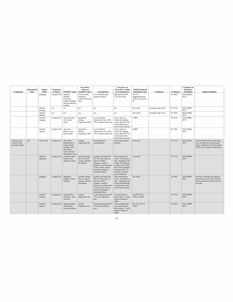
87
Component Operational
StateFailure Mode
Frequency Category Possible Causes
PreventiveAction on
Possible Causes Consequences
Corrective or Preventive Actions on Consequences
ITER Postulated Initiating Events Comments Frequency
Comment on frequency calculation Design comments
plugging Category III impurity buildup, corrosionproduct buildup, foreign material buildup
Good coolant chemistry control with cold trap
Loss of helium gas pressure control
Shut down the Pb-17Li flow loop
Pb-17Lidepressurization, LOFA, but not an IE
5E 08/h EGG-SSRE-8875
internal leakage
n/a n/a n/a n/a n/a Not an IE normally open valve 5E 07/h EGG-SSRE-8875
internal rupture
n/a n/a n/a n/a n/a Not an IE normally open valve 5E 08/h EGG-SSRE-8875
external leakage
Category III stem seal leak, valve body crack
operations testing, inspection, NDT
Loss of helium followed by loss of Pb-17Li coolant to port cell
Close valves to isolate the leaking valve, drain Pb-17Li to the drain tank to limit release amount.
LMP1 5E 07/h EGG-SSRE-8875
external rupture
Category III stem seal failure, valve body failure
operations testing, inspection, NDT
Loss of helium followed by loss of Pb-17Li coolant to port cell
Close valves to isolate the leaking valve, drain Pb-17Li to the drain tank to limit release amount.
LMP2 5E 08/h EGG-SSRE-8875
Cold trap inlet isolation valve (normally open)
NO fail to close Category II valve disk binding due to crud or metal buildup, valve stem shear, valve operator fault, power loss
testing, inspection, QA
No operational consequences
Not an operational concern.
Not an IE 1E 03/d EGG-SSRE-8875
Valve would not be closed unless the cold trap was being cleaned, and it would not be cleaned unless ITER was in shutdown operations
spuriousoperation
Category III command fault, human error, electronic noise
periodic testing, QA on control system, operator procedures
isolates cold trap from Pb-17Li flow loop, so there is no PbLi cleanup. Leads to plateout in coolest parts of the system, such as the heat exchanger, instrument lines.
Slow progression event. No actions to take. Impurities and oxides will build up in other parts of the flow loop. Prudent to shut down Pb-17Li until the cold trap can be repaired.
Not an IE 5E 07/h EGG-SSRE-8875
plugging Category III impurities buildup, oxides buildup
periodic testing, QA on control system, operator procedures
isolates cold trap from Pb-17Li flow loop, so there is no PbLi cleanup. Leads to plateout in coolest parts of the system, such as the heat exchanger, instrument lines.
Slow progression event. No actions to take. Impurities and oxides will build up in other parts of the flow loop over time.
Not an IE 5E 08/h EGG-SSRE-8875
In some cold traps, the impurity plateout occurred at the cold trap throat instead of on the screens in the tank.
externalleakage
Category III material flaw, weld flaw, stem seal flaw
testing, inspection, QA
Leaks high pressure Pb-17Li into equatorial port
Turn off pump to limit release. Verify helium cooling to TBM.
Small Pb-17Li LOCA, LMP2
5E 07/h EGG-SSRE-8875
externalrupture
Category III material failure, weld failure, stem seal failure
testing, inspection, QA
Leaks high pressure Pb-17Li into equatorial port
Turn off pump and open drain tank to limit release. Verify helium cooling to TBM.
Pb-17Li LOCA, LMP1
5E 08/h EGG-SSRE-8875
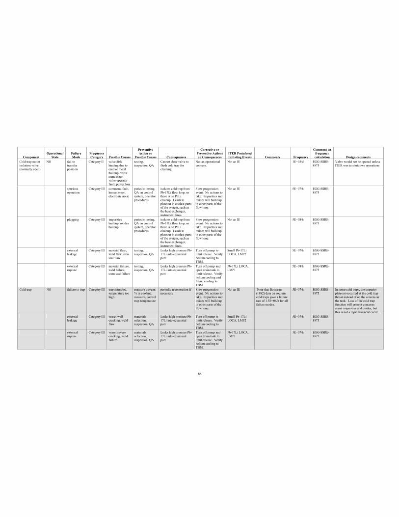
88
Component Operational
StateFailure Mode
Frequency Category Possible Causes
PreventiveAction on
Possible Causes Consequences
Corrective or Preventive Actions on Consequences
ITER Postulated Initiating Events Comments Frequency
Comment on frequency calculation Design comments
Cold trap outlet isolation valve (normally open)
NO fail to transfer position
Category II valve disk binding due to crud or metal buildup, valve stem shear, valve operator fault, power loss
testing, inspection, QA
Cannot close valve to flush cold trap for cleaning.
Not an operational concern.
Not an IE 1E 03/d EGG-SSRE-8875
Valve would not be opened unless ITER was in shutdown operations
spurious operation
Category III command fault, human error, electronic noise
periodic testing, QA on control system, operator procedures
isolates cold trap from Pb-17Li flow loop, so there is no PbLi cleanup. Leads to plateout in coolest parts of the system, such as the heat exchanger, instrument lines.
Slow progression event. No actions to take. Impurities and oxides will build up in other parts of the flow loop.
Not an IE 5E 07/h EGG-SSRE-8875
plugging Category III impurities buildup, oxides buildup
periodic testing, QA on control system, operator procedures
isolates cold trap from Pb-17Li flow loop, so there is no PbLi cleanup. Leads to plateout in coolest parts of the system, such as the heat exchanger, instrument lines.
Slow progression event. No actions to take. Impurities and oxides will build up in other parts of the flow loop.
Not an IE 5E 08/h EGG-SSRE-8875
external leakage
Category III material flaw, weld flaw, stem seal flaw
testing, inspection, QA
Leaks high pressure Pb-17Li into equatorial port
Turn off pump to limit release. Verify helium cooling to TBM.
Small Pb-17Li LOCA, LMP2
5E 07/h EGG-SSRE-8875
external rupture
Category III material failure, weld failure, stem seal failure
testing, inspection, QA
Leaks high pressure Pb-17Li into equatorial port
Turn off pump and open drain tank to limit release. Verify helium cooling and frame cooling to TBM.
Pb-17Li LOCA, LMP1
5E 08/h EGG-SSRE-8875
Cold trap NO failure to trap Category III trap saturated, temperature too high
measure oxygen % in coolant; measure, control trap temperature
periodic regeneration if necessary
Slow progression event. No actions to take. Impurities and oxides will build up in other parts of the flow loop.
Not an IE Note that Boisseau (1982) data on sodium cold traps gave a failure rate of 1.5E 06/h for all failure modes.
5E 07/h EGG-SSRE-8875
In some cold traps, the impurity plateout occurred at the cold trap throat instead of on the screens in the tank. Loss of the cold trap function will present concerns about impurities and oxides, but this is not a rapid transient event.
externalleakage
Category III vessel wall cracking, weld flaw
materials selection, inspection, QA
Leaks high pressure Pb-17Li into equatorial port
Turn off pump to limit release. Verify helium cooling to TBM.
Small Pb-17Li LOCA, LMP2
5E 07/h EGG-SSRE-8875
externalrupture
Category III vessel severe cracking, weld failure
materials selection, inspection, QA
Leaks high pressure Pb-17Li into equatorial port
Turn off pump and open drain tank to limit release. Verify helium cooling to TBM.
Pb-17Li LOCA, LMP1
5E 07/h EGG-SSRE-8875
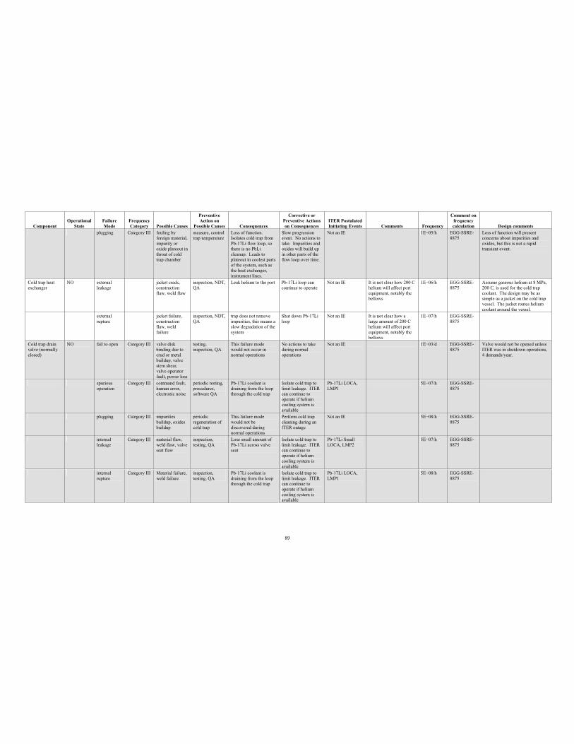
89
Component Operational
StateFailure Mode
Frequency Category Possible Causes
PreventiveAction on
Possible Causes Consequences
Corrective or Preventive Actions on Consequences
ITER Postulated Initiating Events Comments Frequency
Comment on frequency calculation Design comments
plugging Category III fouling by foreign material, impurity or oxide plateout in throat of cold trap chamber
measure, control trap temperature
Loss of function. Isolates cold trap from Pb-17Li flow loop, so there is no PbLi cleanup. Leads to plateout in coolest parts of the system, such as the heat exchanger, instrument lines.
Slow progression event. No actions to take. Impurities and oxides will build up in other parts of the flow loop over time.
Not an IE 1E 05/h EGG-SSRE-8875
Loss of function will present concerns about impurities and oxides, but this is not a rapid transient event.
Cold trap heat exchanger
NO external leakage
jacket crack, construction flaw, weld flaw
inspection, NDT, QA
Leak helium to the port Pb-17Li loop can continue to operate
Not an IE It is not clear how 200 C helium will affect port equipment, notably the bellows
1E 06/h EGG-SSRE-8875
Assume gaseous helium at 8 MPa, 200 C, is used for the cold trap coolant. The design may be as simple as a jacket on the cold trap vessel. The jacket routes helium coolant around the vessel.
external rupture
jacket failure, construction flaw, weld failure
inspection, NDT, QA
trap does not remove impurities, this means a slow degradation of the system
Shut down Pb-17Li loop
Not an IE It is not clear how a large amount of 200 C helium will affect port equipment, notably the bellows
1E 07/h EGG-SSRE-8875
Cold trap drain valve (normally closed)
NO fail to open Category III valve disk binding due to crud or metal buildup, valve stem shear, valve operator fault, power loss
testing, inspection, QA
This failure mode would not occur in normal operations
No actions to take during normal operations
Not an IE 1E 03/d EGG-SSRE-8875
Valve would not be opened unless ITER was in shutdown operations, 4 demands/year.
spuriousoperation
Category III command fault, human error, electronic noise
periodic testing, procedures, software QA
Pb-17Li coolant is draining from the loop through the cold trap
Isolate cold trap to limit leakage. ITER can continue to operate if helium cooling system is available
Pb-17Li LOCA, LMP1
5E 07/h EGG-SSRE-8875
plugging Category III impurities buildup, oxides buildup
periodic regeneration of cold trap
This failure mode would not be discovered during normal operations
Perform cold trap cleaning during an ITER outage
Not an IE 5E 08/h EGG-SSRE-8875
internal leakage
Category III material flaw, weld flaw, valve seat flaw
inspection, testing, QA
Lose small amount of Pb-17Li across valve seat
Isolate cold trap to limit leakage. ITER can continue to operate if helium cooling system is available
Pb-17Li Small LOCA, LMP2
5E 07/h EGG-SSRE-8875
internal rupture
Category III Material failure, weld failure
inspection, testing, QA
Pb-17Li coolant is draining from the loop through the cold trap
Isolate cold trap to limit leakage. ITER can continue to operate if helium cooling system is available
Pb-17Li LOCA, LMP1
5E 08/h EGG-SSRE-8875
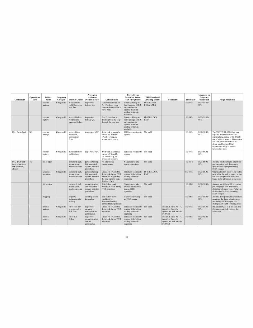
90
Component Operational
StateFailure Mode
Frequency Category Possible Causes
PreventiveAction on
Possible Causes Consequences
Corrective or Preventive Actions on Consequences
ITER Postulated Initiating Events Comments Frequency
Comment on frequency calculation Design comments
externalleakage
Category III material flaw, weld flaw, stem seal flaw
inspection, testing, QA
Lose small amount of Pb-17Li from valve stem or through flaw in valve body
Isolate cold trap to limit leakage. ITER can continue to operate if helium cooling system is available
Pb-17Li Small LOCA, LMP2
5E 07/h EGG-SSRE-8875
externalrupture
Category III material failure, weld failure, stem seal failure
inspection, testing, QA
Pb-17Li coolant is draining from the loop through the cold trap
Isolate cold trap to limit leakage. ITER can continue to operate if helium cooling system is available
Pb-17Li LOCA, LMP1
5E 08/h EGG-SSRE-8875
PbLi Drain Tank NO external leakage
Category III material flaw, weld flaw, construction fault
inspection, NDT drain tank is normally valved off from Pb-17Li flow loop, no immediate concern
ITER can continue to operate
Not an IE 1E 06/h EGG-SSRE-8875
The TRITEX Pb-17Li flow loop kept the drain tank above the melting temperature of Pb-17Li by use of electric heaters. There was a concern for thermal shock if a dump quickly placed high temperature alloy in a room temperature tank.
external rupture
Category III material failure, weld failure
inspection, NDT drain tank is normally valved off from Pb-17Li flow loop, no immediate concern
ITER can continue to operate
Not an IE 1E 07/h EGG-SSRE-8875
PbLi drain tank inlet valve from HX (normally closed)
NO fail to open command fault, human error, electronic noise
periodic testing, QA on control system, operator procedures
No operational consequences
No actions to take during operations
Not an IE 1E 03/d EGG-SSRE-8875
Assume one fill or refill operation per campaign, so 4 demands to open the valve per year during ITER outages
spuriousoperation
Category III command fault, human error, electronic noise
periodic testing, QA on control system, operator procedures
Drains Pb-17Li to the drain tank during ITER operation. Regarding the heat transfer loop, this is a LOCA.
ITER can continue to operate if the helium cooling system is operating
Pb-17Li LOCA, LMP1
5E 07/h EGG-SSRE-8875
Opening the low point valve on the tank while the tank is merely under 0.1 MPa gas pressure will allow liquid metal admission to the tank.
fail to close command fault, human error, electronic noise
periodic testing, QA on control system, operator procedures
This failure mode would not occur during ITER operation.
No actions to take for this failure mode during ITER operation
Not an IE 1E 03/d EGG-SSRE-8875
Assume one fill or refill operation per campaign, so 4 demands to close the valve per year. Failure to close would only occur during ITER outages.
plugging impurity buildup, oxide buildup
cold trap cleans the coolant
This failure mode would not be discovered during normal ITER operation.
Clean valve during an ITER outage
Not an IE 5E 08/h EGG-SSRE-8875
Assume that operational evolutions requiring the drain valve to open are during ITER outages, not during ITER TBM operating time.
internal leakage
Category III valve seat flaw or wear, valve disk flaw
inspection, periodic testing,QA on construction
Drains Pb-17Li to the drain tank during ITER operation.
ITER can continue to operate if the helium cooling system is operating
Not an IE Not an IE since Pb-17Li is not lost from the system, no leak into the Port Cell
5E 07/h EGG-SSRE-8875
Helium inert gas is in the tank and this gas would leak out past the valve seat.
internal rupture
Category III valve disk failure
inspection, periodic testing, QA on construction
Drains Pb-17Li to the drain tank during ITER operation.
ITER can continue to operate if the helium cooling system is operating
Not an IE Not an IE since Pb-17Li is not lost from the system, no leak into the Port Cell
5E 08/h EGG-SSRE-8875
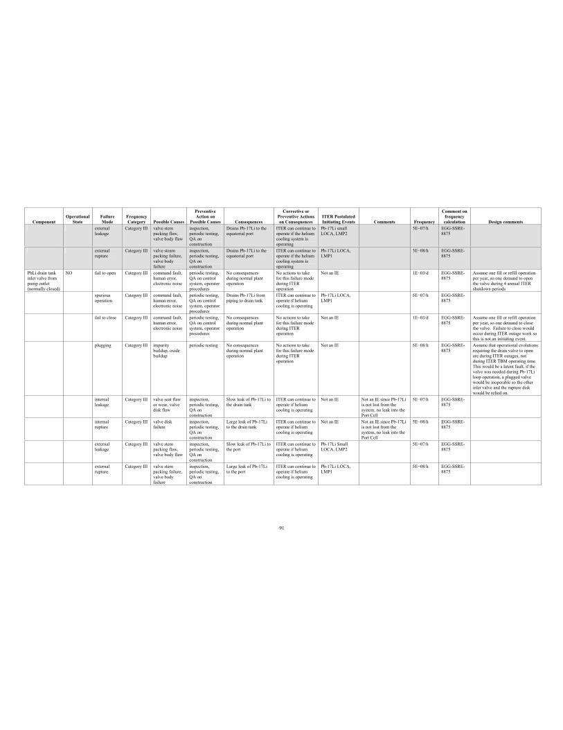
91
Component Operational
StateFailure Mode
Frequency Category Possible Causes
PreventiveAction on
Possible Causes Consequences
Corrective or Preventive Actions on Consequences
ITER Postulated Initiating Events Comments Frequency
Comment on frequency calculation Design comments
externalleakage
Category III valve stem packing flaw, valve body flaw
inspection, periodic testing, QA on construction
Drains Pb-17Li to the equatorial port
ITER can continue to operate if the helium cooling system is operating
Pb-17Li small LOCA, LMP2
5E 07/h EGG-SSRE-8875
externalrupture
Category III valve steam packing failure, valve body failure
inspection, periodic testing, QA on construction
Drains Pb-17Li to the equatorial port
ITER can continue to operate if the helium cooling system is operating
Pb-17Li LOCA, LMP1
5E 08/h EGG-SSRE-8875
PbLi drain tank inlet valve from pump outlet (normally closed)
NO fail to open Category III command fault, human error, electronic noise
periodic testing, QA on control system, operator procedures
No consequences during normal plant operation
No actions to take for this failure mode during ITER operation
Not an IE 1E 03/d EGG-SSRE-8875
Assume one fill or refill operation per year, so one demand to open the valve during 4 annual ITER shutdown periods
spurious operation
Category III command fault, human error, electronic noise
periodic testing, QA on control system, operator procedures
Drains Pb-17Li from piping to drain tank
ITER can continue to operate if helium cooling is operating
Pb-17Li LOCA, LMP1
5E 07/h EGG-SSRE-8875
fail to close Category III command fault, human error, electronic noise
periodic testing, QA on control system, operator procedures
No consequences during normal plant operation
No actions to take for this failure mode during ITER operation
Not an IE 1E 03/d EGG-SSRE-8875
Assume one fill or refill operation per year, so one demand to close the valve. Failure to close would occur during ITER outage work so this is not an initiating event.
plugging Category III impurity buildup, oxide buildup
periodic testing No consequences during normal plant operation
No actions to take for this failure mode during ITER operation
Not an IE 5E 08/h EGG-SSRE-8875
Assume that operational evolutions requiring the drain valve to open are during ITER outages, not during ITER TBM operating time. This would be a latent fault, if the valve was needed during Pb-17Li loop operation, a plugged valve would be inoperable so the other inlet valve and the rupture disk would be relied on.
internal leakage
Category III valve seat flaw or wear, valve disk flaw
inspection, periodic testing, QA on construction
Slow leak of Pb-17Li to the drain tank
ITER can continue to operate if helium cooling is operating
Not an IE Not an IE since Pb-17Li is not lost from the system, no leak into the Port Cell
5E 07/h EGG-SSRE-8875
internal rupture
Category III valve disk failure
inspection, periodic testing, QA on construction
Large leak of Pb-17Li to the drain tank
ITER can continue to operate if helium cooling is operating
Not an IE Not an IE since Pb-17Li is not lost from the system, no leak into the Port Cell
5E 08/h EGG-SSRE-8875
external leakage
Category III valve stem packing flaw, valve body flaw
inspection, periodic testing, QA on construction
Slow leak of Pb-17Li to the port
ITER can continue to operate if helium cooling is operating
Pb-17Li Small LOCA, LMP2
5E 07/h EGG-SSRE-8875
external rupture
Category III valve stem packing failure, valve body failure
inspection, periodic testing, QA on construction
Large leak of Pb-17Li to the port
ITER can continue to operate if helium cooling is operating
Pb-17Li LOCA, LMP1
5E 08/h EGG-SSRE-8875
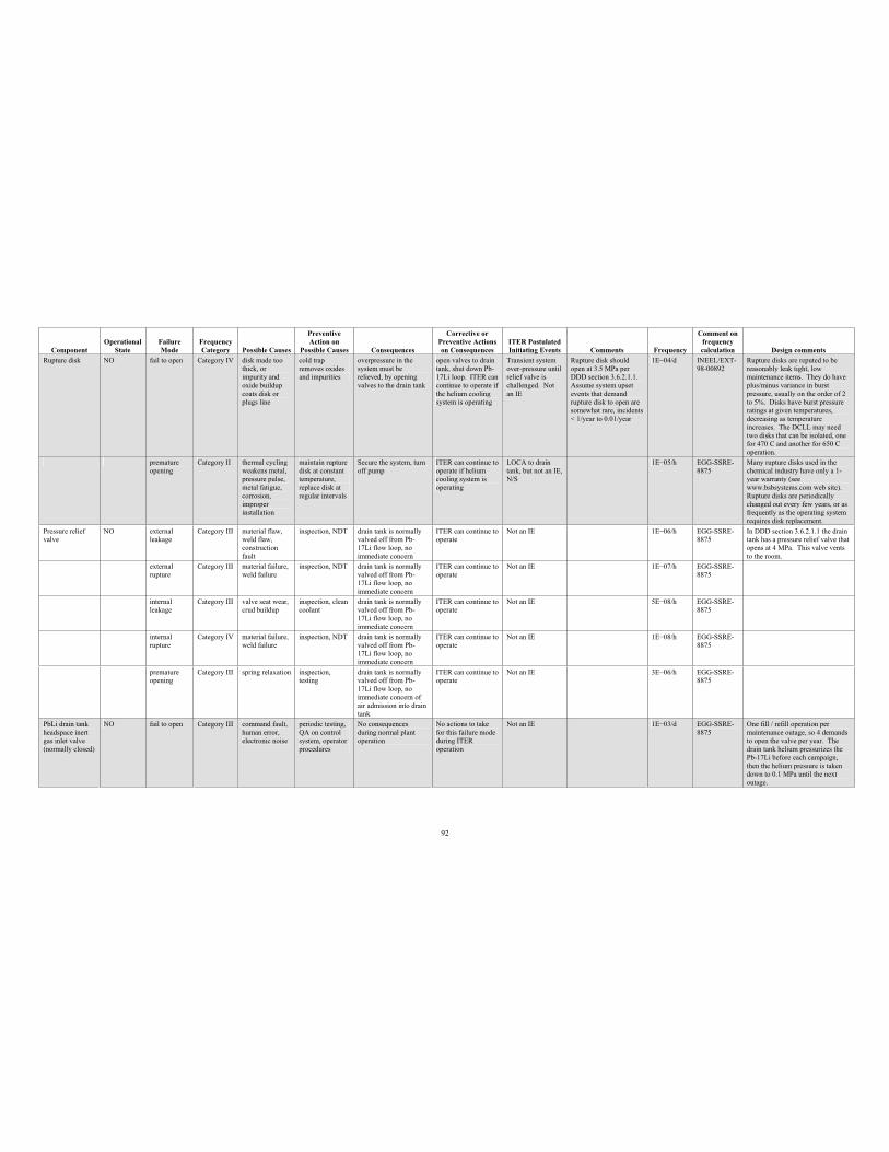
92
Component Operational
StateFailure Mode
Frequency Category Possible Causes
PreventiveAction on
Possible Causes Consequences
Corrective or Preventive Actions on Consequences
ITER Postulated Initiating Events Comments Frequency
Comment on frequency calculation Design comments
Rupture disk NO fail to open Category IV disk made too thick, or impurity and oxide buildup coats disk or plugs line
cold trap removes oxides and impurities
overpressure in the system must be relieved, by opening valves to the drain tank
open valves to drain tank, shut down Pb-17Li loop. ITER can continue to operate if the helium cooling system is operating
Transient system over-pressure until relief valve is challenged. Not an IE
Rupture disk should open at 3.5 MPa per DDD section 3.6.2.1.1. Assume system upset events that demand rupture disk to open are somewhat rare, incidents < 1/year to 0.01/year
1E 04/d INEEL/EXT-98-00892
Rupture disks are reputed to be reasonably leak tight, low maintenance items. They do have plus/minus variance in burst pressure, usually on the order of 2 to 5%. Disks have burst pressure ratings at given temperatures, decreasing as temperature increases. The DCLL may need two disks that can be isolated, one for 470 C and another for 650 C operation.
premature opening
Category II thermal cycling weakens metal, pressure pulse, metal fatigue, corrosion,improper installation
maintain rupture disk at constant temperature, replace disk at regular intervals
Secure the system, turn off pump
ITER can continue to operate if helium cooling system is operating
LOCA to drain tank, but not an IE, N/S
1E 05/h EGG-SSRE-8875
Many rupture disks used in the chemical industry have only a 1-year warranty (see www.bsbsystems.com web site). Rupture disks are periodically changed out every few years, or as frequently as the operating system requires disk replacement.
Pressure relief valve
NO external leakage
Category III material flaw, weld flaw, construction fault
inspection, NDT drain tank is normally valved off from Pb-17Li flow loop, no immediate concern
ITER can continue to operate
Not an IE 1E 06/h EGG-SSRE-8875
In DDD section 3.6.2.1.1 the drain tank has a pressure relief valve that opens at 4 MPa. This valve vents to the room.
external rupture
Category III material failure, weld failure
inspection, NDT drain tank is normally valved off from Pb-17Li flow loop, no immediate concern
ITER can continue to operate
Not an IE 1E 07/h EGG-SSRE-8875
internal leakage
Category III valve seat wear, crud buildup
inspection, clean coolant
drain tank is normally valved off from Pb-17Li flow loop, no immediate concern
ITER can continue to operate
Not an IE 5E 08/h EGG-SSRE-8875
internal rupture
Category IV material failure, weld failure
inspection, NDT drain tank is normally valved off from Pb-17Li flow loop, no immediate concern
ITER can continue to operate
Not an IE 1E 08/h EGG-SSRE-8875
premature opening
Category III spring relaxation inspection, testing
drain tank is normally valved off from Pb-17Li flow loop, no immediate concern of air admission into drain tank
ITER can continue to operate
Not an IE 3E 06/h EGG-SSRE-8875
PbLi drain tank headspace inert gas inlet valve (normally closed)
NO fail to open Category III command fault, human error, electronic noise
periodic testing, QA on control system, operator procedures
No consequences during normal plant operation
No actions to take for this failure mode during ITER operation
Not an IE 1E 03/d EGG-SSRE-8875
One fill / refill operation per maintenance outage, so 4 demands to open the valve per year. The drain tank helium pressurizes the Pb-17Li before each campaign, then the helium pressure is taken down to 0.1 MPa until the next outage.
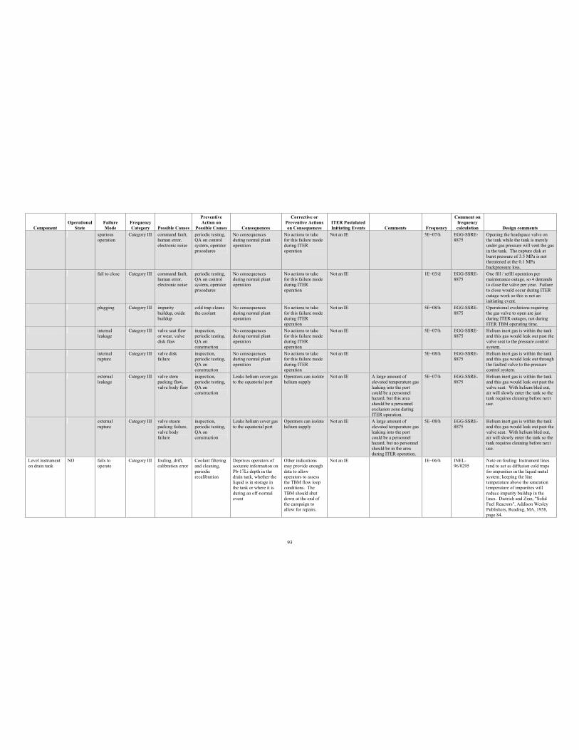
93
Component Operational
StateFailure Mode
Frequency Category Possible Causes
PreventiveAction on
Possible Causes Consequences
Corrective or Preventive Actions on Consequences
ITER Postulated Initiating Events Comments Frequency
Comment on frequency calculation Design comments
spuriousoperation
Category III command fault, human error, electronic noise
periodic testing, QA on control system, operator procedures
No consequences during normal plant operation
No actions to take for this failure mode during ITER operation
Not an IE 5E 07/h EGG-SSRE-8875
Opening the headspace valve on the tank while the tank is merely under gas pressure will vent the gas in the tank. The rupture disk at burst pressure of 3.5 MPa is not threatened at the 0.1 MPa backpressure loss.
fail to close Category III command fault, human error, electronic noise
periodic testing, QA on control system, operator procedures
No consequences during normal plant operation
No actions to take for this failure mode during ITER operation
Not an IE 1E 03/d EGG-SSRE-8875
One fill / refill operation per maintenance outage, so 4 demands to close the valve per year. Failure to close would occur during ITER outage work so this is not an initiating event.
plugging Category III impurity buildup, oxide buildup
cold trap cleans the coolant
No consequences during normal plant operation
No actions to take for this failure mode during ITER operation
Not an IE 5E 08/h EGG-SSRE-8875
Operational evolutions requiring the gas valve to open are just during ITER outages, not during ITER TBM operating time.
internal leakage
Category III valve seat flaw or wear, valve disk flaw
inspection, periodic testing, QA on construction
No consequences during normal plant operation
No actions to take for this failure mode during ITER operation
Not an IE 5E 07/h EGG-SSRE-8875
Helium inert gas is within the tank and this gas would leak out past the valve seat to the pressure control system.
internal rupture
Category III valve disk failure
inspection, periodic testing, QA on construction
No consequences during normal plant operation
No actions to take for this failure mode during ITER operation
Not an IE 5E 08/h EGG-SSRE-8875
Helium inert gas is within the tank and this gas would leak out through the faulted valve to the pressure control system.
externalleakage
Category III valve stem packing flaw, valve body flaw
inspection, periodic testing, QA on construction
Leaks helium cover gas to the equatorial port
Operators can isolate helium supply
Not an IE A large amount of elevated temperature gas leaking into the port could be a personnel hazard, but this area should be a personnel exclusion zone during ITER operation.
5E 07/h EGG-SSRE-8875
Helium inert gas is within the tank and this gas would leak out past the valve seat. With helium bled out, air will slowly enter the tank so the tank requires cleaning before next use.
externalrupture
Category III valve steam packing failure, valve body failure
inspection, periodic testing, QA on construction
Leaks helium cover gas to the equatorial port
Operators can isolate helium supply
Not an IE A large amount of elevated temperature gas leaking into the port could be a personnel hazard, but no personnel should be in the area during ITER operation.
5E 08/h EGG-SSRE-8875
Helium inert gas is within the tank and this gas would leak out past the valve seat. With helium bled out, air will slowly enter the tank so the tank requires cleaning before next use.
Level instrument on drain tank
NO fails to operate
Category III fouling, drift, calibration error
Coolant filtering and cleaning, periodic recalibration
Deprives operators of accurate information on Pb-17Li depth in the drain tank, whether the liquid is in storage in the tank or where it is during an off-normal event
Other indications may provide enough data to allow operators to assess the TBM flow loop conditions. The TBM should shut down at the end of the campaign to allow for repairs.
Not an IE 1E 06/h INEL-96/0295
Note on fouling: Instrument lines tend to act as diffusion cold traps for impurities in the liquid metal system; keeping the line temperature above the saturation temperature of impurities will reduce impurity buildup in the lines. Dietrich and Zinn, "Solid Fuel Reactors", Addison Wesley Publishers, Reading, MA, 1958, page 84.
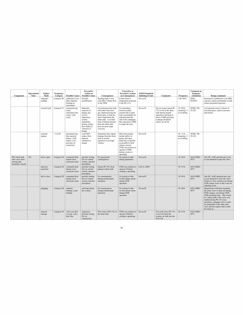
94
Component Operational
StateFailure Mode
Frequency Category Possible Causes
PreventiveAction on
Possible Causes Consequences
Corrective or Preventive Actions on Consequences
ITER Postulated Initiating Events Comments Frequency
Comment on frequency calculation Design comments
improper reading
Category III calibration error, drift, impurity buildup on instrument
Periodicrecalibration
Reading high or low will affect volume flow in the TBM
Could result in temperature transient in the Pb-17Li.
Not an IE 1.4E 06/h INEL-96/0295
Instrument recalibration is an ORE concern, remote instruments would reduce personnel exposure.
external leak Category IV instrument tap crack,instrument line crack, weld crack
Materials selection in design, pre-serviceinspection, system operability testing, reduce flow-induced vibration in design
An instrument line leak will either leak inert gas, depressurizing the drain tank, or leak the 'heel' liquid from the drain tank. A coolant leak of limited amount from the drain tank does not pose large concerns.
No immediate actions needed, assume that a small leak can probably be tolerated until the end of the campaign, then shut down TBM to repair the leak.
Not an IE Do not expect much Pb-17Li to be in the drain tank during normal operation, and kept at below 8 MPa pressure. Leakage should be minor, not an IE.
1E 09/h, assuming <1 m of tubing
WSRC-TR-93-262
An important issue is release of activated gases, such as mercury and tritium.
external rupture
< Cat IV instrument tap line material failure, weld failure, over-pressure on instrument
weld NDT, reduce flow-inducedvibration in design
Instrument line rupture leakage from the drain tank in normal operation is not high volume.
Shut down pump, isolate inflow to pump, and open drain line as quickly as possible to limit release amount. ITER can continue to operate if TBM helium system is operating.
Not an IE 3E 11/h, assuming <1 m of tubing
WSRC-TR-93-262
PbLi drain tank inlet valve from mixing tank (normally closed)
NO fail to open Category III command fault, human error, electronic noise
periodic testing, QA on control system, operator procedures
No operational consequences
No actions to take during operations
Not an IE 1E 03/d EGG-SSRE-8875
One fill / refill operation per year, so one demand to open the valve
spuriousoperation
Category III command fault, human error, electronic noise
periodic testing, QA on control system, operator procedures
Drains Pb-17Li from piping to drain tank
ITER can continue to operate if helium cooling is operating
LOCA, LMP1 5E 07/h EGG-SSRE-8875
fail to close Category III command fault, human error, electronic noise
periodic testing, QA on control system, operator procedures
No consequences during normal plant operation
No actions to take for this failure mode during ITER operation
Not an IE 1E 03/d EGG-SSRE-8875
One fill / refill operation per year, so one demand to close the valve. Failure to close would occur during ITER outage work so this is not an initiating event.
plugging Category III impurity buildup, oxide buildup
cold trap cleans the coolant
No consequences during normal plant operation
No actions to take for this failure mode during ITER operation
Not an IE 5E 08/h EGG-SSRE-8875
Operational evolutions requiring the drain valve to open are during ITER outages, not during ITER TBM operating time. This would be a latent fault, if the valve was needed during Pb-17Li loop operation, a plugged valve would be inoperable so the other inlet valve and the rupture disk would be relied on.
internal leakage
Category III valve seat flaw or wear, valve disk flaw
inspection, periodic testing, QA on construction
Slow leak of Pb-17Li to the drain tank
ITER can continue to operate if helium cooling is operating
Not an IE Not an IE since Pb-17Li is not lost from the system, no leak into the Port Cell
5E 07/h EGG-SSRE-8875
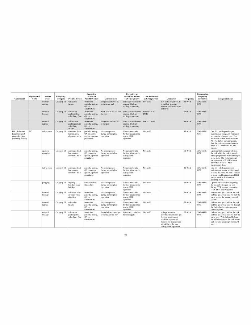
95
Component Operational
StateFailure Mode
Frequency Category Possible Causes
PreventiveAction on
Possible Causes Consequences
Corrective or Preventive Actions on Consequences
ITER Postulated Initiating Events Comments Frequency
Comment on frequency calculation Design comments
internal rupture
Category III valve disk failure
inspection, periodic testing, QA on construction
Large leak of Pb-17Li to the drain tank
ITER can continue to operate if helium cooling is operating
Not an IE Not an IE since Pb-17Li is not lost from the system, no leak into the Port Cell
5E 08/h EGG-SSRE-8875
externalleakage
Category III valve stem packing flaw, valve body flaw
inspection, periodic testing, QA on construction
Slow leak of Pb-17Li to the port
ITER can continue to operate if helium cooling is operating
Small LOCA, LMP2
5E 07/h EGG-SSRE-8875
externalrupture
Category III valve steam packing failure, valve body failure
inspection, periodic testing, QA on construction
Large leak of Pb-17Li to the port
ITER can continue to operate if helium cooling is operating
LOCA, LMP1 5E 08/h EGG-SSRE-8875
PbLi drain tank headspace inert gas outlet valve (normally closed)
NO fail to open Category III command fault, human error, electronic noise
periodic testing, QA on control system, operator procedures
No consequences during normal plant operation
No actions to take for this failure mode during ITER operation
Not an IE 1E 03/d EGG-SSRE-8875
One fill / refill operation per maintenance outage, so 4 demands to open the valve per year. The drain tank helium pressurizes the Pb-17Li before each campaign, then the helium pressure is taken down to 0.1 MPa until the next outage.
spurious operation
Category III command fault, human error, electronic noise
periodic testing, QA on control system, operator procedures
No consequences during normal plant operation
No actions to take for this failure mode during ITER operation
Not an IE 5E 07/h EGG-SSRE-8875
Opening the headspace valve on the tank while the tank is merely under gas pressure will vent the gas in the tank. The rupture disk at burst pressure of 3.5 MPa is not threatened at the 0.1 MPa backpressure loss.
fail to close Category III command fault, human error, electronic noise
periodic testing, QA on control system, operator procedures
No consequences during normal plant operation
No actions to take for this failure mode during ITER operation
Not an IE 1E 03/d EGG-SSRE-8875
One fill / refill operation per maintenance outage, so 4 demands to close the valve per year. Failure to close would occur during ITER outage work so this is not an initiating event.
plugging Category III impurity buildup, oxide buildup
cold trap cleans the coolant
No consequences during normal plant operation
No actions to take for this failure mode during ITER operation
Not an IE 5E 08/h EGG-SSRE-8875
Operational evolutions requiring the gas valve to open are just during ITER outages, not during ITER TBM operating time.
internal leakage
Category III valve seat flaw or wear, valve disk flaw
inspection, periodic testing, QA on construction
No consequences during normal plant operation
No actions to take for this failure mode during ITER operation
Not an IE 5E 07/h EGG-SSRE-8875
Helium inert gas is within the tank and this gas would leak out past the valve seat to the pressure control system.
internal rupture
Category III valve disk failure
inspection, periodic testing, QA on construction
No consequences during normal plant operation
No actions to take for this failure mode during ITER operation
Not an IE 5E 08/h EGG-SSRE-8875
Helium inert gas is within the tank and this gas would leak out through the faulted valve to the pressure control system.
external leakage
Category III valve stem packing flaw, valve body flaw
inspection, periodic testing, QA on construction
Leaks helium cover gas to the equatorial port
Operators can isolate helium supply
Not an IE A large amount of elevated temperature gas leaking into the port could be a personnel hazard, but no personnel should be in the area during ITER operation.
5E 07/h EGG-SSRE-8875
Helium inert gas is within the tank and this gas would leak out past the valve seat. With helium bled out, air will slowly enter the tank so the tank requires cleaning before next use.
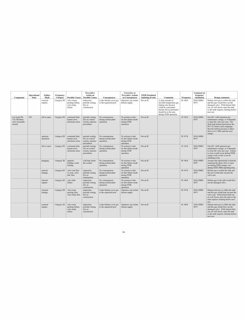
96
Component Operational
StateFailure Mode
Frequency Category Possible Causes
PreventiveAction on
Possible Causes Consequences
Corrective or Preventive Actions on Consequences
ITER Postulated Initiating Events Comments Frequency
Comment on frequency calculation Design comments
external rupture
Category III valve steam packing failure, valve body failure
inspection, periodic testing, QA on construction
Leaks helium cover gas to the equatorial port
Operators can isolate helium supply
Not an IE A large amount of elevated temperature gas leaking into the port could be a personnel hazard, but no personnel should be in the area during ITER operation.
5E 08/h EGG-SSRE-8875
Helium inert gas is within the tank and this gas would flow out the damaged valve. With helium bled out, air will slowly enter the tank so the tank requires cleaning before next use.
Low point Pb-17Li fill/drain valve (normally closed)
NO fail to open Category III command fault, human error, electronic noise
periodic testing, QA on control system, operator procedures
No consequences during normal plant operation
No actions to take for this failure mode during ITER operation
Not an IE 1E 03/d EGG-SSRE-8875
One fill / refill operation per maintenance outage, so 4 demands to open the valve per year. The drain tank helium pressurizes the Pb-17Li before each campaign, then the helium pressure is taken down to 0.1 MPa until the next outage.
spuriousoperation
Category III command fault, human error, electronic noise
periodic testing, QA on control system, operator procedures
No consequences during normal plant operation
No actions to take for this failure mode during ITER operation
Not an IE 5E 07/h EGG-SSRE-8875
fail to close Category III command fault, human error, electronic noise
periodic testing, QA on control system, operator procedures
No consequences during normal plant operation
No actions to take for this failure mode during ITER operation
Not an IE 1E 03/d EGG-SSRE-8875
One fill / refill operation per maintenance outage, so 4 demands to close the valve per year. Failure to close would occur during ITER outage work so this is not an initiating event.
plugging Category III impurity buildup, oxide buildup
cold trap cleans the coolant
No consequences during normal plant operation
No actions to take for this failure mode during ITER operation
Not an IE 5E 08/h EGG-SSRE-8875
Assume that operational evolutions requiring the drain valve to open are during ITER outages, not during ITER TBM operating time.
internal leakage
Category III valve seat flaw or wear, valve disk flaw
inspection, periodic testing, QA on construction
No consequences during normal plant operation
No actions to take for this failure mode during ITER operation
Not an IE 5E 07/h EGG-SSRE-8875
Helium gas is within the tank and this gas would leak out past the valve seat.
internal rupture
Category III valve disk failure
inspection, periodic testing, QA on construction
No consequences during normal plant operation
No actions to take for this failure mode during ITER operation
Not an IE 5E 08/h EGG-SSRE-8875
Helium gas in the tank would flow out the damaged valve
externalleakage
Category III valve stem packing flaw, valve body flaw
inspection, periodic testing, QA on construction
Leaks helium cover gas to the equatorial port
Operators can isolate helium supply
Not an IE 5E 07/h EGG-SSRE-8875
Helium inert gas is within the tank and this gas would leak out past the valve seat. With helium bled out, air will slowly enter the tank so the tank requires cleaning before next use.
externalrupture
Category III valve stem packing failure, valve body failure
inspection, periodic testing, QA on construction
Leaks helium cover gas to the equatorial port
Operators can isolate helium supply
Not an IE 5E 08/h EGG-SSRE-8875
Helium inert gas is within the tank and this gas would flow out the damaged valve. With helium bled out, air will slowly enter the tank so the tank requires cleaning before next use.
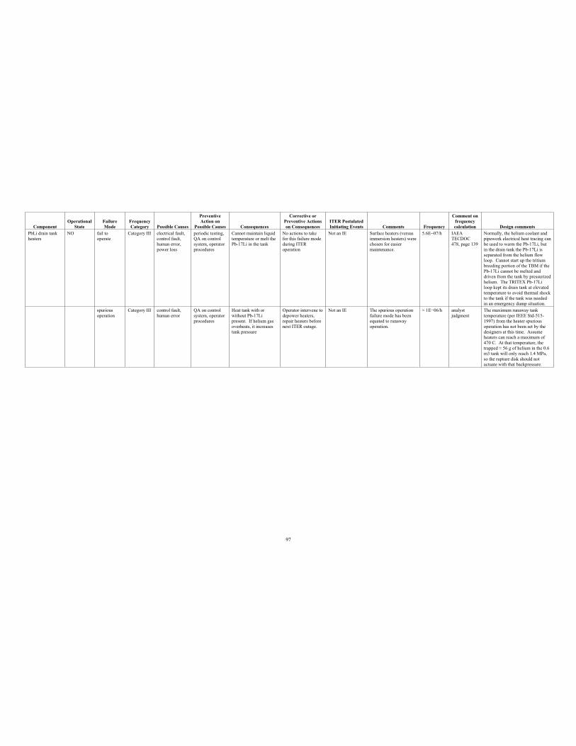
97
Component Operational
StateFailure Mode
Frequency Category Possible Causes
PreventiveAction on
Possible Causes Consequences
Corrective or Preventive Actions on Consequences
ITER Postulated Initiating Events Comments Frequency
Comment on frequency calculation Design comments
PbLi drain tank heaters
NO fail to operate
Category III electrical fault, control fault, human error, power loss
periodic testing, QA on control system, operator procedures
Cannot maintain liquid temperature or melt the Pb-17Li in the tank
No actions to take for this failure mode during ITER operation
Not an IE Surface heaters (versus immersion heaters) were chosen for easier maintenance.
5.6E 07/h IAEA TECDOC478, page 139
Normally, the helium coolant and pipework electrical heat tracing can be used to warm the Pb-17Li, but in the drain tank the Pb-17Li is separated from the helium flow loop. Cannot start up the tritium breeding portion of the TBM if the Pb-17Li cannot be melted and driven from the tank by pressurized helium. The TRITEX Pb-17Li loop kept its drain tank at elevated temperature to avoid thermal shock to the tank if the tank was needed in an emergency dump situation.
spurious operation
Category III control fault, human error
QA on control system, operator procedures
Heat tank with or without Pb-17Li present. If helium gas overheats, it increases tank pressure
Operator intervene to depower heaters, repair heaters before next ITER outage.
Not an IE The spurious operation failure mode has been equated to runaway operation.
1E 06/h analyst judgment
The maximum runaway tank temperature (per IEEE Std-515-1997) from the heater spurious operation has not been set by the designers at this time. Assume heaters can reach a maximum of 470 C. At that temperature, the trapped 56 g of helium in the 0.6 m3 tank will only reach 1.4 MPa, so the rupture disk should not actuate with that backpressure.
98
Appendix B
Preliminary Failure Modes and Effects Analysis for the Helium Flow Loop
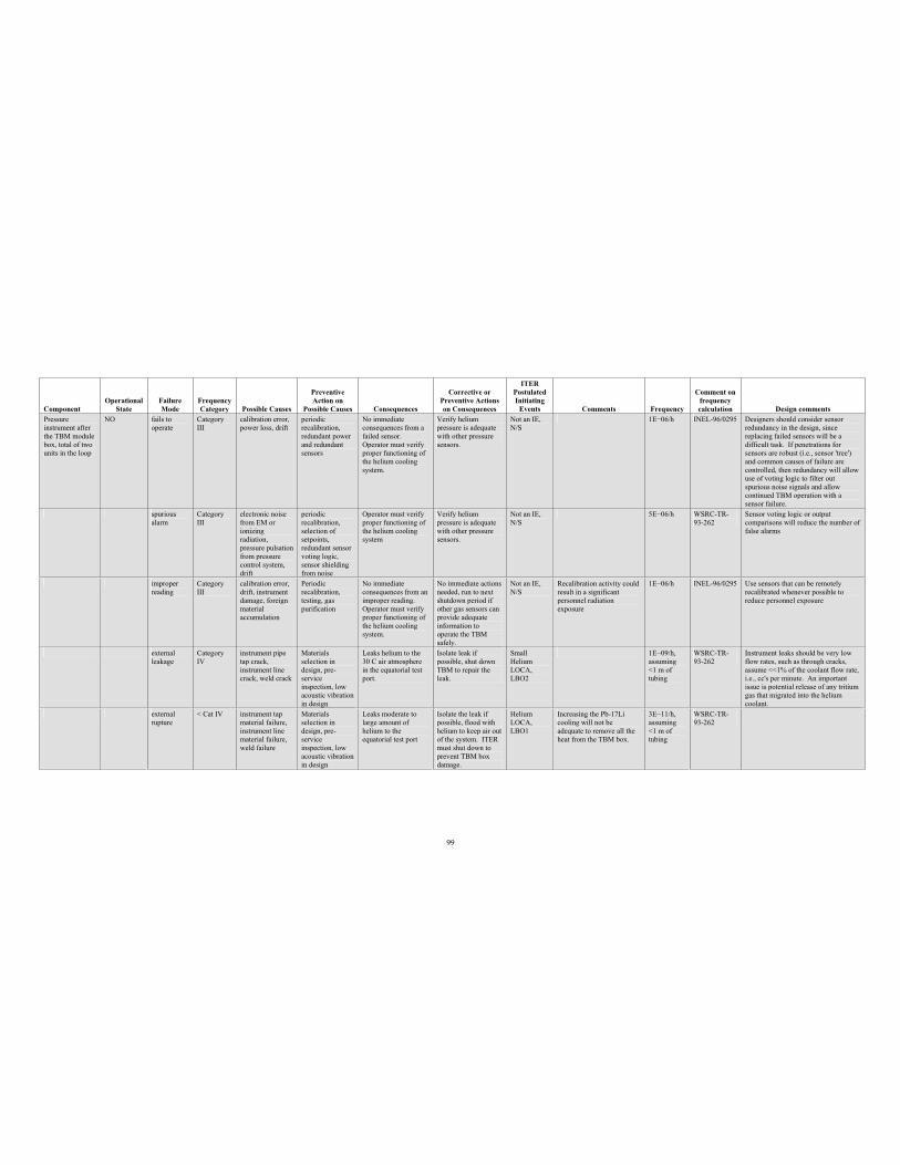
99
Component Operational
StateFailure Mode
Frequency Category Possible Causes
PreventiveAction on
Possible Causes Consequences
Corrective or Preventive Actions on Consequences
ITERPostulated Initiating
Events Comments Frequency
Comment on frequency calculation Design comments
Pressure instrument after the TBM module box, total of two units in the loop
NO fails to operate
Category III
calibration error, power loss, drift
periodic recalibration, redundant power and redundant sensors
No immediate consequences from a failed sensor. Operator must verify proper functioning of the helium cooling system.
Verify helium pressure is adequate with other pressure sensors.
Not an IE, N/S
1E 06/h INEL-96/0295 Designers should consider sensor redundancy in the design, since replacing failed sensors will be a difficult task. If penetrations for sensors are robust (i.e., sensor 'tree') and common causes of failure are controlled, then redundancy will allow use of voting logic to filter out spurious noise signals and allow continued TBM operation with a sensor failure.
spuriousalarm
Category III
electronic noise from EM or ionizing radiation, pressure pulsation from pressure control system, drift
periodic recalibration, selection of setpoints, redundant sensor voting logic, sensor shielding from noise
Operator must verify proper functioning of the helium cooling system
Verify helium pressure is adequate with other pressure sensors.
Not an IE, N/S
5E 06/h WSRC-TR-93-262
Sensor voting logic or output comparisons will reduce the number of false alarms
improper reading
Category III
calibration error, drift, instrument damage, foreign material accumulation
Periodicrecalibration, testing, gas purification
No immediate consequences from an improper reading. Operator must verify proper functioning of the helium cooling system.
No immediate actions needed, run to next shutdown period if other gas sensors can provide adequate information to operate the TBM safely.
Not an IE, N/S
Recalibration activity could result in a significant personnel radiation exposure
1E 06/h INEL-96/0295 Use sensors that can be remotely recalibrated whenever possible to reduce personnel exposure
externalleakage
Category IV
instrument pipe tap crack, instrument line crack, weld crack
Materials selection in design, pre-serviceinspection, low acoustic vibration in design
Leaks helium to the 30 C air atmosphere in the equatorial test port.
Isolate leak if possible, shut down TBM to repair the leak.
Small Helium LOCA,LBO2
1E 09/h, assuming <1 m of tubing
WSRC-TR-93-262
Instrument leaks should be very low flow rates, such as through cracks, assume <<1% of the coolant flow rate, i.e., cc's per minute. An important issue is potential release of any tritium gas that migrated into the helium coolant.
externalrupture
< Cat IV instrument tap material failure, instrument line material failure, weld failure
Materials selection in design, pre-serviceinspection, low acoustic vibration in design
Leaks moderate to large amount of helium to the equatorial test port
Isolate the leak if possible, flood with helium to keep air out of the system. ITER must shut down to prevent TBM box damage.
Helium LOCA,LBO1
Increasing the Pb-17Li cooling will not be adequate to remove all the heat from the TBM box.
3E 11/h, assuming <1 m of tubing
WSRC-TR-93-262
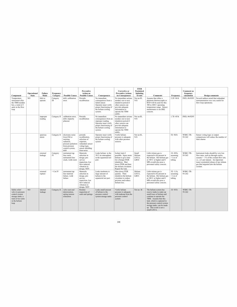
100
Component Operational
StateFailure Mode
Frequency Category Possible Causes
PreventiveAction on
Possible Causes Consequences
Corrective or Preventive Actions on Consequences
ITERPostulated Initiating
Events Comments Frequency
Comment on frequency calculation Design comments
Temperature instrument after the TBM module box, a total of 3 units in the flow loop
NO fails to operate
Category III
drift, calibration error
Periodicrecalibration
No immediate consequences from a failed sensor. Operator must verify proper functioning of the helium cooling system.
No immediate actions needed, run to next shutdown period if other sensors can provide adequate information to operate the TBM safely.
Not an IE, N/S
Assume that either a platinum thermocouple or RTD will be used for this 380 to 440 C operating temperature range. Sensor maintenance is an ORE concern.
2.2E 06/h INEL-96/0295 Several authors noted that redundant instrumentation was very useful for flow loop operations.
improper reading
Category II calibration error, drift, impurity plateout
Periodicrecalibration
No immediate consequences from an improper reading. Operator must verify proper functioning of the helium cooling system.
No immediate actions needed, run to next shutdown period if other sensors can provide adequate information to operate the TBM safely.
Not an IE, N/S
1.7E 05/h INEL-96/0295
spurious alarm
Category II electronic noise from EM or ionizing radiation, pressure pulsation from pressure control system, drift
periodic recalibration, selection of setpoints, redundant sensor voting logic, sensor shielding from noise
Operator must verify proper functioning of the helium cooling system
Verify helium pressure is adequate with other pressure sensors.
Not an IE, N/S
5E 06/h WSRC-TR-93-262
Sensor voting logic or output comparisons will reduce the number of false alarms
external leakage
Category IV
instrument tap line crack, instrument line crack, weld crack
Materials selection in design, pre-serviceinspection, low flow-induced vibration in design, NDT
Leaks helium to the 30 C air atmosphere in the equatorial test port.
Isolate leak if possible. Inject more helium to give time for a benign ITER shutdown. Shut down ITER and then the helium circulator. Repair the leak.
Small Helium LOCA,LBO2
Little tritium gas is expected to be present in the helium. Hot helium gas at 340 C or higher and 8 MPa would also pose a personnel safety concern.
1E 09/h, assuming <1 m of tubing
WSRC-TR-93-262
Instrument leaks should be very low flow rates, such as through cracks, assume 1% of the coolant flow rate, i.e., cc's per minute. An important issue is potential release of any tritium gas that migrated into the helium coolant.
external rupture
< Cat IV instrument tap line material failure, weld failure
Materials selection in design, pre-serviceinspection, low flow-induced vibration in design, NDT
Leaks moderate to large amount of helium to the equatorial test port
Shut down ITER quickly. Then shutdown the helium circulator to reduce pressure and reduce helium loss.
Helium LOCA,LBO1
Little tritium gas is expected to be present in the helium. Hot helium gas at 340 C or higher and 8 MPa would also pose a personnel safety concern.
3E 11/h, assuming <1 m of tubing
WSRC-TR-93-262
Safety relief valve to pressure control system storage tanks, a total of two units in the helium loop
NO internal leakage
Category II valve seat seal deterioration, spring tension relaxation
Routine inspection of seals and springs
Leaks small amount of helium to the pressure control system storage tanks
Verify helium pressure is adequate with makeup from the pressure control system
Not an IE The helium system has reserve tanks to make up small loses of helium and continue to operate the TBM. Assume that this leak, which is captured in the pressure control system storage tanks, can be made up. This event is not a small LOCA.
1E 05/h WSRC-TR-93-262
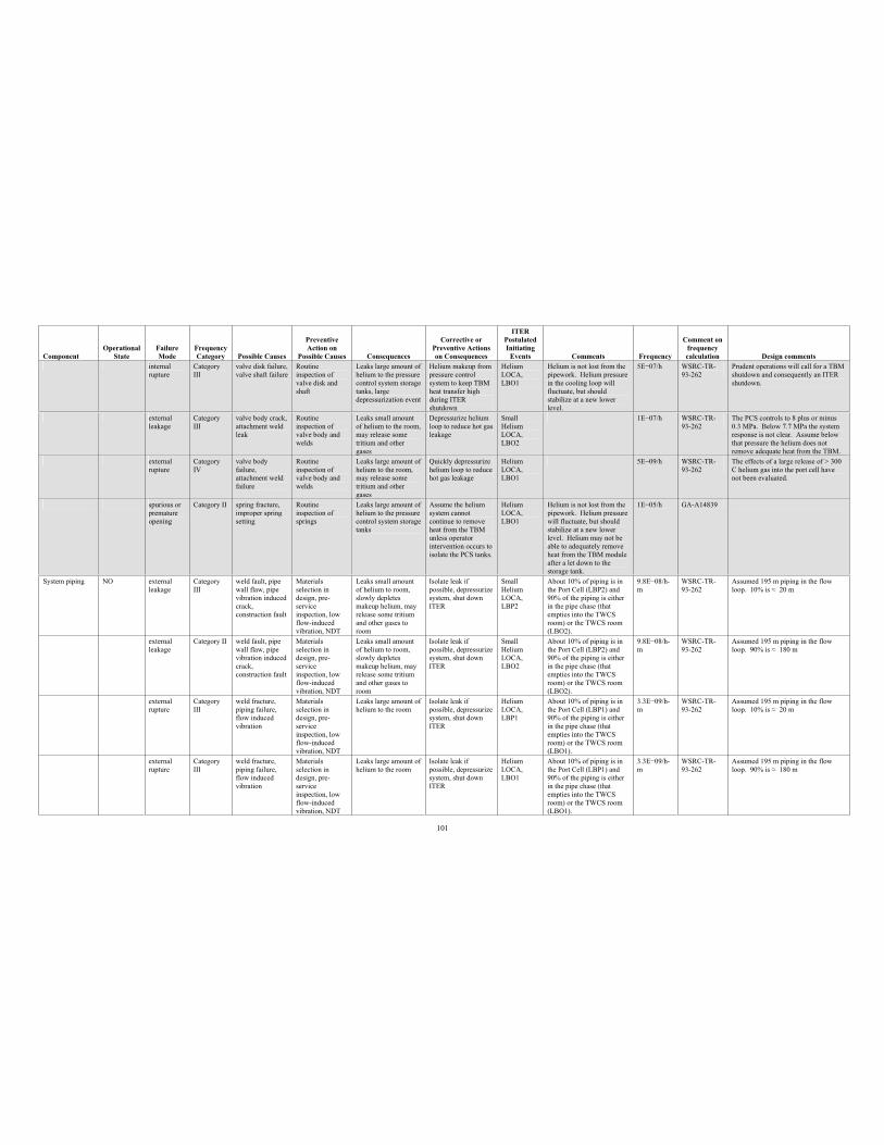
101
Component Operational
StateFailure Mode
Frequency Category Possible Causes
PreventiveAction on
Possible Causes Consequences
Corrective or Preventive Actions on Consequences
ITERPostulated Initiating
Events Comments Frequency
Comment on frequency calculation Design comments
internal rupture
Category III
valve disk failure, valve shaft failure
Routine inspection of valve disk and shaft
Leaks large amount of helium to the pressure control system storage tanks, large depressurization event
Helium makeup from pressure control system to keep TBM heat transfer high during ITER shutdown
Helium LOCA,LBO1
Helium is not lost from the pipework. Helium pressure in the cooling loop will fluctuate, but should stabilize at a new lower level.
5E 07/h WSRC-TR-93-262
Prudent operations will call for a TBM shutdown and consequently an ITER shutdown.
externalleakage
Category III
valve body crack, attachment weld leak
Routine inspection of valve body and welds
Leaks small amount of helium to the room, may release some tritium and other gases
Depressurize helium loop to reduce hot gas leakage
Small Helium LOCA,LBO2
1E 07/h WSRC-TR-93-262
The PCS controls to 8 plus or minus 0.3 MPa. Below 7.7 MPa the system response is not clear. Assume below that pressure the helium does not remove adequate heat from the TBM.
externalrupture
Category IV
valve body failure, attachment weld failure
Routine inspection of valve body and welds
Leaks large amount of helium to the room, may release some tritium and other gases
Quickly depressurize helium loop to reduce hot gas leakage
Helium LOCA,LBO1
5E 09/h WSRC-TR-93-262
The effects of a large release of > 300 C helium gas into the port cell have not been evaluated.
spurious or premature opening
Category II spring fracture, improper spring setting
Routine inspection of springs
Leaks large amount of helium to the pressure control system storage tanks
Assume the helium system cannot continue to remove heat from the TBM unless operator intervention occurs to isolate the PCS tanks.
Helium LOCA,LBO1
Helium is not lost from the pipework. Helium pressure will fluctuate, but should stabilize at a new lower level. Helium may not be able to adequately remove heat from the TBM module after a let down to the storage tank.
1E 05/h GA-A14839
System piping NO external leakage
Category III
weld fault, pipe wall flaw, pipe vibration induced crack,construction fault
Materials selection in design, pre-serviceinspection, low flow-induced vibration, NDT
Leaks small amount of helium to room, slowly depletes makeup helium, may release some tritium and other gases to room
Isolate leak if possible, depressurize system, shut down ITER
Small Helium LOCA,LBP2
About 10% of piping is in the Port Cell (LBP2) and 90% of the piping is either in the pipe chase (that empties into the TWCS room) or the TWCS room (LBO2).
9.8E 08/h-m
WSRC-TR-93-262
Assumed 195 m piping in the flow loop. 10% is 20 m
external leakage
Category II weld fault, pipe wall flaw, pipe vibration induced crack,construction fault
Materials selection in design, pre-serviceinspection, low flow-induced vibration, NDT
Leaks small amount of helium to room, slowly depletes makeup helium, may release some tritium and other gases to room
Isolate leak if possible, depressurize system, shut down ITER
Small Helium LOCA,LBO2
About 10% of piping is in the Port Cell (LBP2) and 90% of the piping is either in the pipe chase (that empties into the TWCS room) or the TWCS room (LBO2).
9.8E 08/h-m
WSRC-TR-93-262
Assumed 195 m piping in the flow loop. 90% is 180 m
external rupture
Category III
weld fracture, piping failure, flow induced vibration
Materials selection in design, pre-serviceinspection, low flow-induced vibration, NDT
Leaks large amount of helium to the room
Isolate leak if possible, depressurize system, shut down ITER
Helium LOCA,LBP1
About 10% of piping is in the Port Cell (LBP1) and 90% of the piping is either in the pipe chase (that empties into the TWCS room) or the TWCS room (LBO1).
3.3E 09/h-m
WSRC-TR-93-262
Assumed 195 m piping in the flow loop. 10% is 20 m
external rupture
Category III
weld fracture, piping failure, flow induced vibration
Materials selection in design, pre-serviceinspection, low flow-induced vibration, NDT
Leaks large amount of helium to the room
Isolate leak if possible, depressurize system, shut down ITER
Helium LOCA,LBO1
About 10% of piping is in the Port Cell (LBP1) and 90% of the piping is either in the pipe chase (that empties into the TWCS room) or the TWCS room (LBO1).
3.3E 09/h-m
WSRC-TR-93-262
Assumed 195 m piping in the flow loop. 90% is 180 m
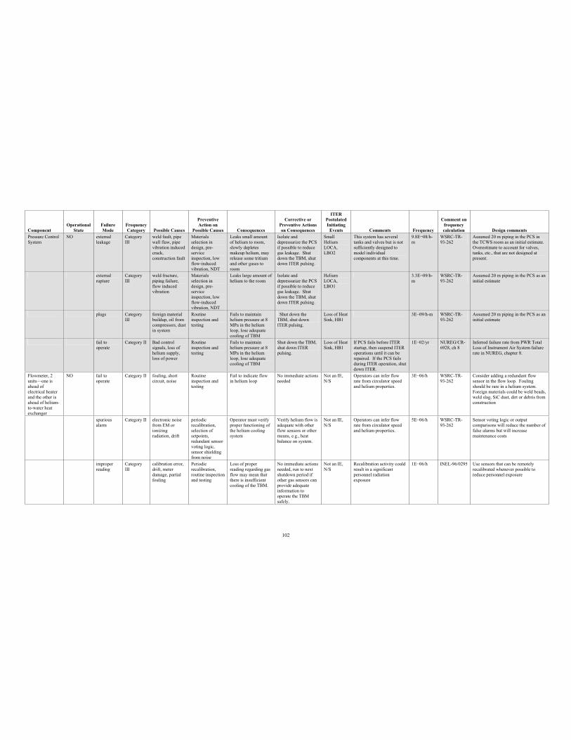
102
Component Operational
StateFailure Mode
Frequency Category Possible Causes
PreventiveAction on
Possible Causes Consequences
Corrective or Preventive Actions on Consequences
ITERPostulated Initiating
Events Comments Frequency
Comment on frequency calculation Design comments
Pressure Control System
NO externalleakage
Category III
weld fault, pipe wall flaw, pipe vibration induced crack,construction fault
Materials selection in design, pre-serviceinspection, low flow-induced vibration, NDT
Leaks small amount of helium to room, slowly depletes makeup helium, may release some tritium and other gases to room
Isolate and depressurize the PCS if possible to reduce gas leakage. Shut down the TBM, shut down ITER pulsing.
Small Helium LOCA,LBO2
This system has several tanks and valves but is not sufficiently designed to model individual components at this time.
9.8E 08/h-m
WSRC-TR-93-262
Assumed 20 m piping in the PCS in the TCWS room as an initial estimate. Overestimate to account for valves, tanks, etc., that are not designed at present.
externalrupture
Category III
weld fracture, piping failure, flow induced vibration
Materials selection in design, pre-serviceinspection, low flow-induced vibration, NDT
Leaks large amount of helium to the room
Isolate and depressurize the PCS if possible to reduce gas leakage. Shut down the TBM, shut down ITER pulsing.
Helium LOCA,LBO1
3.3E 09/h-m
WSRC-TR-93-262
Assumed 20 m piping in the PCS as an initial estimate
plugs Category III
foreign material buildup, oil from compressors, dust in system
Routine inspection and testing
Fails to maintain helium pressure at 8 MPa in the helium loop, lose adequate cooling of TBM
Shut down the TBM, shut down ITER pulsing.
Loss of Heat Sink, HB1
3E 09/h-m WSRC-TR-93-262
Assumed 20 m piping in the PCS as an initial estimate
fail to operate
Category II Bad control signals, loss of helium supply, loss of power
Routine inspection and testing
Fails to maintain helium pressure at 8 MPa in the helium loop, lose adequate cooling of TBM
Shut down the TBM, shut down ITER pulsing.
Loss of Heat Sink, HB1
If PCS fails before ITER startup, then suspend ITER operations until it can be repaired. If the PCS fails during ITER operation, shut down ITER.
1E 02/yr NUREG/CR-6928, ch 8
Inferred failure rate from PWR Total Loss of Instrument Air System failure rate in NUREG, chapter 8.
Flowmeter, 2 units—one is ahead of electrical heater and the other is ahead of helium-to-water heat exchanger
NO fail to operate
Category II fouling, short circuit, noise
Routine inspection and testing
Fail to indicate flow in helium loop
No immediate actions needed
Not an IE, N/S
Operators can infer flow rate from circulator speed and helium properties.
3E 06/h WSRC-TR-93-262
Consider adding a redundant flow sensor in the flow loop. Fouling should be rare in a helium system. Foreign materials could be weld beads, weld slag, SiC dust, dirt or debris from construction
spurious alarm
Category II electronic noise from EM or ionizing radiation, drift
periodic recalibration, selection of setpoints, redundant sensor voting logic, sensor shielding from noise
Operator must verify proper functioning of the helium cooling system
Verify helium flow is adequate with other flow sensors or other means, e.g., heat balance on system.
Not an IE, N/S
Operators can infer flow rate from circulator speed and helium properties.
5E 06/h WSRC-TR-93-262
Sensor voting logic or output comparisons will reduce the number of false alarms but will increase maintenance costs
improper reading
Category III
calibration error, drift, meter damage, partial fouling
Periodicrecalibration, routine inspection and testing
Loss of proper reading regarding gas flow may mean that there is insufficient cooling of the TBM.
No immediate actions needed, run to next shutdown period if other gas sensors can provide adequate information to operate the TBM safely.
Not an IE, N/S
Recalibration activity could result in a significant personnel radiation exposure
1E 06/h INEL-96/0295 Use sensors that can be remotely recalibrated whenever possible to reduce personnel exposure
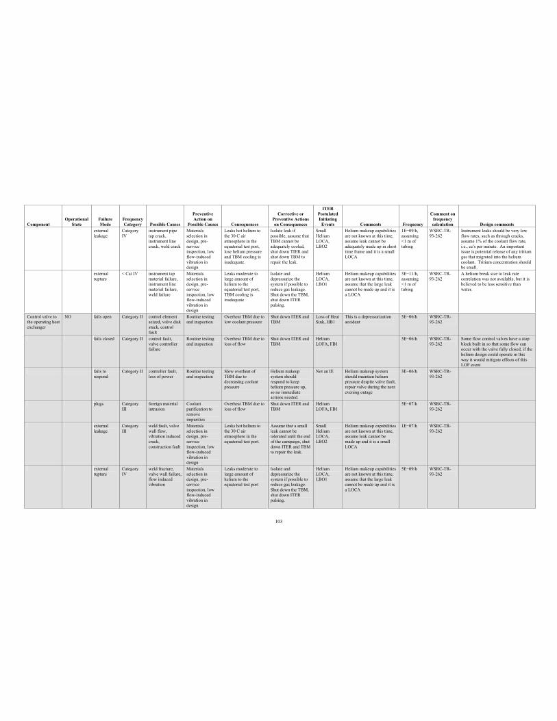
103
Component Operational
StateFailure Mode
Frequency Category Possible Causes
PreventiveAction on
Possible Causes Consequences
Corrective or Preventive Actions on Consequences
ITERPostulated Initiating
Events Comments Frequency
Comment on frequency calculation Design comments
external leakage
Category IV
instrument pipe tap crack, instrument line crack, weld crack
Materials selection in design, pre-serviceinspection, low flow-induced vibration in design
Leaks hot helium to the 30 C air atmosphere in the equatorial test port, lose helium pressure and TBM cooling is inadequate.
Isolate leak if possible, assume that TBM cannot be adequately cooled, shut down TIER and shut down TBM to repair the leak.
Small Helium LOCA,LBO2
Helium makeup capabilities are not known at this time, assume leak cannot be adequately made up in short time frame and it is a small LOCA
1E 09/h, assuming <1 m of tubing
WSRC-TR-93-262
Instrument leaks should be very low flow rates, such as through cracks, assume 1% of the coolant flow rate, i.e., cc's per minute. An important issue is potential release of any tritium gas that migrated into the helium coolant. Tritium concentration should be small.
external rupture
< Cat IV instrument tap material failure, instrument line material failure, weld failure
Materials selection in design, pre-serviceinspection, low flow-induced vibration in design
Leaks moderate to large amount of helium to the equatorial test port, TBM cooling is inadequate
Isolate and depressurize the system if possible to reduce gas leakage. Shut down the TBM, shut down ITER pulsing.
Helium LOCA,LBO1
Helium makeup capabilities are not known at this time, assume that the large leak cannot be made up and it is a LOCA
3E 11/h, assuming <1 m of tubing
WSRC-TR-93-262
A helium break size to leak rate correlation was not available, but it is believed to be less sensitive than water.
Control valve to the operating heat exchanger
NO fails open Category II control element seized, valve disk stuck, control fault
Routine testing and inspection
Overheat TBM due to low coolant pressure
Shut down ITER and TBM
Loss of Heat Sink, HB1
This is a depressurization accident
3E 06/h WSRC-TR-93-262
fails closed Category II control fault, valve controller failure
Routine testing and inspection
Overheat TBM due to loss of flow
Shut down ITER and TBM
Helium LOFA, FB1
3E 06/h WSRC-TR-93-262
Some flow control valves have a stop block built in so that some flow can occur with the valve fully closed, if the helium design could operate in this way it would mitigate effects of this LOF event
fails to respond
Category II controller fault, loss of power
Routine testing and inspection
Slow overheat of TBM due to decreasing coolant pressure
Helium makeup system should respond to keep helium pressure up, so no immediate actions needed.
Not an IE Helium makeup system should maintain helium pressure despite valve fault, repair valve during the next evening outage
3E 06/h WSRC-TR-93-262
plugs Category III
foreign material intrusion
Coolant purification to remove impurities
Overheat TBM due to loss of flow
Shut down ITER and TBM
Helium LOFA, FB1
5E 07/h WSRC-TR-93-262
externalleakage
Category III
weld fault, valve wall flaw, vibration induced crack,construction fault
Materials selection in design, pre-serviceinspection, low flow-induced vibration in design
Leaks hot helium to the 30 C air atmosphere in the equatorial test port.
Assume that a small leak cannot be tolerated until the end of the campaign, shut down ITER and TBM to repair the leak.
Small Helium LOCA,LBO2
Helium makeup capabilities are not known at this time, assume leak cannot be made up and it is a small LOCA
1E 07/h WSRC-TR-93-262
externalrupture
Category IV
weld fracture, valve wall failure, flow induced vibration
Materials selection in design, pre-serviceinspection, low flow-induced vibration in design
Leaks moderate to large amount of helium to the equatorial test port
Isolate and depressurize the system if possible to reduce gas leakage. Shut down the TBM, shut down ITER pulsing.
Helium LOCA,LBO1
Helium makeup capabilities are not known at this time, assume that the large leak cannot be made up and it is a LOCA
5E 09/h WSRC-TR-93-262
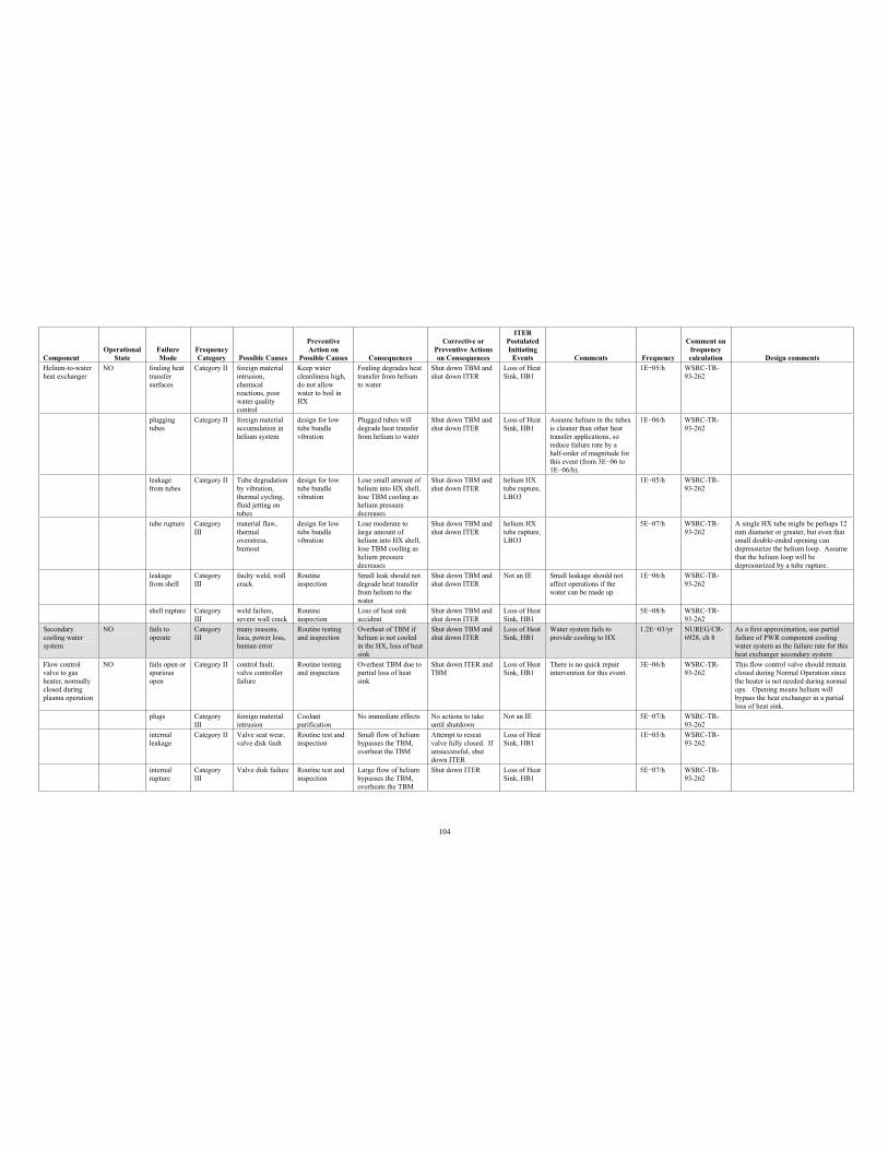
104
Component Operational
StateFailure Mode
Frequency Category Possible Causes
PreventiveAction on
Possible Causes Consequences
Corrective or Preventive Actions on Consequences
ITERPostulated Initiating
Events Comments Frequency
Comment on frequency calculation Design comments
Helium-to-water heat exchanger
NO fouling heat transfer surfaces
Category II foreign material intrusion, chemical reactions, poor water quality control
Keep water cleanliness high, do not allow water to boil in HX
Fouling degrades heat transfer from helium to water
Shut down TBM and shut down ITER
Loss of Heat Sink, HB1
1E 05/h WSRC-TR-93-262
plugging tubes
Category II foreign material accumulation in helium system
design for low tube bundle vibration
Plugged tubes will degrade heat transfer from helium to water
Shut down TBM and shut down ITER
Loss of Heat Sink, HB1
Assume helium in the tubes is cleaner than other heat transfer applications, so reduce failure rate by a half-order of magnitude for this event (from 3E 06 to 1E 06/h).
1E 06/h WSRC-TR-93-262
leakage from tubes
Category II Tube degradation by vibration, thermal cycling, fluid jetting on tubes
design for low tube bundle vibration
Lose small amount of helium into HX shell, lose TBM cooling as helium pressure decreases
Shut down TBM and shut down ITER
helium HX tube rupture, LBO3
1E 05/h WSRC-TR-93-262
tube rupture Category III
material flaw, thermal overstress, burnout
design for low tube bundle vibration
Lose moderate to large amount of helium into HX shell, lose TBM cooling as helium pressure decreases
Shut down TBM and shut down ITER
helium HX tube rupture, LBO3
5E 07/h WSRC-TR-93-262
A single HX tube might be perhaps 12 mm diameter or greater, but even that small double-ended opening can depressurize the helium loop. Assume that the helium loop will be depressurized by a tube rupture.
leakage from shell
Category III
faulty weld, wall crack
Routine inspection
Small leak should not degrade heat transfer from helium to the water
Shut down TBM and shut down ITER
Not an IE Small leakage should not affect operations if the water can be made up
1E 06/h WSRC-TR-93-262
shell rupture Category III
weld failure, severe wall crack
Routine inspection
Loss of heat sink accident
Shut down TBM and shut down ITER
Loss of Heat Sink, HB1
5E 08/h WSRC-TR-93-262
Secondary cooling water system
NO fails to operate
Category III
many reasons, loca, power loss, human error
Routine testing and inspection
Overheat of TBM if helium is not cooled in the HX, loss of heat sink
Shut down TBM and shut down ITER
Loss of Heat Sink, HB1
Water system fails to provide cooling to HX
1.2E 03/yr NUREG/CR-6928, ch 8
As a first approximation, use partial failure of PWR component cooling water system as the failure rate for this heat exchanger secondary system
Flow control valve to gas heater, normally closed during plasma operation
NO fails open or spuriousopen
Category II control fault, valve controller failure
Routine testing and inspection
Overheat TBM due to partial loss of heat sink
Shut down ITER and TBM
Loss of Heat Sink, HB1
There is no quick repair intervention for this event.
3E 06/h WSRC-TR-93-262
This flow control valve should remain closed during Normal Operation since the heater is not needed during normal ops. Opening means helium will bypass the heat exchanger in a partial loss of heat sink.
plugs Category III
foreign material intrusion
Coolant purification
No immediate effects No actions to take until shutdown
Not an IE 5E 07/h WSRC-TR-93-262
internal leakage
Category II Valve seat wear, valve disk fault
Routine test and inspection
Small flow of helium bypasses the TBM, overheat the TBM
Attempt to reseat valve fully closed. If unsuccessful, shut down ITER
Loss of Heat Sink, HB1
1E 05/h WSRC-TR-93-262
internal rupture
Category III
Valve disk failure Routine test and inspection
Large flow of helium bypasses the TBM, overheats the TBM
Shut down ITER Loss of Heat Sink, HB1
5E 07/h WSRC-TR-93-262
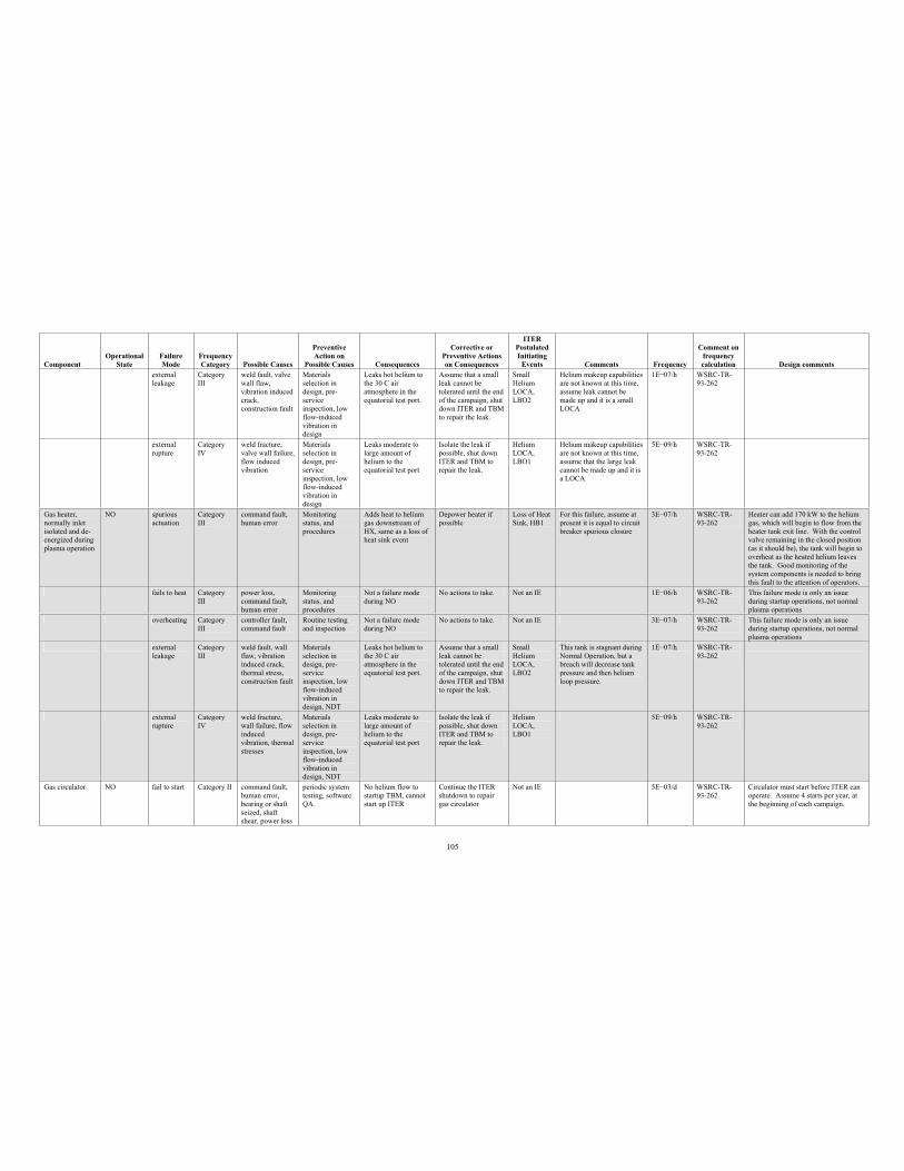
105
Component Operational
StateFailure Mode
Frequency Category Possible Causes
PreventiveAction on
Possible Causes Consequences
Corrective or Preventive Actions on Consequences
ITERPostulated Initiating
Events Comments Frequency
Comment on frequency calculation Design comments
external leakage
Category III
weld fault, valve wall flaw, vibration induced crack,construction fault
Materials selection in design, pre-serviceinspection, low flow-induced vibration in design
Leaks hot helium to the 30 C air atmosphere in the equatorial test port.
Assume that a small leak cannot be tolerated until the end of the campaign, shut down ITER and TBM to repair the leak.
Small Helium LOCA,LBO2
Helium makeup capabilities are not known at this time, assume leak cannot be made up and it is a small LOCA
1E 07/h WSRC-TR-93-262
external rupture
Category IV
weld fracture, valve wall failure, flow induced vibration
Materials selection in design, pre-serviceinspection, low flow-induced vibration in design
Leaks moderate to large amount of helium to the equatorial test port
Isolate the leak if possible, shut down ITER and TBM to repair the leak.
Helium LOCA,LBO1
Helium makeup capabilities are not known at this time, assume that the large leak cannot be made up and it is a LOCA
5E 09/h WSRC-TR-93-262
Gas heater, normally inlet isolated and de-energized during plasma operation
NO spuriousactuation
Category III
command fault, human error
Monitoring status, and procedures
Adds heat to helium gas downstream of HX, same as a loss of heat sink event
Depower heater if possible
Loss of Heat Sink, HB1
For this failure, assume at present it is equal to circuit breaker spurious closure
3E 07/h WSRC-TR-93-262
Heater can add 170 kW to the helium gas, which will begin to flow from the heater tank exit line. With the control valve remaining in the closed position (as it should be), the tank will begin to overheat as the heated helium leaves the tank. Good monitoring of the system components is needed to bring this fault to the attention of operators.
fails to heat Category III
power loss, command fault, human error
Monitoring status, and procedures
Not a failure mode during NO
No actions to take. Not an IE 1E 06/h WSRC-TR-93-262
This failure mode is only an issue during startup operations, not normal plasma operations
overheating Category III
controller fault, command fault
Routine testing and inspection
Not a failure mode during NO
No actions to take. Not an IE 3E 07/h WSRC-TR-93-262
This failure mode is only an issue during startup operations, not normal plasma operations
externalleakage
Category III
weld fault, wall flaw, vibration induced crack, thermal stress, construction fault
Materials selection in design, pre-serviceinspection, low flow-induced vibration in design, NDT
Leaks hot helium to the 30 C air atmosphere in the equatorial test port.
Assume that a small leak cannot be tolerated until the end of the campaign, shut down ITER and TBM to repair the leak.
Small Helium LOCA,LBO2
This tank is stagnant during Normal Operation, but a breach will decrease tank pressure and then helium loop pressure.
1E 07/h WSRC-TR-93-262
externalrupture
Category IV
weld fracture, wall failure, flow inducedvibration, thermal stresses
Materials selection in design, pre-serviceinspection, low flow-induced vibration in design, NDT
Leaks moderate to large amount of helium to the equatorial test port
Isolate the leak if possible, shut down ITER and TBM to repair the leak.
Helium LOCA,LBO1
5E 09/h WSRC-TR-93-262
Gas circulator NO fail to start Category II command fault, human error, bearing or shaft seized, shaft shear, power loss
periodic system testing, software QA
No helium flow to startup TBM, cannot start up ITER
Continue the ITER shutdown to repair gas circulator
Not an IE 5E 03/d WSRC-TR-93-262
Circulator must start before ITER can operate. Assume 4 starts per year, at the beginning of each campaign.
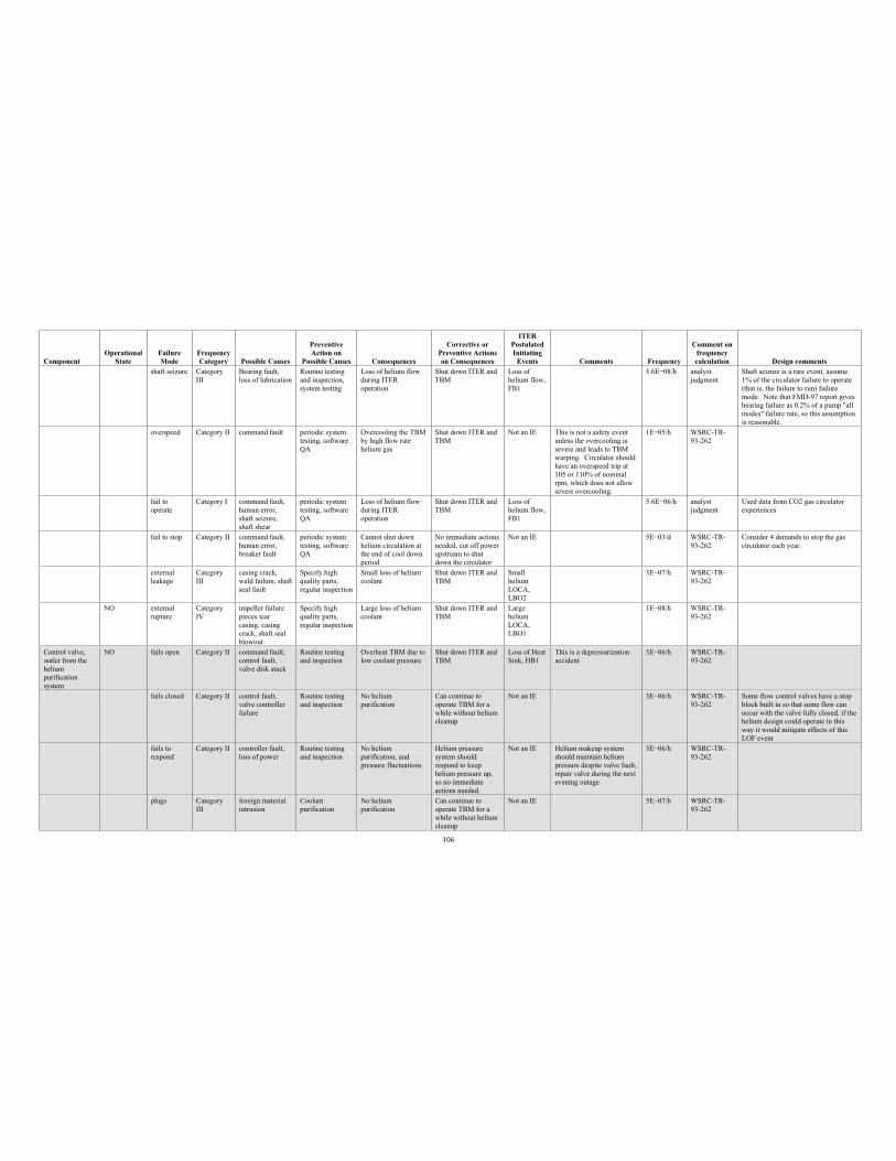
106
Component Operational
StateFailure Mode
Frequency Category Possible Causes
PreventiveAction on
Possible Causes Consequences
Corrective or Preventive Actions on Consequences
ITERPostulated Initiating
Events Comments Frequency
Comment on frequency calculation Design comments
shaft seizure Category III
Bearing fault, loss of lubrication
Routine testing and inspection, system testing
Loss of helium flow during ITER operation
Shut down ITER and TBM
Loss of helium flow, FB1
5.6E 08/h analyst judgment
Shaft seizure is a rare event, assume 1% of the circulator failure to operate (that is, the failure to run) failure mode. Note that FMD-97 report gives bearing failure as 0.2% of a pump "all modes" failure rate, so this assumption is reasonable.
overspeed Category II command fault periodic system testing, software QA
Overcooling the TBM by high flow rate helium gas
Shut down ITER and TBM
Not an IE This is not a safety event unless the overcooling is severe and leads to TBM warping. Circulator should have an overspeed trip at 105 or 110% of nominal rpm, which does not allow severe overcooling.
1E 05/h WSRC-TR-93-262
fail to operate
Category I command fault, human error, shaft seizure, shaft shear
periodic system testing, software QA
Loss of helium flow during ITER operation
Shut down ITER and TBM
Loss of helium flow, FB1
5.6E 06/h analyst judgment
Used data from CO2 gas circulator experiences
fail to stop Category II command fault, human error, breaker fault
periodic system testing, software QA
Cannot shut down helium circulation at the end of cool down period
No immediate actions needed, cut off power upstream to shut down the circulator
Not an IE 5E 03/d WSRC-TR-93-262
Consider 4 demands to stop the gas circulator each year.
external leakage
Category III
casing crack, weld failure, shaft seal fault
Specify high quality parts, regular inspection
Small loss of helium coolant
Shut down ITER and TBM
Small helium LOCA,LBO2
3E 07/h WSRC-TR-93-262
NO external rupture
Category IV
impeller failure pieces tear casing, casing crack, shaft seal blowout
Specify high quality parts, regular inspection
Large loss of helium coolant
Shut down ITER and TBM
Large helium LOCA,LBO1
1E 08/h WSRC-TR-93-262
Control valve, outlet from the helium purification system
NO fails open Category II command fault, control fault, valve disk stuck
Routine testing and inspection
Overheat TBM due to low coolant pressure
Shut down ITER and TBM
Loss of Heat Sink, HB1
This is a depressurization accident
3E 06/h WSRC-TR-93-262
fails closed Category II control fault, valve controller failure
Routine testing and inspection
No helium purification
Can continue to operate TBM for a while without helium cleanup
Not an IE 3E 06/h WSRC-TR-93-262
Some flow control valves have a stop block built in so that some flow can occur with the valve fully closed, if the helium design could operate in this way it would mitigate effects of this LOF event
fails to respond
Category II controller fault, loss of power
Routine testing and inspection
No helium purification, and pressure fluctuations
Helium pressure system should respond to keep helium pressure up, so no immediate actions needed.
Not an IE Helium makeup system should maintain helium pressure despite valve fault, repair valve during the next evening outage
3E 06/h WSRC-TR-93-262
plugs Category III
foreign material intrusion
Coolant purification
No helium purification
Can continue to operate TBM for a while without helium cleanup
Not an IE 5E 07/h WSRC-TR-93-262
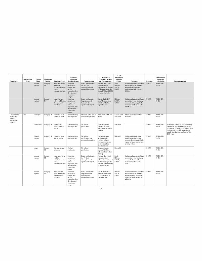
107
Component Operational
StateFailure Mode
Frequency Category Possible Causes
PreventiveAction on
Possible Causes Consequences
Corrective or Preventive Actions on Consequences
ITERPostulated Initiating
Events Comments Frequency
Comment on frequency calculation Design comments
externalleakage
Category III
weld fault, valve wall flaw, vibration induced crack,construction fault
Materials selection in design, pre-serviceinspection, low flow-induced vibration in design
Leaks hot helium to the 30 C air atmosphere in the equatorial test port.
Assume that a small leak cannot be tolerated until the end of the campaign, shut down ITER and TBM to repair the leak.
Small Helium LOCA,LBO2
Helium makeup capabilities are not known at this time, assume leak cannot be made up and it is a small LOCA
1E 07/h WSRC-TR-93-262
externalrupture
Category IV
weld fracture, valve wall failure, flow induced vibration
Materials selection in design, pre-serviceinspection, low flow-induced vibration in design
Leaks moderate to large amount of helium to the equatorial test port
Isolate the leak if possible, shut down ITER and TBM to repair the leak.
Helium LOCA,LBO1
Helium makeup capabilities are not known at this time, assume that the large leak cannot be made up and it is a LOCA
5E 09/h WSRC-TR-93-262
Control valve, inlet to the helium purification system
NO fails open Category II command fault, controller fault
Routine testing and inspection
Overheat TBM due to low coolant pressure
Shut down ITER and TBM
Loss of Heat Sink, HB1
This is a depressurization accident
3E 06/h WSRC-TR-93-262
fails closed Category II control fault, valve controller failure
Routine testing and inspection
No helium purification
Can continue to operate TBM for a while without helium cleanup
Not an IE 3E 06/h WSRC-TR-93-262
Some flow control valves have a stop block built in so that some flow can occur with the valve fully closed, if the helium design could operate in this way it would mitigate effects of this LOF event
fails to respond
Category II controller fault, loss of power
Routine testing and inspection
No helium purification, and pressure fluctuations
Helium pressure system should respond to keep helium pressure up, so no immediate actions needed.
Not an IE Helium makeup system should maintain helium pressure despite valve fault, repair valve during the next evening outage
3E 06/h WSRC-TR-93-262
plugs Category III
foreign material intrusion
Coolant purification
No helium purification
Can continue to operate TBM for a while without helium cleanup
Not an IE 5E 07/h WSRC-TR-93-262
external leakage
Category III
weld fault, valve wall flaw, vibration induced crack,construction fault
Materials selection in design, pre-serviceinspection, low flow-induced vibration in design
Leaks hot helium to the 30 C air atmosphere in the equatorial test port.
Assume that a small leak cannot be tolerated until the end of the campaign, shut down ITER and TBM to repair the leak.
Small Helium LOCA,LBO2
Helium makeup capabilities are not known at this time, assume leak cannot be made up and it is a small LOCA
1E 07/h WSRC-TR-93-262
external rupture
Category IV
weld fracture, valve wall failure, flow induced vibration
Materials selection in design, pre-serviceinspection, low flow-induced vibration in design
Leaks moderate to large amount of helium to the equatorial test port
Isolate the leak if possible, shut down ITER and TBM to repair the leak.
Helium LOCA,LBO1
Helium makeup capabilities are not known at this time, assume that the large leak cannot be made up and it is a LOCA
5E 09/h WSRC-TR-93-262
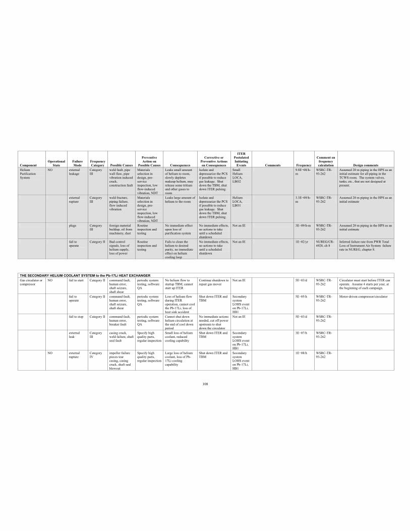
108
Component Operational
StateFailure Mode
Frequency Category Possible Causes
PreventiveAction on
Possible Causes Consequences
Corrective or Preventive Actions on Consequences
ITERPostulated Initiating
Events Comments Frequency
Comment on frequency calculation Design comments
Helium Purification System
NO externalleakage
Category III
weld fault, pipe wall flaw, pipe vibration induced crack,construction fault
Materials selection in design, pre-serviceinspection, low flow-induced vibration, NDT
Leaks small amount of helium to room, slowly depletes makeup helium, may release some tritium and other gases to room
Isolate and depressurize the PCS if possible to reduce gas leakage. Shut down the TBM, shut down ITER pulsing.
Small Helium LOCA,LBO2
9.8E 08/h-m
WSRC-TR-93-262
Assumed 20 m piping in the HPS as an initial estimate for all piping in the TCWS room. The system valves, tanks, etc., that are not designed at present.
externalrupture
Category III
weld fracture, piping failure, flow induced vibration
Materials selection in design, pre-serviceinspection, low flow-induced vibration, NDT
Leaks large amount of helium to the room
Isolate and depressurize the PCS if possible to reduce gas leakage. Shut down the TBM, shut down ITER pulsing.
Helium LOCA,LBO1
3.3E 09/h-m
WSRC-TR-93-262
Assumed 20 m piping in the HPS as an initial estimate
plugs Category III
foreign material buildup, oil from machinery, dust
Routine inspection and testing
No immediate effect upon loss of purification system
No immediate effects, no actions to take until a scheduled shutdown
Not an IE 3E 09/h-m WSRC-TR-93-262
Assumed 20 m piping in the HPS as an initial estimate
fail to operate
Category II Bad control signals, loss of helium supply, loss of power
Routine inspection and testing
Fails to clean the helium to desired purity, no immediate effect on helium cooling loop
No immediate effects, no actions to take until a scheduled shutdown
Not an IE 1E 02/yr NUREG/CR-6928, ch 8
Inferred failure rate from PWR Total Loss of Instrument Air System failure rate in NUREG, chapter 8.
THE SECONDARY HELIUM COOLANT SYSTEM to the Pb-17Li HEAT EXCHANGER Gas circulator or compressor
NO fail to start Category II command fault, human error, shaft seizure, shaft shear
periodic system testing, software QA
No helium flow to startup TBM, cannot start up ITER
Continue shutdown to repair gas mover
Not an IE 5E 03/d WSRC-TR-93-262
Circulator must start before ITER can operate. Assume 4 starts per year, at the beginning of each campaign.
fail to operate
Category II command fault, human error, shaft seizure, shaft shear
periodic system testing, software QA
Loss of helium flow during ITER operation, cannot cool the Pb-17Li, loss of heat sink accident
Shut down ITER and TBM
Secondary system LOHS event on Pb-17Li, HB1
5E 05/h WSRC-TR-93-262
Motor-driven compressor/circulator
fail to stop Category II command fault, human error, breaker fault
periodic system testing, software QA
Cannot shut down helium circulation at the end of cool down period
No immediate actions needed, cut off power upstream to shut down the circulator
Not an IE 5E 03/d WSRC-TR-93-262
external leak
Category III
casing crack, weld failure, shaft seal fault
Specify high quality parts, regular inspection
Small loss of helium coolant, reduced cooling capability
Shut down ITER and TBM
Secondary system LOHS event on Pb-17Li, HB1
3E 07/h WSRC-TR-93-262
NO external rupture
Category IV
impeller failure pieces tear casing, casing crack, shaft seal blowout
Specify high quality parts, regular inspection
Large loss of helium coolant, loss of Pb-17Li cooling capability
Shut down ITER and TBM
Secondary system LOHS event on Pb-17Li, HB1
1E 08/h WSRC-TR-93-262
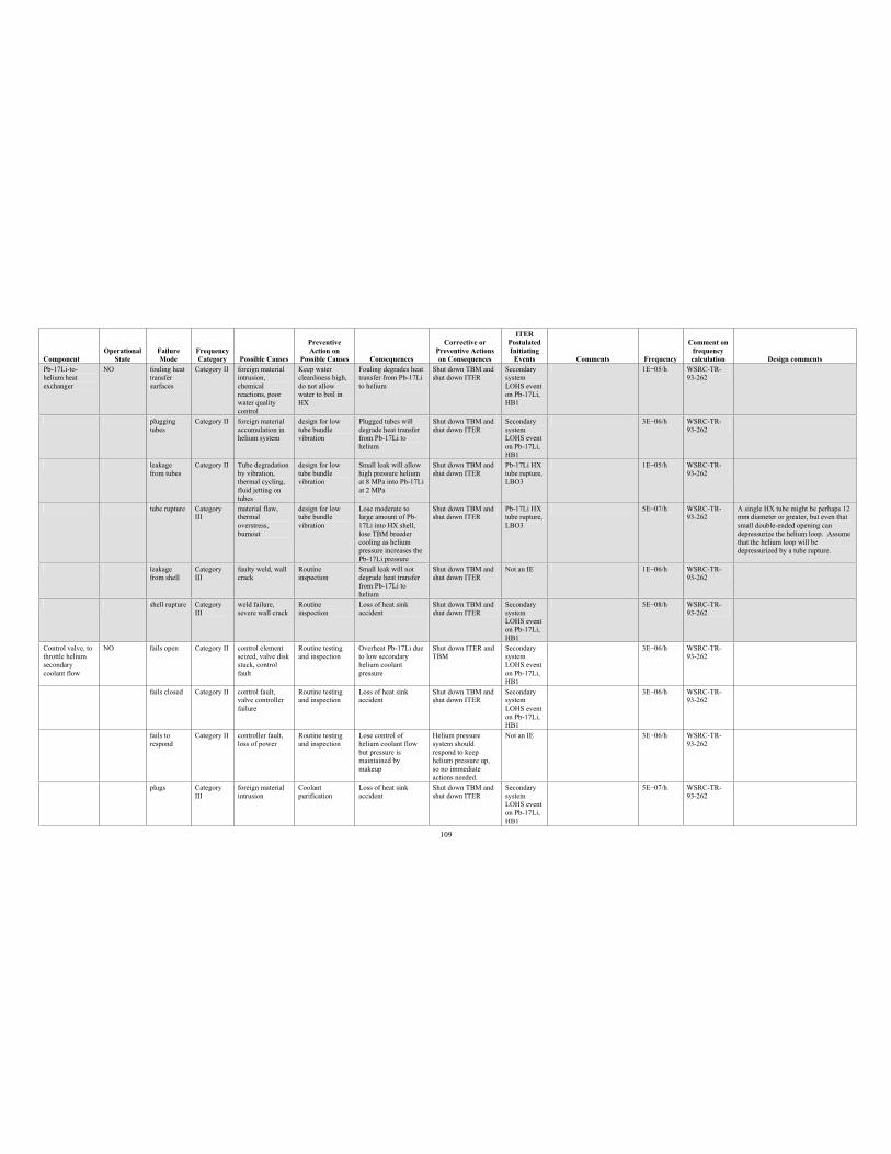
109
Component Operational
StateFailure Mode
Frequency Category Possible Causes
PreventiveAction on
Possible Causes Consequences
Corrective or Preventive Actions on Consequences
ITERPostulated Initiating
Events Comments Frequency
Comment on frequency calculation Design comments
Pb-17Li-to-helium heat exchanger
NO fouling heat transfer surfaces
Category II foreign material intrusion, chemical reactions, poor water quality control
Keep water cleanliness high, do not allow water to boil in HX
Fouling degrades heat transfer from Pb-17Li to helium
Shut down TBM and shut down ITER
Secondary system LOHS event on Pb-17Li, HB1
1E 05/h WSRC-TR-93-262
plugging tubes
Category II foreign material accumulation in helium system
design for low tube bundle vibration
Plugged tubes will degrade heat transfer from Pb-17Li to helium
Shut down TBM and shut down ITER
Secondary system LOHS event on Pb-17Li, HB1
3E 06/h WSRC-TR-93-262
leakagefrom tubes
Category II Tube degradation by vibration, thermal cycling, fluid jetting on tubes
design for low tube bundle vibration
Small leak will allow high pressure helium at 8 MPa into Pb-17Li at 2 MPa
Shut down TBM and shut down ITER
Pb-17Li HX tube rupture, LBO3
1E 05/h WSRC-TR-93-262
tube rupture Category III
material flaw, thermal overstress, burnout
design for low tube bundle vibration
Lose moderate to large amount of Pb-17Li into HX shell, lose TBM breeder cooling as helium pressure increases the Pb-17Li pressure
Shut down TBM and shut down ITER
Pb-17Li HX tube rupture, LBO3
5E 07/h WSRC-TR-93-262
A single HX tube might be perhaps 12 mm diameter or greater, but even that small double-ended opening can depressurize the helium loop. Assume that the helium loop will be depressurized by a tube rupture.
leakagefrom shell
Category III
faulty weld, wall crack
Routine inspection
Small leak will not degrade heat transfer from Pb-17Li to helium
Shut down TBM and shut down ITER
Not an IE 1E 06/h WSRC-TR-93-262
shell rupture Category III
weld failure, severe wall crack
Routine inspection
Loss of heat sink accident
Shut down TBM and shut down ITER
Secondary system LOHS event on Pb-17Li, HB1
5E 08/h WSRC-TR-93-262
Control valve, to throttle helium secondary coolant flow
NO fails open Category II control element seized, valve disk stuck, control fault
Routine testing and inspection
Overheat Pb-17Li due to low secondary helium coolant pressure
Shut down ITER and TBM
Secondary system LOHS event on Pb-17Li, HB1
3E 06/h WSRC-TR-93-262
fails closed Category II control fault, valve controller failure
Routine testing and inspection
Loss of heat sink accident
Shut down TBM and shut down ITER
Secondary system LOHS event on Pb-17Li, HB1
3E 06/h WSRC-TR-93-262
fails to respond
Category II controller fault, loss of power
Routine testing and inspection
Lose control of helium coolant flow but pressure is maintained by makeup
Helium pressure system should respond to keep helium pressure up, so no immediate actions needed.
Not an IE 3E 06/h WSRC-TR-93-262
plugs Category III
foreign material intrusion
Coolant purification
Loss of heat sink accident
Shut down TBM and shut down ITER
Secondary system LOHS event on Pb-17Li, HB1
5E 07/h WSRC-TR-93-262
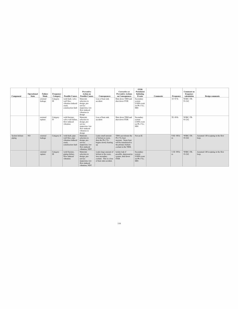
110
Component Operational
StateFailure Mode
Frequency Category Possible Causes
PreventiveAction on
Possible Causes Consequences
Corrective or Preventive Actions on Consequences
ITERPostulated Initiating
Events Comments Frequency
Comment on frequency calculation Design comments
external leakage
Category III
weld fault, valve wall flaw, vibration induced crack,construction fault
Materials selection in design, pre-serviceinspection, low flow-induced vibration in design
Loss of heat sink accident
Shut down TBM and shut down ITER
Secondary system LOHS event on Pb-17Li, HB1
1E 07/h WSRC-TR-93-262
external rupture
Category IV
weld fracture, valve wall failure, flow induced vibration
Materials selection in design, pre-serviceinspection, low flow-induced vibration in design
Loss of heat sink accident
Shut down TBM and shut down ITER
Secondary system LOHS event on Pb-17Li, HB1
5E 09/h WSRC-TR-93-262
System helium piping
NO externalleakage
Category II weld fault, pipe wall flaw, pipe vibration induced crack,construction fault
Materials selection in design, pre-serviceinspection, low flow-induced vibration, NDT
Leaks small amount of helium to room, then the Pb-17Li begins slowly heating up.
TBM can tolerate the Pb-17Li heat increase. Some heat will be transferred to the primary helium coolant in the TBM.
Not an IE 9.8E 08/h-m
WSRC-TR-93-262
Assumed 140 m piping in the flow loop.
externalrupture
Category III
weld fracture, piping failure, flow induced vibration
Materials selection in design, pre-serviceinspection, low flow-induced vibration, NDT
Leaks large amount of helium to the room, lose secondary coolant. This is a loss of heat sink accident.
Isolate leak if possible, depressurize system, shut down ITER
Secondary system LOHS event on Pb-17Li, HB1
3.3E 09/h-m
WSRC-TR-93-262
Assumed 140 m piping in the flow loop.
111
Appendix C
Preliminary Failure Modes and Effects Analysis for the TBM Module Box
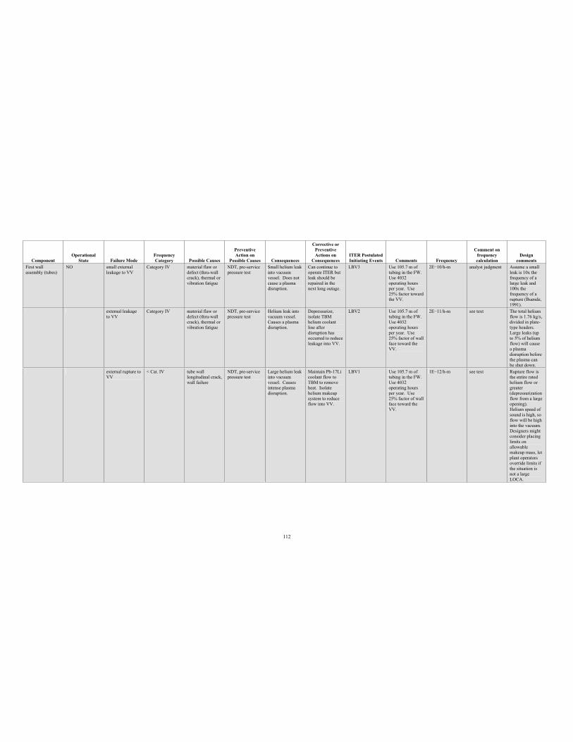
112
Component Operational
State Failure Mode Frequency Category Possible Causes
PreventiveAction on
Possible Causes Consequences
Corrective or PreventiveActions on
Consequences ITER Postulated Initiating Events Comments Frequency
Comment on frequency calculation
Design comments
First wall assembly (tubes)
NO small external leakage to VV
Category IV material flaw or defect (thru-wall crack), thermal or vibration fatigue
NDT, pre-service pressure test
Small helium leak into vacuum vessel. Does not cause a plasma disruption.
Can continue to operate ITER but leak should be repaired in the next long outage.
LBV3 Use 105.7 m of tubing in the FW. Use 4032 operating hours per year. Use 25% factor toward the VV.
2E 10/h-m analyst judgment Assume a small leak is 10x the frequency of a large leak and 100x the frequency of a rupture (Buende, 1991).
external leakage to VV
Category IV material flaw or defect (thru-wall crack), thermal or vibration fatigue
NDT, pre-service pressure test
Helium leak into vacuum vessel. Causes a plasma disruption.
Depressurize, isolate TBM helium coolant line after disruption has occurred to reduce leakage into VV.
LBV2 Use 105.7 m of tubing in the FW. Use 4032 operating hours per year. Use 25% factor of wall face toward the VV.
2E 11/h-m see text The total helium flow is 1.76 kg/s, divided in plate-type headers. Large leaks (up to 5% of helium flow) will cause a plasma disruption before the plasma can be shut down.
external rupture to VV
< Cat. IV tube wall longitudinal crack, wall failure
NDT, pre-service pressure test
Large helium leak into vacuum vessel. Causes intense plasma disruption.
Maintain Pb-17Li coolant flow to TBM to remove heat. Isolate helium makeup system to reduce flow into VV.
LBV1 Use 105.7 m of tubing in the FW. Use 4032 operating hours per year. Use 25% factor of wall face toward the VV.
1E 12/h-m see text Rupture flow is the entire rated helium flow or greater(depressurization flow from a large opening). Helium speed of sound is high, so flow will be high into the vacuum. Designers might consider placing limits on allowable makeup mass, let plant operators override limits if the situation is not a large LOCA.
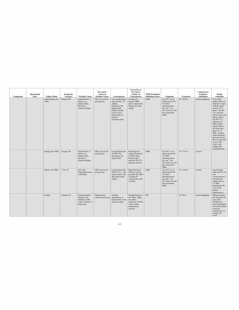
113
Component Operational
State Failure Mode Frequency Category Possible Causes
PreventiveAction on
Possible Causes Consequences
Corrective or PreventiveActions on
Consequences ITER Postulated Initiating Events Comments Frequency
Comment on frequency calculation
Design comments
small leakage into TBM
Category III material flaw or defect (e.g., pinhole leak), thermal or vibration fatigue
NDT, pre-service pressure test
Very small helium leak into Pb-17Li, slightly pressurizes the liquid metal. Helium should evolve out of liquid metal in pump or expansion tank.
Continue to operate TBM, plan to repair leak during next long outage.
LBB3 Use 105.7 m of tubing in the FW. Use 4032 operating hours per year. Use 25% factor of wall face toward the TBM.
2E 10/h-m analyst judgment Very small helium leaks are difficult to sense with the usual sensors (T, P, flow). The Pb-17Li pressure will increase with helium inflow. The Pb-17Li operates at 2 MPa and the rupture disk to the drain tank opens at 3.5 MPa. Assume small inleakage does not elevate Pb-17Li pressure to any value close to the rupture disk actuation point.
leakage into TBM Category III material flaw or defect (e.g., pinhole leak), thermal or vibration fatigue
NDT, pre-service pressure test
Large helium leak into Pb-17Li, pressurizes the liquid metal.
Must begin an orderly shut down of ITER when helium leak is noted by Pb-17Li pressure increase.
LBB2 Use 105.7 m of tubing in the FW. Use 4032 operating hours per year. Use 25% factor of wall face toward the TBM.
2E 11/h-m see text
rupture into TBM < Cat. IV tube wall longitudinal crack, wall failure
NDT, pre-service pressure test
Large helium leak into Pb-17Li. The rupture disk to the drain tank opens rapidly.
Must shut down ITER as soon as possible, the TBM is losing all cooling and could overheat.
LBB1 Use 105.7 m of tubing in the FW. Use 4032 operating hours per year. Use 25% factor of wall face toward the TBM.
1E 12/h-m see text Large helium leak into Pb-17Li willoverpressurize it and open the rupture disk at 3.5 MPa, draining the Pb-17Li as the helium depressurizes.
fouling Category IV foreign material intrusion and buildup on tube walls, moisture in helium gas
Helium purity control, gas drying
Gradual degradation of heat transfer to the helium coolant
Gradual heatup of the TBM. Begin an orderly shutdown of ITER when coolant temperatures increase.
FB2 1E 04/yr analyst judgment Helium systems are reputed to be very clean. HTGRs have only had graphite dust and moisture concerns. Assume this is a category IV event.
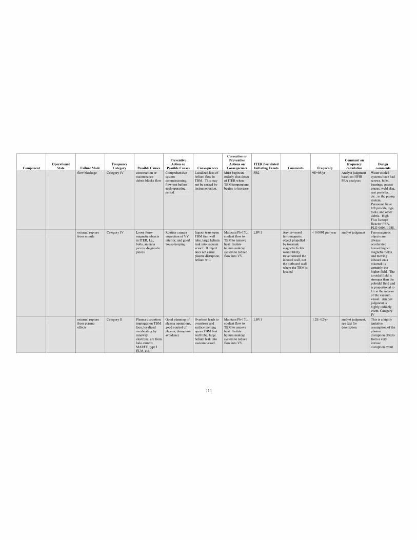
114
Component Operational
State Failure Mode Frequency Category Possible Causes
PreventiveAction on
Possible Causes Consequences
Corrective or PreventiveActions on
Consequences ITER Postulated Initiating Events Comments Frequency
Comment on frequency calculation
Design comments
flow blockage Category IV construction or maintenance debris blocks flow
Comprehensive system commissioning, flow test before each operating period.
Localized loss of helium flow in TBM. This may not be sensed by instrumentation.
Must begin an orderly shut down of ITER when TBM temperature begins to increase.
FB2 9E 05/yr Analyst judgment based on HFIR PRA analyses
Water cooled systems have had screws, bolts, bearings, gasket pieces, weld slag, rust particles, etc., in the piping system. Personnel have left pencils, rags, tools, and other debris. High Flux Isotope Reactor PRA, PLG-0604, 1988.
external rupture from missile
Category IV Loose ferro-magnetic objects in ITER, I.e., bolts, antenna pieces, diagnostic pieces
Routine camera inspection of VV interior, and good house-keeping
Impact tears open TBM first wall tube, large helium leak into vacuum vessel. If object does not cause plasma disruption, helium will.
Maintain Pb-17Li coolant flow to TBM to remove heat. Isolate helium makeup system to reduce flow into VV.
LBV1 Any in-vessel ferromagnetic object propelled by tokamak magnetic fields would likely travel toward the inboard wall, not the outboard wall where the TBM is located
< 0.0001 per year analyst judgment Ferromagnetic objects are alwaysacceleratedtoward higher magnetic fields, and moving inboard on a tokamak is certainly the higher field. The toroidal field is stronger than the poloidal field and is proportional to 1/r in the interior of the vacuum vessel. Analyst judgment is highly unlikely event, Category IV
external rupture from plasma effects
Category II Plasma disruption impinges on TBM face, localized overheating by runaway electrons, arc from halo current, MARFE, type I ELM, etc.
Good planning of plasma operations, good control of plasma, disruption avoidance
Overheat leads to overstress and surface melting opens TBM first wall tube, large helium leak into vacuum vessel.
Maintain Pb-17Li coolant flow to TBM to remove heat. Isolate helium makeup system to reduce flow into VV.
LBV1 1.2E 02/yr analyst judgment, see text for description
This is a highly tentative assumption of the plasma disruption effects from a very intense disruption event.
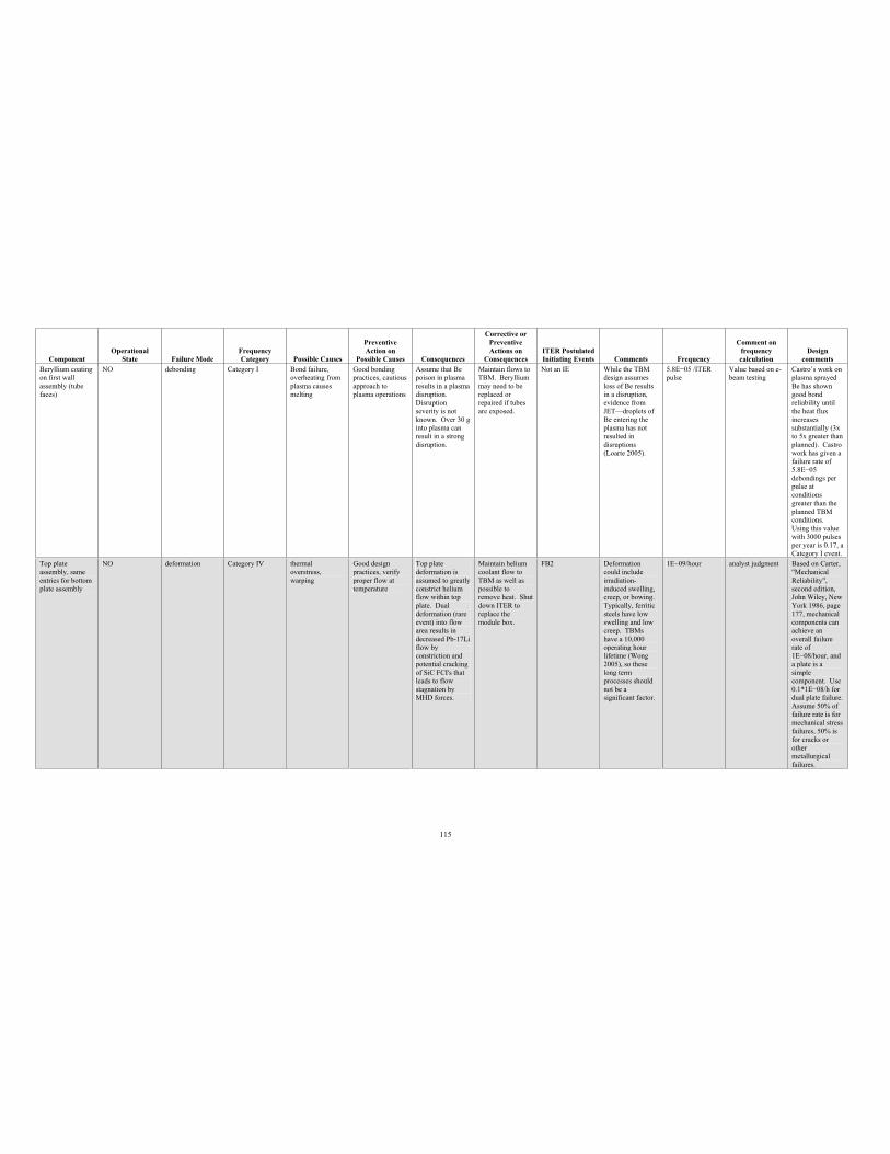
115
Component Operational
State Failure Mode Frequency Category Possible Causes
PreventiveAction on
Possible Causes Consequences
Corrective or PreventiveActions on
Consequences ITER Postulated Initiating Events Comments Frequency
Comment on frequency calculation
Design comments
Beryllium coating on first wall assembly (tube faces)
NO debonding Category I Bond failure, overheating from plasma causes melting
Good bonding practices, cautious approach to plasma operations
Assume that Be poison in plasma results in a plasma disruption. Disruption severity is not known. Over 30 g into plasma can result in a strong disruption.
Maintain flows to TBM. Beryllium may need to be replaced or repaired if tubes are exposed.
Not an IE While the TBM design assumes loss of Be results in a disruption, evidence from JET—droplets of Be entering the plasma has not resulted in disruptions (Loarte 2005).
5.8E 05 /ITER pulse
Value based on e-beam testing
Castro’s work on plasma sprayed Be has shown good bond reliability until the heat flux increases substantially (3x to 5x greater than planned). Castro work has given a failure rate of 5.8E 05 debondings per pulse at conditions greater than the planned TBM conditions. Using this value with 3000 pulses per year is 0.17, a Category I event.
Top plate assembly, same entries for bottom plate assembly
NO deformation Category IV thermal overstress, warping
Good design practices, verify proper flow at temperature
Top plate deformation is assumed to greatly constrict helium flow within top plate. Dual deformation (rare event) into flow area results in decreased Pb-17Li flow by constriction and potential cracking of SiC FCI's that leads to flow stagnation by MHD forces.
Maintain helium coolant flow to TBM as well as possible to remove heat. Shut down ITER to replace the module box.
FB2 Deformation could include irradiation-induced swelling, creep, or bowing. Typically, ferritic steels have low swelling and low creep. TBMs have a 10,000 operating hour lifetime (Wong 2005), so these long term processes should not be a significant factor.
1E 09/hour analyst judgment Based on Carter, "MechanicalReliability", second edition, John Wiley, New York 1986, page 177, mechanical components can achieve an overall failure rate of 1E 08/hour, and a plate is a simple component. Use 0.1*1E 08/h for dual plate failure. Assume 50% of failure rate is for mechanical stress failures, 50% is for cracks or other metallurgical failures.
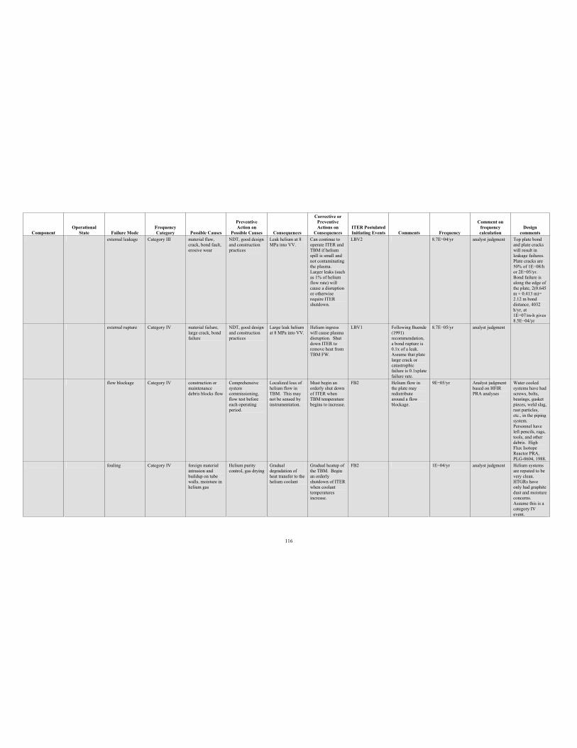
116
Component Operational
State Failure Mode Frequency Category Possible Causes
PreventiveAction on
Possible Causes Consequences
Corrective or PreventiveActions on
Consequences ITER Postulated Initiating Events Comments Frequency
Comment on frequency calculation
Design comments
external leakage Category III material flaw, crack, bond fault, erosive wear
NDT, good design and construction practices
Leak helium at 8 MPa into VV.
Can continue to operate ITER and TBM if helium spill is small and not contaminating the plasma. Larger leaks (such as 1% of helium flow rate) will cause a disruption or otherwise require ITER shutdown.
LBV2 8.7E 04/yr analyst judgment Top plate bond and plate cracks will result in leakage failures. Plate cracks are 50% of 1E 08/h or 2E 05/yr. Bond failure is along the edge of the plate, 2(0.645 m + 0.413 m)= 2.12 m bond distance, 4032 h/yr, at 1E 07/m-h gives 8.5E 04/yr
external rupture Category IV material failure, large crack, bond failure
NDT, good design and construction practices
Large leak helium at 8 MPa into VV.
Helium ingress will cause plasma disruption. Shut down ITER to remove heat from TBM FW.
LBV1 Following Buende (1991) recommendation, a bond rupture is 0.1x of a leak. Assume that plate large crack or catastrophicfailure is 0.1xplate failure rate.
8.7E 05/yr analyst judgment
flow blockage Category IV construction or maintenance debris blocks flow
Comprehensive system commissioning, flow test before each operating period.
Localized loss of helium flow in TBM. This may not be sensed by instrumentation.
Must begin an orderly shut down of ITER when TBM temperature begins to increase.
FB2 Helium flow in the plate may redistribute around a flow blockage.
9E 05/yr Analyst judgment based on HFIR PRA analyses
Water cooled systems have had screws, bolts, bearings, gasket pieces, weld slag, rust particles, etc., in the piping system. Personnel have left pencils, rags, tools, and other debris. High Flux Isotope Reactor PRA, PLG-0604, 1988.
fouling Category IV foreign material intrusion and buildup on tube walls, moisture in helium gas
Helium purity control, gas drying
Gradual degradation of heat transfer to the helium coolant
Gradual heatup of the TBM. Begin an orderly shutdown of ITER when coolant temperatures increase.
FB2 1E 04/yr analyst judgment Helium systems are reputed to be very clean. HTGRs have only had graphite dust and moisture concerns. Assume this is a category IV event.
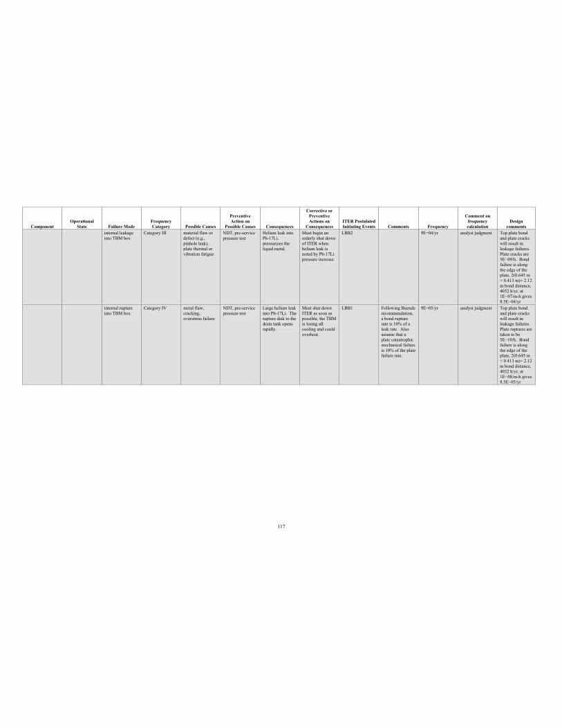
117
Component Operational
State Failure Mode Frequency Category Possible Causes
PreventiveAction on
Possible Causes Consequences
Corrective or PreventiveActions on
Consequences ITER Postulated Initiating Events Comments Frequency
Comment on frequency calculation
Design comments
internal leakage into TBM box
Category III material flaw or defect (e.g., pinhole leak), plate thermal or vibration fatigue
NDT, pre-service pressure test
Helium leak into Pb-17Li,pressurizes the liquid metal.
Must begin an orderly shut down of ITER when helium leak is noted by Pb-17Li pressure increase.
LBB2 9E 04/yr analyst judgment Top plate bond and plate cracks will result in leakage failures. Plate cracks are 5E 09/h. Bond failure is along the edge of the plate, 2(0.645 m + 0.413 m)= 2.12 m bond distance, 4032 h/yr, at 1E 07/m-h gives 8.5E 04/yr
internal rupture into TBM box
Category IV metal flaw, cracking, overstress failure
NDT, pre-service pressure test
Large helium leak into Pb-17Li. The rupture disk to the drain tank opens rapidly.
Must shut down ITER as soon as possible, the TBM is losing all cooling and could overheat.
LBB1 Following Buende recommendation, a bond rupture rate is 10% of a leak rate. Also assume that a plate catastrophic mechanical failure is 10% of the plate failure rate.
9E 05/yr analyst judgment Top plate bond and plate cracks will result in leakage failures. Plate ruptures are taken to be 5E 10/h. Bond failure is along the edge of the plate, 2(0.645 m + 0.413 m)= 2.12 m bond distance, 4032 h/yr, at 1E 08/m-h gives 8.5E 05/yr
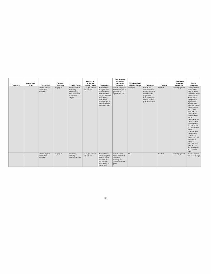
118
Component Operational
State Failure Mode Frequency Category Possible Causes
PreventiveAction on
Possible Causes Consequences
Corrective or PreventiveActions on
Consequences ITER Postulated Initiating Events Comments Frequency
Comment on frequency calculation
Design comments
internal leakage within plate assembly
Category III material flaw or defect (e.g., pinhole leak), plate fin thermal or vibration fatigue
NDT, pre-service pressure test
Helium lateral leakage within plate must still enter one of the two grid plates to leave the top plate. Some cooling might be reduced in some parts of the plate.
Effects are judged to be minor, not a problem to operate the TBM
Not an IE Helium will continue to flow through the plate assembly, and judgment is mostly adequate cooling to avoid plate deformation.
1E 07/h analyst judgment Twenty one fins, each 0.4 m long. A steam turbine has stator blades to direct steam. For a high pressure superheatedsteam turbine, there could be 48 blades per row and 15 rows. EPRI-AP-2071 gave a steam turbine failure rate of 1.83E 04/h, and 1.81% of faults involve blades, or a failure rate of 3.3E 06/h for blades. Representative high pressure turbine is 48 blades/row x 15 rows is 720 blades, or 4.6E 09/blade-hour. For 21 fins, that would be 1E 07/fin-hour.
internal rupture within plate assembly
Category III metal flaw, cracking, overstress failure
NDT, pre-service pressure test
Helium lateral flow in the plate must still enter one of the two grid plates to leave the top or bottom plate.
Effects could result in thermal overstress, warping and deformation of the plate.
FB2 1E 08/h analyst judgment Assume rupture is 0.1x of leakage
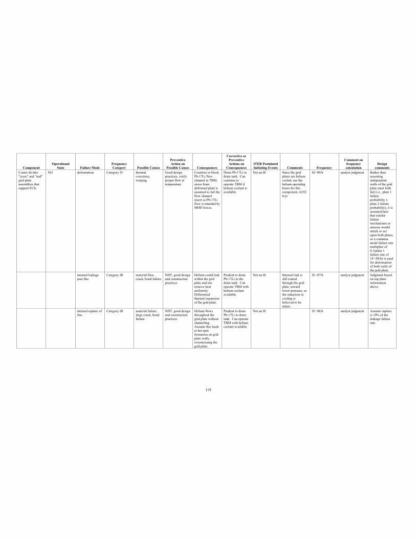
119
Component Operational
State Failure Mode Frequency Category Possible Causes
PreventiveAction on
Possible Causes Consequences
Corrective or PreventiveActions on
Consequences ITER Postulated Initiating Events Comments Frequency
Comment on frequency calculation
Design comments
Center divider "cross" and "end" grid plate assemblies that support FCIs
NO deformation Category IV thermal overstress, warping
Good design practices, verify proper flow at temperature
Constrict or block Pb-17Li flow channel in TBM, stress from deformed plate is assumed to fail the flow channel insert so Pb-17Li flow is retarded by MHD forces.
Drain Pb-17Li to drain tank. Can continue to operate TBM if helium coolant is available.
Not an IE Since the grid plates are helium cooled, use the helium operating hours for this component, 4,032 h/yr
1E 09/h analyst judgment Rather than assuming independent walls of the grid plate must both fail (i.e., plate 1 failureprobability x plate 2 failure probability), it is assumed here that similar failuremechanisms or stresses would attack or act upon both plates, so a common mode failure rate multiplier of 0.1(plate 1 failure rate of 1E 08/h) is used for deformation of both walls of the grid plate.
internal leakage past fins
Category III material flaw, crack, bond failure
NDT, good design and construction practices
Helium could leak within the grid plate and not remove heat uniformly. Differential thermal expansion of the grid plate.
Prudent to drain Pb-17Li to the drain tank. Can operate TBM with helium coolant available.
Not an IE Internal leak is still routed through the grid plate, toward lower pressure, so the reduction in cooling is believed to be minor.
1E 07/h analyst judgment Judgment based on top plate information above.
internal rupture of fins
Category III material failure, large crack, bond failure
NDT, good design and construction practices
Helium flows throughout the grid plate without channeling.Assume this leads to hot spot formation on grid plate walls, overstressing the grid plate.
Prudent to drain Pb-17Li to drain tank. Can operate TBM with helium coolant available.
Not an IE 1E 08/h analyst judgment Assume rupture is 10% of the leakage failure rate.
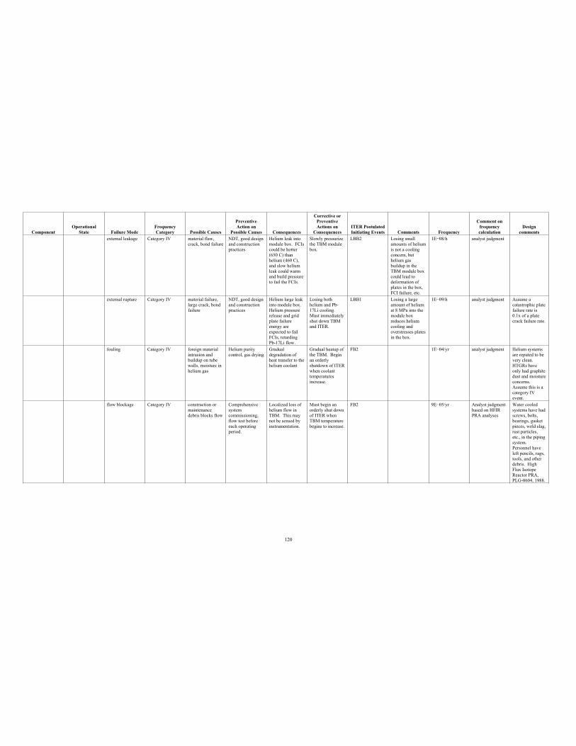
120
Component Operational
State Failure Mode Frequency Category Possible Causes
PreventiveAction on
Possible Causes Consequences
Corrective or PreventiveActions on
Consequences ITER Postulated Initiating Events Comments Frequency
Comment on frequency calculation
Design comments
external leakage Category IV material flaw, crack, bond failure
NDT, good design and construction practices
Helium leak into module box. FCIs could be hotter (650 C) than helium (460 C), and slow helium leak could warm and build pressure to fail the FCIs.
Slowly pressurize the TBM module box.
LBB2 Losing small amounts of helium is not a cooling concern, but helium gas buildup in the TBM module box could lead to deformation of plates in the box, FCI failure, etc.
1E 08/h analyst judgment
external rupture Category IV material failure, large crack, bond failure
NDT, good design and construction practices
Helium large leak into module box. Helium pressure release and grid plate failure energy are expected to fail FCIs, retarding Pb-17Li flow.
Losing both helium and Pb-17Li cooling. Must immediately shut down TBM and ITER.
LBB1 Losing a large amount of helium at 8 MPa into the module box reduces helium cooling and overstresses plates in the box.
1E 09/h analyst judgment Assume a catastrophic plate failure rate is 0.1x of a plate crack failure rate.
fouling Category IV foreign material intrusion and buildup on tube walls, moisture in helium gas
Helium purity control, gas drying
Gradual degradation of heat transfer to the helium coolant
Gradual heatup of the TBM. Begin an orderly shutdown of ITER when coolant temperatures increase.
FB2 1E 04/yr analyst judgment Helium systems are reputed to be very clean. HTGRs have only had graphite dust and moisture concerns. Assume this is a category IV event.
flow blockage Category IV construction or maintenance debris blocks flow
Comprehensive system commissioning, flow test before each operating period.
Localized loss of helium flow in TBM. This may not be sensed by instrumentation.
Must begin an orderly shut down of ITER when TBM temperature begins to increase.
FB2 9E 05/yr Analyst judgment based on HFIR PRA analyses
Water cooled systems have had screws, bolts, bearings, gasket pieces, weld slag, rust particles, etc., in the piping system. Personnel have left pencils, rags, tools, and other debris. High Flux Isotope Reactor PRA, PLG-0604, 1988.
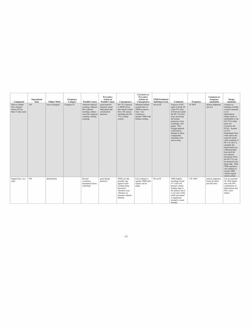
121
Component Operational
State Failure Mode Frequency Category Possible Causes
PreventiveAction on
Possible Causes Consequences
Corrective or PreventiveActions on
Consequences ITER Postulated Initiating Events Comments Frequency
Comment on frequency calculation
Design comments
Silicon carbide flow channel inserts (FCIs), three U-duct units
NO loss of integrity Category IV vibration induced cracking, inherent flaw induced cracking, surface wear flaw induced cracking, fretting cracking
good material selection, good fabrication and construction practices
Pb-17Li exposed to MHD forces that retard coolant flow, SiC pieces intruding into Pb-17Li cooling system.
Maintain helium coolant flow to TBM to remove heat. Can continue to operate TBM with helium cooling.
Not an IE If pieces of SiC spall or break off of the FCI, they will travel around the Pb-17Li flow loop, traversing the tritium permeator, heat exchanger, and pump. This foreign material could lead to damage in these components, including wear and scoring.
1E 08/h analyst judgment, see text
Assume no bending of brittle ceramic material, so no deformation failure mode is attributable to the SiC FCIs (other parts can overstress the FCIs). Assume no FCI detachment from walls unless the material cracks. After cracking, if Pb-17Li flow is retarded, the liquid metal can withstand high heat until the next plasma downtime when the Pb-17Li can be drained to the drain tank. Then ITER operators can continue to run the TBM without liquid metal coolant.
Support key, two units
NO deformation thermal overstress, mechanical stress, weld fault
good design practices
TBM can slip, possibly sag against water cooling frame. Increased vibration wear, vibration on structure reduces lifetime.
Can continue to operate TBM until repairs can be made.
Not an IE TBM slightly receding toward VV wall will present a frame leading edge to the plasma, but it is not clear if this small movement is significant enough to cause damage.
1.5E 08/h analyst judgment, based on metal part fail rates
Use an assumed 3E 08/h failure rate with 50% contribution of deformation and 50% crack failure.
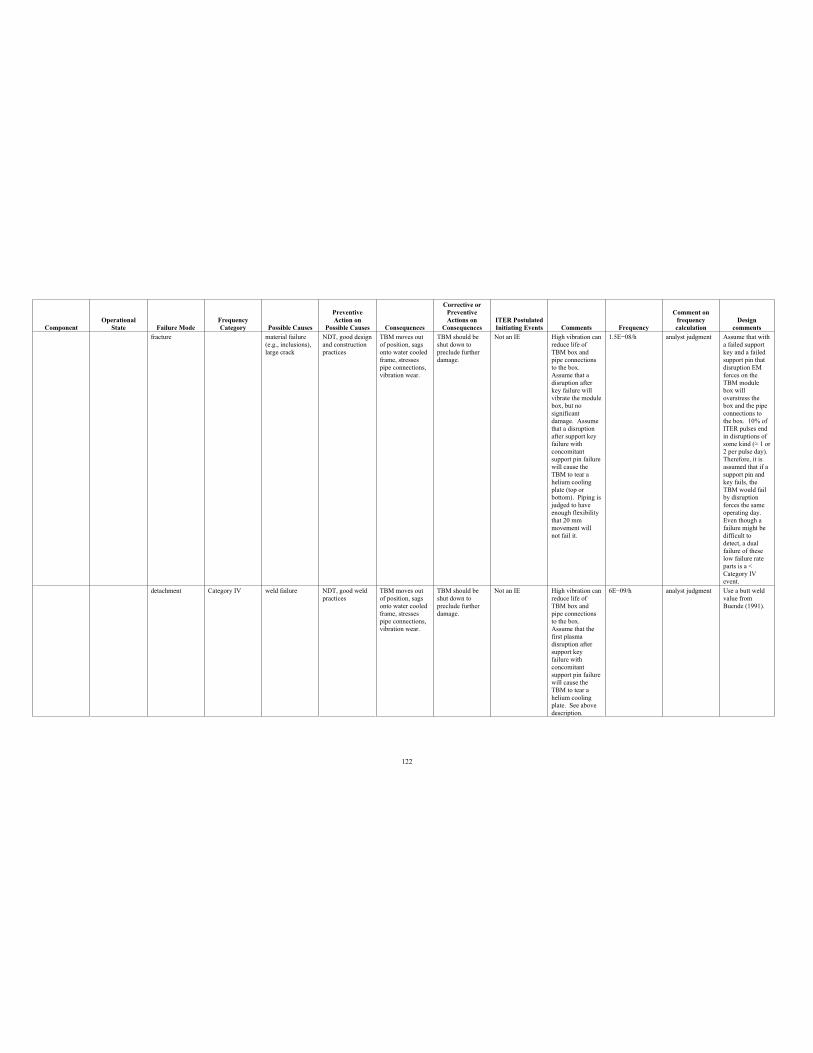
122
Component Operational
State Failure Mode Frequency Category Possible Causes
PreventiveAction on
Possible Causes Consequences
Corrective or PreventiveActions on
Consequences ITER Postulated Initiating Events Comments Frequency
Comment on frequency calculation
Design comments
fracture material failure (e.g., inclusions), large crack
NDT, good design and construction practices
TBM moves out of position, sags onto water cooled frame, stresses pipe connections, vibration wear.
TBM should be shut down to preclude further damage.
Not an IE High vibration can reduce life of TBM box and pipe connections to the box. Assume that a disruption after key failure will vibrate the module box, but no significant damage. Assume that a disruption after support key failure with concomitant support pin failure will cause the TBM to tear a helium cooling plate (top or bottom). Piping is judged to have enough flexibility that 20 mm movement will not fail it.
1.5E 08/h analyst judgment Assume that with a failed support key and a failed support pin that disruption EM forces on the TBM module box will overstress the box and the pipe connections to the box. 10% of ITER pulses end in disruptions of some kind ( 1 or 2 per pulse day). Therefore, it is assumed that if a support pin and key fails, the TBM would fail by disruption forces the same operating day. Even though a failure might be difficult to detect, a dual failure of these low failure rate parts is a < Category IV event.
detachment Category IV weld failure NDT, good weld practices
TBM moves out of position, sags onto water cooled frame, stresses pipe connections, vibration wear.
TBM should be shut down to preclude further damage.
Not an IE High vibration can reduce life of TBM box and pipe connections to the box. Assume that the first plasma disruption after support key failure with concomitant support pin failure will cause the TBM to tear a helium cooling plate. See above description.
6E 09/h analyst judgment Use a butt weld value from Buende (1991).
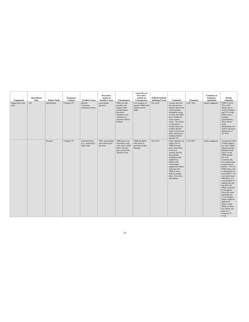
123
Component Operational
State Failure Mode Frequency Category Possible Causes
PreventiveAction on
Possible Causes Consequences
Corrective or PreventiveActions on
Consequences ITER Postulated Initiating Events Comments Frequency
Comment on frequency calculation
Design comments
Support pin, four units
NO deformation Category IV thermal overstress, mechanical stress
good design practices
TBM can slip, possibly sag against water cooling frame. Increased vibration wear, vibration on structure reduces lifetime.
Can continue to operate TBM until repairs can be made.
Not an IE Assume that one pin and one key must be failed and a daily plasma disruption occurs to cause the TBM box to strike the water cooled frame. The frame is expected to remain intact, but assume that the upper or lower top plate will breach, sending helium into the VV.
6.6E 10/h analyst judgment FMD-97 gives 78% of the failure rate as cracks (fracture) and 22% of the failure rate as bending (deformation). These failure mode distributions are used on the basic failure rate of 3E 09/h.
fracture Category IV material failure (e.g., inclusions), large crack
NDT, good design and construction practices
TBM moves out of position, sags onto water cooled frame, stresses pipe connections, vibration wear.
TBM should be shut down to preclude further damage.
Not an IE High vibration can reduce life of TBM box and pipe connections to the box. Assume that the first plasma disruption after support key failure with concomitant support pin failure will cause the TBM to tear a helium cooling plate. See above description.
2.3E 09/h analyst judgment Assume that with a failed support key and a failed support pin that disruption EM forces on the TBM module box will overstress the box and the pipe connections to the box. 10% of ITER pulses end in disruptions of some kind ( 1 or 2 per pulse day). Therefore, it is assumed that if a support pin and key fails, the TBM would fail by disruption forces the same operating day. Even though a failure might be difficult to detect, a dual failure of these low failure rate parts is a < Category IV event.
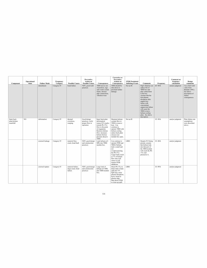
124
Component Operational
State Failure Mode Frequency Category Possible Causes
PreventiveAction on
Possible Causes Consequences
Corrective or PreventiveActions on
Consequences ITER Postulated Initiating Events Comments Frequency
Comment on frequency calculation
Design comments
detachment Category IV bond failure NDT, good weld practices
TBM moves out of position, sags onto water cooled frame, stresses pipe connections, vibration wear.
TBM should be shut down to preclude further damage.
Not an IE High vibration can reduce life of TBM box and pipe connections to the box. Assume that the first plasma disruption after support key failure with concomitant support pin failure will cause the TBM to tear a helium cooling plate. See above description.
6E 09/h analyst judgment Use a butt weld value from Buende (1991). See above description of failureconsequences.
Inner back plate/helium manifold
NO deformation Category IV thermal overstress, warping
Good design practices, verify proper flow in operation
Inner back plate deformation causes FCI cracks, retards Pb-17Li flow to the point of stagnation. Restricts helium flow, increases helium friction pressure drop in TBM.
Maintain helium coolant flow to TBM to remove heat. Can continue to operate TBM with helium cooling unless back plate stresses tear module box open.
Not an IE 1E 09/h analyst judgment Plate failure rate assumptions were described above.
external leakage Category IV material flaw, crack, bond fault
NDT, good design and construction practices
Leak helium at 8 MPa into TBM module box.
Can continue to operate ITER and TBM if helium leak is small and not overpressurizing the Pb-17Li. Larger leaks (such as 1% of helium flow rate) will cause or will require ITER shutdown.
LBB2 Despite FCI being present, assume that helium leak into that part of the TBM module will reach the Pb-17Li and pressurize it.
1E 08/h analyst judgment
external rupture Category IV material failure, large crack, bond failure
NDT, good design and construction practices
Large leak of helium at 8 MPa into TBM module box.
Drain Pb-17Li to drain tank to limit spill into VV. Spill may cause plasma disruption, heavy metal at plasma edge. Shut down ITER to clean up spill.
LBB1 1E 09/h analyst judgment
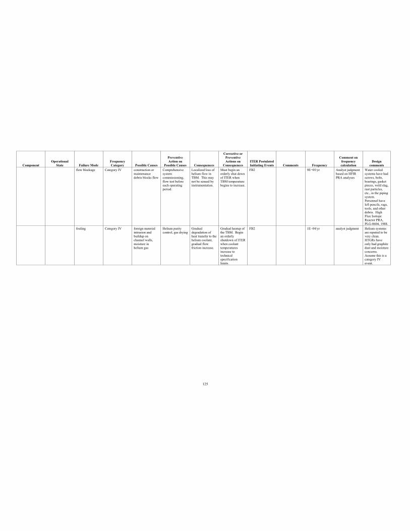
125
Component Operational
State Failure Mode Frequency Category Possible Causes
PreventiveAction on
Possible Causes Consequences
Corrective or PreventiveActions on
Consequences ITER Postulated Initiating Events Comments Frequency
Comment on frequency calculation
Design comments
flow blockage Category IV construction or maintenance debris blocks flow
Comprehensive system commissioning, flow test before each operating period.
Localized loss of helium flow in TBM. This may not be sensed by instrumentation.
Must begin an orderly shut down of ITER when TBM temperature begins to increase.
FB2 9E 05/yr Analyst judgment based on HFIR PRA analyses
Water cooled systems have had screws, bolts, bearings, gasket pieces, weld slag, rust particles, etc., in the piping system. Personnel have left pencils, rags, tools, and other debris. High Flux Isotope Reactor PRA, PLG-0604, 1988.
fouling Category IV foreign material intrusion and buildup on channel walls, moisture in helium gas
Helium purity control, gas drying
Gradual degradation of heat transfer to the helium coolant, gradual flow friction increase.
Gradual heatup of the TBM. Begin an orderly shutdown of ITER when coolant temperatures increase to technicalspecificationlimits.
FB2 1E 04/yr analyst judgment Helium systems are reputed to be very clean. HTGRs have only had graphite dust and moisture concerns. Assume this is a category IV event.
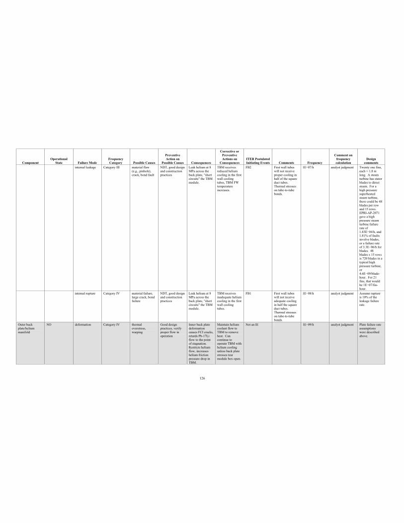
126
Component Operational
State Failure Mode Frequency Category Possible Causes
PreventiveAction on
Possible Causes Consequences
Corrective or PreventiveActions on
Consequences ITER Postulated Initiating Events Comments Frequency
Comment on frequency calculation
Design comments
internal leakage Category III material flaw (e.g., pinhole), crack, bond fault
NDT, good design and construction practices
Leak helium at 8 MPa across the back plate, "short circuits" the TBM module.
TBM receives reduced helium cooling in the first wall cooling tubes, TBM FW temperature increases.
FB2 First wall tubes will not receive proper cooling in half of the square duct tubes. Thermal stresses on tube-to-tube bonds.
1E 07/h analyst judgment Twenty one fins, each 1.8 m long. A steam turbine has stator blades to direct steam. For a high pressure superheatedsteam turbine, there could be 48 blades per row and 15 rows. EPRI-AP-2071 gave a high pressure steam turbine failure rate of 1.83E 04/h, and 1.81% of faults involve blades, or a failure rate of 3.3E 06/h for blades. 48 blades x 15 rows is 720 blades in a typical high pressure turbine, or 4.6E 09/blade-hour. For 21 fins, that would be 1E 07/fin-hour.
internal rupture Category IV material failure, large crack, bond failure
NDT, good design and construction practices
Leak helium at 8 MPa across the back plate, "short circuits" the TBM module.
TBM receives inadequate helium cooling in the first wall cooling tubes.
FB1 First wall tubes will not receive adequate cooling in half the square duct tubes. Thermal stresses on tube-to-tube bonds.
1E 08/h analyst judgment Assume rupture is 10% of the leakage failure rate.
Outer back plate/helium manifold
NO deformation Category IV thermal overstress, warping
Good design practices, verify proper flow in operation
Inner back plate deformation causes FCI cracks, retards Pb-17Li flow to the point of stagnation. Restricts helium flow, increases helium friction pressure drop in TBM.
Maintain helium coolant flow to TBM to remove heat. Can continue to operate TBM with helium cooling unless back plate stresses tear module box open.
Not an IE 1E 09/h analyst judgment Plate failure rate assumptions were described above.
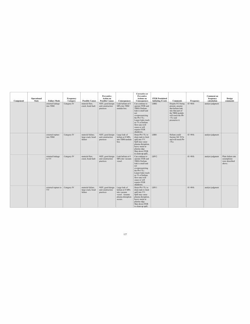
127
Component Operational
State Failure Mode Frequency Category Possible Causes
PreventiveAction on
Possible Causes Consequences
Corrective or PreventiveActions on
Consequences ITER Postulated Initiating Events Comments Frequency
Comment on frequency calculation
Design comments
external leakage into TBM
Category IV material flaw, crack, bond fault
NDT, good design and construction practices
Leak helium at 8 MPa into TBM module box.
Can continue to operate ITER and TBM if helium leak is small and not overpressurizing the Pb-17Li. Larger leaks (such as 1% of helium flow rate) will cause or will require ITER shutdown.
LBB2 Despite FCI being present, assume that helium leak into that part of the TBM module will reach the Pb-17Li and pressurize it.
1E 08/h analyst judgment
external rupture into TBM
Category IV material failure, large crack, bond failure
NDT, good design and construction practices
Large leak of helium at 8 MPa into TBM module box.
Drain Pb-17Li to drain tank to limit spill into VV. Spill may cause plasma disruption, heavy metal at plasma edge. Shut down ITER to clean up spill.
LBB1 Helium could fracture SiC FCIs and will reach Pb-17Li.
1E 09/h analyst judgment
external leakage to VV
Category IV material flaw, crack, bond fault
NDT, good design and construction practices
Leak helium at 8 MPa into vacuum vessel.
Can continue to operate ITER and TBM if helium leak is small and not overpressurizing the Pb-17Li. Larger leaks (such as 1% of helium flow rate) will cause or will require ITER shutdown.
LBV2 1E 08/h analyst judgment Plate failure rate assumptions were described above.
external rupture to VV
Category IV material failure, large crack, bond failure
NDT, good design and construction practices
Large leak of helium at 8 MPa into vacuum vessel. Assume plasma disruption occurs.
Drain Pb-17Li to drain tank to limit spill into VV. Spill may cause plasma disruption, heavy metal at plasma edge. Shut down ITER to clean up spill.
LBV1 1E 09/h analyst judgment
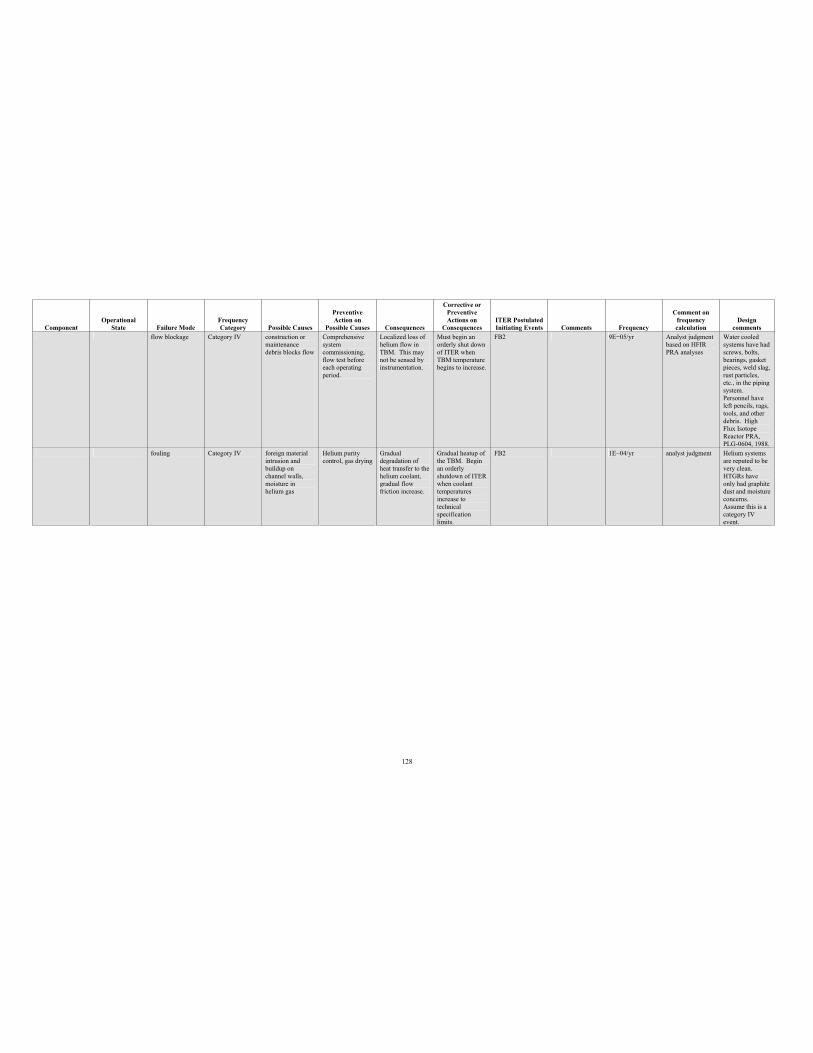
128
Component Operational
State Failure Mode Frequency Category Possible Causes
PreventiveAction on
Possible Causes Consequences
Corrective or PreventiveActions on
Consequences ITER Postulated Initiating Events Comments Frequency
Comment on frequency calculation
Design comments
flow blockage Category IV construction or maintenance debris blocks flow
Comprehensive system commissioning, flow test before each operating period.
Localized loss of helium flow in TBM. This may not be sensed by instrumentation.
Must begin an orderly shut down of ITER when TBM temperature begins to increase.
FB2 9E 05/yr Analyst judgment based on HFIR PRA analyses
Water cooled systems have had screws, bolts, bearings, gasket pieces, weld slag, rust particles, etc., in the piping system. Personnel have left pencils, rags, tools, and other debris. High Flux Isotope Reactor PRA, PLG-0604, 1988.
fouling Category IV foreign material intrusion and buildup on channel walls, moisture in helium gas
Helium purity control, gas drying
Gradual degradation of heat transfer to the helium coolant, gradual flow friction increase.
Gradual heatup of the TBM. Begin an orderly shutdown of ITER when coolant temperatures increase to technicalspecificationlimits.
FB2 1E 04/yr analyst judgment Helium systems are reputed to be very clean. HTGRs have only had graphite dust and moisture concerns. Assume this is a category IV event.
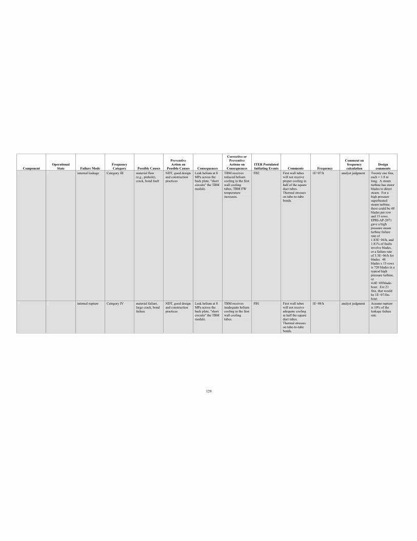
129
Component Operational
State Failure Mode Frequency Category Possible Causes
PreventiveAction on
Possible Causes Consequences
Corrective or PreventiveActions on
Consequences ITER Postulated Initiating Events Comments Frequency
Comment on frequency calculation
Design comments
internal leakage Category III material flaw (e.g., pinhole), crack, bond fault
NDT, good design and construction practices
Leak helium at 8 MPa across the back plate, "short circuits" the TBM module.
TBM receives reduced helium cooling in the first wall cooling tubes, TBM FW temperature increases.
FB2 First wall tubes will not receive proper cooling in half of the square duct tubes. Thermal stresses on tube-to-tube bonds.
1E 07/h analyst judgment Twenty one fins, each 1.8 m long. A steam turbine has stator blades to direct steam. For a high pressure superheatedsteam turbine, there could be 48 blades per row and 15 rows. EPRI-AP-2071 gave a high pressure steam turbine failure rate of 1.83E 04/h, and 1.81% of faults involve blades, or a failure rate of 3.3E 06/h for blades. 48 blades x 15 rows is 720 blades in a typical high pressure turbine, or 4.6E 09/blade-hour. For 21 fins, that would be 1E 07/fin-hour.
internal rupture Category IV material failure, large crack, bond failure
NDT, good design and construction practices
Leak helium at 8 MPa across the back plate, "short circuits" the TBM module.
TBM receives inadequate helium cooling in the first wall cooling tubes.
FB1 First wall tubes will not receive adequate cooling in half the square duct tubes. Thermal stresses on tube-to-tube bonds.
1E 08/h analyst judgment Assume rupture is 10% of the leakage failure rate.
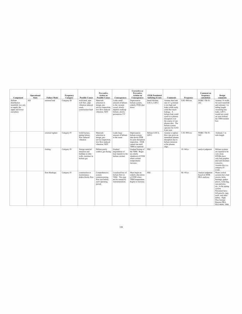
130
Component Operational
State Failure Mode Frequency Category Possible Causes
PreventiveAction on
Possible Causes Consequences
Corrective or PreventiveActions on
Consequences ITER Postulated Initiating Events Comments Frequency
Comment on frequency calculation
Design comments
Helium distribution manifold, two sets to supply the upper and lower end plates
NO external leak Category III weld fault, pipe wall flaw, pipe vibration induced crack,construction fault
Materials selection in design, pre-service inspection, low flow-induced vibration, NDT
Leaks small amount of helium to the vacuum vessel, slowly depletes makeup helium, slowly pressurizes VV
Depressurize helium system, orderly ITER shut down
Small Helium LOCA, LBV2
Assume that leak rate of 1 g/minute is too high and leaks could easily yield that much leakage. A helium leak could result in a plasma disruption over the course of one plasma shot. The helium system operates for 4,032 h per year.
9.8E 08/h-m WSRC-TR-93-262
Assume 18 welds for each manifold and estimate 1 m tubing length. Assuming tiny leaks, LBV3, would not create an issue behind the TBM module box.
external rupture Category IV weld fracture, piping failure, flow induced vibration
Materials selection in design, pre-service inspection, low flow-induced vibration, NDT
Leaks large amount of helium to the room
Depressurize helium system, shut down ITER for post-disruption inspection. ITER cannot run until TBM is repaired.
Helium LOCA, LBV1
Assume a rupture flow rate gives an immediate plasma disruption due to helium intrusion at the plasma edge.
3.3E 09/h-m WSRC-TR-93-262
Estimate 1 m tube length
fouling Category IV foreign material intrusion and buildup on tube walls, moisture in helium gas
Helium purity control, gas drying
Gradual degradation of heat transfer to the helium coolant
Gradual heatup of the TBM. Begin an orderly shutdown of ITER when coolant temperatures increase.
FB2 1E 04/yr analyst judgment Helium systems are reputed to be very clean. HTGRs have only had graphite dust and moisture concerns. Assume this is a category IV event.
flow blockage Category IV construction or maintenance debris blocks flow
Comprehensive system commissioning, flow test before each operating period.
Localized loss of helium flow in TBM. This may not be sensed by instrumentation.
Must begin an orderly shut down of ITER when TBM temperature begins to increase.
FB2 9E 05/yr Analyst judgment based on HFIR PRA analyses
Water cooled systems have had screws, bolts, bearings, gasket pieces, weld slag, rust particles, etc., in the piping system. Personnel have left pencils, rags, tools, and other debris. High Flux Isotope Reactor PRA, PLG-0604, 1988.
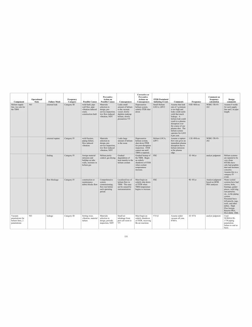
131
Component Operational
State Failure Mode Frequency Category Possible Causes
PreventiveAction on
Possible Causes Consequences
Corrective or PreventiveActions on
Consequences ITER Postulated Initiating Events Comments Frequency
Comment on frequency calculation
Design comments
Helium supply line, two sets for the TBM
NO external leak Category III weld fault, pipe wall flaw, pipe vibration induced crack,construction fault
Materials selection in design, pre-service inspection, low flow-induced vibration, NDT
Leaks small amount of helium to the vacuum vessel, slowly depletes makeup helium, slowly pressurizes VV
Depressurize helium system, orderly ITER shut down
Small Helium LOCA, LBV2
Assume that leak rate of 1 g/minute is too high and leaks could easily yield that much leakage. A helium leak could result in a plasma disruption over the course of one plasma shot. The helium system operates for 4,032 h per year.
9.8E 08/h-m WSRC-TR-93-262
Assume 8 welds for each supply line and 2 m pipe length.
external rupture Category IV weld fracture, piping failure, flow induced vibration
Materials selection in design, pre-service inspection, low flow-induced vibration, NDT
Leaks large amount of helium to the room
Depressurize helium system, shut down ITER for post-disruption inspection. ITER cannot run until TBM is repaired.
Helium LOCA, LBV1
Assume a rupture flow rate gives an immediate plasma disruption due to helium intrusion at the plasma edge.
3.3E 09/h-m WSRC-TR-93-262
fouling Category IV foreign material intrusion and buildup on tube walls, moisture in helium gas
Helium purity control, gas drying
Gradual degradation of heat transfer to the helium coolant
Gradual heatup of the TBM. Begin an orderly shutdown of ITER when coolant temperatures increase.
FB2 1E 04/yr analyst judgment Helium systems are reputed to be very clean. HTGRs have only had graphite dust and moisture concerns. Assume this is a category IV event.
flow blockage Category IV construction or maintenance debris blocks flow
Comprehensive system commissioning, flow test before each operating period.
Localized loss of helium flow in TBM. This may not be sensed by instrumentation.
Must begin an orderly shut down of ITER when TBM temperature begins to increase.
FB2 9E 05/yr Analyst judgment based on HFIR PRA analyses
Water cooled systems have had screws, bolts, bearings, gasket pieces, weld slag, rust particles, etc., in the piping system. Personnel have left pencils, rags, tools, and other debris. High Flux Isotope Reactor PRA, PLG-0604, 1988.
Vacuum penetrations for helium lines, 2 penetrations
NO leakage Category III fretting wear, vibration, material failure
Materials selection in design, periodic inspection, NDT
Small air inleakage from port cell room to VV
Must begin an orderly shutdown of ITER, receiving Be-air reactions
VVA2 Assume under vacuum all year, 8760 h.
1E 07/h analyst judgment Used NUREG/CR-1730 piping penetration failure to seal as basis.
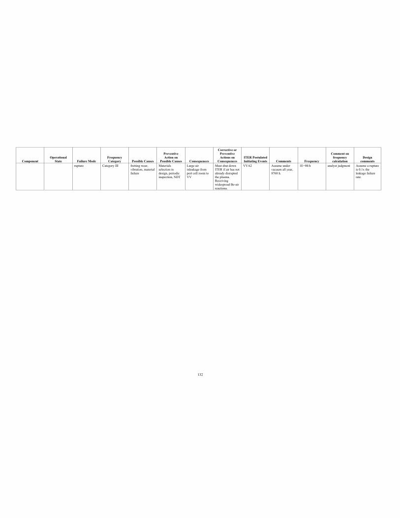
132
Component Operational
State Failure Mode Frequency Category Possible Causes
PreventiveAction on
Possible Causes Consequences
Corrective or PreventiveActions on
Consequences ITER Postulated Initiating Events Comments Frequency
Comment on frequency calculation
Design comments
rupture Category III fretting wear, vibration, material failure
Materials selection in design, periodic inspection, NDT
Large air inleakage from port cell room to VV
Must shut down ITER if air has not already disrupted the plasma. Receivingwidespread Be-air reactions.
VVA2 Assume under vacuum all year, 8760 h.
1E 08/h analyst judgment Assume a rupture is 0.1x the leakage failure rate.
133
Appendix D
Active Repair Times for TBM Pb-17Li Components
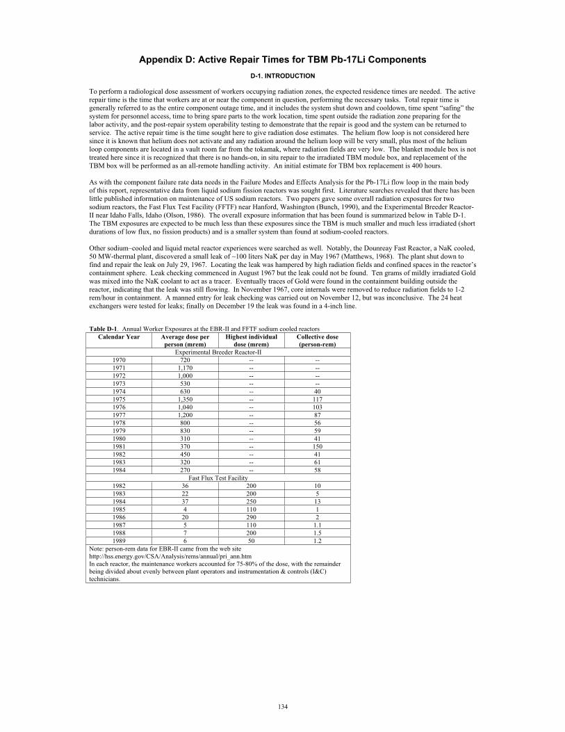
134
Appendix D: Active Repair Times for TBM Pb-17Li Components D-1. INTRODUCTION
To perform a radiological dose assessment of workers occupying radiation zones, the expected residence times are needed. The active repair time is the time that workers are at or near the component in question, performing the necessary tasks. Total repair time is generally referred to as the entire component outage time, and it includes the system shut down and cooldown, time spent “safing” the system for personnel access, time to bring spare parts to the work location, time spent outside the radiation zone preparing for the labor activity, and the post-repair system operability testing to demonstrate that the repair is good and the system can be returned to service. The active repair time is the time sought here to give radiation dose estimates. The helium flow loop is not considered here since it is known that helium does not activate and any radiation around the helium loop will be very small, plus most of the helium loop components are located in a vault room far from the tokamak, where radiation fields are very low. The blanket module box is not treated here since it is recognized that there is no hands-on, in situ repair to the irradiated TBM module box, and replacement of the TBM box will be performed as an all-remote handling activity. An initial estimate for TBM box replacement is 400 hours.
As with the component failure rate data needs in the Failure Modes and Effects Analysis for the Pb-17Li flow loop in the main bodyof this report, representative data from liquid sodium fission reactors was sought first. Literature searches revealed that there has been little published information on maintenance of US sodium reactors. Two papers gave some overall radiation exposures for two sodium reactors, the Fast Flux Test Facility (FFTF) near Hanford, Washington (Bunch, 1990), and the Experimental Breeder Reactor-II near Idaho Falls, Idaho (Olson, 1986). The overall exposure information that has been found is summarized below in Table D-1.The TBM exposures are expected to be much less than these exposures since the TBM is much smaller and much less irradiated (shortdurations of low flux, no fission products) and is a smaller system than found at sodium-cooled reactors.
Other sodium–cooled and liquid metal reactor experiences were searched as well. Notably, the Dounreay Fast Reactor, a NaK cooled,50 MW-thermal plant, discovered a small leak of ~100 liters NaK per day in May 1967 (Matthews, 1968). The plant shut down to find and repair the leak on July 29, 1967. Locating the leak was hampered by high radiation fields and confined spaces in the reactor’s containment sphere. Leak checking commenced in August 1967 but the leak could not be found. Ten grams of mildly irradiated Goldwas mixed into the NaK coolant to act as a tracer. Eventually traces of Gold were found in the containment building outside thereactor, indicating that the leak was still flowing. In November 1967, core internals were removed to reduce radiation fields to 1-2 rem/hour in containment. A manned entry for leak checking was carried out on November 12, but was inconclusive. The 24 heat exchangers were tested for leaks; finally on December 19 the leak was found in a 4-inch line.
Table D-1. Annual Worker Exposures at the EBR-II and FFTF sodium cooled reactors Calendar Year Average dose per
person (mrem) Highest individual
dose (mrem) Collective dose (person-rem)
Experimental Breeder Reactor-II 1970 720 -- -- 1971 1,170 -- -- 1972 1,000 -- -- 1973 530 -- -- 1974 630 -- 40 1975 1,350 -- 117 1976 1,040 -- 103 1977 1,200 -- 87 1978 800 -- 56 1979 830 -- 59 1980 310 -- 41 1981 370 -- 150 1982 450 -- 41 1983 320 -- 61 1984 270 -- 58
Fast Flux Test Facility 1982 36 200 10 1983 22 200 5 1984 37 250 13 1985 4 110 1 1986 20 290 2 1987 5 110 1.1 1988 7 200 1.5 1989 6 50 1.2
Note: person-rem data for EBR-II came from the web site http://hss.energy.gov/CSA/Analysis/rems/annual/pri_ann.htm In each reactor, the maintenance workers accounted for 75-80% of the dose, with the remainder being divided about evenly between plant operators and instrumentation & controls (I&C) technicians.
135
The line was drained, cut with hacksaws, and removed. In the January-February time frame, scaffolds were erected, pipe lagging was removed, new pipework was designed and fabricated, equipment was tested, and an internal pipe welding machine was developed. Detailed work plans were made to reduce exposure time. Repairs proceeded in March 1968. The work went slowly due to each person’s exposure limit of 1 rem/month; this dose limit could be realized in as little as 2 hours of labor. Several staff volunteered to receive an allowable overexposure of 10 rem/month. In welding, NaK would melt and contaminate the weld, so sodium metal plugs were fashioned and pushed ~18 cm into the pipe ends to confine the NaK away from the weld heat affected zones. Eventually the pipewas welded into place and radiographed, then pressure tested (leaving the plugs inside the pipe ends). The Dounreay plant restartedon June 22, 1968. This was roughly eleven months of outage time for a 100 liter/day leak.
The Phenix sodium-cooled plant had cracks forming in some of the superheater and reheater tubes (Cavagna, 2006). In 2001 a building was constructed to handle the tubes for weld repair. Over nine months in 2002, forty-seven steam generator superheater/reheater modules (7 tubes per module) measuring 16.9 m long were removed, given > 160 hours of cleaning, and then were welded and radiographed. 1,500 welds were made and inspected using 8,500 gamma radiographs. Personnel exposure totalled 6.1 mSv for the task. In two additional months in 2002, all of the modules were reassembled in the Phenix steam generator.Assuming that just one of these modules is comparable to a TBM heat exchanger, then 11 months or 334 days/47 modules gives roughly 7 days per module. This is a poor average, since the time to uninstall and reinstall the tube module is distributed over all of the modules, but it does give the order of magnitude of a tube repair activity.
This document treats three types of repair times, the active repair for corrective maintenance (e.g., replacing a seal on an existingcomponent), the active maintenance time to perform routine actions (e.g., calibration, inspection, surveillance testing), and the active repair time to replace a component (e.g., replace a pump, tank or valve). Some component repair times for water system componentsin nuclear and in typical industrial environments have been assembled to apply to the Pb-17Li flow loop. Unfortunately, statisticaltabulations of repair time data are sparse in the literature. The best known sources of averaged labor times are for construction labor estimating (Means, 2007) and for automobile mechanical repair (Chilton, 2007). Without fusion or fission liquid metal maintenancetime data readily available, water cooling system data are used here. The water system data mainly come from power generation, both fossil and nuclear, and other commercial industries. The TBM is much smaller than the components maintained in the power generation industry, so effort was made to find repair times applicable to small size components. For example, Milivojevic (1989)gave repair times for PWR primary cooling pumps that ranged from 142.9 hours to 500 hours in the first 10,000 hours of operation.The repair time peaked at 2,000 hours and was as low as 100 hours over pump lifetime. The overall Mean Time To Repair (MTTR) was ~1,000 hours. However, a PWR primary coolant pump is large (7.5 MW, versus 20 kW for the TBM, and water flows of ~350 Mg/minute versus Pb-17Li flow at 72 kg/minute) and requires different maintenance demands (scaffolds, cranes, etc.) to service theunit. Comparing Milivojevic data on a set of about 500 PWR pumps to collected data on smaller water pump units shows that for smaller centrifugal pumps, the mean time to repair (MTTR) is much smaller: 6.8 hours (pumps flowing less than 3.6 Mg/minute), 7.8hours (pumps with flow rates between 3.6 and 7.3 Mg/minute), and 26.7 hours (pumps with flow rates between 7.3 and 364 Mg/minute) (Shultz, 982; Cullinane, 1989). Another important source of repair times has been given by Butler (2000) for repairs to shipboard components – these components are much closer to the TBM in size than the large power plant components. When repair times for small size components were not available, the repair times for large-scale components were ratioed down to apply to theTBM. The US TBM is helium and lithium-lead cooled rather than water-cooled, but the power industry data for water system components are the most representative repair times available to apply to the low pressure lithium-lead components of interest, and are presently the most reasonable data to use for the scoping ORE assessment. It is noted from the literature that past fusion OREestimates have also used fission reactor experiences to give repair times (Sandri, 2000; Sandri, 2002; Sandri, 2004). Efforts are also being made to collect actual operating experiences from existing tokamaks to support ITER ORE estimates (Natalizio, 2005; Natalizio, 2005a); however, these data are of limited use on the TBM since the TBM is a unique piece of equipment that is not presently used in tokamaks.
D-2. ACTIVE REPAIR TIMES
The main Pb-17Li flow loop components, their failure rates and failure probabilities per year (taken from the TBM preliminary FMEAtables in Appendix A), and the average active repair times; that is, mean time to repair (MTTR) values, are listed in Table D-2.
It is noted in Table 2 that most of the annual probabilities of needing repairs to any given component in a particular component type are small. Therefore, in a given year there may not be any repair activities. However, there will be annual preventive maintenance,surveillance testing, and inspections of the flow loop components. Lofaro (1991) discussed frequencies of testing light water reactor Component Cooling Water System components. MOV stroke time and valve seat leakage, and check valve leakage and flow, were measured each 3 months. Pressure relief valve setpoints were checked each 5 years. Pump vibration and pump head were tested each3 months, as well as suction pressure, flow rate, bearing temperature, lubricant temperature and level, motor voltage, and performance testing. Pump inspection and maintenance for water system pumps has been discussed by Karassik (1976). Karassik suggested dailyinspections (just a few minutes duration) to listen for suspect noises and look for leakage of either process fluid or bearing lube oil.Semi-annual inspections for seal performance and bearing lubricant change were recommended, and annual bearing and shaft packinginspection should be performed. Therefore, it seems that many tests and inspections are carried out several times per year and the entries into radiation areas for these purposes will give higher annual exposure times for personnel than the repair activities.
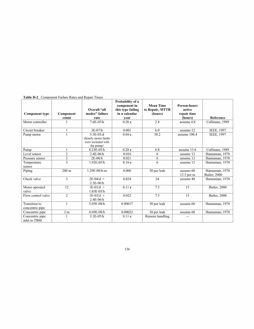
136
Table D-2. Component Failure Rates and Repair Times
Component type Componentcount
Overall “all modes” failure
rate
Probability of a component in
this type failing in a calendar
year
Mean Time to Repair, MTTR
(hours)
Person-hours active
repair time(hours) Reference
Motor controller 1 7.6E-05/h 0.26 c 2.4 assume 4.8 Cullinane, 1989
Circuit breaker 1 3E-07/h 0.001 6.0 assume 12 IEEE, 1997 Pump motor 1 5.5E-03/d
(hourly motor faults were included with
the pump)
0.04 c 50.2 assume 100.4 IEEE, 1997
Pump 1 8.23E-05/h 0.28 c 6.8 assume 13.6 Cullinane, 1989 Level sensor 2 2.4E-06/h 0.016 6 assume 12 Hannaman, 1978 Pressure sensor 3 2E-06/h 0.021 6 assume 12 Hannaman, 1978 Temperature sensor
3 1.92E-05/h 0.18 c 6 assume 12 Hannaman, 1978
Piping 200 m 1.29E-08/h-m 0.006 30 per leak assume 60 12.5 per m
Hannaman, 1978 Butler, 2000
Check valve 3 2E-04/d + 2.5E-06/h
0.024 24 assume 48 Hannaman, 1978
Motor operated valve
12 1E-03/d + 1.65E-05/h
0.11 c 7.5 15 Butler, 2000
Flow control valve 2 1E-03/d + 2.4E-06/h
0.022 7.5 15 Butler, 2000
Transition to concentric pipe
1 5.05E-08/h 0.00017 30 per leak assume 60 Hannaman, 1978
Concentric pipe 2 m 6.69E-08/h 0.00022 30 per leak assume 60 Hannaman, 1978 Concentric pipe inlet to TBM
1 3.3E-05/h 0.11 c Remote handling --
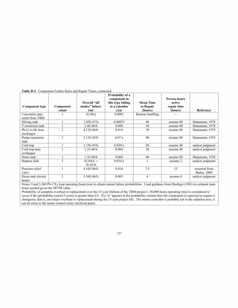
137
Table D-2. Component Failure Rates and Repair Times, continued.
Component type Componentcount
Overall “all modes” failure
rate
Probability of a component in
this type failing in a calendar
year
Mean Time to Repair(hours)
Person-hours active
repair time(hours) Reference
Concentric pipe outlet from TBM
1 1E-04/y 0.0001 Remote handling --
Mixing tank 1 1.05E-07/h 0.00035 40 assume 80 Hannaman, 1978 T extraction tank 1 2.4E-06/h 0.008 30 assume 60 Hannaman, 1978 Pb-Li to He heat exchanger
1 4.11E-06/h 0.014 30 assume 60 Hannaman, 1978
Pump expansion tank
1 2.11E-05/h 0.07 c 40 assume 80 Hannaman, 1978
Cold trap 1 1.15E-05/h 0.039 c 20 assume 40 analyst judgment Cold trap heat exchanger
1 1.1E-06/h 0.004 20 assume 40 analyst judgment
Drain tank 1 1.1E-06/h 0.004 40 assume 80 Hannaman, 1978 Rupture disk 1 1E-04/d +
1E-05/h0.034 c 1 assume 2 analyst judgment
Pressure relief valve
1 4.16E-06/h 0.014 7.5 15 assumed from Butler, 2000
Drain tank electric heater
1 1.56E-06/h 0.005 4 assume 8 analyst judgment
Notes: Used 3,360 Pb-17Li loop operating hours/year to obtain annual failure probabilities. Used guidance from Derdiger (1981) to estimate man-hours needed given the MTTR value. Probability of complete overhaul or replacement over the 15-year lifetime of the TBM project (~50,000 hours operating time) is considered to occur if the (probability/year)(15 years) is greater than 0.5. If a “c” appears in the probability column then the component is expected to require a changeout; that is, one major overhaul or replacement during the 15-year project life. The motor controller is probably not in the radiation area, it can be close to the motor control center electrical panel.
138
D-3. COMPONENT TESTING, PREVENTIVE MAINTENANCE AND CALIBRATION TIMES
The largest yearly reason to enter the TBM port cell is for component inspection, surveillance testing, preventive maintenance, and calibration. Typical times for these activities in the fission industry are given in Table D-3. At present, it is not clear if fission-type inspections will be necessary on a yearly basis if the Pb-17Li piping is removed to replace the TBM module box every other year. The box removal will allow detailed inspection of the flow loop components on a biannual basis. Some explanations of the fission-based inspection times are given below.
An issue of importance is weld and piping tests. It is assumed that TBM welds in piping would be radiographed during construction, then the inspections would switch to ultrasonic (volumetric) inspection and dye penetration testing performed annually. At the Advanced Test Reactor (ATR), a fission reactor for materials irradiation at the INL, weld inspection is performed in two parts. The first part is dye penetrant. The technician wipes the pipe surface clean with dry rags, or a cleanser if necessary, then paints red dye on the weld with a brush or spray can, lets the dye penetrate for about 10 minutes, the wipes down excess dye with another rag. Then a cleaner solution or plain water is used to remove residual surface dye and the weld is wiped down with rags again. After the solution or water is dried, a developer solution is sprayed on the pipe. The technician waits for 7-8 minutes and visually inspects for indications of dye in any cracks. If none are found, the white residue from the developer is wiped off to prepare the pipe weld for ultrasonic inspection. The dye process typically takes about 30 minutes for a 10 cm-diameter pipe. The technician, who usually works alone but has a buddy standing by outside the radiological area, can retreat from the radiation area during drying times, so exposure is only about 10 minutes out of the 30-minute process.
The second part of weld inspection is ultrasonic testing (UT). UT is performed by hand and requires less than 10 minutes per weld to access the weld in a 5 cm-diameter pipe, start the UT equipment, apply the petroleum jelly on the weld for good contact with the probe, track the probe around the weld circumference, verify that the inspection data was good, wipe the jelly off the pipe, and leave the weld location. For a 10 cm-diameter pipe, the ultrasonic test time would be 10-15 minutes/weld. Small piping under 5 cm-diameter would take perhaps only 5-10 minutes per weld. For small diameter welds, the total technician exposure time is estimated to be 20 minutes per weld during a combined dye and UT inspection.
Assuming a total of 200 m of piping in the TBM Pb-17Li flow loop, and assuming that a pipe section is typically 3 m, and has on average 1 weld, gives 67 welds to inspect in the loop. Assuming the 20% inspection per year to give complete flow loop inspection in 5 years of loop lifetime gives 13 welds to inspect per year. At 20 minutes inspection time within the radiation field per weld, this is 4.3 hours per year for the piping welds.
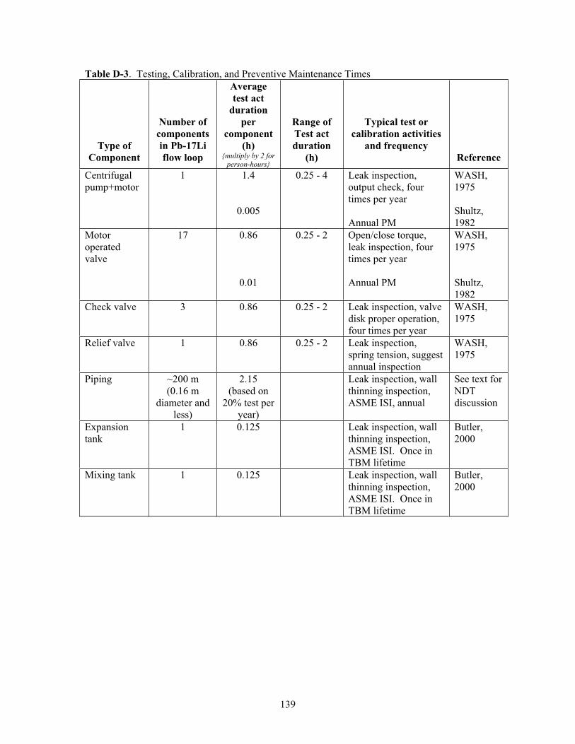
139
Table D-3. Testing, Calibration, and Preventive Maintenance Times
Type of Component
Number of componentsin Pb-17Li flow loop
Averagetest act
durationper
component(h)
{multiply by 2 for person-hours}
Range of Test act duration
(h)
Typical test or calibration activities
and frequency Reference
Centrifugalpump+motor
1 1.4
0.005
0.25 - 4 Leak inspection, output check, four times per year
Annual PM
WASH,1975
Shultz,1982
Motoroperatedvalve
17 0.86
0.01
0.25 - 2 Open/close torque, leak inspection, four times per year
Annual PM
WASH,1975
Shultz,1982
Check valve 3 0.86 0.25 - 2 Leak inspection, valve disk proper operation, four times per year
WASH,1975
Relief valve 1 0.86 0.25 - 2 Leak inspection, spring tension, suggest annual inspection
WASH,1975
Piping ~200 m (0.16 m
diameter and less)
2.15(based on
20% test per year)
Leak inspection, wall thinning inspection, ASME ISI, annual
See text for NDTdiscussion
Expansiontank
1 0.125 Leak inspection, wall thinning inspection, ASME ISI. Once in TBM lifetime
Butler,2000
Mixing tank 1 0.125 Leak inspection, wall thinning inspection, ASME ISI. Once in TBM lifetime
Butler,2000
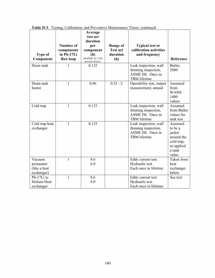
140
Table D-3. Testing, Calibration, and Preventive Maintenance Times, continued.
Type of Component
Number of componentsin Pb-17Li flow loop
Averagetest act
durationper
component(h)
{multiply by 2 for person-hours}
Range of Test act duration
(h)
Typical test or calibration activities
and frequency Reference
Drain tank 1 0.125 Leak inspection, wall thinning inspection, ASME ISI. Once in TBM lifetime
Butler,2000
Drain tank heater
1 0.86 0.25 - 2 Operability test, output measurement, annual
Assumed from WASH-1400 values
Cold trap 1 0.125 Leak inspection, wall thinning inspection, ASME ISI. Once in TBM lifetime
Assumed from Butler values for tank test
Cold trap heat exchanger
1 0.125 Leak inspection, wall thinning inspection, ASME ISI. Once in TBM lifetime
Assumed to be a jacketaround the cold trap, so applied a tank value.
Vacuum permeator (like a heat exchanger)
1 8.6 6.0
Eddy current test. Hydraulic test. Each once in lifetime
Taken from heatexchangerbelow
Pb-17Li to Helium Heat exchanger
1 8.6 6.0
Eddy current test. Hydraulic test. Each once in lifetime
See text
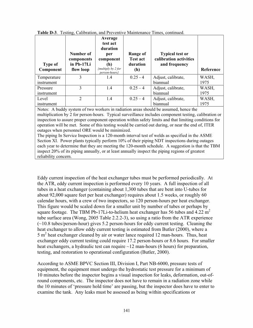
141
Table D-3. Testing, Calibration, and Preventive Maintenance Times, continued.
Type of Component
Number of componentsin Pb-17Li flow loop
Averagetest act
durationper
component(h)
{multiply by 2 for person-hours}
Range of Test act duration
(h)
Typical test or calibration activities
and frequency Reference
Temperature instrument
3 1.4 0.25 - 4 Adjust, calibrate, biannual
WASH,1975
Pressureinstrument
3 1.4 0.25 – 4 Adjust, calibrate, biannual
WASH,1975
Levelinstrument
2 1.4 0.25 – 4 Adjust, calibrate, biannual
WASH,1975
Notes: A buddy system of two workers in radiation areas should be assumed, hence the multiplication by 2 for person-hours. Typical surveillance includes component testing, calibration or inspection to assure proper component operation within safety limits and that limiting conditions for operation will be met. Some of this testing would be carried out during, or near the end of, ITER outages when personnel ORE would be minimized. The piping In Service Inspection is a 120-month interval test of welds as specified in the ASME Section XI. Power plants typically perform 10% of their piping NDT inspections during outages each year to determine that they are meeting the 120-month schedule. A suggestion is that the TBM inspect 20% of its piping annually, or at least annually inspect the piping regions of greatest reliability concern.
Eddy current inspection of the heat exchanger tubes must be performed periodically. At the ATR, eddy current inspection is performed every 10 years. A full inspection of all tubes in a heat exchanger (containing about 1,300 tubes that are bent into U-tubes for about 92,000 square feet per heat exchanger) requires about 1.5 weeks, or roughly 60 calendar hours, with a crew of two inspectors, so 120 person-hours per heat exchanger.This figure would be scaled down for a smaller unit by number of tubes or perhaps by square footage. The TBM Pb-17Li-to-helium heat exchanger has 56 tubes and 4.22 m2
tube surface area (Wong, 2005 Table 2.2.2-3), so using a ratio from the ATR experience (~10.8 tubes/person-hour) gives 5.2 person-hours for eddy current testing. Cleaning the heat exchanger to allow eddy current testing is estimated from Butler (2000), where a 5 m2 heat exchanger cleaned by air or water lance required 12 man-hours. Thus, heat exchanger eddy current testing could require 17.2 person-hours or 8.6 hours. For smaller heat exchangers, a hydraulic test can require ~12 man-hours (6 hours) for preparation, testing, and restoration to operational configuration (Butler, 2000).
According to ASME BPVC Section III, Division I, Part NB-6000, pressure tests of equipment, the equipment must undergo the hydrostatic test pressure for a minimum of 10 minutes before the inspector begins a visual inspection for leaks, deformation, out-of-round components, etc. The inspector does not have to remain in a radiation zone while the 10 minutes of ‘pressure hold time’ are passing, but the inspector does have to enter to examine the tank. Any leaks must be assessed as being within specifications or
142
originating from temporary seals installed to perform the test. Considering the test setup time, gradual pressure increase time, hold time, inspection time, and pressure bleed-off time, a rough estimate of 1 hour is needed for pressure tests, but the Inspector and one system engineer do not stay in the radiation zone the entire time. A pressure test is performed before initial operation and after each major refurbishment of the system.
Some instruments can be calibrated remotely, and this capability is worth investigation for the TBMs (Hashemian, 1993). These so-called smart sensors are digital units that can accept remote commands; self-interrogate, self-adjust and even self-calibrate. If these sensors work well in the ITER fringe magnetic field, they would be useful to reduce personnel radiation exposure and also reduce personnel exposure to industrial hazards in the port cell.
D-4 COMPONENT REPLACEMENT TIMES
The third aspect of repairs is replacement of components. Replacement would only occur as a result of a complete failure that is too extensive to repair locally (e.g., pump impeller binds on pump volute) or too time consuming in a radiation field to repair (e.g., motor winding replacement), or externally-induced damage to a component. Some equipment replacement times from the Advanced Test Reactor (ATR), a fission reactor for materials irradiation at the INL, have been gathered to give some insights on component replacement times.
Major overhauls of equipment, or equipment replacements, tend to be lengthy but rare events, perhaps occurring every 5 to 10 years. Some data on typical repairs and major equipment overhaul times have been taken from INL internal records on the Advanced Test Reactor (ATR; operated 1968-present). ATR is a 250 MW-thermal fission reactor for materials irradiation. Several events are discussed below.
On October 10, 1992, a small heat exchanger at ATR suffered a tube failure that resulted in tube-side liquid flowing into shell-side liquid. The heat exchanger had only been in service for 8 years. Operators noted what appeared to be a 17 gallon/minute leak from the process fluid to the lower pressure cooling fluid. For this heat exchanger unit neither the process fluid (tube side at 200 psi) nor the cooling fluid (shell side) were radioactive, but the fluid was important to proper operation of the plant. The reactor was shut down and the affected heat exchanger (one of two side-by-side units) was identified. The heat exchanger was shut down and cooled down, then the stuffing box was accessed. The leaking stainless steel tube was located, plugged, and the three adjacent tubes were also plugged in case the damaged tube had inflicted damage on the neighboring tubes. The tube bundle was not pulled to inspect the failure, that action was deferred to a later time in favor of plant restart. The heat exchanger was scheduled to be inspected during a future scheduled outage. The heat exchanger was pressure tested on both tube and shell sides and upon satisfactory results it was returned to service. Vibration and acoustical monitoring were also installed to allow for increased surveillance in case another tube failed. From plant scram to power ascension, 166 hours of operating time were lost. Accounting for overall plant cooldown, then heatup & power ascension time, that leaves approximately 150 calendar hours for the tube repair activity. The number of workers is
143
not known. It is assumed that there was one mechanic, one testing technician for tube eddy current testing, a radiological controls technician, and one foreman/supervisor. Some other typical repairs have included a 3-inch pipe weld repair on October 24, 1992 – the small pipe leak was sensed, the pipe was depressurized and cooled for personnel safety. Repair time took 80 calendar hours to cut out the old pipe section, check the pipe ends, weld in a new pipe piece, and radiograph the work. On February 12, 1995, a very small water pump began to leak at its volute seal, the gasket was “washing out”.Replacement of the seal required 92 calendar hours of reactor forced outage for repair and pressure test of the pump to return it to service, so 76 hours of actual repair time. On December 8, 1998, a one-inch pipe tee began to leak about 1 gallon/hour. From plant scram to power ascension, 120 hours of operating time were lost. Repair of the leaking weld required ~104 calendar hours for access, re-welding, radiography, and pressure test. The number of personnel is not known, but the area is a contamination zone, so as a guess, two welders, a radiation worker for decon, preparation, and area cleanup work, and a health physics technician. The supervisor and fire watch could observe from outside the zone.
Large equipment overhauls at ATR have included the four, 36-inch diameter check valves in the primary coolant system. During a plant outage, these valves were disassembled, decontaminated, inspected, the valve disk pins were surface re-hardened, the dash pot assemblies were cleaned and inspected for corrosion, the valve case was non-destructive test (NDT) inspected, then the valves were reassembled and the casing bolts torqued. The valves were leak checked and functionally tested, then declared operable again. The four valves were isolated at 0243 hours on September 25, 1995, then drained. Once dry, they were disassembled and parts laid down on the floor near the valves. Decontamination was performed, then interior inspection. Clevis units and hinge pins were hard surfaced. The valve case seals were changed and the valves reassembled. The valve bolts were retorqued and the valves were re-flooded for leak testing. This was accomplished for all four valves by 2352 hours on October 3, 1995, for a total of about 213 calendar hours. Thus, the overhaul of one large check valve would have required about 53.5 calendar hours with a crew of four workers (mechanics, fitters, and health physics technicians for survey and decon tasks).
A small, 40 hp electric-motor driven centrifugal pump, 4,700 gpm water flow, at the ATR required shaft seal changeout. The pump shaft is horizontal. During a planned reactor outage on February 9, 1997, the pump was shut down and isolated at 2010 hours. At 1800 hours on February 10 the work began. The mechanic removed the pump top case and wrapped it in plastic to contain contamination left behind from evaporated coolant water. Radiological smear samples in the dry pump casing read 50 mr/h, so work was suspended until a new Radiation Work Permit and ALARA review could be completed. Work stopped at 2249 hours while awaiting new paperwork. Work resumed at 1400 hours on February 13, the new seals were placed and the pump case top rebolting began by 1730 hours. Rebolting the pump casing top was completed and a pressure test took place at 2225 hours. The test failed; another set of new seals were needed. On February 17, from 1455 to 2310 hours, seal replacement tasks were under way. On February 18, work continued between 1120 and 1630 hours, ending with a leak check that showed a 1
144
pint/minute leak (too high of a leak rate). Another two hours of labor were needed to correct the new seal leak problem. The total time was 4.75+8.5+8+5+2 for two seal installations, or ~14 hours per seal for two mechanics. The companion pump unit seal replacement began at 0800 on February 19 and was completed with testing by 1500 hours, for a total time of 9 calendar hours with a crew of two mechanics. Thus, three pump shaft seal replacements required on average ~12 hours each, for two workers in each case.
In 1998, several pumps were replaced or given major overhauls at the reactor. A 100 hp, 300 gpm pump was overhauled. The impeller rings had bound up, seizing the shaft and halting the impeller. The pump was completely disassembled, new parts installed, and it was returned to service in 3.5 months after labor by an untracked number of workers. This was not a high urgency replacement since the ATR was in a scheduled outage for other reasons and there was a redundant pump available to meet any needs during the outage. Another pump was also replaced. The 30 kW (40 hp) pump and its motor were replaced over 14 days (336 hours) in October 1998 using an untracked number of workers. This was a major task but was not pursued 24-hours per day, there were some lulls in the task as workers were drawn away to perform other tasks during the plant outage. The task was not urgent since the facility was in a long outage for other reasons.Nonetheless, a time less than 14 days to replace a medium-sized pump and its motor is an initial estimate for a replacement time at a reactor facility.
In 2000, a heat exchanger sprung a shell leak at a weld. The leak was discovered at 1000 hours on March 27. Steps were taken to reduce the water leakage from the shell side. At 1000 hours on March 28, carpenters began erecting scaffolds to access the leak in the 10 to 100 mr/hour radiation field. Any known or surveyed hot spots (e.g., > 1 rem/hour) require sheets of temporary lead shielding to be placed for personnel protection. The ATR approach is to administratively limit that shield placement task exposure to below a safe value, such as < 100 mrem. Scaffolding was in place by 2330 hours, about 13 hours of work for two carpenters. By March 30 at 0000 hours, the heat exchanger had been completely drained in preparation for weld repair. Repairs began at 1230 hours on March 31, and the weld was completed, cooled, inspected, and radiographed by 1800 hours that day. This was 7.5 calendar hours for two welders with 0.5 hour for one radiographer to position equipment, shoot the weld, and check the results. The heat exchanger leak repair required 52 person-hours for scaffold setup and takedown, 15 person-hours for welders, and 0.5 person-hours for radiography. Health physics technicians surveyed the area before the work began, 0.5 person-hour, and a fire watch was needed during and after the hot work, 16 person-hours. It is noted that the TBM is horizontal mounted at floor level, so scaffolds are not needed for maintenance work. However, there may be temporary shielding curtain placement for extra protection above that offered by the permanent TBM shielding, and plastic sheets deployed at the parts lay-down area for contamination control. By INL procedure, parts weighing 22 kg or more require a chain hoist or other mechanical lifting apparatus. If similar rules are in force foe ITER, then lifting equipment must also be staged to support the maintenance replacement activity.
145
The Engineering Test Reactor (ETR; operated 1957-1981), a predecessor to the ATR, discovered a primary coolant leak in a 36-inch SS304L pipe on August 28, 1965 (Smith, 1966). The pipe crack was ‘weeping’ liquid. A pipe crack had formed in a Y pattern around a 1.5-inch tap for a gas probe. The cause of the crack was fatigue due to vibrational flutter of the ~12 inch long gas probe wand in the primary coolant flow. A 9.5-inch by 6.25 inch pipe section containing the crack was cut out of the pipe and the edges of the pipe hole were beveled, then ultrasonically and dye penetrant tested. A backing strip was arc welded on the inner edge of the opening. A patch was cut to dimension, beveled and rolled to pipe wall curvature, then arc welded into the pipe wall. The initial weld pass on the patch and the completed weld were radiographed and dye penetrant tested. The actual repair work began at 0800 hours on August 29 with cutting out the “window” in the pipe wall to remove the cracked section. A patch was fabricated and welded into place. The patch was completed and ready for pressure testing by 0800 on September 2. After pressure testing was completed, a reinforcing band was placed around the patch. The initial pipe repair task required 96 calendar hours in an 80-100 mrem/hour radiation field. The documentation did not provide information on the number of workers involved. It is assumed that there were two welders, two NDT testers, and several health physics technicians standing by during work on the patch, but only one person of each craft was in the radiation field at a time, so an estimate of 288 person-hours for this repair. Other personnel, such as the fire watch for hot work, machinists who fabricated the patch in the workshop, etc., could perform their work beyond the radiation field. Table D-4 gives the INL repair time experiences. Noting these times compared to a complete, remote changeout of the TBM (~400 hours), perhaps an early TBM changeout would be less exposure than an in situ repair activity for a failed component.
Butler (2000) gave some values for motor operated gate valves of 150 mm bore and 20 atmospheres – major overhaul would be 21 man-hours per valve. A rupture disk is stated to be quickly and easily changed out in product literature. An analyst judgment value to open and remake the flange containing the rupture disk is 4 man-hours. Replacing a temperature sensor should take one instrument technician approximately 2.5 hours, one to replace the sensor head and 1.5 hour to calibrate the new sensor head. Small tank replacements require some time to “safe” the system, drain the tank, etc. An analyst judgment value of 48 man-hours is given to small tank replacement tasks.
Hummler (1988) described recirculation pipe replacements at the Muhleberg Boiling Water Reactor. The pipe replaced was: 177 feet of 18-inch diameter (29 welds), 140 feet of 10-inch diameter (18 welds), 23 feet of 8-inch diameter (6 welds), 6 feet of 6-inch diameter (4 welds), 60 feet of 3-inch diameter (13 welds), and 354 feet of 2-inch diameter (156 welds). The pipe weighed a total of 30 metric tonnes. Project planning was 73,000 man-hours before the on-site work began. Training was given to 58 persons for mechanical cutting, 48 persons for welding, 15 persons for shielding installation and removal, 7 persons for decontamination, 8 persons for radiological survey operations.
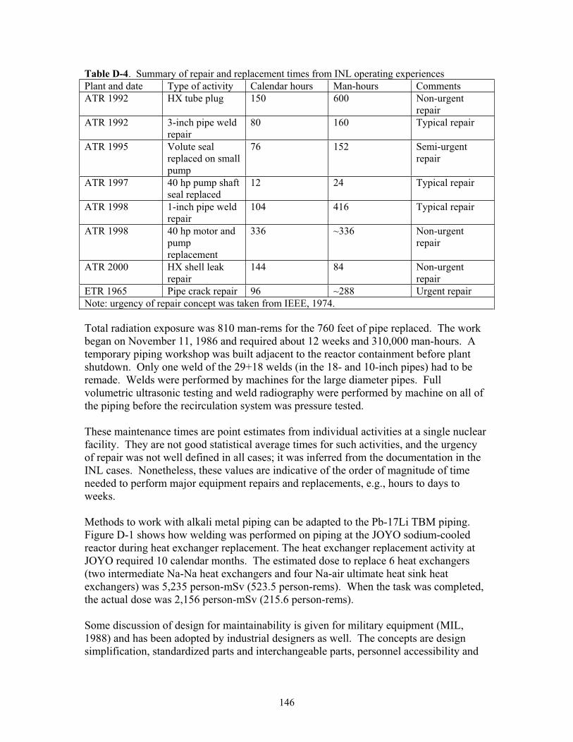
146
Table D-4. Summary of repair and replacement times from INL operating experiences Plant and date Type of activity Calendar hours Man-hours Comments ATR 1992 HX tube plug 150 600 Non-urgent
repairATR 1992 3-inch pipe weld
repair80 160 Typical repair
ATR 1995 Volute seal replaced on small pump
76 152 Semi-urgent repair
ATR 1997 40 hp pump shaft seal replaced
12 24 Typical repair
ATR 1998 1-inch pipe weld repair
104 416 Typical repair
ATR 1998 40 hp motor and pump replacement
336 ~336 Non-urgent repair
ATR 2000 HX shell leak repair
144 84 Non-urgent repair
ETR 1965 Pipe crack repair 96 ~288 Urgent repair Note: urgency of repair concept was taken from IEEE, 1974.
Total radiation exposure was 810 man-rems for the 760 feet of pipe replaced. The work began on November 11, 1986 and required about 12 weeks and 310,000 man-hours. A temporary piping workshop was built adjacent to the reactor containment before plant shutdown. Only one weld of the 29+18 welds (in the 18- and 10-inch pipes) had to be remade. Welds were performed by machines for the large diameter pipes. Full volumetric ultrasonic testing and weld radiography were performed by machine on all of the piping before the recirculation system was pressure tested.
These maintenance times are point estimates from individual activities at a single nuclear facility. They are not good statistical average times for such activities, and the urgency of repair was not well defined in all cases; it was inferred from the documentation in the INL cases. Nonetheless, these values are indicative of the order of magnitude of time needed to perform major equipment repairs and replacements, e.g., hours to days to weeks.
Methods to work with alkali metal piping can be adapted to the Pb-17Li TBM piping.Figure D-1 shows how welding was performed on piping at the JOYO sodium-cooled reactor during heat exchanger replacement. The heat exchanger replacement activity at JOYO required 10 calendar months. The estimated dose to replace 6 heat exchangers (two intermediate Na-Na heat exchangers and four Na-air ultimate heat sink heat exchangers) was 5,235 person-mSv (523.5 person-rems). When the task was completed, the actual dose was 2,156 person-mSv (215.6 person-rems).
Some discussion of design for maintainability is given for military equipment (MIL, 1988) and has been adopted by industrial designers as well. The concepts are design simplification, standardized parts and interchangeable parts, personnel accessibility and
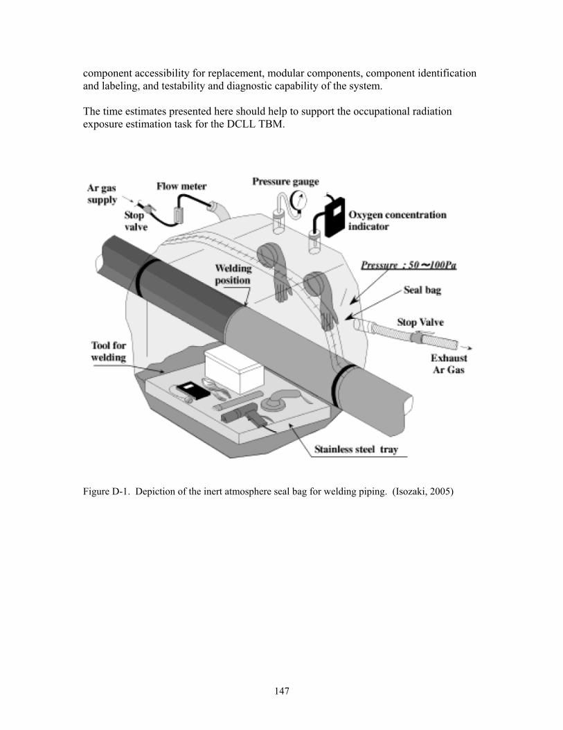
147
component accessibility for replacement, modular components, component identification and labeling, and testability and diagnostic capability of the system.
The time estimates presented here should help to support the occupational radiation exposure estimation task for the DCLL TBM.
Figure D-1. Depiction of the inert atmosphere seal bag for welding piping. (Isozaki, 2005)
148
APPENDIX D REFERENCES
Butler, 2000. D. Butler, Guide to Ship Repair Estimates (in Man-Hours), Butterworth Heinemann Publishers, Amsterdam, 2000.
Cavagna, 2006. Ch. Cavagna, O. Gastaldi, L. Martin, and V. Grabon, “Phenix Steam Generator Module Repair: Sodium Removal Process, Ultrasonic Controls, and Repair Method,” Nuclear Technology, 153 (2006) 274-281.
Chilton, 2007. Chilton Labor Guide Manual, 2007 edition, Thomson Delmar Learning, Clifton Park, NY, 2007.
Cullinane, 1989. M. J. Cullinane, Jr., “Reliability and Maintainability Data for Water Distribution System Components,” in L.W. Mays, editor, Reliability Analysis of Water Distribution Systems, American Society of Civil Engineers, New York, 1989, pages 225-246.
Derdiger, 1981. J. A. Derdiger, K. M. Bhatt, and W. E. Siegfriedt, Component Failure and Repair Data for Coal-fired Power Units, EPRI-AP-2071, Electric Power Research Institute, Palo Alto, CA, October 1981.
GA, 1978. G. W. Hannaman, GCR Reliability Data Bank Status Report, GA-A14839, General Atomic Company, San Diego, CA, July 1978.
Hashemian, 1993. H. M. Hashemian, D. W. Mitchell, K. M. Petersen, and C. S. Shell, Validation of Smart Sensor Technologies for Instrument Calibration Reduction in Nuclear Power Plants, NUREG/CR-5903, US Nuclear Regulatory Commission, Washington DC (1993).
Hummler, 1988. A. Hummler and R. Holz, “Recirculation loop replacement at boiling water reactors,” Kerntechnik, 52 (1988) 131-135.
IEEE, 1974. IEEE Committee Report, “Report on Reliability Survey of Industrial Plants, Part III: Causes and Types of Failures of Electrical Equipment, the Methods of Repair, and the Urgency of Repair,” IEEE Transactions on Industry Applications,10 (1974) 242-252.
IEEE, 1984. IEEE Guide to the Collection and Presentation of Electrical, Electronic, Sensing Component, and Mechanical Equipment Reliability Data for Nuclear-Power Generating Stations, IEEE Std 500-1984, Institute of Electrical and Electronics Engineers, New York, December 1983, Page 286.
IEEE, 1997. IEEE Recommended Practice for the Design of Reliable Industrial and Commercial Power Systems, IEEE Std 493-1997, Institute of Electrical and Electronics Engineers, New York, December 1997, Appendices A and H.
149
Isozaki, 2005. K. Isozaki, T. Ashida, K. Sumino, and S. Nakai, “Upgrade of Cooling System Heat Removal Capacity of the Experimental Fast Reactor JOYO,” Nuclear Technology, 150 (2005) 56-66.
Karassik, 1976. I. J. Karassik, W. C. Krutzsch, W. H. Fraser, and J. P. Messina, PumpHandbook, McGraw-Hill Book Company, New York, 1976, chapter 13.
Lofaro, 1991. R. Lofaro, “Monitoring of LWR Component Cooling Water Systems,” Proceedings of the International Meeting on Nuclear Power Plant and Facility Maintenance, Salt Lake City, Utah, April 7-10, 1991, American Nuclear Society, La Grange Park, IL, June 1991, volume 2, pages 597-605.
Matthews, 1968. R. R. Matthews and K. J. Henry, “Location and repair of the DFR leak,” Nuclear Engineering, 13 (1968) 840-844.
Means, 2007. Building Construction Cost Data 2007, sixty-fifth edition, RS Means Company, Kingston, MA, 2007.
MIL, 1988. Maintainability Design Techniques, DOD-HDBK-791, US Department of Defense, Washington, DC, March 1988.
Milivojevic, 1989. S. Milivojevic and J. R. Riznic, “The Empirical Failure Rate and Repair Rate of PWR Primary Coolant Pumps,” Reliability Engineering and System Safety, 24 (1989) 267-273.
Natalizio, 2005. A. Natalizio, T, Pinna, and J. D. Levine, “TFTR occupational radiation exposure data collection and analysis,” Fusion Engineering and Design, 75-79(2005) 1187-1191.
Natalizio, 2005a. A. Natalizio, M. T. Porfiri, and B. Patel, “Collection and analysis of occupational radiation exposure data from the JET tokamak,” Fusion Engineering and Design, 75-79 (2005) 1193-1197.
Olson, 1986. W. H. Olson, “The Impact of Radionuclides on Maintenance of Experimental Breeder Reactor II,” Argonne National Laboratory, CONF-860311-1, presented at the American Nuclear Society Topical Meeting on Nuclear Power Plant Maintenance, Salt Lake City, Utah, March 23-27, 1986.
Sandri, 2000. S. Sandri and L. Di Pace, “Occupational radiation exposure during the inspection and maintenance of the ITER water cooling system, a comparison between two working strategies,” Fusion Engineering and Design, 51-52 (2000) 445-551.
Sandri, 2002. S. Sandri and L. Di Pace, “Collective dose at ITER FEAT,” FusionEngineering and Design, 63-64 (2002) 199-203.
150
Sandri, 2004. S. Sandri, A. Coniglio, L. Di Pace, and M. Pillon, “Radiological safety of ITER personnel during normal operation and maintenance of the divertor,” Radiation Physics and Chemistry, 71 (2004) 809-810.
Shultz, 1982. D. W. Shultz and V. B. Parr, Evaluation and Documentation of Mechanical Reliability of Conventional Wastewater Treatment Plant Components, EPA-600/2-82-044, accession number PB82227539, US Environmental Protection Agency, Cincinnati, Ohio, March 1982.
Smith, 1966. E. H. Smith, J. L. Liebenthal, H. D. Killian, K. R. Hoopingarner, and R. A. Moen, Crack in the Engineering Test Reactor Primary Cooling System, IDO-17158, Phillips Petroleum Company, Atomic Energy Division, Idaho Operations Office, U.S. Atomic Energy Commission, March 1966.
WASH, 1975. Appendix III, “Failure Data,” to Reactor Safety Study, an Assessment of Accident Risks in U.S. Nuclear Power Plants, WASH-1400, NUREG-75/014, US Nuclear Regulatory Commission, October 1975.