Embed Size (px)
Citation preview
Kramer Electronics, Ltd.
Preliminary
USER MANUAL
Models: TP-104, TP-104HD, XGA Line Transmitter/DA
TP-105, TP-105(HD), CAT 5 Line Driver/DA
TP-121, XGA/Audio Line Transmitter
TP-122, XGA/Audio Line Receiver
TP-123, XGA/Audio/Data Line Transmitter
TP-124, XGA/Audio/Data Line Receiver
Contents
i
Contents
1 Introduction 1 2 Getting Started 1 2.1 Quick Start 2 3 Overview 4 3.1 Shielded Twisted Pair (STP)/Unshielded Twisted Pair (UTP) 4 3.2 About the Power Connect Feature 5 3.3 Recommendations for Achieving the Best Performance 5 4 Your TP-104/TP-104HD XGA Line Transmitter/DA 6 5 Your TP-105/TP-105(HD) CAT 5 Line Driver/DA 8 6 Your TP-121/TP-122 9 6.1 Your TP-121 XGA/Audio Line Transmitter 9 6.1.1 The TP-121 Internal Polarity Switches 10 6.2 Your TP-122 XGA/Audio Line Receiver 10 6.2.1 Your TP-122 XGA/Audio Line Receiver (Topside) 10 6.2.2 Your TP-122 XGA/Audio Line Receiver (Underside) 12 7 Your TP-123/TP-124 13 7.1 Your TP-123 XGA/Audio/Data Line Transmitter 13 7.1.1 The TP-123 Internal Polarity Switches 14 7.2 Your TP-124 XGA/Audio/Data Line Receiver 15 7.2.1 Your TP-124 XGA/Audio/Data Line Receiver (Underside) 16 8 Connecting the XGA/Audio Line Transmitter/Receiver 17 8.1 Wiring the CAT 5 LINE IN/LINE OUT RJ-45 Connectors 19 9 Connecting the XGA/Audio/Data Line Transmitter/Receiver 19 9.1 Controlling via RS-232 (for example, using a PC) 22 10 Configuring a 1:4 XGA to TP Transmitter/Receiver/DA 23 11 Configuring a TP-105 CAT 5 Line Driver/DA 25 12 Technical Specifications 27
Figures
Figure 1: TP-104 XGA Line Transmitter/DA 6 Figure 2: TP-104HD XGA Line Transmitter/DA 6 Figure 3: TP-104 (Underside Panel) 7 Figure 4: TP-105 CAT 5 Line Driver/DA 8 Figure 5: TP-121 XGA/Audio Line Transmitter 9 Figure 6: TP-121 Internal Polarity Switches 10 Figure 7: TP-122 XGA/Audio Line Receiver (Topside) 11 Figure 8: TP-122 XGA/Audio Line Receiver (Underside) 12 Figure 9: TP-123 XGA/Audio/Data Line Transmitter 13
KRAMER: SIMPLE CREATIVE TECHNOLOGY
Contents
ii
Figure 10: TP-123 Internal Polarity Switches 14 Figure 11: TP-124 XGA/Audio/Data Line Receiver (Topside) 15 Figure 12: TP-124 XGA/Audio/Data Line Receiver (Underside) 16 Figure 13: Connecting the XGA/Audio Line Transmitter/Receiver System 18 Figure 14: CAT 5 PINOUT 19 Figure 15: Connecting the XGA/Audio/Data Line Transmitter/Receiver System 21 Figure 16: RS-232 PINOUT Connection 22 Figure 17: Configuring a 1:4 XGA to Twisted Pair Transmitter/Receiver/DA 24 Figure 18: Configuring a TP-105 CAT 5 Line Driver/DA 26
Tables
Table 1: TP-104, TP-104HD XGA Line Transmitter/DA Features 7 Table 2: TP-104 (Underside Panel) Features 7 Table 3: TP-105 CAT 5 Line Driver/DA Features 8 Table 4: TP-121 XGA/Audio Line Transmitter Features 9 Table 5: Features of the TP-121 Internal Polarity Switches 10 Table 6: TP-122 XGA/Audio Line Receiver (Topside) Features 11 Table 7: TP-122 XGA/Audio Line Receiver (Underside) Features 12 Table 8: TP-123 XGA/Audio/Data Line Transmitter Features 14 Table 9: Features of the TP-123 Internal Polarity Switches 14 Table 10: TP-124 XGA/Audio/Data Line Receiver (Topside) Features 16 Table 11: TP-124 XGA/Audio/Data Line Receiver (Underside) Features 16 Table 12: CAT 5 PINOUT 19 Table 13: RS-232 PINOUT Connection 22 Table 14: Technical Specifications of the TP-104 and the TP-104HD 27 Table 15: Technical Specifications of the TP-105 and the TP-105(HD) 27 Table 16: Technical Specifications of the TP-121/TP-122/TP-123/TP-124 28
Introduction
1 1
1 Introduction
Welcome to Kramer Electronics! Since 1981, Kramer Electronics has been providing a world of unique, creative, and affordable solutions to the vast range of problems that confront the video, audio, presentation, and broadcasting professional on a daily basis. In recent years, we have redesigned and upgraded most of our line, making the best even better! Our 1,000-plus different models now appear in 11 groups1
Thank you for purchasing your Kramer TOOLS: TP-104, TP-104HD XGA Line Transmitter/DA, and/or TP-105, TP-105(HD), CAT 5 Line Driver/DA, and/or TP-121 XGA/Audio Line Transmitter, and/or TP-122 XGA/Audio Line Receiver, and/or TP-123, XGA/Audio/Data Line Transmitter, and/or TP-124, XGA/Audio/Data Line Receiver, which are ideal for:
that are clearly defined by function.
• Presentation and multimedia applications • Long range graphics distribution for schools, hospitals, security,
and stores
The package includes one or more of the following Kramer TOOLS: • TP-104/TP-104HD, TP-105/TP-105(HD), TP-121, TP-122,
TP-123, or TP-124 • Power adapter (12V DC) • This user manual2
2 Getting Started
We recommend that you: • Unpack the equipment carefully and save the original box and
packaging materials for possible future shipment • Review the contents of this user manual • Use Kramer high-performance high-resolution cables3
1 GROUP 1: Distribution Amplifiers; GROUP 2: Switchers and Matrix Switchers; GROUP 3: Control Systems; GROUP 4:
Format/Standards Converters; GROUP 5: Range Extenders and Repeaters; GROUP 6: Specialty AV Products; GROUP 7:
Scan Converters and Scalers; GROUP 8: Cables and Connectors; GROUP 9: Room Connectivity; GROUP 10: Accessories
and Rack Adapters; GROUP 11: Sierra Products
2 Download up-to-date Kramer user manuals at http://www.kramerelectronics.com
3 The complete list of Kramer cables is on our Web site at http://www.kramerelectronics.com
KRAMER: SIMPLE CREATIVE TECHNOLOGY
Getting Started
2
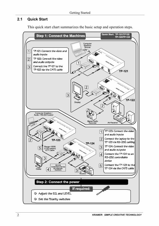
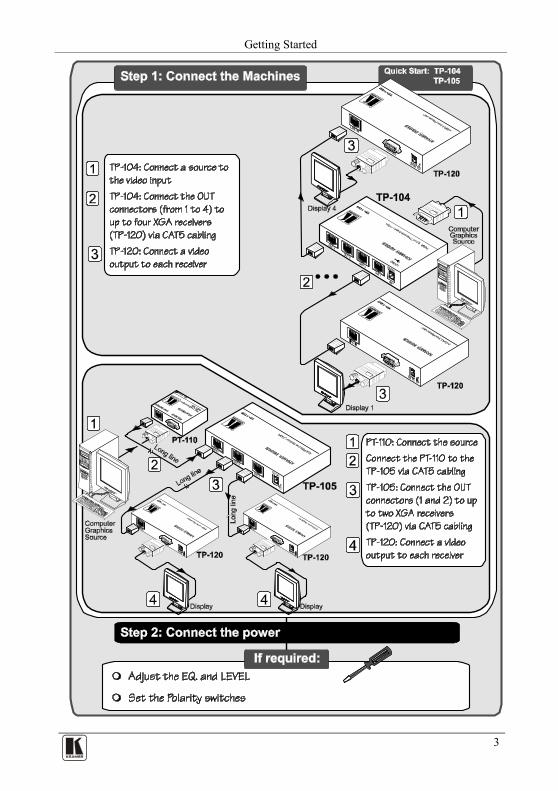
2.1 Quick Start
This quick start chart summarizes the basic setup and operation steps.
Getting Started
3 3
KRAMER: SIMPLE CREATIVE TECHNOLOGY
Overview
4
3 Overview
This user manual describes the following Kramer TOOLS: • TP-104/TP-104HD XGA Line Transmitter/DA is a line
transmitter/1:4 DA that receives an XGA signal and transmits it over four CAT 5 cables to appropriate receivers (see section 4)
• TP-105/TP-105(HD) CAT 5 Line Driver/DA receives a CAT 5 input1 5 and distributes it to two identical outputs (see section )
• TP-121 XGA/Audio Line Transmitter and the TP-122 XGA/Audio Line Receiver (see section 6)
• TP-123 XGA/Audio/Data Line Transmitter and the TP-124 XGA/Audio/Data Line Receiver (see section 7)
This section describes: • Using shielded twisted pair (STP)/unshielded twisted pair (UTP),
see section 3.1 • The power connect feature, see section 3.2 • Recommendations for achieving the best performance, see section
3.3
3.1 Shielded Twisted Pair (STP)/Unshielded Twisted Pair (UTP)
We recommend that you use Shielded Twisted Pair (STP) cable. There are different levels of STP cable available, and we advise you to use the best quality STP cable that you can afford. Our non-skew-free cable, Kramer BC-STP is intended for analog signals where skewing is not an issue. For cases where there is skewing, our UTP skew-free cable, Kramer BC-XTP, may be used. Bear in mind, though, that we advise using STP cables where possible, since the compliance to electromagnetic interference was tested using those cables.
Although Unshielded Twisted Pair (UTP) cable might be preferred for long range applications, the UTP cable should be installed far away from electric cables, motors and so on, which are prone to create electrical interference. However, since the use of UTP cable might cause inconformity to electromagnetic standards, Kramer does not commit to meeting the standard with UTP cable.
1 Video only
Overview
5 5
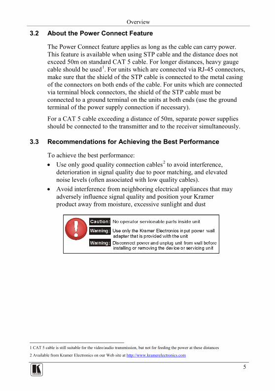
3.2 About the Power Connect Feature
The Power Connect feature applies as long as the cable can carry power. This feature is available when using STP cable and the distance does not exceed 50m on standard CAT 5 cable. For longer distances, heavy gauge cable should be used1
For a CAT 5 cable exceeding a distance of 50m, separate power supplies should be connected to the transmitter and to the receiver simultaneously.
. For units which are connected via RJ-45 connectors, make sure that the shield of the STP cable is connected to the metal casing of the connectors on both ends of the cable. For units which are connected via terminal block connectors, the shield of the STP cable must be connected to a ground terminal on the units at both ends (use the ground terminal of the power supply connection if necessary).
3.3 Recommendations for Achieving the Best Performance
To achieve the best performance: • Use only good quality connection cables2
• Avoid interference from neighboring electrical appliances that may adversely influence signal quality and position your Kramer product away from moisture, excessive sunlight and dust
to avoid interference, deterioration in signal quality due to poor matching, and elevated noise levels (often associated with low quality cables).
1 CAT 5 cable is still suitable for the video/audio transmission, but not for feeding the power at these distances
2 Available from Kramer Electronics on our Web site at http://www.kramerelectronics.com
KRAMER: SIMPLE CREATIVE TECHNOLOGY
Your TP-104/TP-104HD XGA Line Transmitter/DA
6
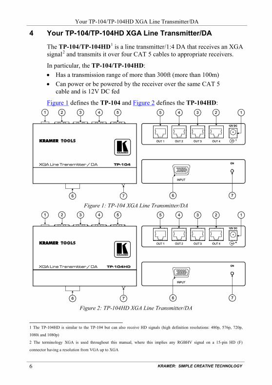
4 Your TP-104/TP-104HD XGA Line Transmitter/DA
The TP-104/TP-104HD1 is a line transmitter/1:4 DA that receives an XGA signal2
In particular, the TP-104/TP-104HD:
and transmits it over four CAT 5 cables to appropriate receivers.
• Has a transmission range of more than 300ft (more than 100m) • Can power or be powered by the receiver over the same CAT 5
cable and is 12V DC fed
Figure 1 defines the TP-104 and Figure 2 defines the TP-104HD:
Figure 1: TP-104 XGA Line Transmitter/DA
Figure 2: TP-104HD XGA Line Transmitter/DA
1 The TP-104HD is similar to the TP-104 but can also receive HD signals (high definition resolutions: 480p, 576p, 720p,
1080i and 1080p)
2 The terminology XGA is used throughout this manual, where this implies any RGBHV signal on a 15-pin HD (F)
connector having a resolution from VGA up to XGA
Your TP-104/TP-104HD XGA Line Transmitter/DA
7 7
Table 1: TP-104, TP-104HD XGA Line Transmitter/DA Features # Feature Function
1 12V DC +12V DC connector for powering the unit 2 OUT 4 RJ-45 connector Connects to1 the LINE IN RJ-45 connector on the TP-122 XGA/Audio Line
Receiver or the TP-120 XGA Line Receiver 2
3
OUT 3 RJ-45 connector Connects to1 the LINE IN RJ-45 connector on the TP-122 XGA/Audio Line Receiver or the TP-120 XGA Line Receiver2
4 OUT 2 RJ-45 connector Connects to1 the LINE IN RJ-45 connector on the TP-122 XGA/Audio Line Receiver or the TP-120 XGA Line Receiver2
5 OUT 1 RJ-45 connector Connects to1 the LINE IN RJ-45 connector on the TP-122 XGA/Audio Line Receiver or the TP-120 XGA Line Receiver2
6 INPUT 15-pin HD (F) connector Connect to the XGA source 7 ON LED Illuminates when receiving power
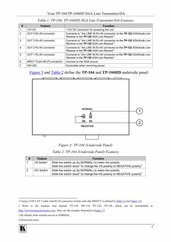
Figure 3 and Table 2 define the TP-104 and TP-104HD underside panel:
Figure 3: TP-104 (Underside Panel)
Table 2: TP-104 (Underside Panel) Features
# Feature Function 1 VS Switch Slide the switch up (to NORMAL) to retain the polarity
Slide the switch down3 to change the VS polarity to NEGATIVE polarity4
2
HS Switch Slide the switch up (to NORMAL) to retain the polarity Slide the switch down3 to change the HS polarity to NEGATIVE polarity4
1 Using a UTP CAT 5 cable with RJ-45 connectors at both ends (the PINOUT is defined in Table 12 and Figure 14)
2 Refer to the separate user manual: PT-110, WP-110, PT-120, TP-120, which can be downloaded at
http://www.kramerelectronics.com. Also, see the example illustrated in Figure 17
3 By default, both switches are set to NORMAL
4 Downward syncs
KRAMER: SIMPLE CREATIVE TECHNOLOGY
Your TP-105/TP-105(HD) CAT 5 Line Driver/DA
8
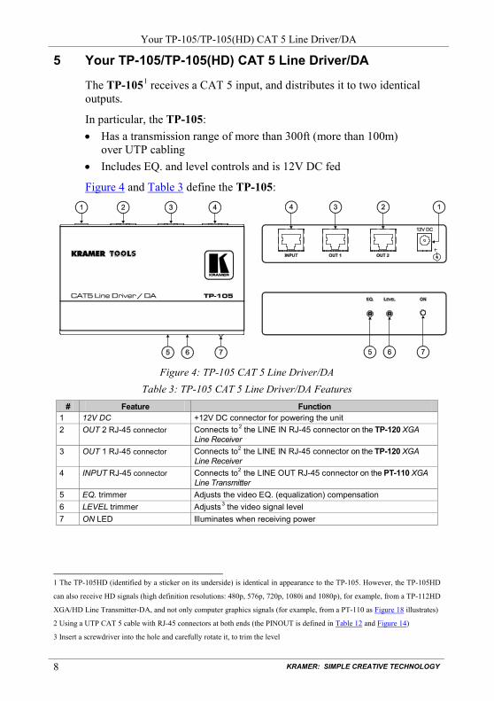
5 Your TP-105/TP-105(HD) CAT 5 Line Driver/DA
The TP-1051
In particular, the TP-105:
receives a CAT 5 input, and distributes it to two identical outputs.
• Has a transmission range of more than 300ft (more than 100m) over UTP cabling
• Includes EQ. and level controls and is 12V DC fed
Figure 4 and Table 3 define the TP-105:
Figure 4: TP-105 CAT 5 Line Driver/DA
Table 3: TP-105 CAT 5 Line Driver/DA Features # Feature Function
1 12V DC +12V DC connector for powering the unit 2 OUT 2 RJ-45 connector Connects to2
3
the LINE IN RJ-45 connector on the TP-120 XGA Line Receiver
OUT 1 RJ-45 connector Connects to2 the LINE IN RJ-45 connector on the TP-120 XGA Line Receiver
4 INPUT RJ-45 connector Connects to2 the LINE OUT RJ-45 connector on the PT-110 XGA Line Transmitter
5 EQ. trimmer Adjusts the video EQ. (equalization) compensation 6 LEVEL trimmer Adjusts3
7 the video signal level
ON LED Illuminates when receiving power
1 The TP-105HD (identified by a sticker on its underside) is identical in appearance to the TP-105. However, the TP-105HD
can also receive HD signals (high definition resolutions: 480p, 576p, 720p, 1080i and 1080p), for example, from a TP-112HD
XGA/HD Line Transmitter-DA, and not only computer graphics signals (for example, from a PT-110 as Figure 18 illustrates)
2 Using a UTP CAT 5 cable with RJ-45 connectors at both ends (the PINOUT is defined in Table 12 and Figure 14)
3 Insert a screwdriver into the hole and carefully rotate it, to trim the level
Your TP-121/TP-122
9 9
6 Your TP-121/TP-122
This section defines the TP-121 XGA/Audio Line Transmitter (see section 6.1), and the TP-122 XGA/Audio Line Receiver (see section 6.2).
6.1 Your TP-121 XGA/Audio Line Transmitter
The TP-121 is an XGA/audio stereo line transmitter that receives an XGA signal and an unbalanced stereo analog audio signal and transmits them over CAT 5 cable to a TP-122 receiver, converting the unbalanced stereo analog audio signal to digital audio (S/PDIF) stream before transmitting, thus preserving the quality of the audio signal. In particular, the TP-121: • Has a transmission range of more than 300ft (more than 100m), and a
20kHz audio bandwidth with an S/N ratio that exceeds 80dB on the same transmission range
• Can power or be powered by the receiver over the same CAT 5 cable • Is 12V DC fed
Figure 5 and Table 4 define the TP-121:
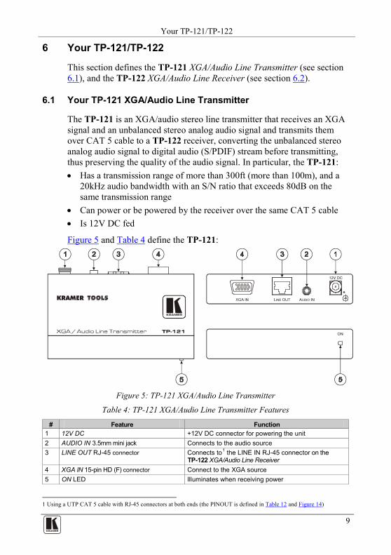
Figure 5: TP-121 XGA/Audio Line Transmitter
Table 4: TP-121 XGA/Audio Line Transmitter Features
# Feature Function 1 12V DC +12V DC connector for powering the unit 2 AUDIO IN 3.5mm mini jack Connects to the audio source 3 LINE OUT RJ-45 connector Connects to1
4
the LINE IN RJ-45 connector on the TP-122 XGA/Audio Line Receiver
XGA IN 15-pin HD (F) connector Connect to the XGA source 5 ON LED Illuminates when receiving power
1 Using a UTP CAT 5 cable with RJ-45 connectors at both ends (the PINOUT is defined in Table 12 and Figure 14)
KRAMER: SIMPLE CREATIVE TECHNOLOGY
Your TP-121/TP-122
10
6.1.1 The TP-121 Internal Polarity Switches
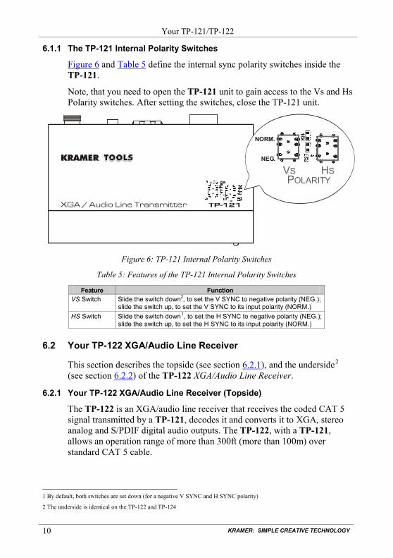
Figure 6 and Table 5 define the internal sync polarity switches inside the TP-121.
Note, that you need to open the TP-121 unit to gain access to the Vs and Hs Polarity switches. After setting the switches, close the TP-121 unit.
Figure 6: TP-121 Internal Polarity Switches
Table 5: Features of the TP-121 Internal Polarity Switches
Feature Function VS Switch Slide the switch down2, to set the V SYNC to negative polarity (NEG.);
slide the switch up, to set the V SYNC to its input polarity (NORM.) HS Switch Slide the switch down1
6.2 Your TP-122 XGA/Audio Line Receiver
, to set the H SYNC to negative polarity (NEG.); slide the switch up, to set the H SYNC to its input polarity (NORM.)
This section describes the topside (see section 6.2.1), and the underside2
6.2.2
(see section ) of the TP-122 XGA/Audio Line Receiver.
6.2.1 Your TP-122 XGA/Audio Line Receiver (Topside)
The TP-122 is an XGA/audio line receiver that receives the coded CAT 5 signal transmitted by a TP-121, decodes it and converts it to XGA, stereo analog and S/PDIF digital audio outputs. The TP-122, with a TP-121, allows an operation range of more than 300ft (more than 100m) over standard CAT 5 cable.
1 By default, both switches are set down (for a negative V SYNC and H SYNC polarity)
2 The underside is identical on the TP-122 and TP-124
NORM.
NEG.
Your TP-121/TP-122
11 11
In addition, the TP-122: • Can power or be powered by the transmitter over the same CAT 5
cable • Can change the polarity of decoding H and V Sync for video • Includes EQ. and level controls • Is 12V DC fed
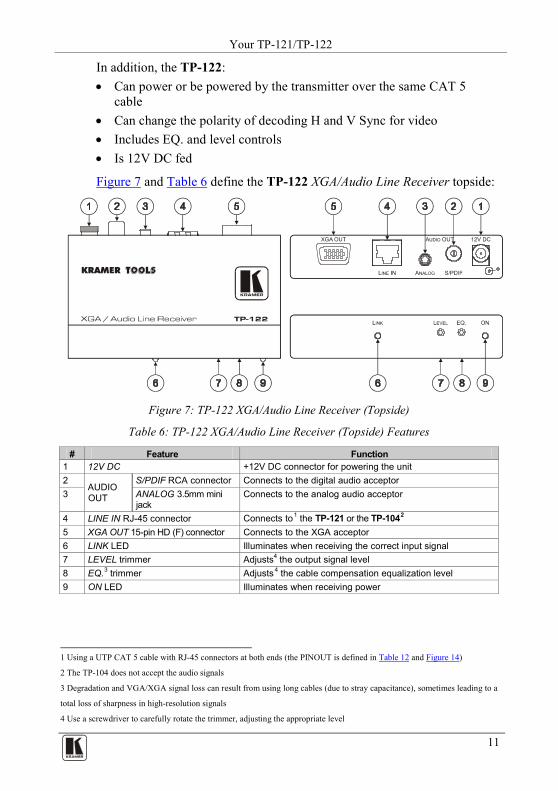
Figure 7 and Table 6 define the TP-122 XGA/Audio Line Receiver topside:
Figure 7: TP-122 XGA/Audio Line Receiver (Topside)
Table 6: TP-122 XGA/Audio Line Receiver (Topside) Features
# Feature Function 1 12V DC +12V DC connector for powering the unit 2
AUDIO OUT
S/PDIF RCA connector Connects to the digital audio acceptor 3 ANALOG 3.5mm mini
jack Connects to the analog audio acceptor
4 LINE IN RJ-45 connector Connects to1 the TP-121 or the TP-1042
5
XGA OUT 15-pin HD (F) connector Connects to the XGA acceptor 6 LINK LED Illuminates when receiving the correct input signal 7 LEVEL trimmer Adjusts4 the output signal level 8 EQ.3 Adjusts trimmer 4
9 the cable compensation equalization level
ON LED Illuminates when receiving power
1 Using a UTP CAT 5 cable with RJ-45 connectors at both ends (the PINOUT is defined in Table 12 and Figure 14)
2 The TP-104 does not accept the audio signals
3 Degradation and VGA/XGA signal loss can result from using long cables (due to stray capacitance), sometimes leading to a
total loss of sharpness in high-resolution signals
4 Use a screwdriver to carefully rotate the trimmer, adjusting the appropriate level
KRAMER: SIMPLE CREATIVE TECHNOLOGY
Your TP-121/TP-122
12
6.2.2 Your TP-122 XGA/Audio Line Receiver (Underside)
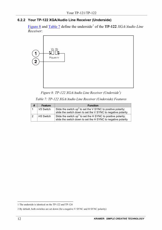
Figure 8 and Table 7 define the underside1
of the TP-122 XGA/Audio Line Receiver:
Figure 8: TP-122 XGA/Audio Line Receiver (Underside1)
Table 7: TP-122 XGA/Audio Line Receiver (Underside) Features
# Feature Function 1 VS Switch Slide the switch up2 to set the V SYNC to positive polarity;
slide the switch down to set the V SYNC to negative polarity 2 HS Switch Slide the switch up2
to set the H SYNC to positive polarity; slide the switch down to set the H SYNC to negative polarity
1 The underside is identical on the TP-122 and TP-124
2 By default, both switches are set down (for a negative V SYNC and H SYNC polarity)
Your TP-123/TP-124
13 13
7 Your TP-123/TP-124
This section describes the TP-123 XGA/Audio/Data Line Transmitter (see section 7.1), and the TP-124 XGA/Audio/Data Line Receiver (see section 7.2).
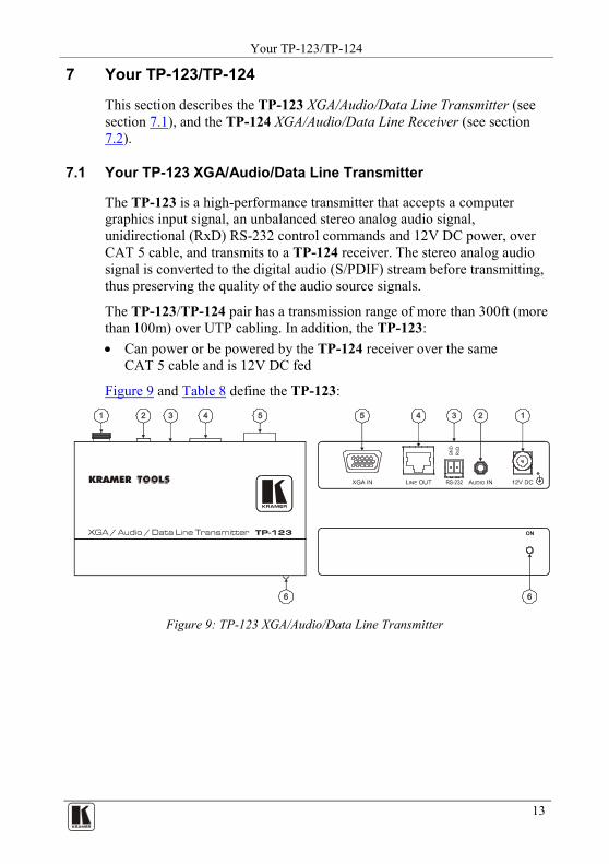
7.1 Your TP-123 XGA/Audio/Data Line Transmitter
The TP-123 is a high-performance transmitter that accepts a computer graphics input signal, an unbalanced stereo analog audio signal, unidirectional (RxD) RS-232 control commands and 12V DC power, over CAT 5 cable, and transmits to a TP-124 receiver. The stereo analog audio signal is converted to the digital audio (S/PDIF) stream before transmitting, thus preserving the quality of the audio source signals.
The TP-123/TP-124 pair has a transmission range of more than 300ft (more than 100m) over UTP cabling. In addition, the TP-123: • Can power or be powered by the TP-124 receiver over the same
CAT 5 cable and is 12V DC fed
Figure 9 and Table 8 define the TP-123:
Figure 9: TP-123 XGA/Audio/Data Line Transmitter
KRAMER: SIMPLE CREATIVE TECHNOLOGY
Your TP-123/TP-124
14
Table 8: TP-123 XGA/Audio/Data Line Transmitter Features
# Feature Function 1 12V DC +12V DC connector for powering the unit 2 AUDIO IN 3.5mm mini jack Connects to the audio source 3 RS-232 terminal block connector Connects to the PC or the Remote Controller (see section 9.1) 4 LINE OUT RJ-45 connector Connects to1
5
the LINE IN RJ-45 connector on the TP-124 XGA/Audio Line Receiver
XGA IN 15-pin HD (F) connector Connect to the XGA source 6 ON LED Illuminates when receiving power
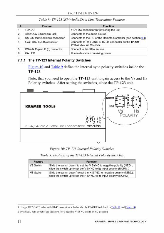
7.1.1 The TP-123 Internal Polarity Switches
Figure 10 and Table 9 define the internal sync polarity switches inside the TP-123.
Note, that you need to open the TP-123 unit to gain access to the Vs and Hs Polarity switches. After setting the switches, close the TP-123 unit.
Figure 10: TP-123 Internal Polarity Switches
Table 9: Features of the TP-123 Internal Polarity Switches
Feature Function VS Switch Slide the switch down2 to set the V SYNC to negative polarity (NEG.);
slide the switch up to set the V SYNC to its input polarity (NORM.) HS Switch Slide the switch down2
to set the H SYNC to negative polarity (NEG.); slide the switch up to set the H SYNC to its input polarity (NORM.)
1 Using a UTP CAT 5 cable with RJ-45 connectors at both ends (the PINOUT is defined in Table 12 and Figure 14)
2 By default, both switches are set down (for a negative V SYNC and H SYNC polarity)
NORM.
NEG.
Your TP-123/TP-124
15 15
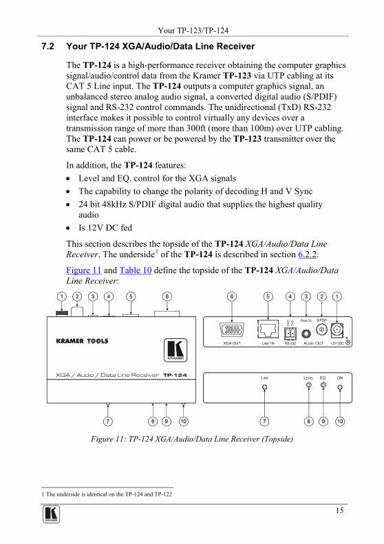
7.2 Your TP-124 XGA/Audio/Data Line Receiver
The TP-124 is a high-performance receiver obtaining the computer graphics signal/audio/control data from the Kramer TP-123 via UTP cabling at its CAT 5 Line input. The TP-124 outputs a computer graphics signal, an unbalanced stereo analog audio signal, a converted digital audio (S/PDIF) signal and RS-232 control commands. The unidirectional (TxD) RS-232 interface makes it possible to control virtually any devices over a transmission range of more than 300ft (more than 100m) over UTP cabling. The TP-124 can power or be powered by the TP-123 transmitter over the same CAT 5 cable.
In addition, the TP-124 features: • Level and EQ. control for the XGA signals • The capability to change the polarity of decoding H and V Sync • 24 bit 48kHz S/PDIF digital audio that supplies the highest quality
audio • Is 12V DC fed
This section describes the topside of the TP-124 XGA/Audio/Data Line Receiver. The underside1 6.2.2 of the TP-124 is described in section .
Figure 11 and Table 10 define the topside of the TP-124 XGA/Audio/Data Line Receiver:
Figure 11: TP-124 XGA/Audio/Data Line Receiver (Topside)
1 The underside is identical on the TP-124 and TP-122

KRAMER: SIMPLE CREATIVE TECHNOLOGY
Your TP-123/TP-124
16
Table 10: TP-124 XGA/Audio/Data Line Receiver (Topside) Features
# Feature Function 1 12V DC +12V DC connector for powering the unit 2
AU
DIO
O
UT S/PDIF RCA connector Connects to the digital audio acceptor
3 ANALOG 3.5mm mini jack Connects to the analog audio acceptor
4 RS-232 Terminal Block connector Connects to the controlled unit 5 LINE IN RJ-45 connector Connects to1 the LINE OUT RJ-45 connector on the TP-123 or
the TP-1042
6
XGA OUT 15-pin HD (F) connector Connect to the XGA acceptor 7 LINK LED Illuminates when receiving the correct input signal 8 LEVEL trimmer Adjusts4 the output signal level 9 EQ.3 Adjusts trimmer 4
10 the cable compensation equalization level
ON LED Illuminates when receiving power
7.2.1 Your TP-124 XGA/Audio/Data Line Receiver (Underside)
Figure 12 and Table 11 define the underside5
of the TP-124 XGA/Audio /Data Line Receiver:
Figure 12: TP-124 XGA/Audio/Data Line Receiver (Underside1)
Table 11: TP-124 XGA/Audio/Data Line Receiver (Underside) Features
# Feature Function 1 VS Switch Slide the switch up2 to set the V SYNC to positive polarity;
slide the switch down to set the V SYNC to negative polarity 2 HS Switch Slide the switch up6
1 Using a UTP cable with CAT 5 connectors at both ends (the PINOUT is defined in
to set the H SYNC to positive polarity; slide the switch down to set the H SYNC to negative polarity
Table 12 and Figure 14)
2 The TP-104 does not accept the audio signals
3 Degradation and VGA/XGA signal loss can result from using long cables (due to stray capacitance), sometimes leading to a
total loss of sharpness in high-resolution signals
4 Use a screwdriver to carefully rotate the trimmer, adjusting the appropriate level
5 The underside is identical on the TP-122 and TP-124
6 By default, both switches are set down (for a negative V SYNC and H SYNC polarity)
Connecting the XGA/Audio Line Transmitter/Receiver
17 17
8 Connecting the XGA/Audio Line Transmitter/Receiver
You can use the TP-121 and TP-122 to configure an XGA/Audio Line-to-Twisted Pair Transmitter and Receiver system.
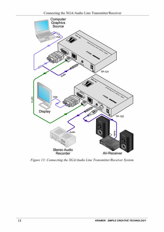
To connect the TP-121 XGA/Audio Line Transmitter with the TP-122 XGA/Audio Line Receiver, as the example in Figure 13 illustrates, do the following: 1. On the TP-121, connect the XGA source (for example, a laptop’s graphics
card) to the XGA INPUT 15-pin HD (F) connector and an audio source to the AUDIO IN 3.5mm mini jack, for example, using a Kramer C-GMA/GMA cable (VGA 15-pin HD (M) +Audio jack to VGA 15-pin HD (M) +Audio jack)1
2. On the TP-122, connect the XGA OUT 15-pin HD (F) connector to the XGA acceptor (for example, a display), and connect the AUDIO OUT S/PDIF RCA connector to the digital audio acceptor (for example, an AV Receiver), and the ANALOG 3.5mm mini jack to the analog audio acceptor (for example, a stereo audio recorder).
. Alternatively, you can connect an XGA source to the XGA INPUT 15-pin HD (F) connector, and a separate audio source to the AUDIO IN 3.5mm mini jack.
3. Connect the LINE OUTPUT RJ-45 connector on the TP-121 to the LINE IN RJ-45 connector on the TP-122, via UTP cabling (with a range of more than 300ft (>100m)), see section 8.1.
4. Connect the 12V DC power adapter to the power socket and connect the adapter to the mains electricity on both2
5. On the TP-122:
the TP-121 and the TP-122. The signal from the XGA source is transmitted via CAT 5 cable, decoded and converted at the XGA OUT 15-pin HD (F) connector to the XGA acceptor.
Adjust3
If necessary, set the H SYNC and V SYNC switches
the video output signal level and/or cable compensation equalization level, if required
4
1 Not supplied. The complete list of Kramer cables is on our Web site at
, on the underside
http://www.kramerelectronics.com
2 If you cannot connect the power to both the TP-121 and TP-122, you can just connect the power to the TP-122
3 Use a screwdriver to carefully rotate the trimmer, adjusting the appropriate level
4 By default, both switches are set down (for negative V SYNC and H SYNC polarity)
KRAMER: SIMPLE CREATIVE TECHNOLOGY
Connecting the XGA/Audio Line Transmitter/Receiver
18
Figure 13: Connecting the XGA/Audio Line Transmitter/Receiver System
Connecting the XGA/Audio/Data Line Transmitter/Receiver
19 19
8.1 Wiring the CAT 5 LINE IN/LINE OUT RJ-45 Connectors
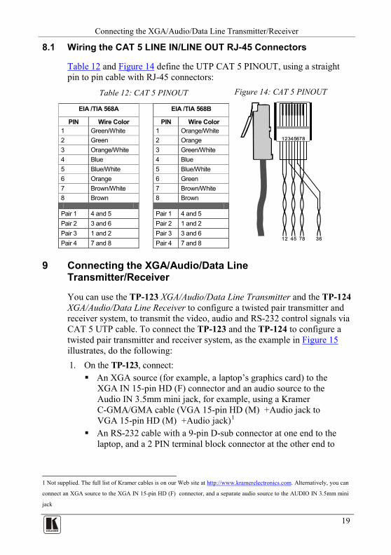
Table 12 and Figure 14 define the UTP CAT 5 PINOUT, using a straight pin to pin cable with RJ-45 connectors:
Table 12: CAT 5 PINOUT Figure 14: CAT 5 PINOUT
EIA /TIA 568A EIA /TIA 568B
PIN Wire Color PIN Wire Color 1 Green/White 1 Orange/White 2 Green 2 Orange 3 Orange/White 3 Green/White 4 Blue 4 Blue 5 Blue/White 5 Blue/White 6 Orange 6 Green 7 Brown/White 7 Brown/White 8 Brown 8 Brown
Pair 1 4 and 5 Pair 1 4 and 5 Pair 2 3 and 6 Pair 2 1 and 2 Pair 3 1 and 2 Pair 3 3 and 6 Pair 4 7 and 8 Pair 4 7 and 8
9 Connecting the XGA/Audio/Data Line Transmitter/Receiver
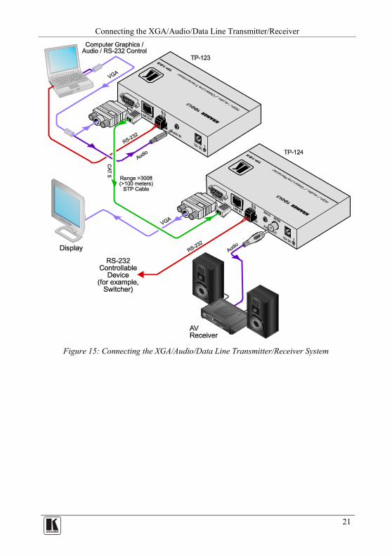
You can use the TP-123 XGA/Audio/Data Line Transmitter and the TP-124 XGA/Audio/Data Line Receiver to configure a twisted pair transmitter and receiver system, to transmit the video, audio and RS-232 control signals via CAT 5 UTP cable. To connect the TP-123 and the TP-124 to configure a twisted pair transmitter and receiver system, as the example in Figure 15 illustrates, do the following: 1. On the TP-123, connect: An XGA source (for example, a laptop’s graphics card) to the
XGA IN 15-pin HD (F) connector and an audio source to the Audio IN 3.5mm mini jack, for example, using a Kramer C-GMA/GMA cable (VGA 15-pin HD (M) +Audio jack to VGA 15-pin HD (M) +Audio jack)1
An RS-232 cable with a 9-pin D-sub connector at one end to the laptop, and a 2 PIN terminal block connector at the other end to
1 Not supplied. The full list of Kramer cables is on our Web site at http://www.kramerelectronics.com. Alternatively, you can
connect an XGA source to the XGA IN 15-pin HD (F) connector, and a separate audio source to the AUDIO IN 3.5mm mini
jack
KRAMER: SIMPLE CREATIVE TECHNOLOGY
Connecting the XGA/Audio/Data Line Transmitter/Receiver
20
the TP-123 RS-232 port1
2. On the TP-124, connect:
The XGA OUT 15-pin HD (F) connector to a display The S/PDIF Audio OUT RCA connector to a digital AV
Receiver (leave the ANALOG Audio OUT 3.5mm mini jack unconnected)
An RS-232 cable with a 2 PIN terminal block connector at one end to the TP-124 RS-232 port1, and a 9-pin D-sub connector at the other end to the RS-232 port on an RS-232 controllable device (for example, a switcher)
3. Connect the Line OUT RJ-45 connector on the TP-123 to the LINE IN RJ-45 connector on the TP-124, via UTP cabling2
4. Connect the 12V DC power adapter to the power socket and connect the adapter to the mains electricity on both
(with a range of more than 300ft (>100m)).
3
5. On the TP-124: the TP-123 and the TP-124.
Adjust4
If necessary, set the H SYNC and V SYNC switches
the video output signal level and/or cable compensation equalization level, if required
5
1 As defined in
, on the underside
Figure 16 and Table 13
2 For details of how to wire a CAT 5 LINE IN/LINE OUT RJ-45 connector, see section 8.1
3 If you cannot connect the power to both the TP-123 and TP-124, you can just connect the power to any one unit
4 Use a screwdriver to carefully rotate the trimmer, adjusting the appropriate level
5 By default, both switches are set down (for negative V SYNC and H SYNC polarity)
Connecting the XGA/Audio/Data Line Transmitter/Receiver
21 21
Figure 15: Connecting the XGA/Audio/Data Line Transmitter/Receiver System
KRAMER: SIMPLE CREATIVE TECHNOLOGY
Connecting the XGA/Audio/Data Line Transmitter/Receiver
22
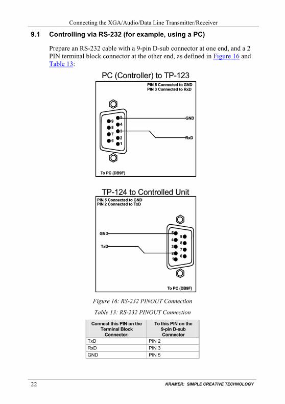
9.1 Controlling via RS-232 (for example, using a PC)
Prepare an RS-232 cable with a 9-pin D-sub connector at one end, and a 2 PIN terminal block connector at the other end, as defined in Figure 16 and Table 13:
Figure 16: RS-232 PINOUT Connection
Table 13: RS-232 PINOUT Connection
Connect this PIN on the Terminal Block
Connector:
To this PIN on the 9-pin D-sub Connector
TxD PIN 2 RxD PIN 3 GND PIN 5
Configuring a 1:4 XGA to TP Transmitter/Receiver/DA
23 23
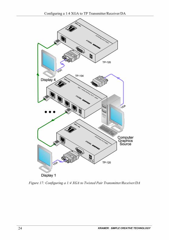
10 Configuring a 1:4 XGA to TP Transmitter/Receiver/DA
You can use the TP-104 XGA Line Transmitter/DA with the TP-120 XGA Line Receiver 1
To connect the TP-104 to four TP-120 units, as the example in
to configure a 1:4 XGA-to-Twisted Pair DA system.
Figure 17 illustrates, do the following: 1. On the TP-104, connect the XGA source (for example, a computer
graphics source) to the XGA INPUT 15-pin HD (F) connector, and connect the line output RJ-45 connector2
OUT 1 to the LINE IN RJ-45 connector on the TP-120 Unit I :
OUT 2 to the LINE IN RJ-45 connector on the TP-120 Unit II OUT 3 to the LINE IN RJ-45 connector on the TP-120 Unit III OUT 4 to the LINE IN RJ-45 connector on the TP-120 Unit IV
2. On the four TP-120 units, connect the: XGA OUT 15-pin HD (F) connector of Unit I to the XGA
acceptor (for example, Display 1) XGA OUT 15-pin HD (F) connector of Unit II to the XGA
acceptor (for example, Display 2) XGA OUT 15-pin HD (F) connector of Unit III to the XGA
acceptor (for example, Display 3) XGA OUT 15-pin HD (F) connector of Unit IV to the XGA
acceptor (for example, Display 4) 3. On each of the five Kramer TOOLS, connect the 12V DC power adapter to
the power socket and connect the adapter to the mains electricity. The signal from the XGA source is transmitted via the four CAT 5 cables, decoded and converted at the each of the XGA OUT 15-pin HD (F) connectors to the XGA acceptors.
4. On each of the five Kramer TOOLS: Adjust3
If necessary, on the TP-120 units, set the H SYNC and V SYNC switches
the video output signal level and/or cable compensation equalization level, if required
4
1 Refer to the separate user manual: PT-110, WP-110, PT-120, TP-120, which can be downloaded at
, on the underside
http://www.kramerelectronics.com
2 Via UTP cabling (with a range of more than 300ft (>100m)). For details of how to wire a CAT 5 LINE IN/LINE OUT
RJ-45 connector, see section 8.1
3 Use a screwdriver to carefully rotate the trimmer, adjusting the appropriate level
4 By default, both switches are set down (for negative V SYNC and H SYNC polarity)
KRAMER: SIMPLE CREATIVE TECHNOLOGY
Configuring a 1:4 XGA to TP Transmitter/Receiver/DA
24
Figure 17: Configuring a 1:4 XGA to Twisted Pair Transmitter/Receiver/DA
Configuring a TP-105 CAT 5 Line Driver/DA
25 25
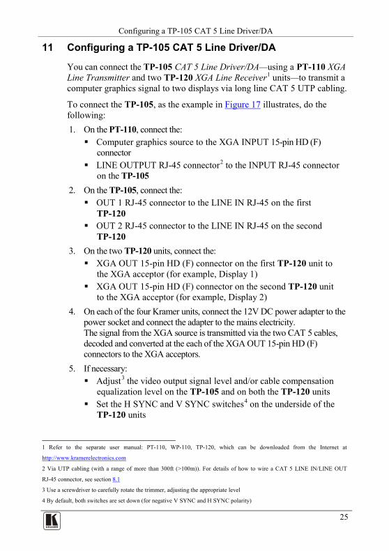
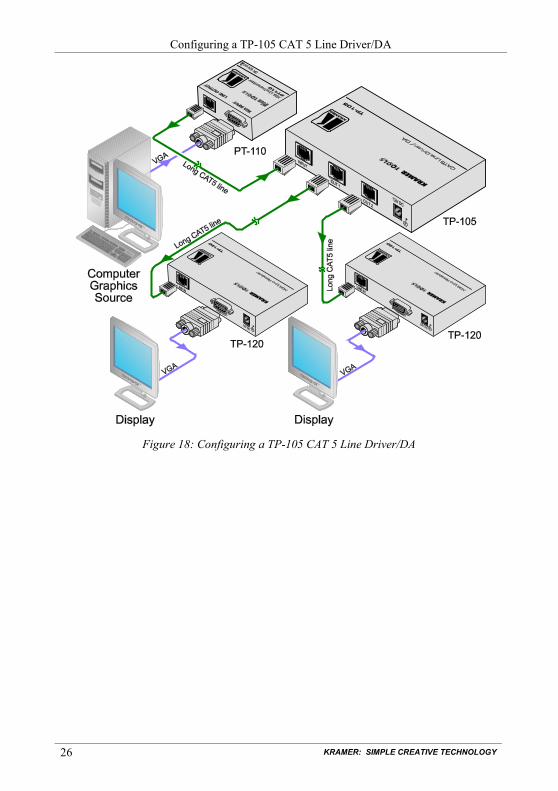
11 Configuring a TP-105 CAT 5 Line Driver/DA
You can connect the TP-105 CAT 5 Line Driver/DA—using a PT-110 XGA Line Transmitter and two TP-120 XGA Line Receiver1
To connect the TP-105, as the example in
units—to transmit a computer graphics signal to two displays via long line CAT 5 UTP cabling.
Figure 17 illustrates, do the following: 1. On the PT-110, connect the: Computer graphics source to the XGA INPUT 15-pin HD (F)
connector LINE OUTPUT RJ-45 connector2
2. On the TP-105, connect the:
to the INPUT RJ-45 connector on the TP-105
OUT 1 RJ-45 connector to the LINE IN RJ-45 on the first TP-120
OUT 2 RJ-45 connector to the LINE IN RJ-45 on the second TP-120
3. On the two TP-120 units, connect the: XGA OUT 15-pin HD (F) connector on the first TP-120 unit to
the XGA acceptor (for example, Display 1) XGA OUT 15-pin HD (F) connector on the second TP-120 unit
to the XGA acceptor (for example, Display 2) 4. On each of the four Kramer units, connect the 12V DC power adapter to the
power socket and connect the adapter to the mains electricity. The signal from the XGA source is transmitted via the two CAT 5 cables, decoded and converted at the each of the XGA OUT 15-pin HD (F) connectors to the XGA acceptors.
5. If necessary: Adjust3
Set the H SYNC and V SYNC switches
the video output signal level and/or cable compensation equalization level on the TP-105 and on both the TP-120 units
4
1 Refer to the separate user manual: PT-110, WP-110, TP-120, which can be downloaded from the Internet at
on the underside of the TP-120 units
http://www.kramerelectronics.com
2 Via UTP cabling (with a range of more than 300ft (>100m)). For details of how to wire a CAT 5 LINE IN/LINE OUT
RJ-45 connector, see section 8.1
3 Use a screwdriver to carefully rotate the trimmer, adjusting the appropriate level
4 By default, both switches are set down (for negative V SYNC and H SYNC polarity)
KRAMER: SIMPLE CREATIVE TECHNOLOGY
Configuring a TP-105 CAT 5 Line Driver/DA
26
Figure 18: Configuring a TP-105 CAT 5 Line Driver/DA
Technical Specifications
27 27
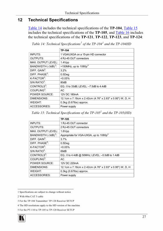
12 Technical Specifications
Table 14 includes the technical specifications of the TP-104, Table 15 includes the technical specifications of the TP-105, and Table 16 includes the technical specifications of the TP-121, TP-122, TP-123, and TP-124:
Table 14: Technical Specifications1 of the TP-1042
and the TP-104HD
TP-104 INPUTS: 1 VGA/UXGA on a 15-pin HD connector OUTPUTS: 4 RJ-45 OUT connectors MAX. OUTPUT LEVEL: 1.4Vpp BANDWIDTH (-3dB)3 >150MHz, up to 1080p: 4
DIFF. GAIN
3: 3.2% DIFF. PHASE3: 0.5Deg K-FACTOR3: <0.05% S/N RATIO3: 80dB CONTROLS3: EQ.: 0 to 33dB; LEVEL: –7.5dB to 4.4dB COUPLING3: AC POWER SOURCE: 12V DC 180mA DIMENSIONS: 12.1cm x 7.18cm x 2.42cm (4.76" x 2.83" x 0.95") W, D, H WEIGHT: 0.3kg (0.67lbs) approx. ACCESSORIES: Power supply
Table 15: Technical Specifications of the TP-1052 and the TP-105(HD)
TP-105 INPUTS: 1 RJ-45 OUT connector OUTPUTS: 2 RJ-45 OUT connectors MAX. OUTPUT LEVEL: 1.6Vpp BANDWIDTH (-3dB)5 Appropriate for VGA-UXGA, up to 1080p: 4 DIFF. GAIN5: 3.7% DIFF. PHASE5: 0.5Deg K-FACTOR5: <0.05% S/N RATIO5: 69dB CONTROLS5: EQ.: 0 to 4.4dB @ 50MHz; LEVEL: –5.5dB to 1.4dB COUPLING5: AC POWER SOURCE: 12V DC 220mA DIMENSIONS: 12.1cm x 7.18cm x 2.42cm (4.76" x 2.83" x 0.95") W, D, H WEIGHT: 0.3kg (0.67lbs) approx. ACCESSORIES: Power supply
1 Specifications are subject to change without notice
2 With 60m CAT 5 cable
3 For the TP-104 Transmitter/ TP-120 Receiver SETUP
4 The HD resolutions apply to the HD version of the machine
5 For the PT-110 to TP-105 to TP-120 Receiver SETUP
KRAMER: SIMPLE CREATIVE TECHNOLOGY
Technical Specifications
28
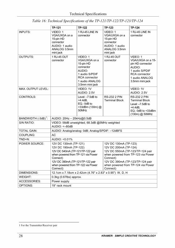
Table 16: Technical Specifications of the TP-121/TP-122/TP-123/TP-124
TP-121 TP-122 TP-123 TP-124 INPUTS: VIDEO: 1
VGA/UXGA on a 15-pin HD connector AUDIO: 1 audio ANALOG 3.5mm mini jack
1 RJ-45 LINE IN connector
VIDEO: 1 VGA/UXGA on a 15-pin HD connector AUDIO: 1 audio ANALOG 3.5mm mini jack
1 RJ-45 LINE IN connector
OUTPUTS: 1 RJ-45 OUT connector
VIDEO: 1 VGA/UXGA on a 15-pin HD connector AUDIO: 1 audio S/PDIF RCA connector 1 audio ANALOG 3.5mm mini jack
1 RJ-45 OUT connector
VIDEO: 1 VGA/UXGA on a 15-pin HD connector AUDIO: 1 audio S/PDIF RCA connector 1 audio ANALOG 3.5mm mini jack
MAX. OUTPUT LEVEL: VIDEO: 1V AUDIO: 2.5V
VIDEO: 1V AUDIO: 2.5V
CONTROLS: Level: –7.5dB to +4.4dB, EQ.: 0dB to +33dBm (130m) @ 50MHz
RS-232 2 PIN Terminal Block
RS-232 2 PIN Terminal Block Level: –7.5dB to +4.4dB, EQ.: 0dB to +33dBm (130m) @ 50MHz
BANDWIDTH (-3dB)1 AUDIO: 20Hz – [email protected] : S/N RATIO: VIDEO: 58dB unweighted, 68.3dB @5MHz weighted
AUDIO: <–80dB TOTAL GAIN: AUDIO: Analog/analog: 0dB; Analog/SPDIF: –12dBFS COUPLING: AC TND+N: AUDIO: <0.01% POWER SOURCE: 12V DC 130mA (TP-121)
12V DC 190mA (TP-122) 12V DC 540mA (TP-121/TP-122 pair when powered from TP-121 via Power Connect) 12V DC 390mA (TP-121/TP-122 pair when powered from TP-122 via Power Connect)
12V DC 130mA (TP-123) 12V DC 200mA (TP-124) 12V DC 550mA (TP-123/TP-124 pair when powered from TP-123 via Power Connect) 12V DC 390mA (TP-123/TP-124 pair when powered from TP-124 via Power Connect)
DIMENSIONS: 12.1cm x 7.18cm x 2.42cm (4.76" x 2.83" x 0.95") W, D, H WEIGHT: 0.3kg (0.67lbs) approx. ACCESSORIES: Power supply OPTIONS: 19” rack mount
1 For the Transmitter/Receiver pair
29 29
LIMITED WARRANTY
WHO IS PROTECTED?
WHAT IS COVERED AND WHAT IS NOT COVERED
WHAT WE WILL PAY FOR AND WHAT WE WILL NOT PAY FOR
HOW YOU CAN GET WARRANTY SERVICE
LIMITATION OF IMPLIED WARRANTIES
EXCLUSION OF DAMAGES
CAUTION!
Kramer Electronics (hereafter ) warrants this product free from defects in material and workmanship under the following terms.
Kramer
HOW LONG IS THE WARRANTYLabor and parts are warranted for seven years from the date of the first customer purchase.
Only the first purchase customer may enforce this warranty.
We will pay labor and material expenses for covered items. We will not pay for the following:
The liability of Kramer for any effective products is limited to the repair or replacement of the product at our option. Kramer shall not be liable for:
This warranty gives you specific legal rights, and you may also have other rights, which vary from place to place. All products returned to Kramer for service must have prior approval. This may be obtained from your dealer.
This equipment has been tested to determine compliance with the requirements of:
EN-50081: "Electromagnetic compatibility (EMC);generic emission standard.
Residential, commercial and light industry"EN-50082: "Electromagnetic compatibility (EMC) generic immunity standard.
Part 1: Residential, commercial and light industry environment".CFR-47: FCC* Rules and Regulations:
Part 15: “Radio frequency devicesSubpart B Unintentional radiators”
Except as below, this warranty covers all defects in material or workmanship in this product. The following are not covered by the warranty:1. Any product which is not distributed by Kramer, or which is not purchased from an authorized Kramer dealer. If you are
uncertain as to whether a dealer is authorized, please contact Kramer at one of the agents listed in the Web site www.kramerelectronics.com.
2. Any product, on which the serial number has been defaced, modified or removed, or on which the WARRANTY VOID TAMPERED sticker has been torn,
3. Damage, deterioration or malfunction resulting from:i) Accident, misuse, abuse, neglect, fire, water, lightning or other acts of natureii) Product modification, or failure to follow instructions supplied with the productiii) Repair or attempted repair by anyone not authorized by Krameriv) Any shipment of the product (claims must be presented to the carrier)v) Removal or installation of the productvi) Any other cause, which does not relate to a product defectvii) Cartons, equipment enclosures, cables or accessories used in conjunction with the product
1. Removal or installations charges.2. Costs of initial technical adjustments (set-up), including adjustment of user controls or programming. These costs are the
responsibility of the Kramer dealer from whom the product was purchased.3. Shipping charges.
1. To obtain service on you product, you must take or ship it prepaid to any authorized Kramer service center.2. Whenever warranty service is required, the original dated invoice (or a copy) must be presented as proof of warranty
coverage, and should be included in any shipment of the product. Please also include in any mailing a contact name, company, address, and a description of the problem(s).
3. For the name of the nearest Kramer authorized service center, consult your authorized dealer.
All implied warranties, including warranties of merchantability and fitness for a particular purpose, are limited in duration to the length of this warranty.
1. Damage to other property caused by defects in this product, damages based upon inconvenience, loss of use of the product, loss of time, commercial loss; or:
2. Any other damages, whether incidental, consequential or otherwise. Some countries may not allow limitations on how long an implied warranty lasts and/or do not allow the exclusion or limitation of incidental or consequential damages, so the above limitations and exclusions may not apply to you.
Servicing the machines can only be done by an authorized Kramer technician. Any user who makes changes or modifications to the unit without the expressed approval of the manufacturer will void user authority to operate the equipment.Use the supplied DC power supply to feed power to the machine.Please use recommended interconnection cables to connect the machine to other components.
IF reattached, removed or otherwise interfered with.
* FCC and CE approved using STP cable (for twisted pair products)
NOTE:
Part 1:

Kramer Electronics, Ltd. Web site: www.kramerelectronics.com
E-mail: [email protected] P/N: 2900-000037 REV 9
For the latest information on our products and a list of Kramer distributors, visit our Web site: www.kramerelectronics.com,
where updates to this user manual may be found. We welcome your questions, comments and feedback.
Caution
Safety Warning: Disconnect the unit from the power supply before opening/servicing.
P/N: 2900- 000037 Rev: 9