Embed Size (px)
Citation preview

Bellaterra 12/03/2007
Reference 06/31700676i
To Tornilleria Industrial, S.A. (FATOR) Cristina Hernández c/ Catalunya Nº 11 Pol. Industrial Can Oller 08130 Santa Perpètua de Mogoda BARCELONA
ENGLISH TRANSLATION. ORIGINAL TEXT IN SPANISH
In case of discrepancies between the English and the Spanish versions, the Spanish version shall prevail over the English one.
“Preload Measurement and Comparison of Structural Bolts sets installed in Steel Connections with and
without Direct Tension Indicators”
Reference: 06/31700676 2 of 17
INDEX
1.- MATERIAL RECEIVED.......................................................................................................................................3 2.- SAMPLE SELECTION AND IDENTIFICATION............................................................................................3 3.- TESTS REQUESTED ..........................................................................................................................................3 4.- SUMMARY OF TESTS........................................................................................................................................4 5.- TEST METHODS AND RESULTS ....................................................................................................................5
5.1.- Test 1. ...........................................................................................................................................................7 5.1.1.- Testing Method ..................................................................................................................................7 5.1.2.- Results. .................................................................................................................................................8
5.2.- Test 2. ...........................................................................................................................................................9 5.2.1.- Testing Method ..................................................................................................................................9
5.2.2.- Results. ...............................................................................................................................................10 5.3.- Test 3. .........................................................................................................................................................11
5.3.1.- Testing Method ................................................................................................................................11 5.3.2.- Results. ...............................................................................................................................................13
5.4.- Test 4. .........................................................................................................................................................13 5.4.1.- Testing Method ................................................................................................................................13 5.4.2.- Results. ...............................................................................................................................................14
5.5.- Test 5 & 6. .................................................................................................................................................15 5.5.1.- Testing Method ................................................................................................................................15 5.5.2.- Results. ...............................................................................................................................................15
6.- CONCLUSIONS ..................................................................................................................................................16
7.- OBSERVATIONS ...............................................................................................................................................17
Reference: 06/31700676 3 of 17
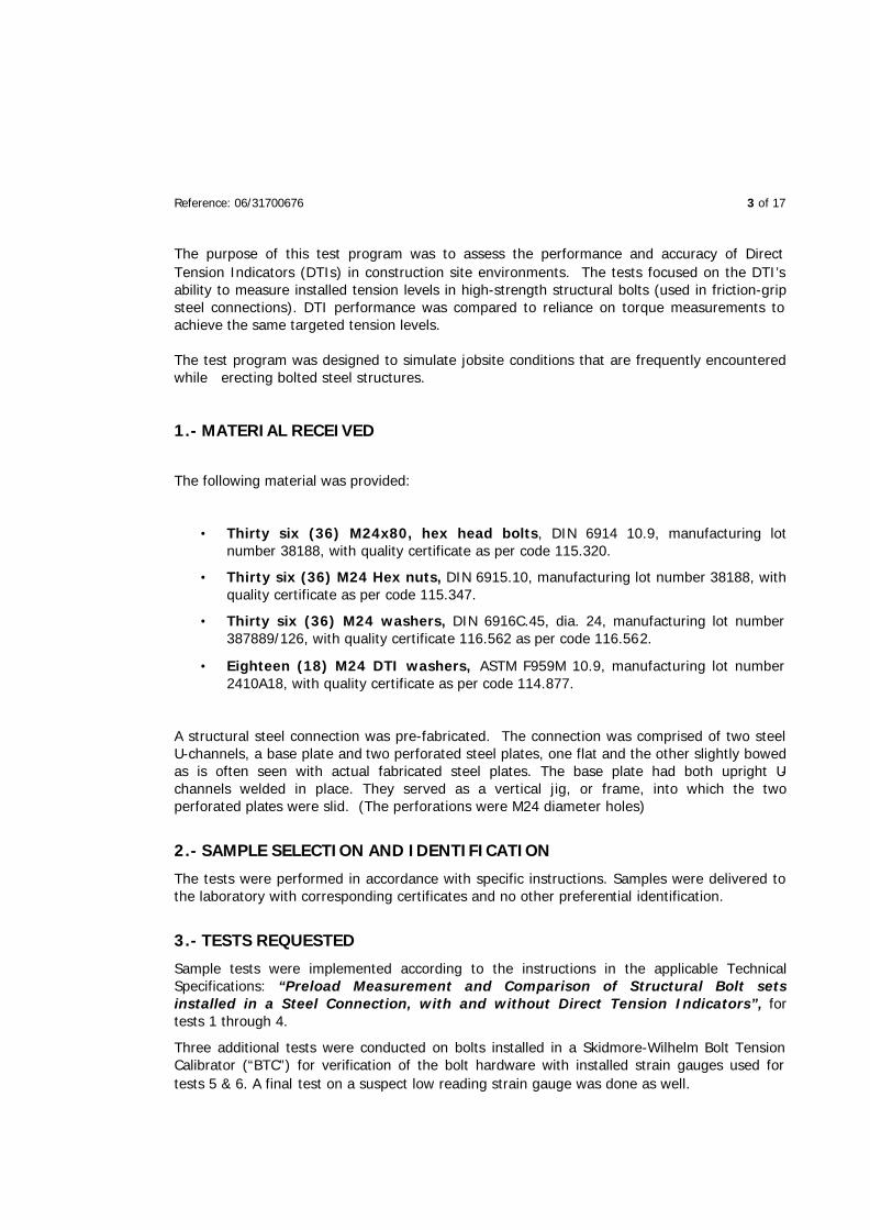
The purpose of this test program was to assess the performance and accuracy of Direct Tension Indicators (DTIs) in construction site environments. The tests focused on the DTI’s ability to measure installed tension levels in high-strength structural bolts (used in friction-grip steel connections). DTI performance was compared to reliance on torque measurements to achieve the same targeted tension levels.
The test program was designed to simulate jobsite conditions that are frequently encountered while erecting bolted steel structures.
1.- MATERIAL RECEIVED
The following material was provided:
• Thirty six (36) M24x80, hex head bolts, DIN 6914 10.9, manufacturing lot number 38188, with quality certificate as per code 115.320.
• Thirty six (36) M24 Hex nuts, DIN 6915.10, manufacturing lot number 38188, with quality certificate as per code 115.347.
• Thirty six (36) M24 washers, DIN 6916C.45, dia. 24, manufacturing lot number 387889/126, with quality certificate 116.562 as per code 116.562.
• Eighteen (18) M24 DTI washers, ASTM F959M 10.9, manufacturing lot number 2410A18, with quality certificate as per code 114.877.
A structural steel connection was pre-fabricated. The connection was comprised of two steel U-channels, a base plate and two perforated steel plates, one flat and the other slightly bowed as is often seen with actual fabricated steel plates. The base plate had both upright U-channels welded in place. They served as a vertical jig, or frame, into which the two perforated plates were slid. (The perforations were M24 diameter holes)
2.- SAMPLE SELECTION AND IDENTIFICATION
The tests were performed in accordance with specific instructions. Samples were delivered to the laboratory with corresponding certificates and no other preferential identification.
3.- TESTS REQUESTED
Sample tests were implemented according to the instructions in the applicable Technical Specifications: “Preload Measurement and Comparison of Structural Bolt sets installed in a Steel Connection, with and without Direct Tension Indicators”, for tests 1 through 4.
Three additional tests were conducted on bolts installed in a Skidmore-Wilhelm Bolt Tension Calibrator (“BTC”) for verification of the bolt hardware with installed strain gauges used for tests 5 & 6. A final test on a suspect low reading strain gauge was done as well.

Reference: 06/31700676 4 of 17
For each of Test numbers 1 & 2, nine (9) strain-gauged bolt assemblies were used.
For Test numbers 3 & 4, nine (9) strain-gauged bolts were used, and three (3) bolt assemblies without strain gauges.
For BTC tests 5 & 6, one strain-gauged bolt assembly per test was used. Test included DTIs for Test 5. No DTIs were used for test 6, or on the final strain gauged bolt tension check in the Skidmore-Wilhelm Bolt Tension Calibrator.
4.- SUMMARY OF TESTS
The types of tests, and the number of samples tested, simulate conditions found in actual job-site bolting of structural steel. The steel plates were fabricated to appropriate technical specifications for field assembly. Table 1 is a summary of the tests performed.
Table 1. Test Descriptions
Type of Test Number of
Bolts to Test
Differentiating Factors
Test 1 9 Use of DTI’s, two flat plates, lubricated bolt assemblies
Test 2 9 Use of DTI’s, flat plate against bent plate, lubricated bolt assemblies.
Test 3 9 + 3 No use of DTI’s, flat plate against bent plate, lubricated bolt assemblies. Tightening torque was determined in the “Skidmore Bolt Tension Calibrator”(BTC). Torque used was the average torque required to tension each of three bolts to 240kN.
Test 4 9 No use of DTI’s, flat plate against bent plate, dry bolt assemblies. Tightening torque used was average torque determined in BTC in test #3
Test 5 1 Use of DTI, lubricated bolt assembly, in “Bolt Tension Calibrator”
Test 6 1 No DTI, dry bolt assembly, in “Bolt Tension Calibrator”. Tightening by torque wrench, using torque value used in test #3 and #4

Reference: 06/31700676 5 of 17
Assemblies used for each of the 6 tests are indicated in Table 2.
Table 2. Assembly Details
Test Bolt Nut Washer DTI (new)
Strain Gauge
Plate
Test 1 9L 9L 9L 9 9 F
Test 2 9L 9L 9L 9 9 F+D
Test 3 9L+3L 9L+3L 18L+6L 0 9 F+D
Test 4 9S 9S 18S 0 9 F+D
Test 5 1L 1L 1L 1 1 FTC
Te
st
Test 6 1S 1S 2S 0 1 BTC F = Flat plate B = Bent plate L = Lubricated D = Dry BTC = Bolt Tension Calibrator
• Lubrication on bolts and nuts was done with following product: Castrol Stick-Wax lubricant
• Dry bolt assemblies were dried with: “Hagasen” degreaser (formulated with anionic tensoactives)
For the six test groups of this report, the bolt samples tested were identified with a numbering system corresponding to the snugging (pre-tightening) and tightening sequence used, as illustrated in drawings depicted in Figures 4,7,10, & 11. The objective for these tests was to, “Measure the installed preload (tension) in structural bolt sets installed in a steel connection, with and without Direct Tension Indicators”. This objective will henceforth be referred to as the “Technical Reference Specification”.
All tests were performed at the Applus CTC laboratory and were witnessed by Mrs. Cristina Hernandez of FATOR, Applus technical personnel, and Henry Eckfeldt of Ecktra International, Inc.
5.- TEST METHODS AND RESULTS
The thirty-six bolts received were submitted to a process whereby a 2 mm hole was drilled in the center of the bolt head, to a depth of 35 mm. After the hole was drilled, the bolts were degreased prior to installing the strain gauge leads in the holes. Strain gauge measuring instrumentation was used in order to acquire the bolt deformation data directly from each one of the bolts as they were being tensioned (tightened). With subsequent bolt deformation, and the mechanical properties of the bolt material, the uniaxial force was determined and, with the working cross section of the bolt, the corresponding loads induced in the bolts were calculated.
The strain gauge leads installed in the bolts were connected to ¼ bands of bridge KFG-3-120C120-11, 120 ohm resistance with 5cm of prewiring glued in the drilled holes with an adhesive (M-Bond AE-10 of Vishay with RTV 3145 protection) and wired to three conductors

Reference: 06/31700676 6 of 17
35mm
with nominal resistance control, and insulated according to certificate of conformity CC110614. Positioning of the strain gauge can be seen in Figure 1.
Figure 1. Drilled hole for strain gauge installation
Once the strain gauges were installed in the bolt heads, a procedure was followed to calibrate the measurement of the forces by means of uniaxial strain tests, below the elastic limits, for 20% of the strain gauged bolts (eight (8) samples). This test procedure was done on a Shimadzu No. 72980, 50 MT universal testing machine, with a calibration date of September, 2006.
Figure 2. shows the calibration curves obtained for the eight (8) strain-gauged bolts, (chosen at random). A minimum of four (4) levels of loading were used. Note that the differences found could be considered high, taking into account variances between bolts, the precision of holes drilled, and the attachment of the strain gauge leads. Based on this curve value, the transformations of deformation/force were applied to the remaining 28 bolts, on the assumption that this data would be similar on the rest of these bolts.
Figure 2. Calibration Curve
R2 = 0,9629
0
100
200
300
400
500
600
0 100 200 300 400 500 600
Esfuerzo real MPa
Esf
uer
zo c
alcu
lad
o M
Pa

Reference: 06/31700676 7 of 17
Once these values were obtained, then two (2) of the calibrated bolts were included in every test of nine bolts (2 calibrated, 7 not). The last two tests (tests 5 & 6) were both done using previously calibrated bolts.
In all the following tests, the aspects that are described are the ones that were deemed to be of the greatest interest, or that could explain in more detail the methodology indicated in the “Technical Reference Specification”.
It should be noted that the established minimum tension for these DIN 6914 10.9 bolts is a tension of 240 kN, and all bolt loads obtained in these tests should be compared to this minimum required clamp load.
5.1.- Test 1.
5.1.1.- Testing Method
Testing Date: December 5, 2006
The fabricated structural steel connection , provided by the petitioner, was next installed. It consisted of two steel plates held between two U-shaped vertical columns welded to a base plate. This base plate was clamped to a steel frame. This prevented the steel plates from rotating when bolts were tightened. See Figure 3
Figure 3. Assembly for Test 1
The bolt assemblies were installed as summarized in Table 2. and, according to the Technical Reference Specification, the pre-tightening (“snugging”) of the bolts was done using a torque wrench as the tightening wrench on the nut (turned element) and an ordinary hand wrench on the bolt head (static element). Snugging sequence is as per Figure 4.
Figure 4. Snugging sequence, Test 1
4 2 6
8 1 9
7 3 5

Reference: 06/31700676 8 of 17
Pre-tightening, or snugging, of the plies was considered accomplished when, by visual inspection, the protrusions on the DTI just began to flatten. As a reference, in every case the applied torque to achieve the “snug” condition never exceeded 780 Nm.
After pre-tightening, the bolts were further tightened (in the same sequence) until the 0.4mm feeler gauge gained admittance to a maximum of two spaces between the DTI protrusions.
Feeler gauges were previously calibrated in a 500-311 Mitutoyo 150mm electronic caliper, No. 31819, precise to 0.005mm. calibrated in November, 2006
Figure 5 is an example of a fully tightened connection. In this case sufficient torque was applied to bolt #1 (less than 1050Nm) so the 0.4mm feeler gauge would gain admittance in only one space between protrusions of the DTI. The strain gauge’s registered reading in bolt #1, along with the readings registered by the remaining strain gauges in the connection, was documented. From these registered values, the axial load induced in each bolt was calculated.
Figure 5. Tightening of bolt to 302 kN.
5.1.2.- Results.
Table 3 lists the uniaxial loads obtained and the number of feeler gauge admittances. As mentioned before, bolts are numbered according to tightening sequence.
It should be noted that on bolt #9, the strain gauge was rechecked in the “final test” due to an suspect low reading and was found to be reading low by 78 kN, compared to the load on the BTC, (see note on page 17). If the deviation were added to bolt #9’s recorded tension the bolt’s load would be 277 kN and within the range of the other recorded bolt loads.

Reference: 06/31700676 9 of 17
Table 3. Results of test 1.
Bolt
Load
[kN]
Feeler gauge
Admissions
0.4mm
Torque
[Nm]
1 302 1 1025-1050
2 322 0 1025-1050
3 233 0 1025-1050
4 280 2 1025-1050
5 249 0 1000-1025
6 282 2 1000-1025
7 287 1 1000-1025
8 260 0 1000-1025
9 199*pg.17 1 1000-1025
5.2.- Test 2.
5.2.1.- Testing Method
Testing Date: December 5, 2006
For this test one flat steel plate and one slightly curved plate were installed in the test jig used in test #1. The curved plate was placed curving away from the flat plate. Separation between plates at the top, with plates in firm contact at the bottom, was 11.8mm. Figure 6 shows the separation between the plates at the top.
Figure 6. Test #2 detail
Once all holes were concentric, the bolts were installed as summarized in Table 2. According to specifications, pre-tightening of the bolts was done using a torque wrench as the rotating tightening tool on the nut (turned element) and an ordinary hand wrench on the bolt head (static element). Pre tightening and tightening sequence was done as shown in Figure 7.

Reference: 06/31700676 10 of 17
Figure 7. Tightening sequence, Test #2.
Pre-tightening is considered accomplished when, by visual inspection, the DTI protrusions begin to slightly flatten, or deform. In every case the applied torque never exceeded 780 Nm.
Following pre-tightening, final tightening was done until the 0.4mm feeler gauge gained admittance in a maximum of two spaces between the flattened DTI protrusions.
Feeler gauges were previously calibrated in a 500-311 Mitutoyo 150mm electronic caliper, No. 31819, precise to 0.005mm, calibrated in November, 2006
5.2.2.- Results.
Table 4 below summarizes the results of the uniaxial forces obtained and the number of feeler gauge admittances. As mentioned before, bolts are numbered according to the tightening sequence
Table 4. Results of Test 2
Bolt
Load
[kN]
Feeler gauge
Admissions
0.4mm
Torque
[Nm]
1 246 1 1050-1100
2 300 1 1025-1050
3 273 0 1025-1050
4 299 2 1025-1050
5 282 0 1050-1100
6 283 0 1050-1100
7 295 1 1050-1100
8 294 2 1050-1100
9 268 1 1050-1100
8 4 6
2 1 3
7 5 9

Reference: 06/31700676 11 of 17
Complementary information. Following are presented the variations in loads in each of the bolts and the bolt tightening sequence. In Figure 8 one can observe that, once the tension level has been reached at the point at which the maximum admittance of feeler gauges is reached, there isn’t an appreciable variation, in spite of the variation of the clamp force between plates, due to the sequential tightening of the remaining bolts.
5.3.- Test 3.
5.3.1.- Testing Method
Testing Date: December 5, 2006
In this test three (3) lubricated bolts assemblies without strain gauges were installed as indicated in table 2 in the Skidmore-Wilhelm “Bolt Tension Calibrator” (BTC), model M, No. 9075. This BTC was calibrated in November of 2006, according to calibration certificate TLL001-06-11-33010-1. Figure 9 shows the installation.
Figure 9. Assembly for Test 3
Figure 8. Clamp force variations during Tightening, Test #2
Variacion fuerza durante el apriete
0
50
100
150
200
250
300
350
0 2 4 6 8 10
Secuencia de apriete
Car
ga
(kN
)
Carga pretensado torn i l lo 1 [KN]
246 245 244 243 242 242 241 241 257
Clamp force variations during tightening
Bolt Tightening Sequence
Pre tightening (snugging) loads, bolt #1 [kN]

Reference: 06/31700676 12 of 17
Once each bolt assembly was installed (bolt & hardened washer on gauge side, nut and hardened washer on back plate), tightening was done with the torque wrench on the nut (rotated element) and an ordinary hand wrench on the bolt head (static element). Tightening continued until the 240 kN (54 kips) clamp load was reached (indicated on the BTC dial) and the torque value to reach 240 kN was registered. This procedure was repeated with two more bolts from the same lot number (total of 3 bolts). The mean torque applied to obtain 240 kN in each of the three bolts was 945 kN. This torque value was then used to install strain gauged bolt assemblies in the steel plates in Test #3 as well as in Test #4.
Bolt installation in the plates was done as per conditions summarized in Table 2. Lubricated strain-gauged bolt assemblies were installed without DTIs. The flat plate and the bent plate were used. Pre-tightening (snugging) followed by tightening was done with an ordinary hand wrench used to keep the bolt head from rotating. A torque wrench was used to rotate the nut. The snugging / tightening sequence is illustrated in the following drawing.
Figure 10. Tightening Sequence, Test #3
Although pre-tightening torque never exceeded 780 Nm, It should be noted that a “bedding or snugging” torque (of near 780 kN for these bolts) is not usually applied, or even noted in the field. In practice, bedding the plies is done with the full effort of an installer using a spanner or ordinary hand wrench. It is believed that the higher torque in the snugging method used in these tests could be characterized as additional practice.
Following pre-tightening, the torque value was increased to 945 Nm, and the resulting bolt loads were noted.
8 4 6
2 1 3
7 5 9

Reference: 06/31700676 13 of 17
5.3.2.- Results.
Table 5 below documents the results of uniaxial force obtained. As mentioned before the bolts are numbered according to the tightening sequence
Table 5. Results of Test 3
Bolt
Load
[kN]
Torque
[Nm]
1 229 945
2 234 945
3 251 945
4 289 945
5 238 945
6 289 945
7 262 945
8 254 945
9 248 945
5.4.- Test 4.
5.4.1.- Testing Method
Testing Date: December 5, 2006
This test was done according to the reference specifications. Final tightening was done using the 945 Nm torque value obtained in Test #3. Specifically, the installation of the bolts was done as indicated in Table 2. Dry bolt assemblies (not lubricated assemblies) were used without DTIs. One flat and one bent plate were used. A pre-tightening was done using a torque wrench on the nut and an ordinary hand wrench to hold the bolt head. Tightening sequence was as shown below.
Figure 11. Tightening sequence, Test #4
8 4 6
2 1 3
7 5 9

Reference: 06/31700676 14 of 17
Pre-tightening torque never exceeded 780 Nm. Again, It should be noted that a “bedding or snugging” torque (of near 780 kN for these bolts) is not usually applied, or even noted in the field. In practice, bedding the plies is done with the full effort of an installer using a spanner or ordinary hand wrench. It is believed that the higher torque in the snugging method used, in these tests, could be characterized as improved practice.
Tightening was done until 945 Nm was reached on the torque wrench.
5.4.2.- Results.
Table 6 summarizes the results of uniaxial force obtained. As before, bolts are numbered according to their tightening sequence.
Table 6. Results of Test 4
Bolt
Load
[kN]
Torque
[Nm]
1 167 945
2 103 945
3 140 945
4 199 945
5 139 945
6 152 945
7 147 945
8 167 945
9 192 945

Reference: 06/31700676 15 of 17
5.5.- Test 5 & 6.
5.5.1.- Testing Method
Testing Date: December 12, 2006
Tests were carried out, as requested, using only the Skidmore-Wilhelm “Bolt Tension Calibrator” on bolts in conditions as summarized in Table 2. Test #5 was done using a lubricated bolt assembly with a calibrated strain gauge and a DTI. Test #6 was done on a dry bolt assembly with a calibrated strain gauge with no DTI. Figure 13 shows the test equipment.
Figure 12. Test equipment for Test #5
For test 5 a lubricated bolt assembly with DTI and strain gauge was installed and, in accordance with instructions, the gauge on the calibrator was covered. Pre-tightening was done by visual inspection of the protrusions, as was done in tests #1 & #2 (slight flattening). Following this, the nut was turned until DTI protrusions rejected the 0.4mm feeler gauge in all but two spaces between protrusions. The cover on the gauge was removed and the tension indicated was noted.
In test #6 the gauge was again covered. A dry strain-gauged bolt assembly without DTI was installed. Pre-tightening was done with ordinary hand wrenches, just as is done at a job site: the full effort of an installer using a hand wrench or spanner. After this, torque was applied as in test #3. In other words, until 945 Nm was registered on the torque wrench. The cover on the gauge was removed and the tension indicated was noted.

Reference: 06/31700676 16 of 17
5.5.2.- Results.
Table 7 below lists the results of uniaxial force obtained.
Table 7. Results of Tests 5 & 6
Test
Load BTC
[kip/kN]
Bolt Load
[kN]
Feeler gauge
Admissions
0.4mm
Torque
[Nm]
5 Pre tightening 42/187 182 - -
5 62,5/278 260 1 -
6 Pre tightening 22/98 96 - -
6 45/200 202 - 945
6.- CONCLUSIONS
Figure 13 depicts graphs of bolt behaviour in tests 1 through 4.
Figure 13. Variations in bolt behaviour from tests 1-4
There exists some variations in monitored bolt tension readings in each test and these can be attributed to: production differences from bolt to bolt, differences in the nuts, the accuracy and consistency of installation of the strain gauges, the adhesion of the strain gauge wires in the bolt head, the fact that only 20% of the strain gauged bolts (picked at random) were calibrated, and the dimensional variability of the plates and holes. Having said this, these variations are more accentuated in cases where DTIs are not utilized, such as in tests 3 & 4. In tests 1 & 2, considering that the deformation of the bent plate requires higher bedding torque and values of tension, this objective was easily accomplished by the partial compressing of the DTIs in the initial snug tightening procedure.
12
34
56
7
8
9
0
50
100
150
200
250
300
350
kN
Tornillo
Ensayoensayo 1 ensayo 2 ensayo 3 ensayo 4
bolt
test test test test

Reference: 06/31700676 17 of 17
When taking into account the later discovered low reading of the bolt with the defective strain gauge (results of Test #1, Bolt #9) all bolts tightened using the Direct Tension Indicating washers showed loads appreciably higher than the required minimum load.
In Tests #3 and #4, it remains in evidence that the variability of the values of tension show a marked descent, while in Test #1, only the one bolt (on which the low reading strain gauge had been installed) fell short of the required tension (240kN). In test #2, all the bolts reached the minimum required tension. In test #3 there are 3 bolts that don’t reach the minimum value of tension, and this cannot be attributed to factors related to the variations of the strain gauges.
In the case of the dry bolts in test #4; dryness being a minimal condition of degradation, there is a performance level vastly inferior to the rest of the tests performed. The required tension levels were not reached in any of the cases, even though the prescribed torque of 945 Nm was applied to all dry bolts. (Dryness and corrosion inevitably occur in construction site environments). This is to be expected since the coefficient of friction in bolt assemblies has extreme variations (usually increasing) when bolt assembly surfaces are exposed to environmental conditions at job sites.
Finally, tests 5 & 6 confirm the reliability of the results obtained directly on bolts tested with the BTC. Also confirmed are the significant drops in tensions obtained in dry or otherwise degraded bolts.
7.- OBSERVATIONS
To limit the level of dispersion and to eliminate variability due to test method factors, it is recommended, in future, that all strain gauged bolts be calibrated prior to testing, and not just a representative sample.
Antoni Solà i Lorente
Director
A+ Certification Technological Center
Mónica Hitscherich
Technical Manager
A+ Certification Technological Center
ENGLISH TRANSLATION. ORIGINAL TEXT IN SPANISH
In case of discrepancies between the English and the Spanish versions, the Spanish version shall prevail over the English one.