Embed Size (px)
Citation preview
Premise
Installation
Guide
T a b l e O f C o n t e n t s
Overview of Cabling Standards ........................................................................1-2
Horizontal Cabling System Structure ...............................................................3-5
Work Area ............................................................................................................ 6
Horizontal Distances of Copper Links (Open Office) ............................................ 7
Twisted Pair (Balanced) Cabling ......................................................................... 8
Horizontal UTP Cable ........................................................................................... 8
UTP Patch Cords & Cross-Connect Jumpers ....................................................... 9
TIA/EIA 568 B.1 ............................................................................................10-11
TIA/EIA 568 B.2 ................................................................................................. 12
TIA/EIA 568 B.3 ............................................................................................12-13
Straight-Through or Reversed ........................................................................... 14
How to Read a Modular Cord............................................................................. 14
Common Outlet Configurations ....................................................................14-15
GenSPEED ® 10 MTP™ Installation Instructions ................................................ 16
Wire Color Codes ..........................................................................................17-18
Application-Specific Pair Assignments ............................................................. 19
Recommended Cabling Practices .................................................................20-21
UTP Connector Terminations ............................................................................. 21
NEC Fire Resistance Levels ............................................................................... 22
NEC Substitution Chart ..................................................................................... 23
Industry Standards, Typical Uses & Electrical Requirements .......................24-25
Notes ............................................................................................................27-28
This easy-to-follow reference guide is designed to assist you in installing, terminating and testing category unshielded twisted pair (UTP) cables to maximize their performance and ensure they meet or exceed ANSI/TIA/EIA 568 B standards.
T a b l e O f C o n t e n t s
1
ANSI/TIA/EIA 568 BANSI/TIA/EIA 568 B ('568 B) replaced ANSI/TIA/EIA 568 A as the “Commercial Building Telecommunications Cabling Standard” in May 2001. All addenda of 568 A and all TSBs (67, 72, 75 and 95) have been incorporated into the new standard.
The 568 B document is broken into three sections:
B.1 - General RequirementsB.2 - Balanced Twisted Pair Cabling ComponentsB.3 - Optical Fiber Cabling Components Standards
For clarity and consistency, '568 B based terminology is used in the following overview.
Purpose• Tospecifyagenericvoiceanddatatelecommunicationscablingsystem
that will support a multi-product, multi-vendor environment.
• Toprovidedirectionforthedesignoftelecommunicationsequipment and cabling products intended to serve commercial enterprises.
• Toenabletheplanningandinstallationofastructuredcablingsystem for commercial buildings that is capable of supporting the diverse telecommunications needs of building occupants.
• Toestablishperformanceandtechnicalcriteriaforvarioustypesof cable and connecting hardware, and cabling system design and installation.
O v e r v i e w o f C a b l i n g S t a n d a r d s

2
Scope• Specificationsareintendedfortelecommunicationsinstallations
that are “office oriented.”
• Requirementsareforastructuredcablingsystemwithausablelife in excess of 10 years.
• Specificationsaddressed: - Recognized Media - Cable and Connecting Hardware - Performance - Topology - Cabling Distance - Installation Practices - User Interfaces - Channel Performance
Cabling Elements• HorizontalCabling:
- Horizontal Cross-Connect (HC) - Horizontal Cable - Consolidation Point (CP) (optional) - Transition Point (TP) (optional) - Telecommunications Outlet/Connector (TO)
• BackboneCabling: - Main Cross-Connect (MC) - Interbuilding Backbone Cable - Intermediate Cross-Connect (IC) - Intrabuilding Backbone Cable
• WorkArea(WA)• TelecommunicationsRoom(TR)• EquipmentRoom(ER)• EntranceFacility(EF)• Administration
O v e r v i e w o f C a b l i n g S t a n d a r d s
O v e r v i e w o f C a b l i n g S t a n d a r d s
3
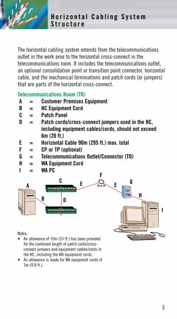
The horizontal cabling system extends from the telecommunications outlet in the work area to the horizontal cross-connect in the telecommunications room. It includes the telecommunications outlet, an optional consolidation point or transition point connector, horizontal cable, and the mechanical terminations and patch cords (or jumpers) that are parts of the horizontal cross-connect.
Telecommunications Room (TR)A = Customer Premises EquipmentB = HC Equipment CordC = Patch PanelD = Patch cords/cross-connect jumpers used in the HC,
including equipment cables/cords, should not exceed 6m (20 ft.)
E = Horizontal Cable 90m (295 ft.) max. totalF = CP or TP (optional)G = Telecommunications Outlet/Connector (TO)H = WA Equipment CordI = WA PC
A
B D
EF
C GE
H
I
H o r i z o n t a l C a b l i n g S y s t e m S t r u c t u r e
Notes:• Anallowanceof10m(33ft.)hasbeenprovided
for the combined length of patch cords/cross-connect jumpers and equipment cables/cords in the HC, including the WA equipment cords.
• AnallowanceismadeforWAequipmentcordsof3m (9.8 ft.).

4
Work Area (WA)Some points specified for the horizontal cabling subsystem include:• RecognizedHorizontalCables:
•4-pair100 unshielded twisted pair (UTP), screened twisted pair (ScTP) or Mosaic Twisted Pair (MTP) •2-fiber(duplex)62.5/125µm or50/125µm
• Multi-pairandmulti-unitcablesareallowed,providedthattheysatisfy the hybrid and bundled cable requirements of TIA/EIA 568 B.2.
• Groundingmustconformtoapplicablebuildingcodes,aswellasANSI/TIA/EIA 607.
• Aminimumoftwotelecommunicationsoutletsarerequiredforeach individual work area per TIA/EIA 568 B.1. First outlet: 100 Category 3 twisted pair (Category 5e is recommended). Second outlet: 100 Category 5e twisted pair (Category 6 is recommended) or two-fiber multi-mode optical fiber, either 62.5/125µmor50/125µm.
• Onetransitionpoint(TP)isallowedbetweendifferentformsofthesame cable type (e.g., where undercarpet cable connects to round cable).
• 50 coax and 150 STP-A cabling are not recommended for new installations.
• Additionaloutletsmaybeprovided.Theseoutletsareinadditiontoand may not replace the minimum requirements of the standard.
• Bridgedtapsandsplicesarenotallowedforcopper-basedhorizontal cabling (splices are allowed for fiber).
• Application-specificcomponentsshallnotbeinstalledaspartofthe horizontal cabling. When needed, they must be placed external to the telecommunications outlet or horizontal cross-connect (e.g., splitters, baluns).
• Theproximityofhorizontalcablingtosourcesofelectromagneticinterference (EMI) shall be taken into account.
H o r i z o n t a l C a b l i n g S y s t e m S t r u c t u r e
H o r i z o n t a l C a b l i n g S y s t e m S t r u c t u r e
5
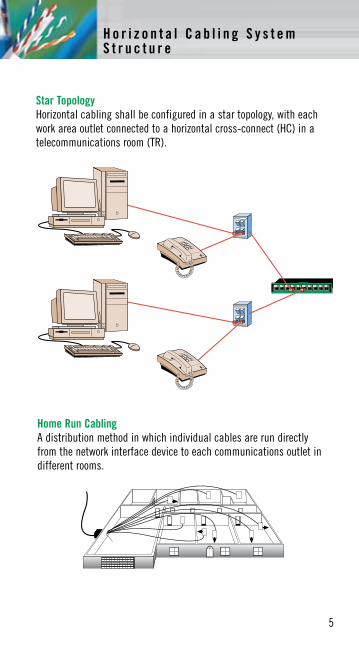
Star TopologyHorizontal cabling shall be configured in a star topology, with each work area outlet connected to a horizontal cross-connect (HC) in a telecommunications room (TR).
Home Run CablingA distribution method in which individual cables are run directly from the network interface device to each communications outlet in different rooms.
5
H o r i z o n t a l C a b l i n g S y s t e m S t r u c t u r e
6
Some specifications related to work area cabling:• Equipmentcordsareassumedtohavethesameperformanceas
patch cords of the same type and category.
• Whenused,adaptersareassumedtobecompatiblewiththetransmission capabilities of the equipment to which they connect.
• Horizontalcablelengthsarespecifiedwiththeassumptionthatamaximum cable length of 3m (10 ft.) is used for equipment cords in the work area.
Note: For establishing maximum horizontal channel distances, a combined maximum length of 10m (33 ft.) is allowed for patch cables (or jumpers) and equipment cables in the work area and the telecommunications room.
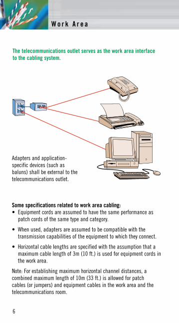
Adapters and application-specific devices (such as baluns) shall be external to the telecommunications outlet.
The telecommunications outlet serves as the work area interface to the cabling system.
W o r k A r e a

W o r k A r e a
7
Table 1 - Maximum Length of Work Area Cables
Maximum Combined Maximum Length of Work Area Length of Length of Work Cables, Patch Cords Horizontal Cable Area Cable and Equipment Cable
H W C m (ft.) m (ft.) m (ft.)
90 (295) 5 (16) 10 (33)
85 (279) 9 (30) 14 (46)
80 (262) 13 (44) 18 (59)
75 (246) 17 (57) 22 (72)
70 (230) 22 (71) 27 (89)
Copper work area cables connected to a MuTOA (Multi-user Telecommunications Outlet Assembly) shall meet the requirements of '568 B.1. The maximum length of copper work area cables shall be determined according to:
C=(102-H)/1.2 W=C-5(<20m)
Where: C is the combined length of the work area cable, equipment cable and patch cord (m). W is the length of the work area cable (m). H is the length of the horizontal cable (m).
The above equations assume that there is a total of 5m (16 ft.) of patch and equipment cables in the telecommunications room. Table 1 shows the application of these formulas. The length of work area cables shall not exceed 20m (66 ft.). The MuTOA shall be marked with the maximum allowable work area cable length.
H o r i z o n t a l D i s t a n c e s o f C o p p e r L i n k s ( O p e n O f f i c e )
8
The three categories of transmission performance specified by TIA 568 B.2 for cables, connecting hardware, link and channel are:Category 3Transmission characteristics are specified up to 16 MHzTypical Applications10 BASE-T, 4 Mbps Token Ring, 52 Mbps ATM, 100VG-ANYLAN
Category 5eTransmission characteristics are specified up to 100 MHzTypical Applications1000 BASE-T (Gigabit Ethernet), 100 BASE-TX, 16 Mbps Token Ring, 155 Mbps ATM
Category 6Transmission characteristics up to 250 MHzTypical ApplicationsGigabit Ethernet and 10 Gigabit Ethernet (limited distance)
Category 6ATransmission characteristics up to 500 MHzTypical Applications10G BASE-T, 155 Mbps ATM, IEEE 802.3af for PoE
• Solid4-pair24AWG(0.51mm)specified,22AWG(0.64mm)solidalso allowed. An overall shield (ScTP) is optional.
• Performancemarkingshouldbeprovidedtoshowtheapplicableperformance category. These markings do not replace safety markings.
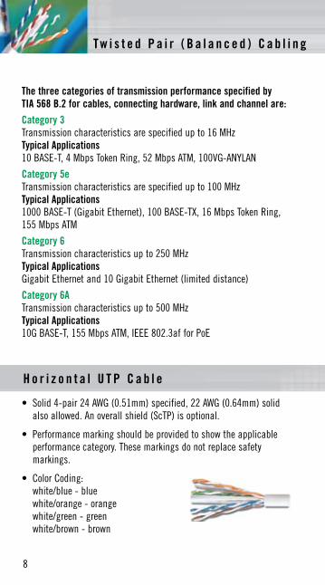
• ColorCoding: white/blue - blue white/orange - orange white/green - green white/brown - brown
H o r i z o n t a l U T P C a b l e
T w i s t e d P a i r ( B a l a n c e d ) C a b l i n g
T w i s t e d P a i r ( B a l a n c e d ) C a b l i n g
9
• Patchcordsshouldusestrandedconductorsforadequateflexlife.
• Patchcordsmustmeettheminimumperformancerequirementsforhorizontal cable except that 20 percent more attenuation is allowed by TIA/EIA 568 B.2.
• Performancemarkingsshouldbeprovidedtoshowtheapplicabletransmission category in addition to safety markings.
• InsulatedO.D.ofstrandedwiresshouldbe0.8mm(0.032in.)to1mm (0.039 in.) to fit into a modular plug.
• ColorCodesforStranded,100 UTP Patch Cord: white/blue - blue PAIR 1 white/orange - orange PAIR 2 white/green - green PAIR 3 white/brown - brown PAIR 4
• Colorcodeforcross-connectjumpers:oneconductorwhite,theother a visibly distinct color such as red or blue.
Note: Because of their identical pair groupings, patch cords terminated with either T568A
or T568 B pair assignments may be used interchangeably, provided that both ends
are terminated with the same pin/pair scheme.
U T P P a t c h C o r d s & C r o s s - C o n n e c t J u m p e r s
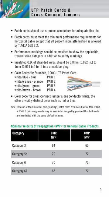
Category CMR CMP NVP NVP
Category 3 64 65
Category 5e 70 72
Category 6 70 72
Category 6A 68 72
Nominal Velocity of Propagation (NVP) for General Cable Products
10
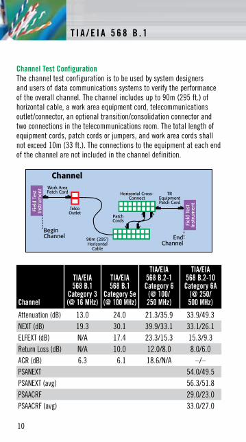
Channel Test ConfigurationThe channel test configuration is to be used by system designers and users of data communications systems to verify the performance of the overall channel. The channel includes up to 90m (295 ft.) of horizontal cable, a work area equipment cord, telecommunications outlet/connector, an optional transition/consolidation connector and two connections in the telecommunications room. The total length of equipment cords, patch cords or jumpers, and work area cords shall not exceed 10m (33 ft.). The connections to the equipment at each end of the channel are not included in the channel definition.
T I A / E I A 5 6 8 B . 1
Channel
TIA/EIA 568 B.1
Category 3 (@ 16 MHz)
TIA/EIA 568 B.1
Category 5e (@ 100 MHz)
TIA/EIA 568 B.2-1
Category 6 (@ 100/ 250 MHz)
TIA/EIA 568 B.2-10
Category 6A (@ 250/ 500 MHz)
Attenuation (dB) 13.0 24.0 21.3/35.9 33.9/49.3NEXT (dB) 19.3 30.1 39.9/33.1 33.1/26.1ELFEXT (dB) N/A 17.4 23.3/15.3 15.3/9.3Return Loss (dB) N/A 10.0 12.0/8.0 8.0/6.0ACR (dB) 6.3 6.1 18.6/N/A –/–PSANEXT 54.0/49.5PSANEXT (avg) 56.3/51.8PSAACRF 29.0/23.0PSAACRF (avg) 33.0/27.0
T I A / E I A 5 6 8 B . 1
11
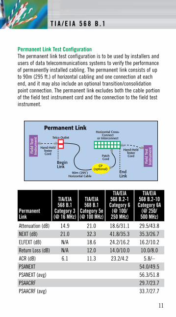
Permanent Link Test ConfigurationThe permanent link test configuration is to be used by installers and users of data telecommunications systems to verify the performance of permanently installed cabling. The permanent link consists of up to 90m (295 ft.) of horizontal cabling and one connection at each end, and it may also include an optional transition/consolidation point connection. The permanent link excludes both the cable portion of the field test instrument cord and the connection to the field test instrument.
T I A / E I A 5 6 8 B . 1
Permanent Link
TIA/EIA 568 B.1
Category 3 (@ 16 MHz)
TIA/EIA 568 B.1
Category 5e (@ 100 MHz)
TIA/EIA 568 B.2-1
Category 6 (@ 100/ 250 MHz)
TIA/EIA 568 B.2-10
Category 6A (@ 250/ 500 MHz)
Attenuation (dB) 14.9 21.0 18.6/31.1 29.5/43.8NEXT (dB) 21.0 32.3 41.8/35.3 35.3/26.7ELFEXT (dB) N/A 18.6 24.2/16.2 16.2/10.2Return Loss (dB) N/A 12.0 14.0/10.0 10.0/8.0ACR (dB) 6.1 11.3 23.2/4.2 5.8/–PSANEXT 54.0/49.5PSANEXT (avg) 56.3/51.8PSAACRF 29.7/23.7PSAACRF (avg) 33.7/27.7
12
The transmission performance of a cabling system depends upon the characteristics of the horizontal cable, connecting hardware, patch cords, equipment cords, work area cords, cross-connect wiring, the total number of connections, and the care with which they are installed and maintained. The development of high-speed applications requires that cabling systems be characterized by transmission parameters such as insertion loss, PSNEXT loss, return loss, and PSELFEXT. Category 6A cables include the additional transmission parameters PSANEXT and PSAACRF. System designers use these performance criteria to develop applications that utilize all four pairs in a cabling system for simultaneous bi-directional transmission. This standard provides minimum cabling component performance criteria as well as procedures for component and cabling performance validation. This standard also specifies field test instruments and applicable reference measurement procedures for all transmission parameters.
This standard specifies minimum requirements for balanced twisted-pair telecommunications cabling components that are used up to and including the telecommunications outlet/connector and between buildings in a campus environment. This standard specifies the minimum performance requirements for recognized balanced twisted-pair cabling components as described in ANSI/TIA/EIA 568 B.1 (i.e., cable, connectors, connecting hardware, patch cords, equipment cords, work area cords and jumpers) and for the field test equipment used to verify the performance of these components as installed.
Optical Fiber Cabling ComponentsThis standard contains the performance specifications for the optical fiber cables recognized in premises cabling standards. Cable transmission performance for the outside plant telecommunications cable shall comply with ANSI/ICEA S 87-640. Inside plant optical fiber telecommunications cable shall comply with ANSI/ICEA S 83-596. Each cabled fiber shall meet the graded performance specifications of the table to the right.
T I A / E I A 5 6 8 B . 2
T I A / E I A 5 6 8 B . 3
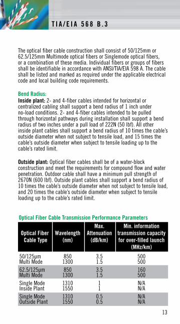
The optical fiber cable construction shall consist of 50/125mm or 62.5/125mm Multimode optical fibers or Singlemode optical fibers, or a combination of these media. Individual fibers or groups of fibers shall be identifiable in accordance with ANSI/TIA/EIA 598 A. The cable shall be listed and marked as required under the applicable electrical code and local building code requirements.
Bend Radius:Inside plant: 2- and 4-fiber cables intended for horizontal or centralized cabling shall support a bend radius of 1 inch under no-load conditions. 2- and 4-fiber cables intended to be pulled through horizontal pathways during installation shall support a bend radius of two inches under a pull load of 222N (50 lbf). All other inside plant cables shall support a bend radius of 10 times the cable’s outside diameter when not subject to tensile load, and 15 times the cable’s outside diameter when subject to tensile loading up to the cable’s rated limit.
Outside plant: Optical fiber cables shall be of a water-block construction and meet the requirements for compound flow and water penetration. Outdoor cable shall have a minimum pull strength of 2670N (600 lbf). Outside plant cables shall support a bend radius of 10 times the cable’s outside diameter when not subject to tensile load, and 20 times the cable’s outside diameter when subject to tensile loading up to the cable’s rated limit.
13
Max. Min. information Optical Fiber Wavelength Attenuation transmission capacity Cable Type (nm) (dB/km) for over-filled launch (MHz/km)
50/125µm 850 3.5 500 Multi Mode 1300 1.5 50062.5/125µm 850 3.5 160 Multi Mode 1300 1.5 500Single Mode 1310 1 N/A Inside Plant 1550 1 N/ASingle Mode 1310 0.5 N/A Outside Plant 1550 0.5 N/A
Optical Fiber Cable Transmission Performance Parameters
T I A / E I A 5 6 8 B . 3
14
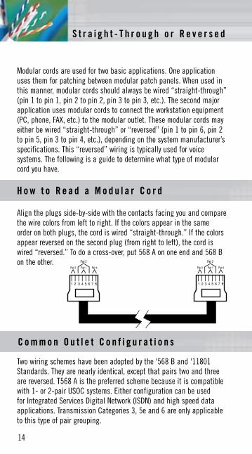
Modular cords are used for two basic applications. One application uses them for patching between modular patch panels. When used in this manner, modular cords should always be wired “straight-through” (pin 1 to pin 1, pin 2 to pin 2, pin 3 to pin 3, etc.). The second major application uses modular cords to connect the workstation equipment (PC, phone, FAX, etc.) to the modular outlet. These modular cords may either be wired “straight-through” or “reversed” (pin 1 to pin 6, pin 2 to pin 5, pin 3 to pin 4, etc.), depending on the system manufacturer’s specifications. This “reversed” wiring is typically used for voice systems. The following is a guide to determine what type of modular cord you have.
Align the plugs side-by-side with the contacts facing you and compare the wire colors from left to right. If the colors appear in the same order on both plugs, the cord is wired “straight-through.” If the colors appear reversed on the second plug (from right to left), the cord is wired “reversed.” To do a cross-over, put 568 A on one end and 568 B on the other.
H o w t o R e a d a M o d u l a r C o r d
Two wiring schemes have been adopted by the '568 B and '11801 Standards. They are nearly identical, except that pairs two and three are reversed. T568 A is the preferred scheme because it is compatible with 1- or 2-pair USOC systems. Either configuration can be used for Integrated Services Digital Network (ISDN) and high speed data applications. Transmission Categories 3, 5e and 6 are only applicable to this type of pair grouping.
C o m m o n O u t l e t C o n f i g u r a t i o n s
S t r a i g h t - T h r o u g h o r R e v e r s e d
1 2 3 4 5 6 7 8 1 2 3 4 5 6 7 8
Pair 3 Pair 1 Pair 4
Pair 2
Pair 3 Pair 1 Pair 4
Pair 2
S t r a i g h t - T h r o u g h o r R e v e r s e d
15
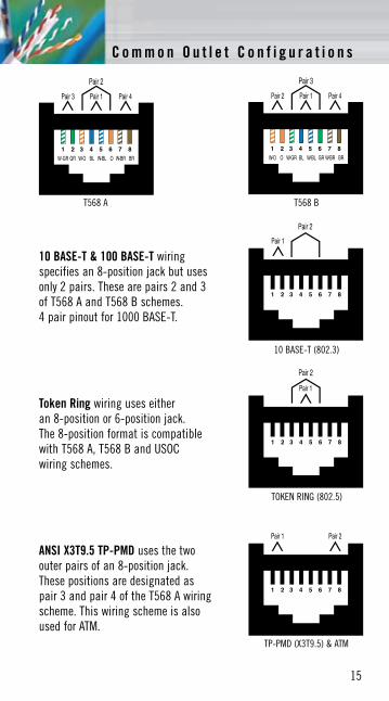
10 BASE-T & 100 BASE-T wiring specifies an 8-position jack but uses only 2 pairs. These are pairs 2 and 3 of T568 A and T568 B schemes. 4 pair pinout for 1000 BASE-T.
C o m m o n O u t l e t C o n f i g u r a t i o n s
Token Ring wiring uses either an 8-position or 6-position jack. The 8-position format is compatible with T568 A, T568 B and USOC wiring schemes.
ANSI X3T9.5 TP-PMD uses the two outer pairs of an 8-position jack. These positions are designated as pair 3 and pair 4 of the T568 A wiring scheme. This wiring scheme is also used for ATM.
T568 A T568 B
10 BASE-T (802.3)
TOKEN RING (802.5)
TP-PMD (X3T9.5) & ATM
16
G e n S P E E D ® 1 0 M T P™ I n s t a l l a t i o n I n s t r u c t i o n s
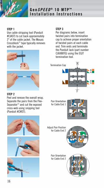
STEP 1 Use cable-stripping tool (Panduit #CJAST) to cut back approximately 2" of the cable jacket. The Mosaic Crossblock™ tape typically removes with the jacket.
STEP 2 Peel and remove the overall wrap. Separate the pairs from the Flex-Separator™ and cut the exposed cross-web using snipping tool (Panduit #CWST).
STEP 3 Per diagrams below, insert twisted pairs into termination cap to achieve proper orientation of twisted pairs at each cable end. Trim ends and terminate the Panduit Jack (part number CJ6X88TG) using the EGJT termination tool.
Termination Cap
Adjust Pair Position for Cable End 2
Pair Orientation for Cable End 1
Pair Orientation for Cable End 2

17
G e n S P E E D ® 1 0 M T P™ I n s t a l l a t i o n I n s t r u c t i o n s W i r e C o l o r C o d e s
Category 5e Cables A. Band-StripedTwisted Pair Wire
B. Solid-ColorNon-Twisted Wire
C. Quad Wire*,Solid-Color, Non-Twisted Wire
Standard 4-Pair Wiring Color Codes
PAIR 1 T White/Blue R BluePAIR 2 T White/Orange R OrangePAIR 3 T White/Green R GreenPAIR 4 T White/Brown R Brown
Note: White band-stripe on ring conductor is optional. For 6-wire jacks, use pair 1, 2 and 3 color codes. For 4-wire jacks, use pair 1 and 2 color codes.
*CAUTIONQuad wire is no longer acceptable for installation in multi-line environments. If encountered during a retrofit, quad wire should be replaced with 100 UTP if possible. Connecting new quad to installed quad will only amplify existing problems and limitations associated with quad wire. Leaving existing quad in place and connecting 100 UTP to it may also be ineffective, as the quad wire may negate the desired effect of the UTP.
18
W i r e C o l o r C o d e s
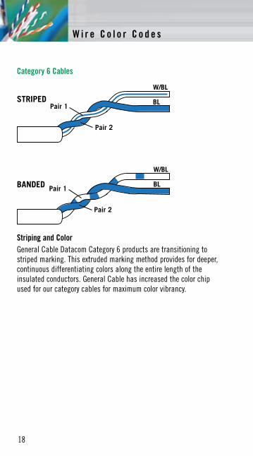
Striping and ColorGeneral Cable Datacom Category 6 products are transitioning to striped marking. This extruded marking method provides for deeper, continuous differentiating colors along the entire length of the insulated conductors. General Cable has increased the color chip used for our category cables for maximum color vibrancy.
Category 6 Cables
Pair 1
Pair 2
W/BL
BL
Pair 1
Pair 2
W/BL
BLBANDED
STRIPED
W i r e C o l o r C o d e s
19
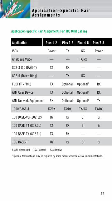
Application-Specific Pair Assignments For 100 OHM Cabling
Application Pins 1-2 Pins 3-6 Pins 4-5 Pins 7-8
ISDN Power TX RX Power
Analogue Voice — — TX/RX —
802-3 (10 BASE-T) TX RX — —
802-5 (Token Ring) — TX RX —
FDDI (TP-PMD) TX Optional1 Optional1 RX
ATM User Device TX Optional1 Optional1 RX
ATM Network Equipment RX Optional1 Optional1 TX
1000 BASE-T TX/RX TX/RX TX/RX TX/RX
100 BASE-VG (802.12) Bi Bi Bi Bi
100 BASE-T4 (802.3u) TX RX Bi Bi
100 BASE-TX (802.3u) TX RX — —
10G BASE-T Bi Bi Bi Bi
Bi=Bi-directional TX=Transmit RX=Receive
1Optional terminations may be required by some manufacturers’ active implementations.
A p p l i c a t i o n - S p e c i f i c P a i r A s s i g n m e n t s
20
Do:• Doterminateeachhorizontalcableonadedicated
telecommunications outlet.• Dolocatethemaincross-connectnearthecenterofthebuilding
to limit cable distances.• Domaintainthetwistofhorizontalandbackbonecablepairsup
to the point of termination.• Dotieanddresshorizontalcablesneatly.• Toavoidstretching,pullingtensionshouldnotexceed110N
(25 lbf) for 4-pair cables.• Installedbendradiishallnotexceed:
- 4 times the cable diameter for horizontal UTP cables. - 8 times the cable diameter for horizontal screened & MTP cables. - 8 times the cable diameter for backbone screened & MTP cables. - 10 times the cable diameter for multi-pair backbone UTP cables.
• Horizontalcablesshouldbeusedwithconnectinghardwareandpatchcords (or jumpers) of the same performance category or higher.
• Avoidcablestress,ascausedby: - cable twist during pulling or installation - tension in suspended cable runs - tightly cinched cable ties or staples - tight bend radii
Do Not:• Donotuseconnectinghardwarethatisofalowercategorythan
the cable being used.• Donotcreatemultipleappearancesofthesamecableatseveral
distribution points (called bridged taps).• Donotover-tightencableties,usestaples,ormakesharpbends
with cables.• Donotplacecablenearequipment(e.g.,generators,transformers,
engines, medical equipment, etc.) that may generate high levels of electromagnetic interference.
• Donotexceed90°bend.Important Note: Installed UTP cabling shall be classified by the least performing component in the link.
R e c o m m e n d e d C a b l i n g P r a c t i c e s
R e c o m m e n d e d C a b l i n g P r a c t i c e s
21
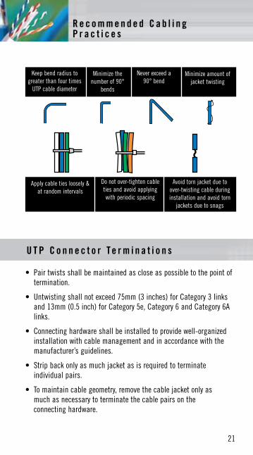
• Pairtwistsshallbemaintainedascloseaspossibletothepointoftermination.
• Untwistingshallnotexceed75mm(3inches)forCategory3linksand 13mm (0.5 inch) for Category 5e, Category 6 and Category 6A links.
• Connectinghardwareshallbeinstalledtoprovidewell-organizedinstallation with cable management and in accordance with the manufacturer’s guidelines.
• Stripbackonlyasmuchjacketasisrequiredtoterminateindividual pairs.
• Tomaintaincablegeometry,removethecablejacketonlyas much as necessary to terminate the cable pairs on the connecting hardware.
Keep bend radius to greater than four times
UTP cable diameter
Minimize the numberof90°
bends
Never exceed a 90°bend
Minimize amount of jacket twisting
Apply cable ties loosely & at random intervals
Do not over-tighten cable ties and avoid applying with periodic spacing
Avoid torn jacket due to over-twisting cable during installation and avoid torn
jackets due to snags
U T P C o n n e c t o r T e r m i n a t i o n s
R e c o m m e n d e d C a b l i n g P r a c t i c e s

22
Communication wire and cable for premise installations in accordance with Article 800 and other applicable parts of the National Electrical Code (NEC) latest issue. Communication wire and cables for Canada are in accordance with the harmonized Canadian Standard Association C22.2 No. 214, Underwriters Laboratories UL 444 latest issue.
Notes: 1. Cables with a higher fire resistance level may be substituted for those with a lower fire resistance level.
2. Non-fire rated outside plant telephone cables may not run outside of a rigid metal conduit more than 50 feet from the point of entrance into a building.
3. Cables rated CMG or CM may be used in runs penetrating one floor (NEC 800-53).
Fire Resistance Test NEC ArticleLevel Requirement 800 725 760 820
(Highest) Plenum NFPA 262 (Steiner tunnel) CMP CL3P FPLP CATVPCables CSA-CMP (Steiner tunnel) CL2P
Riser Cables UL-1666 (Vertical Shaft) CMR CL3R FPLR CATVRMultiple Floors CSA-CMG (Vertical Tray) CL2R
General Purpose UL-1581 (Vertical Tray) CMG CL3 FPL CATVCables CM CL2
(Lowest) Residential CSA-CMG (Vertical Tray) CMX CL2X CATVXCables Restricted Use UL-1581 VW-1 CL3X
N E C F i r e R e s i s t a n c e L e v e l s
N E C F i r e R e s i s t a n c e L e v e l s
23
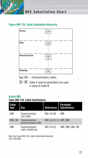
Article 800Table 800-154. Cable Substitutions
Type CM — Communications cables
A B Cable A shall be permitted to be used in place of Cable B
Note: See Figure 800-154. Cable Substitution HierarchyFrom 2005 NEC
Figure 800-154. Cable Substitution Hierarchy
Cable PermittedType Use References Substitutions
CMR Communications 800-154 (B) CMP riser cable
CMG, CM Communications 800-154 (E) (1) CMP, CMR general purpose cable
CMX Communications 800-154 (E) CMP, CMR, CMG, CM cable, limited use
N E C S u b s t i t u t i o n C h a r t
24
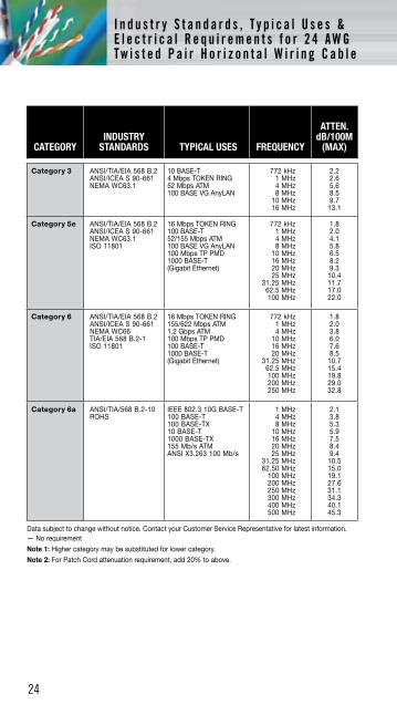
CATEGORYINDUSTRY
STANDARDS TYPICAL USES FREQUENCY
ATTEN.dB/100M
(MAX)
Category 3 ANSI/TIA/EIA 568 B.2 ANSI/ICEA S 90-661 NEMA WC63.1
10 BASE-T 4 Mbps TOKEN RING 52 Mbps ATM 100 BASE VG AnyLAN
772 kHz 1 MHz 4 MHz 8 MHz
10 MHz 16 MHz
2.2 2.6 5.6 8.5 9.7
13.1
Category 5e ANSI/TIA/EIA 568 B.2 ANSI/ICEA S 90-661 NEMA WC63.1 ISO 11801
16 Mbps TOKEN RING 100 BASE-T 52/155 Mbps ATM 100 BASE VG AnyLAN 100 Mbps TP PMD 1000 BASE-T (Gigabit Ethernet)
772 kHz 1 MHz 4 MHz 8 MHz
10 MHz 16 MHz 20 MHz 25 MHz
31.25 MHz 62.5 MHz 100 MHz
1.8 2.0 4.1 5.8 6.5 8.2 9.3
10.4 11.7 17.0 22.0
Category 6 ANSI/TIA/EIA 568 B.2 ANSI/ICEA S 90-661 NEMA WC66 TIA/EIA 568 B.2-1 ISO 11801
16 Mbps TOKEN RING 155/622 Mbps ATM 1.2 Gbps ATM 100 Mbps TP PMD 100 BASE-T 1000 BASE-T (Gigabit Ethernet)
772 kHz 1 MHz 4 MHz
10 MHz 16 MHz 20 MHz
31.25 MHz 62.5 MHz 100 MHz 200 MHz 250 MHz
1.8 2.0 3.8 6.0 7.6 8.5
10.7 15.4 19.8 29.0 32.8
Category 6a ANSI/TIA/568 B.2-10 ROHS
IEEE 802.3 10G BASE-T 100 BASE-T 100 BASE-TX 10 BASE-T 1000 BASE-TX 155 Mb/s ATM ANSI X3.263 100 Mb/s
1 MHz 4 MHz 8 MHz
10 MHz 16 MHz 20 MHz 25 MHz
31.25 MHz 62.50 MHz
100 MHz 200 MHz 250 MHz 300 MHz 400 MHz 500 MHz
2.1 3.8 5.3 5.9 7.5 8.4 9.4
10.5 15.0 19.1 27.6 31.1 34.3 40.1 45.3
Data subject to change without notice. Contact your Customer Service Representative for latest information.— No requirement
Note 1: Higher category may be substituted for lower category.
Note 2: For Patch Cord attenuation requirement, add 20% to above.
I n d u s t r y S t a n d a r d s , T y p i c a l U s e s &E l e c t r i c a l R e q u i r e m e n t s f o r 2 4 A W G T w i s t e d P a i r H o r i z o n t a l W i r i n g C a b l e
25
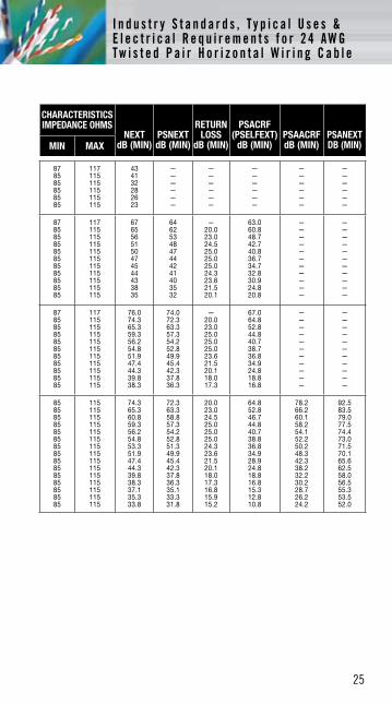
CHARACTERISTICS IMPEDANCE OHMS
NEXTdB (MIN)
PSNEXTdB (MIN)
RETURN LOSS
dB (MIN)
PSACRF(PSELFEXT)
dB (MIN)PSAACRFdB (MIN)
PSANEXT DB (MIN)MIN MAX
87 85 85 85 85 85
117 115 115 115 115 115
43 41 32 28 26 23
— — — — — —
— — — — — —
— — — — — —
— — — — — —
— — — — — —
87 85 85 85 85 85 85 85 85 85 85
117 115 115 115 115 115 115 115 115 115 115
67 65 56 51 50 47 45 44 43 38 35
64 62 53 48 47 44 42 41 40 35 32
— 20.0 23.0 24.5 25.0 25.0 25.0 24.3 23.6 21.5 20.1
63.0 60.8 48.7 42.7 40.8 36.7 34.7 32.8 30.9 24.8 20.8
— — — — — — — — — — —
— — — — — — — — — — —
87 85 85 85 85 85 85 85 85 85 85
117 115 115 115 115 115 115 115 115 115 115
76.0 74.3 65.3 59.3 56.2 54.8 51.9 47.4 44.3 39.8 38.3
74.0 72.3 63.3 57.3 54.2 52.8 49.9 45.4 42.3 37.8 36.3
— 20.0 23.0 25.0 25.0 25.0 23.6 21.5 20.1 18.0 17.3
67.0 64.8 52.8 44.8 40.7 38.7 36.8 34.9 24.8 18.8 16.8
— — — — — — — — — — —
— — — — — — — — — — —
85 85 85 85 85 85 85 85 85 85 85 85 85 85 85
115 115 115 115 115 115 115 115 115 115 115 115 115 115 115
74.3 65.3 60.8 59.3 56.2 54.8 53.3 51.9 47.4 44.3 39.8 38.3 37.1 35.3 33.8
72.3 63.3 58.8 57.3 54.2 52.8 51.3 49.9 45.4 42.3 37.8 36.3 35.1 33.3 31.8
20.0 23.0 24.5 25.0 25.0 25.0 24.3 23.6 21.5 20.1 18.0 17.3 16.8 15.9 15.2
64.8 52.8 46.7 44.8 40.7 38.8 36.8 34.9 28.9 24.8 18.8 16.8 15.3 12.8 10.8
78.2 66.2 60.1 58.2 54.1 52.2 50.2 48.3 42.3 38.2 32.2 30.2 28.7 26.2 24.2
92.5 83.5 79.0 77.5 74.4 73.0 71.5 70.1 65.6 62.5 58.0 56.5 55.3 53.5 52.0
I n d u s t r y S t a n d a r d s , T y p i c a l U s e s &E l e c t r i c a l R e q u i r e m e n t s f o r 2 4 A W G T w i s t e d P a i r H o r i z o n t a l W i r i n g C a b l e

27
N O T E S

28
N O T E S

All information in this document is presented solely as a guide and is believed to be reliable. All printing errors are subject to correction in subsequent releases of this guide, although General Cable has taken precautions to ensure accuracy.
GENERAL CABLE, GENSPEED, FLEX-SEPARATOR, MOSAIC CROSSBLOCK and 10 MTP are trademarks of General Cable Technologies Corporation.
© 2009. General Cable Technologies Corporation. Highland Heights, KY 41076 All rights reserved.
No part of this publication may be reproduced or transmitted in any form or by any means, electronic or mechanical, including photocopying, recording, or any information storage and retrieval system, without written permission.
N O T E S

4 Tesseneer DriveHighland Heights, KY 41076-9753
Phone: 1.800.424.56661.859.572.8000
www.generalcable.comDAT-0001-0609 36005
®