Embed Size (px)
Citation preview
Electrical Machines and Drives 1/1 Collection of Exercises
Darmstadt University of Technology Institute of Electrical Energy Conversion
PPrreeppaarraattiioonn ffoorr EExxaammiinnaattiioonn
The examination is done in writing, where your ability to calculate some problems, is examined.
Some theoretical questions are given, where your understanding of theory is checked.
We recommend the preparation for examination in the following way: Calculate the examples,
given in the Collection of Exercises, and test yourself by comparing your solutions with those
given in the Collection. The three problems at the test in writing are very similar to those, but a
little bit shorter. For theory examination only those questions, which you find hereafter included,
will be asked. Thus the content for learning is exactly defined.
Please note, that the text book contains much more information about motors, than you will need
for the examination. We advice you to prepare the collection of questions, when you are learning
for the exam, and try to find the answers from the text book. If you have difficulties in answering
the questions, do not hesitate to consult us.
If you have any further questions concerning the examination, theory or methods of calculation,
do not hesitate to contact us.
Yours sincerely
A. Binder Darmstadt, 17.02.2012
Electrical Machines and Drives 1/2 Collection of Exercises
Darmstadt University of Technology Institute of Electrical Energy Conversion
TThheeoorryy QQuueessttiioonnss ffoorr tthhee EExxaammiinnaattiioonn
Chapter 2. Rotating Fields in Electrical Machines
2.1 What is a rotating field and how is it generated? Explain the movement of the air gap
field of a three-phase winding graphically!
2.2 How are three-phase windings normally designed? Explain similarities and differences
between single and two-layer windings.
2.3 Describe the squirrel cage as a special case of a poly-phase winding.
2.4 Explain the difference between concentric coils and coils with identical coil span. What is
the effect of these coil forms on the design of the winding overhang (sketch)? Which of
these coil forms are preferred for wire-wound coil windings/shaped-wire windings, low
voltage/high voltage windings?
2.5 What is the magnetic voltage (m.m.f.)? How is the distribution of the magnetic voltage
inside the air gap of a machine determined? Which simplifications does this derivation
base on?
2.6 Explain the mathematical principle of the generation of a rotating field (fundamental !) as
the superposition of standing pulsating fields (corresponding to the excitation of single
phases) with the cancellation of certain positive and negative phase-sequence fields!
2.7 What is the synchronous angular velocity and corresponding circumference speed?
Give numerical values for
a) a small standard induction machine, shaft height 132 mm, four poles, 7.5 kW, 50 Hz,
stator bore diameter 130 mm,
b) a large synchronous hydro-generator, 38 MVA, 64 poles, 50 Hz, 6.8 m stator bore
diameter (bulb-type generator, Danube river power station, Greifenstein, Austria)
2.8 Give the synchronous speed and the circumference velocity of a hydrogen-cooled turbo
generator: 50 Hz, 880 MVA, stator bore diameter 1.35 m, two poles. Why are turbo
generators the mechanically highest stressed type of electrical machines! How is the rotor
therefore constructed?
Chapter 3. Mathematical Analysis of Air Gap Fields
3.1 Explain the distribution, pitching and winding factor using the FOURIER analysis.
Explain the term “slot harmonics”.
3.2 Why does a 6-phase winding approach the desired sinusoidal field distribution better than
a three-phase winding (note: regard the general expression to calculate the ordinal
numbers of harmonics)? How do the time phasors of the corresponding phase currents
look like?
3.3 Symmetrical rotating field windings excite both a fundamental air gap field and harmonic
fields. Which ordinal numbers occur when using a three-phase winding? Discuss the
terms positive and negative phase-sequence system. How do the amplitudes of the air gap
fields decrease with increasing ordinal numbers?
Electrical Machines and Drives 1/3 Collection of Exercises
Darmstadt University of Technology Institute of Electrical Energy Conversion
3.4 Explain the influence of short-pitching and the number of slots per pole on the amplitude
of the harmonic fields!
3.5 Why do normally only odd ordinal numbers of harmonics occur that are not divisible by
three?
Chapter 4. Voltage Induction in Rotary Machines
4.1 The air gap field of a synchronous generator is not ideally sinusoidal, even though the
shape of the pole shoes has been optimised. Nevertheless, the induced line-to-line voltage
is almost ideally sinusoidal. Why?
Why does the corresponding phase voltage in general contain a higher number of
harmonics than the line-to-line voltage?
4.2 The voltage induction can be experienced as two different effects, depending on the
location of the observer, namely stationary induction and induction by movement.
Explain these terms using the example of a simple conductor loop in a magnetic field.
What is the meaning of the terms “transformer” and “rotationally” voltage induction,
which are used with rotating electrical machines?
4.3 A sinusoidal field wave rotating with constant speed induces a sinusoidal voltage in a coil
located in the stator slots of a machine. Which kind of induction (stationary or motion
induction) does an observer see, who travels with the rotating field? Give the formula!
4.4 Why is the total field inductance of a three-phase winding higher than the “fundamental
wave” inductance? What is the meaning of “harmonic leakage”?
4.5 How is the fundamental magnetising inductance calculated? Explain the calculation in the
following steps: A three-phase winding is supplied with a symmetrical three-phase
current system I and therefore excites a rotating field with the air gap field fundamental
Bδ (saturation of iron neglected). This induces a voltage U in each phase (three-phase
voltage system), thus yielding a reactance X = U/I per phase, which leads to a rotating
field inductance per phase.
4.6 Explain the effect of the short-pitching factor of a chorded (short-pitched) winding on the
voltage induction of harmonics in comparison to a full-pitch coil.
4.7 Explain the effect of the distribution factor of a coil group made of two unchorded coils
from the phasor diagram of the induced voltages of the two coils.
4.8 Explain the mutual inductance between two phases of two three-phase windings, if one
phase is located in the stator whereas the other one is in the rotor.
4.9 Explain the operation principle of a rotary transformer (variable transformer)? What are
the main advantages and disadvantages in comparison to standard transformers in three-
limb core design?
Chapter 5. The Slipring Induction Machine
5.1 Explain the operation principle of a slipring induction machine in general. How can the
M(n)-characteristic be explained physically ?
Electrical Machines and Drives 1/4 Collection of Exercises
Darmstadt University of Technology Institute of Electrical Energy Conversion
5.2 Some major assumptions have been made when deriving the T-equivalent circuit of the
induction machine. Which?
5.3 Give the stator and rotor voltage equations per phase of the induction machine. Draw the
T-equivalent circuit. Which parameters occur in the equivalent circuit of the induction
machine?
5.4 What is the advantage of transforming the rotor quantities current, voltage, flux linkage,
resistance and inductance to the stator side using a transformation ratio ü? In general, can
ü be chosen arbitrarily? If so, show why! Which transformation ratio ü is commonly used
with induction machines?
5.5 Why do we have to distinguish two different transformation ratios in case of squirrel cage
machines? Which transformation ratios do we need?
5.6 What is the slip? Equation? What is its physical meaning? Which operating points
correspond to slip –1,0,1,2 ?
5.7 How big is the slip of an induction machine running at no-load, at rated load (typical
values) and at stand-still? How big are the rotor frequencies in these cases assuming
stator frequencies of a) 50 Hz and b) 60 Hz?
5.8 When deriving the equivalent circuit of the induction machine from the rotating field
theory (air gap field!), the leakage inductances of the winding leakage fluxes had to be
added afterwards. Which leakage fluxes are these? Sketch the distribution of these
leakage fluxes in the machine.
5.9 What is the magnetising current of an induction machine? In which case does this current
actually flow in the phase windings of the machine?
5.10 What is the internal (or “electric”) torque of an induction machine? How does it depend
on the “air gap power”? Is it bigger or smaller than the shaft torque in motor and
generator operation?
5.11 Which losses occur in induction machines? Determine an equation for the efficiency for
motor and generator operation. Which of the different loss groups are already included in
the equivalent circuit of the induction machine?
5.12 Is it true, that the breakdown slip of induction machines is the same for motor and
generator operation when the stator resistance is considered (Rs ≠ 0)? If so, is this also
true for the breakdown torques? If not, why? What happens when the stator resistance is
neglected (Rs = 0)?
5.13 The equivalent circuit of induction machines has been derived for the fundamentals of the
stator and rotor air gap fields. Which part of the leakage flux is due to the effect of
harmonic air gap fields to the equivalent circuit? Discuss the BLONDEL leakage
coefficient σ and explain how to determine this coefficient by measurement!
5.14 Draw a qualitative voltage and current phasor diagram of an induction machine operating
at a constant stator voltage at rated load! Use the consumer reference-arrow system!
Electrical Machines and Drives 1/5 Collection of Exercises
Darmstadt University of Technology Institute of Electrical Energy Conversion
5.15 Draw qualitatively a current locus diagram of an induction machine with consideration of
the stator resistance (OSSANNA circle) and label special points (s = 0, s = sb) as well as s
= 1 and s = ∞! Add the torque and the power line. How can these lines be used to
determine the internal torque, the mechanical output power and the resistive losses in
both stator and rotor winding?
5.16 How can we label the locus diagram with the slip using a slip-line? Which operating
points do we need to know? Give a qualitative sketch!
5.17 How big is typically the no-load current and the starting current of induction machines
operated at the grid, with respect to the rated current? How big is typically the breakdown
and the starting torque of a deep-bar rotor induction machine, with respect to rated
torque?
5.18 Give the stator and rotor voltage equations of an induction machine according to the
equivalent circuit! Determine the dependence of the rotor current on the stator current.
Discuss this relation for s = 0, s = 1 and s = ∞, concerning current amplitude and phase
shift with respect to the stator current!
5.19 Sketch the locus diagram neglecting the stator resistance (HEYLAND-circle). How can
torque and power line be used to determine the mechanical output power, the inner
torque, the rotor losses and the stator current ?
5.20 Use a sketch of the locus diagram to determine the stator current of an induction machine
(motor/generator), the corresponding cosϕ and the mechanical power in a slip range -1 ...
1 ! What happens to the current, if the voltage drops to 50 % of the prior value? How
does the torque depend on the voltage?
5.21 What is KLOSS´ relation (formula)? On which simplifying assumption is it based? How
does the corresponding torque-speed diagram look like? Sketch!
5.22 The following example shows, that many important values for correct operation can be
found on the nameplate of an induction machine: Induction machine, 400V/690V D/Y,
950A D, 560 kW, 1492kW, 50Hz, cosϕ = 0.88. Use these values to determine the
efficiency, the shaft torque, the total losses, the number of poles, and the rated slip of the
machine!
5.23 Sketch the energy flow of an induction machine for motor and generator operation!
Discuss the losses!
5.24 Explain the possibilities to change the operational behaviour of a slipring induction
machine using external rotor resistances. Why does it still make sense to use a slipring
induction motor as a variable speed pump drive, when considering the additional losses in
the rotor resistors?
Chapter 6. The Squirrel Cage Induction Machine
6.1 What is current displacement? Where and why does it occur in squirrel cage induction
machines? How is current displacement used to improve the operational behaviour of
squirrel cage induction machines?
Electrical Machines and Drives 1/6 Collection of Exercises
Darmstadt University of Technology Institute of Electrical Energy Conversion
6.2 Discuss the dependence of the bar resistance and the slot leakage inductance on the rotor
frequency! Sketch the corresponding curves! By how much does the rotor bar resistance
of a deep copper bar rotor increase at 50 Hz and 75 °C (bar width = slot width) at a bar
height of 5 cm?
6.3 What is the influence of current displacement on the M(n)-characteristic of an induction
machine? (Sketch). Draw rotor bar shapes that lead to a a) weak and b) strong influence
of current displacement on the resistance and the slot leakage inductance and explain the
results!
6.4 Is it true, that under identical motor geometry a copper bar in a rectangular slot has a
stronger current displacement than an aluminium bar? Remark: electric conductivity:
copper (20°C): 57.10
6 S/m , aluminium 34
.10
6 S/m.
6.5 Which problems occur during line-starting of induction machines? How can this problem
be handled with a slipring induction machine?
6.6 Why is the breakdown torque of a slipring or round bar cage rotor induction machine
higher than the breakdown torque of deep-bar of double-bar cage rotors with similar
stator parameters?
Chapter 7. Induction Machine Based Drive Systems
7.1 Explain the “quasi-static” stability of operating points of induction machines using the
steady-state Me(n) motor characteristic together with typical load characteristics Ms(n).
7.2 How big is the energy that is dissipated in the rotor cage of an induction machine that
drives a centrifuge, if the centrifuge is accelerated from 0 to 3000 /min at no load? The
polar momentum of inertia of the centrifuge and the rotor is 15 kgm2.
7.3 Sketch the M(n)-characteristics of typical load machines ! Give and discuss applications!
7.4 Describe the operating principle of a pole-changing winding according to DAHLANDER !
Which are the advantages and disadvantages when compared to motors with two
independent windings for different speeds? Which are the main applications of drives
with two distinctive speeds? Which alternative is provided by inverter-fed variable speed
drives?
7.5 Rotor-fed induction machines are sometimes used in wind generators, as variable
frequency rotor supply allows for limited variable speed generator operation. Explain the
operating principle of rotor supply with a variable frequency voltage! How can we obtain
sub- or supersynchronous operation at constant current? Why is this option (bi-directional
converter supplies the rotor circuit) cheaper than supplying the stator with variable
frequency (which are technical limits)?
7.6 Describe the operation of induction machines with stator voltages with variable frequency
f and variable amplitude U (inverter supply)! How are U and f changed to obtain a
constant breakdown torque? Neglect the stator resistance! Sketch the M(n)-characteristics
for different values for U and f !
Electrical Machines and Drives 1/7 Collection of Exercises
Darmstadt University of Technology Institute of Electrical Energy Conversion
7.7 Explain “field weakening” for inverter-fed induction machines. How do U and f need to
be changed in order to achieve field weakening? Why do we often make use of field
weakening to obtain a wide speed range with constant power?
7.8 How has the voltage of inverter-fed induction machines to be changed in order to obtain a
constant flux at variable frequency and thus variable speed: a) with Rs = 0, b) with Rs ≠ 0 ?
In which range of speed and frequency is the stator resistor Rs of dominating influence?
Why?
7.9 What is the advantage of inverter supply of induction machines (voltage source inverter)
with pulse width modulated voltage when compared with block voltage supply? What is
the effect of this method with a sufficiently high pulse frequency on the shape of the
stator current of the induction machines?
7.10 Explain the principle of Y/∆-starting! Which advantages do we get and what are the
disadvantages?
7.11 What is “four-quadrant operation”? Give the sign of speed and torque in all four
quadrants. How do we achieve this operation with a voltage source inverter and an
induction machine?
Which are the prerequisites concerning the inverter, if we want to feed power back into
the grid (regenerative braking)?
7.12 Describe the terms
a) counter-current braking (braking by reversal) and
b) supersynchronous braking
by the torque-speed characteristic of induction machines.
7.13 Is it possible to operate an induction machine on a grid with cosϕ = 1? Explain your
answer! With which additional devices would this operation be possible?
Chapter 8. The Synchronous Machine
8.1 Explain the operating principle of a synchronous machine! Give the basic equation of the
torque-load angle characteristic at fixed voltage and frequency.
8.2 Explain the difference between a round-rotor and a salient-pole synchronous machine
a) in terms of construction (sketch !) and
b) in terms of torque generation (M(ϑ)-characteristic).
8.3 Draw the voltage and current phasor diagram of an overexcited round-rotor synchronous
machine in generator operation in the consumer reference-arrow system!
8.4 What is the effect of salient rotor poles on the magnetising inductance of the stator
winding? Explain the terms d- and q-axis as well as Ld and Lq !
8.5 Draw the voltage and current phasor diagram of an overexcited salient-pole synchronous
machine in generator operation in the consumer reference-arrow system!
Electrical Machines and Drives 1/8 Collection of Exercises
Darmstadt University of Technology Institute of Electrical Energy Conversion
8.6 What is the definition of the load angle ϑ in synchronous machines? Why does it not
make sense to define a load angle with induction machines?
8.7 Draw qualitatively the voltage phasor diagram of the overexcited round-rotor
synchronous machine in motor and generator operation (consumer reference-arrow
system) and label the load angle. Determine from the sign of the load angle and from the
round-rotor machine power equation (Rs = 0) the direction of energy flow.
8.8 Explain graphically for the example of a round-rotor machine voltage phasor diagram
(consumer reference-arrow system, Rs = 0) the terms “overexcited”, “underexcited”,
“motor” and “generator” operation (4 different cases) !
8.9 Why is a capacitor bank connected in parallel to an induction machine generator
operating in an isolated grid, whereas no capacitor bank is required with isolated
synchronous generators?
8.10 Explain phase shifter operation of a synchronous machine using the phasor diagram
(consumer reference-arrow system, Rs = 0)! What are phase shifters used for? How big is
the shaft power?
8.11 An unexcited synchronous machine is running at a grid without any mechanical load (no
power consumption or generation, machine is assumed to have no losses). Draw the
phasor diagram. Who is providing the necessary magnetisation of the machine?
8.12 Draw the phasor diagram of a permanently short-circuited synchronous machine running
at rated speed, if the rotor is excited with rated current IfN
a) for Rs = 0,
b) for Rs ≠ 0.
When is it allowed to neglect th e stator resistance Rs and still get an accurate phasor
diagram, at low or at high speed? Why?
8.13 How does the torque of a grid-connected round-rotor synchronous machine change with
increasing mechanical load in motor and generator operation (formula)? Why does it
show a pull-out torque?
8.14 Discuss the quasi-static stability of the grid-connected round-rotor synchronous machine
using the steady-state M(ϑ) characteristic!
8.15 Why is the synchronous machine in stable operation conditions often compared with a
non-linear torsion spring? How do we determine the equivalent torsion spring constant cϑ
? Is this "spring" stiffer at small or at big load and at small or at high field current If ?
Does it make sense to compare a synchronous generator in isolated operation with a
torsional spring?
8.16 Why has the load angle of a synchronous machine, operated at a fixed voltage, a tendency
to oscillate? How does the load torque effect the eigenfrequency of the synchronous
machine? How big is this eigenfrequency roughly at no load and at rated torque?
8.17 Why are big industrial sites with many inductive consumers (e.g. many induction
machines) often equipped with synchronous machines to compensate the reactive load?
What would be alternative countermeasures?
Electrical Machines and Drives 1/9 Collection of Exercises
Darmstadt University of Technology Institute of Electrical Energy Conversion
8.18 Explain the operation of a reluctance machine as a special case of a unexcited grid-
connected salient-pole synchronous machine (motor/generator operation, pull-out
torque)!
8.19 Sketch the M(ϑ)-characteristics of the synchronous reluctance machine for generator and
motor operation!
8.20 Due to technical improvements, many older power stations generators are nowadays
refurbished to increase the efficiency. Discuss the effect of an efficiency increase of 0.3%
of a 750 MW turbo generator! By which value is the on-site heat dissipation per year (in
kWh) reduced?
8.21 Sketch the M(ϑ)-characteristics of a salient-pole synchronous machine for
motor/generator operation! Which load angle range is stable (pull-out load angle)? What
does this characteristic look like, if the excitation is turned off? Which range is now
stable (pull-out load angle)?
8.22 Draw the characteristic Us(Is) of a synchronous generator in isolated operation at a
constant excitation (hence, without voltage control) and resistive load, as well at pure
capacitive and inductive load!
8.23 The synchronous generated voltage Up can be included in the equivalent circuit of the
synchronous machine as an internal voltage source. In which state of operation can this
voltage directly be measured directly at the machine terminals?
8.24 Use the phasor diagram of a round-rotor synchronous machine (Rs = 0) in isolated
generator operation with constant excitation to explain why pure capacitive load will lead
to terminal voltages higher than at no-load!
Discuss the related phenomenon of self-excitation of idle, non-excited synchronous
generators feeding long, open ended lines!
9. Electrically and Permanent Magnet Excited Synchronous Machines
9.1 Sketch the no-load and short-circuit characteristics of a synchronous machine? How are
they determined by measurement?
9.2 How is the saturated synchronous reactance determined considering saturation due to no-
load excitation If0?
Which voltage can be measured at the open terminals of a rotating synchronous machine
with no-load excitation and rated speed?
9.3 What is the “no-load − short-circuit” ratio? What is the definition of the synchronous
reactance? Explain its value for the saturated and the unsaturated synchronous machine
(sketch) !
9.4 Why is the open-circuit characteristic of synchronous machines saturated, whereas the
short-circuit characteristic is not saturated?
9.5 Is a large synchronous reactance at grid operation an indication for high overload
capability (large stability margin), if the excitation and therefore the synchronous
Electrical Machines and Drives 1/10 Collection of Exercises
Darmstadt University of Technology Institute of Electrical Energy Conversion
generated voltage is kept constant? Explain your answer using the M(ϑ)-curve of a round-
rotor synchronous machine (Rs = 0) !
9.6 Which excitation techniques are common with synchronous machines? Draw simple
circuit sketches! Discuss advantages and disadvantages of the various possibilities!
9.7 What is high-speed excitation and what is it needed for? What is the ceiling voltage?
What is the aim of high-speed de-excitation? How is it realised?
9.8 What is the purpose of the damper cage of a synchronous machine? Does a synchronous
machine always need a damper cage, both at grid and isolated operation?
9.9 How does the eigenfrequency of a grid-connected oscillating synchronous machine
change with/without a damper cage? How big is the eigenfrequency roughly?
9.10 Name permanent magnet materials and discuss their properties !
9.11 How is the magnetic operating point of a permanent magnet machine determined?
9.12 Describe the operating principle of a synchronous machine with rotor position control!
9.13 Why do you get maximum torque from synchronous machines when using Iq-current ?
Give a phasor diagram!
Chapter 10. Dynamic Performance of Synchronous Machines
10.1 For rapidly changing currents (loads) at constant speed the synchronous machine is
described as 3 winding transformer in the d-axis and as a 2 winding transformer in the q-
axis, additionally to the rotary voltage induction.
a) Why can this transformer effect be omitted during steady-state synchronous
operation, where currents are changing sinusoidally with synchronous frequency?
b) Which windings are “involved” in the 3-, which are involved in the 2-winding
transformer?
c) Draw equivalent circuits for these transformer configurations!
10.2 Explain the terms “transient” and “subtransient” reactance using the d-axis transformer
equivalent representation of the synchronous machine? Give typical per unit values!
10.3 Why does the q-axis only have a subtransient, but no transient reactance? Determine the
subtransient reactance of the q-axis from the 2-winding equivalent transformer!
10.4 Name typical orders of magnitude of the different reactances of synchronous machines in
p.u.-values! Which reactances are the smallest and why?
10.5 Give an approximate formula for the calculation of the magnitude of the sudden short-
circuit current of synchronous machines with damper cage! Is the sudden short-circuit
current larger than the steady-state short circuit current? If so, why and by typically
which value?
10.6 When does the sudden short-circuit need to happen - with respect to the terminal voltage -
to cause the maximum current amplitude? When does it need to happen to cause the
Electrical Machines and Drives 1/11 Collection of Exercises
Darmstadt University of Technology Institute of Electrical Energy Conversion
minimum current amplitude? Why is it inevitable in case of three-phase machines that at
least one phase will suffer from (nearly) maximum short circuit current amplitude?
Chapter 11. DC Machines
11.1 Explain the operating principle of a dc machine! Which machine components are needed?
11.2 How does the mechanical rectification of the induced armature ac voltage work in dc
machines? How do we achieve a rectified armature voltage with almost no residual
ripple? How big is the frequency of this ripple voltage? What are physical reasons for this
(small) ripple in the armature voltage?
11.3 How big is the frequency of the ac magnetisation of the rotating iron core? What is the
effect of this ac magnetisation? Why has the rotor iron core to be laminated?
11.4 Name the basic formulas of the dc machine: induced voltage, electromagnetic torque,
terminal voltage for motor and generator operation!
11.5 Sketch the distribution of the air gap field of an uncompensated dc machine without inter-
pole windings for If > 0 at a) no load (Ia = 0) and b) at load (Ia > 0) over two pole pitches.
Label the flux loss due to saturation in case b) caused by the armature reaction.
11.6 Sketch the (saturated) no-load characteristic U0(If) of a dc generator at constant speed
n = const. How can it be measured? Where is the magnetising field saturation mainly
located in the iron core of dc machines?
11.7 What is “commutation” of dc machines? What are problems caused by commutation for
the operation of dc machines? Explain the term “reactance voltage”.
11.8 Describe the operation principle of inter-pole windings. Can we achieve almost sparkless
commutation for any arbitrary combination of n and Ia, hence for any speed and load?
11.9 Which are typical power limits for dc machines? Discuss these limits compared with
squirrel-cage induction machines!
11.10 Describe the operating principle of the simplex armature lap and wave winding using coil
sketches including the connection to the commutator! What are the electric differences
between lap and wave windings? What are the consequences for technical applications?
11.11 How does the compensation winding of dc machines work (Sketch)? What are “first kind
compensators”? What are they needed for? (Sketch)
11.12 Sketch the four basic connection options of dc machines! What are the field regulating
resistor (field rheostat) and the starting resistor needed for?
11.13 Sketch the U(Ia) characteristic of a separately excited dc generator with and without
compensation winding! How can it be measured?
11.14 How does self-excitation with shunt-wound dc generators work?
11.15 Sketch the n(M)-characteristic
Electrical Machines and Drives 1/12 Collection of Exercises
Darmstadt University of Technology Institute of Electrical Energy Conversion
a) of a separately excited, compensated motor and
b) of a series-wound motor.
Discuss at these two characteristics: motor reaction to unloading and the speed drop with
increasing load!
11.16 Describe the quasi-static stability of a shunt-wound dc machine with the influence of
armature reaction. What is the mathematical requirement for stability?
11.17 What is a WARD-LEONARD-converter ? What was/is it used for?
11.18 How can we achieve variable speed with dc machines by power electronics? Give
examples by sketching the circuits!
11.19 Sketch the one-quadrant family of characteristics of a converter-fed, separately excited,
compensated dc machine including field weakening operation.
11.20 At high speed, the reactance voltage needs to be limited to approximately which value, in
order to limit spark generation? How do the corresponding characteristics look like: M(n), Ia(n), U(n), Φ(n), considering this effect?
11.21 How big is typically the voltage drop across the brushes of dc machines? How does
voltage vs. current density in the brushes look like?
11.22 Explain “over-“ and “under-commutation” of dc machines? Why can over-commutation
cause instability of a separately excited motor?
11.23 Sketch the field lines of the inter-pole field of a dc machine schematically (two pole
equivalent machine)! How does the ratio of number of turns per pole of the inter-pole
winding NW,pole and the armature winding Na,pole = z/(8ap) of an uncompensated dc
machine need to be chosen to obtain a positive inter-pole field in the inter-pole air gap?
11.24 Name typical limit values
a) for the reactance voltage for steady-state operation and intermittent operation (e.g.
rolling mill applications),
b) the medium and the maximum permissible voltage between two commutator
segments and
c) the steady-state current densities of the bush contact faces.
Electrical Machines and Drives 1/13 Collection of Exercises
Darmstadt University of Technology Institute of Electrical Energy Conversion
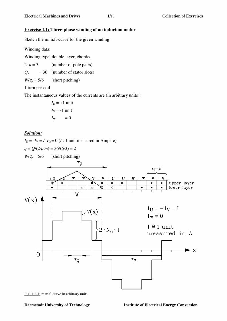
Exercise 1.1: Three-phase winding of an induction motor
Sketch the m.m.f.-curve for the given winding!
Winding data:
Winding type: double layer, chorded
2⋅ p = 3 (number of pole pairs)
Qs = 36 (number of stator slots)
W/τp = 5/6 (short pitching)
1 turn per coil
The instantaneous values of the currents are (in arbitrary units):
IU = +1 unit
IV = -1 unit
IW = 0.
Solution:
IU = -IV = I, IW = 0 (I : 1 unit measured in Ampere)
q = Q/(2⋅p⋅m) = 36/(6⋅3) = 2
W/τp = 5/6 (short pitching)
Fig. 1.1-1: m.m.f.-curve in arbitrary units
Electrical Machines and Drives 1/14 Collection of Exercises
Darmstadt University of Technology Institute of Electrical Energy Conversion
Exercise 1.2: Three-phase winding of a standard induction motor
Motor data:
UN = 380 V Y (nominal voltage, star connection)
PN = 15 kW (nominal output power)
2⋅p = 6 (number of poles)
fN = 50 Hz (nominal frequency)
data of stator core:
dsi = 200 (bore diameter), lfe = 150 mm (length of core)
Qs = 36 (number of stator slots)
Design a chorded double-layer winding with 5/6 short pitching! What is the number of turns per
coil Nc , if all coils of one phase are connected into series? Select air gap flux density amplitude
between 0.9 and 1 T !
Solution:
Q = 36, W/τp = 5/6. By neglecting the primary voltage drop (Rs + Xsσ)⋅Is the induced voltage Uh
is equal to the supply phase voltage:
V2203
V380
3
Nh ===
UU
mm 150 6, 2 , 200mm mm, 7,1042
πfep ==⋅==
⋅
⋅= lpd
p
dsi
siτ
6
5 2, 0.933, 966.0966.0
)6
πsin(
)6
πsin(
2
πsin :1 ν
ppd1p1w1 ===⋅=
⋅⋅
⋅
⋅=⋅==
ττ
Wq
Wkkk
Hz50 ,m
Vs1,106 ˆ ˆ
π
2π2
2δ,1sδ,1fepwsh ==⋅⇒⋅⋅⋅⋅⋅⋅⋅⋅= fBNBlkNfU τ
For good utilisation of iron, the air-gap induction has to be between 0.9 ... 1 T, so e.g.
T ,950 ˆδ,1 ≈B . An air-gap induction of T ,950 ˆ
δ,1 ≈B leads to induction in the teeth of
T 9,1 ˆ2 δ,1 ≈⋅= BBd , the value when saturation of iron occurs.
Selection of number of turns per coil:
aNqpNN csc /2,75.11195.0/1.106 ⋅⋅===⇒ . With series connection a = 1 we get:
In case of Nc = 9: Ns = 108 and 98.0ˆ1, =δB T
In case of Nc = 10: Ns = 120 and 88.0ˆ1, =δB T . To get the higher field amplitude, Nc = 10 is
chosen.
Electrical Machines and Drives 1/15 Collection of Exercises
Darmstadt University of Technology Institute of Electrical Energy Conversion
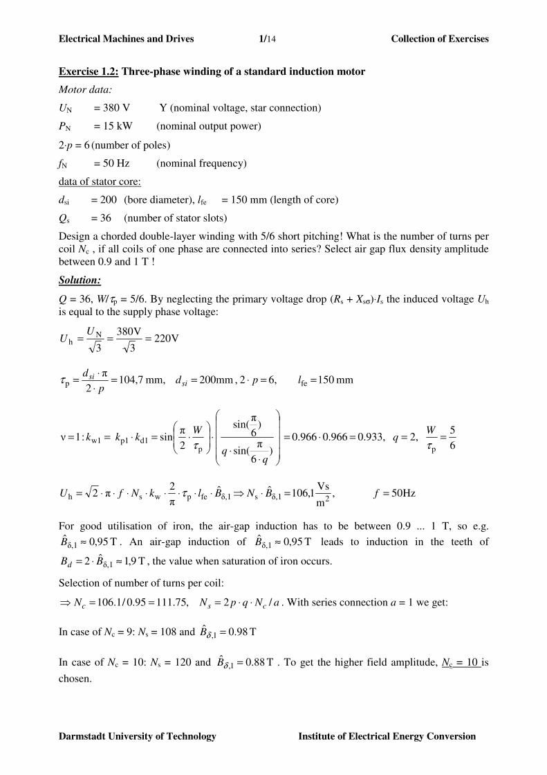
Exercise 1.3: Three-phase winding for a synchronous emergency generator
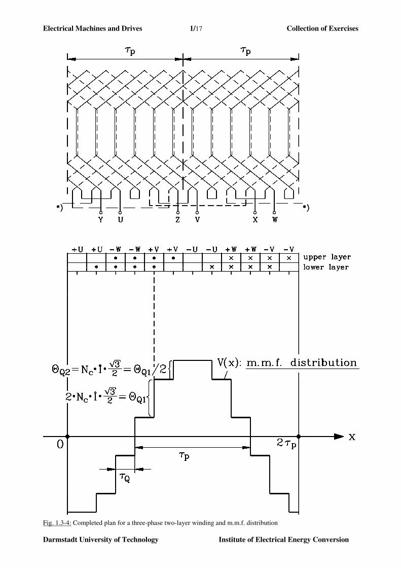
Fig.1.3-1 shows the plan for a three-phase winding. It is the cut-out over two pole pitches.
Fig. 1.3-1: Plan for a three-phase two-layer winding
Electrical Machines and Drives 1/16 Collection of Exercises
Darmstadt University of Technology Institute of Electrical Energy Conversion
1) What is the number of slots per pole and phase q?
2) What is the type of winding:
- single-layer or double-layer winding?
- short-pitch or full-pitch winding?
3) To obtain a three-phase winding, the coils has to be connected. Draw the wiring of the coils
into the plan. Make sure, that a three-phase winding with the terminals U-X, V-Y, W-Z is
obtained!
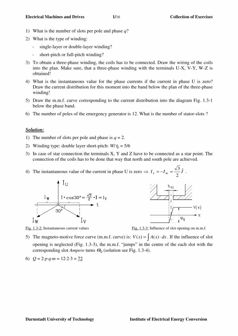
4) What is the instantaneous value for the phase currents if the current in phase U is zero?
Draw the current distribution for this moment into the band below the plan of the three-phase
winding!
5) Draw the m.m.f. curve corresponding to the current distribution into the diagram Fig. 1.3-1
below the phase band.
6) The number of poles of the emergency generator is 12. What is the number of stator-slots ?
Solution:
1) The number of slots per pole and phase is q = 2.
2) Winding type: double layer short-pitch: W/τp = 5/6
3) In case of star connection the terminals X, Y and Z have to be connected as a star point. The
connection of the coils has to be done that way that north and south pole are achieved.
4) The instantaneous value of the current in phase U is zero III ˆ2
3 wv =−=⇒ .
Fig. 1.3-2: Instantaneous current values Fig. 1.3-3: Influence of slot opening on m.m.f.
5) The magneto-motive force curve (m.m.f. curve) is: ∫ ⋅= dxxAxV )()( . If the influence of slot
opening is neglected (Fig. 1.3-3), the m.m.f. “jumps” in the centre of the each slot with the
corresponding slot Ampere turns ΘQ (solution see Fig. 1.3-4).
6) Q = 2⋅p⋅q⋅m = 12⋅2⋅3 = 72
Electrical Machines and Drives 1/17 Collection of Exercises
Darmstadt University of Technology Institute of Electrical Energy Conversion
Fig. 1.3-4: Completed plan for a three-phase two-layer winding and m.m.f. distribution
Electrical Machines and Drives 1/18 Collection of Exercises
Darmstadt University of Technology Institute of Electrical Energy Conversion
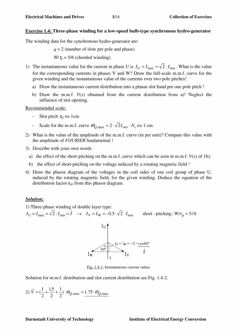
Exercise 1.4: Three-phase winding for a low-speed bulb-type synchronous hydro-generator
The winding data for the synchronous hydro-generator are:
q = 2 (number of slots per pole and phase)
W/τp = 5/6 (chorded winding)
1) The instantaneous value for the current in phase U is rmsmaxU 2 III ⋅== . What is the value
for the corresponding currents in phases V and W? Draw the full-scale m.m.f. curve for the
given winding and the instantaneous value of the currents over two pole pitches!
a) Draw the instantaneous current distribution into a planar slot band per one pole pitch !
b) Draw the m.m.f. V(x) obtained from the current distribution from a)! Neglect the
influence of slot opening.
Recommended scale:
- Slot pitch τQ ⇔ 1cm
- Scale for the m.m.f. curve crmsQ NI ⋅⋅= 22max,Θ ⇔ 1 cm.
2) What is the value of the amplitude of the m.m.f. curve (in per unit)? Compare this value with
the amplitude of FOURIER fundamental !
3) Describe with your own words
a) the effect of the short-pitching on the m.m.f. curve which can be seen in m.m.f. V(x) of 1b),
b) the effect of short-pitching on the voltage induced by a rotating magnetic field !
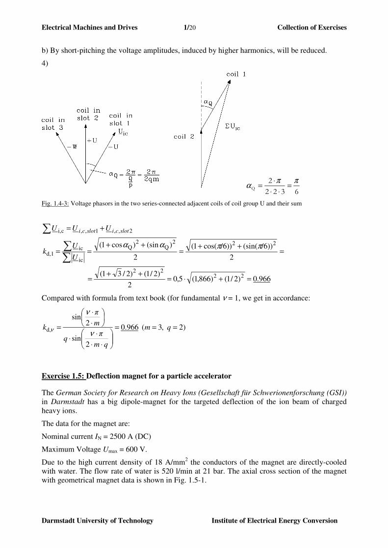
4) Draw the phasor diagram of the voltages in the coil sides of one coil group of phase U,
induced by the rotating magnetic field, for the given winding. Deduce the equation of the
distribution factor kd1 from this phasor diagram.
Solution:
1) Three-phase winding of double layer type:
6/5 W/:pitching-short20.5- ˆ 2 prmsWVrmsmaxU =⋅⋅==→=⋅== τIIIIIII
Fig. 1.4-1: Instantaneous current values
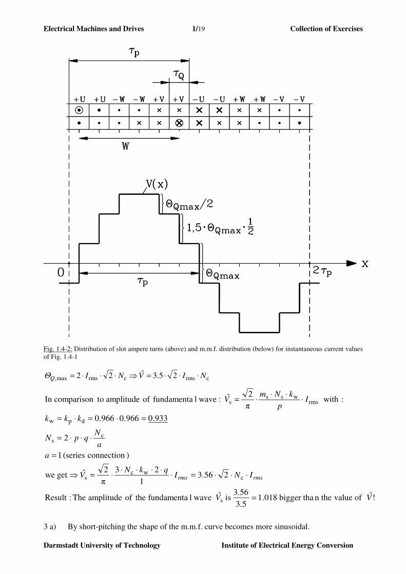
Solution for m.m.f. distribution and slot current distribution see Fig. 1.4-2.
2) max,max, 75.1)2
1
2
5,1
2
1(ˆ
QQ ΘΘV ⋅=⋅++=
Electrical Machines and Drives 1/19 Collection of Exercises
Darmstadt University of Technology Institute of Electrical Energy Conversion
Fig. 1.4-2: Distribution of slot ampere turns (above) and m.m.f. distribution (below) for instantaneous current values
of Fig. 1.4-1
crmscrmsmax, 25.3ˆ22 NIVNIQ ⋅⋅⋅=⇒⋅⋅⋅=Θ
!ˆ of valuen thebigger tha 018.13.5
3.56 is ˆ wavelfundamenta theof amplitude The :Result
256.31
23
π
2ˆget we
)connection (series 1
2
933.0966.0966.0
: withπ
2ˆ: wavelfundamenta of amplitude tocomparisonIn
s
cwc
s
cs
dpw
rmswss
s
VV
INIqkN
V
a
a
NqpN
kkk
Ip
kNmV
rmsrms
=
⋅⋅⋅=⋅⋅⋅⋅⋅
⋅=⇒
=
⋅⋅⋅=
=⋅=⋅=
⋅⋅⋅
⋅=
3 a) By short-pitching the shape of the m.m.f. curve becomes more sinusoidal.
Electrical Machines and Drives 1/20 Collection of Exercises
Darmstadt University of Technology Institute of Electrical Energy Conversion
b) By short-pitching the voltage amplitudes, induced by higher harmonics, will be reduced.
4)
6322
2Q
ππα =
⋅⋅
⋅=
Fig. 1.4-3: Voltage phasors in the two series-connected adjacent coils of coil group U and their sum
966.0)2/1()866,1(5,02
)2/1()2/31(
2
))/6(sin())/6cos(1(
2
)(sin)cos1(
2222
222Q
2Q
ic
icd,1
2,,1,,ci,
=+⋅=++
=
=++
=++
==
+=
∑∑
∑
ππαα
U
Uk
UUU slotcislotci
Compared with formula from text book (for fundamental ν = 1, we get in accordance:
)2 ,3( 966.0
2sin
2sin
d, ===
⋅⋅
⋅⋅
⋅
⋅
= qm
qm
πq
m
π
kν
ν
ν
Exercise 1.5: Deflection magnet for a particle accelerator
The German Society for Research on Heavy Ions (Gesellschaft für Schwerionenforschung (GSI)) in Darmstadt has a big dipole-magnet for the targeted deflection of the ion beam of charged
heavy ions.
The data for the magnet are:
Nominal current IN = 2500 A (DC)
Maximum Voltage Umax = 600 V.
Due to the high current density of 18 A/mm2 the conductors of the magnet are directly-cooled
with water. The flow rate of water is 520 l/min at 21 bar. The axial cross section of the magnet
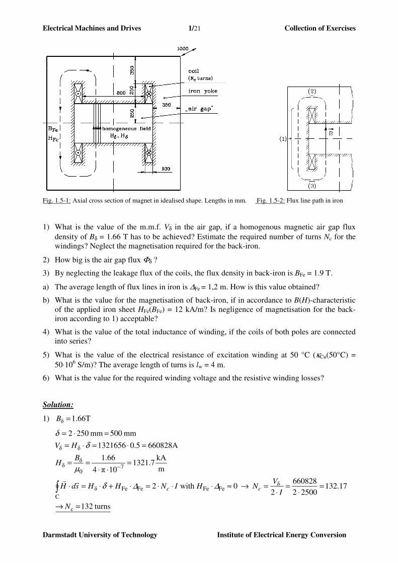
with geometrical magnet data is shown in Fig. 1.5-1.
Electrical Machines and Drives 1/21 Collection of Exercises
Darmstadt University of Technology Institute of Electrical Energy Conversion
Fig. 1.5-1: Axial cross section of magnet in idealised shape. Lengths in mm. Fig. 1.5-2: Flux line path in iron
1) What is the value of the m.m.f. Vδ in the air gap, if a homogenous magnetic air gap flux
density of Bδ = 1.66 T has to be achieved? Estimate the required number of turns Nc for the
windings? Neglect the magnetisation required for the back-iron.
2) How big is the air gap flux Φδ ?
3) By neglecting the leakage flux of the coils, the flux density in back-iron is BFe = 1.9 T.
a) The average length of flux lines in iron is ∆Fe = 1,2 m. How is this value obtained?
b) What is the value for the magnetisation of back-iron, if in accordance to B(H)-characteristic
of the applied iron sheet HFe(BFe) = 12 kA/m? Is negligence of magnetisation for the back-
iron according to 1) acceptable?
4) What is the value of the total inductance of winding, if the coils of both poles are connected
into series?
5) What is the value of the electrical resistance of excitation winding at 50 °C (κCu(50°C) =
50⋅106 S/m)? The average length of turns is lw = 4 m.
6) What is the value for the required winding voltage and the resistive winding losses?
Solution:
1) T66.1δ =B
turns132
17.13225002
660828
2 0 with 2
m
kA7.1321
10π4
66.1
A6608285.01321656
mm 500 mm 2502
c
δFeFeFeFeδ
C
70
δδ
δδ
=→
=⋅
=⋅
=→≈⋅⋅⋅=⋅+⋅=⋅
=⋅⋅
==
=⋅=⋅=
=⋅=
∫
−
N
I
VNHINHHsdH
BH
HV
cc ∆∆δ
µ
δ
δ
rr
Electrical Machines and Drives 1/22 Collection of Exercises
Darmstadt University of Technology Institute of Electrical Energy Conversion
2) Wb328.1Wb0.18.066.1FepδPoleδ
A
δδ =⋅⋅=⋅⋅=⋅≅⋅= ∫ lbBABAdBΦ
rr
mm1000 mm,800 Fep == lb
3) a) Flux line in iron: According to Fig. 1.5-2 we get:
1200mmmm)1001001000()3()2()1(fe =++=++≅∆
b) TB 9.1Fe =
! negligible %18.2660828
14400
A14400mm
A144002.112000
T9.1T35.0
1328.15.0
15.0
mm) 350 ( ,m35.0m0.135.0
5.0 :linesflux adjacent between flux magnetic ofConstancy
Fe
FeFe
FeFe
Fe22
FeFeFe
FeFey
→==
=⋅=⋅=⋅
=⋅⋅=⋅⋅=
==⋅=⋅=
⋅=⋅=→
δ
δ
δ
∆
V
V
H
AΦB
blbA
ABΦΦ
4)
0.14024H140.24mH70.122 mH,12.702500
3.175
Vs3.175328.1132
neglected) isflux leakage (if
,2
c
c
δcc
ccc
==⋅===
=⋅=
⋅=
=⋅⋅=
LL
Ψ
ΦNΨ
I
ΨLLpL
5)
Ω
Ωκ
152.0076.02
mm18 ,mm89.138
18
2500
076.01089.138
4132
50
101
2
C)(50
2Cu2
CuCu
6
6
Cu
wc
Cuc
c
=⋅=
====
=⋅
⋅⋅=
⋅⋅=
⋅⋅=
°
−
−
R
AJ
J
Iq
q
lNR
RpR
6)
kW4.9502500152.0
OK!600VV38016.3802500152,0
22 =⋅=⋅=⋅=
<≈=⋅=⋅=
IRIUP
IRU
Note:
Dissipation of heat due to these high resistive losses is only possible by direct water-cooling of
conductors. With flow rate of 520 liters/m the temperature rise of water is 23 K.
Electrical Machines and Drives 1/23 Collection of Exercises
Darmstadt University of Technology Institute of Electrical Energy Conversion
Exercise 1.6: Single-phase generators for railway power supply
The synchronous hydro-generators of the Spullersee/Vorarlberg (Austria) pumping power
station for the Austrian Federal Railways (Österreichische Bundesbahnen (ÖBB)) are single-
phase generators. The data of the generators are:
SN = 16 MVA
UN = 6300 V
IN = 2450 A
fN = 16 2/3 Hz
nN = 500/min
The bore diameter of generators is 2.2 m, the axial length of core is 1540 mm. To obtain the
winding of a single-phase generator, only the phases U and V are used, whereas phase W is
missing. To gain a single phase winding, phase U and V are connected into series. The winding
data is:
type of winding: double layer
q = 8 (slots per phase and pole)
Nc = 1
coil span: slot 1 to slot 21
a =1, series connection per phase
1) What is the number of pole pairs of generators?
2) Calculate the air gap pole flux of the fundamental wave.
The amplitude of rotor field is Bp,µ=1 = 1T!
3) Evaluate the total number of turns N of single-phase stator winding !
4) Calculate the short-pitching W/τp and the induced line-to-line voltage by usage of flux of 2) !
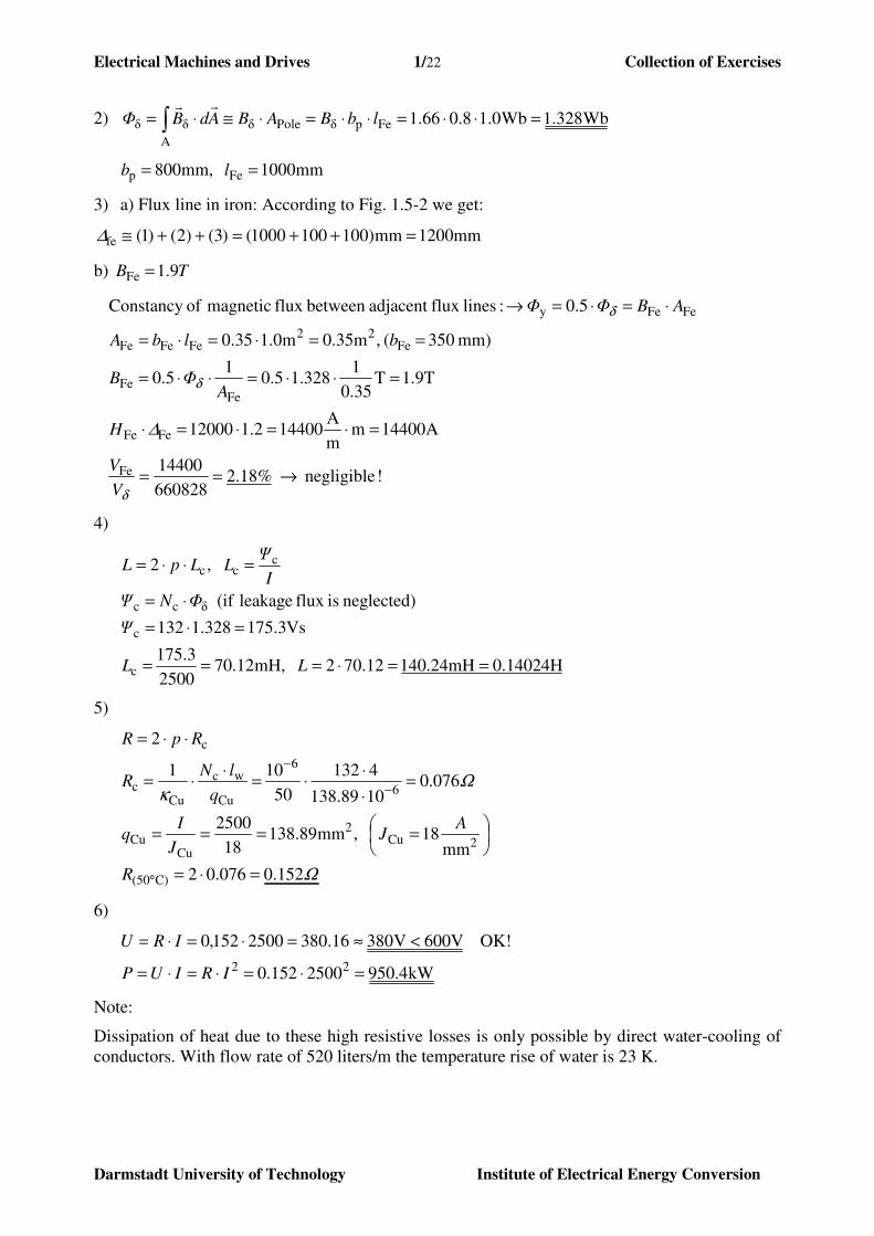
5) Due to the fact that the contour of rotor poles is not perfect the magnetic field in air gap has
field wave harmonics with ordinal number 3, 5 and 7. The values of their amplitudes are
listed below.
Fig. 1.6-1: Third flux density harmonic in air gap
05,0 08,0 15,01µp,
7µp,
1µp,
5µp,
1µp,
3µp,===
=
=
=
=
=
=
B
B
B
B
B
B
Calculate the values of the associated line-to-line induced voltages!
? ? ?1µi,
7µi,
1µi,
5µi,
1µi,
3µi,===
=
=
=
=
=
=
U
U
U
U
U
U
6) Calculate the r.m.s. value of voltage harmonics with respect to total r.m.s. voltage value,
using data of 5) !
Electrical Machines and Drives 1/24 Collection of Exercises
Darmstadt University of Technology Institute of Electrical Energy Conversion
Solution:
1) 42 460/500
67,16222 =⇒=
⋅=
⋅=⋅⇒⋅= p
n
fppnf
2) 1µp,p1µ
2== ⋅⋅⋅= BlΦ τ
π
Wb694,10,154,1728,12
1,54m m,728,122
2,2
p2
si
1µ
p
=⋅⋅⋅=
==⋅
⋅=
⋅
⋅=
=π
ππτ
Φ
ld
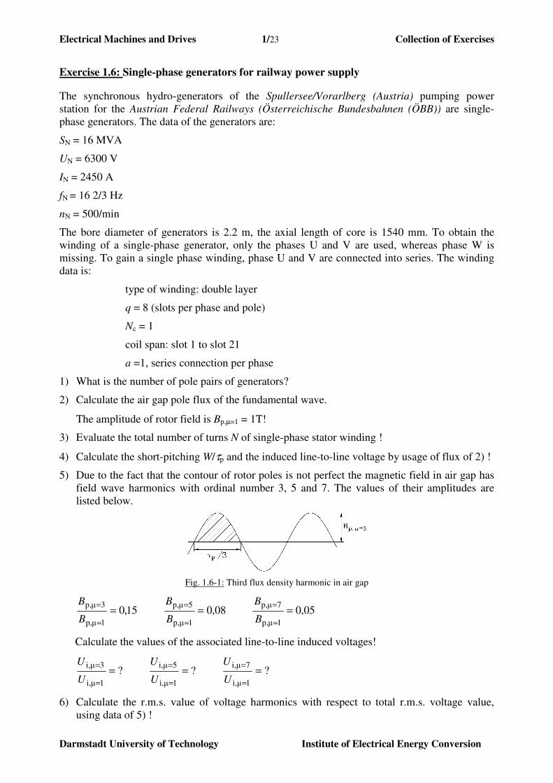
3) According to Fig. 1.6-2, we get for the single phase winding the total number of turns N:
Fig. 1.6-2: Generation of single phase winding out of three-phase winding scheme
643222321/184/2 =⋅==⇒=⋅⋅=⋅⋅= scs NNaNqpN
4)
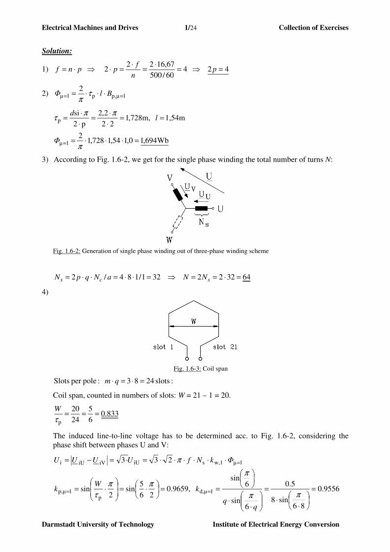
Fig. 1.6-3: Coil span
:slots 2483 :poleper Slots =⋅=⋅ qm
Coil span, counted in numbers of slots: W = 21 – 1 = 20.
833.06
5
24
20
p
===τ
W
The induced line-to-line voltage has to be determined acc. to Fig. 1.6-2, considering the
phase shift between phases U and V:
1µw,1siUiViUi 233 =⋅⋅⋅⋅⋅⋅=⋅=−= ΦkNfUUUU π
9556.0
86sin8
5.0
6sin
6sin
,9659.026
5sin
2sin 1µd,
p1µp, =
⋅⋅
=
⋅⋅
==
⋅=
⋅= ==
ππ
π
ππ
τ
kW
k
Electrical Machines and Drives 1/25 Collection of Exercises
Darmstadt University of Technology Institute of Electrical Energy Conversion
V6414694.1923.03266.1623
923.0
1µi,
1µd,1µp,1µw,
=⋅⋅⋅⋅⋅⋅=
=⋅=⇒
=
===
πU
kkk
5)
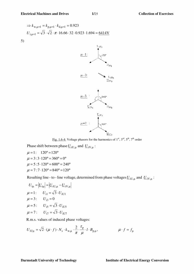
Fig. 1.6-4: Voltage phasors for the harmonics of 1st, 3
rd, 5
th, 7
th order
120 840 1207 :7
240 600 1205 :5
0 360 1203 :3
120 120 :1
: and phasebetween shift Phase µiV,µiU,
°=°=°⋅=
°=°=°⋅=
°=°=°⋅=
°=°=
µ
µ
µ
µ
UU
iU7i7
iU5i5
i3
iU1i1
µiV,µiU,iµiµ
µiV,µiU,
3 :7
3 :5
0 :3
3 :1
: and voltagesphase from determined voltage,line-to-line Resulting
UU
UU
U
UU
UUUU
UU
⋅==
⋅==
==
⋅==
−==
µ
µ
µ
µ
R.m.s. values of induced phase voltages:
µµp,p
µw,siUµ ,2
)(2 ffBlkNfU =⋅⋅⋅⋅⋅⋅⋅⋅⋅= µµ
τ
πµ
Electrical Machines and Drives 1/26 Collection of Exercises
Darmstadt University of Technology Institute of Electrical Energy Conversion
⋅
⋅⋅
⋅
=
⋅⋅=
kW
k
6sin
6sin
,2
sin µp,p
µd,πµ
πµ
π
τµ
p,1
µp,
w1
wµ
iU1
iUµµd,µp,µw,
B
B
k
k
U
Ukkk ⋅=⇒⋅=⇒
µ
µp,k
µd,k iU,1
µiU,
U
U
i,1
µi,
U
U
p,1
µp,
B
B
1 0.9659 0.9556 1 1 1
3 -0.707 0.64 -0.0735 0 0.15
5 0.259 0.194 0.0044 0.0044 0.08
7 0.259 -0.141 -0.0020 -0.0020 0.05
Due to the influence of short-pitching the voltage harmonics are much smaller than the field
harmonics.
6) Total harmonic distortion k:
00483,0
002,00044,01
002,00044,0
1
22
22
2
i1
i7
2
i1
i5
2
i1
i3
2
i1
i7
2
i1
i5
2
i1
i3
27
25
23
21
27
25
23
=++
+=
=
+
+
+
+
+
=+++
++=
U
U
U
U
U
U
U
U
U
U
U
U
UUUU
UUUk
iiii
iii
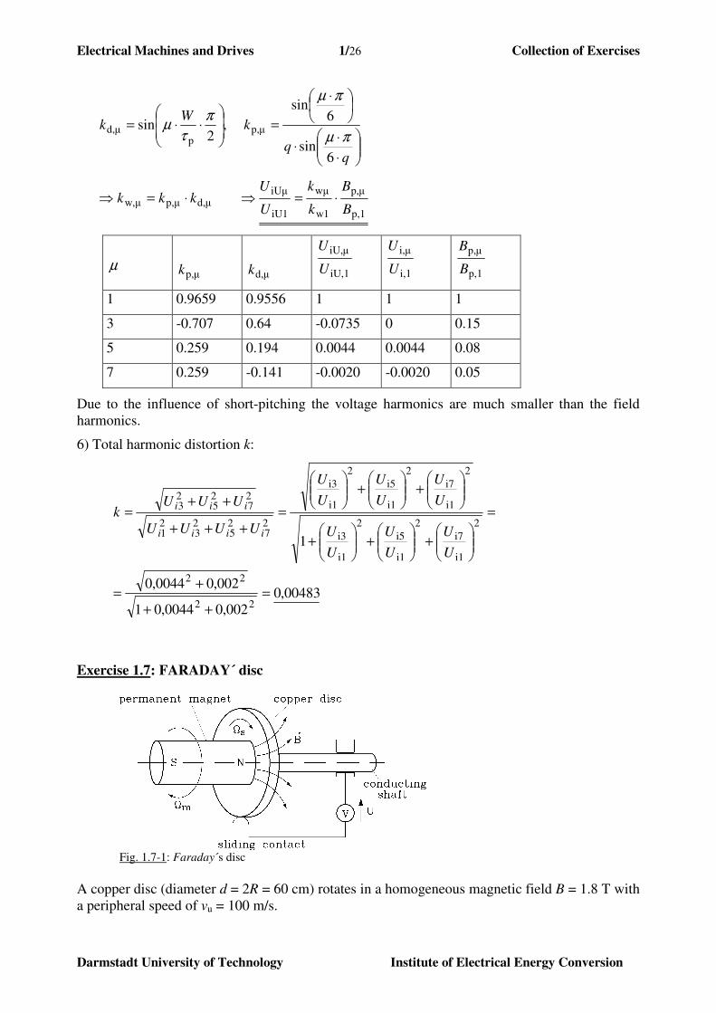
Exercise 1.7: FARADAY´ disc
Fig. 1.7-1: Faraday´s disc
A copper disc (diameter d = 2R = 60 cm) rotates in a homogeneous magnetic field B = 1.8 T with
a peripheral speed of vu = 100 m/s.
Electrical Machines and Drives 1/27 Collection of Exercises
Darmstadt University of Technology Institute of Electrical Energy Conversion
1) How big is the rotational speed n = Ωs/(2π) of the disc in 1/s and 1/min?
2) How big is the induced voltage between the disc centre and disc outer radius R?
3) The disk will be connected via 2 carbon brushes as sliding contacts, one at the disc centre
and one at the outer radius, with an external OHM’ resistance R = 1 Ω. The internal
resistance of the disc is neglected. The voltage drop of both brushes amounts to 2 V at
current flow. How big is the load current I ?
4) The friction losses of the disk (brush-, air-, bearing friction) amount to Pfr = 100 W. How
big is the for 3) necessary mechanical power Pm, which should be applied to the disk and
the corresponding mechanical torque M ?
Solution:
1) ndvu ⋅⋅= π ⇒ min/ 3183/ 536.0
100==
⋅=
⋅= s
d
vn u
ππ
100=uv m/s, 6.0=d m
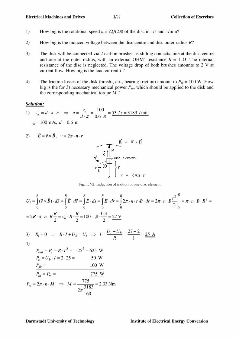
2) BvErrr
×= , rnv ⋅⋅= π2
Fig. 1.7-2: Induction of motion in one disc element
V 272
3,08,1100
222
222)( 2
0
2
00000
=⋅⋅=⋅⋅=⋅⋅⋅=
=⋅⋅⋅=⋅⋅=⋅⋅⋅⋅=⋅=⋅=⋅=⋅×= ∫∫∫∫∫
RBv
RBnR
RBnr
BndrBrndrEdsEsdEsdBvU
u
RRRRRR
i
π
πππrrrrr
3) 0≈iR ⇒ ib UUIR =+⋅ ⇒ A 251
227=
−=
−=
R
UUI bi
4)
W100
W50 252
W625251 22
=
=⋅=⋅=
=⋅=⋅==
fr
bb
eout
P
IUP
IRPP
W775 == min PP
MnPm ⋅⋅= π2 ⇒ Nm 33.2
60
31832
775==
πM
Electrical Machines and Drives 1/28 Collection of Exercises
Darmstadt University of Technology Institute of Electrical Energy Conversion
Exercise 1.8: Gearless synchronous wind generator
A synchronous generator with electrically excited rotor is directly coupled, without any gear, to a
wind turbine. It must therefore be designed for ultra low speed of only 15/min.
Generator data:
MW5,1N =P min
115N =n
902 =p m5si =d
mm145Fe =l 2=q
6
5
P
=τ
W 3C =N (number of turns per coil)
The generator is equipped with a three-phase, two-layer winding in star connection with short
pitched coils 6/5/ P =τW . All coils per phase are connected in series (a = 1).
1. Calculate number of turns per phase Ns !
2. Determine winding factor kw,ν for fundamental field wave ν = 1 !
3. How big is flux per pole Φ at an fundamental air gap field amplitude Bδ,ν=1=1,0 T ?
Determine induced no-load voltage per phase Ui,ph at rated speed !
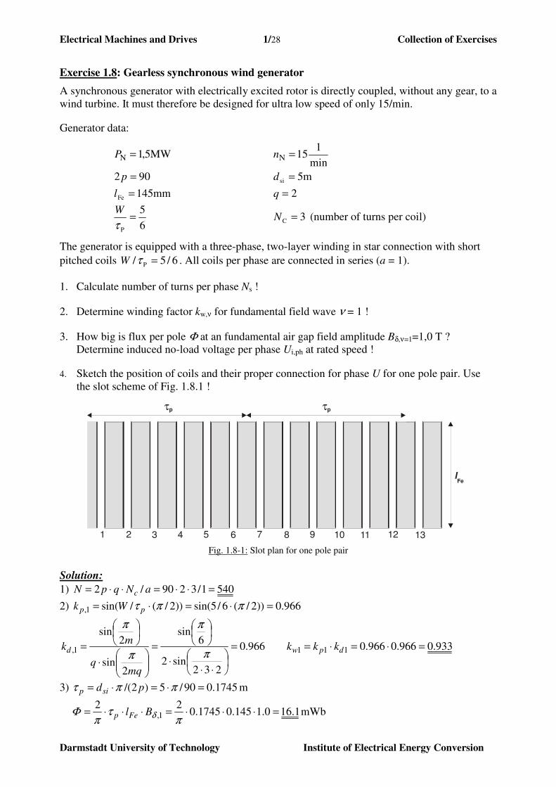
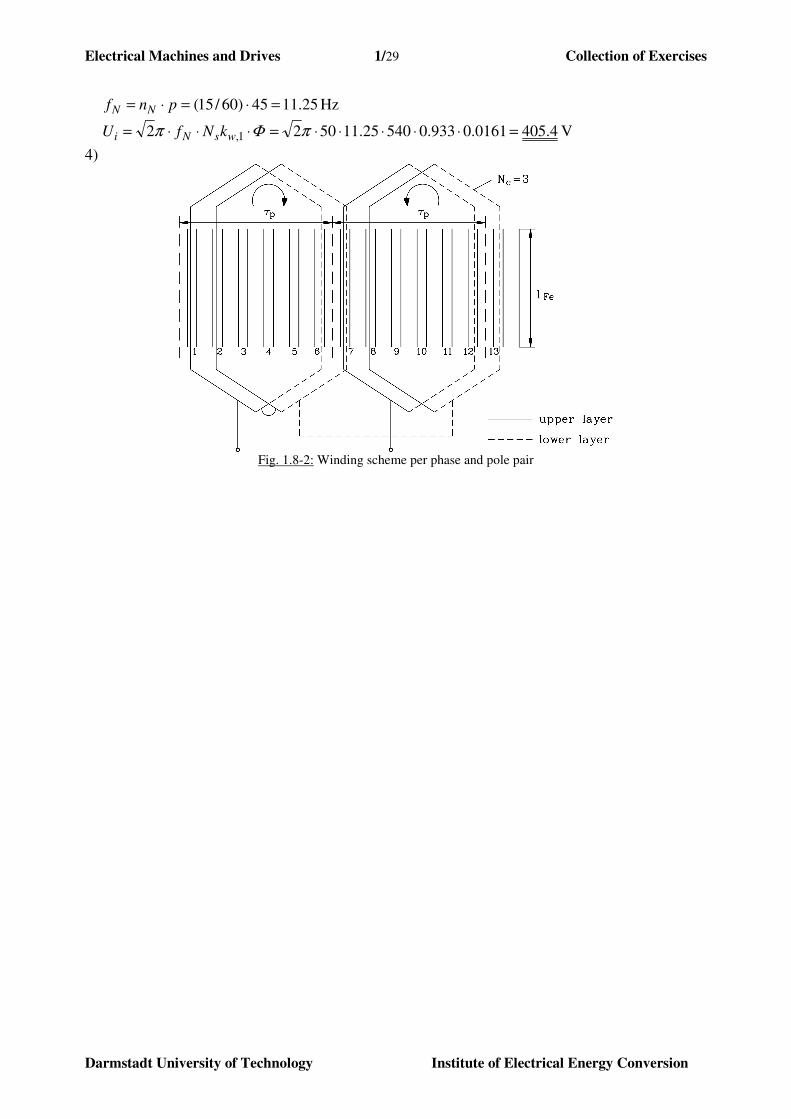
4. Sketch the position of coils and their proper connection for phase U for one pole pair. Use
the slot scheme of Fig. 1.8.1 !
1 2 3 4 5 6 7 8 9 10 11 12
τp τp
lFe
13
Fig. 1.8-1: Slot plan for one pole pair
Solution:
1) 5401/3290/2 =⋅⋅=⋅⋅= aNqpN c
2) 966.0))2/(6/5sin())2/(/sin(1, =⋅=⋅= ππτ pp Wk
933.0966.0966.0966.0
232sin2
6sin
2sin
2sin
1111, =⋅=⋅==
⋅⋅⋅
=
⋅
= dpwd kkk
mqq
mk
π
π
π
π
3) 1745.090/5)2/( =⋅=⋅= ππτ pdsip m
1.160.1145.01745.022
1, =⋅⋅⋅=⋅⋅⋅=π
τπ
Φ δBlFep mWb
Electrical Machines and Drives 1/29 Collection of Exercises
Darmstadt University of Technology Institute of Electrical Energy Conversion
25.1145)60/15( =⋅=⋅= pnf NN Hz
4.4050161.0933.054025.115022 1, =⋅⋅⋅⋅⋅=⋅⋅⋅= πΦπ wsNi kNfU V
4)
Fig. 1.8-2: Winding scheme per phase and pole pair