Embed Size (px)
Citation preview

C o n t r a c t N o . W-7k0$-eng-26
C B W C A L TECHNOLOGY D I V I S I O N
P l l o t P l an t Section
PREPM3ATSOTJ OF ENRICHING SALT 7LiF-233W4 FOR R P U E L I X G %HE MOLTEN SALT RWCTCR
Jchn M. Chandler S. E. B o l t *
MARCH 1969
“Reactor Division.
OAK RIBGE NATIONAL W O R A T O R Y Oak Ridge, Tennessee
operated by TJBIOM CAFBIDE CORPORATION
for the U. S. ATOMIC EFERGY COi?4MISSION
This repxi was prepared as an account of Government Hp.,nsored work. Neither the United States, nor the Commission, nor any person acting on tcluif of the Commission:
A. Malies any warranty or representation, expressed Or Impl id , with respect tu the accu- racy, completeness, or usefuiness of the information contained in th ip report, 02‘ that the use of any information, apparatus, method, o r process disclosed in this report illay not infringe privately owned rights; or
B. Assumes any llabLlItlep with respzct tu the use of. or for damage6 reSulting from the use of m y idormation, apparstua, method, UT procese disclosed in this report.
AB used in the a h v e , “person acting on behalf of the Cornmiasion” includes .my e=- ployee or contractor of the Commission. or employec of mch contractor, to the extent that such employee or contractor of the Comnfssior., or employee of such contractm prepnres, dieleminates, or provides acccis ta, any information pursuant to ius rrnplogment or cotztract with the Commission, or his employment uitk suck contractor.

. ... ... ....
iii
1.
2.
? -2 *
14 *
5‘
Abstract * . . . . . 0 . . 0 0 4 * . 6 . . * . 0 e . . . . . . . 4
Lntroduction . . . . . . . . . . . . . . . . . . . . . . . . .
231 Considerations for Substituting -"U in the MSRE .......
2.1 Nuclear Characteristics of the 233 U System .......
2.2 Chemistry of the Circulating Fuel
2.3 Fuel Preparation by Remote Means .
Process Development . . . . . . . . . .
a.1 High-Temperature, One-Step Process
3.2 Low-Temperature, T%o-Step Process
Description of SaPt Production Facility
4.1
4. 2
4.3
1.4 . 4
Description of the TURF . . . . .
4.1.1 Cell G . . . . . . . . . .
4.1.2 Radioactive Hot DraLn - Hot (RHD-HOC) . . . . . . . . .
4.1.3 Cell Ventilation . . . . .
4.1.4 Shielding . . . . . . . . .
4.1.5 Manipulators . . . . . . .
Process Flowsheets . . . . . . . .
lc.2.1 High-Temperature Process .
4.2.2 Low-Temperature Process . .
Process Equipment . . . . . . . .
4.3.1 Becanning Station . . . . .
4.3.2 Reaction Vessel . . . . . .
4.3.3 Salt Storage and Transfer Vessel ........
4.3.'c- Shipping Containers ...............
4.3.5 Scrubbers ....................
4.3.6 Miscellaneo~Js Equipment .............
Operating Procedures ..................
4 4 0 . . 0 4 4 . . 4
0 . . . 0 e 4 4 4 4.
4 4 0. 4 0 . . * 0.
4 4 4 4 4 4 4 6 4 4 4
4. 4 4 4. 4 0 0 . .
4 4 4 4 .s . . . 0 4
4 4 0. 0 4 4 4 4 4 4
4 4 . . 4 0 4 4 4 4 4
Off-Gas System . 4 4 4 4 6 4 0 . . 4
0 0 . . 4 4 . . 4 0 4
4 4 0 0 0 4 4 4 . . 4
4 4 . . 4 6 4. 4 4 4
4 4 4 4 4 4 4 4 4 4 4
. . 4 4 . . 4 4 4 4 4
4 0. 4 4 4 . . . 4.
4 4 4 4 4 4 4 4 4 4.
. . . 4 . . 4 0 . . 4
0 0 . . . 0 4 4 4 4 4
Cold Rus with Depleted Uranium ................
5.1 Preoperational Act-ivities ...............
5.2 Mechanical Operations .................
Page
i
E
8
9
9
10
11
11
I.3
15
J-9
19
22
22
27
31
36
36
36
36
iv
6.1
6.2
6.3 6.4
6.5 6.6
6.7 6.8
6.9
6.1~ 6.11
Feed Materials e e e a e s e o e e e e e e e e e e
Radiation Levels cf the Oxide Feed c e D e c e o a
Oxide Feed MaterEal Handling o c S 0 o . D e a e e
Reduction of Uranium Oxide s a 0 o o e o 0 e o e a
Hydrofluorination of UO2 e a 6 s e a 6 e e a e e B
Formation of the Eutectic Salt e 8 e e * e s a G .
PurEfication cf the Eutectic Salt c e D s . o 0 o
Transfer of the Eutectic Salt a S o o G I 0 o . 0
Container Disassembly and PreparatLon for Shipment
Transfer of 7LiF-233 IIF4 Salt Product to the MSRE c
Material Balance S a o a = 0 D c e e e e o e * e o
7- i%aintenance Engineering . a
7-E Spare Parts B . e a D
7.2 Redundant Fittings e a
7.3 Tools and Work Tables
7.4 Maintenance Procedures
8. Conclusions 0 0 e e 0 e . e
9. Acknowledgments a 0 D e D D
38
42
42
44 44 47 50
53 55 60 62 62 66
67 67 68 68
69
69
71
71
E
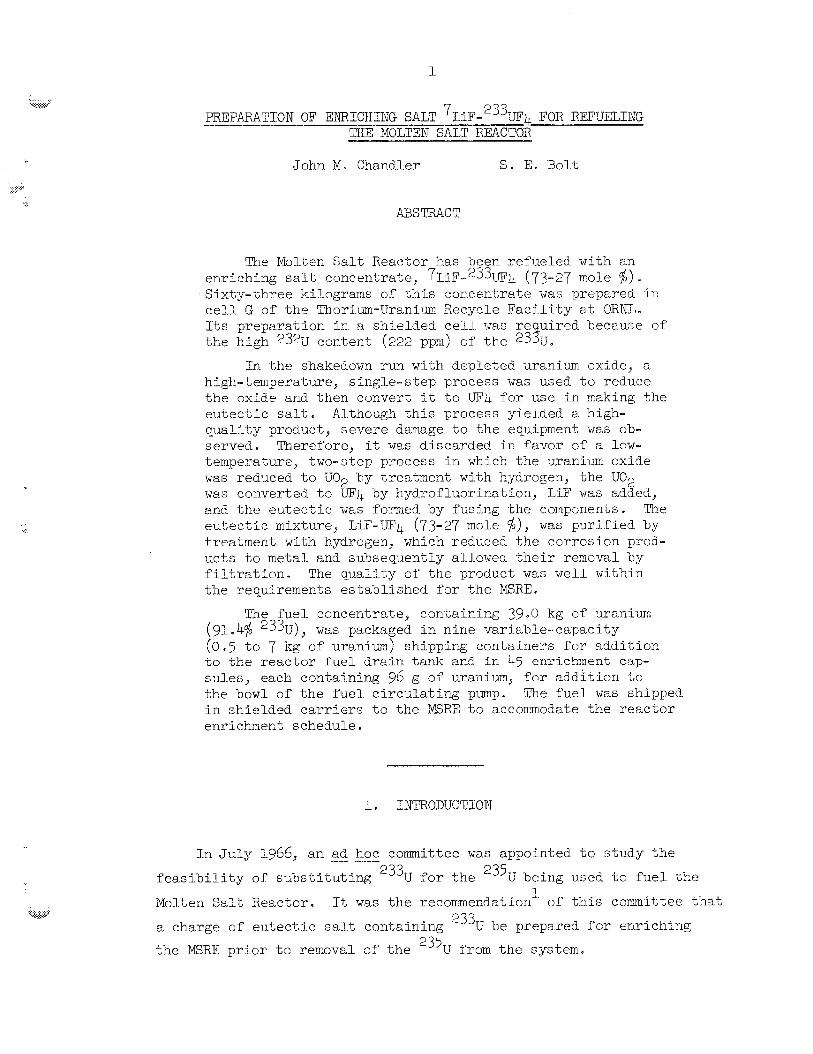
1
John M. Chandler S . E. Bolt
The Molten S a l t Weackor has been refueled wlth en enriching sal t concentratc, 7LiF-'33W4 (73-27 mole $> e
Sixty-%hree kiLograme of t h i s concentrate w a s prepared ir: c e l l G of t h e Thorim-Uranium Recycle F a c i l i t y a t ORNL. lets preparacion rEn a, shielded cell was r e u i red because of t he high 2% content (222 ppm) of t h e e3%Je
In the shekedown run with de-pletea araniwn oxide, a high-temperatue7 s ingle-s tep process w a s used t o redllce t h e oxide 2nd then convert it t o UT4 for use i n making t h e e u t e c t i c sa l t . Although this process yielded a high- qua l i sy product, severe damage t o the equipment w a s ob- served. Therefore, it w a s discarded i c favor of a bow- temperature, two-step process i n whick. t he -araiiim oxide was red-xed 'eo IJ02 by Lreatrnent with kydrogeii, t he U02 w a s converted t o LF4 by hydrofbuorination, LiF w a s added, and t h e e u t e c t i c w a s Formed by f u s h g the components. "he eu+uectic mixture, LiF-UP4 (43-27 mole $j)7 w a s pu r i f i ed by treatmect with hydrogel?, which redwed t h e c o r m s ion proa- uc ts t o metal and subsequently allowe6 t h e i r rernoval by f i l t r s t i o n . The qua l i t y cf the product w a s w e l l wi thin the requiremects es tab l i shed f o r t h e PEBE.
(91 k% '33U) (0.5 t o 9 lig of' uran2rz.n) shipping co i t a ine r s f o r addi t ion to t h e reactor f u e l d ra in tank and i n 45 enrichment cip- su les , each containing 96 g of uranium, f o r addi t ion t c the bowl of t h e fuel c i r cu la t ing pump. The f u e l w a s shipped i n shielded c a r r l e r s t o the E R E t o acconlmodate the r eac to r enrichment schedule.
The f u e l concentrate, conxTning 39.0 kg of uranium w a s packaged i n nine var iable- capaci ty
I n J u l y 1966, an -___ ad hoc committee w a s appointed t o study t h e
f e a s i b i l i t y of s u b s t i t u t i n g 233U f o r t h e 235U being used t o f u e l t h e
Molten Salt; Reactor. It w a s t h e recorrmecdaticn of' t h i s committee tha%
a charge of eurLect,ic salt containing
t h e MSRE p r i o r to renova1 0:' t h e 235U from t h e system.
E
233 U be prepared for enriching
2
A s ingle-s tep process, i n which the f u e l concentrate could be
and LiF, i n a. s i n g l e r eac t ion vesse l prepared d i r e c t l y from 233UC9
located i n a 'not c e l l , w a s comidered t o be the simplest and m o s t
economical approach Eio logica l sh ie ld ing woxld he required because
of t h e 'nigh 232U content (222 ppm) of t h e 233U feed material.
3
The required quant i ty and qua l i ty of t h e enriching concentrate
w i l l permit operat ion of t h e MSRE at full power f o r a t least one year.
T ~ i s r epor t sumar i zes I;he preliminary phases of t h e wcrk - developKent, design,and construct ion - as well as t h e a c t u a l operat ion
of t h e process used t o prepare t h e 7LiF*'33W4 (73-27 mole $1 e u t e c t i c
sa l t
2- CONSIDERATIONS FOR SUBSTITUTING 233U IN THE ISWE
The subs t i t u t ion of 233U f o r 235LJ i n the YfRE had tc be considered 233, frcm th ree s tandpoints :
system, (2) t he chexistry of the c i r c u l a t i n g fuel, and ( 3 ) t h e preparat ion
and handling of a e33U salt containing
(1) t h e nuclear c h a r a c t e r i s t i c s sf t h e
23eu
2.1 Nuclear Charac te r i s t ics of t h e 233U System
A 1 assessment2 of t h e operat ion c;f t he Molten Salt Reactor with
233U has ind ica ted t h a t t he following could be lezrned by subs t i tc t ing
t h e new fuel charge:
(1) C r i t i c a l loadings would provide a check on t h e ava-ilable
nuclear da t a cn 233U f o r pred ic t ing c r i t i c a l condi t ions i n a
r eac to r with a neutron energy spectrum similar t o t'nat of the
proposed noaten sal t breeder r eac to r (VEBR).
&leasuremeat of 234u-to-233, atom Pat ios over a period cf sub-
s t a n t i a l burnup might f u r t h e r evaluate ava i l ab le nuclear da ta
and ca l cu la t iona l nethods.
(21
(3) In t e re s t ing d i f fe recces would be observed i n t h e d p a q i c s of
t h e r eac to r because of tlre smaller f r a c t i o n of delayed neutrons

3
ava i l ab le from 233U f i s s i o n .
t he E R E would tend t o confirm t e i t a t ive conclusions regwcling
t h e dynamics of t he M5BR.
Knowledge of t he f i s s i o n product y i e lds f o r 233U1 es compared
with those for "'u, would provide a means of more pos i t i ve ly
iden t i fy ing the r e a c t i v i t y t r ans i en t s t h a t follow changes ir:
power l eve l s .
S tab le operat ion with 233U i n
Changes i n o ther nuclear cha rac t e r i s t i c s , such as temperature
coef f ic ien ts , neukron l i fe t ime, and control. red worth, would
be observed e
2.2 Chemistry of t h e Ci rcu la t ing Fuel
The uranium concentration i n the r eac t c r t r i l l be reduced t o 0 .2
mole $; however, s ign i f i can t increase i n UF concentraLion or precr ip~-
t a t i o n of urar,im o r UO, i s expected. Most of the proper t ies of %e new 3
c f u e l charge w i l l be very s i m i l a r t o those of the 235U f u e l . Mo change
i s expected i n t h e conpa t ib i l i t y of t h e fu .e l with the graphi te a,:id the
Hastel loy N.
2 . 3 Fuel Preparation by Wenote Means
A s t rong incent ive cxis ts €or develcping an eccmomieal method f o r
reprocessing irradiated f u e l f o r reuse i n ;2 power r eac to r . T2;e high
232U content of t h e 233U w i l l make remote processing of' a 233U f u e l charge
mandatcry. Therefore, it i s des i r ab le t o prove t h e f e a s i b i l i t y of a
simple, d i r e c t fuel recycle process without t h e necess i ty of' h igh-level
decontarnination; t h i s would emphasize the advantages of t h e fi?el
preparat ion f o r molten s a l t reac tors .
The preparat ion of t h e enriching salt , 7 L i F * g 3 3 , 4 (73-27 xole '$>?
7 Prom LiF and '33U02 by z d i rec t high-temperature, one-step process, wac 3 -?
inves t iga ted4 i n t h e laborakory and Pound t o y i e ld 8 s a t i s f a c t o r y p rodmt =
4
Hcwever, during t h e cold run i n Euilding 7930, the high temperatures
2ecessary for t h i s process were f'ound t o promote corrosion of t h e eqGip-
ment; thus, an a l t e r n a t i v e method - a low-temperatu.re, two-step process - w a s adopted. These processes a r e discussed i n d e t a i l i n Sec t . 4.2.
3 .1 High-Temperature, One-Step Process
The chemical procedures t h a t were developed f o r t h e production of
t he fuel concentrate were similar t o those used i n t h e rou t ine prepara-
t i o n oP UF4 from cxides.
0;' a v e r t i c a l l y mounted, c y l i n d r i c a l r eac t ion vesse l r a t h e r than t r ays
o r fluidized-bed reac tc rs , (2) t he addi t ion of LiF t o t h e i n i t i a l charge
of material, and ( 3 ) t h e operat ion of t h e process a t temperattu-es
s u f f i c i e n t t o maintain t h e LiF i n i t s molte3 state.
Necessary modifications included: (1) t h e use
La-bo-ratory-scale experiments w e r e conduc6,ed by the Reactor Chemistry
Division ec gain k f o m a t i o n a b c x t t he rates a t which t h e reac t ions would
occur and a l s o t o exmine poss ib le process con t ro l techniques. The
reac t ions inves t iga ted were:
S in te r ing:
Reduction:
WyiirofEuorinatLcn: M2-m sparge a t 930-55O"C uc* t- 4HF - uF4 + 2H20
b F +H2 -I@ i- 2pTp Reduction of impuri t ies : Hydrogen sparge at 700°C
2 I n the reduct ion s t e p t h e progress of t h e r eac t ion could be follcwec?
by observing t h e generatic?? of water vapor i n t h e system. The temperat-Jre
of t h e gas eff1ue:it increased markedly during t h i s period e
DurrEng t h e kydrofluar inat ion treatment, hydrogen, along with anhy-
droys E?, was admitted t o t h e reac t ion vesse l to cont ro l t h e corrosion
of the vesse l and a lso t o ensme t h e complete reauct ion of UO t o U02. The conversion s t e p CP t h e process w a s c a r r i ed out a t temperatures
s u f f i c i e n t l y high t o keep all of the LiP i n so lu t ion .
3
Thus, as W4 w a s
5
produced, the liquidus temperature of the fluoride components decreased
from &kg to 4gO"C, the mel3ing point of the eutectic mixture.
equipment use$ in the development runs, $he Liquidus temperature could
be measured and the Up concentration could be determine& by comparison
with the phase diagram. K final treatment of the melt wikh hydrogen at qOO"€! reduced the concentyation of nickel and iron to acceptably How
levels e
21 the
4
Upon successful comptetion of the laboratory-scale experiment, z
cold run, using equipment that more closely resembled the production
equipment, was conducted by the Reactor Chemistry Division. 'This rw-
served to further confirm the feasibility of' the one-step process and
also to train key personnel -Tor the production operations at the
Thorium-Uranium Recycle Facility (TURF)
3-22 Low-Temperatce, Two-step Process
As an alternative to the high-temperature method, a two-step, low-temperature process was evaluated in a labsratoaay experiment and
subsequently used in the sa l t production ruis.
is sin;ilar to that used to produce the original fuel salt for the E R E ,
the temperatures ere generally much lower, and the LIP is not added until the conversion of' the oxide to the fluoride has been completed by
hydrofluorination.
I n this process, which
4. DESCRIWIQM OF SALT PRODUCTION FACILITY
The processing equipment was installed in cell G of the 71uRp, vhich
is located in the Melton Valley area of Oak Ridge ITational Laboratory.
This facility contains shielded ce l l s and process supporting systems
to permit remote fuel reprocessing.
4
4-1 Description of the TURF
The TURP, Building 7930, was constructed at Oak Ridge Rational Laboratory to help develop and demonstrate economical remote methods
for reprocessing irradiated thorium-based fuel and for refabricating
the purified fertile and fissile material into fuel suitable for reuse
in a power reactor. The m e of shielding and remote fzbricaticn methods
will permit the use cf simplified processes yielding only modest decor,-
taminatien factors.
The W has sufficient space to accomodate equipment for process- ing and fabricating 'uwo types of fuel assemblies simultaneously. T'e
facility is divided into four nator &reas:
tc, but isolated from, areas that contairL radioactivity, ('2) an operating
area with a development laboratory, chemical makeup area, and equigment
rooms for service equipnent, ( 3 ) a malctenznce operating area with ser- vice areas for receiving and storing spent fuels, and (4) a cell complex
containing seven hot cells (six shielded and one mshielded) e
(E) an o f f i c e area aiijacent
Included in the f a c i l i t y arc the services, ventilation systems,
crane and manipulator systems, viewing systems, and liquid and gaseous
waste disposal systems necessary to support fuel reprocessing.
4.1.1 Cell G
The 233U fuel charge fer the KWE was prepared in cell G . The
interior of this cell is 20 ft wide, 16 ft longJand 33 ft 5igh .
flser waE installed to elevate the process equipment so that the thmugh-
wall naster-slave manipulators could be used and rnaximm advantage could
b e taken or" the viewing capabilities of the shielding windows. miis
decreased the effective height of the cell to 22 ft, which, in reality,
was further reduced tc 14 ft of effective headroom because of the in- cell electremechanical manipulator system space requirements at the top
of the cell. The walls, ceiling, and floor of the cell are lined with
stainless steel. Six cell operating modules (Fig. 1) are built into t k walls of the cell; four of these are equipped with viewing windows, and
two have window forns that are filled with removable shielding. There
are more than 100 penetrations into the cell for process services - many more than are required for the salt preparatior:.
lation system nomally maintains a pl-essure of -5 in. H 0 and a flow of 1033 cfm of air through the c e l l ; the vessel off-gas system removes
A fa lse
The cell venti-
2
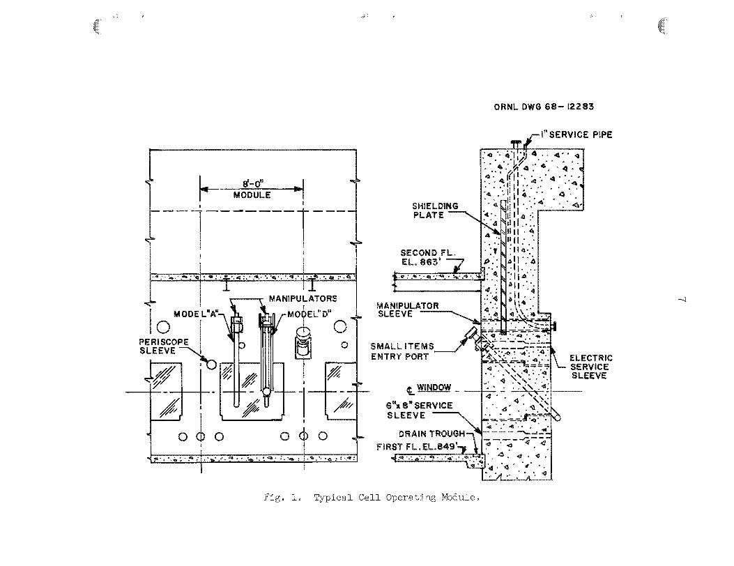
7

8
25 cfm of a i r from the c e l l and process vessels and roa tes it t o a
system t h a t i s maintained a t a pressure of -17 i n . H 0. A s m a l l e n t r y
por t permits introduct ion of small too l s a d miscellaneous items through
a glove box and an a i r lock. roof of t he c e l l contains a hatch with
a 10- by 6-ft opening t h e t i s sealed and shielded. The hatch Frovides
access t o t h e c e l l with the 50-ton bui lding crane. Eight master-slave
manipulators were i n s t a l l e d i n t he c e l l : four Central Research Nodel A
and four Central Research Model D un i t s . A Program and Remote System
Model 3000 electromechanical manipulator system i s moznted on ra i l s -Lo
give complete coverage of t he c e l l .
2
4.1.2 Radioactive ~ o t k a i n - ~ o t ~ f f - ~ a s System (RED-HOG)
The rad ioac t ive hot drain--hot off-gas system i s a combination by-
product waste col-lection system and v e s s e l off-gas system. It has i n l e t
cocnections i n the hot cells and a t vzrious poin ts throughout t h e f a c i l i t y .
The network of s t a i n l e s s s t e e l piping i s designed to han15le gas
and l i c p i d i n concurreiit flow. Liquid waste i s separated from the off-
gas and i s co l lec ted i n tank B-2-T i n the belcw-grade and shielded waste
tank p i t . Tae gaseous stream flows through a bank o-C absolute f i l t e r s
and then into t h e c e l l exhaust sys tex located upstream of t h e f i l t e r
units f o r t h a t system. The l iquid wastes may be pumped e i t h e r i n t o t h e
Melton Valley waste system o r into c e l l G f o r recovery of valuable
mater ia l s
%wc connecti.ons from c e l l G to t h e HQG system were made f o r t he
sa l t preparet ion process. One connection was made t o the capsule d r i l l -
ing stazion i~ order 'io collect t h e p a r t i c u l a t e matter r e s u l t i n g fron;
the d r i l l i n g eperat ion. The other was made t o a multipurpose manifold
s t a t i o n . With the HOG system pressure control led a t -17 i n . H 0, t he
f l o ' ~ ~ of air from the c e l l was adjusted t o 25 cfm by a m a ~ m l l y operated
valve. The gaseous e f f l u e c t fl-om the process scrubbing system vas dis-
charged i c t o t h i s manifold s t a t ion , thereby e n s u i n g dilution, i n the
case of hyclrsger,, t o less than the explosive l i m i t .
scrubber discharge, the manifold s t a t i o n served the i n - c e l l t i t r a t i o n
s t a t ion , the sampling s t a t ion , the can-opening bcx, t h e scru-bber systen
2
I n addi t ion t o t h e

and sink l i q u i d drains , and a l l of t h e process vesse ls . Some of t hese
connecticns were made t o the manlifold s t a t i o n on t h e c e l l s ide of t h e
manual flow regula t ing valve, where the pressure was -5 i n . H 0; sene
were made 03 %he HOG sys ten s i d e of t h e valve, where t h e pressure was
-15 i n . H,?O. The loca t ion of each connectLon depenaed upon t h e pressure
requirement for t h a t p a r t i c u l a r use e
2
r L
4.1.3 Cell Vent i la t ion
Approximately 1033 cfrn of a i r en ters c e l l 6; from the ceLl G pump
room via. a series of filters, a f i r e danper, a back-flow preveiiter, an6
a c e l l pressure c c x t r o l valve. It discharge= i n t o t h e cell from dif-
fusers t h a t are mounted on t h e c e l l ce i l i ng arid then flows through
roughing f i l t e r s located a t t h e fa lse floor (end a l s o a t t h e c e l l floor
l e v e l ) i n t o t h e c e l l v e n t i l a t i o n system macLEold i n the north valve
pit. The f l o w i s cont rc l led by a maRmlly loaded valve i n t h e exhaus;
duct . The exhaust 2s routed t o t h e f i l t e r pic , where it passes thrCJugh
two sets of f i l t e r s i n s e r i e s ; from there , it passes tlirongh a 32-in. d c c t
t o t h e c e n t r i f - g a l blowers and i n t o t h e 250-ft HFIR s t ack fcr disFersPon
i n t o t h e atmosphere. The c o i t r o l s or, zhe v e n t i l a t i o n system m a k i t a i r _
a pressure of -5 i n . H 0 i n t h e cell under nom-a1 condi t ions. Pressures
as low as -20 i n . H 6 o r as high as -1 i n . %E 0 car, be maintain& i n t h e
c e l l under c e r t a i n emergency condi t ions. Only a f a i l u r e of' a l l emer-
gency systems w o u l d al low the pressure i n the cell to rise above -4.5 i n . H20.
2
2 2
4.1.4 Shielding
The sh ie ld ing of t h e TURF I s designed
operat ion with rad ioac t ive material having
in scch a manner tha t , durEng
an i n t e n s i t y of l C . r / h r , 5 -
the penet ra t ing dose rates i n normally occupied areas are no g rea t e r than
0.25 mrem/hr, with s m a l l ho t spots no g rea t e r than 2.5 m r e m / h r . Dose
rates g r e a t e r than this are permitted i n l imited-access areas and €or
short-term, non-routine operat ions.

10
To s a t i s f y the allowable design r a d i a t i o n leve ls , t he operating
c e l l s have 5-1/2-ft-thick walls of noma1 concrete up 'eo a height of
11 ft, b1/2 f t of normal concrete f o r t he renaining port ions of t he
v e r t i c a l walls, and 5- f t - th ick concrete on the roof . This amount of
b io logica l shielding w a s more than adequate t o reduce exposrrre dose
r a t e s t o < 0.1 mr/hr.
The windows a r e e s s e n t l a l l y equivalent, i n sh ie ld ing thickness and
i n t h e i r a t tenuat ion of penetrat ing rad ia t ion , to t he concrete walls
i n which they a r e i n s t a l l e d . Each window cons is t s of two major assem-
b l i e s : t he seal glass t h a t i s removable from ins ide the c e l l , and t he
tank u n i t t h a t i s removable from the operating face of t h e c e l l . h c h
window i s a composite u n i t consis t ing of 9 i n . of g l a s s and 58 i n . ' o f
zinc bromide so lu t ion ; it is wel l sealed t o mintmfze leakage of a i r
around i t s periphery.
4 a 1 e 5 bihnipulators
A Programmed and Remote Systems Model 3900 Manipulator System i s
inska l led on a set of' rails ir_ c e l l G . The tube hoisc on this manip-
ulator has a v e r t i c a l t r a v e l cf l3-1/2 f t and a l i f t i n g capaci ty of l~3OO
lb.
t he tube hoist, provides complete nanipulator coverage sf t he cell down
t o the f a l s e f l o o r . This mit provides a l l the motions of t h e hurnan
a r m , p lus wrist extension and ccnttnuous r o t a t i o n a t t h e mist and a t
the shoulder. A g r i p force cf 200 lb can be exerted with t h e Pingers.
The hand i s remotely removable and can be replaced by a hook f i x t u r e o r
an iKpaet wrench.
The t r o l l e y and bridge t r ave l , along with the v e r t i c a l t r a v e l of
One C e r t r a l Research Model A master-slave manipulator and one
Model B master-slave manipulator a r e i n s t a l l e d a t each of the four
viewing windows i n c e l l 6; .
niaximux l i f t cepabilities of 25 lb and 100 lb, respec t ive ly .
The Model A and the Model D manipulator have
These master-zlave units were i n s t a l l e d t o operate valves, t o make
and break tubing disconnects and e l e c t r i c a l and thermocouple disconnects,
and t o conduct t he hand operations required in the process. Conventional
hand too l s were modified f o r use w L t h these manipulators.

The PaR electromechanical manipulator was ins5a l led r~c perf'crm t h e
heavy-duty maintenance, to convey heavy asseribPies around the c e l l , t o
reach sone p a r t s of t he c e l l thak were not access ib le t o t h e master-
s lave manipulators, and t o provide a " th l rd r t hand to sin-obify c e r t a i n
operat ions.
4.2 Process Floveheets
Two processes were developed f o r t h e prepare t ioc c:' tne fuel
concentrate: ( I ) a high-temperature process, and (2) a low-temperatire
process.
run whec it became evident t h a t t he o r i g i n a l process caused severe
corros-ioc of t h e r eac t ion vesse l .
The second process w e s a.dopted a f t e r conclusion of t h e ccld
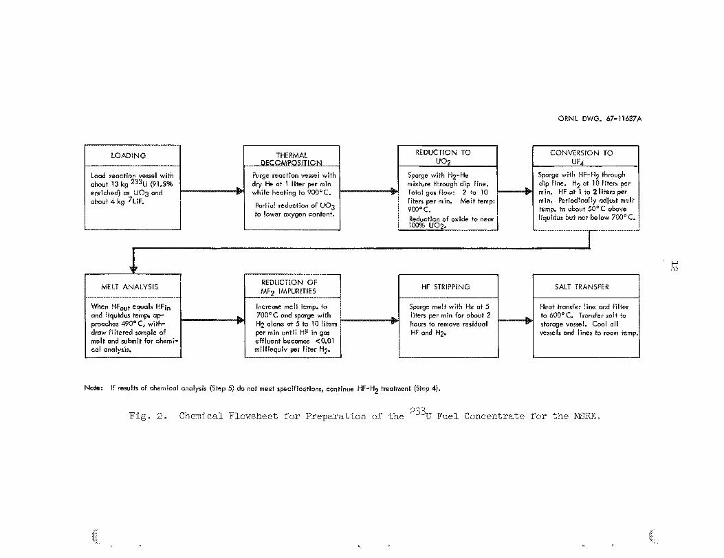
4.2.1 High-Temperature Prccess
The chexical Plowsheet €or as shown ir_ block forin (Fig. 2)
t h e one-step, high-temperature ~ m c e s s
includes the Pollowing rnajcr s teps :
( E ) Pa rk ja l reduct ion of t h e uran5.m oxiaeJ233V0 by t h e m e l 3?
means
(2) Furthey reduction t o UO by hydrogen t reatment .
( 3 )
2
Conversion of t he oxide t o E? by hydrcf luorinat ion and ccn- 4 cur ren t dissolution of t he In t h e rLoltear LiF t o form t.he 4 e u t e c t i c mixture
(4) F i n a l pu r i f i ca t ion of t h e eu tec t i c mixture by treatment with
high-puri ty hydrogen.
LiF was combined with the 233U0 7 The i n the i n i t i a l charge -to t he 3
r eac t ion vesee l . The reduct ion process w a s then conducted a t texpera-
tures in excess of 845°C (EiP m e l t i n g po in t ) so t h a t t h e oxide p a r t i c l e e
were suspended i n the n;olten f luo r ide . The molten LiF served t o keep
the oxide p a r t i c l e s w e t , thus reducing t h e p o s s i b i l i t y of entrainment
of p a r t i c u l a t e matter i n t h e e f f luen t gas stream.
fluorination Etep, t h e progress of the r eac t ion was estimated by
determining t h e l iqu idus temperature of t h e molten mater ia l , and ";hen
During t h e h y d ~ o -
Portid reduction of UQg
MELT ANALYSIS HF STRlPPlNG SALT TRANSFER
Note: If results of chemical cmdysis (Steep 5) d 0 net meet spcifications, continue HF-H+J treatment (Steep 4Js
Fig. 2. Chemical Flowsheet i"or Preparation of" the 233 U Fuel Concentrate -for the b4SRE.
P E

.. . . .. .,.,. >;.% &.%,
t h e furnace temperature con t ro l l e r w a s adjusted t o approximately 5 0 ° C
above t h i s values Frequent t i t r a t i o n s of t he r eac t ion vessel e f f luen t
gas stream yielded valuable inforna t ion on t h e progress of t he conver-
s ion of t h e oxide t o -%e f luo r ide s ince t h e u t i l i z a t i o n of E? remained
qu i t e high and near ly constant u n t i l t h e conversion w a s completed.
Chemical analyses of f i l t e r e d samples of t h e nzeLt were made t o
determine whether t h e f i n a l process - $he p c i f i c a t i o n cf the product
by hydrogen sparging - Ehould be i n i t i a t e d o r whether t h e kydrofluorfn-
a t i o n process should be continued e
4.2.2 Low-Texperature Process
The low-temperature process ( s e e Fig. 3 ) w a s used t o prcduce t h e
f u e l concentrate ' It d i f f e r s i n only one rrajor respect from t h a t used
i n the production of t he o r i g i n a l 235U-bear5ng enriching s a l t f o r ",he
E R E . I n t h e earlier process, t h e s t a r t i n g material w a s W4; i n the
low-temperature prccess, t h e s t a r t i n g inateriel i s UO The oxide i s
d iges ted a t 550°C and then reduced t o UO, by treatment wi-ch hydrogen
a t temperatures ranging from 4 0 t o 550°C. Helium i s used as a d i luen t
gas during the reducLion s t e p until t h e major por t ion of t h e exct'lermic
r eac t ion i s conpleted. The oxide i s then conver-f;ea t o W by hjrdro-
f luo r ina t ion a t temperasures ranging f r o m ~ Q O t o 630"~ and a t MF ( i n
hydrogen) concentrations varying from 5 t o 407%. process iravoive mixing arid f'using the f luo r ide salts, contaming with
3' I i
4
The f i n a l s teps of' t h e
and hydrogen t o remcve r e s i d u a l oxides and corrosion product im-
p u r i t i e s , acd f i l t e r i n g the molten s a l t d w h g i t s t r a n s f e r t o t h e
s torage coritainers a
The reduct ion and eonverslon processes were monitored by a therrno-
couple a r r a y t h a t w a s i n se r t ed i n t o t h e powder i n t h e r eac t ion vessel
and by measurernelzts of hydrogen u t i l i z a t i o n during the reduct ion s t e p
and of HF u t i l i z a t i o n dar ing the conversion s t ep .
t e r e d samples of t h e m e l t were withdrawn f o r oxide, petrographic, and
metal impurity analyses.
Unfi l te red and f l l -

14
L
-13e2 kg 88 as uo3
HEAT TREAT U03P
uog - 810 uo2 -UF
3 TO 5 hr BlGESTlON AT 558°C; COOL TO 400°C.
HYDROGEN REBIBCT&ON: START 5% 1-12 AT 4 eC AND INCREASE TO 50% Ha; T ~ ~ ~ ~ R A T ~ ~ E RISES TO 490°C; TREAT AT 500-550"C AT 100% USAGE OF Hgg; COOL TO 4063°C.. 2
~ ~ ~ ~ ~ ~ ~ ~ ~ ~ I ~ A ~ ~ O ~ ~ START 5% HF IN H2 AT LCW@C; I CREASE TO 48% HF I N H2; ~ ~ ~ ~ ~ A ~ I B ~ E INCREASES TO 450°C; WHEN HF USE DECREASES BELOW 80%# INCREASE THE TEMPERATURE YO 630'C STEPWISE UNTIL HF USE ECOMES 0; COOL TO 150°C.
ADD EXACT QUANTITY OF D&GEST AT 850°C FOR 3 TO 5 hr; COOL TO 700°C.
PURGE MELT 24 TO 30 hs AT 900°C W m 20% HF IN H2; TREAT WITH Mp FOR 75 TO 150 hr.
4
7 EUTECTIC F ~ ~ ~ T I ~ N ~ UF4 Q LiF -kJF4- LiF
E UTECTK PURIFICATION: MO %- HF -.MF Q H2Q
LiF; MELT UNDER 30% Hy
MF + H q - " M Q t HF
PRODUCT PURITY: UNFILTERED SAMPLE ANALYZED FOR OXIDE CONTENT. FILTERED SAMPLE ANALYZED FOR METALLIC IMPURITIES.
Pig . 3 . Chemical Flowsheet f o r the Low-Temperature Process for Preparing the BERE Fuel Concentrate.
The temperatures elcountered i n t h i s process are genera l ly 230°C
lcwer ;harz those measured i n t he s jngle- s tep, h igh - t enpe ra tue process
The aaoption of t h i s procecs wads Pe l t t o be ju s tP f i ab le witmv.5 t k e
bene-fit of a f u l l - s c a l e cold run because of t he :
(I) success of t he lz'boratory-scale experiment,
(2) s i m i l a r i t y of t h i s process t o t h e o r i g i n a l corice:il;rate prod-
uct ion process,
( 3 ) imprcvements made i n the grocess iEonitoring i rs t ruments and
t e chni ques
(4) t h e time schedr;le involved.
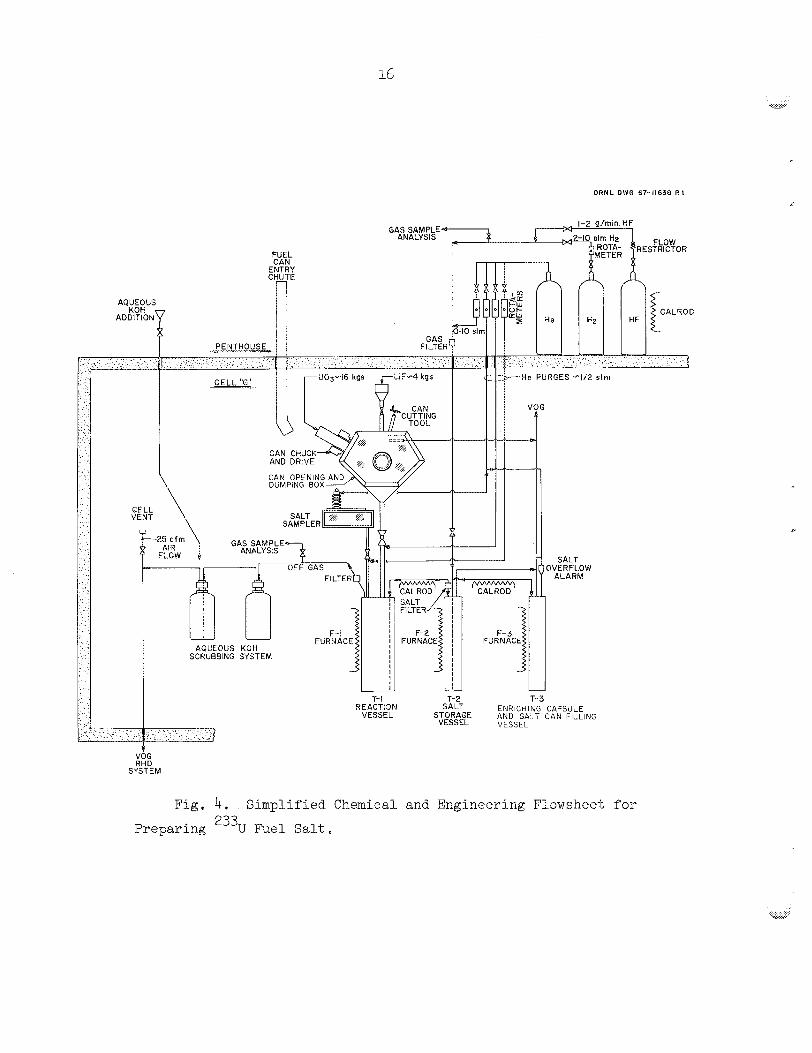
4.3 Process Equipen-t
The e q u i p e n t flcwsheet shown i n P ig . 4 i s a s impl i f ied presentat ion
of t h e m L j o r corfipanents req-aired i n t h e proceEs These components are:
( I ) t he f u e l decanning s t a t ion ,
(2) t he r eac t ion o r oxide treatment vessel ,
(3) the sal t storage and t r a n s f e r vessel ,
(4)
(5) t h e off-gas scrubbers
various containers for shippicg the product,
I n addition, t h e process requi res many o ther smaller pieces of
eqdipment, such as : t he oxide can preparat ion equipment, t h e in-cell t i t r a t i o n assembly, t he furnaces f o r t he vessels , t h e enrichment capsule
d r i l l i n g and weighing s t a t ion , dlsconnect s t a t i o n s f o r e l e c t r i c a l and
instrument l i n e s and process gas bines, and work t ab l e s and too% racks.
Figures 5 and 6 show some of' t h i s equipKent a f t e r i n s t a l l a t i o n .
A l l se rv ices and reagent scurces are located i r a t h e penthwse
outs ide the c e l l .
.. .
ORNL D W G 67-11638 R 1
GAS SAMPLE ANALYSIS FLOW
RESTRICTOR
---He PURGES -1/2 slm 1
~ i g . 4. Simplified ChernizaI acd Engineering o ow sheet far
Preparing 233Y Fuel Salt.

.. . v..... . . . .._ vw
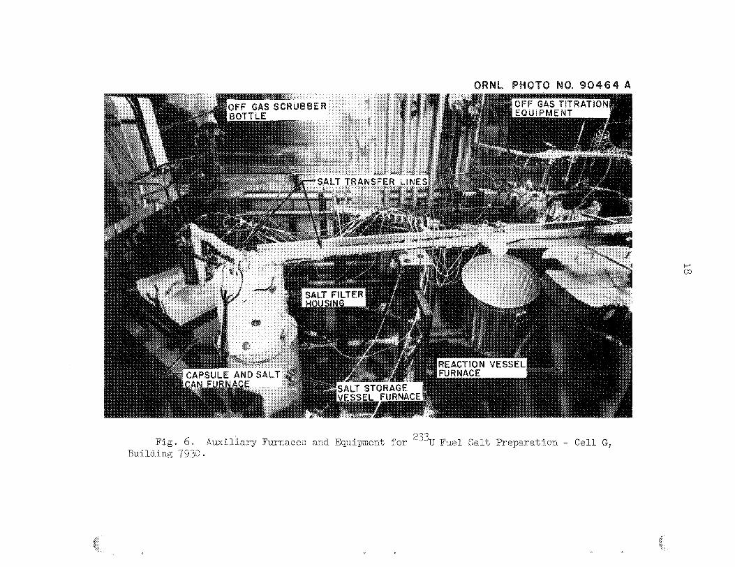
Fig . 5. Yiin Reaction Vessel Furnace and Auxiliary Equipment fcr 233U Fuel S a l t Preparation - Cell G, Building 793Q.
18
c 0
k
0
b
.. ...
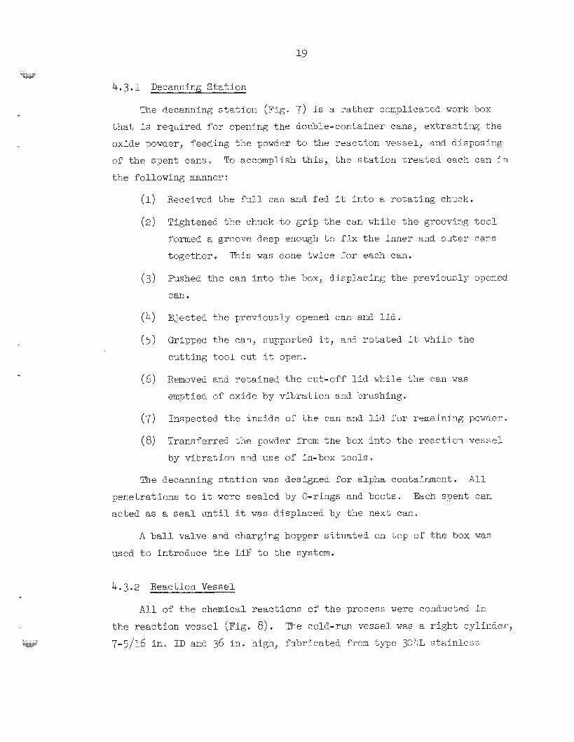
4.3 e I Becanxirig S t a t i o n
The decanni3g s t a t i o n (Fig. 7) i s a r a t h e r complicate, 3 work box
t h a t i s reqLired ?or cpening the double-container cans, ex t r ac t ing the
oxide powder, feeding t h e powccr to t h e react tor , vessel: and d i s p x i n g
or t h e spen5 cans. To accc)mplish t h i s , t h e s t a t i o n t r e a t e d each can i n
t h e following manger :
Received t h e f u l l can and f ed it i n t o a r o t a t i n g chuck.
Tightened t h e ch-xk co grip t h e can while t h e grocvlng t o o l
fomed a groove deep eno~@ t o f j x t h e Inner end ou te r cans
together . Tkis was done twice ?or each can.
Pushed t h e can i n t o t h e OX, displacing t h e prevlously opmed
car1 a
Ejected ;he previcusly opened can and l i d .
GrLpped t h e can, supported it, anC r o t a t e d it ~ h i l e t h e
c x t t i n g tocl cut it oper,.
Removed and r e t a ined t h e cv.6,-off Ild while t h e can w a s
emptied of oxide by v ib ra t ion and kru.shing*
Inspected t h e in s ide of' t h e can and l i d f o r r m a i n i n g pcwder.
Transferred t h e powder Y r c m the box i n t o t h e r eac t ion v e s s e l
by v ib ra t ion and use of in-box t o o l s .
Pie decannixg s t a t i o n w a s designed f o r alpha containment. A I 1
pene t r a t ions t o it were sea l ed by O-rings and boots. Each spent can
acted as a. seal u n t i l it w a s d isplaced by t h e next can.
A ball valve and charging hopper s i t u a t e d on top of t h e box was
used t o Introduce t h e LiF t o the system.
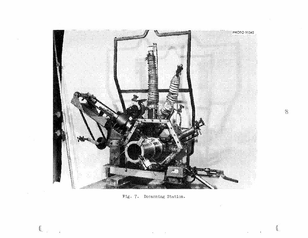
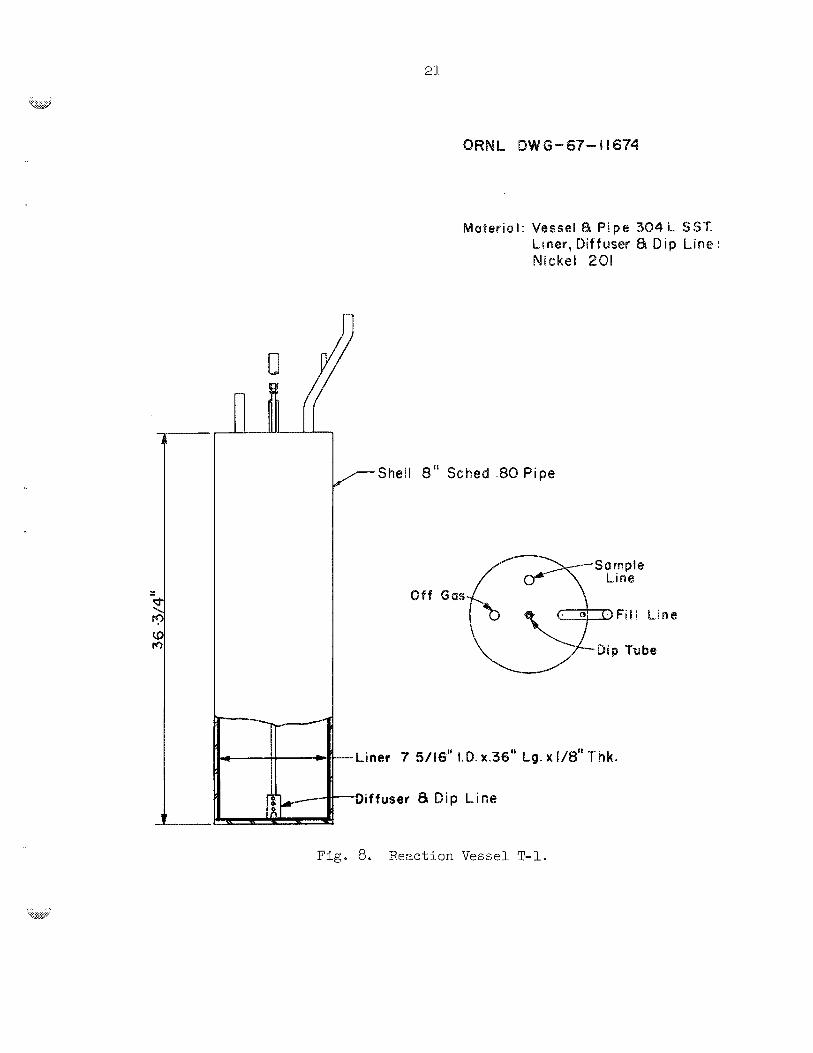
4.3.2 Reaction Vessel
A l l of t h e chemical r eac t ions of t h e process were conductet; i n
t h e r eac t ion vessel (Fig. 8). 7-7/16 i n . ID and 36 i n . high, f ab r i ca t ed from t y p e 301;L s5alnless
The cold-run vessel was a r i g h t cylinder,
20
21
ORNb DW e-67- I I674
Material: Vessel 8 P i p e 304L SST. Liner, Diffuser 8 Dip Line: Nickel 208
w
Sample Line
O f f Gas
Fig. 8. Weactisn Vessel T-P.
22
s t e e l ; it ccntaineci a free-stanciing l i n e r , 1 / E i n . th ick, constructxd
from type 201 nickel , and w a s designed, on t h e bas i s of stress rupture
data, f o r R epecif ied serv ice 1Lfe. The vesse l conteined nozzles t o
permit powder addft isn, sa l t sampling, g a s e o ~ s e f f lxen t discharge, and
product t r a n s f e r . Wpon completion of t h e cold rmJ the design of t he
vesse l was modified t o include a t runcated ccn ica l boxtom t o provlde
b e t t e r contact of' t h e reagent gases . The Frodact isn runs were conducted
i n t h i s vesse l .
vessels i E l i s t e d i n Table 1.
Design information f o r t h i s ves se l and t h e o ther process
4.3.3 S a l t Storage an6 Transfer Vessel
The t r a n s f e r vesse l (Fig. 9) w ~ s a r igl i t cyl inder , 4 i n . ir, diameter
and 36-1/2 i n . t a l l , construstee sf type 231 nickel.
nozTles, one cf which w a s a spare . %e funct ion of t h i s vessel wzs t o
receive a f i l t e r e d , pcrif ' ied ba teh of t he enriching caEt f r o m t he re-
ac t ion w s s e l and t o dispense It t o the various product shipping eon-
ta iners . It w a E necessury for t h i s vesse l t o s t o r e salt f o r 24 hr o r
more Cwlng the ehapgeou'e of some of t h e shipping conteiners .
~t contained f i v e
The shipping containers were arranged i n t o th ree a r rays f o r khe
f i l l i n g operations. Eater, upon completion of t h e f i l l i n g operat ion
a.nd freezsing cf t h e salt, each a r r ay was disassembled i n t o ir-dividuel
ccn ta iners f o r shipmen5 t o t h e bER3.
~ 1 2 e f i rs t a r r a y ( ~ i g ~ 10) consis ted of 4-5 enrictmext capsules
(see Fig. E % ) , each of which was 3/4 i n . i n d iane ter and 6 i n . long
and designed t o coctain 96 g OS crmiun.
i n series and arranged i n three 15-capsule decks.
containing P iqLid l e v e l de tec t ion elements and themocsuples was the
last vesse l i n t h e s e r i e s . The tubing connections in to , and out of',
ezch capsule were prec i se ly posi t ioned SO that u n i f o m f i l l i n g ani?
sulclsequent blowback sf the o v e r f i l l were possible . Two holes were
d r i l l e d i n each capsule t o permit t h e sa l t t o flow out when t h e capsule
me capsules were connected
An overflow pot

23
Table 1. Equipment Design Information: MSRE 233U Fuel Salt Preparation
Reaction Reaction Salt Furnace Furnace Furnace Vessel Vessel Salt Storage Addition Enrichment Liner Liner Liner
Item or Requirement T-1 Outer Inner Liner Vessel T-2 Cana F- 1 F- 2 F- 3 Capsule
201 Ni
900
201 Ni
700
20
15
- 20
2560 psi at 20# gage
3000 psi at 700" Cb
36- 112
1 /4
114
4- 112
15./64
4- 1/32
- -
- -
304L SS
600
20
15
- -
-
-
Variable
5/16 - 112
114
2- 112
0.065
2-37
- -
- -
300 ss 300 ss 304 SS ELC
goo+ goo+
Open Open
Type of material
Maximum operating temp., OC
Maximum operating pressure, PS it3
304L SS
900
%j+ at 9000~~ 20# at 700°C
goo+
Open Free standing liner in reaction vessel; no pres- sure difference developed
Maximum operating vacuum, Psi@;
Design temperature, OC
Design pressure, psig
15
900
6# at 900"~ (Limiting condition)
Calculated maximum stress, Psig
727 psi at 6 Psig
Maximum stress is that due to head of salt in liner and is negligible
No load carried No load carried by bottom plate by bottom plate or wall or wall
glO psi at 930°C
Allowable maximum stress at maximum operating temp.
35-718
118
Overall height, in.
Bottom plate thickness, in.
37
114 (reinforced with welded beam on diam)
- 10- 314
0.359
10.032
16
318
Flat head thickness, in.
Outer diameter, in.
Wall thickness, in.
Inner diameter, in.
Top flange OD, in.
Top flange thickness, in.
Hemispherical bottom wall thickness, in.
Hemispherical top, in.
- I
Designed by MSRE. a
blO,OOO hr creep-rupture data; design based on service << 10,000 hr.

2 m
Y
n,
Y
I C !E rD u)
u) .. P 0
I z ..
0
;D
- .. sp C
'0
rD v) u) ..
z r
25
6” PHOTO 91466
Pig . EO. F i l l i n g Array Consisting cf ’$5 Capsul es.
26
ORNL DWG- 67-1 8676 R i
Fig . 11. Typical Enrichment Capsule.
i s lowered i n t o t h e MSRE pump bowl. A cable-and-latch assembly w a s
a t tached t o each capsule for use i n t h e sampler-enriched operation at
t he r eac to r .
The second a r r a y ( ~ i g . 12) c o n s i s t e j of four 2-i/'2-~n.-diam -3y
34-in.-long cans connected i n series f o r f i l l i n g operat ions.
designed t o contain 7 kg OS uranium and had an instrumentee overPlow
pot . The cans were l a t e r Ciisassembled, and t h e top arid bottom plugs
were removed; then the cans were f i t t e d wLth l i f t i n g b a i l s and bottcm
"stopper-tee" plugs and welghed.
t i m e , t o t h e ISRE, where the bottoE plug of' each can i s rexoved bef'ore
t h e c m i s lowered i n t o t h e d ra in tank. In t h i s tank, t h e sa l t xelts
and runs out of t he container .
Each w a s
They are being shipped, one a t a
'fie t h i r d a r r a y (Fig. 13) contained a group of s i x 2-l/2-inB-diaK
variaS%e-length ca r s (see Fig. 14) t h a t were s i m i l a r i n desrign end
arracgement t o those i n t h e second ar ray . One of these cans w a s used
t o s t o r e excess product rnaterial t h a t was blown back from the o ther
f i v e cans a f te r they had been f i l l e d t o overflow. The la t te r cans were
designed t o contain 0.5 t o 3 kg of urar im (2 cans, 0.5 kg ekch; one
can, 1 kg; one can, 2 kg; and one can, 3 kg).
4.3.5 Scrubbers
A caus t i c scrubber system w a s Lnstalled t o neu t r a l i ze the MF e f f luen t from t h e r eac t ion vesse l before it w e s discharged to the T U i
KOG system. The scrubbers, namely, four l3 -ga l polyethylene b o t t l e s
f i l l e d with 10% KOH, were connected i n series and f i t t e d with t h e
necessary f i l l - and-d ra in connections. The f i r s t b o t t l e i n t h e series
w a s kept empty, and the d i p l i n e s i n t h e subsequent b o t t l e s were posi-
t ioned a t an exact depth.
t o r e t a i n any l i q u i d t h a t might Slow back toward t h e r eac t ion vesse l
( i n the event t h a t the pressure d i s t r i b u t i o n i n t h e system became
reversed) .
rence of a vacuum, which could cause col lapse of t h e b o t t l e s .
Thus t h e f i r s t b o t t l e had an adequate volume
Also, a vacuum breaker w a s i n s t a l l e d t o prevent t h e occur-
28
PHOTO
:*
984M
Fig . 12. Second F i l l i n g Array: Four Cans, Each Containing 7 kg of UranirJm.
Fig . 13. Tkird Filling Array Containing Six Shipping Conteiners of' Miscellaneous S izes .
30
w G - 67- I I 67 7
Selt eapaci t y
DIMENSION 'A' Kg 3 3.5 9 2 I' 9.0 14.802 3.0 IO.102 2.0 5.402 I .o 3.05% 0 . 5
2 . I x 0.865" \Ala I I Tlebi ng
Fig. 14. Salt Adbition Can.
Raschig r ings had been i n s t a l l e d t o prevent col lapse of t h e
b o t t l e s i n t h e scrubber system used i n the cold run; however, these
r ings preverted u n i f o m mixing and were subsequently replaced by R
vzcu~.m breaker
4.3 e 6 Miscellaneous Equipment
Oxide Can Lengthening Equipment. - The 233U0 decanning s t a t i o n
w a s designed by using can drawings and eample cans from t h e Savannah
River Laboratory. After t he decanner w a s fabr icated, it w a s discovered
t h a t the a c t u a l cans were 1-3/4 i n . sho r t e r than denoted on the drawings
(The measurements o f t h e a c t u a l cans had not been checked c lose ly be-
cause of t'ne high r ad ia t ion l eve l s of t h e oxide.) Since modification
of t h e decanner was impractical , w e decided t o lengthen each can 1-1/2
i n . by cementing an extensicjn on it. Three i t e m of ecpiprr,ent, as
shown i n F ig . 15, were required t o accomplish Lhis:
f i x t u r e t o bevel t h e end of t h e can, (2) a press t o force t h e extensizn
onto t h e can, and ( 3 ) a f i x t u r e t o cure the epoxy r e s i n used i E t h e
cernented j o i n t a
3
(1) a nachining
In-Cel l T i t r a t i o n Assembly. - The off-gas t d t r a t i o n assembly
consis ted of a t r a i n of t'nree +in.-diam by 6 - i n . - t a l l @.ass vessels ,
a w e t t e s t meter f o r measuring gas flows, alnd t h e necessary tubing and
valves t o permit reagents t o be added azd flushed f r o m outs ide t h e c e l l .
Fwnaces and Heaters. - Three high-temperat;e> e l e c t r i c a l -
r e sh tance -hea ted furnaces were i n s t a l l e d i n c e l l G f o r temperature
con t ro l of vesse ls used i n t h e treatment, storage, and transfer of t h e
sa l t
8 7-1/2-kw, 4-7/8-in.-cavity u n i t w a s used for t h e t r a n s f e r vesse l ;
anu a 10-kw, 4-7/8-in.-cavity u n i t was used f o r t h e shipping contelner
assemblies. Locally f ab r i ca t ed clamshell hea te rs using tubular
res is tance-heat ing elements provided hea t to t he nozzles Located on
t h e tops of t h e vessels.
taching tubular hea t ing elements t o t h e tu3ing and then appbjTing thermal.
i n su la t ion . me off-gas l i n e (and f i l t e r ) w a s heated with e l e c t r i c a l ,
res is tance-heat ing tape t o prevent condensation of €IF o r water v ~ p o r
i n t h e l i n e .
A Zk-kw, 12-in.-cavi ty furnace w a s used for t h e r e : x t i o n vesse l ;
The sal t t r a n s f e r l i n e s were heated by at-
33
Enrichrcent Capsule Dr i l l i ng and Weighing Fix ture . - Two holes were
d r i l l e d i n each of' 45 enrichrent capsules t o pemHt the salt 'vo f'lcw
out whex t h e capsule i s immersed i n the sal t i n t h e r eac to r pump bcwb.
Upon disassembly of t h e capsule f i l l i n g arr%yJ each capsule w a s inser2eCL
i n t o t h e work box (Pig. 16); here, a bottom o u t l e t hole and a top vect
hole were d r i l l e d 4n t h e capsule, the capsule was weighed, t h e l i r t i n g
b a i l wes t e s t e d for i n t eg r i ty , and the capsule was Inser ted i n t c the
shipping carro-Jsel e The t ransparent box served as conta iment during
the d r i l l i n g operat ion. Off-gas from t he capsule d r i l l i n g box passed
through an absolute f i l t e r and W%E then discharged t o the p lan t ves se l
off-gas system.
Disconnects. - The e l e c t r i c a l and thermocouple disconnects used
i n t h e cell were standard commercial u n i t s . Generally, one-half of t he
disconnect w a s rrounted r i g i d l y t o f a c i l i t a t e making and breaking opera-
t i ons with the master-slave maariprulators *
Several types of pipe ard tubing disconnects were uced. I n general,
t he gas se rv i ce line: u t i l i z e d ball-check quick disconnects. Compressior
f i t t i n g s were used i n t h e salt t r a n s f e r line:: and i n the main off-gas
l i n e s . Conventional screwed pipe connections were used i n arets where
remote operat ion of t h e j o i n t was not consldered necessary. Loca1l.y
dceigned and fabr ica ted connections w e r e used i n s eve ra l large-diameter
j o i n t s t h a t would possibly r equ i r e remote rmintenance.
Work Tables and Tool Racks. - The prccess equipment w a s pcsitioned
i n t h e ceLl t o ob ta in maximum advantage of t h e c a p a b i l i t i e s of t h e et@+,
ava i l ab le master-slave maxipubators. Extensive use was made of support-
ing s tands and mounting framework. Tool racks for t h e required hand
too l s were located a t t he major work cen te r s .
spaces between t h e process equipment and t h e c e l l w a l l s were f i l l e d with
t r ays t o provide ex t r a work areas, space f o r temporary t o o l storage, and
a sur face on which t o catch too l s and s m a l l equipment L t e m s t h a t were
dropped. A l a rge work t a b l e (Pig. 14) w a s i n s t a l l e d t o accommodate the
product shipping container disassembly, t he shipment preparat ion opera-
t i ons , and t h e capsule d r i l l i n g and weighing f i x t u r e .
Where possible , t h e void
m a 43 6)
Fig. 17. In-Cel l Work 'Fable .
The tab les , racks, and supports were fabr ica ted from carbon s t e e l ;
t he t r ays were fabr ica ted from s t a i n l e s s s t e e l .
4 .4 Operating Procedures
Operating procedures were developed f o r each of t h e 25 separa te
(These procedures were
Brevi ty and conciseness were
operations required f o r the f u e l production.
wr i t ten before the cold rilll w a s nade. )
s t ressed .
of t he experience gained i n the col6 rw. Review and revis ion, on a
day-to-day basis, continued throughout t he 233U production runs ; the
minor equipment f a i l u r e s and malfunctions t h a t occurred durring these
runs led t o extensive procedural changes t o ensure continued production
of a high-qual i ty f u e l concentrate.
Complete rev is ion of' most of them was necessary as a r e s u l t
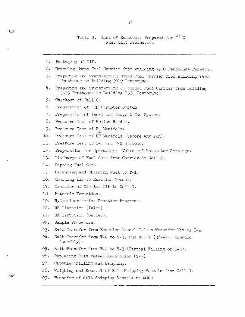
Tables 2 l i s t s the runsheets thak were prepared -
'The run with depleted uranium provided f u l l - s c a l e t e s t i n g OP t he
chemical process, operat ional procedures, and sf most of t h e equipment
i n the absence of a penetrat ing r a d i a t i o n f i e l d . I n t h i s run, 14.6 kg of cranium oxide (11.6 kg of '35U) plus 3.4 kg of LiP were charged t o
the system t o produce 18.7 kg of LiF*W4 (73-27 mole '$) eu tec t i c . 5
5 1 Preoperatisna.1 A c t i v i t i e s
The period from September 15, 1967, through January 159 1968, w a s
devoted t o f a c i l i t y t e s t i n g ; process equipment fabr ica t ion , i n s t a l l a t i o n ,
and testing; operator t r a in ing ; preparation of procedures and manuals;
and preparat ion of t h e process s a f e t y review, the c r i t i c a l i t y review,
and the radiochemical p lan t s a f e t y ana lys i s .
5.2 Mechanical Operations
The rm with depleted uranium began January 15, 1968, with the
loading of 2 3 8 ~ ~ filled cans i n t o c e l l G from the shielded c a r r i e r . 3-
.. .
T & l e 2* L i s t of Rimsheets PrepareE f o r 233, Fuel S a l t Prcduction
Pa-ckaging of Lip.
Renoving Empty Fuel Ca.rrier Prom Building 793C Penthouse Pedes5al
Preparing and Tra.nsferring &pty Fuel Carrier from Building 7930
Preparing and Transferring of Loaded Fuel Car r ie r from Building
Checkoilt of Cell G.
Preparat ion of KOH Scrubber System.
Preparat ion of I n e r t 2nd Reagent G a s System.
Pressme T e s t of H e l i u m Header.
Pressure T e s t o f Iz, L%nifold.
Pressure Test of EF Ihn i fo ld (before any run).
Pressure T e s t of T - 1 an6 T-2 Systems.
beparatior?_ for Operattion:
Discharge OY Fuel Cans f r o m Carrier t o Cell G.
Capping Fuel Cans.
Decanning and Charging Fuel to T-1.
Charging EiP t o Reacticn Vessel.
Tyansfer of Odd-Lot LiF t o Cel l G.
Eut e c t i c Format ion
HydroYluorination Reaction Progress.
HF T i t r a t i o n ( I n l e t ) .
EF T i t r a t i o n (Oat le t ) .
Sample Procedure.
Sa l t Transfer f r o m Reaction Vessel T-E t o Transfer Vessel T-2.
salt Transfer from T-2 t o T-3, Run NO. P (3/4-in. Capsule
S a l t Transfer from T-2 t o T-3 ( P a r t i a l F i l l i n g of T - 3 ) . Replacing S a l t Vessel Assemblies (T-3 ) . Capsule Dr i l l i ng and Weighing.
Weighing and Removal of S a l t Shipping Vessels from Cell G .
Transfer of S a l t Shipping Vessels t o TERE.
Penthouse t o Euibding 3C19 Penthouse.
3019 Penthouse t o Building 4930 Penthouse.
2
Valve m d Ro tme te r Se t t i ngs .
Assembly) e
The UO had been processed a t t h e Y-12 Plant, and t h e empty inner and
outer cans had been obtained from the Savannah River Laboratcry. The
cans had been f i l l e d with the oxide and sealed by a magnetic f o m i n g
technique t o simulate the product cans t h a t would later be used i n t h e
prodaction runs. The can opening box d id not perform s a t i s f a c t o r i l y ;
therefore , it w a s removed f'rom the c e l l and extensively modified. The
alignment tolerarices were relaxed, components were strengthened, addi-
t i o n a l equipment w a s i n s t a l l e d to a i d i n t r ans fe r r ing the powder from
t h e box, ~ n d t h e viewing c a p a b i l i t i e s were increased.
3
D i f f i c - d t y w a s encountered in t r ans fe r r ing t h e LiF from t h e de-
The ava i l ab le v ib ra t ion w a s in- canning box to t he r eac t ion vesse l .
adequate, and no provis ion had been made t o sweep or "rod1' t h e powder
out and down through the powder addi t ion l i n e .
located on t h e equipment i n slwh a way t h a t most of' t h e i r force was
imparted t o t h e f i x t u r e s and mechanism i n t h e box. This r e su l t ed i n
sone damage t o t h e equlpmect.
spar ingly and with cc.,ution.
The v ib ra to r s had been
Because of t h i s , t he v ib ra to r s were used
5.3 Chemical Operations
Chemical operat ions began on January 24, 1968, with t h e s i n t e r i n g
operation, which w a s cofiducted a t 9 0 ° C with a helixm flow of 1 s t d
l i t e r / m i c through t h e bed. The s i n t e r i n g treatment w a s i m e d i a t e l y
f'cliowed by t h e hydrogen reduct ion s-cep z t t he s a m e temperature. A
2-1iter/min i ' i o w of gas, cons is t ing i n i t i a l l y of 0.1 l i t e r o f hydrogen
and 1.9 Liters of hel iux per minute, Wac a t t a ined i n i t i a l l y . D-e com-
pcs i t i on of t h i s gas w a s adzusted pe r iod ica l ly u n t i l a flow of pure
hydrogen w a s obtained. Then the flow rate w a s increased, i n increments,
t o 10 l i t e rs /min , where it was maintained f o r 5 h r .
ment, ;he sintered-met21 off-gas f i l t e r became plugged. Subsequent
examinatiosl of t he f i l t e r u n i t revealed t h e presence of' a hard f i l t e r
cake. Water vapor, which is evolved during t h e reduct ion process,
cczld h a w ccndensed on t h e f i l c e r i n t h e event t h a t t h e f i l t e r hea te r
w a s improperly operated; t h i s would have permitted t h e f i l t e r temperature
t o drop below t h e dew poin t of' t h e e f f luen t .
During t h i s treat-
k J

'-
The cc?nversicn of' t h e oxide t o t he f luo r ide began January 27, 1968. Anhydrous hydrogen f luo r ide mixed with hydrogen ( 3 2 rneq of ID' per l i t e r
of hydrogen) wzs i n j ec t ed through a d i p l i n e t o t h e botcom cf t h e UO, bed a t t h e ra te of 2.2 Eiters/nGn. This r eac t ion began a t WC;"C, and
t h e temperature was pe r iod ica l ly decreased t o maintain the m e l t a t
about 50°C above t h e l iqu idus temperatme.
r a t u s w a s used t o monitor t h e El' i n t he e f f luent , but t h e r e s u l t s were
inconclusive; thus another t i t r a t i o n un i t t h a t permitted prec ise addi-
t i o n of t h e equ i l ib ra t ing reagents from outs ide the ce1.l w a s Ciesigned
and i n s t a l l e d . The da ta obtained with the new equipment showed t h a t
the u t i l i z a t i o n ot' HF w&s e s s e c t i a l l y zero (which indiceted t h a t t h e
conversion o f t he oxide w a s complete) af ter 295 h r of hydrofluorinat ion.
An attempt to sample t h e m e l t was unsuccessful because of the presence
cf' a hard top layer (o r c r u s t ) F h noise vas evident from a l i s t e n i n g
rod i n s t a l l e d t o de t ec t bubbling from the d i p l i n e . It was concluded
t h a t t h e olip l i n e had broken, by corrosi.cn o r ne l t ing , above t h e l i q u i d
in t e r f ace . This vmld account for t he lack o f HF u t i l i z a t i o n and t h e
slow progress i n tke conversion of t h e oxide. Subsequent examination of
t h e d i p t T h e showed a l a rge hole approximately at t h e Inkerface. A new
d i p tube, along with a s e n s i t i v e sound detector , w a s i n s t a l l e d , and the
IT3 treatment w a s resumed. Bubbling i n the melt was e a s i l y detected;
and, f o r the first; time, rea,sonEble valu.es f o r t h e KF u t i l i z a t i o n were
obtalned. A f t e r 250 hr of add i t iona l KF treatment, t h e d i p l i n e be-
erne plugged at a loca t ion about 1-3/4 i n . Yrom i t s open end.
examinatioc, t h e plug material appeared t o be uranium oxide.
sequent lLnes plugged approximately a t t h e gas- l iqu id in t e r f ace within
t h e tube; i n these instances, t h e plug material also appeared t o be
uranium oxide. It was obvious, then, t h a t excessive mois t -ne w a s belr-g
introduced i n t o t h e m e l t by t h e gases used i n t h e process.
w a s solved by i n s t a l l i n g R colurnn f i l l e d with magnesixn perchlora te i n
t h e helium system End by i n s t a l l i n g a c a t a l y t i c recombiner, a molecular-
s ieve drying c o l m (with regenerat ive e a p c b i l i t i e s ) , and a moisture
analyzer i n the helium system.
r'
'Be i n - c e l l t i t r a t i o n appa-
Upon
Four su5-
"'his prsblea
The ef f luent gases from the reac t ion vesse l were d i rec ted t o a
caus t ic scrubbing system, which conslsted sf pclyethylene b o t t l e s f i l l e d
with 2Q$ KQH so lu t ion and RaschLg r ings ( t o prevent co l lapse) .
ea r ly s tage i n the process, t h e d ip l i n e s i n the scrubber b o t t l e s
plugged, and a white p r e c i p i t a t e appeared. Frequent sparging t o promote
mixing, frequent recharging of the caus t ic solut ion, r i n s ing with hot
water, and a decrease (from 2076 t o lC$) i n KOH concentration permitted
use of t he system f o r the r e m i n d e r of t he cold run. It was f e l t t h a t
t he Raschig r ings were a major contr ibutor t o t h i s problem i n t h a t they
promoted s t r a t i f i c a t i o n of t he solut ion; t h i s w a s confirmed by the
colored in t e r f ace t h a t appeared i n t h e b o t t l e s when phenolphthalein
ind ica tor w a s present . At the conclusion of t h e cold rung the scrubber
system was completely replaced by one t h a t contarlned spare l i n e s and a
vacum breaker ( t o prevent possible b o t t l e col lapse)
renote replaeernent and f lushing of a l l l i n e s .
A t an
and permitted
Although it gave s a t i s f a e t o r y r e s u l t s i n the smell-scale development
runs, t h e technique of measuring the Eiquidus temperature of the n e l t
and subsequently determining, from the binary UF4-LiF phase diagran,
t he progress of' t he conversion reac t ion d id not prove successful i n
t h i s system. The lieat capac i t ies and thermal i n s u l a t i o n of t he system,
along with poorly located thermocouples, obscured t h e i n f l e c t i o n i n the
temperat-are decay curve of t h e melt upon cooldown.
u t i l i z a t i o n data, along with rnaterial balences for t he system, provided
s u f f i c i e n t reac t ion progress information. When the r e a c t i o n was judged
t o be complete, .m m f i l t e r e d sample of t'ne m e l t w a s withdrawn and ena-
Ijrzed, chemically and petrographically, f o r oxide content.
However, t h e KF
The p u r i f i c a t i o n cf t he melt, by the reduction of t he m e t a l f luo-
r ides t o metal, w a s conducted without inc ident .
t he e f f luen t gas proved t o be n r e l i a b l e means of determining t h e end
point of t h i s reac t ion .
t he conclusion of t h e p u r i f i c a t i o n s t ep .
considered t o be representa t ive o f the packaged product s ince t h e melt
was f i l t e r e d i n t h e t r a n s f e r operation. The cold rru? product analyzed
as follows:
T i t r a t i o n of t h e E? i n
F i l t e r e d and ;znf i l tered samples were taken a t
The f i l t e r e d samples were
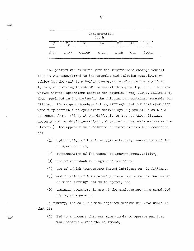
41
Concentration
U Ki Fe Cr Al S (Wt $)
61.0 0.02 0.C065 C.007 c.26 0.1 9.002
The product was filtered into the intermediate storage vessel;
then it was transferred t o the capsules and shipping containers by
subjecting the salt to e h e l i u ~ overpressure of approximately l2 to
lg psig and forcing it out of the vessel through z dip line.
volved several operations because the capsules were, fiyst, Filled and-,
then, replaced in the system by the sh-ipping can container assembly for
"kits in-
c-. , d I i n g . The compression-type tubing fittings used for this operation
were very difficult to open after thermal cycling and after salt had-
contacted then.
properly and to obtain leak-kight joints, using the master-slave manlp- ulators.)
of:
(Also, it was difficudt to make up these fittings
'The approach to a so lu t ion of these difficulties consicted
(1) modificaticn of the intermedizte transfer vessel by addition
of spare nozzles,
(2)
( 3 )
yeorientation of the vessel to ixprove accessibility,
use of redundant fittings when necessary,
(4) use of a high-temperature thread lubricant on a l l fittings,
(5) modification of the operating procedure to reauce the nxmker
of times fittings had to be opened, and
training operators in use of the manipulators on a simzlated
piping arrangement. (6)
In smary, the cold run with depleted uranium was invaluable in that it:
(I) led to a process that was more simple to operate and that was corripatible with the equipment,

42 . ... -*-
(2) pointed out design and fabrication deficiencies in the
equipment , provided on-the-job training for the operators and supporting
personnel, ( 3 )
(4) tested the operational procedures, showing the need of exten- sive changes in them, anti
(5) showed that comprehensive remote maintenance procedures woxld
probably be mandatory to ensure successful completion of the
2 3 3 ~ fuel concentrate production runs
Three production batches, using the low-temperature flowsheet,
were required in order to prepare 63.4 kg of the fuel-enriching concen-
tTate, 7LiF-233UF,tm This concentrate contained 39 kg of uranim (35.6 4 ~
kg of 233U)m completed July 30, 1968. The kg enrichment capsules were filled with a portion 0% the first-run product; the four 7-kg shipping containers
were filled with the remainder of the first-run product, all cf' the
second-run product, and a portion of' the third-run product; the mis- cellaneous shipping container assembly was filled with the remainder
of the third-run product.
enrichment capsules were delivered to the Molten Salt Reactor as required
in the reactor enrichment schedule.
The first run began May 9, 1968, and the third run was
The ten salt shipping containers and the 45
6.1 Peed Materials
The 233U0 had been prepared in batches by using 7 M NH: OH (in 3 - 4 excess) to precipitate hyCrcus uraniam oxide from solutions that con- tained 10 to k j g of uranium per liter and were 1 M in HNO and NH NO 3 4 3' - The uraniuni in the feed solution had been purified and isolated in 1964 and 1965 by solvent extraction fo%lswed by ion exchange.
ments decreased the concentrations of plutonium, thorium, fission prod-
ucts, and corrosion products (iron, nickel, and chromium) to acceptably
bow levels. Table 3 shows typical analyses of the oxide feed material.
These treat-
v
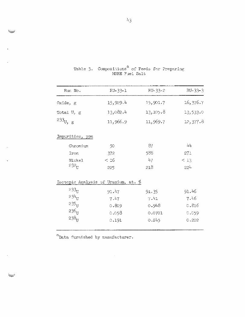
a Ta,ble 3. Compositions cf Feeds f o r Preparing IGRE Fuel Salt
R u n No. RU- 33- 1 RU- 33- 2 RU- 33- 3
Impurities, ppn
I so top lc Analysis of Uraraium, at. Lifo
91 4 47 910 35 233,
P3lCU 7.47 7.4: 235, 0.809 0.948 236, 9.058 o .e701 238u 0 .Egl 0 -245
gn 0 46 7.46 0 * 816 0.059
0 -232
a Data furnished by manufac t w e r .
.. . , ... . ~~ .. v.:.,,
44
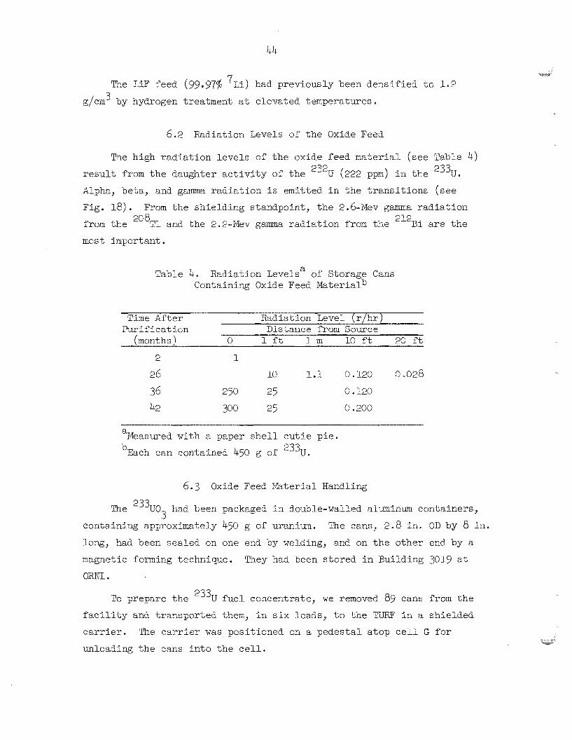
The LiF feed (99.97$ had previously been densified to 1.2 3 g/cm by hydrogen treatment at elevzted temperatures
6.2 Radiation Levels of the Oxide Feed
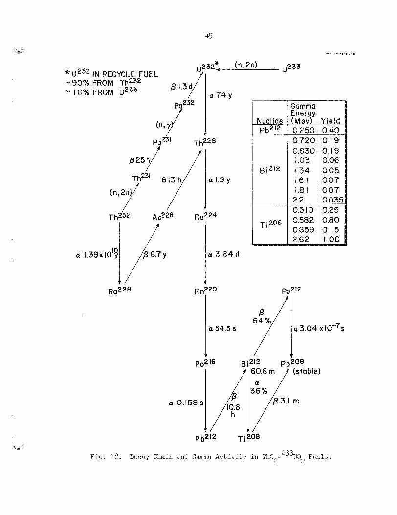
The high radiation levels of the oxide feed material ( s e e Tabhe 4) result from the daughter activity of the 232U (222 ppna) in the 233ue Alpha, beta, and gama rac?iation is emitted in the transitions (see
Fig. 18) e From the shielding standpoint, the 2 . 6 - ~ e ~ gama radiation
fron the 2G8Tl and the 2.2-Mev gama radiation from the 212Ei are the most important.
Table 4. Radiation Levels" of Storags Cans Containing Oxide Feed MaterialD
Purificaticn Distance f r o m Source (months) 0 1 ft 1 m a0 ft 20 ft
a
26 10 1.1 13.120 0.028
36 250 25 0 D 120
42 300 25 0.200 ~~
a Measured with a paper shell cutie pie . 'Each can contained 4-50 g of 233,
6.3 Oxide Feed ?.laterial Handling
'Fhe 233U0 had been packaged In double-walled alminum containers, 3 containing approximately 4-50 g s f uranium. The cans, 2.8 in. OD by 8 in. lowj had been sealed on one end by welding, and on the other end by a magnetic f o m i n g technique.
QRNl
They had been stored in Building 3019 at
TO prepare the 2 ' ~ ~ fue l concatrate, we removed 89 cans from the factlity and transported them, in s i x loads, to the TURF in a shielded
carrier. The carrier was positicned on a pedestal atop cell G for
unloading the cans i n t o the cell.
Nuclide p p 2 -
n
Fig;. be. Decay Chain and Gamma Ac t iv i ty in 3 0 -"33U9 Fue ls . 2 2

46
-- NQ spread of contamination or excessive r a d i a t i o n exposure t o
personnel occurred during the removal of t he oxide cans from t h e s torage
f a c i l i t y , during t h e i r t r a n s f e r t o TURF, or during t h e i r discharge from
the c a r r i e r to c e l l G .
I n c e l l G, t h e cans were gaged, and any b u r s or excess w e l d metal
were removed by f i l i n g . Three separate operations were required t o
elongate the cans t o the 9-L/2-ine length required f o r proper operat ion
of t h e can opening box.
" t rue" them.
inser ted i n t o the c e l l through the s m a l l - i t e m s e n t r y po r t . This cap
w a s i n s t a l l e d on the can i n a pressing f ix tu re , and then t h e can (with
cap) w a s placed i n a curing f ix tu re , where f i v e cans a t a time were
c-xed m d e r longi tudina l pressure for 1 h r a t a temperatxre of 110 t o
120°C. m e can preparat ion equipment functioned s a t i s f a c t o r i l y , except
on one occasion i n which the dr ive motor on the can machining f i x t u r e
burned out . The remaining cans for t h a t run were dressed with a f i l e ,
and the caps were i n s t a l l e d without inc ident . Later, a new motor was
i n s t a l l e d remotely i n the f i x t u r e .
F i r s t , t he cans were machined on one end tc
A premachined end cap (with epoxy cement appl ied) was
The elongated cans of oxide were opened, one at a time, i n t h e
decanning s t a t i m . This w a s a time-consuming operation involving tke
zlse of equipment t k a t had been reccgnized daring t h e cold run t o be
mzrginal.
t a ted the cans while a cu t t i ng wheel opened them ins ide an alpha-sealed
box.
and i n some instances, a c t u a l l y hindered the operat ion.
The decanner had a rugged chuck assembly t h a t held and 1-0-
Most of t he other attachments i n the box were of l i t t l e velue,
The major problem i n the decanning operation can be sumarized
as follows:
(1) Alignment and clearance tolerances were tco c lose for h o t - c e l l
operation.
(2) V i s i b i l i t y i n the decanning box was l imi ted .
( 3 ) The powder f a i l e d to flow out of t h e box e a s i l y .
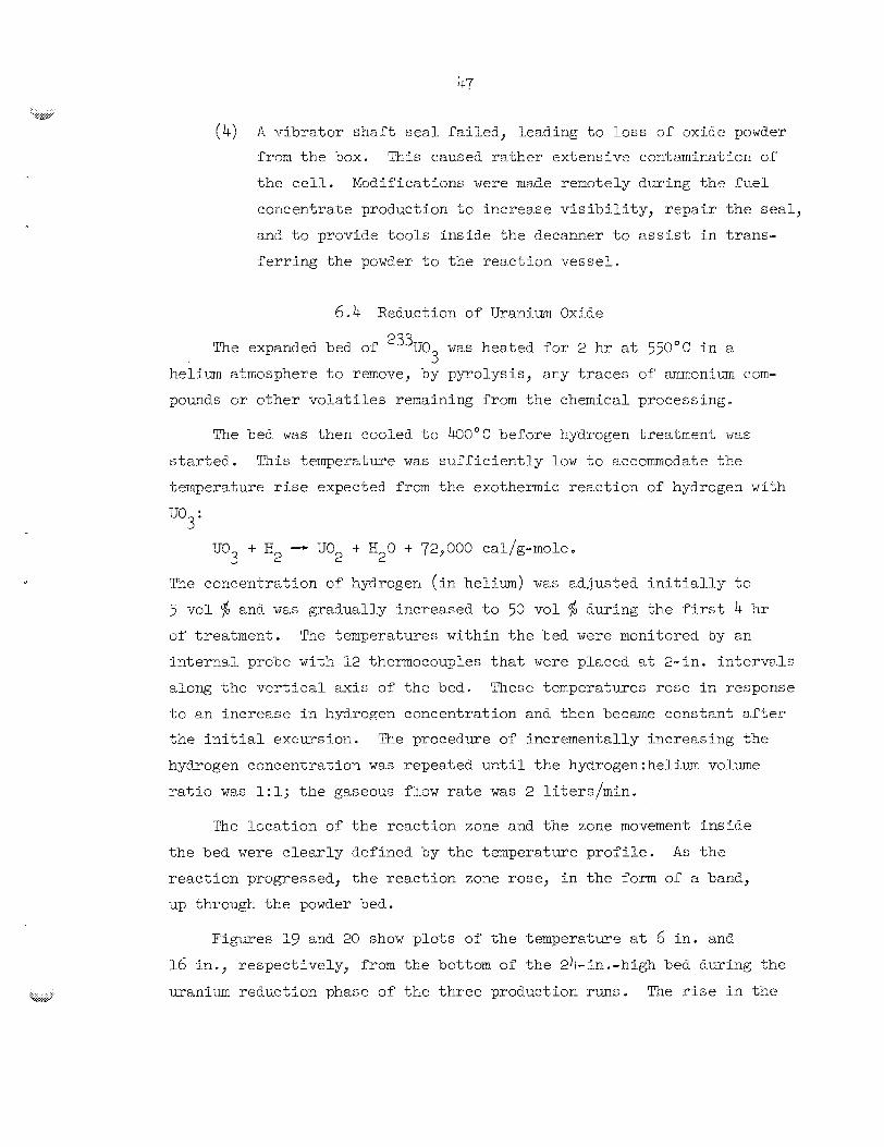
(4) A vibrator shaft seal failed, leading to loss of oxMe powder from the box. This caused rather extensive contaminaticn of
the cell. Modifications were made remotely during the rue1
concentra-be production to increase visibility, repaIr the seal,
and to pro.vide tools inside the decanner to asslist In trans-
ferring the pow3er to the reaction vessel.
6.4 Reduction of Uranium Oxide
The expanded bed of 233U0 was heated for 2 hr at 550°C in a 3 helium atmosphere to remove, by pyrolysis, any traces of ammonium com-
pounds or other volatiles remaining from the chemical processing.
The bed was then ccoled to 4 0 0 ° C before kydrogen treatment waE
started. This temperature was sufficiently low to accommodate tke
temperatwe rise expected from the exothermic reaction of hydrogen with
uo + H~ - uo -+ H o + 72,000 cal/g-mole.
YE? concentration of hydrogen (in helium) was adjusted initially tc 5 vol $ an6 was gradually increased to 50 vo% $J during the Yirst 4 hr of treatment. The temperatures within the bed were monitored by En
internal probe with 12 thermocouples that were placed at 2-in. intervale
along the vertical axis of the bed. These temperatures rose in response
to an increase in hydrogen concentration and then became constsnt after
the initial excursion. The procedure of incrementally increasing the
hydrogen concentration was repeated until the hydrogen:heli-m volume
ratio was 1:l; the gaseous flow rate was 2 liters/min.
3 2 2
The location of the reaction zone and the zone movement inside
the bed were clearly defined by the temperature profile. As the reaction progressed, the reaction zone rose, in the form of a band,
up through the powder bed.
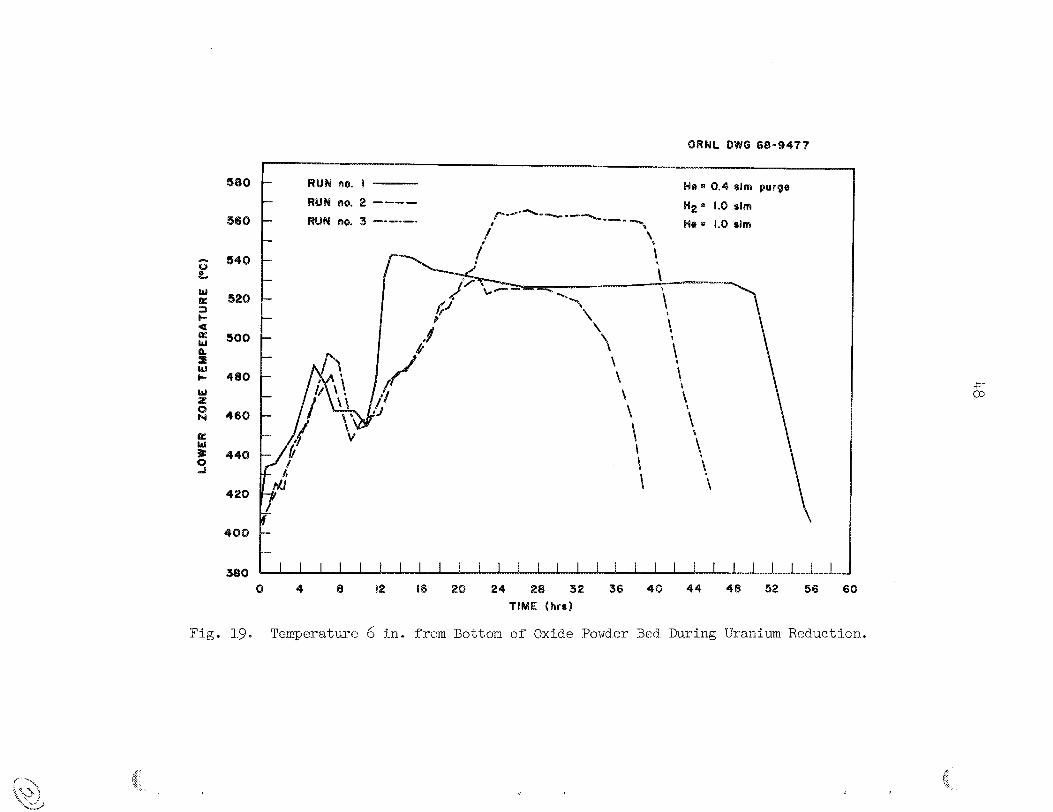
Figures 19 and 20 show plots of the temperature at 6 in. and 16 in., respectively, from the bottom of the 24-in.-high bed during the
mznium rectuction phase of the three production runs. The rise in the
48
8
CQ

49
i
i E I I
[
Ei
I
i
i

temperature of t he lower zone during the f i r s t 8 hr of treatment i s due
t o the exothermic reac t ion ( the reactiora vessel furnace w a s s e t t o con-
t r o l a t h U O ' C ) .
i n i t i a l increases i n hydrogen flow had subsided (approxirnately 12 h r ) ,
t he temperature cf the furnace was increased, a t t h e -ate of 30"C/hr,
u n t i l t he bed temperat-me w e s 525 k 25°C.
continued a t t h i s temperature, with 50 vol 4s hydrogec--50 VOL $ helium, u n t i l 50 t o lo05 excess over t h e s toichiometr ic amount of hydrogen had
keen passed through the bed.
After t he temperature excursion r e s u l t i n g from the
The reduction operat ion w a s
Hydrogen u t i l i z a t i o n within the bed w a s 100% u n t i l t h e reac t ion
zone approached the top of t h e powder bed; then a s l i g h t decrease w a s
observed. Hydrogen usage was determined by a materirtl balznce of t h e
gas flowing i ~ t o the reac t ion vessel, as measured by rotameters, and
t n e gas 0v.6uf10wg as measured by the i n - c e l l wet t e s t meter.
2
Upon coqLLetion of' $he oxi6e reduction s tep, t h e bed was allowed
t o e001 t o 400°C. The conversion of UO t o UF by hydrofluorination,
using IF gas d i l u t e d wZth hycrogen, began a t 400°C and w a s corrpleted
a t 6 2 5 " ~ .
6.5 MydrofEuorination Q Y uo
2 4
Five t o seven days were required for t h e conversion.
The EF gas wzs supplied t o the process by withdrawing it from the
vapor space or a. heated 100-lb IF cylinwer. The cyl inder hea ter was
t h e m o s t e t i c a l l y cont ro l led t o provide 2 vapor pressure t o 12 t o 1 4 psig.
A d i f f e r e n t i a l - p r e s s u r e t r a n s m i t t e r across a c a p i l l a r y r e s t r i c t o r i n
the HF gas supply l i n e w a s used t o monitor the flow. 'The gas was passed
through 2 maze of t i g h t l y packed n i c k e l wire i n a 2-in.-diam n i c k e l tube
t h a t w a s maintained a t 625"~ t o r e ~ o w sulfur from the stream. It vas
then xixed wit'n e xetel-ed amount of dry hydrogen, f i l t e r e d , and in t ro -
duced t o the reac t ion v e s s e l through a d i p tube t h a t extended t o the
bottom of the UO bed. 2
A t t he beginning of' t he hydrofluorination step, t h e composition of
the gas w a s 95 voE $ hydrogen--5 vol $ KF; t he flow r a t e of t h e mixture
w a s 2 s t d l i t e r s /min . Over e period of 3 t o 4 hr, the €IF concentration
w a s incrementally increase5 t o 40 vel $ as the exssherrric r eac t ion
caused ;he bed temperatme t o r;se from
i n i t i a l kours, the temperature within the bed W ~ E constant ly monitcred
t o determtne when the temperature excursion r e su r t ing from esch €E f l o w
adjustment had ceased and when another adjustment could be made e
t o 450°C. During these
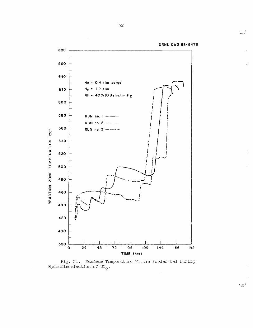
A f t e r t h e %Ip concentration of t he hy6rOfluorimting mixture had
v o l $ j t h e r eec t i cn zone tr,n,veled., i n t h e form of' a band, reached
up throtbgh %he bed ( i n a mnnner s i m i l a r to t h a t observed during t h e
hydrogen reduct ion) 8,s t he UO w a s converted %c T J F The rea.ction 2 4 =
UQ -t 4I.F - -+ 2Hg0 -k 144,COC cal/g-mcle 2
i s acre exothermic than the reduct icn react ion, but E t does not ha,ve as
g rea t a tendency t o cause t h e m a 1 excursions. Probably, this I s t he
r e s u l t of dif ' fereices between U03, U02? and UF4 with respect t o bed
p e m e a b i l l t y end thermal proper t ies e !The react ion- zone temperatures
f o r the th ree production runs are p lo t t ed as a fuac t ion of t i m e i n
Fig. PIo In runs E and 2, severe1 furnace temperature adjustments were
mtde during the f irst f ive days of treatment in an e f f o r t t o i i icreese
the bed temperature to 475-500°C (because t h e KF gas i s l e s s ~o r ros !~ve
t o n l c k e l a t t h e higher tempera.ture).
s a t i s f a c t o r i l y and d id not requi re adjustment.
Ira run 3, t h e fmxnace operateC
The progress of t h e r eac t ion was followed by observing t h e r eac t ion
zone t r ave l through the bed and a l s o by obtaining a material balbnce of
t h e
f irst f i v e dsys and then decreased sharply as the reac t ion zone reached
the top cf t h e bed. 'Then t h e te-nperature of t h e bed w a s increased to 625"C, where it w a s heEd f o r two days t o emure completeness of' t he
r eac t ion . The €IF u t i l i z a t i o n d id not iccreese a t t h e higher temperature;
instead, it continued t o decrease, suggesting t h a t t h e r e e e t i s n had been
complete a t t h e end of t k e f i f t h day cf hydrofluorinat ion.
in t h e system. P - e ET' u t i l i z a t i o n wag e s s e n t i a l l y lOO$ fcr the
A t o t a l of 13.5 kg of uranium, as UO,, w a s converted t o UF i n c IC
each of the three runs; only very minor difyerences i n t he runs were
noted.
686
660
640
6 20
600
580
566
5 48
520
500
480
460
446
420
400
380
RUN no. I - RUN no. 2 - -- RUM no. 3 -P - - -
8 24 48 72 96 120 144 968 192 TIME (hFS)
Ffg. 21. b.lax5m11~ Terriperature Within Powder Bed D x i n g Hydrofluorination of UO,.
L
53
6.6 oma at ion of t he Eutect ic S a l t
The e u t e c t i c mixtwe U F , EiF (27-73 mole $I) (Pig. 22) w a s formed 4- by adding the s to i cho ine t r i c quant i ty of l i t h f m f luorFde rjowd-er t o t he
w a n i u m t e t r a f l u o r f d e powder and fus ing the mixture e
Dry EiF powder w a s a?;,ded t o the reac t ion vesse l by the fcllowing
(1) It was poured -into a hopper located on top s e r i e s of operations:
of t h e decanning s t a t ion , (2) it w a s dumped from the hopper i n t c the decanner box, and ( 3 ) i6, was t r a n s f e r r e d from t h e box t o +,he vessel. by
v ibra t ion and brushing.
The temFe3-ztw-e of t he reac t ion vesse l conta,ining the e t r a t i f i e d
LT4 end LiF powders was then increased t o 855°C i n order t o melt the
i i t h i m f luo r ide (xp, 835°C). t u r e f o r 3 h r vhiLe it wads sparged with hydrogen (a t a f l o w r a t e of C e 2
Piter/rr,in) t o reduce m y extraneous compounds t h a t might kave been
introduced d w i n g ;he L i F addi t ion.
The melt w a s d igested a t ch i s tempera-
A sound detec tor w a s a t tached t o the reac t ion vesse l d ip l i n e t o
sense t h e bubbling of t he hydrogen sparge t h a t would occ1.x i n the
presence of' 2 l i q u i d i n t h e bottom of t h e reac t ion vesse l . 'This was
an exce l len t device for determizing when t h e rneltciow~i had s t a r t e d . The
i n t e r m 1 thermocouple probe confirmed tha t , a t meltdown, a very wide
rnnge 07 temperatures ex is ted along t h e axiz of t h e Ice l t@ A ragiE.
cooldown t o 65C"C w a s observed i n the lower regrion of the vesse l where
l i q u i d ex is ted .
measured i n the upper regions of t h e vessel where Fusing of t he com-
pounds had 2ot ye t taken place. A s more l i q u i d w a s formed, a gradual
shii ' t In t h e temperature pro-f'ile occurred, ind ica t ing a r i s i n g Liquld
l e v e l i n t h e vesse l . The ternperatwe of t h e pool eventual ly reached
850°C~ t h e s e t point of t he furnace temperatme con t ro l l e r .
presence of ?Ae l i q u i d and t he r i s i n g level were also indicated by
changes i n the d ip l i n e p r e s s m e as the back pressure on t h i s l i n e
increased t o overcome the r i s i n g l i q u i d l eve l .
As; t h e sane time, temperatures as high as 859°C were
m e i n i t i a l
Diff'erences, with regard to cofiditions during i n i t i a l mcltdowc,
were noted rn t h e rms, In rsv1s I and 3, the T J F and LiF had t c be 4
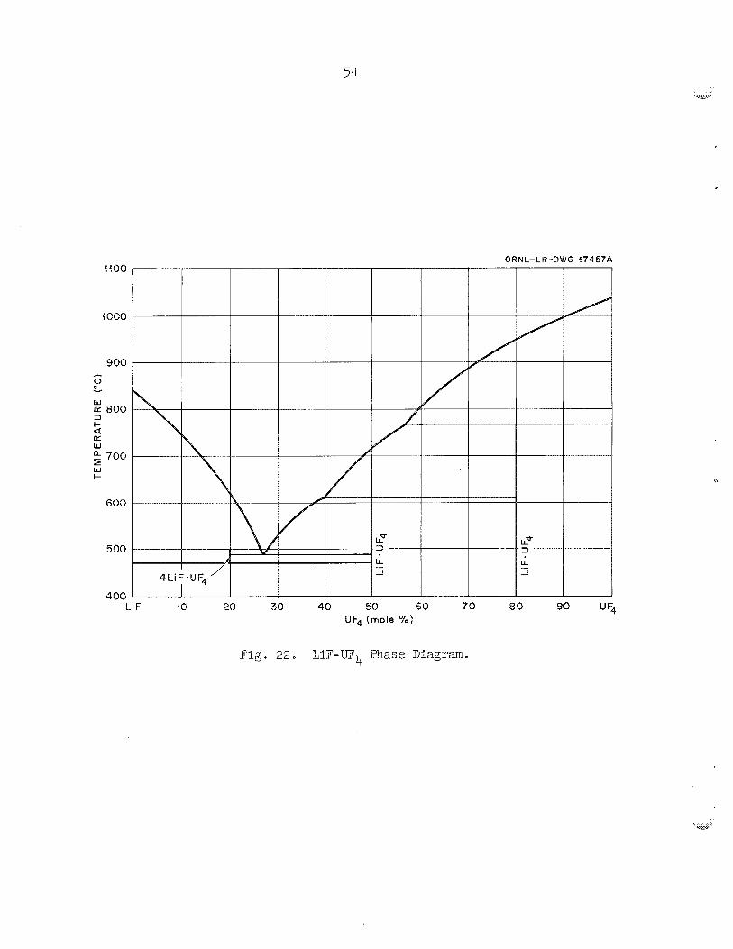
54
ORNL-LW-DWG 47457.4
a0 80 90 "% hi F 40 28 30 40 50 60 UF4 (mole To)
F i g - 22 e LIF-UF €?lase Diagram. 4
55
heated, t o about 850°C: before melting occurred.
melting occurred a t 6 5 ~ " C , near ly 200°C below the x e l t i n g point 07 t h e
L i th im f luo r ide . The low-temperature i n i t i a l melting must have resvl ted
from +,he presence OC a s izable h e e l of s a l t (mpj 4 9 0 ° C ) t h a t remained
i n the reac t ion vesse l from run E. Probably, t h i s h e e l acted as E
"seed" to p e r n i t fusing of t he W and LiF powders a t t he lower tempera-
'ewes
I n rim 2, i n i t i a l
4
The g-in.-deep pool of eu tec t i c s n l t (mp, 4 9 ° C ) w a s next t r e a t e d
wlth 20 v01 $J HF--80 vo l sf0 hydroger ( f l o v r s t e , 2.4 l i t e r s /min ) f o r 2k
h r a t a temperatme of 700°C t o remove the l a s t t r eces of oxide From
the s a l t p r i o r t o the hydrogen p u r l f i e a t i o n procedure. A t the conclu-
s ion of t h i s treatment, an m f i l t e r e d - s ~ x p l e of' t he salt; WE? withcirawn
and analyzed f o r oxide content ' (A 1/25 i n e -OB x 2- E/4- i n * -long n i c k e l
cup was immersed i n ",he sa l t t o withCi3"m a 25-g sample.)
sample had so l id i f i ed : a l-in--long sec t ion w a s cut from t h e c e i t e r 3 r d
analyzed petrographical ly and chemically for i,he presence of UO
remaining por t ion of the sample was submitted for t corcplete chemical
ana lys i s e
After t h e
The 2*
Kydrcger- treatment of t he sal t w a s s t a r t e d p r i o r t o obtaining the
res-dl ts of t he analyses The more r a p i d l y ~ b t t ~ i n e d petrographic r e s - d t s
were =sed t o determine whether hydrofluorination should be resumed o r
whether hydrogen puriPicat ion of the melt should be continued.
of t he th ree runsg the UO content w a s reported to be l e s s than the
lower limit of accuracy (200 ppm) €or t he petrographic appra isa l ; t 'n-~s,
subsequent HF treatment w a s unnecessary. Chemical analyzes of t h e sane
samples showed oxide contents ( i n t h e product sa l ts) of 62, 34, and 32 ppm f o r rans P, 2? and 3 respec t ive ly .
In each
2
6.7 P u r i f i c a t i o n of t he Eutect ic S a l t
The e u t e c t i c s a l t w a s p u r i f i e d by bubbling pure hydrogen gas
( 3 t o 10 ppm H,O), at a flow r a t e of 2 s t d l i ters /min, through the
10-in.-deep melt .
r eac t ion,
L
The temperature of t he molten s a l t during t h l s
-t- l/2 Hg - KF c M',
is 700°C.
effluent gas with the in-cell titration assembly. These data are
plotted in Fig. 2 3 * "he high rates observed initially can be attributed
to the evolution of the soluble KF in the melt. ""ne first inflection
and plateau of each curve correspond to the reduction of the nickel fluoride; this is folEowed by a second inflection and platex,, which
represent the reduction of the iron fluoride. The end point of the
purification was evident from the leveling off of the HF evolution ra te
at 0.025 meq per liter of hydrogen. The hydrogen flow rate was in-
creased on several occasions during the process, an6 the reaction rete
seemed to be almost Lndependent of the hydrogen concentration.
'The progress of the reaction was followed by titrating the
The effect cf the hydrogen treatment on the concentration of the
corrosion products is shown in Table 5 . The chromium concectration in
the melt was no t affected by the hydrogen treatrrent. Highey i n i t i p -1
values of nickel in the thk-6 rung and of" iron in the second znd third
rms, were the resxl t of residual lnateriab left i a r the bottom of the
reac-b-ion vessel from previous runs. Apparently, the metals had pre-
cipitated and thus hzd not been filtered eut during the transfer
operetion.
The levels to which the iron and nickel concentrations were lowered by the hydrogel? reduction of the metal fluorides ere believed to be
near the linit of accuracy of ?he sampling eysten; and the laboratory
analyses. The act;mb concentrations of' these impurities in the en-
richi9g concentrate, as delivered to the IfSRE, should be somewhat lower
tian the values reported because an additional 24 hr of hydrogen treat- ment; was provided in each run after the filtered samples were withdram
for analysis.
to the 1LZSF.E; Table 7 gives the isotcpic analysis of the uranium. Table 6 gives the chemical analyses of the fuel shipments
During each of the three runs, the reaction vessel was exposed f o r
2C days to 40 vel % HT--6C vo1 $ hydrogen at temperatures ranging fron 4-00 to 850°C. the reaction vessel) was lost to each melt.
uniform corrosion rate of slightly less than 0.001 in./yes,r - a low
Approximately 5 g o f nickel (from the Kickel liner of
mis corresponds to z
r ~ t e for this type of process.

e 11
0.18
0.16
0.84
0.86
0.04
0.02
6.00
RUN no. I -
RUN no. 2 -- - -
RUM no. 3 -----
-
-
- ---e -----
- ---- --------_____
.- 1 I I I / I
24 48 72 96 120 144 168 192 216
TIME (ha)
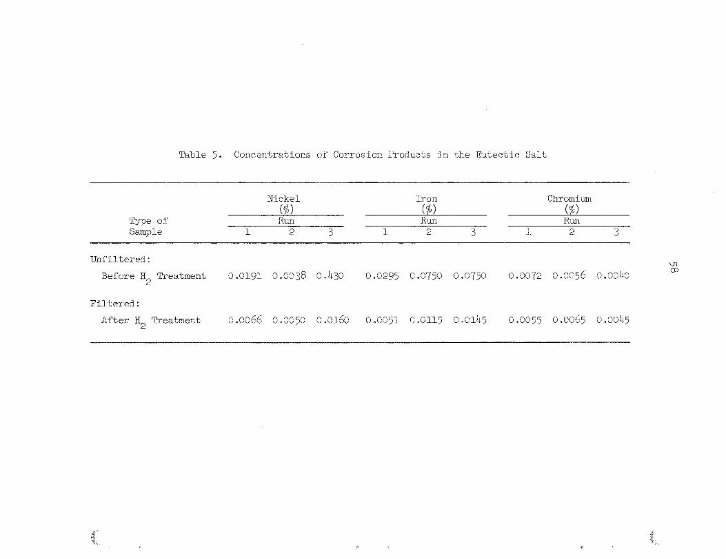
Table 5* Concentrations of Corrosian Products in the fitectic Salt,
Nickel IrOll ChI-OTllil.,lXl (4> @> W
Type of Run Run Run Sample 1 2 3 l 2 3 1 2 3
wnfiltered.:
Before W2 Treatment o.olgl 0.0038 0.430 0.0295 0.07yl 0.0750 0.0072 o.oc56 0.0040
Filtered:
After W2 Treatment 0.0066 0.0050 0.0160 0.0051 c.0115 0.0145 0.005~ 01.Q065 0.0045

Table 6. Analyses" of the 233, 4-7LiF (27-63 mole $) Fuel Concentrate
Cans B, C, D, a.nd E Capsules (45) cam F, B, J, L, w, P Chemical Spectrographic Ckremical Spectrographic Chemical Spectrographic
Element ti Anal-sis Analysis Analysis Anal sis Analysis
Al.
A
Cd
CC?
Cr
CU
Fe
cd.
Li
Mxl
MO
Ni
O2 l-b
EL-
si
S
sm
Sn
Ti
0 .ooy
0.0104
0.0082
42 ppm
< 0.01
< 0.004
< 0.033 < o.oce
0 d-7
< 0.003
4.83 < o.oco4
< 0.004 < 0.04
< 0.030
< 20 ppm
< 0.007
< 0.032
c.0055
0.0051.
0 -0066
52 ppm
< 20 ppm
0.0045
0.0145
0.01.63
32 xv
< 0.01
< 0.004
< 0.021
< 0.002
< 0.004
< 0.002
4.91 < o.coo4
< 0.004 < 0.002
< 0.010 < c.038
< 20 ppm
< 0.004
< 0.002
V
zn c 0.002 < '3 .ow
u 64.38 61.8 63 m 1.9
< 0.038 < 0.01
< 0.09
< o.oc\lc 4.8
< 0.09
< 0.008
aIn wt $ unnless given in ppm.
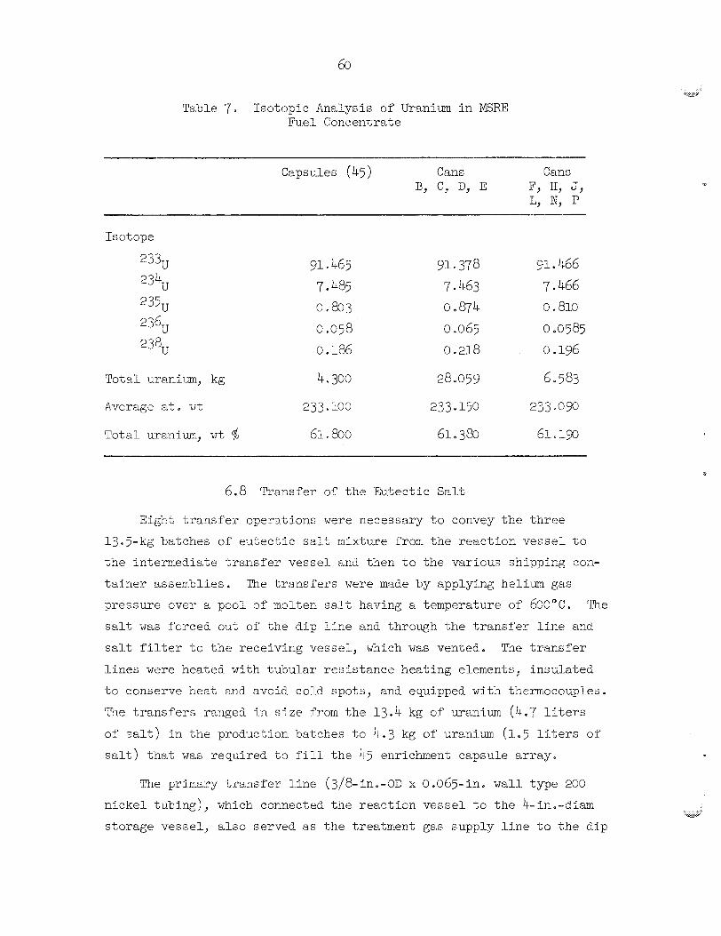
60
Table 7 . Isotoplc Analysis of Uranium i n MSRE Fuel Concentrate
Capsules (45) Cans Cans
Tot21 uranium, kg
Average a t m
Total uranium, w t $
4 P 300
233 103
91 a 378 7.463 0.874 o .065 0.218
28.ogg
91 * 466 7.466 0 s 810
0.0585 0.196
6 583
6.8 Trarisfer of' t he Eutect ic Salt
Eight t r a n s f e r spe r s t i sns were necessary t o convey the th ree
13.5-kg batches o f eu tec t i c ~ a l t rnixture from the reackion v e s s e l t o
t h e lc temiediate t r a n s f e r vesse l and then to t he various shipping con-
t a i n e r assemblies. The t r anz fe r s were made by applying helium gas
pressure cver EL pool of lraoitea salt having a temperature sf 6GO"C.
sa l t w a s forced out of the d i p l i n e and thrcugh the t r a n s f e r Line a d
sa l t f i l t e r t c t h e receiving vessel , vhich was vented. The t r a n s f e r
l i n e s were heated with tubular r e s i s t a n c e heat ing elements, insu la ted
t 6 conserve heat acd avorEd cold spots , and equipped with them-ocoq les .
m e t r a n s f e r s ranged i n s i z e from the 13.4 kg o f T a - a r , i u m (4.7 l i t e r s
of s a l t ) Sn t h e production batches t o 4.3 kg of ua-aniLun (1.5 l i t e r s of
s a l t ) t h a t was reqGired t o f i l l the 45 enrichment capsule array.
The
"?he primary t r a n s f e r bine ( 3 / 8 - i n . - o ~ x 0.065-in. wall type 200
nicke l tubing)
storage vessel , a l s o served as the treatment gas supply l i n e t o t h e Uip
which connected the r e a c t i a n v e s s e l t o the b=-in.-diam
Y
tube i n the reac t ion vesse l . During the processing cperations, t h i s
l i n e w a s ccnnected t o t h e t r ea t aen t gas supply l i n e instead of t he
t r a n s f e r vesse l . In each of the feed batch t r m s f e r s J a compression-
type f ' i t t i ng had to be broken and the t r a n s f e r Line had t c be zonnected
t o iL new salt f i l t e r t h a t had previously been i n s t a l l e d i n a nozzle
atop the s5orage vesse l . '&e s l r t e r e d n icke l f i l t e r was 3 i n , i n
diameter, and the pore s i z e W E S 20 p . Transfers t h r o q h t h i s l i n e re-
quired an overpressure of E5 psig t o overcome t h e s t a t i c head (18 f t
H,O) and the r e s t r i c t i o n t o flow of the f i l t e r .
plete t h e t r a n s f e r varfe? ~ r o m 78 t o 140 m i n .
salt through the l i n e was obvious from the r a p i d response of t he atteched
t h e ~ ~ ~ o ~ o ~ p l e s t o the salt temperat-=e. The progress of t he t r a n s f e r
w a s followed by observing the r l s i c g back pressure ec t he h e l i m purge
t o the s torage vesse l dip l i n e ; t h i s indicated a r i s i n g l i qu id l e v e l .
The rrrsh of gas through the l i n e a t the end of t he t r a n s f e r w a s s u d - i b l e
from the sound de tec tor . These conditions were v e r i f i e d by a sharp
drop i n the r e a c t i o n vesse l pressure and a rap id increase i n gas flow
through the s a l t t r a n s f e r l i n e .
Time reqdired t o com-
I n i t i a l movement of t h e
Five t r a n s f e r s were reqdired t o f i l l the three-pro6xct container
assemblies.
connected the assembly t o a d i p l i n e i n the s torage vesse l . Since
f i l t e r s were not Tnvolved i l z these t r ans fe r s , the trarsfers were com-
p le ted i n approximately 10 m i n . a"nermccsup1es cn t he krransfer line and
on the shipping containers indicated the movement o f sa l t . An cverflsw
pot a t t h e end of the containers ( i n s e r i e s ) w a s equipped with Liqrrid
l e v e l de tec t ion probes and i n t e r n a l thermocouples t o ind ica te the pres-
ence of s a l t . A blowbsck of gas then ens-xed t h a t t he containers were
f i l l e d t o the proper l eve l .
They were made v i a a l/h-in.-OD nicke l t r a n s f e r Pine th2-t
The t r a n s f e r operations were conducted a t a sa l t temperature of
600°C.
t a i n e r s had been fabr ica ted t o contain the desired quant i ty of f u e l a t
t h i s temperature. )
salt w a s allowed t o s o l i d i f y before t h e disassembly operat icn began.
(This temperature had been a r b i t r a r i l y selected, and the COP-
The filled containers were allowed t o cocl, and the

62
6.9 Container Disassembly and Preparation for Shipment
The shipping container assemblies were stripped of the themo-
couples, overflow pots, heaters, and suppcrting harcware. The containers
were separated from each other by cutting the interconnectiag tubing.
The 45 enriching capsules were clipped and trimmed, were tested (i.e-, their lifting bai ls were tested) with a l 5 - l b pull, were drilled
for drainfng aad venting, and were identified and weighed. were packaged, in groups of six, in carrousel shipping containers. The
equipment, whlch was designed to do these operations remotely, fumtioned
satisfactorily.
Then they
The 2-1/2-in.-diam product cans were easi%jr removed from the filling
arrays; however, removal of the top and bottcm plugs from each can was
quite difficult. An inordinate amount of' force was necessary to break the bottom plug loose tram the thin salt film that had formed in the
annulus between the plug and the bottom nozzle. Several fixtures Ce-
signed for this task proved to be inedequate and had to be replaced with
stcrdier units. A liPting bail. was installed on each can?. A l s ~ , a
stopper was inserted in the bcktorn of the can to rriinimize the loss of
salt dwirig handling and shipment.
The cans were weighed by using a beam balance that was located in
a glove box mounted cn top of the processing sell.
came a part ef the cell containment for this operation. A long cable,
with the lifting b a i l of the can attached, was sTJspended from the
balance into the cell.
to 15 kg.
'%he glove box be-
The gross weight of the cans ranged from le6
ALL of the shipping containers were t h e 3 stored in cell G to await
shipment tc the XSRE.
6.1~ Transfer of 7 LiF-233W4 Salt Product to the MSRE
Six of the 2- %/2- in a -diarn product salt containers (total uranium
content, 33 kg) were delivered, iidividually, to t h e MSRE In the E9-tan
fi-AB carrier. ?"ne Pu-A1 carrier wes slightly modified Per this opera-
tion. The three-barrel magazine was removed, and a winch-and-cable
assembly w a s i n s t a l l e d on top of the c a r r i e r i n a. sealed kousing so
t h a t it S e c m e a p a r t of t he c a r r i e r containTrect.
The c a r r l e r w a s placed on top ot' t he pedes ta l over a 6-in0-diam
por t t o c e l l G, and beeme a p a r t of t h e c e l l containment when the
s l i d e drawers i n botk the c a r r i e r and t he pedes ta l were opened. %e
cable hook w a s lowered i n t o the c e l l t o receive the product can and
then r a i s e 2 t o withdraw the can from the c e l l i n t o the c a r r i e r . The
pedes ta l drawer and the c e r r i e r drawer were closed, i s o l a t i n g the car-
r i e r arid cell from each other and from the a m l e n t atxosphere. In t h i s
manner, containment of' the fuel was malntained a t a.lb t i m e s . Tk-e car-
r i e r w a s then rerm.,oved from the pedestal , sezled by t h e i n s t a l l a t i o r of
t he cover p la tes , and cleaned of any surface contaEination.
The f u e l c a r r i e r w a s then t ransported t o the PISRE, where it w&s
posit ioned over a t u r n t a b l e (Fig. 24) t h a t 'was designed for charging
the enriching concentrate t o the r e a c t o r f u e l dra in tank. 6
Neasurements, a t t he sm-face of the %-A1 ca r r i e r , of t he r a d i a t i c n
The neutrons emit5ed by one 7-kg i r a n i w f u e l ca.n are given i n T3bHe 8. a.re produced by (a,?) r e a x t i o m on l i th ium and f l u o r i n e (of t h e e c t e e t i c )
by the high-energy alpha p a r t i c l e s emitted by s e v e r a l of the daughters o f t he 23ZU
The enrichment capsules were shipped t c the IGRE i n a smxller
c a r r i e y t h a t was designee. t o accommodate s i x c2psules i n a car rouse l
f i x t u r e , "he car rouse l served as a support f i x t u r e during t ranspor t
and as a holder f o r s i x bottom plug assemblies t h a t became a, pa r t of
t he sampler - enricher system a t the WWE as t he capsules were removed
€ r o m the c a r r i e r through a l-l/2-ine-dLam hole Ln t he top.
A small glove box w a s fabr ica ted f o r use i n removing the car rouse l
assenbliee from c e l l G. This box w a s mounted on top of t he snall car-
r i e r , whichg i n turn, was mounted on t h e pedes ta l above t h e c e l l . Then
the pedes ta l s l ide-valve drawer w a s opened, and the glove box and the
c a r r i e r became a part of the cell containment. A cable from a winch
ins ide the box w a s Powered i n t o the cell t o receive t h e car rouse l . The
c a r r o w e l was withdrawn i n t o the c a r r i e r , the pedes ta l Crawer was closed,
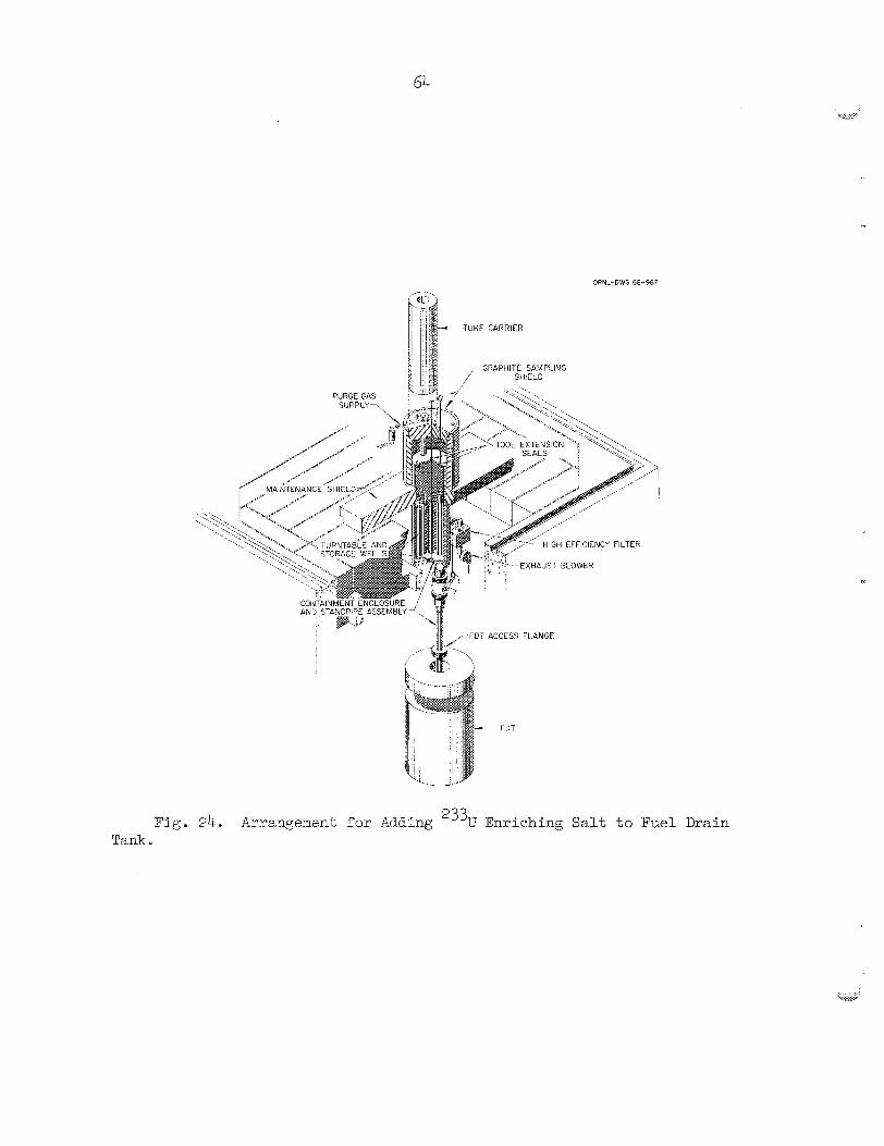
64
ORNL-DWS 68-367
- TURF CARRIER
GRAPHITE SAMPLING
--EXHAUST BLO'WER
Fig. 24* Arrangement for Adding 233U Enriching Salt to Fuel Drain Tar&
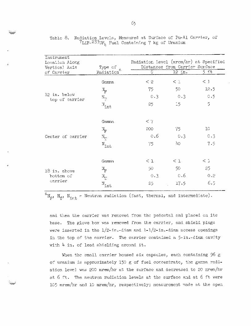
d
Table 8. Radiation Levels, Measured at 7LiF.-*%TFk Fuel containing
Surface of Pu-A1 Carrier, of 7 kg of iTrenim
Ins tr-mext Location Along Radiation Level (m-em/hr) at Specified
Type of Distances frorx Cerrier Surface of Carrier Radiation 0 12 in. 5 f't Vertical *Axis a
12 in. below top of carrier
Center of c a r r i e r
ITm 1
'int
2'00 75 HO MT o 6 0.3 c: c 3
Nint 75 40 7.5
Gama
18 in. zbove NF bottom of
a NTJ Nint = Neutron radiation (fast, thermal, and intermediate)
and then the carrier was removed from the pedestal and placed on i t s
base. The glove box was removed from the carrier, and shield plugs
were inserted in the 1/2-in.-diam and 1-1/2-in.-diam access openings
in the top of the carrier. with 4 in. of lead shielding around it.
The carrier contaEned a 5-in.-dim cavity
When the mall carrier housed s i x capsules, each containing 96 Q
of' uranium in approximately 150 g of fuel concentrate, the gamma radi-
ation level was 200 mrem/hr at the surface and decreased to 2C mrem/hr
at 6 ft. The neutron radiation levels at the surface and at 6 ft were 105 mrem/hr and 10 msem/hr, respectively; -measurement made at the open
66
bettom of the c a r r i e r during removal from t h e pedes ta l indicated s:
r a d i a t i o n l e v e l of 50,000 mremlhr
The removal of t he f u e l From c e l l G and i t s su5sequent t r a n s f e r
t o the MSRE were character ized by very bow r a 2 i a t i o n exposmes t o
personnel snd e s s e n t i s l l y no spread of contamination. In f a c t , only
the top surface of the pedes ta l and a s m a l l a rea immediately adjacent
t o it had t o be deconte,minateZ.
A t o t a l of 39-72 kg of uranium, in t he form of uranivzq oxide
powder, w a s t ransrex-ed t o c e l l G of t h e TURF. O f thLs amcmt, 38.95 kg 0: uran im, as EiP-W4, w a s packaged as the f in i shed prod-xt .
The can-opening operat ion accounted f o r e l o s s of 245 Q of uranium
as =xanium oxide. Most or' t h i s , 200 g, w a s l o s t throillgh the empty can
discharge chute because excessive powder had accumulated ic t he box. A
leaking seal on the v ibra tory Ecreen dr ive sha f t accoluited f o r 45 g e
Remote rns6ification t o the decannifig s t a t i o n and changes i n operating
procedures elPminated these sources of EQSS a f t e r t he fClrst batch (29 o x ~ c ~ e cans) had been processed.
Sampling accounted f o r a loss of 1c)C g of xranim. TI.TS 15-g and
two 5 - g salt samples were required i n each of t h ree proeaetion runs.
I n adc?ition, severa l e x t r e samples were required f o r s p e c i a l purposes.
The presence of hee ls i n ce r t a in vesse ls and the holdup i n t r a n s f e r
l i n e s and f i l t e r s were responsible f o r t h e ma jo r i ty of t h e loss. The
h e e l i n the reac t ion v e s s e l axounted t o 27 Q . H o k w ~ ~ : the s torage
-~esse l contained 346 Q of u r a n i m as h e e l as e r e s u l t of a d i p l i n e
replacement. #The d ip l i n e IELS i n s t a l l e d improperly znd, as a r e s u l t ,
about b/a i n . of unrecoverable s a l t heel w a s l e f t i n t he vessel.
A sumnary of the uranium accountabi l i ty i s given i n Table 9.
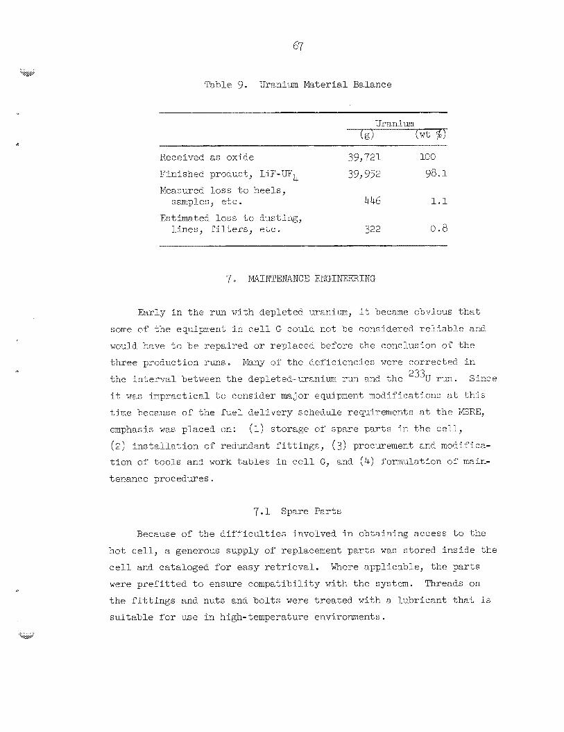
Table 9 Uranium MaterLaE Balance
Uranium
receive^ as oxide 399 721 100
Finisher; prcduct, LiP-up4 39,952 98.1 Measured l o s s to heels ,
E s t h a t e d l o s s t o Austing,
s aq le s , e t c . 4 46 1.1
bines, f i l t e r s , e t c e 322 0 .8
Early i n the run with depleted uranium, it Seczme obv io7~s t h t
some of che equi-pent in c e l l G could not 3e considered relLable end
worzld have to he repaired o r replaced before the conclusion of t h e
th ree production rms. Many of t he def ic ienc ies were corrected i n
the lnterval between t h e depleted-uranium run an2 ",e 2'3U r-m.
it W&E imprac t ica l t o consider major equipment modificatfons a t this
t i m e beceuse of t h e f u e l de l ivery schedule requirements a t t he !GREY
emphasis w a s placed on:
(2) i n s t a l l a t i o n of redw-ciant f i t t i n g e , (3) procurement zslrt moclifica-
tion of t o o i s and work tables i n c e l l G, and (4 ) Torrimlation of rnaln-
tenance procedures.
r ?
Since
(1) storage of spare pa r t s i n t h e c e l l ,
7 .1 Spare Par t s
Because of t h e d i f f i c u l t i e s involved i n obtaining access to %ne
hot c e l l , a generotbs supply o f replacement p a r t s w a s s tored in s ide the
c e l l and cataloged for easy r e t r i e v a l . Where appl icable , t he p a r t s
were prefitr led t o ensure compatibi l i ty with t h e system. Threads on
the f i t t i n g s and nuts an6 b o l t s were t r e a t e d with a l ab r i can t tha.'; i s
su i t ab le for use i n high-temp%rature envi roments .
7.2 Redundant F i t t i n g s
The compression-type f i t t i n g s used on the sa l t t r a n s f e r l i n e s and
on the gas supply l i n e s a t the vesse l nozzles were extremely d i f f i c u l t
t o make and 'break a f t e r they had been thermally cycled fro^ room tempera-
t u r e t o 600-700"~. f i t t i n g s made the operation even more d-iff'icult because t h e s a l t formed
a s e a l around the protrusion of t h e tubing i n t o the f i t t i n g .
several of theee f i t t i n g s had t o be r o u t i r e l y operated i n t h e produet
t r a n s f e r operations, there were severa l l i n e s i n the system f o r which
no a l t e r n a t e had been provided. I n t'nese cases, redundark F i t t i n g s
vere i n s t a l l e d i n such a manner t h a t a second fL t t ing w a s avzilable i f
t h e primary f i t t i n g could not be operated.
arrangements a r e normally conducive t o leakage, 30 such problems were
enccuntered here. On two occasions, use of t he standby f i t t i n g vas
necessary i n order t o replace the s i n t e r e d metal f i l t e r i n t h e s a l t
t rans fer l i n e
The passage o f molten salt t l a ro~~gh one o f these
Since
Although complex f i t t i n g
7.3 Tools and Work Tables
A l a rge assortment of hand tools , modified f o r use with the arianip-
u l s to r s , were s tored on t o o l racks i n the c e l l .
consis ted of welding g r ips t o the t o o l t o a i d i n handling by the nester-
s lave manipulators. A few special-purpose too l s , such as air-operated
snips ( f o r cu t t i ng the interconnecting tubing of t he capsules) and an
impact wrench ( f o r use with t h e electromechanical manipulator)
a l s o s tored €or l a t e r use i n the cell. End wrenches and o ther fixed-
s i z e too l s were color coded by s i z e s for ease i n i d e n t i f i c a t i o n .
Usually t h e modification
were
Work tables and t r ays were located between t h e viewing windows
and t'ne major pieces of equipnent. m e y p ~ o v e d t o be invaluable i n t'ne
many mechanical and maintenance operations conducted i n t h e th ree salt
productlon r m s because of t he l imi ted reach of t he master-slave manip-
u l a to r s and a l s o because of t he l imi ted riel& of v i s ion a v a i l a b l e through
the windows. A secondary, but very important, funct ion of t he t r a y s
involved r e t r i e v a l of t o o l s and miscellaneous items t h a t were dropped
because of wear of Eanipulator p a r t s o r because of ewkwardness on the
c
p a r t of t he operator . When an item f e l l t o the floor, r a t h e r than
onto a t ray , it usua l ly had t o be rep.'iaced si.nce r e t r i e v a l from the f l o o r i n rrany loca t ions of t h e c e l l w a s irrpossible.
The k r g e heavy-duty work tabbe (P4g. 19) designed €or t h e prod-x t
container and capsule a r r a y disassembly operations served 7*rePE i n tkese
func",icns and w a s also used extensively as a general-purpose work bench.
7 .4 Maintenance Procedures
Remote maintenence o€ t h e procecE eq-Jipmcnt was recognized, dming
t h e run with depleted uranium, t o be a fomid?uble t a s k t h a t collld not
be l e f t t o t h e opera tor ' s d i sc re t ion when the nee? a rose . 3 u s an
engineer was assigned, on a full-t lme bas is , t o develop detaileci mhin-
tenance proceclurcs thak vould be appl icable during any conceivable
Fa i lure as well as d w i c g t h e planned maincenznce operat icns e
A comprehensive s e t of close-up photographs was teken of tt:c
e q u i p e n t i n cell G before t h e c e l l was sealec t o process %he rad ioac t ive
material. These were l a t e r sJ@uentec by photographs taken through t h e
Ehielding windows and t he rr_or,ocular viewers Altogether, mere thac 300
photographs were rnarje.
Fif$y-fi.ve de ta i led , step-by-step rmintenance procedures were
wr i t t en by - s i n g the photographs and f i e l d sketches (more than 300)
thzt had been .used I n t h e f&hr ica t ion and. i n s t a l k t i o n of the equip-
nent. A comapletc list of? t o o l s and mater ia l s necessary f o r t he job was
included i n each procedrxre -!&ere appropriate , the maintenance proce-
dure was r e fe r r ed t o , o r included in, an operat ing procedure t o ensure
cont inui ty of' a process operat ion. Although it w a s not necessary t o
use a l l of these procedures i n t h e fuel production, they were i n s t r u -
n e n t a l i n ensuring a safe and order ly completion of t b i s task.
8 CQMCLUSIOKS
r r
1. Reactor-grade e i l tec t ic salt concentrate, 7LiF-23JLTb (73-27 r33, P'
4 mole $), cnaa be prepered by reaote ir,eans f r o m LIF and rJ3UOr o r 2 3y t h e process described ric t 'nZ~ r epor t .
2- Hydrogen reduction and hydrofluorination reaction rates of
oxide beds can be controlled satisfactorily by adjusting hydrogen and
flows to avoid excessive temperature excursions from the exothermic reactions involved. Temperatures can be determined by placing a number
of thermocouples within the beds.
3 . Ecpipment for a remote process of this t y p e should be designed
with a minimum number of close-tolerance fits. It should also be de-
signed on a modular concept SO that components car, easily be replaced,
thus eliminating, if possible,, remote repair operations.
4. In general, commercial pipe, tubing, and electrical fittings
are satisfactory in this type of operation. However, they are not
satisfactory in instances where high temperatures or exposure to molten
salt are expected. In these cases, special-purpose fittings should be developed.
5. Concentrations ~f the corrosion products nickel and iron can
Se reduced to satisfactorily low levels by hydrogen treatment of molten szlt at 550°C. Chromium was not reduced by the process described.
6. A blnary mixtme of UF4-EiF having a eutectic composition can
be fused at a temperature of 650°C in the presence of a small mioauat of'
liquid eutectic heel remaining in a vessel. In the absence of the Eiq-
uid heel, it is necessary to heat the materials to the melting point
of' the LiF (835°C) to achieve liquefactl ion.
7 . T c cbtain a product containing less than b ppm of oxygen and to avoid plugging of dip lines by t'ne formation of' oxides within them, it w z s necessary to install e @ata.ly-bic recombiner and a molecular-
sieve drying column in %he hydrogen supply system. 'The use of Einde
rype 41.4 1/16-:~-di~m sieve material in a regenerative drying co~unn
retimed the rnoistixe content of commercial-grade hydrogen to less than
3 PPm.
8 . bintenance procedures are necessary to ensure orderly corn-
pletion of a process of this nature. They are vital when entry into a
contaminated cell is necessary and when equipment and the product must be removed from the cell.
71
The aukhors express $heir appreciat ion t o %he following persons
whose assis tar ,ce w a s e s s e n t i a l t o t h e successfu l preparat ion of t he
enrichTng 2331J rue1 concentrate for t h c ?ISRE:
J H. Shaffer (Reactor Chemistl-y Division) f o r process development;
E. E. Nicholson and W. F. Schaffer, Jr., f o r process equulpinent cleslign;
S. Iknn f o r a s s i s t ance i n operations arid data ana lys i s ; J. 1. Jarvis
(cn 1oa.n t o t h e Metals and Ceramics Division f r o a t h e General Engineer-
ing Division) for process eqxipment i n s t a l l a t i o n and msdificacion, and
for cieveboplnent of mainteneme procedures; acd 3. W. Anderson end
B. M e Shep'nerd (both of whom are or? loan t o t h e Metals and Ceramics
Division from the General Engineering Division) f o r f ~ ~ c f l i t y cngineerfng
a.nd supportling serv ices a
G. I. Cathers and
10. REFEF.ENCES
P o N. Haubenreizh, p r iva t e cornmica t ion , Beceanber 1966
J. 3. Engel, I'ERE Design and Operations Report, Fart XI-A,
ORhT-TM-2304 (September 1968)
Chem. Tech. Biv. Ann. Progr. Rept., I%y 312 1968, ORNk-1~2.72,
pp. 28-33.
J. W. Anderson and J. 6.1. Chandler, Safe ty Analysis for the Thorium-
Uranium Recycle F a c i l i t y (TURF), Building 793C, OBI%-4278 ( t o be
published) e
C. J. Barton e t ab., "Phase Equi l ibr ia i n the Alka l i Fluoride-
Uranium Tet ra f luor ide Fused S a l t Systems," J. he Ceram. S O ~ . ,
- 41(2), 43-69 (1958)
--
P. N. Haiiber-retch e t al., MSRE Design and Operations Report,
Pa r t V-A, %:&fety Analysis of Operations with 233U, ORHL-TM-2211
(February 19681, p. 37.
--
...... ..?

P
73
CRNL-4 37 1 uc-80 - Reector Technology
IMTERNAL DISY'RIBUTIOM
1, Biology Library 2-4 ~ Centsrel Research Library 5-6. ORNL - Y-12 Technical Library
Document Reference Section 7-41. Laboratory Records Department
42. Laboratory Records, ORNL R . C . 43. R. G. A f f e l 44. J. L. Anderson 45 . J . W. Anderson 46. C . F. Baes 47* S, E, Beall 48. M. Bender 49. E . s . Bettis 50. E , G. Bohlnan 51. S, E " Bobt 52. G. E. Boyd 53, R. E. Briggs 54. R . E , Brooksbank 5 5 . W. B. Burch 56. W. 9. Carr 57. G . 3 . Cathers
58-59. J, M, Chandler 60. F. L. Cul l e r , Jr. 61. S. J. D i t t o 62. W. P, Eatherly 63. 3 . 8. Engel 64. D . E . Ferguson 6 5 . E. M. ~erria 66. J . PI Frye, Jr. 67. 8. E . Gehlbach 68* W. R. Grimes 69. A. G . Grindel l 78. R. G . Gumon 71. P a x'. Saubenreich 72. 74. H. Jordan 73. P. R. Kasten 74, J . W . Moger 95. C . E. Lanib
76. C. E. Larson 77. M. H. Lin 78. R. €3. Lindauer 79, A . F. Litman 80. A . E . L o t t s 81. M. Lundfn 82. PI. G. MacPherson 83. R . E . MacPhe- w o n 84. S, Mann 85. H. E . McCoy 86. J, R . McWherter 87. R. L. Moore 88. J e P. Nichols 89. E. L . Nicholson 90. A . S . Meyer 91. A . M. Perry
92-93. M. W. Rosentha1 94. Bunlap Scot t 95. W . F. Schaffer 96. J . E . Shaffer 97. 37. J. Skinner 98. J. W. Snider 99. B. A . Sundberg 100. R, E. Thcmna 181. W. E. Unger 182. J - E. Van Cleve, 3r- 103. A . ?Im Weinberg 104. J . E, Weir 1 0 5 . M. E . whatley 106. G . M. Watson 107. J . C . White 108. R . G. Wper 109. Gale Young 110. J. L. youngblood 111. P. H. m e t t ( consu l t an t ) 112. J. J. K a t z ( consu l t an t ) 113. J . L Margrave (consul tant 1 Elk. E . A . Mason ( consu l t an t ) 115. R . B. Richards ( consu l t an t )
EXTERNAL DISTRIXJTION
(. .. . . . . . .-
116. D, E. BloomfiePd, Battelle-Northwest, Richland, Washington 117. J . A , Swartout, Union Carbide Corporation, New York 118. Laboratory and University Division, AEC, OR0
119-338. Given d i s t r i b u t i o n as shown i n TID-4500 under Reactor Technology category (25 copies - CFSTI)