Embed Size (px)
Citation preview

MINISTRY OF INDUSTRY JAPAN INTERNATIONAL AND COMMERCE (MOIC) COOPERATION AGENCY (JICA)
PREPARATORY SURVEY ON INDUSTRIAL ZONE DEVELOPMENT IN
THE LAO PEOPLE’S DEMOCRATIC REPUBLIC
FINAL REPORTPART III
FEASIBILITY STUDY FOR VIENTIANE INDUSTRIAL PARK
JUNE 2010
NIPPON KOEI CO., LTD. INTERNATIONAL DEVELOPMENT CENTER OF JAPAN
MINTECH CONSULTANTS INC.
JUN
E 2010
PR
EPA
RATO
RY
SU
RV
EY
ON
IN
DU
STR
IAL ZO
NE
DE
VE
LOP
ME
NT IN
TH
E LA
O P
EO
PLE
’S D
EM
OC
RATIC
RE
PU
BLIC
FINA
L RE
PO
RT PA
RT III
FEA
SIB
ILITY STU
DY FO
R
VIE
NTIA
NE
IND
US
TRIA
L PAR
K
IDD
CR(3)
10 - 043
No.

MINISTRY OF INDUSTRY JAPAN INTERNATIONAL AND COMMERCE (MOIC) COOPERATION AGENCY (JICA)
PREPARATORY SURVEY ON INDUSTRIAL ZONE DEVELOPMENT IN
THE LAO PEOPLE’S DEMOCRATIC REPUBLIC
FINAL REPORT PART III
FEASIBILITY STUDY FOR VIENTIANE INDUSTRIAL PARK
JUNE 2010
NIPPON KOEI CO., LTD. INTERNATIONAL DEVELOPMENT CENTER OF JAPAN
MINTECH CONSULTANTS INC.

THE EXCHANGE RATES USED IN THE REPORT ARE:
USD 1 = JPY 90.52
LAK 1 = JPY 0.01

Survey Area for a Basic Plan (Whole of the Lao PDR)

III-i
Preparatory Survey on
Industrial Zone Development in
the Lao People’s Democratic Republic
Final Report
Part III: Feasibility Study for Vientiane Industrial Park
Table of Contents Page
CHAPTER 1 RATIONALE FOR INDUSTRIAL PARK DEVELOPMENT IN VIENTIANE..........III-1-1 1.1 Background of Industrial Park Development in Vientiane..............................................III-1-1
1.1.1 Study on Industrial Area Development (IAD) Scenario..............................................III-1-1 1.2 Industrial Park Development Context .............................................................................III-1-3
1.2.1 Development Principles ..............................................................................................III-1-3 1.2.2 Development Concepts................................................................................................III-1-3
1.3 Development Framework ................................................................................................III-1-4 1.3.1 Needed Industrial Estate Development Area...............................................................III-1-4 1.3.2 Industrial Estate Development Framework .................................................................III-1-4
1.4 Development Strategy of Vientiane Industrial Park ........................................................III-1-5 1.4.1 Location of VIZ...........................................................................................................III-1-5 1.4.2 Vientiane Industrial Park Site Selection ......................................................................III-1-5 1.4.3 Position of a Feasibility Study Site..............................................................................III-1-8
CHAPTER 2 BASIC CONCEPT OF VIP DEVELOPMENT ............................................................III-2-1
2.1 Key to Success ................................................................................................................III-2-1 2.1.1 Location.......................................................................................................................III-2-1 2.1.2 Incentive ......................................................................................................................III-2-1 2.1.3 Infrastructure ...............................................................................................................III-2-2 2.1.4 Labor Force .................................................................................................................III-2-2 2.1.5 Organization of Project Implementation .....................................................................III-2-2
2.2 Zoning of VIP..................................................................................................................III-2-2 2.2.1 Manufacturing Area.....................................................................................................III-2-2 2.2.2 Residential and Training Area .....................................................................................III-2-3
2.3 Recommended Type of VIP ............................................................................................III-2-3 2.3.1 Recommended Type of VIP.........................................................................................III-2-3 2.3.2 Reasons for the Recommendation ...............................................................................III-2-3
2.4 Functions and Zoning Policy for VIP..............................................................................III-2-4 2.5 Stage-wise VIP Development Plan..................................................................................III-2-5

III-ii
2.6 Investment to be Encouraged in VIP...............................................................................III-2-8 2.6.1 Manufacturers to be Encouraged to Invest ..................................................................III-2-8 2.6.2 Service Industries to be Encouraged to Invest.............................................................III-2-8 2.6.3 Prohibited Business .....................................................................................................III-2-8 2.6.4 Limitation of Foreign Workers Employment...............................................................III-2-8
CHAPTER 3 VIP DEVELOPMENT PLAN.......................................................................................III-3-1
3.1 Site Conditions and Field Surveys ..................................................................................III-3-1 3.1.1 Topographic Conditions ..............................................................................................III-3-1 3.1.2 Geological Conditions.................................................................................................III-3-3
3.2 Land Use Plan and Strategy for VIP Development .........................................................III-3-5 3.2.1 Planning Basis .............................................................................................................III-3-5 3.2.2 Land Use Plan .............................................................................................................III-3-6 3.2.3 Lot Allocation Plan......................................................................................................III-3-6
3.3 Traffic Network Analysis ................................................................................................III-3-7 3.3.1 Present Vientiane Road Network.................................................................................III-3-7 3.3.2 On-going Road Construction Projects in Vientiane.....................................................III-3-9 3.3.3 Review on Existing Vientiane Traffic Network Analysis ..........................................III-3-10 3.3.4 Traffic Volume Projection related to VIZ..................................................................III-3-13 3.3.5 Traffic Distribution Analysis .....................................................................................III-3-17
3.4 Land Reclamation Plan .................................................................................................III-3-20 3.4.1 Planning Concept ......................................................................................................III-3-20 3.4.2 Land Elevation Plan ..................................................................................................III-3-20 3.4.3 Estimation of Land Subsidence .................................................................................III-3-21 3.4.4 Earthworks Volume ...................................................................................................III-3-22
3.5 Road Plan ......................................................................................................................III-3-25 3.5.1 Framework of Road Development Plan ....................................................................III-3-25 3.5.2 Proposed Road Plan...................................................................................................III-3-26
3.6 Storm Water Drainage Plan ...........................................................................................III-3-31 3.6.1 Framework of Storm Water Drainage Development Plan .........................................III-3-31 3.6.2 Proposed Storm Water Drainage Plan .......................................................................III-3-35
3.7 Water Supply Plan .........................................................................................................III-3-42 3.7.1 Framework of Water Supply Development Plan .......................................................III-3-42 3.7.2 Water Supply Plan .....................................................................................................III-3-44
3.8 Sewerage Plan ...............................................................................................................III-3-51 3.8.1 Framework of Sewerage Development Plan .............................................................III-3-51 3.8.2 Sewerage Plan ...........................................................................................................III-3-56
3.9 Power Supply Plan ........................................................................................................III-3-68 3.9.1 Framework of Power Supply Development Plan ......................................................III-3-68 3.9.2 Power Supply Plan ....................................................................................................III-3-68
3.10 Telecommunication Plan ...............................................................................................III-3-79 3.10.1 Framework of Telecommunication Development Plan .............................................III-3-79 3.10.2 Telecommunication Plan ...........................................................................................III-3-80

III-iii
3.11 Solid Waste Management Plan ......................................................................................III-3-83 3.11.1 Framework of Solid Waste Management Plan ..........................................................III-3-83 3.11.2 Proposed Solid Waste Management Plan ..................................................................III-3-85
3.12 Building Plan.................................................................................................................III-3-92 3.12.1 Industrial Park Center (IPC)......................................................................................III-3-92 3.12.2 Technical Training Center (TTC) ..............................................................................III-3-99 3.12.3 Operation and Maintenance (O&M) Plan ...............................................................III-3-104 3.12.4 Conclusion and Recommendations .........................................................................III-3-104
CHAPTER 4 LEGAL ARRANGEMENT ..........................................................................................III-4-1
4.1 Legal Basis for the Development of Vientiane Industrial Park (VIP) .............................III-4-1 4.1.1 Definition and Principles of Building of Special and Specific Economic Zones ........III-4-1 4.1.2 Establishment and Development Procedures ..............................................................III-4-2 4.1.3 One Stop Service for Investment.................................................................................III-4-3 4.1.4 Promotion of Investment (Incentives) .........................................................................III-4-3
4.2 Prohibited Subsidies by World Trade Organization ........................................................III-4-3 4.2.1 Agreement on Subsidies and Countervailing Measures ..............................................III-4-3 4.2.2 Case of Savan-Seno Decree.........................................................................................III-4-4
4.3 Draft Decree on the Development and Management of VIP...........................................III-4-5 4.4 Expansion of the VIP Decree to the Decree on the Vientiane Industrial Zone................III-4-8
CHAPTER 5 OPERATION AND MANAGEMENT .........................................................................III-5-1
5.1 Relevant Institutional Framework for Vientiane Industrial Park.....................................III-5-1 5.1.1 Establishment of National Steering Committee ..........................................................III-5-1 5.1.2 The Law on Investment Promotion .............................................................................III-5-2
5.2 Operation and Management of VIP.................................................................................III-5-5 5.2.1 Overall Structure for Operation and Management ......................................................III-5-5 5.2.2 Functions and Tasks of VIP-PMU and VIPA Management Office..............................III-5-6 5.2.3 Recommendations .....................................................................................................III-5-17
5.3 Demand and Supply of Employment ............................................................................III-5-18 5.3.1 Employment Demand in VIP ....................................................................................III-5-18 5.3.2 Availability of Labor .................................................................................................III-5-19 5.3.3 Recommendations .....................................................................................................III-5-22
CHAPTER 6 PROJECT COST ESTIMATE.......................................................................................III-6-1
6.1 Procurement Plan ............................................................................................................III-6-1 6.1.1 Contract Packages .......................................................................................................III-6-1 6.1.2 Project Implementation Schedule................................................................................III-6-2
6.2 Project Cost Estimate ......................................................................................................III-6-3 6.2.1 Estimate Basis .............................................................................................................III-6-3 6.2.2 Estimated Direct Construction Cost ............................................................................III-6-5 6.2.3 Estimated Consulting Service Fee...............................................................................III-6-6 6.2.4 Estimated Project Implementation Cost ......................................................................III-6-8

III-iv
CHAPTER 7 FINANCIAL AND ECONOMIC EVALUATION........................................................III-7-1
7.1 Introduction .....................................................................................................................III-7-1 7.2 Financial Evaluation........................................................................................................III-7-1
7.2.1 Basic Assumptions ......................................................................................................III-7-1 7.2.2 Project Expenditure .....................................................................................................III-7-2 7.2.3 Project Revenue...........................................................................................................III-7-3 7.2.4 Financial Analysis of Alternative 1 (Base Case) .........................................................III-7-3 7.2.5 Financial Analysis of the Alternatives 2 and 3: changes of infrastructure to be
invested........................................................................................................................III-7-8 7.2.6 Financial Analysis of the Alternatives 4 and 5: change of land price..........................III-7-9 7.2.7 Financial Analysis for General Investment Projects..................................................III-7-10
7.3 Economic Evaluation ....................................................................................................III-7-14 7.3.1 Basic Assumptions ....................................................................................................III-7-14 7.3.2 Methodology of Economic Analysis .........................................................................III-7-14 7.3.3 Economic Benefit ......................................................................................................III-7-15 7.3.4 Economic Cost ..........................................................................................................III-7-17 7.3.5 Calculation of EIRR ..................................................................................................III-7-20 7.3.6 EIRR of Alternatives 2 and 3.....................................................................................III-7-21 7.3.7 Sensitivity Analysis ...................................................................................................III-7-22
7.4 Conclusions ...................................................................................................................III-7-23 7.4.1 Financial Analysis .....................................................................................................III-7-23 7.4.2 Economic Analysis ....................................................................................................III-7-23
CHAPTER 8 ENVIRONMENTAL AND SOCIAL CONSIDERATIONS.........................................III-8-1
8.1 Alternatives from the Environmental and Social Viewpoints .........................................III-8-1 8.1.1 Outline of Vientiane Industrial Zone (VIZ).................................................................III-8-1 8.1.2 Alternatives for VIZ Development..............................................................................III-8-2 8.1.3 Stepwise Development Strategy for the VIZ and Selection of the Priority Area.........III-8-5
8.2 Public Consultations........................................................................................................III-8-7 8.2.1 Outline of Public Consultations...................................................................................III-8-7 8.2.2 Result of Public Consultations ....................................................................................III-8-8
8.3 Scoping of Environmental and Social Impact ...............................................................III-8-10 8.4 TOR for Environmental and Social Consideration Study .............................................III-8-14
8.4.1 Overall Framework....................................................................................................III-8-14 8.4.2 Study Area .................................................................................................................III-8-14 8.4.3 Study Item .................................................................................................................III-8-14 8.4.4 Study Method ............................................................................................................III-8-15 8.4.5 MoIC’s Obligation.....................................................................................................III-8-19
8.5 Result of Environmental and Social Consideration Study ............................................III-8-23 8.5.1 Description of Study Area (Baseline Data) ...............................................................III-8-23 8.5.2 Environmental and Social Impact Assessment ..........................................................III-8-23 8.5.3 Environmental and Social Management Plan............................................................III-8-26

III-v
8.5.4 Preparation of Preliminary RAP................................................................................III-8-32
CHAPTER 9 CONCLUSIONS AND RECOMMENDATIONS ........................................................III-9-1
9.1 Conclusions on the VIP Development Project ................................................................III-9-1 9.1.1 Outline of Infrastructure Development........................................................................III-9-1 9.1.2 Project Implementation Plan .......................................................................................III-9-1 9.1.3 Financial and Economic Evaluation............................................................................III-9-2
9.2 Recommendations for Smooth Implementation of the Project........................................III-9-3 9.2.1 Approval of Feasibility Study (F/S) and Environmental Impact Assessment (EIA)
Reports ........................................................................................................................III-9-3 9.2.2 Land Acquisition and Resettlement.............................................................................III-9-4 9.2.3 Legal Arrangement and Institutional Set-up................................................................III-9-4 9.2.4 Funding........................................................................................................................III-9-4 9.2.5 Procurement of Consultant and Contractor .................................................................III-9-5
9.3 Recommendations on Outstanding Issues .......................................................................III-9-5 9.3.1 Technical Training Center ...........................................................................................III-9-5 9.3.2 Housing .......................................................................................................................III-9-6 9.3.3 Agreement for External Infrastructure ........................................................................III-9-6
9.4 Capacity Building............................................................................................................III-9-6
Part I: National Industrial Development and
Part II: Industrial Estate Development in Vientiane Capital, Savannakhet and Champasak
are bound separately.

III-vi
List of Appendices
Page APPENDIX III.1 INVESTIGATION ON TYPE OF VIP.............................................................. A-III-1-1
1 Consideration ............................................................................................................. A-III-1-1 1.1 Requirement of VIP................................................................................................ A-III-1-1 1.2 Consideration of VIP Type ..................................................................................... A-III-1-1 1.3 Comparison of Corporate Income Tax ................................................................... A-III-1-3
2 Premise and Alternatives ............................................................................................ A-III-1-3 2.1 Premise ................................................................................................................... A-III-1-3 2.2 Alternatives ............................................................................................................ A-III-1-4
3 Strengths and Weaknesses of the Alternatives............................................................ A-III-1-5 4 Degree of Satisfaction Considering the Four Requirements ...................................... A-III-1-6 5 Conclusion.................................................................................................................. A-III-1-6
APPENDIX III.2 DRAFT DECREE OF THE PRIME MINSTER ON VIENTIANE
INDUSTRIAL PARK....................................................................................... A-III-2-1
APPENDIX III.1 INVESTIGATION ON TYPE OF VIP ............................................................. A-III-3-1
1 Definitions and Purposes............................................................................................ A-III-3-1 1.1 Definitions.............................................................................................................. A-III-3-1 1.2 Purpose of these Regulations.................................................................................. A-III-3-2
2 Operations and Uses................................................................................................... A-III-3-2 2.1 Prohibitions ............................................................................................................ A-III-3-2 2.2 Alteration and Improvement of the Operations and Uses ...................................... A-III-3-3 2.3 Specially Permission of the Operations and Uses .................................................. A-III-3-3 2.4 Governmental Approvals and Permits.................................................................... A-III-3-4
3 Protective Controls on Construction Works ............................................................... A-III-3-4 3.1 Approval for the Plans from VIPA ......................................................................... A-III-3-4 3.2 Approval of the Authority for Construction ........................................................... A-III-3-5 3.3 Construction Period................................................................................................ A-III-3-5 3.4 Completion of Construction ................................................................................... A-III-3-5
4 Protective Controls on Specific Improvements .......................................................... A-III-3-6 4.1 Setback Lines ......................................................................................................... A-III-3-6 4.2 Fencing ................................................................................................................... A-III-3-7 4.3 Lot Entrance and Exit (Gate).................................................................................. A-III-3-7 4.4 Landscaping ........................................................................................................... A-III-3-8 4.5 Building.................................................................................................................. A-III-3-8 4.6 Parking ................................................................................................................... A-III-3-8 4.7 Signs ....................................................................................................................... A-III-3-9 4.8 Exterior Lighting .................................................................................................... A-III-3-9 4.9 Water Requirements ............................................................................................... A-III-3-9 4.10 Drainage System............................................................................................... A-III-3-9

III-vii
4.11 Others................................................................................................................ A-III-3-9 5 Environmental Protective Controls .......................................................................... A-III-3-10
5.1 Wastewater ........................................................................................................... A-III-3-10 5.2 Air Pollution..........................................................................................................A-III-3-11 5.3 Noise Pollution ......................................................................................................A-III-3-11 5.4 Solid Waste............................................................................................................A-III-3-11 5.5 Others ....................................................................................................................A-III-3-11
6 Remedies .................................................................................................................. A-III-3-12 6.1 Violation ............................................................................................................... A-III-3-12 6.2 Inspection and Maintenance ................................................................................. A-III-3-12
APPENDIX III.4 CALCULATION SHEET.................................................................................. A-III-4-1
1 Drainage System ........................................................................................................ A-III-4-1 1.1 Retention Pond ....................................................................................................... A-III-4-1 1.2 Hydraulic Analysis of Drainage System................................................................. A-III-4-3
2 Water Supply .............................................................................................................. A-III-4-4 2.1 Junction Model ....................................................................................................... A-III-4-4 2.2 Distribution Network Model .................................................................................. A-III-4-5 2.3 Hydraulic Analysis ................................................................................................. A-III-4-6
3 Sewerage System........................................................................................................ A-III-4-8 3.1 Flow Rate of Pipelines for Centralized Sewerage Treatment System .................... A-III-4-8 3.2 Wastewater Treatment Plant ................................................................................... A-III-4-9
APPENDIX III.5 INTERESTS OF JAPANESE ENTERPRISES IN VIP..................................... A-III-5-1
APPENDIX III.6 ENVIRONMENTAL AND SOCIAL CONSIDERATIONS ON VIZ ............... A-III-6-1
1 Environmental and Social Consideration for VIZ Development................................ A-III-6-1 2 Environmental and Social Considerations for Vientiane Capital Master Plan ........... A-III-6-4
APPENDIX III.7 ENVIRONMENTAL CHECKLISTS BY FORMER JBIC GUIDELINES
FOR CONFIRMATION OF ENVIRONMENTAL AND SOCIAL CONSIDERATIONS ............................................................... A-III-7-1

III-viii
List of Tables Page
Table 1.1.1 Evaluation of the Three Alternatives.................................................................................III-1-2
Table 1.3.1 Industrial Estate Areas to Be Developed by 2015 and 2025 .............................................III-1-4
Table 1.3.2 Basis of the Development Framework for the Feasibility Study Area..............................III-1-4
Table 1.4.1 Suitability Comparison between Site A and Site B...........................................................III-1-6
Table 1.4.2 Evaluation Summary of the Suitability Comparison between Site A and site B...............III-1-8
Table 1.4.3 Comparison between North and South Sides from Different Viewpoints.........................III-1-11
Table 1.4.4 Scoring of North and South Sides from Different Viewpoints..........................................III-1-12
Table 2.3.1 Expected Effects of the Recommended Scheme of VIP ...................................................III-2-4
Table 2.4.1 Zoning Categories Necessary for VIP ..............................................................................III-2-5
Table 2.5.1 Development Phasing and Framework for VIP ................................................................III-2-6
Table 3.1.1 Outline of Topographic Survey.........................................................................................III-3-1
Table 3.1.2 Existing Facilities .............................................................................................................III-3-2
Table 3.1.3 Housing and Buildings......................................................................................................III-3-3
Table 3.1.4 Outline of Geological Survey ...........................................................................................III-3-4
Table 3.1.5 Summary of Soil Layers with N-Value >30......................................................................III-3-5
Table 3.2.1 Numerical Land Scales by Use .........................................................................................III-3-6
Table 3.2.2 Summary of Lot Allocation Plan ......................................................................................III-3-7
Table 3.3.1 Outline of Planned Scenarios............................................................................................III-3-12
Table 3.3.2 Modal Split .......................................................................................................................III-3-14
Table 3.3.3 Occupancy Ratio by Type of Vehicle................................................................................III-3-14
Table 3.3.4 Estimated Traffic Volume at VIZ......................................................................................III-3-15
Table 3.3.5 Estimated External Traffic Volume in pcu ........................................................................III-3-16
Table 3.3.6 Conditions Related to VIZ Development..........................................................................III-3-18
Table 3.3.7 Result of Traffic Estimation..............................................................................................III-3-19
Table 3.4.1 Summary of Land Elevation Plan .....................................................................................III-3-21
Table 3.4.2 Earthworks Volume Calculation Result ............................................................................III-3-23
Table 3.4.3 Earthworks Volume Comparison by Different Depth of Stripping Work..........................III-3-24
Table 3.4.4 Summary of Required Earthworks Volume ......................................................................III-3-25
Table 3.5.1 Missions, Strategies and Goals for Road and Transportation Sector ................................III-3-25
Table 3.5.2 Summary of the Road Plan ...............................................................................................III-3-28
Table 3.5.3 Required Staff Members for O&M...................................................................................III-3-30
Table 3.6.1 Meteorology in Vientiane Capital .....................................................................................III-3-31
Table 3.6.2 Hydrological Data of Mak Hiao River and Mekong River ...............................................III-3-32
Table 3.6.3 Overall Runoff Coefficient ...............................................................................................III-3-34
Table 3.6.4 Rainfall Intensity ..............................................................................................................III-3-34

III-ix
Table 3.6.5 Designed Water Levels .....................................................................................................III-3-34
Table 3.6.6 Hydraulic Analysis for Retention Ponds...........................................................................III-3-38
Table 3.6.7 Required Capacity of Ponds..............................................................................................III-3-38
Table 3.6.8 Components of Proposed Storm Water Drainage Plan......................................................III-3-39
Table 3.6.9 Summary of Storm Water Drainage Facilities ..................................................................III-3-41
Table 3.7.1 Outline of Dongbang Water Supply Project......................................................................III-3-42
Table 3.7.2 Industrial Unit Water Consumption of VIP.......................................................................III-3-43
Table 3.7.3 Water Demand Projection of VIP .....................................................................................III-3-43
Table 3.7.4 Design Water Flow ...........................................................................................................III-3-44
Table 3.7.5 Result of Network Analysis ..............................................................................................III-3-46
Table 3.7.6 Reservoirs and Water Tower .............................................................................................III-3-48
Table 3.7.7 Component of Water Supply Pipeline for Industrial Area.................................................III-3-48
Table 3.7.8 Components of Water Supply Pipeline for Residential Area ............................................III-3-49
Table 3.7.9 Summary of Water Supply Facilities ................................................................................III-3-50
Table 3.8.1 Fee of Certificate for Discharge of Sewage and Industrial Wastewater............................III-3-51
Table 3.8.2 Comparison of Centralized Treatment and Individual Treatment .....................................III-3-53
Table 3.8.3 Design Wastewater Flow ..................................................................................................III-3-54
Table 3.8.4 Pollutant Load Per Capita in Hot/Temperate Countries....................................................III-3-55
Table 3.8.5 Summary of Design Wastewater Quality ..........................................................................III-3-55
Table 3.8.6 Components of Planned Facilities for Centralized Sewerage Treatment Plan ..................III-3-59
Table 3.8.7 Wastewater Characteristics and Treatment Methods Categorized by Industry .................III-3-61
Table 3.8.8 Communal Combined Type Septic Tank for Residential Area..........................................III-3-62
Table 3.8.9 Components of Individual Sewerage Treatment Plan.......................................................III-3-63
Table 3.8.10 Effluent Standard of Wastewater for VIP..........................................................................III-3-63
Table 3.8.11 Required Staff Members for O&M...................................................................................III-3-64
Table 3.8.12 O&M Equipment ..............................................................................................................III-3-65
Table 3.8.13 Water Quality Test Equipment ..........................................................................................III-3-66
Table 3.8.14 Construction Cost and O&M Expenses of Centralized and Individual Systems ..............III-3-66
Table 3.9.1 Power Demand Forecast for the 115/22 kV Khoksaad Substation ...................................III-3-68
Table 3.9.2 Application and Approval by MEM..................................................................................III-3-68
Table 3.9.3 Power Demand Forecast of VIP........................................................................................III-3-69
Table 3.9.4 Comparison of Overhead and Underground .....................................................................III-3-72
Table 3.9.5 Power Supply to Tenant from Loop 1 ...............................................................................III-3-73
Table 3.9.6 Power Supply to Tenant from Loop 2 ...............................................................................III-3-74
Table 3.9.7 Study of Introduction of Photovoltaic Generation System ...............................................III-3-76
Table 3.9.8 Lifetime of Photovoltaic Generation System....................................................................III-3-77
Table 3.9.9 Comparison between Photovoltaic Generation Plant and Substation ...............................III-3-77
Table 3.9.10 Summary of Power Supply Facilities................................................................................III-3-78
Table 3.10.1 Demarcation Works for Telecommunication System........................................................III-3-79

III-x
Table 3.10.2 Telecommunication Demand Forecast for the VIP ...........................................................III-3-80
Table 3.10.3 Installed Conduit Pipe Number.........................................................................................III-3-81
Table 3.10.4 Summary of Telecommunication Facilities by VIP ..........................................................III-3-83
Table 3.11.1 Industrial Waste Generation Rate in VIP ..........................................................................III-3-85
Table 3.11.2 Slid Waste Generation Quantity in VIP ............................................................................III-3-85
Table 3.11.3 Scheduled Wastes (Sample) ..............................................................................................III-3-89
Table 3.12.1 Floor Plan for IPC Main Building ....................................................................................III-3-93
Table 3.12.2 Floor Plan for IPC Annex Building ..................................................................................III-3-95
Table 3.12.3 Floor Plan for Bus Station.................................................................................................III-3-97
Table 3.12.4 Floor Plan for Gymnasium and Sport Facilities................................................................III-3-98
Table 3.12.5 Floor Plan for TTC Main Building ...................................................................................III-3-100
Table 3.12.6 Floor Plan for TTC Annex Building .................................................................................III-3-102
Table 4.3.1 Composition of the Draft Decree on VIP..........................................................................III-4-7
Table 5.1.1 National Steering Committee Members for Specific Economic Zone Development........III-5-1
Table 5.2.1 Necessary Authorizations for Tenants...............................................................................III-5-12
Table 5.2.2 O&M of Main Infrastructure and Utilities in VIP.............................................................III-5-15
Table 5.2.3 Training Courses of TTC (Example) ................................................................................III-5-16
Table 5.3.1 Estimated Employment Demand in VIP...........................................................................III-5-18
Table 5.3.2 Employment Demand by Educational Level ....................................................................III-5-19
Table 5.3.3 Potential Supply of Young Female Labor .........................................................................III-5-21
Table 5.3.4 Potential Supply of Young Male labor ..............................................................................III-5-21
Table 5.3.5 Number of New Graduates from Senior High Schools in 2007/08...................................III-5-22
Table 6.2.1 Local Price Escalation Rate ..............................................................................................III-6-4
Table 6.2.2 Direct Construction Cost ..................................................................................................III-6-6
Table 6.2.3 Summary of TOR..............................................................................................................III-6-7
Table 6.2.4 Input of Required Engineers .............................................................................................III-6-8
Table 6.2.5 Project Implementation Cost.............................................................................................III-6-9
Table 7.2.1 Financial Investment Cost of the VIP Project (Alternative 1) ..........................................III-7-3
Table 7.2.2 Annual Disbursement Amounts of the VIP Project (Alternative 1) ..................................III-7-3
Table 7.2.3 Area of Factory Lot to be contracted ................................................................................III-7-3
Table 7.2.4 Analysis of Repayment Capacity in Alternative 1 (Base Case) ........................................III-7-4
Table 7.2.5 Calculation of NPV and FIRR for a Land Rent of USD1.59/m2/year ..............................III-7-5
Table 7.2.6 Typical Land Price at Industrial Estates in Thailand.........................................................III-7-6
Table 7.2.7 Calculation of NPV and FIRR for a Land Rent of USD0.50/m2/year ..............................III-7-6
Table 7.2.8 Financial Investment Cost (Alternative 2) ........................................................................III-7-8

III-xi
Table 7.2.9 Financial Investment Cost (Alternative 3) ........................................................................III-7-8
Table 7.2.10 Land Rent to Fulfill Repayment Capacity and FIRR and NPV ........................................III-7-9
Table 7.2.11 FIRR and NPV for Land Rent of USD0.50/m2/year ........................................................III-7-9
Table 7.2.12 Financial Investment Cost (Alternative 4) ........................................................................III-7-9
Table 7.2.13 Financial Investment Cost (Alternative 5) ........................................................................III-7-10
Table 7.2.14 Land Rent and Land Cost to Secure Financial Feasibility in Alternative 4 ......................III-7-10
Table 7.2.15 Land Rent, and FIRR and NPV of Alternative 5...............................................................III-7-10
Table 7.2.16 Project Direct Cost for Power Supply System ..................................................................III-7-11
Table 7.2.17 Increase of Revenue from Power Supply System at the VIP ............................................III-7-11
Table 7.2.18 Net Cash Flow of the Power Supply System Project ........................................................III-7-12
Table 7.2.19 Project Direct Cost for Water Supply System...................................................................III-7-12
Table 7.2.20 Increase of Revenue from Water Supply System at the VIP.............................................III-7-13
Table 7.2.21 Net Cash Flow of the Water Supply System Project.........................................................III-7-13
Table 7.3.1 Increase of Value Added per Employee in the Manufacturing Sector...............................III-7-16
Table 7.3.2 Increase of Number of Employees in Factories ................................................................III-7-16
Table 7.3.3 Net Value Added from Factories .......................................................................................III-7-16
Table 7.3.4 Economic Investment Cost of the VIP Project (Alternative 1) .........................................III-7-18
Table 7.3.5 Fixed Asset and Number of Employee in Typical Modernized Factories .........................III-7-18
Table 7.3.6 Annual Value Added from Rice Cultivation at the VIP Project Site .................................III-7-19
Table 7.3.7 Cash Flow of the VIP Project (Alternative 1) ...................................................................III-7-20
Table 7.3.8 Economic Investment Cost of the VIP Project (Alternative 2) .........................................III-7-21
Table 7.3.9 Economic Investment Cost of the VIP Project (Alternative 3) .........................................III-7-21
Table 7.3.10 Comparison of EIRR Among the Three Alternatives of the VIP Project ..........................III-7-22
Table 7.3.11 Change of EIRR under Low Capital-Labor Ratio.............................................................III-7-22
Table 7.3.12 Change in EIRR under Increasing (10% Up) and Decreasing (10%Down)
Economic Investment Cost ...............................................................................................III-7-23
Table 8.1.1 Environmental Impact Assessment for Each Alternative..................................................III-8-5
Table 8.2.1 Outline of Stakeholders Meetings.....................................................................................III-8-7
Table 8.2.2 Outline of Village Consultations.......................................................................................III-8-8
Table 8.2.3 Outline of 1st Village Consultation...................................................................................III-8-9
Table 8.3.1 Conceivable Adverse Environmental and Social Impacts of the Proposed Project
(1/3) ..................................................................................................................................III-8-11
Table 8.3.1 Conceivable Adverse Environmental and Social Impacts of the Proposed Project
(2/3) ..................................................................................................................................III-8-12
Table 8.3.1 Conceivable Adverse Environmental and Social Impacts by the Proposed Project
(3/3) ..................................................................................................................................III-8-13
Table 8.4.1 Study Items for Environmental and Social Considerations...............................................III-8-15
Table 8.4.2 Summary of Environmental and Socioeconomic Survey .................................................III-8-16

III-xii
Table 8.4.3 Requirements for Developing the RAP and Actions Taken during and after the F/S
Stage (1/3).........................................................................................................................III-8-20
Table 8.4.3 Requirements for Developing the RAP and Actions Taken during and after the F/S
Stage (2/3).........................................................................................................................III-8-21
Table 8.4.3 Requirements for Developing the RAP and Actions Taken during and after the F/S
Stage (3/3).........................................................................................................................III-8-22
Table 8.5.1 Summary of Environmental and Social Impact Assessment for the Project (1/3) ............III-8-24
Table 8.5.1 Summary of Environmental and Social Impact Assessment for the Project (2/3) ............III-8-25
Table 8.5.1 Summary of Environmental and Social Impact Assessment for the Project (3/3) ............III-8-26
Table 8.5.2 Mitigation and Consideration Measures in Planning Phase (1/2) .....................................III-8-27
Table 8.5.2 Mitigation and Consideration Measures in Planning Phase (2/2) .....................................III-8-28
Table 8.5.3 Mitigation and Consideration Measures in Construction Phase (1/2)...............................III-8-28
Table 8.5.3 Mitigation and Consideration Measures in Construction Phase (2/2)...............................III-8-29
Table 8.5.4 Mitigation and Consideration Measures in Operation Phase (1/2) ...................................III-8-30
Table 8.5.4 Mitigation and Consideration Measures in Operation Phase (2/2) ...................................III-8-31
Table 8.5.5 General Environmental and Social Monitoring Plan ........................................................III-8-31
Table 8.5.6 Detailed Water Quality Monitoring Plan ..........................................................................III-8-32
Table 8.5.7 Estimated Compensation Cost for the Project ..................................................................III-8-32
Table 8.5.8 Entitlement Matrix for the Project-Affected Peoples........................................................III-8-33
Table 8.5.9 Rehabilitation Assistances for the Project-Affected Peoples ............................................III-8-34
Table 9.2.1 Recommendations on Approval of FS and EIA Reports...................................................III-9-3
Table 9.2.2 Recommendations on Land Acquisition and Resettlement...............................................III-9-4
Table 9.2.3 Recommendations on Legal Arrangement and Institutional Set-up..................................III-9-4
Table 9.2.4 Recommendation on Funding ...........................................................................................III-9-5
Table 9.2.5 Recommendations on Procurement of Consultant and Contractor ...................................III-9-5
Table 9.3.1 Recommendations on TTC ...............................................................................................III-9-5
Table 9.3.2 Recommendations on Housing .........................................................................................III-9-6
Table 9.3.3 Recommendations on External Infrastructure...................................................................III-9-6
Table III.1.1 Considerations for Investigating Type of VIP...................................................................A-III-1-2
Table III.1.2 Strength and Weakness of Alternatives.............................................................................A-III-1-5
Table III.1.3 Degree of Satisfaction Considering the Four Requirements .............................................A-III-1-6
Table III.3.1 Wastewater Effluence Standards.......................................................................................A-III-3-10
Table III.4.1 Capacity of Retention Ponds.............................................................................................A-III-4-1
Table III.4.2 Regulating Gate ................................................................................................................A-III-4-2
Table III.4.3 Hydraulic Design Sheet ....................................................................................................A-III-4-3

III-xiii
Table III.4.4 Hydraulic Analysis of Junctions .......................................................................................A-III-4-6
Table III.4.5 Hydraulic Analysis of Distribution Pipelines....................................................................A-III-4-7
Table III.4.6 Table of Flow Rate of Proposed Sewerage System...........................................................A-III-4-8
Table III.4.7 Centralized Wastewater Treatment Plant ..........................................................................A-III-4-9
Table III.4.8 Communal Combined-Type Septic Tank (Cast-in-Place Reinforced Concrete) ...............A-III-4-10
Table III.5.1 Results of Survey to Determine Levels of Interests in VIP ..............................................A-III-5-1
Table III.6.1: Present Population in VIZ and Affected Villages ................................................................A-III-6-1
Table III.6.2: Characteristics of Land Ownership in VIZ..........................................................................A-III-6-3
Table III.6.3: Composition of Vegetation in the Project Area Before and After the Project......................A-III-6-3

III-xiv
List of Figures
Page Figure 1.1.1 Industrial Development Alternatives in Vientiane ............................................................III-1-2
Figure 1.4.1 Location of VIZ ................................................................................................................III-1-5
Figure 1.4.2 Location of Site A and Site B............................................................................................III-1-6
Figure 1.4.3 Location of North Side and South Side ............................................................................III-1-10
Figure 1.4.4 Location of Feasibility Study Site.....................................................................................III-1-12
Figure 2.1.1 Keys to Success of VIP.....................................................................................................III-2-1
Figure 2.2.1 Zoning of VIP ...................................................................................................................III-2-2
Figure 2.3.1 Four Requirements to Attract Investors ............................................................................III-2-4
Figure 2.5.1 Zoning Plan for Each Development Stage (2015, 2025, and Final Figure) ......................III-2-7
Figure 3.1.1 Topographic Map and Location of Core-Boring Site........................................................III-3-2
Figure 3.2.1 Authorized Land Development Boundary ........................................................................III-3-5
Figure 3.2.2 Land Use Plan for the VIP ................................................................................................III-3-6
Figure 3.2.3 Lot Allocation Plan for the VIP ........................................................................................III-3-7
Figure 3.3.1 Major Road Network and Result of Traffic Volume Survey.............................................III-3-8
Figure 3.3.2 Typical Section of 450 Year Road.....................................................................................III-3-9
Figure 3.3.3 Traffic Flow Direction in Vientiane ..................................................................................III-3-11
Figure 3.3.4 Estimated Trip, Number of Vehicles and Modal Split ......................................................III-3-11
Figure 3.3.5 Traffic Volume Estimation Flow.......................................................................................III-3-13
Figure 3.3.6 Assumed Traffic Flow Directions .....................................................................................III-3-17
Figure 3.3.7 Result of Traffic Flow Analysis ........................................................................................III-3-19
Figure 3.4.1 Land Elevation Plan..........................................................................................................III-3-21
Figure 3.4.2 Estimated Condition .........................................................................................................III-3-22
Figure 3.4.3 Calculation Area Plan .......................................................................................................III-3-23
Figure 3.4.4 Cutting and Filling Area ...................................................................................................III-3-24
Figure 3.4.5 Existing Borrow Pits in VIZ .............................................................................................III-3-25
Figure 3.5.1 Road Functions .................................................................................................................III-3-26
Figure 3.5.2 Typical Road Cross Sections ............................................................................................III-3-27
Figure 3.5.3 Proposed Road Alignment ................................................................................................III-3-28
Figure 3.5.4 Location and Elevation Plan of the Gate ..........................................................................III-3-29
Figure 3.5.5 Perspective of Main South Gate .......................................................................................III-3-29
Figure 3.5.6 Structure of Technical Section under Technical and Environmental Department of
VIPA .................................................................................................................................III-3-30
Figure 3.6.1 Climatology of Vientiane from 1975 to 2005 ...................................................................III-3-31
Figure 3.6.2 Storm Water Discharge Flow Diagram .............................................................................III-3-37
Figure 3.6.3 Hydraulic Model of Storm Water Collection System........................................................III-3-38

III-xv
Figure 3.6.4 Overall Storm Water Drainage Plan..................................................................................III-3-40
Figure 3.7.1 Distribution Network Model.............................................................................................III-3-46
Figure 3.7.2 Overall Water Supply Plan................................................................................................III-3-47
Figure 3.8.1 Flow Diagram of Individual Treatment System................................................................III-3-52
Figure 3.8.2 Flow Diagram of Centralized Treatment System..............................................................III-3-52
Figure 3.8.3 Wastewater Flow Model of Centralized Treatment System..............................................III-3-58
Figure 3.8.4 Diagram of Conventional Activated Sludge Process ........................................................III-3-58
Figure 3.8.5 Overall Plan of Centralized Sewerage Treatment System ................................................III-3-59
Figure 3.8.6 Typical Combined Type Septic Tank (Johkaso)................................................................III-3-62
Figure 3.8.7 Structure of O&M Section ................................................................................................III-3-64
Figure 3.9.1 Power Grid System Surrounding VIP...............................................................................III-3-70
Figure 3.9.2 Single Line Diagram of 115 kV VIP Substation ...............................................................III-3-71
Figure 3.9.3 22kV Overhead Distribution System ................................................................................III-3-71
Figure 3.9.4 22kV Underground Distribution System ..........................................................................III-3-72
Figure 3.9.5 Method of Operation for Loop System.............................................................................III-3-73
Figure 3.9.6 22 kV Distribution Line for Loop 1 ..................................................................................III-3-74
Figure 3.9.7 22 kV Distribution Line for Loop 2 ..................................................................................III-3-75
Figure 3.9.8 Relocation of 115kV Transmission Line Surrounding VIP...............................................III-3-76
Figure 3.10.1 Method of Cable Connection between Switch Station and Tenants..................................III-3-80
Figure 3.10.2 Outline of Manhole...........................................................................................................III-3-81
Figure 3.10.3 Route of Conduit Pipe System..........................................................................................III-3-82
Figure 3.11.1 Present Structure of Solid Waste Management .................................................................III-3-84
Figure 3.11.2 Proposed Solid Waste Management System for VIP ........................................................III-3-87
Figure 3.11.3 Definition of Hazardous Wastes by Analysis ....................................................................III-3-88
Figure 3.11.4 Flow Chart of VIP Industrial Waste Management ............................................................III-3-90
Figure 3.11.5 Flow Chart of Manifest System ........................................................................................III-3-91
Figure 3.11.6 Manifest Form (Sample) ...................................................................................................III-3-91
Figure 3.12.1 Layout Plan of IPC ...........................................................................................................III-3-93
Figure 3.12.2 Floor Plan of IPC Main Building (1st Floor) ....................................................................III-3-94
Figure 3.12.3 Floor Plan of IPC Main Building (2nd Floor)...................................................................III-3-94
Figure 3.12.4 Front Elevation of IPC Main Building..............................................................................III-3-95
Figure 3.12.5 Perspective of IPC Main Building ....................................................................................III-3-95
Figure 3.12.6 Floor Plan of IPC Annex Building....................................................................................III-3-96
Figure 3.12.7 Front Elevation of IPC Annex Building............................................................................III-3-96
Figure 3.12.8 Perspective of IPC Annex Building ..................................................................................III-3-96
Figure 3.12.9 Floor Plan of Bus Station..................................................................................................III-3-97
Figure 3.12.10 Front Elevation of Bus Station..........................................................................................III-3-97
Figure 3.12.11 Perspective of Bus Station ................................................................................................III-3-98
Figure 3.12.12 Floor Plan of Gymnasium.................................................................................................III-3-98

III-xvi
Figure 3.12.13 Front Elevation Plan of Gymnasium.................................................................................III-3-99
Figure 3.12.14 Layout Plan of TTC ..........................................................................................................III-3-99
Figure 3.12.15 Perspective of Overall TTC ..............................................................................................III-3-100
Figure 3.12.16 1st Floor Plan of IPC Main Building ................................................................................III-3-101
Figure 3.12.17 2nd Floor Plan of IPC Main Building...............................................................................III-3-101
Figure 3.12.18 Front Elevation of IPC Main Building..............................................................................III-3-101
Figure 3.12.19 Floor Plan of TTC Annex Building (1st and 2nd Floor) ...................................................III-3-102
Figure 3.12.20 Front Elevation of TTC Annex Building ..........................................................................III-3-102
Figure 3.12.21 1st Floor Plan of Typical Dormitory .................................................................................III-3-103
Figure 3.12.22 2nd to 4th Floor Plan of Typical Dormitory......................................................................III-3-103
Figure 3.12.23 Front Elevation of Typical Dormitory...............................................................................III-3-104
Figure 5.1.1 Procedure for Establishing Specific Economic Zone........................................................III-5-3
Figure 5.2.1 Proposed Organization Structure for VIP Operation and Management ............................III-5-5
Figure 5.2.2 Proposed Formation of VIP-PMU and VIPA Management Office ...................................III-5-6
Figure 5.2.3 Organization Structure of VIP-PMU.................................................................................III-5-6
Figure 5.2.4 Staffing of Administration Division..................................................................................III-5-7
Figure 5.2.5 Staffing of Technical and Engineering Division ...............................................................III-5-8
Figure 5.2.6 Staffing of Social and Environmental Division ................................................................III-5-9
Figure 5.2.7 Staffing of Sales Promotion Division ...............................................................................III-5-9
Figure 5.2.8 Organization Structure of VIPA Management Office .......................................................III-5-10
Figure 5.2.9 Staffing of Administration Department.............................................................................III-5-11
Figure 5.2.10 Staffing of Investment Promotion Department .................................................................III-5-12
Figure 5.2.11 Staffing of One-Stop-Service Department ........................................................................III-5-12
Figure 5.2.12 Staffing of Customer Support Department........................................................................III-5-13
Figure 5.2.13 Staffing of Human Resources Department........................................................................III-5-14
Figure 5.2.14 Staffing of Technical and Engineering Department ..........................................................III-5-15
Figure 5.2.15 Staffing of Social and Environmental Department ...........................................................III-5-16
Figure 6.1.1 Implementation Schedule of VIP Project..........................................................................III-6-3
Figure 6.2.1 Composition of Project Cost.............................................................................................III-6-4
Figure 7.3.1 Economic Benefit and Economic Cost of the VIP Project................................................III-7-15
Figure 8.1.1 Location Map of the Study Area .......................................................................................III-8-2
Figure 8.1.2 Conceptual Designs of VIZ Alternatives 1 and 2..............................................................III-8-3
Figure 8.1.3 Comparison of Alternatives for the VIZ Development including Without Project
Case ..................................................................................................................................III-8-4
Figure 8.1.4 Site Selection of Priority Area (1/2)..................................................................................III-8-6

III-xvii
Figure 8.1.4 Site Selection of Priority Area (2/2)..................................................................................III-8-7
Figure 8.4.1 Overall Framework of Environmental and Social Consideration Study ...........................III-8-14
Figure 8.4.2 Location of Sampling Points for the Environmental Survey ............................................III-8-17
Figure 9.1.1 Project Implementation Schedule .....................................................................................III-9-2
Figure 9.4.1 Technical Assistance Schedule..........................................................................................III-9-7
Figure III.1.1 Comparison of Profit Tax Rate with Thailand and Vietnam .............................................A-III-1-3
Figure III.1.2 Definition of Alternatives .................................................................................................A-III-1-4
Figure III.4.1 Junction Model .................................................................................................................A-III-4-4
Figure III.4.2 Distribution Network Model.............................................................................................A-III-4-5
Figure III.6.1 Land Register Map in VIZ................................................................................................A-III-6-2
Figure III.6.2 Size Distribution of Land Pieces in VIZ...........................................................................A-III-6-2
Figure III.6.2 Present Vegetation in VIZ.................................................................................................A-III-6-3

III-xviii
List of Abbreviations
450-YR 450 Year Road
ADB Asian Development Bank
AFTA ASEAN Free Trade Area
AISP ASEAN Integrated System of Preferences
ASEAN Association of Southeast Asian Nations
BOI Board of Investment
BPS Bit Per Second
BRICs Brazil, Russia, India, China
CA Concession Agreement
CBR California Bearing Ratio
CBTA Cross Boarder Transport Agreements
CCA Common Control Area
CDR Crude Death Rate
CEPT Common Effective Preferential Tariff
CIQ Customs, Immigration and Quarantine
CLMV the four newer ASEAN members consisting of Cambodia, Laos, Myanmar and Vietnam
CPI Consumer Price Index
CPMI Committee for Promotion and Management of Investment
DMS Detailed Measurement Survey
D/D Detailed Design
DDFI Department for Promotion and Management of Domestic and Foreign Investment
DHUP Department of Hosing and Urban Planning
DOF Department of Forestry, Ministry of Agriculture and Forestry
DoIC Division of Industry and Commerce
DoS Department of Statistics, Ministry of Planning and Investment
DPI Department for Planning and Investment
DPRA Development Project Responsible Agency
DR- District Road Number
EA Environmental Assessment
ECC Environmental Compliance Certificate
EDL Electricité du Laos
EIA Environmental Impact Assessment
EMDP Ethnic Minority Development Plan
EMP Environmental Monitoring Plan

III-xix
EPZ Export Processing Zone
ESCC Environmental and Social Compliance Certificate
ESIA Environmental and Social Impact Assessment
ESIAD Department of Environmental and Social Impact Assessment
ETL Enterprise of Telecommunications Lao
EU European Union
F/S Feasibility Study
FDI Foreign Direct Investment
FIA Foreign Investment Agency
FTZ Free Trade Zone
FY Fiscal Year
GDP Gross Domestic Product
GEL General Exception List
GMS Greater Mekong Sub-region
GPS Global Positing System
GRDP Gross Regional Domestic Product
GSP General System of Preference
HQO Head Quarter’s Office
HS Harmonized System
IE Industrial Estate
IEAT Industrial Estate Authority of Thailand
IEE Initial Environmental Evaluation
IEZ Industrial Estate Zone
IL Inclusion List
IMF International Monetary Fund
IP Industrial Park
IPZ Import Processing Zone
ISA Initial Social Assessment
ISO International Organization for Standardization
JBIC Japan Bank for International Cooperation
JETRO Japan External Trade Organization
JICA Japan International Cooperation Agency
JIT Just-In-Time
JST JICA Survey Team
LACR Land Acquisition and Compensation Report
Lao PDR Lao People’s Democratic Republic
LCL Less Container Load

III-xx
LDC Least Development Country
LIEPDA Laos Industrial Estate Promotion and Development Authority
LMA Land Management Authority
LNCCI Lao National Chamber of Commerce and Industry
LPCD Liter Per Capita Day
MAF Ministry of Agriculture Forestry
M/M Minutes of Meeting
MDGs Millennium Development Goals
MLW Ministry of Labor and Social Welfare
MoF Ministry of Finance
MoIC Ministry of Industry and Commerce
MoPI Ministry of Planning and Investment
MOU Memorandum of Understanding
M/P Master Plan
MPI Ministry of Planning and Investment
MPWT Ministry of Public Works and Transport
MSL Mean Sea Level
NEC National Environmental Committee
NEM New Economic Mechanism
NGPES National Growth and Poverty Eradication Strategy
NPC Nam Papa UAD
NPS Nam Papa Savannakhet
NPSEs Nam Papa State Owned Enterprises
NPVC Nam Papa Vientiane Capital
NR- National Road Number
NSEDP National Socio-Economic Development Plan
NTFPs Non-Timber Forest Products
O&M Operation and Maintenance
O&M Operation & Maintenance
OBOI Office of the Board of Investment
ODA Official Development Assistance
OSU One-Stop-Service Unit
PAPs Project-affected peoples
PD Project owner must submit project Description
PDA Project Development Agreement
PI Public Involvement
PIs Public Involvements

III-xxi
PM Prime Minister
PMO Prime Minister’s Office
PMU Project Management Unit
PPA Power Purchase Agreement
PPP Public Private Partnership
R&D Research and Development
RAP Resettlement Action Plan
S/W Scope of Work
SA Social Assessment
SASEZ Savan-Seno Special Economic Zone
SC Steering Committee
SDH Synchronous Digital Hierarchy
SED Social and Environment Division
SEMC Social and Environment Management Committee
SEZ Special Economic Zone
SEZA Savan-Seno Special Economic Zone Authority
SIDA Swedish International Development Cooperation Agency
SL Sensitive List
SOG Secretariat of Government
SPT Standard Penetration Test
STEA Science, Technology and Environment Agency
STM Synchronous Transport Module
TA Technical Assistance
TEL Temporary Exclusion List
TFR Total Fertility Rate
TOR Term of Reference
UDAA Urban Development and Administration Authority
UNDP United Nations Development Program
UNIDO United Nations Industrial Development Organization
USD United States Dollar
UXO Unexploded Ordinance
VAT Value-Added Tax
VEPZ Vientiane EPZ
VIP Vientiane Industrial Park
VIPA Vientiane Industrial Park Authority
VIZ Vientiane Industrial Zone
VLP Vientiane Logistics Park

III-xxii
VMI Vendor Management Inventory
VUDAA Vientiane Urban Development and Administration Authority
WASA Water Supply Authority
WREA Water Resources and Environment Agency
WREO Office of Water Resources and Environment
WSD Water Supply Division
WSRC Water Supply Regulatory Committee
WSRO Water Supply Regulatory Office
WTO World Trade Organization
WTPs Water Treatment Plants

Preparatory Survey on Industrial Zone Development in the Lao People’s Democratic Republic Final Report Part III
NIPPON KOEI CO., LTD.
INTERNATIONAL DEVELOPMENT CENTER OF JAPAN MINTECH CONSULTANTS INC.
III-1-1
PART III FEASIBILITY STUDY FOR VIENTIANE INDUSTRIAL PARK
CHAPTER 1 RATIONALE FOR INDUSTRIAL PARK DEVELOPMENT IN VIENTIANE
1.1 Background of Industrial Park Development in Vientiane
1.1.1 Study on Industrial Area Development (IAD) Scenario
Three alternatives are evaluated for selecting the best IAD scenario in Vientiane from the viewpoint of appropriate urban development. The proposed alternatives are:
Alternative-1: With Vientiane Industrial Zone (VIZ) development (concentrated area accommodating factories with integrated function)
Alternative-2: With VIZ development (concentrated area accommodating factories specifically for manufacturing/processing products)
Alternative-3: Without VIZ development (locations of factories are scattered)
The above-mentioned alternatives are presented in detail in Figure 1.1.1.
Wattay AirportCentral
Vientiane
ThatluangMarsh Area
450 years Road
Friendship BridgeUrbanization
Dong PhosyProtection Area
Thanaleng Station
Mekong River
THAILANDMekong River
THAILAND
LAOS
1. With Vientiane Industrial Zone (VIZ) Development[integrated functions development]
VIZ
National Road
Logistics Center
Urbanizatio
SeaGame SoochowUniv.
Alt-1. With VIZ Development with Related Functions
1. IAD will be well managed and controlled within VIZ. 2. Urban area including residential and related functions
will be properly developed within VIZ. 3. Urbanization of Vientiane will be easily controlled and
managed due to the establishment of satellite urban core (VIZ), which may reduce the concentration in the existing city center and south side.

Preparatory Survey on Industrial Zone Development in the Lao People’s Democratic Republic Final Report Part III
NIPPON KOEI CO., LTD.
INTERNATIONAL DEVELOPMENT CENTER OF JAPAN MINTECH CONSULTANTS INC.
III-1-2
Wattay AirportCentral
Vientiane
ThatluangMarsh Area
450 years Road
Friendship BridgeUrbanizatio
Dong PhosyProtection Area
Thanaleng Station
Mekong River
THAILANDMekong River
THAILAND
LAOS
2. With Vientiane Industrial Zone (VIZ) Development[full industrial function development]
VIZUrbanization
National Road
Logistics Center
UrbanSprawl
SeaGame SoochowUniv.
Alt-2. With VIZ Development without Related Functions (with Industrial Function Only)
1. IAD will be well managed and controlled within VIZ. 2. Based on the urban development framework,
considering the labor potential, an industrial lot/area of only around 480 ha will be required until year 2025, which necessitates 840 ha industrial park (including public infrastructure). However, VIZ has a huge area of 2,000 ha, which will require a long time to attract investors.
3. Urban area, especially residential area for workers of VIZ, will be developed without comprehensive plan leading to urban sprawl.
Wattay AirportCentral
Vientiane
ThatluangMarsh Area
450 years Road
Friendship BridgeUrbanization
Dong PhosyProtection Area
Thanaleng Station
Mekong River
THAILANDMekong River
THAILAND
LAOS
3. Without Vientiane Industrial Zone (VIZ) Development
VIZ
National Road
Too DenselyDeveloped
Logistics Center
Urban
SeaGameSoochow
Univ.
Alt-3. Without VIZ Development
1. As there is no integrated industrial zone development, the industrialization trend is not different from the current situation.
2. Factories will be constructed at every available space without any guidelines and without proper control.
3. Industrial/heavy vehicles will move around the city. 4. Environmental impacts, such as wastewater, solid waste
and air pollution will be difficult to monitor and manage.
5. Urbanization will continue to concentrate in the south side due to the major economic activities which may be related to Thailand.
Source: JICA Survey Team Figure 1.1.1: Industrial Development Alternatives in Vientiane
The evaluation result of the alternatives is shown in Table 1.1.1.
Table 1.1.1: Evaluation of the Three Alternatives
Valuation Basis Alternative-1 (Integrated Functions)
Alternative-2 (Industrial Function
Only)
Alternative-3 (Zero Option)
1 Factories Location Planned Planned Unplanned/ Scattered 2 Convenience in global economic
action Not good Fine Good
3 Traffic Safety/ Efficiency Good Good Not good 4 Control and management of
negative environmental impact (wastewater, noise, etc)
Less difficult Less difficult Difficult
5 City planning (Zoning) Properly zoned Properly zoned No zoning control 6
Factory commuters/workers’ convenience
Good (*Because residential & commercial functions exist in the vicinity)
Not Good Not Good

Preparatory Survey on Industrial Zone Development in the Lao People’s Democratic Republic Final Report Part III
NIPPON KOEI CO., LTD.
INTERNATIONAL DEVELOPMENT CENTER OF JAPAN MINTECH CONSULTANTS INC.
III-1-3
As evaluated in Table 1.1.1, judging from the viewpoint of balanced industrial development together with that of a desirable city planning policy, it is concluded that Alternative-1 is the best alternative.
1.2 Industrial Park Development Context
1.2.1 Development Principles
VIZ should be developed in line with the following principles:
1) Role of the Lao PDR for Rapid Industrialization Growth
With spacious land and good access to the center of Vientiane and Thailand, VIZ should assume the role of an industrial center of the Lao PDR, linked with all relevant government agencies.
2) Special Zone should Meet Global Standards
In order for the Lao PDR to cope with the competitive industrialization among its neighboring countries, it is essential to invite foreign investors and foster domestic investors to utilize their capacity in technology, capital, management, marketing and others. To achieve this objective, it is requisite to prepare special zones with competitive financial incentives, simple legal procedures, sufficient infrastructure, and institutional and legal frameworks meeting global standards.
3) Satellite City of Vientiane
VIZ should be the independent satellite city of Vientiane, to support both daily manufacturing activities and people involved in the manufacturing activities. All necessary functions to ensure efficiency and amenity of the activities should be established within the zone.
4) Interface between Enterprises and Educational Functions
Maintain an interface among the manufacturing enterprises (employment demand) and educational functions (e.g., schools and universities as the demand supply side) in surrounding provinces to achieve rapid growth of competitive industrial climate and improvement of the living standards of the people.
1.2.2 Development Concepts
In compliance with the development principles, VIZ should be developed following the concepts given below:
1) Deregulation to meet global standards Incentives should be offered through IZ decrees, EPZ decrees, characteristic of VIZ, land price, etc.
2) Multiple support functions It is necessary for industrialization to support functions such as housing and commercial establishments to provide suitable living standards for the workers.
3) Borderless organizational linkages Cooperation with all relevant government authorities and private developer/supplier should be initiated to support the investors’ demands and VIP operations.

Preparatory Survey on Industrial Zone Development in the Lao People’s Democratic Republic Final Report Part III
NIPPON KOEI CO., LTD.
INTERNATIONAL DEVELOPMENT CENTER OF JAPAN MINTECH CONSULTANTS INC.
III-1-4
4) Provide sufficient infrastructure It is necessary to consider cost performance for both the implementing body and investors. Over-specified infrastructure will create heavy economic burden to both.
1.3 Development Framework
1.3.1 Needed Industrial Estate Development Area
The target areas of industrial estate development were settled by JICA Survey Team based on comparison of values determined between two methods: the macro framework estimation (labor population) and the investment demand survey conducted through the Study. The larger value was taken for both target years. As a result, the target area for year 2015 was determined based on the result of the demand survey, while that for Year 2025 was determined based on the macro framework estimation. In summary, the industrial estate areas to be developed are as shown in Table 1.3.1.
Table 1.3.1: Industrial Estate Areas to Be Developed by 2015 and 2025 2015 2025
130 ha 690 ha (+560 ha)
The need to develop the overall VIZ with a total area of 2,000 ha will be after year 2025.
1.3.2 Industrial Estate Development Framework
The development framework for the feasibility study area was determined based on the formulas shown in Table 1.3.2.
Table 1.3.2: Basis of the Development Framework for the Feasibility Study Area Formula Remarks
Factory Lot Area = 70% x Industrial Estate Area Consideration of average of 30% is required for the common infrastructure, such as road and other facilities.
Working Population = Factory Lot Area x 81.7 persons/ha
Based on “Japanese Guideline for Industrial Estate Planning (JGIEP)”
Living Population = 80% x Working population Considering the financial problem on commuting and comfort of laborer’s life, the living population, unmarried workers who prefer to stay in the surrounding area, is estimated to be 80%. The remainder was assumed to be occupied by the management class who can afford to have their own vehicle. Priority should be given to the family life in the urban area.
Based on the formulas above, the working population and living population are calculated below:
Factory Lot Area = 70% x 130 ha = 91 ha
Working Population = 91 ha x 81.7 persons/ha = 7,435 persons; rounded to 7,500 persons
Living Population = 80% x 7,500 persons = 6,000 persons
Therefore, it is necessary to prepare a development plan to support both industrial activities for 130 ha and 6,000 lives.

Preparatory Survey on Industrial Zone Development in the Lao People’s Democratic Republic Final Report Part III
NIPPON KOEI CO., LTD.
INTERNATIONAL DEVELOPMENT CENTER OF JAPAN MINTECH CONSULTANTS INC.
III-1-5
1.4 Development Strategy of Vientiane Industrial Park
1.4.1 Location of VIZ
The location of VIZ which has an area of 2,000 ha is as shown in Figure 1.4.1. It was declared officially as an industrial zone by the Government of the Lao PDR, when the Vientiane Master Plan for 2010 was elaborated.
VientianeIndustrial Zone
ThailandThailand
Source: JICA Survey Team
Figure 1.4.1: Location of VIZ
1.4.2 Vientiane Industrial Park Site Selection
(1) Candidate sites: Site A and Site B
A comparison between two candidate sites, namely, Site A and Site B, was made to determine the most appropriate location for the Vientiane Industrial Park.
• Site A: A part of the huge land totally designated as industrial zone in “Urban Development Plan (2000-2010)” which is located at the east of Central Vientiane
• Site B: A part of the existing industrial area at the southeast of Central Vientiane
The location of Site A and Site B is shown in Figure 1.4.2.

Preparatory Survey on Industrial Zone Development in the Lao People’s Democratic Republic Final Report Part III
NIPPON KOEI CO., LTD.
INTERNATIONAL DEVELOPMENT CENTER OF JAPAN MINTECH CONSULTANTS INC.
III-1-6
Figure 1.4.2: Location of Site A and Site B
(2) Comparison between Site A and Site B
Table 1.4.1 shows the comparison between Site A and Site B from the viewpoint of suitability for an industrial park development.
Table 1.4.1: Suitability Comparison between Site A and Site B Valuation Basis Advantage Site A Site B
1* Intention of the Lao PDR.
Site A Lao PDR has only one option regarding land for large scale industrial development in Vientiane, which is Site A. The land has been reserved for future industrial development since 1990s, of which development responsibility rests with the Ministry of Industry and Commerce (MoIC). Moreover, Site A was identified as industrial zone as per “Urban Development Plan (2000-2010)”
Both the Ministry of Industry and Commerce (MoIC ) and Vientiane Capital have no intention to implement an industrial park in Site B. In other words, Site B is not an option for the Lao PDR government.
2* Land Availability
Site A Site A has an area of no less than 2,000 ha, which is large enough for an industrial park development. As the land has been reserved for future industrial development, most it is still vacant, and there are much less land use restrictions compared with Site B.
Adjoining areas have been recognized as “Old Industrial Zone” for years in Vientiane. However, land availability for new development is quite limited. There is a vacant land with an area of 100 ha at the west of Thanaleng Station, which is too small for new industrial development. The distorted land shape and hilly conditions are also disadvantages for industrial development. There is another land covering an area of 120 ha at the east of the station, but is not large enough either.
THAILAND
THAILAND
LAOS
Thanaleng Station
Site A
Site B
Central Vientiane
450 YearRoad
LAOS

Preparatory Survey on Industrial Zone Development in the Lao People’s Democratic Republic Final Report Part III
NIPPON KOEI CO., LTD.
INTERNATIONAL DEVELOPMENT CENTER OF JAPAN MINTECH CONSULTANTS INC.
III-1-7
Valuation Basis Advantage Site A Site B Even [3.1] Customs
Customs services could be available in an industrial park in cooperation with the Lao PDR authorities in charge.
[3.1] Customs Customs services could be available in an industrial park in cooperation with the Lao PDR authorities in charge.
Site B [3.2] Logistics Center There is little possibility that a logistics center will be developed in the vicinity.
[3.2] Logistics Center There is a clear possibility that a logistics center will be developed and integrated with the industrial park. If an integrated development is implemented, this would be a great advantage as different logistics services would be provided for investors inside the industrial park.
3* Attractive Functions for
Investors
Even [3.3] Supporting Functions A large scale industrial park needs residential and commercial functions in the vicinity. Site A, which has a large scale of land, can meet the demand for such support functions. In addition, it is probable that residential and commercial functions will be supported at a large scale in the adjoining areas, following the SEA Game/ Su Zhou Univ. development.
[3.3] Supporting Functions A large scale industrial park needs residential and commercial functions in the vicinity. Site B with limited land availability will not meet the additional land demand for such support functions. However, this can be compensated considering that there are some existing commercial facilities around the nearby immigration center of Thailand.
4* Land Price Site A The land prices along 450 Year Road adjacent to Site A are as follows: State price: 0.9 USD/m2 Market price: 4.9 USD/m2 Sale price: 2.2 USD/m2
The land prices along 450 Year Road adjacent to Site B are as follows: State price: 2.7 USD/m2 Market price: 6.0 USD/m2
5* Investment Demand
Site A According to the result of the investment demand survey conducted as a part of this study, an area of 130 ha will be needed for industrial use. Site A has enough space to meet said demand.
According to the result of an investment demand survey conducted as a part of this study, an area of 130 ha will be needed for industrial use. Site B does not have enough space to meet said demand.
6 Urbanization Control
Site A As an industrial park development would be of great impact to the urbanization trend, it is important to consider the location of the park. From the viewpoint of urban development, Site A would have an advantage because it would promote multipolarization of Vientiane urban functions in the north where balanced development is required, together with other development projects (SEA Game Stadium / Su Zhou Univ.).
As an industrial park development would be of great impact to the urbanization trend, it is important to consider the location of the park. From the viewpoint of urban development, Site B is not recommendable because it would enhance the urbanization of the southeastern part of Vientiane where many factories and warehouses already exist, without considering the urban functions positioning at the whole city level.
Site B [7.1] Present Power/ Telecommunication infrastructure is provided. Water/ Road infrastructure is being improved through the adjoining development.
[7.1] Present Power/ Telecommunication/ water/ Road infrastructure are provided since the adjoining area is already urbanized.
7 Infrastructure
Even [7.2] Future Water: A pipeline is being extended to Site A, in line with a series of SEA Game developments. Road: 450 Year Road will be completed in 2010. Other principal roads will also be rehabilitated gradually in line with a series of SEA Game developments. and establishment of Su Zhou Univ.
[7.2] Future Further water infrastructure development could not be executed unless Site B is developed.

Preparatory Survey on Industrial Zone Development in the Lao People’s Democratic Republic Final Report Part III
NIPPON KOEI CO., LTD.
INTERNATIONAL DEVELOPMENT CENTER OF JAPAN MINTECH CONSULTANTS INC.
III-1-8
Valuation Basis Advantage Site A Site B Site B [8.1] Proximity to Thailand
About 10 minutes drive by car compared with Site B
[8.1] Proximity to Thailand Nearer by 10 minutes by car (compared with Site A)
Site A [8.2] Proximity to China/ Vietnam Nearer compared with Site B
[8.2] Proximity to China/ Vietnam Farther (compared with Site A)
8 Accessibility
Site A [8.3] Proximity to other main Lao cities Nearer (compared with Site B)
[8.3] Proximity to other main Lao cities Farther (compared with Site A)
Site B [9.1] Present It appears difficult to acquire labor force since the adjoining areas are less populated.
[9.1] Present Difficulty in sourcing labor force is lesser since the adjoining areas are already urbanized and more populated.
9 Labor Force Vicinity
Even [9.2] Future It would be more possible to acquire more labor force than it is now because the adjoining areas will be developed at a high pace. Su Zhou Univ. can be expected as a human resource.
[9.2] Future It would be possible to provide a constant labor force volume. However, the area could not meet larger labor force needs because there are few potential lands to be developed in the vicinity.
Note: *numbers with an asterisk sign are the most critical valuation bases. Source: JICA Survey Team
(3) Evaluation for site selection of Vientiane Industrial Park
Table 1.4.2 shows the evaluation summary of the suitability comparison between Site A and site B.
Considering critical valuation bases 1 to 5 as well as all the valuation bases, Site A scores higher than Site B. There are some bases where Site B has advantage against Site A at present. However, Site A is now catching up with Site B at a high pace due to the ongoing development projects in the adjoining areas. Especially, it should be emphasized that the Government of the Lao PDR has a strong intention of implementing the industrial park at Site A which has been declared as industrial zone since 1990s for future development.
In conclusion, based on all the detailed analysis described above, Site A was selected as the location of the Vientiane Industrial Park, as the first priority project.
Table 1.4.2: Evaluation Summary of the Suitability Comparison between Site A and site B Valuation Basis No. Site A Site B 1 Critical valuation bases 1-5 6 points 3 points 2 All valuation bases 1-9 11 points 8 points
Evaluation Site A has an advantage. Source: JICA Survey Team
1.4.3 Position of a Feasibility Study Site
(1) Main evaluation bases for positioning the feasibility study site
The “priority area” for the feasibility study (Stage-1 development) was positioned in the southwestern corner of Site A through the following steps:
• Step 1: Preconditions
• Step 2: Other conditions to be considered for the comparison between North Side and South Side are as follows:

Preparatory Survey on Industrial Zone Development in the Lao People’s Democratic Republic Final Report Part III
NIPPON KOEI CO., LTD.
INTERNATIONAL DEVELOPMENT CENTER OF JAPAN MINTECH CONSULTANTS INC.
III-1-9
- Advertising effect appealing to investors
- Influence of the existing factories
- Accessibility to the south (especially after the completion of 450Year Road in 2010)
- Accessibility to the north (toward National Road No. 13)
- Advantage of infrastructure (Water supply)
- Advantage of infrastructure (Power supply)
- Advantage of infrastructure (Wastewater drainage)
- Adjoining land availability for extension in the future
- Land price
- Intention of the Lao PDR.
The F/S site positioning process is as detailed below:
(2) F/S site positioning process
1) Step 1: Preconditions
Two conditions are necessary for the development of the area for Stage-1. Firstly, the area should face a main or a sub-main road. Secondly, the area should be positioned on a more appropriate side of the main (or the sub-main) road, judging from the current land use.
The present conditions in Site A are as follows:
There is only one sub-main road that runs north to south, which is District Road No. 108.
450 Year Road, which will be a significant arterial route for logistics movement in the near future, edges the southernmost side line of the westernmost part of Site A.
There are 16 factories mainly on the western side of District Road No. 108. As Vientiane Industrial Park will be divided into different zones including residential and commercial, it is recommended to avoid intermixed land use in said park. That is, the western side of District Road No. 108 will be an industrial area, while the eastern side is mainly a residential area.
Considering the present conditions described above, it is obviously reasonable to position the main land for Stage-1 on the western side of District Road No 108.
2) Step 2: Comparison between North Side and South Side
The land located on the western side of District Road No. 108 has an area of about 460 ha, which is too large for Stage-1 (Only an area of 130 ha is needed for industrial use). Therefore, it is necessary to decide which side (north or south) will be more appropriate for Stage-1.
• North side has an area adjacent to the exiting 16 factories.
• South side is located at the southernmost part of Site A, and faces traffic and logistics arterial road, the 450 Year Road, which is now under construction and will be completed no later than 2010.

Preparatory Survey on Industrial Zone Development in the Lao People’s Democratic Republic Final Report Part III
NIPPON KOEI CO., LTD.
INTERNATIONAL DEVELOPMENT CENTER OF JAPAN MINTECH CONSULTANTS INC.
III-1-10
The location of north side and south side is shown in Figure 1.4.3.
The western part of District Road No 108 is declared as an industrial zone while the eastern part, which is much smaller than the western, is declared as residential zone at both north and south sides.
The south side faces 450 Year Road. This location will contribute in strongly attracting initial investors that regard the vicinity, being adjacent to a main traffic route and logistics arterial road, as important and indispensable. A comparison between the north and south sides from different viewpoints is shown in Table 1.4.3.
Source: JICA Survey Team
Figure 1.4.3: Location of North Side and South Side
To Thanaleng/ Thai Border
District Road No.108
450 yearsRoad
Site A
To National Road No.13
To National
Road No.13
0 1,000 m
District Road No.108
450 yearsRoad
North Side
(Industrial Area)
Existing Factories
← (Residential Area)
← (Residential Area) South Side
(Industrial Area)

Preparatory Survey on Industrial Zone Development in the Lao People’s Democratic Republic Final Report Part III
NIPPON KOEI CO., LTD.
INTERNATIONAL DEVELOPMENT CENTER OF JAPAN MINTECH CONSULTANTS INC.
III-1-11
Table 1.4.3: Comparison between North and South Sides from Different Viewpoints Weight No. Valuation Basis North Side South Side
*** 1 Appeal to investors C Inner part not facing arterial roads which link Vientiane to Thailand or other foreign countries/ domestic cities.
A Since it is facing 450 Year Road which will be an important traffic and logistics arterial route, the location would appeal to potential investors for the initial development stage. Advertising effect can be largely expected to benefit both investors and the industrial park developer.
*** 2 Influence of the existing factories C There are more than ten existing factories in the adjoining area which would make new infrastructure development complicated and costly.
A No factories nearby.
*** 3 Accessibility to the south (especially after the completion of 450 Year Road in 2010)
B Farther away compared with South Side.
A As it faces 450 Year Road which will be an important traffic and logistics arterial route, provision of a main gate for VIP is convenient. The 450 Year Road leads to a future logistics center near the Thai border. Judging from the importance of the trade with Thailand, this location could be a great advantage.
** 4 Accessibility to the north (toward National Route No.13)
B Not facing National Road No.13, which is an arterial route to Vietnam or other Lao main cities, but much nearer compared with South Side.
C
** 5 Advantage on infrastructure (Water supply)
A Considering the nearby new development, access water point is nearer compared with South Side.
B
** 6 Advantage on infrastructure (Power supply)
A There is a substation nearby.
B
** 7 Advantage on infrastructure (Wastewater drainage)
C No existing infrastructure.
C No existing infrastructure.
** 8 Adjoining land availability for extension in the future (Future provision is uncertain; however, what is presently recognized as future risk is compared here.)
C There are some factories and lands for sale nearby, which could be among the spatial restrictions when the industrial park is extended.
B There are some houses, but much less lands are occupied or apparently for sale.
** 9 Land price Land price is lower in South Side (80,000 kip/m2) than in North Side (150,000 kip/m2) presently. However, future land price provision depends on different factors, which are quite uncertain at the moment. Therefore, it is concluded that the land price comparison will not make sense.
* 10 Intention of the Lao PDR. C A MoIC expressed intention to execute a feasibility study for the south side.
Source: JICA Survey Team

Preparatory Survey on Industrial Zone Development in the Lao People’s Democratic Republic Final Report Part III
NIPPON KOEI CO., LTD.
INTERNATIONAL DEVELOPMENT CENTER OF JAPAN MINTECH CONSULTANTS INC.
III-1-12
Table 1.4.4 shows the total evaluation scores for both north and south sides. Comparing the total score between the two, south side leads by 12 points more than north side.
Table 1.4.4: Scoring of North and South Sides from Different Viewpoints Weight No. Evaluation Basis North Side South Side
*** 1 Appeal to investors 0 6 *** 2 Influence of the existing factories 0 6 *** 3 Accessibility to the south (especially after the completion
of 450 Year Road in 2010) 3 6
** 4 Accessibility to the north (toward National Road No.13) 2 0 ** 5 Advantage on infrastructure (Water supply) 4 2 ** 6 Advantage on infrastructure (Power supply) 4 2 ** 7 Advantage on infrastructure (Wastewater drainage) 0 0 ** 8 Adjoining land availability for extension in the future
Land price 0 2
** 9 Land price 0 0 * 10 Intention of the Lao PDR. 0 1
Total score 13 25 Note: Weight: *** = to triple, ** = to double, * = not to be multiplied, Evaluation Score: A= 3 points, B= 2 points, C= 1 point Source: JICA Survey Team
According to the evaluation process described above, it is concluded that South Side as shown in Figure 1.4.4 was selected as the site for Stage-1, where a feasibility study will be carried out.
Source: JICA Survey Team
Figure 1.4.4: Location of Feasibility Study Site
A 50-m Right of Way (ROW) is reserved at either side of 450 Year Road. The ROW is a zone to be taken by the government together with the road area and to be resold posterior to the completion of the construction work. The feasibility study site therefore, is 50 m behind the edge of the 450 Year Road.
District Road No.108
450 yearsRoad
F/SSite
Site A

Preparatory Survey on Industrial Zone Development in the Lao People’s Democratic Republic Final Report Part III
NIPPON KOEI CO., LTD.
INTERNATIONAL DEVELOPMENT CENTER OF JAPAN MINTECH CONSULTANTS INC.
III-2-1
CHAPTER 2 BASIC CONCEPT OF VIP DEVELOPMENT
2.1 Key to Success Beneficial effects such as employment creation and industrialization are not realized by only designating the land as an industrial estate. Unless the industrial estate is attractive to manufacturers, it has a little chance of success.
The key to successful industrial estate projects is customer satisfaction. Customer satisfaction requires a lot of efforts to be exerted by the project implementation body. In order to achieve customer satisfaction, it is essential that the industrial estate meet the five conditions illustrated in Figure 2.1.1.
Source: JICA Survey Team
Figure 2.1.1: Keys to Success of VIP
2.1.1 Location
Good location is the most important condition for the industrial estate development.
Vientiane Capital has been selected as the industrial estate site for the feasibility study, in consideration of good access to fresh air, good living environment for foreign experts, and proximity to the central government for facilitating procedures.
2.1.2 Incentive
The government needs to grant incentives for encouraging manufacturing sectors to invest to the industrial estate. Such incentives, which include profit tax, import customs duty, various subsidies, and preferential treatment for various procedures, should be better than those offered by the neighboring countries. It is crucially important for the government to stipulate the concrete incentives in the decree for the specific industrial estate.
Keys to Success Customer Satisfaction
Competitive Price
Location
Incentives Infrastructure
OrganizationLabor Force

Preparatory Survey on Industrial Zone Development in the Lao People’s Democratic Republic Final Report Part III
NIPPON KOEI CO., LTD.
INTERNATIONAL DEVELOPMENT CENTER OF JAPAN MINTECH CONSULTANTS INC.
III-2-2
2.1.3 Infrastructure
Manufacturers need different infrastructure such as roads, power supply, water supply, sewerage, drainage and solid waste facilities. Industrial estate needs to provide the whole required infrastructure, although important infrastructure depends on the tenants. Such infrastructure in the industrial estate needs to be connected with public infrastructure. Public infrastructure is required to be developed together with the internal infrastructure in the case of VIP, because it is not available in its adjacent area.
2.1.4 Labor Force
Manufacturers emphasize the existence of labor force satisfying quality, quantity, and labor cost conditions.
In the case of VIP, a considerable labor force is needed to be employed from outside the commuting distance. It is recommended that the project implementation body should develop a residential site and invite investors to build apartments for laborers traveling from outside the commuting distance.
It is also recommended that the project implementation body should build and operate a training center to educate laborers regarding the way of living in the city, factory rules, and skills at the tenants’ request.
2.1.5 Organization of Project Implementation
The investors, especially foreign investors, face many problems in order to construct factories and keep them in operation. Management organization of industrial estate needs to satisfy the investors by providing guidance and assistance to keep the investors’ business running smoothly.
Besides, the management organization needs to conduct overseas marketing actively, because they cannot draw so much FDI by just waiting for foreign investors’ site visit.
2.2 Zoning of VIP VIP consists of two areas that have different functions, as illustrated in the next Figure 2.2.1.
Source: JICA Survey Team
Figure 2.2.1: Zoning of VIP
2.2.1 Manufacturing Area
Land allotted for the manufacturing area will be leased to manufacturers or the service industry supporting the manufacturers such as forwarders and warehousing business. An administration
Manufacturing Area
Residential & Training Area

Preparatory Survey on Industrial Zone Development in the Lao People’s Democratic Republic Final Report Part III
NIPPON KOEI CO., LTD.
INTERNATIONAL DEVELOPMENT CENTER OF JAPAN MINTECH CONSULTANTS INC.
III-2-3
building will be built to provide office for the management organization of VIP, customs branch office, spaces for common facilities such as conference rooms and rental rooms. The type of manufacturing area has been investigated and recommended in the next section since it has a decisive influence on incentives for encouraging investment as well as characteristics.
2.2.2 Residential and Training Area
Since labor training is vital to the success of the VIP development as mentioned in the previous section, a workforce training center should be developed as part of the VIP development project. Besides, the residential site should be reclaimed as part of the VIP development project to attract service industries to build and lease apartments for laborers.
2.3 Recommended Type of VIP
2.3.1 Recommended Type of VIP
The following scheme is recommended for VIP based on the outcomes of comparative study of alternatives concerning the type of VIP. Details of the comparative study are given in Appendix III.1.
2.3.2 Reasons for the Recommendation
Figure 2.3.1 shows the extremely important requirements to attract a lot of investors to VIP. With the recommended scheme mentioned above, a specific economic zone satisfies all of the four requirements, as explained in Table 2.3.1. Based on this, the specific economic zone scheme was recommended for VIP.
1) Specific Economic Zone with Bonded Area
The manufacturing area of VIP should be a specific economic zone designated as the bonded area.
2) Equal Incentives for All Investors in VIP
All the investors in VIP should equally be able to enjoy exemption from import customs duties to be imposed on materials and machines imported for manufacturing; and enjoy other incentives to be stipulated under the decree so that VIP could have a competitive edge over other industrial estates in the neighboring countries.
3) Naming for Giving Attractive Impression
VIP should have a name that gives an attractive impression to customers.

Preparatory Survey on Industrial Zone Development in the Lao People’s Democratic Republic Final Report Part III
NIPPON KOEI CO., LTD.
INTERNATIONAL DEVELOPMENT CENTER OF JAPAN MINTECH CONSULTANTS INC.
III-2-4
Source: JICA Survey Team
Figure 2.3.1: Four Requirements to Attract Investors
Table 2.3.1: Expected Effects of the Recommended Scheme of VIP Four Requirements Expected Effects of the Recommended Scheme of VIP
【Requirement-1】 VIP can receive various types of manufacturers.
Because the specific economic zone can accommodate all kinds of manufacturers including those engaged in exports and domestic market, as well as foreign and local investors, various types of investment opportunities are available.
【Requirement-2】 VIP provides sufficient incentives to investors to make it competitive over other industrial estate in the neighboring countries in conformity with WTO agreement.
Preferential treatment of profit tax has no advantage over preferential corporate income tax in Thailand or Vietnam according to the draft law on investment promotion as of September 2009. Special incentive on profit tax is needed for the investors in VIP. However, subsidies for export or local content are not allowed, and countervailing measures are stipulated under the Agreement on Subsidies and Countervailing Measures of WTO. In VIP, manufacturers are not limited to the export industry or the industry utilizing local content. Therefore, it is possible to provide preferential treatment of profit tax to manufacturers in VIP, even in compliance with the WTO agreement.
【Requirement-3】 VIP can speed up export and import by simplifying the procedure.
Because all investors can enjoy the same incentives in VIP, it is not necessary to apply procedures different from each other. Therefore the export and import procedures are simplified. As a result, rapid export and import progress could be realized.
【Requirement-4】 VIP should have a name that gives an attractive impression to customers.
Attractive name for VIP is recommended.
Source: JICA Survey Team
2.4 Functions and Zoning Policy for VIP Judging from the fact that VIP is planned to cover an area of no less than 845 ha by 2025, different functions will be needed to support investors’ activities and the park operation on a daily basis, as shown in Table 2.4.1.
Requirement-1 VIP can receive various types of manufacturers.
Requirement-2 VIP provides sufficient incentives to investors to make it competitive over other industrial estate in the neighboring countries in conformity with WTO agreement.
Requirement-3 VIP can speed up export and import by simplifying the procedure.
Requirement-4 VIP should have a name that gives an attractive impression to customers.

Preparatory Survey on Industrial Zone Development in the Lao People’s Democratic Republic Final Report Part III
NIPPON KOEI CO., LTD.
INTERNATIONAL DEVELOPMENT CENTER OF JAPAN MINTECH CONSULTANTS INC.
III-2-5
Table 2.4.1: Zoning Categories Necessary for VIP Zoning Category Function Permitted Buildings/ Uses
1. Industrial Area “Industrial” is the main function of VIP. Investors will construct factories and/or warehouses together with their offices in “Industrial Area”.
Factory Infrastructure that will be commonly used by investors’ factories/ warehouses Industrial Park Management office
2. Residential Area “Residential” is the second important function after “Industrial”, as more and more workers are expected to live within the industrial park in the future. “Residential Area” will provide those who live in the industrial park with good living environment together with necessary social services.
House Apartment Social infrastructure (clinics, schools, etc.) Limited number of small stores
3. Commercial Area “Commercial” is a function that meets the shopping demand of those who live inside and outside the industrial park. Office buildings and research and development institutions can also be constructed in the “Commercial Area”.
Commercial building (Stores, Shopping centers, Restaurants, etc.) Office Research and development institution Conference hall
4. Logistics Area “Logistics” is a function necessary for shipment of products that are manufactured in the industrial park. A bus terminal can also be constructed in this area for commuters’ or residents’ convenience.
Logistics center Bus terminal
5. Amenity Area “Amenity” is a function necessary to promote comfortable living conditions to those who work and/or live within the industrial park. “Amenity areas” which include parks, waterways, greenery, etc. will be properly positioned within or between other zoning areas. A part of the amenity areas can be reserved for internal main road extension in the future.
Park Water surface Buffer greenery
Source: JICA Survey Team
2.5 Stage-wise VIP Development Plan The development phasing and framework for VIP are as shown in Table 2.5.1.
The first and the second target years are set to be 2015 and 2025, respectively. The development area for each target year was figured out based on the result of the investment demand survey, i.e.: 140.0 ha for 2015, and 705.0 ha for 2025. In other words, an area of 845.0 ha will be developed by 2025.
For Stage-1, only industrial area and residential area will be developed. For Stage-2, however, other uses such as commercial, amenity and logistics will be introduced gradually to meet the needs of those who will be living and working in or around the industrial park.
“Final Figure” is a definitive situation of VIP in the distant future. An area of 1,155 ha which consists of industrial and other different uses will be gradually developed after 2025.

Preparatory Survey on Industrial Zone Development in the Lao People’s Democratic Republic Final Report Part III
NIPPON KOEI CO., LTD.
INTERNATIONAL DEVELOPMENT CENTER OF JAPAN MINTECH CONSULTANTS INC.
III-2-6
Table 2.5.1: Development Phasing and Framework for VIP STAGE - 1 (2015)
1 Industrial Area 130.0 94% 130.0 94%2 Residential Area 10.0 6% 10.0 6%3 Commercial Area4 Amenity Area5 Logistic Area
140.0 100% 140.0 100%
Stage1 (2015) TotalFunction
TOTAL
Net Area (ha)
STAGE - 2 (2025)
1 Industrial Area 130.0 94% 560.0 79% 690.0 82%2 Residential Area 10.0 6% 97.0 14% 107.0 13%3 Commercial Area 19.0 3% 19.0 2%4 Amenity Area 19.0 3% 19.0 2%5 Logistic Area 10.0 1% 10.0 1%
140.0 100% 705.0 100% 845.0 100%
Total
TOTAL
Net Area (ha)Function
Stage1 (2015) Stage2 (2025)
FINAL FIGURE (After 2025)
Net Area (ha)
1 Industrial Area 130.0 94% 560.0 79% 850.0 74% 1,540.0 77%2 Residential Area 10.0 6% 97.0 14% 179.0 15% 286.0 14%3 Commercial Area 19.0 3% 53.0 5% 72.0 4%4 Amenity Area 19.0 3% 53.0 5% 72.0 4%5 Logistic Area 10.0 1% 20.0 2% 30.0 2%
140.0 100% 705.0 100% 1,155.0 100% 2,000.0 100%
FunctionStage1 (2015)
TOTAL
Stage2 (2025) Stage3 (after 2025) Total
Source: JICA Survey Team
A zoning plan for each stage (2015, 2025, and Final Figure) is shown in Figure 2.5.1.

Preparatory Survey on Industrial Zone Development in the Lao People’s Democratic Republic Final Report Part III
NIPPON KOEI CO., LTD.
INTERNATIONAL DEVELOPMENT CENTER OF JAPAN MINTECH CONSULTANTS INC.
III-2-7
Stage-1 (2015)
• Stage-1 will start with the development of an area of 140 ha facing 450 Year Road which is currently under construction to be completed in 2010.
• An area of 130 ha will be developed for industrial use. The industrial area will be placed along 450 Year Road and District Road No.108.
• An area of 10 ha will be developed for residential use. The residential area will be placed at the east of District Road No.108.
Stage-2 (2025)
• Stage-2 will cover an area of 705 ha of which 560 ha will be an industrial area.
• The industrial zone developed during Stage-1 will expand first to the north, and then to the east, crossing District Road No. 108.
• The residential zone developed during Stage-1 will expand to the east to have a total area of 107 ha.
• The central part on the both sides of District Road No. 108 will be declared as logistics zone with an area of 10 ha.
• The land located between the residential area and the commercial area will be zoned as commercial covering an area of 19 ha.
• Amenity function will be properly positioned in the industrial area and residential area, covering an area of 19 ha in total.
Final Figure (after 2025)
• An area of 1,155 ha will be gradually developed after 2025, so that Vientiane Industrial Park will cover a total area of 2,000 ha.
• The industrial area will expand to the east to have a total area of 1,540 ha.
• The residential area will expand to the east to have a total area of 286 ha.
• Both the logistics area and commercial area will also expand toward east, off District Road No. 108, to have a total area of 30 ha and 72 ha, respectively.
• Amenity function will be positioned in the industrial, residential, logistics and commercial areas, covering a total area of 72 ha.
Source: JICA Survey Team Figure 2.5.1: Zoning Plan for Each Development Stage (2015, 2025, and Final Figure)

Preparatory Survey on Industrial Zone Development in the Lao People’s Democratic Republic Final Report Part III
NIPPON KOEI CO., LTD.
INTERNATIONAL DEVELOPMENT CENTER OF JAPAN MINTECH CONSULTANTS INC.
III-2-8
2.6 Investment to be Encouraged in VIP
2.6.1 Manufacturers to be Encouraged to Invest
The following manufacturers should be encouraged to establish in the VIP:
• Manufacturers which generate employment in the nation and contribute to the industrialization of the country.
• Manufacturers taken in by VIP without regard to capital structure (foreign, domestic or joint venture), product market (export or domestic market), and raw material supply (imported or local materials).
Among other potential industries in Vientiane Capital, the following manufacturing industries expressed interest as tenants of VIP, as described in Part II, Section 2.4.2.
• Manufacture parts of electrical and electronic machines and apparatus
• Metal works and non-ferrous metals
• Food and miscellaneous daily goods
• Textiles and apparels
In fact, according to the interview survey conducted by the JST, Japanese manufacturers of these categories showed interests in VIP as described in Appendix III.5
2.6.2 Service Industries to be Encouraged to Invest
Service industries that should be encouraged are those that provide support to the manufacturers.
2.6.3 Prohibited Business
The following businesses are prohibited in VIP:
• Manufacture of weapons or gunpowder
• Manufacture and sales of illegal drugs
• Other businesses prohibited by the law of the Lao PDR
2.6.4 Limitation of Foreign Workers Employment
According to Article 25 of the Labor Law (No.06/NA, December 7, 2006), employment of foreign workers are limited to the following:
• In terms of blue-collar worker, the number of foreign workers is limited up to 10% of the total number of workers in each establishment.
• In terms of white-collar worker, the number of foreign workers is limited up to 20% of the total number of workers in each establishment.
Because VIP is established for the purpose of creating employment for the Lao people, limitation of foreign workers employment should strictly be followed by establishments in VIP.

Preparatory Survey on Industrial Zone Development in the Lao People’s Democratic Republic Final Report Part III
NIPPON KOEI CO., LTD.
INTERNATIONAL DEVELOPMENT CENTER OF JAPAN MINTECH CONSULTANTS INC.
III-3-1
CHAPTER 3 VIP DEVELOPMENT PLAN
3.1 Site Conditions and Field Surveys
3.1.1 Topographic Conditions
The topographic survey was conducted by the JICA Survey Team (JST), sublet to a local consultant, from June 17 to October 25, 2009. The result of the survey is summarized below.
(1) Outline of Topographic Survey
The topographic survey covered the area including 450 Year Road and the entire development area of VIP with an area of about 200 ha. The survey was conducted as per the outline shown in Table 3.1.1.
Table 3.1.1: Outline of Topographic Survey Work Item Targeted Area Work Schedule
• Collection and analysis of required data and maps, such as benchmark data, information of GPS.
• Topographic survey covering about 200 ha, 1:2,000 scale.
• Inventory survey for the existing buildings, electric line, telecommunication towers and underground facilities.
• Survey report with topographic maps.
F/S area with 200 ha (1st phase of development)
• Site reconnaissance and kick-off meeting with DoIC on June 17, 2009.
• Preparatory work was conducted. • Field works were completed on
August 2, 2009. • Draft final report was submitted on
August 31, 2009. • Final report was submitted on
October 25, 2009. Source: JICA Survey Team
(2) Result of Topographic Survey
The feasibility study area is wedged between 450 Year Road and District Road No. 108 as shown in Figure 3.1.1. The surveyed area on the west side of District Road No.108 has a form of a flat dome with elevation varying from EL.176.989 m to EL.167.575 m above the mean sea level (AMSL). The hill with the highest elevation of EL.176.989 m is located about 480 meters from District Road No, 108 and 749 meters from 450 Year Road. The point of lowest elevation with EL.167.575 m is located at the cross road between 450 Year Road and District Road No. 108. The area along the east side of the latter road is much flatter than the western area and has higher elevation varying from about EL.176 m to EL. 177 m.
The area along District Road No. 108 is relatively higher than other areas. The area with lowest elevation is along 450 Year Road. The gradient of the terrain slopes from east to west with 1%. Slope of 450 Year Road is about 1% while that of District Road No. 108 has a gentle descent with less than 0.1% to the south.

Preparatory Survey on Industrial Zone Development in the Lao People’s Democratic Republic Final Report Part III
NIPPON KOEI CO., LTD.
INTERNATIONAL DEVELOPMENT CENTER OF JAPAN MINTECH CONSULTANTS INC.
III-3-2
Within the feasibility study area, there are 46 fish ponds with size varying from 100 m2 to 5,600 m2, and one small stream flowing towards 450 Year Road. This stream does not flow during most of the dry season. The counted numbers of houses/buildings in the area were approximately 33 structures.
On the basis of analysis and the results of the topographic survey, the infrastructure for the VIP is planned and designed.
Figure 3.1.1: Topographic Map and Location of Core-Boring Site
(3) Inventory Survey for the Existing Facilities
The existing facilities are summarized in Table 3.1.2 (as for the location of each facility, refer to Figure 3.1.1).
Table 3.1.2: Existing Facilities No. Facilities Unit Quantity 1 Electricity Concrete Pole 22kv Unit 74 2 Transmission Tower 115kv Unit 1
Pipe Culvert - Pipe Culvert 2 Ø 80 Set 1 - Pipe Culvert 2 Ø 100 Set 1 3
- Pipe Culvert Ø 80 Set 5 4 Local Well Number 5 5 Fish Pond Number 46
Source: Topographic Survey Report for VIP
Source: JICA Survey Team

Preparatory Survey on Industrial Zone Development in the Lao People’s Democratic Republic Final Report Part III
NIPPON KOEI CO., LTD.
INTERNATIONAL DEVELOPMENT CENTER OF JAPAN MINTECH CONSULTANTS INC.
III-3-3
(4) Survey for the Existing Houses and Buildings
Detailed description of 33 houses/buildings in VIP area is summarized in Table 3.1.3.
Table 3.1.3: Housing and Buildings
Size (m) Number of Floor Wall Roof Column
1 Xoknoy 6.0x7.0 One floor Brick Masonry Galvanized Iron Sheet Precast Reinforce Concrete2 Xoknoy 3.0x4.0 Temporary hut Bamboo Galvanized Iron Sheet Wood3 Xoknoy 4.0x6.0 Temporary hut None Galvanized Iron Sheet Precast Reinforce Concrete4 Xoknoy 8.0x10.0 One floor with 40cm base Brick masonry (Partially) Galvanized Iron Sheet Precast Reinforce Concrete5 Xoknoy 3.0x4.0 One floor with 50cm base Old conjugated sheet plate + wood Old Galvanized Iron Sheet Wood6 Xoknoy 3.0x3.0 One floor (temporary type) Plastic Straw Bamboo7 Xoknoy 4.0x5.0 One floor Stilt House Bamboo (Partially ) Old Galvanized Iron Sheet wood8 Xoknoy 5.0x6.0 One floor Stilt House Bamboo Galvanized Iron Sheet Wood9 Xoknoy 8.0x12.0 One floor Unplastered Brick Masonry (Partially) Fiber cement roofing tile Precast Reinforce Concrete
10 Nabian 7.0x8.0 One floor with 30cm base Brick Masonry Fiber cement roofing tile Precast Reinforce Concrete11 Nabian 4.0x5.0 One floor Stilt House Bamboo (Partially completed) Galvanized Iron Sheet Wood12 Nabian 9.0x12.0 One floor Stilt House Bamboo Fiber cement roofing tile Steel13 Nabian 8.0x9.0 Incompleted None None Reinforce Concrete14 Phonthong 7.0x9.0 One floor Brick Masonry (windows incomplete) Galvanized Iron Sheet Precast Reinforce Concrete15 Phonthong 4.0x5.0 One floor Stilt House Bamboo (Partially completed) Galvanized Iron Sheet Wood16 Phonthong 5.0x7.0 One floor Stilt House Bamboo (Partially completed) Galvanized Iron Sheet Wood17 Phonthong 3.0x4.0 One floor Stilt House Bamboo Galvanized Iron Sheet Wood18 Phonthong 4.0x5.0 One floor Stilt House Bamboo (Partially completed) Straw (lony leaves grass) Wood19 Phonthong 4.0x5.0 One floor Stilt House Bamboo Galvanized Iron Sheet + Straw Wood20 Phonthong 4.0x6.0 Temporary hut None Galvanized Iron Sheet Wood21 Phonthong 8.0x12.0 Two floor Wood (first floor is no wall) Fiber cement roofing tile Precast Reinforce Concrete22 Phonthong 24.0x15.0 One floor Brick Masonry (windows incomplete) Fiber cement roofing tile Precast Reinforce Concrete23 Phonthong 20.0x20.0 One floor under construction Brick Masonry No Reinforce Concrete24 Phonthong 7.0x8.0 One floor with 40cm base Unplastered Brick Masonry Fiber cement roofing tile Reinforce Concrete25 Phonthong 8.0x9.0 One floor with 30cm base Brick Masonry Fiber cement roofing tile Reinforce Concrete26 Phonthong 4.0x6.0 One floor Stilt House None Old Galvanized Iron Sheet Wood27 Phonthong 4.0x6.0 Incomplete None Old Galvanized Iron Sheet Wood28 Phonthong 8.0x9.0 Incomplete None None Reinforce Concrete29 Phonthong 4.0x6.0 One floor with 30cm base Bamboo Old Galvanized Iron Sheet Wood30 Phonthong 9.0x12.0 One floor with 30cm base Wood Galvanized Iron Sheet Precast Reinforce Concrete31 Phonthong 4.0x6.0 One floor Stilt House Bamboo (Partially completed) Straw Wood32 Phonthong 3.0x4.0 One floor Stilt House Straw+Plastic Straw Wood33 Phonthong 3.0x4.0 One floor Stilt House Straw+Old conjugated sheet plate Straw Wood
Type of Houses/BuildingsNo. Location
(Village)
Source: Topographic Survey Report for VIP
3.1.2 Geological Conditions
Geological survey was conducted in Vientiane Capital from June 17 to October 5, 2009. Results of survey works are described in the following sub-sections.
(1) Outline of Geological Survey
The geological survey was conducted at six sites as shown in Figure 3.1.1. The work covers the items and schedule shown in Table 3.1.4.

Preparatory Survey on Industrial Zone Development in the Lao People’s Democratic Republic Final Report Part III
NIPPON KOEI CO., LTD.
INTERNATIONAL DEVELOPMENT CENTER OF JAPAN MINTECH CONSULTANTS INC.
III-3-4
Table 3.1.4: Outline of Geological Survey Work Item Targeted Area Work Schedule
a) Six locations b) Core Boring: Depth of 50 meters for Type A
and 30 meters for Type B. c) Standard Penetration Test (SPT): 2 m in each
bore hole. d) In-situ permeability test: One place in each
bore hole. e) Laboratory Tests
- Density of soil particles - Moisture content test - Grain size analysis - Wet density test - Permeability test - Unconfined compression test - Consolidation test - California Bearing Ratio(CBR) test - Survey report
Sites to be selected are areas where large facilities are expected; wastewater treatment plant, sub-station, water tank, within F/S area with 140 ha (1st phase of development)
• Site reconnaissance and kick-off meeting with DoIC on June 17, 2009.
• On-site investigations were conducted in June.
• Field works were completed on July 11, 2009.
• Draft final report was submitted on August 24, 2009.
• Final report was submitted on September 7, 2009.
Source: JICA Survey Team
(2) Result of the Sub-Surface Soil Condition Survey
The geological features of Vientiane Capital are described as talus terraces with alluvial deposits from the Mesozoic Cretaceous period. Alluvial deposits consist of mostly unconsolidated clay, transported by the Mekong River flooding. The urban area is covered with alluvial soil, while the area further from the Mekong River is mostly covered with laterite.
Form the result of soil investigation of six boreholes, the soil strata at the feasibility study area are classified into two layers as mentioned below:
Layer 1: very stiff, red, reddish yellow and reddish grey, clayey sand including laterite
Layer 2: very hard, reddish brown, clay stone
The clayey sand including laterite of layer 1 is found at the ground surface of boreholes A1, A2, A3, B2 and B3, with an average layer thickness of 1.8 m. The thickness of clayey sand including laterite varies from 1.0 m (A2) to 2.0 m (A1, A2, B2 and B3). The composition of this layer is not homogeneous. Soil color varies from red, reddish yellow and reddish grey and has stiff to very stiff consistency.
(3) Result of Geological Survey
Through the results obtained from the geotechnical investigation, the top soil is recommended to be scraped away since its depth of 50 cm consists of cultivated soil. The soil of layer 1 was found to be with high bearing capacity, but its thickness is lesser. This layer is suitable for laying the foundation for light structure, such as box culvert, pipe installation and manholes. Layer 2 meanwhile consists of bed rock, with soft rock materials and is significantly thicker. This layer is suitable to bear heavy loads. In other words, this layer is suitable for laying the foundation for heavy industries or high rise buildings.
(4) Summary and Recommendations
Layers with high bearing capacity are summarized in Table 3.1.5.

Preparatory Survey on Industrial Zone Development in the Lao People’s Democratic Republic Final Report Part III
NIPPON KOEI CO., LTD.
INTERNATIONAL DEVELOPMENT CENTER OF JAPAN MINTECH CONSULTANTS INC.
III-3-5
Table 3.1.5: Summary of Soil Layers with N-Value >30
A1 2 2 30 28A2 2 3 30 27A3 2 5 30 25B1 2 2.1 20 17.9B2 1 and 2 0 20 20B3 2 2 20 18
Boreholes Number ofLayers
Distributed Depth Thickness(m) withSPT>30Top (m) Bottom (m)
Source: Geological Survey Report for VIP
According to the field and laboratory test results, it is concluded that the soil condition at the project area consists of cohesive materials which range from stiff to very stiff properties, and consistent hard rock materials. Since such analysis and findings are very useful prior to building any structures or foundation at any location, it is important to consider the results of the geological survey.
3.2 Land Use Plan and Strategy for VIP Development
3.2.1 Planning Basis
Land use plan was prepared based on the concepts below:
1) To prepare the plan based on the framework described in the industrial development plan as summarized below:
a. Industrial estate development target by 2015: 130 ha
b. Estimated number of employees (factory workers) at 100% operation: 7,500
c. Estimated required residential area to accommodate 80% of the total employees: 10 ha
d. Land development boundary authorized by the MoIC and Vientiane Capital
North East a. 1990356.757 258340.146b. 1991242.864 257848.184c. 1991329.477 258055.185d. 1991668.707 257909.367e. 1992455.757 258217.997f. 1992134.495 259037.259g. 1992111.313 259096.376h. 1992038.300 259282.572i. 1991572.809 259100.038j. 1991645.823 258913.842
Source: JICA Survey Team Figure 3.2.1: Authorized Land Development Boundary
2) To consider the future development plan of the VIZ and expansion of District Road No.108.
3) To keep necessary land area for common functions, such as road, green/park and other infrastructure, for carrying out related industrial activities with better atmosphere.
4) To maximize the land area for the factory lot and raise its land value and cost return.

Preparatory Survey on Industrial Zone Development in the Lao People’s Democratic Republic Final Report Part III
NIPPON KOEI CO., LTD.
INTERNATIONAL DEVELOPMENT CENTER OF JAPAN MINTECH CONSULTANTS INC.
III-3-6
5) To consider internal traffic flows for ensuring safety and escape traffic congestion.
6) To utilize the land, unsuitable as factory lot, for common infrastructure facilities.
7) To consider the landscape and amenity of the park.
8) To consider the factory lot size to meet investors’ needs.
3.2.2 Land Use Plan
The total land area for VIP is 140.14 ha, which is calculated based on the authorized land boundary. Land use plan is shown in Figure 3.2.2 and Table 3.2.1.
LegendFL: Factory LotRL: Residential LotIPC: Industrial Park CenterRP: Retention PondSS: Power Sub-StationTTC: Technical Training
CenterUA: Utility Area
Source: JICA Survey Team
Figure 3.2.2: Land Use Plan for the VIP
Table 3.2.1: Numerical Land Scales by Use Industrial Area Residencial Area
Factory Lot 96.50 74.15% Residence Lot 5.04 0.50Industrial Park Center, incl. retention pond 7.11 5.46% Park and Amenity 0.90 0.09Retention Pond 1.93 1.48% Technical Training Center (TTC) 0.95 0.10Power Sub-Station 1.30 1.00% Utility Area 0.94 0.09Road, incl. channel 20.79 15.98% Road 1.82 0.18Slope/Buffer Green 2.51 1.93% Slope/Buffer Green 0.35 0.04
Total 130.14 100.00% Total 10.00 100.00%
Area (ha)Area (ha)
Source: JICA Survey Team
As a result, factory lot area can be kept over 70%, which has better land performance based on the average in Japan (70% as a common/average target).
3.2.3 Lot Allocation Plan
The lot allocation plan for the VIP is shown in Figure 3.2.3. To meet different needs of lot area from different types of industry or investors, small lots are allocated in the same block. Therefore, if an investor requires a larger area, several small lots can be combined to increase the saleable lot size.

Preparatory Survey on Industrial Zone Development in the Lao People’s Democratic Republic Final Report Part III
NIPPON KOEI CO., LTD.
INTERNATIONAL DEVELOPMENT CENTER OF JAPAN MINTECH CONSULTANTS INC.
III-3-7
Furthermore, large lots are allocated in front or beside the main road for traffic convenience and better appearance of the park.
Source: JICA Survey Team
Figure 3.2.3: Lot Allocation Plan for the VIP
The factory lots sum up to 59 in total as shown in Table 3.2.2. Considering the aims and management requirements, 1 ha is adopted as the smallest lot size.
Table 3.2.2: Summary of Lot Allocation Plan
59 100.0%27 45.8%19 32.2%
9 15.3%4 6.8%
Factory Lot 1.0ha and lessFactory Lot 2.0ha and less
Industrial Area96.50
Factory Lot 3.0ha and lessFactory Lot over 3.0ha
Total Factory Area (ha)Total Factory Lot Nos.
Source: JICA Survey Team
3.3 Traffic Network Analysis
3.3.1 Present Vientiane Road Network
Figure 3.3.1 shows the present network in Vientiane and the result of actual traffic volume count based on the survey conducted under the “The Study of Master Plan on Comprehensive Urban Transport in Vientiane (JICA, 2008)” (hereinafter called the Transport MP).

Preparatory Survey on Industrial Zone Development in the Lao People’s Democratic Republic Final Report Part III
NIPPON KOEI CO., LTD.
INTERNATIONAL DEVELOPMENT CENTER OF JAPAN MINTECH CONSULTANTS INC.
III-3-8
N
NR-10NR-13S
NR-13S
DR-108DR-107
NR-13N
DR-106
NR-11
NR-13S
DR-155
DR-148
DR-109
DR-108
DR-109
DR-124
DR-152
NR-A12DR-123
DR-123
DR-187
754
6,759
DR-188
7,020
26,837
2,306
25,8986
16,401
2,039
LEGEND:for Traffic Volume Surveyas of May 2007 Survey point
Vehicle per day (including motorcycle)
123
58,470
12,197
8,739
26,59221,829
22,222
DR-190
DR-146
LEGEND: Multi Lanes Single Lane Paved Road Gravel Road Under Construction National Road Code
District Road Code
NR-
DR-
Thailand
VientianeIndustrialZone
450 Year Road
450
Yea
r R
oad
Source: JICA Survey Team
Figure 3.3.1: Major Road Network and Result of Traffic Volume Survey
VIP is located at the northwest part of the junction between 450 Year Road (under construction as of April 2010) and District Road No. 108 (under expansion as of April 2010). The traffic volume around VIP is as follows:
• National Road No.13 South: 6,854 vehicles/day.
• District Road No.108: 754 vehicles/day.
Currently, there is no significant traffic around the VIP site.

Preparatory Survey on Industrial Zone Development in the Lao People’s Democratic Republic Final Report Part III
NIPPON KOEI CO., LTD.
INTERNATIONAL DEVELOPMENT CENTER OF JAPAN MINTECH CONSULTANTS INC.
III-3-9
3.3.2 On-going Road Construction Projects in Vientiane
(1) 450 Year Road Construction Project
The 450 Year Road is being constructed and is planned to be completed by October 2010.
1) Outline of the Project
This road construction project includes the Vientiane Capital’s outside ring road, which connects National Road No.13 South to the Friendship Bridge.
a) Width: 33.0 m (4 lanes and expandable to a total of 6 lanes in the future)
b) Length: 20.30 km (section: Dong Pho Si to Dong Dok)
c) Pavement: mainly asphalt pavement; concrete pavement will be at intersections only
d) Work components: earthworks, pavement, drainage, sidewalk, street lighting and plantation
2) Implementation Schedule
Construction work started on April 25, 2008 with a duration of 28 months.
Figure 3.3.2: Typical Section of 450 Year Road
(2) 25th SEA Games Linking Roads Construction Projects
This is a road construction project initiated by the Ministry of Public Works and Transport (MPWT). The ring road around the stadium where the SEA Games was held in December 2009 was developed.
1) Outline of the Project
[Project No.1] New Road linking SEA Game Stadium and 450 Year Road
a) Width: 9.0 m (2 lanes)
b) Length: 6.23 km (section: Khok-Gnai to Xok-Noy)
c) Pavement: asphalt pavement and concrete pavement
d) Work Components: earthworks, pavement, drainage and street lighting
[Project No.2] Improvement and Expansion of National Road No.13 South
Source: Vientiane capital

Preparatory Survey on Industrial Zone Development in the Lao People’s Democratic Republic Final Report Part III
NIPPON KOEI CO., LTD.
INTERNATIONAL DEVELOPMENT CENTER OF JAPAN MINTECH CONSULTANTS INC.
III-3-10
a) Width: 29.5 m (Four lanes) in front of Stadium and 22.0m (Four lanes) for the other section
b) Length: 4.725 km (section: SEA Game Stadium to Junction No. 3)
c) Pavement: asphalt pavement and concrete pavement
d) Work Components: earthworks, pavement, drainage, street lights and plantation
[Project No.3] Expansion and Pavement of District Road No. 108
District Road No. 108 (gravel pavement) connects from its junction with National Road No.13 South up to B. Nakhoay-Tai across 450 Year Road.
a) Width: 17.0 m (4 lanes)
b) Length: 14.077 km (section: National Road No.13 South junction to Nakhoay Tai or 450 Year Road junction)
c) Pavement: asphalt pavement and concrete pavement
d) Work Components: earthworks, pavement, drainage, and street lighting
2) Implementation Schedule
Project No. 1 and No. 2 were completed before December 9, 2009 (opening date of SEA Games). Construction of Project No. 3 has already started and is planned to be completed by December 31, 2010.
3.3.3 Review on Existing Vientiane Traffic Network Analysis
(1) Review of Relevant Existing Study
The transport networks studied in the Transport MP conducted by JICA in 2008 formed the basis for this updating work.
1) Traffic Flow Direction
According to the result of the Transport MP, traffic flow direction in Vientiane is as shown in Figure 3.3.3.

Preparatory Survey on Industrial Zone Development in the Lao People’s Democratic Republic Final Report Part III
NIPPON KOEI CO., LTD.
INTERNATIONAL DEVELOPMENT CENTER OF JAPAN MINTECH CONSULTANTS INC.
III-3-11
FriendshipBridge
[6,767 pcu/day]
CentralArea
292pcu/day
4,145pcu/day
2,033pcu/day
297pcu/day
NR-13S[12,897 pcu/day]
NR-13N[11,054 pcu/day]
Sub-UrbanArea
3,270pcu/day
6,705pcu/day
789pcu/day
5,034pcu/day
6,779pcu/day
Source: JICA Transsport MP Figure 3.3.3: Traffic Flow Direction in Vientiane
Traffic volume at Friendship Bridge is 6,767 pcu/day where 34% goes to the central area.
2) Future Traffic Volume
According to the Transport MP, trip number and vehicle ownership will be more than double from 2007 to 2025. The estimation results are shown in Figure 3.3.4 below.
Vehicle/Trip Volume Module Spirit
Source: JICA Transport
215
494958
1,239
1,509
1,929
0
250
500
750
1000
1250
1500
1750
2000
2007 2013 2018 2025 Year
Thousand
Vehicle(unit)
Trip(trips/day)
25 22 20 18 18
60 62 61 58
24
11 12 16 22
18
40
2344
0%
25%
50%
75%
100%
2007 2013 2018 2025 2025(Target)
Year
Bus
Car
M/C
Walk
Figure 3.3.4: Estimated Trip, Number of Vehicles and Modal Split
3) Development Scenario for the Road Network
Three development scenarios for the road network were examined as summarized in Table 3.3.1 below. Consequently, Scenario-3 was selected.
Source: JICA Transport MP

Preparatory Survey on Industrial Zone Development in the Lao People’s Democratic Republic Final Report Part III
NIPPON KOEI CO., LTD.
INTERNATIONAL DEVELOPMENT CENTER OF JAPAN MINTECH CONSULTANTS INC.
III-3-12
Table 3.3.1: Outline of Planned Scenarios Scenario-1
Urgent Improvement Scenario Scenario-2
Missing Link Construction Scenario
Scenario-3 Completion of Road Network
Scenario This scenario assumes that only urgent road improvement projects are implemented, which aim to reduce traffic congestion expected in the near future. These improvement projects are listed as follows: - Extension of the Inner Ring Road up to the northeastern side of the airport, and connects to the road between Nongtengtai Village and Pakthan Village. - Widening of the existing sections of Inner Ring Road to proposed four lanes. - Widening of the road connecting Dongdok – Saynamngeun – Chommani – Hongseng to proposed four lanes from the existing 1.5 lanes in each direction.
In addition to the urgent improvement scenario, the following projects are to be implemented, which aim to complete the basic road network with minimum improvement of existing roads in view of the future urban structure proposed in the Study: - Missing links are to be connected with two-lane pavement road. - The unpaved existing roads with two lanes are to be paved. - The narrow road sections are to be widened to two-lane widths.
This scenario assumes that functional road network is to be provided to accommodate traffic demand in the target year of 2025 and to apply the road design standards corresponding to the functional street systems described in the preceding section. Local roads are excluded in the traffic assignment of the Study as it considers a broad-based traffic flow. - The cross sections are the primary arterial streets. Arterial street and collector street are established taking into account the future modal share and their roles in terms of their functions required. - The desirable road cross sections and right-of-way are shown.
Note: VCR= Volume Capacity Ratio Source: JICA Transport MP
(2) Required Updating Works
The Transport MP was conducted in 2008. However, road construction projects that have commenced unexpectedly, such as 450 Year Road, are not taken into consideration in the plan. Therefore, updating work is curried out with consideration of the additional roads below:
1) 450 Year Road, which will be expanded to six lanes by 2025,
2) 25th SEA Games Linking Roads, and
3) Traffic generation with the development of VIZ.
The plan was prepared based on the target year of 2025. Target year for the updating is set in line with the VIP development plans, which are 2015 as the short term target year, and 2025 as the mid-long term target year.
Legend VCR<1.00 VCR<1.20 VCR<1.50 VCR>1.50
Legend VCR<1.00 VCR<1.20 VCR<1.50 VCR>1.50
Legend VCR<1.00 VCR<1.20 VCR<1.50 VCR>1.50

Preparatory Survey on Industrial Zone Development in the Lao People’s Democratic Republic Final Report Part III
NIPPON KOEI CO., LTD.
INTERNATIONAL DEVELOPMENT CENTER OF JAPAN MINTECH CONSULTANTS INC.
III-3-13
3.3.4 Traffic Volume Projection related to VIZ
(1) Estimation Basis
1) Traffic Volume Estimation Flow
Traffic Volume is re-estimated based on the workflow shown in Figure 3.3.5. The conditions in the updating work are applied for the Transport MP.
Development Project
development area estimated population
Product (Truck) General (Car, Bus, M/C)
unit1)
direction setting3)
Future Traffic Volume
transportation
direction setting4)
internal trip volume
outside inside
incomings and outgoings volume
incomings and outgoings volume
1) From “The comprehensive study on logistics system” ’s survey
2) From “Transport M/P” 3) Distributes to a logistics & distribution position. 4) Distributes to OD volume. 5) From “Transport M/P”
Traffic Assignment 5)
Source: JICA Survey Team
Figure 3.3.5: Traffic Volume Estimation Flow
2) Estimation of Unit Traffic Volume
The unit volume of industrial vehicle (truck) is examined based on survey results done under “The Comprehensive Study on Logistics System in the Lao PDR” (hereinafter called as the Logistics Study) and demand survey results conducted by the Study.
The establishment conditions are as follows:
a) Utilization of the result of incoming and outgoing traffic count survey done under the Logistics Study.
b) Categorizing the results above by type of industrial sector.
c) Adoption of the above results to the assumed industrial sectors to be located in VIP based on the demand survey results.
Consequently, VIP's standard unit traffic volume by factory area is estimated at 70 vehicles/ha/day and the traffic volume for the logistics center was estimated at 55 vehicles/ha/day.
Number of trips of general types of vehicle (motorcycle, car and public transport) will be calculated based on the population.

Preparatory Survey on Industrial Zone Development in the Lao People’s Democratic Republic Final Report Part III
NIPPON KOEI CO., LTD.
INTERNATIONAL DEVELOPMENT CENTER OF JAPAN MINTECH CONSULTANTS INC.
III-3-14
3) Modal Split
In the Transport MP, modal split for the year 2013, 2018, 2025 and 2025 Target was estimated as shown in Table 3.3.2.
Table 3.3.2: Modal Split
2007 20131) 20181) 20251) 2025 Target2)
Walk & Bicycle 25.0% 22.0% 20.0% 18.0% 18.0% Motorcycle 60.0% 62.0% 61.0% 58.0% 24.0% Car 11.0% 12.0% 16.0% 22.0% 18.0% Public Transport 4.0% 4.0% 3.0% 2.0% 40.0%
Total 100.0% 100.0% 100.0% 100.0% 100.0% Stage-1 Stage-2 Stage-3
Note: 1) Present condition trend of Transport M/P 2) Target of Transport M/P
Source: JICA Transport M/P
Considering a safe figure for the Study, the 2018 prediction is adopted for Stage 1 (2015), 2025 for Stage 2 (2025), and 2025 Target for Stage 3 (after 2025).
The actual occupancy ratio measured under the Transport MP shown in Table 3.3.3 will be used. The average ratios for pick-up and sedan are applied for the occupancy ratio for sedan, while that of mini bus, large bus and tuk-tuk were applied for bus as the major public transportation.
Table 3.3.3: Occupancy Ratio by Type of Vehicle
Average Occupancy
Occupancy Ratio to be used in the Study Remarks
Motorcycle 1.3 1.3 Pick-Up 2.7 Sedan 2.1
2.4 Use for sedan
Tuk-Tuk 4.0 Use for public trans. Stage 1 Mini Bus 8.1
6.1Use for public trans. Stage 2
Large Bus 28.3 13.5 18.2
Use for public trans. Stage 3 Light Truck 2.5 Heavy Truck 1.6 Trailer 1.7
Source: JICA Transport M/P
(2) Estimation of Traffic Volume of VIZ in the Study
The result of incoming and outgoing traffic volume count is shown in Table 3.3.4. The external trip is defined as the incoming and outgoing traffic volume to and from VIZ, respectively, while internal trip is traffic volume within the vicinity of VIZ. It is noted that external trip of the residents is estimated as part of the commercial trip.

Preparatory Survey on Industrial Zone Development in the Lao People’s Democratic Republic Final Report Part III
NIPPON KOEI CO., LTD.
INTERNATIONAL DEVELOPMENT CENTER OF JAPAN MINTECH CONSULTANTS INC.
III-3-15
Table 3.3.4: Estimated Traffic Volume at VIZ Stage 1 Stage 2 Stage 3
Category 2015 2025 After
2025 Remarks
1 Development Area Based on the land use plan a Factory Lot (ha) 96.4 483.0 1,078.0 b Residential Lot (ha) 5.0 50.0 140.0 c Commercial Lot (ha) 0.0 10.0 37.5 d Logistic Lot (ha) 0.0 7.0 21.0 2 Factory Floor Area a Factory Floor Ratio (%) 30% 30% 30% b Ave. floor 1 1 1 c Factory Floor Area (ha) 28.9 144.9 323.4 = [1a]x[2a]x[2b] 3 Population Based on development framework a Industrial Worker 7,500 39,700 88,700 b Worker (living in VIP) 6,000 35,730 88,700 c Worker (from outside) 1,500 3,970 0 d Residents 6,000 92,800 239,600 e Admin worker 30 50 50 f Commercial 0 11,600 32,300 4 [External] Industrial Vehicle Volume a Unit (trip/ha/d) 70 70 70 b Cargo (Factory) (trip/d) 2,023 10,143 22,638 = [2c]x[4a] c Unit (trip/ha/d) 55 55 55 d Cargo(Logistic) (trip/d) 0 385 1,155 = [1d]x[4c] e Total Truck Volume (trip/d) 2,023 10,528 23,793 = [4b]+[4d] 5 [External] General Vehicle Volume a Population (from outside) 1,530 15,620 32,350 = [3c]+[3e]+[3f] b Overall Trip Rate 2.0 2.0 2.0 incoming-outgoing c Overall Trip Volume (trip) 3,060 31,240 64,700 =[5a]x[5b] d Walk/Bicycle Sharing Ratio 20.0% 18.0% 18.0% e Walk/Bicycle Occupancy Ratio 1.0 1.0 1.0 f Walk/Bicycle Trip Volume (trip/d) 612 5,623 11,646 =[5c]x[5d]/[5e] g Motorcycle Sharing Ratio 61.0% 58.0% 24.0% h Motorcycle Occupancy Ratio 1.3 1.3 1.3 i Motorcycle Trip Volume (trip/d) 1,436 13,938 11,945 =[5c]x[5g]/[5h] j Sedan Sharing Ratio 16.0% 22.0% 18.0% k Sedan Occupancy Ratio 2.4 2.4 2.4 l Sedan Trip Volume (trip/d) 204 2,864 4,853 =[5c]x[5j]/[5k] m Public Transport Sharing Ratio 3.0% 2.0% 40.0% n Public Transport Occupancy Ratio 6.1 13.5 18.2 o Public Transport Trip Vol. (trip/d) 15 46 1,422 =[5c]x[5m]/[5o] 6 [Internal] General Trip Volume a Workers living in VIP 6,000 35,730 88,700 =[3b] b Trip rate 2.0 2.0 2.0 incoming-outgoing c Workers Trip Volume (trip/d) 12,000 71,460 177,400 =[6a]x[6b] d Residents (except workers) 0 57,070 150,900 =[3d]-[3b]
e Trip rate 1.0 1.0 1.0 assumed that as a daily average, 50% of residents are moving.
f Residents Trip Volume (trip/d) 0 57,070 150,900 =[6d]x[6e] g Total Trip Volume 12,000 128,530 328,300 =[6c]+[6f]
Source: JICA Survey Team

Preparatory Survey on Industrial Zone Development in the Lao People’s Democratic Republic Final Report Part III
NIPPON KOEI CO., LTD.
INTERNATIONAL DEVELOPMENT CENTER OF JAPAN MINTECH CONSULTANTS INC.
III-3-16
To identify the required road types and number of lanes, it is necessary to convert the trip volume above into passenger car unit (pcu) by multiplying the number of trips to the pcu unit. The conversion ratio (pcu unit) for each trip type, which is described in the previous section, is applied. The results of conversion are summarized in Table 3.3.5.
Table 3.3.5: Estimated External Traffic Volume in pcu External Traffic Internal Traffic
Stage 1 Stage 2 Stage 3 Stage 1 Stage 2 Stage 3 Type 2015 2025 after 2025
pcu unit
2018 2025 After2025Truck (vehicle/d) 2,023 10,528 23,793 2.00 - - - Walk/Bicycle (trip/d) 612 5,623 11,646 0.00 12,000 128,530 328,300Motorcycle (vehicle/d) 1,436 13,938 11,945 0.33 - - - Sedan (vehicle/d) 204 2,864 4,853 1.13 - - - Public transport (vehicle/d) 15 46 1,422 2.00 - - - Total Traffic Volume (pcu/d) 4,780 28,984 59,856 0 0 0
Source: JICA Survey Team
It is noted that a huge number of pedestrians or walking trips under internal traffic are not estimated as a vehicle/car trip. Thus, it is necessary to provide sufficient sidewalk and pedestrian lanes inside the VIZ as well as VIP as part of the Stage 1 VIZ development project.
Moreover, it is necessary for the initial stage of stage-wise development to consider enough future expansion space to accommodate the estimated final traffic volume. Therefore, District Road No. 108 as an internal arterial road is required to provide sufficient buffer space for the future expansion.
(3) Traffic Flow Direction
There are four major traffic flow directions from VIZ as shown in Figure 3.3.6. The distribution ratio presented in Figure 3.3.6 is assumed based on the conditions below:
1) Route A: Leads to the southern part of Lao, such as Savannakhet and Pakse. Considering no large residential area and/or village exist currently, major traffic to this direction will be industrial trucks.
2) Route B: Leads to the airport through 450 Year Road and National Road No.13 South. Some residential area exists along National Road No.13 South, therefore, traffic to this direction will mainly consist of industrial trucks to the airport and motorcycles.
3) Route C: Leads to the city center. Major commuters such as motorcycles, sedans, bus/public transports will come and go through this direction.
4) Route D: Leads to Thanaleng and Thailand Border through 450 Year Road. Some residential area exists around Thanaleng, therefore, traffic to this direction will mainly consist of industrial trucks traveling to Thailand and some motorcycles.

Preparatory Survey on Industrial Zone Development in the Lao People’s Democratic Republic Final Report Part III
NIPPON KOEI CO., LTD.
INTERNATIONAL DEVELOPMENT CENTER OF JAPAN MINTECH CONSULTANTS INC.
III-3-17
to Thailand
Alternative Site forLogistic Park
to SVNPKS
Thanalengrailway sta.
VientianeCityCenter
Mittaphap (friendship) bridge
THAILAND
Wattayairport
450-YR
NR-13S
NR-13S
DR-108
VientianeIndustrial
Zone
route A5%
route B15%
route C21%
route D59%
Source: JICA Survey Team
Figure 3.3.6: Assumed Traffic Flow Directions
The assumed traffic flow distribution ratio should not be changed during the whole stage of the VIZ development.
3.3.5 Traffic Distribution Analysis
(1) Impact of the Road Network
Traffic distribution analysis is updated based on the new road network which includes new projects and traffic volume incidence due to the VIZ development and revised OD (added traffic generation related to VIP development).
Impact of VIZ development to the traffic network is analyzed based on the conditions summarized in Table 3.3.6.

Preparatory Survey on Industrial Zone Development in the Lao People’s Democratic Republic Final Report Part III
NIPPON KOEI CO., LTD.
INTERNATIONAL DEVELOPMENT CENTER OF JAPAN MINTECH CONSULTANTS INC.
III-3-18
Table 3.3.6: Conditions Related to VIZ Development Stage 1 Stage 2 Stage 3 2015 2025 after 2025
road network
OD (based on Transport MP) 2015 2025 2025
Truck 2,023 10,528 23,793Motorcycle 1,436 13,938 11,945
Sedan 204 2,864 4,853
traffic volume of
VIZ (vehicle/d) Public transport 15 46 1,422
Industrial Traffic
70% for Thanaleng/Thailand boundary, 10% for Airport, 20% to Southern region through National Roads No.13S.
direction setting
Other Traffic Distributes to OD pattern volume as stated in the Transport MP. Source: JICA Survey Team
The traffic distribution is analyzed by utilizing the JICA-STRADA software. The results of the analysis are summarized below as well as shown in Figure 3.3.7 and Table 3.3.7.
1) The ratio of traffic volume of VIZ is too small compared to the overall traffic volume of Vientiane Capital.
2) After the Stage 1 development, no influence on average Volume Capacity Ratio (VCR) and average travel speed is realized. It means that it has no effect to the traffic flow.
3) After the Stage 2 and Stage 3 developments, some influence on average VRC can be identified. On the other hand, average travel speed is reduced. It means that the VIZ development slightly increases traffic congestion without providing a new congested section as can be shown in the Figure 3.3.6.
4) Throughout all development stages, no serious effects are generated by the VIZ development to the traffic flow in Vientiane.

Preparatory Survey on Industrial Zone Development in the Lao People’s Democratic Republic Final Report Part III
NIPPON KOEI CO., LTD.
INTERNATIONAL DEVELOPMENT CENTER OF JAPAN MINTECH CONSULTANTS INC.
III-3-19
Stage 3 (after 2025)
without V
IZw
ith VIZ
Stage 1 (2015) Stage 2 (2025)
Traffic Flow
VCR<1.00VCR<1.20VCR<1.501.50<VCR
scale: 1mm =20000(pcu)100,000(pcu)
Traffic Flow
VCR<1.00VCR<1.20VCR<1.501.50<VCR
scale: 1mm =20000(pcu)100,000(pcu)
Traffic Flow
VCR<1.00VCR<1.20VCR<1.501.50<VCR
scale: 1mm =20000(pcu)100,000(pcu)
Traffic Flow
VCR<1.00VCR<1.20VCR<1.501.50<VCR
scale: 1mm =20000(pcu)100,000(pcu)
VIZ
Traffic Flow
VCR<1.00VCR<1.20VCR<1.501.50<VCR
scale: 1mm =20000(pcu)100,000(pcu)
VIZ
Traffic Flow
VCR<1.00VCR<1.20VCR<1.501.50<VCR
scale: 1mm =20000(pcu)100,000(pcu)
VIZ
Source: JICA Survey Team
Figure 3.3.7: Result of Traffic Flow Analysis
Table 3.3.7: Result of Traffic Estimation Stage 1 (2015) Stage 2 (2025) Stage 3 (after 2025) With-Without VIZ
Conditions Value Difference Rate Value Difference Rate Value Difference Rate
Without 4,504,790 - - 7,773,340 - - 7,990,050 - - Total Volume
(pcu-km) With 4,574,740 69,950 1.6% 8,267,700 494,360 6.4% 9,115,380 1,125,330 14.1%
Without 122,098 - - 195,260 - - 198,660 - - Hour Volume
(pcu-km-h) With 123,938 1,840 1.5% 208,150 12,890 6.6% 230,600 31,940 16.1%
Without 0.63 - - 0.69 - - 0.68 - - Ave. VCR
With 0.64 0.01 1.6% 0.74 0.05 7.2% 0.78 0.10 14.7%
Without 36.9 - - 39.8 - - 40.2 - - Ave. Travel Speed (km/h) With 36.9 0.0 0.0% 39.7 -0.1 -0.3% 39.5 -0.7 -1.7%
Note: pcu=Passenger Car Unit, VCR=Volume Capacity Ratio Source: JICA Survey Team

Preparatory Survey on Industrial Zone Development in the Lao People’s Democratic Republic Final Report Part III
NIPPON KOEI CO., LTD.
INTERNATIONAL DEVELOPMENT CENTER OF JAPAN MINTECH CONSULTANTS INC.
III-3-20
3.4 Land Reclamation Plan
3.4.1 Planning Concept
Land reclamation plan is prepared based on the following concepts:
1) Not exceeding site boundary as determined in the land use plan.
2) Smooth connection with District Road No.108 (DR-108) and drainage connection point.
2) Secure land from flood with 25 years return period.
3) Secure land inclination for traffic safety for heavily loaded vehicles.
4) Minimize land reclamation work volume.
5) Secure soil strength for relevant construction works.
3.4.2 Land Elevation Plan
As for the design concept above, the following criteria is adopted:
1) Minimum land elevation of 164.10 m (above sea water level) to avoid flood.
2) Connecting Road A1 and Road A8 to existing District Road No.108 with elevations of 175.00 m and 176.55m, respectively.
3) Minimum road slope of 0.1% to drain the rainwater and maximum road slope of 4.0% for traffic safety for heavily loaded vehicles.
4) Additional average heights of 0.5m and 0.3m for rainwater discharge from factories and residences, respectively.
5) Secure existing land elevation as much as possible.
As a result, land elevation as shown in Figure 3.4.1 is determined.

Preparatory Survey on Industrial Zone Development in the Lao People’s Democratic Republic Final Report Part III
NIPPON KOEI CO., LTD.
INTERNATIONAL DEVELOPMENT CENTER OF JAPAN MINTECH CONSULTANTS INC.
III-3-21
175.00
170.50
171.06171.93 172.88
172.97 174.84
170.45 171.00
176.55
176.55
176.73
176.49 176.71
176.61
176.30
176.83
176.39
[171.00] [171.00]
[171.00][171.00]
[171.00]
[172.00]
[175.34]
[177.05] [177.05] [177.77]
[175.34]
[173.38]
[173.38][173.38]
[175.34]
[171.50]
[171.50][170.95]
[172.43]
[172.43]
[172.43]
[172.43]
[173.47] [173.47]
[173.47]
[172.25]
[170.95]
[171.56]
[171.56]
[171.70][172.53]
LEGEND: Elevation of Road Center [171.00] Elevation of Lot Area Slope (gradient going down)
1.97%
0.17%
0.17% 0.17%
0.10%
0.34%0.34%
0.78%
0.78%
0.78%0.61%
0.41%
Source: JICA Survey Team
Figure 3.4.1: Land Elevation Plan
Table 3.4.1: Summary of Land Elevation Plan Lot
Elevation
Minimum: 171.00 m (6.90 m above the target)
Maximum: 177.77 m
Road Elevation
minimum: 170.50 m (6.40 m above the target)
maximum: 176.55 m
Road Slope minimum: 0.10% maximum: 1.97%
Source: JICA Survey Team
3.4.3 Estimation of Land Subsidence
Generally, soil strata in the VIP site are hard enough for construction works. However, concerning detailed estimation on the earthworks volume and required cost, land subsidence for the weakest strata of Sand-Clay (SC) layer is examined.
Land subsidence is estimated based on the following considerations:
1) Geographic and soil data from the actual survey result on the site.
2) Maximum filling height of 3.2 m determined by elevation plan is adopted for the whole project site.
3) Estimated condition as shown in Figure 3.4.2.

Preparatory Survey on Industrial Zone Development in the Lao People’s Democratic Republic Final Report Part III
NIPPON KOEI CO., LTD.
INTERNATIONAL DEVELOPMENT CENTER OF JAPAN MINTECH CONSULTANTS INC.
III-3-22
Exisiting Ground LevelSand-Clay layer[Nvalue=12~45]
Clay Stone layer[Nvalue=12~45]
2.0m
3.2m
Planned Ground Level
groundwaterGL -0.33m
Source: JICA Survey Team
Figure 3.4.2: Estimated Condition
Estimation formula used is as shown below.
0
10
1 eee
S+−
= xH
where; S is subsidence volume (m) e0 is void ratio before filling work = 0.71 e1 is void ratio after filling work =0.65 H is filling height (m)=3.2 m
As a result, subsidence volume of 0.07 m or 7 cm is calculated.
3.4.4 Earthworks Volume
Earthworks volume was calculated for the items below.
1) Earthworks volume, which consists of cutting and filling volumes, is calculated based on existing and planned elevations by using a common engineering software named “Land Development Desktop (Autodesk Co., Ltd.)”.
2) Additional filling volume required because of the estimated subsidence of 0.07 m.
3) Stripping of existing surface to secure soil strength, which is commonly done for 30 to 50 cm on agricultural land.
(1) Earthworks Volume
The project site is divided into several areas as shown in Figure 3.4.3. Table 3.4.2 shows the calculation result and Figure 3.4.4 shows the area required for cutting and filling works.
In total, cutting work volume is 1,315,615 m3 and filling work volume is 658,297 m3. Therefore, the surplus balance is 657,318 m3.

Preparatory Survey on Industrial Zone Development in the Lao People’s Democratic Republic Final Report Part III
NIPPON KOEI CO., LTD.
INTERNATIONAL DEVELOPMENT CENTER OF JAPAN MINTECH CONSULTANTS INC.
III-3-23
LEGEND:a: Road C1 f: Road D1b: Road C2 g: Road D2c: Road C3 h: Road D3d: Road C4 i: Road D4e: Road C5
RoadA1
RoadA8
RoadA7
RoadB4
RoadB1
RoadB2
RoadA2
RoadB3
RoadA5
RoadA6
RoadA3
RoadA4
Area 5
Area 1
Area 2
Area 4
Area 3
Area6
aArea 7
Area 8 Area9
Area 10
b
c
de
f
g
hi
Source: JICA Survey Team
Figure 3.4.3: Calculation Area Plan
Table 3.4.2: Earthworks Volume Calculation Result
cutting filling cutting filling cutting filling cutting fillingArea 1 404,829 2,688 Road A1 2,354 525 Road B4 668 43 Lot Area 962,367 614,330Area 2 399,556 0 Road A2 55,197 0 Road C1 483 5,810 Road 353,248 43,967Area 3 49,309 48,511 Road A3 70,604 0 Road C2 263 0 Total 1,315,615 658,297Area 4 6,068 45,855 Road A4 138,446 0 Road C3 0 527 balance 657,318Area 5 102,346 479,236 Road A5 9,329 7,829 Road C4 0 811Area 6 0 16,108 Road A6 35,363 2,510 Road C5 518 267Area 7 7 3,215 Road A7 0 15,862 Road D1 309 256Area 8 2 3,828 Road A8 0 8,948 Road D2 706 0Area 9 47 2,723 Road B1 9,416 0 Road D3 4 357Area 10 203 12,166 Road B2 23,554 0 Road D4 143 8Total 962,367 614,330 Road B3 5,891 214 Total 353,248 43,967
volume (m3)No.No. volume (m3) volume (m3)No. No. volume (m3)
Source: JICA Survey Team

Preparatory Survey on Industrial Zone Development in the Lao People’s Democratic Republic Final Report Part III
NIPPON KOEI CO., LTD.
INTERNATIONAL DEVELOPMENT CENTER OF JAPAN MINTECH CONSULTANTS INC.
III-3-24
LEGEND: Cutting Area Filling Area
Source: JICA Survey Team
Figure 3.4.4: Cutting and Filling Area
(2) Additional Earth Volume for Land Subsidence
Additional filling height of 0.07 m or 7 cm is necessary to cover land subsidence for the whole project site of 140.14 ha. The required volume is calculated at 98,098 m3.
(3) Additional Earth Volume for Stripped Surface Soil
The surface of paddy fields or agricultural land is usually covered by organic soil, which is not suitable for build-up area and required to be stripped. Table 3.4.3 shows the several earthworks cases with different stripping depths.
Table 3.4.3: Earthworks Volume Comparison by Different Depth of Stripping Work condition Case 1 Case 2 Case 3
stripping depth 0.3 m 0.4 m 0.5 mproject area 140.14 ha 140.14 ha 140.14 ha
cutting 1,315,615 1,315,615 1,315,615filling 658,297 658,297 658,297land subsidence 98,098 98,098 98,098stripping 420,420 560,560 700,700balance 138,800 -1,340 -141,480
earth volume (m3)
Source: JICA Survey Team
Technically, all cases have no problem. Concerning the cost and environmental impacts during soil stripping and transportation, it is recommended to minimize the balance. Therefore, Case 2 with 0.4 m stripping is appropriate for the project.

Preparatory Survey on Industrial Zone Development in the Lao People’s Democratic Republic Final Report Part III
NIPPON KOEI CO., LTD.
INTERNATIONAL DEVELOPMENT CENTER OF JAPAN MINTECH CONSULTANTS INC.
III-3-25
(4) Total Earthworks Volume
The required earthworks and its volume are summarized in Table 3.4.4.
Table 3.4.4: Summary of Required Earthworks Volume volume (m3)
1. Cutting Volume 1,315,6152. Total Filling Volume 1,316,955
a. for leveling 658,297b. for land subsidence 98,098c. for stripping 560,560
-1,340
work item
Balance Source: JICA Survey Team
Stripped soil (total volume of 560,560 m3) is necessary to be removed from the project site, and it is recommended to fill the existing borrow pits located within the VIZ.
Source: JICA Survey Team
Figure 3.4.5: Existing Borrow Pits in VIZ
3.5 Road Plan
3.5.1 Framework of Road Development Plan
(1) Missions, Strategies, and Goals of the VIP Sector Development
Missions, strategies, and goals for the VIP road sector development are determined as seen in Table 3.5.1.
Table 3.5.1: Missions, Strategies and Goals for Road and Transportation Sector
Missions To provide transportation functions to support various kinds of activities in the VIP.
To provide spatial functions for other infrastructure including water supply, sewerage, drainage, power supply, and communication.
Strategies
To design roads and lanes leaving enough space and flexibility for later adjustment and redevelopment. To separate traffic flow of different types of users for safer and more comfortable transportation.
To provide enough space for utilities leaving flexibility for future development and maintenance. To develop some important zonal roads along with the internal roads for reasonable and comprehensive utility infrastructure networks.
Goals To complete the development of roads as the most basic infrastructure in the VIP.
Source: JICA Survey Team

Preparatory Survey on Industrial Zone Development in the Lao People’s Democratic Republic Final Report Part III
NIPPON KOEI CO., LTD.
INTERNATIONAL DEVELOPMENT CENTER OF JAPAN MINTECH CONSULTANTS INC.
III-3-26
(2) Planning Principle of the VIP Internal Roads
Since the VIP internal roads are categorized as urban roads (categories 3 and 4), appropriate consideration should be given to the road functions. Figure 3.5.1 shows the expected road function for urban roads.
The following principles are applied to examine appropriate road functions for the VIP internal roads and set the planning concept:
Traffic Functions (Trafficability, Safety)
- Adequate vehicle lane widths shall be provided for heavy vehicle passage, especially at road intersections.
- Adequate additional lanes shall be provided at the intersections that connect to the circumferential roads of the VIP.
- Facilities to formulate a safe pedestrian network such as sidewalks, pedestrian crossings, and pedestrian traffic signs shall be provided.
Space Functions (Environmental Space, Utility Space, Landscape)
- A buffer zone shall be provided to create a hospitable roadside environment.
- Adequate utility accomodation space shall be provided to support various utilities.
3.5.2 Proposed Road Plan
(1) Design Standard
Road design is mainly based on the 1996 Road Design Manual issued by the Ministry of Communication, Transport, Post, and Construction of the Lao PDR.
(2) Typical Road Cross Section
Typical road cross section is planned based on the following conditions:
1) Considering traffic purpose and vehicle load, roads are separated mainly into two types: (i) road for industrial area, and (ii) road for residential area.
2) Considering construction and maintenance issues, number of typical road cross section was minimized.
3) Right of Way (ROW) is based on the estimated traffic volume.
4) Required space for the necessary infrastructure, such as lighting, drainage ditch/channel and water supply pipeline, was considered.
As a result, four typical road cross sections are proposed. Detailed cross sections are shown in Figure 3.5.2:
TRAFFIC FUNCTIONS SPACE FUNCTIONS
Trafficability
Safety
Environmental Space
Utility Space
Landscape
Source: JICA Survey Team Figure 3.5.1: Road Functions

Preparatory Survey on Industrial Zone Development in the Lao People’s Democratic Republic Final Report Part III
NIPPON KOEI CO., LTD.
INTERNATIONAL DEVELOPMENT CENTER OF JAPAN MINTECH CONSULTANTS INC.
III-3-27
Road for Industrial Area
Road for Residential Area
TYPE A
TYPE B
TYPE C TYPE D
Source: JICA Survey Team
Figure 3.5.2: Typical Road Cross Sections

Preparatory Survey on Industrial Zone Development in the Lao People’s Democratic Republic Final Report Part III
NIPPON KOEI CO., LTD.
INTERNATIONAL DEVELOPMENT CENTER OF JAPAN MINTECH CONSULTANTS INC.
III-3-28
(3) Proposed Road Alignment
The proposed road alignment based on the factory layout plan is shown in Figure 3.5.3 and the total road length by type is shown in Table 3.5.2.
A1
A2
A3
A4
A5
A6
A7
A8
B1
B2
B3
B4
C1C3
C2C4C5 D2
D1 D3D4
Source: JICA Survey Team
Figure 3.5.3: Proposed Road Alignment
Based on traffic volume, routes A7 and A8 can be covered by road cross section Type B. However, considering traffic management, such as emergency case and landscape as an entrance road for North Gate, it is proposed to adopt road cross section Type A.
Table 3.5.2: Summary of the Road Plan
Road Length (m) Road Length (m) Road Length (m) Road Length (m)A1 191 B1 242 C1 60 D1 216A2 367 B2 252 C2 95 D2 117A3 508 B3 552 C3 60 D3 117A4 717 B4 242 C4 95 D4 95A5 542 C5 216A6 542A7 252A8 220
total 3,339 total 1,288 total 526 total 5455,698
TYPE A TYPE B TYPE C TYPE DROW=20m ROW=15m
ground total
ROW=52m ROW=32m
Source: JICA Survey Team

Preparatory Survey on Industrial Zone Development in the Lao People’s Democratic Republic Final Report Part III
NIPPON KOEI CO., LTD.
INTERNATIONAL DEVELOPMENT CENTER OF JAPAN MINTECH CONSULTANTS INC.
III-3-29
(4) Traffic Controls
To control traffic, especially for an industrial area, it is proposed to have a gate and control station for traffic in and out of the VIP. The proposed location of the gate is shown in Figure 3.5.4.
MainSouthGate
NorthGate
Source: JICA Survey Team
Figure 3.5.4: Location and Elevation Plan of the Gate
Source: JICA Survey Team
Figure 3.5.5: Perspective of Main South Gate
The control stations/posts are necessary to be settled in each road direction, and are recommended to be located at both sides of the center pier.
(5) Operation and Maintenance (O&M) Plan
Figure 3.5.6 shows the proposed structure for O&M organization under the Vientiane Industrial Park Authority (VIPA) to reinforce the project implementation of road, landscape, drainage, and wastewater systems.
O&M works for the road system and landscape will be conducted by the Technical Section. Main activities of the O&M works are the following:
1) Regular inspection, patrolling, and sweeping of road and buffer green.

Preparatory Survey on Industrial Zone Development in the Lao People’s Democratic Republic Final Report Part III
NIPPON KOEI CO., LTD.
INTERNATIONAL DEVELOPMENT CENTER OF JAPAN MINTECH CONSULTANTS INC.
III-3-30
2) O&M of roads and VIP internal common lighting system.
3) Seasonal maintenance and rehabilitation of plantation.
4) Management of rehabilitation and preparation of sublet works, which cannot be handled by the Technical Section, such as pavement overlay, pothole preparation, and crack sealing.
Figure 3.5.6: Structure of Technical Section under Technical and Environmental Department of VIPA
The O&M of all facilities related to drainage and sewerage systems will require 14 staffs that include a chief engineer, a technician and 12 workers as shown in Table 3.5.3.
Table 3.5.3: Required Staff Members for O&M Position Number
Chief Engineer 1 Mechanic/Electrician 1 General Workers 12
Total 14 Source: JICA Survey Team
For the proposed road facilities, the ratio of annual O&M cost to the direct construction cost of road system is proposed to be 0.6%, including periodical maintenance work (e.g., pavement overlay every five years). Annual O&M cost of about LAK360 million (equivalent to JPY3.80 million) has been estimated and it will be recovered through the tenants’ monthly and annual O&M fees.
(6) Conclusion and Recommendations
The following are the conclusions and recommendations for the road system:
1) To properly manage and operate the transportation within the VIP, it is recommended to have gate controls for the industrial area, both for the Main South Gate and North Gate.
2) Public bus should be prohibited to operate inside the VIP and will only be limited to the bus station, which is located inside the IPC lot, just beside the Main South Gate.
Source: JICA Survey Team
Technical & EngineeringDept.
Chief Engineer (1)
Mechanic/Electrician (1) General Workers (12)
Coordinating Agencies VUDAANPVCEDL
Telecom Company WREA

Preparatory Survey on Industrial Zone Development in the Lao People’s Democratic Republic Final Report Part III
NIPPON KOEI CO., LTD.
INTERNATIONAL DEVELOPMENT CENTER OF JAPAN MINTECH CONSULTANTS INC.
III-3-31
3) Major maintenance works, which will cause traffic congestion, are recommended to be conducted at night, during weekends and national holidays.
3.6 Storm Water Drainage Plan
3.6.1 Framework of Storm Water Drainage Development Plan
The hydrological factors for the drainage development plan are determined as shown below:
(1) Meteorology and Hydrology for Water Bodies
The meteorological data of Vientiane Capital in the past 30 years are presented in Figure 3.6.1 and Table 3.6.1. The annual total precipitation is about 1.67 m, on an average of 30 years in Vientiane Capital, where drought and flood occur almost every year.
Table 3.6.1: Meteorology in Vientiane Capital Jan Feb Mar Apr May Jun Jul Aug Sep Oct Nov DecMaximum Temperature ℃ 28.3 30.4 33 34.3 32.9 31.8 31.3 30.9 30.9 30.8 29.8 28.1Minimum Temperature ℃ 16.3 18.5 21.5 23.8 24.6 24.9 24.8 24.6 24.1 22.9 19.9 16.5Mean Temperature ℃ 22.3 24.1 27.2 29 28.7 28.4 28.1 27.8 27.5 26.9 24.8 22.3Average Temperature ℃ 25.2 28.1 25.2 Rainfall mm 7.2 13.1 33.6 85.3 245 279 275 331 307 77.5 11.2 2.8Ratio to Annual Precipitation % 14 86 14
Relative Humidity % 75-80 65-70 75-80 Source: National Statistics Center [2005], Statistics 1975-2005
0
5
10
15
20
25
30
35
40
Jan MarMay Jul Sep Nov
Month
Tem
pera
ture
(Deg
ree)
0
50
100
150
200
250
300
350
Rainfall (mm)
Rainfall mm
MaximumTemperature ℃
MeanTemperature ℃
MinimumTemperature ℃
Figure 3.6.1: Climatology of Vientiane from 1975 to 2005
Vientiane Capital is situated on an alluvial plain, so called Vientiane plain, extending along the left bank of the Mekong River from east to west. In the Vientiane plain, the Nam Ngum River, with a length of 354 km from the north through the central part bending to the east side, flows into the Mekong River and forms vast lowland swamps around both banks. The Mak Hiao River with a length
Source: Statistics 1975-2005

Preparatory Survey on Industrial Zone Development in the Lao People’s Democratic Republic Final Report Part III
NIPPON KOEI CO., LTD.
INTERNATIONAL DEVELOPMENT CENTER OF JAPAN MINTECH CONSULTANTS INC.
III-3-32
of 56 km and a slope of 1/3000, meanders from west through That Luang and Na Khay marshes to east and flows into the Mekong River. The area of the VIP belongs to the Mak Hiao River basin. The Mak Hiao River has a drainage area of 441 km2 at the outlet to the Mekong. Highest water level (HWL) of the Mak Hiao River upstream of Na Khay marsh is 164.07 m above mean sea level (AMSL) and the lowest water level (LWL) is 162.93 m AMSL as shown in Table 3.6.2.
HWL of the Mak Hiao River at its confluence with the Mekong River is 165.21 m AMSL, which was recorded in 1978, and HWL of the Mekong River at Km 4 Vientiane monitoring station is 170.74 m, which was recorded in 1966 according to daily water level records of the Department of Meteorology. The annual maximum water levels at the confluence of the Mekong River with the Mak Hiao River and Vientiane are well correlated. In case that the water level of the Mekong River is higher than that of the Mak Hiao River, water of the latter flows backward to its downstream. The Mak Hiao River has two gates at the confluence with the Mekong to prevent backward flow from Mekong. From previous observations, the estimated minimum flow of the Mak Hiao River upstream of Na Khay marsh is 0.112 m3/s and its maximum flow is 21.0 m3/s.
Table 3.6.2: Hydrological Data of Mak Hiao River and Mekong River
Description Thut Luang Marsh
Mak Hiao upstream of
Na Khay Marsh
Mak Hiao downstream of
Na Khay Marsh
Mak Hiao at confluence
with Mekong
Mekong at Km 4
Vientiane Station
Drainage Area (km2)*1 441 299,000 Highest Water Level (m) *1 165.20 164.37 165.21 170.74 Lowest Water Level (m) *1 164.44 163.39 Gauge Zero level (m) *1 163.97 162.93 154.64 158.04
EL of 10 years Return Period (m)*1 166.00 165.50 165.40 170.60
Flow observed on Sep-30 1961 (m3/s) *1 21.000
Flow observed on May-25 1989 (m3/s) *1 0.295
Flow observed on June-02 1989 (m3/s) *1 2.534
Flow observed on Sep-07 1989 (m3/s) *1 19.270
Flow observed on Jan-05 2009 (m3/s)*2 0.410 0.753 0.163
Flow observed on Feb-05 2009 (m3/s) *2 0.112 0.349 0.190
Flow observed on May-05 2009 (m3/s) *2 11.688 23.706 28.935
Source: *1 F/S on Improvement of Drainage System in Vientiane, JICA 1990
Source: *2 Progress Report for the Study on Improvement of Water Environment in Vientiane City, JICA 2009
(2) Basic Concept for Planning
The basic concepts for the drainage development plan in the VIP are briefly described below.
Target year : 2015 Planning area : 140 ha of Vientiane Industrial Park consisting of an industrial
area of 130 ha and residential area of 10 ha Drainage basin : Mak Hiao River Basin with a catchment area of 441 km2 Collection system : Separate system with open channel/ditch and culvert Design storm water flow : 2 years return period for collection system Storm water reservoir for flood control : 2 retention ponds for retaining and regulating 10 years flood Receiving water bodies : Mak Hiao River upstream of Nathrough through the existing
culverts of 450 Year Road

Preparatory Survey on Industrial Zone Development in the Lao People’s Democratic Republic Final Report Part III
NIPPON KOEI CO., LTD.
INTERNATIONAL DEVELOPMENT CENTER OF JAPAN MINTECH CONSULTANTS INC.
III-3-33
(3) Design Storm Water Flow
The drainage development plan was carried out for two sub-basins of the Mak Hiao River basin. The design for storm water flow is described below:
1) Rainfall Intensity
The following rainfall intensity formula for Vientiane was formulated in the JICA F/S on Improvement of Drainage System in Vientiane, 1990, from the past rainfall data. Based on the probable rainfall estimated by previous studies, the Talbot’s formula, as given below, is applied in the analysis of storm rainfall intensities for varying durations.
btaI n +
=
where, I : Rainfall intensity (mm/hour) t : Duration (minutes) n, a, b : Constants to be determined for each return period as follows:
Return Period N A b 2 years 1.0 5,835 65.40 5 years 1.0 8,171 63.90
10 years 1.0 9,629 62.15 20 years 1.0 10,983 60.43 50 years 1.0 12,685 58.31
Source: F/S on Improvement of Drainage System in Vientiane, JICA 1990
2) Design Storm Water Flow
The design storm water flow shall be calculated using the rational formula given below, with the rainfall intensity calculated from the formula developed by JICA F/S on Drainage in Vientiane.
Q = C・q・A/360 Where, Q: Design storm water flow (m3/s)
C: Runoff coefficient q: Rainfall intensity (mm/hour/ha) A: Drainage area (ha)
3) Runoff Coefficient
The runoff coefficient shall be the overall coefficient for the drainage basin as calculated considering the runoff coefficients based on the surface characteristics of areas as shown in Table 3.6.3.

Preparatory Survey on Industrial Zone Development in the Lao People’s Democratic Republic Final Report Part III
NIPPON KOEI CO., LTD.
INTERNATIONAL DEVELOPMENT CENTER OF JAPAN MINTECH CONSULTANTS INC.
III-3-34
Table 3.6.3: Overall Runoff Coefficient VIP Before Development VIP After Development
Classification of Area Runoff Coefficient Classification of Area Runoff Coefficient Land Use Type Area (ha) Proportion Base Average Area (ha) Proportion Base Average
1 Residential Area 0.00 % 0.95 0.00 10.00 7.14 % 0.95 0.072 Industrial Area 0.00 % 0.85 0.00 98.90 70.64 % 0.85 0.603 Building 0.00 % 0.90 0.00 10.20 7.29 % 0.80 0.064 Agricultural Area 140.00 100.00 % 0.30 0.30 0.00 % 0.50 0.005 Road 0.00 % 0.85 0.00 20.90 14.93 % 0.85 0.13Total 140.00 100.00 % Overall 0.30 140.00 100.00 % Overall 0.85
Source: JICA Survey Team
Thus, the overall runoff coefficient prior to and after the development of VIP has been estimated at 0.30 and 0.85, respectively.
(4) Hydrological Analysis
For the hydraulic analysis of the drainage development plan, the following conditions and formulas are adopted:
1) Design Rainfall Intensity and Water Levels
The following rainfall intensities are adopted for design flow calculation:
Table 3.6.4: Rainfall Intensity Rainfall Intensity (mm/hour)
Return Period Before Development After Development
Remarks
2 years 46 65 Collection System 10 years 78 112 Flood Control
Source: JICA Survey Team
In order to formulate the drainage plan, water levels of water bodies related to VIP development are analyzed. High and low water levels for Mak Hiao and Mekong are assumed to be the level for 10 years return period and gage zero level, respectively. The water level for retention ponds of the VIP are to be designed properly to secure the correlation between ponds, culverts and Mak Hiao, as described below.
Table 3.6.5: Designed Water Levels Water Bodies High Water Level (m AMSL) Low Water Level (m AMSL)
Retention Pond No. 1 of VIP*1 168.95 167.45 Retention Pond No. 2 of VIP*1 169.00 167.50 Curvert No. 1 of 450 Year Road (DN800x1) *2 167.42 166.62
Curvert No. 2 of 450 Year Road (DN1200*2) *2 167.57 166.37
Mak Hiao upstream of Na Khay Marsh*3 165.50 162.93 Mak Hiao at confluence of Mekong*3 165.40 154.64 Mekong at KM4 Vientiane Station*3 170.60 158.04
Source: *1JICA Survey Team, *2450 Year Road Project, *3F/S on Improvement of Drainage System in Vientiane, JICA 1990

Preparatory Survey on Industrial Zone Development in the Lao People’s Democratic Republic Final Report Part III
NIPPON KOEI CO., LTD.
INTERNATIONAL DEVELOPMENT CENTER OF JAPAN MINTECH CONSULTANTS INC.
III-3-35
2) Design Flow
Design flow for the design storm water flow (DSF) has been calculated using the rational formula.
3) Hydraulic Design of Storm Water Collection System
The hydraulic design of storm water collection system is based on Manning’s formula, which is given below.
Q = A・V V = (1/n)・R2/3・I1/2 Where, Q: Storm water discharge (m3/s) A: Sectional area of pipe/culvert/channel (m2) V: Mean velocity (m/s) n : Roughness coefficient R: Hydraulic radius (m) I : Hydraulic gradient
4) Retention Ponds
Retention ponds shall be designed to cope with flood with a return period of 10 years. The allowable return period of the Mak Hiao River via the existing culverts is assumed to be 10 years. Such design will not only protect VIP against flood but also protect the downstream area. Capacity of retention ponds has been estimated using the following formula:
Q = [Q10 – Qa/2]・T・60 Where, Q: Design capacity of retention pond (m3)
Q10: Design storm water flow (m3/s) Qa: Allowable discharge flow (m3/s) T: Concentration time (minute) Volume of sedimentation is estimated as 1.5 m3/ha/year for 10 years return period.
3.6.2 Proposed Storm Water Drainage Plan
(1) Design Policy and Standards
The proposed design standards for storm water drainage system within the area are as follows:
1) To apply the following regulations and standards:
• F/S on Improvement of Drainage System in Vientiane, JICA, 1990 • Road Design Manual, Department of Communication, MPWT, 1996 • Draft Agreement of National Standards of Environment in the Lao PDR, March
2009 • Ministerial Decree on The Management of Building Construction, Department of
Housing and Urban Planning, Ministerial Decree, MPWT, 2005 • Sewerage Law in Japan, 1983 • Japan Sewerage Works Association Standards, 1984
2) To harmonize with existing infrastructure such as the 450 Year Road and District Road No. 108.
3) To adopt a separate system for storm water collection.

Preparatory Survey on Industrial Zone Development in the Lao People’s Democratic Republic Final Report Part III
NIPPON KOEI CO., LTD.
INTERNATIONAL DEVELOPMENT CENTER OF JAPAN MINTECH CONSULTANTS INC.
III-3-36
4) To take adequate measures in line with the local conditions so as to protect the landscape, water environment, and the entire site from natural disasters such as floods.
(2) Design Criteria
The design criteria for the storm water drainage system in VIP are summarized below.
1) Storm Water Collection Line
Design storm water flow : Rational formula Q = C・q・A
Where, Q: Design storm water flow (m3/s) C: Runoff coefficient q: Rainfall intensity (mm/s/ha) A: Drainage area (ha)
Rainfall intensity : Intensity formulation of JICA F/S on Drainage Return period : 2 years for sewer Overall runoff coefficient : 0.30 before development, 0.85 after development Hydraulic design of sewer : Manning’s formula
Q = A・V, V = (1/n)・R2/3・I1/2 Where, Q: Storm water discharge (m3/s) A: Sectional area of pipe (m2) V: Mean velocity (m/s) n : Roughness coefficient R: Hydraulic radius (m) I : Hydraulic gradient
Type of storm water collection sewers : Pipes, box culverts, ditches and open channels Allowable flow velocity : 0.8 - 3.0 m/s Minimum size of pipe : 250 mm Allowance of sewer capacity : 10-20% of design storm water flow Minimum earth covering : 1.0 m Maximum manhole interval : 50 m for less than D300 mm of inlet pipe Sewer connection method : Sewer bottom connection or water surface connection Material of inlet pipe : Hume concrete pipe Material of ditch and box culvert : Reinforced concrete Material of open channel : Earth canal with sodding Roughness coefficient : 0.013
Hydraulic gradient : 2.0% for less than D500 mm, 1.0% for box culvert, ditch and open channel
2) Retention Functions
Design return period for retention functions : 10 years Type of pond : Digging type with gate and spillway Capacity of retention pond : Q = [Q10 – Qa/2]・T・60
Where, Q: Design capacity of retention pond (m3) Q10: Design storm water flow (m3/s) Qa: Allowable discharge flow (m3/s) T: Concentration time (minute)
Volume of sedimentation : 1.5 m3/ha/year and 10 years period Regulating Gate : Q0 = C・B・d・[2・g・H1]0.5
Where, Q0: Discharge flow (m3/s) C : Coefficient of correlation between H1/d and H2/d B : Width of gate (m) d : Opening height of gate (m) g : Gravitational constant (9.8 m/s2) H1: Upstream water height (m) H2: Downstream water height (m)
Type of regulating gate : Sluice gate

Preparatory Survey on Industrial Zone Development in the Lao People’s Democratic Republic Final Report Part III
NIPPON KOEI CO., LTD.
INTERNATIONAL DEVELOPMENT CENTER OF JAPAN MINTECH CONSULTANTS INC.
III-3-37
Spillway : Qc = C・L・h0.5 Where, Qc: Overflow (m3/s) C : Overflow coefficient L : Width of trough (m) h: Water height of trough (m)
(3) Proposed Storm Water Drainage Plan
Storm water in VIP is discharged to the Mak Hiao River through the existing culverts installed at 450 Year Road after the development of the drainage system and finally discharged to the Mekong River. The proposed storm water drainage plan should cope well with the variety of public facilities and services, industrial lots and environmental requirements particular to the VIP. The overall storm water discharge flow diagram of VIP is presented in Figure 3.6.2.
more than RP 2years
AF 8.90 m3/s
HWL ASL+164.07
HWL ASL+165.4m
HWL ASL+170.74m
Return Period: RP Past High Water Level: HWLAllowable Return Period: ARP Above Meen See Level: ASLAllowable Flow: AF (Source: JICA Survey Team)
Mak Hiao River: RP 10 years (Assumed)
VIP Land Elevation: more than ASL+170.50 m
Mekong River: ARP 100 years (Assumed)
Retension Pond: RP 10 years
Existing Culverts of 450 Years Road
Storm Water Channel
Figure 3.6.2: Storm Water Discharge Flow Diagram
Storm water collection system is hydraulically analyzed as shown in Figure 3.6.3.

Preparatory Survey on Industrial Zone Development in the Lao People’s Democratic Republic Final Report Part III
NIPPON KOEI CO., LTD.
INTERNATIONAL DEVELOPMENT CENTER OF JAPAN MINTECH CONSULTANTS INC.
III-3-38
Source: JICA Survey Team
Figure 3.6.3: Hydraulic Model of Storm Water Collection System
Results of the hydraulic analysis for retention ponds No. 1 and No. 2 are presented in Table 3.6.6.
Table 3.6.6: Hydraulic Analysis for Retention Ponds VIP Runoff Coefficient
Before Development t1: 5 t2: L/V/60 0.5 m/sec 0.30
After Development t1: 5 t2: L/V/60 1.5 m/sec 0.85
Accumu. Area Length: L Con-Time Pc: Allowable Flow Pc/2 Required Capacity
(ha) (m) t1+t2 (min) P=2 years P=10 years of Mak Hiao (m3/sec) (m3/s) (m3)
Pond No.2
Before Development 97.5 1,679 60.97 3.75 6.36 6.36 3.18 32,001
After Development 97.5 1,679 23.66 15.02 25.72
Pond No.1
Before Development 32.5 1,074 40.80 1.49 2.53 2.53 1.27 8,152
After Development 32.5 1,074 16.93 5.41 9.29
Travaling Time (minutes) Mean Velocity for Developed Area
Pi: Peak Flow (m3/s)Catchment Area
Source: JICA Survey Team
The capacity of retention ponds required for coping with 10 years flood return period is shown in Table 3.6.7.
Table 3.6.7: Required Capacity of Ponds Retention Pond Pond No. 1 Pond No. 2 Drainage Area (ha) 32.46 97.54 Required Capacity (m3) 8,152 32,001 Sedimentation (m3) 487 1,463 Required Total Capacity (m3) 8,639 33,464 Required Depth (m) 1.500 1.500 Height Water Level (m AMSL) 168.95 169.00 Height of Freeboard (m) 2.000 2.000
Source: JICA Survey Team

Preparatory Survey on Industrial Zone Development in the Lao People’s Democratic Republic Final Report Part III
NIPPON KOEI CO., LTD.
INTERNATIONAL DEVELOPMENT CENTER OF JAPAN MINTECH CONSULTANTS INC.
III-3-39
From the results of the hydraulic analysis for drainage system, the storm water drainage plan is proposed as shown in Figure 3.6.4 and Table 3.6.8. The storm water drainage plan consists of the following: i) storm water collection sewer for industrial area; ii) storm water collection sewer for residential area; iii) boundary ditch; and iv) flood control facilities, as shown in Table 3.6.8.
Table 3.6.8: Components of Proposed Storm Water Drainage Plan Work Item Quantity
1 Storm water Collection Sewer for Industrial Area
a) Open Channel (b1:10 m x b2:8 m x h: 1.0m) Wet Stone Masonry 472 m
Open Channel (b1:10 m x b2:7 m x h:1.5 m) Wet Stone Masonry 2,877 m
b) Ditch (b:0.6 m x h:1.0 m) with cover 1,472 m
Ditch (b:1.5 m x h:1.0 m) with cover 1,104 m
c) Box Culvert 1300 x 1000, single 52 m
Box Culvert 2000 x 1000, single 104 m
Box Culvert 1500 x 1000, twin 280 m
Box Culvert 2000 x 1000, twin 52 m
Box Culvert 2500 x 1000, twin 52 m
Box Culvert 4000 x 1500, twin 250 m
Inlet Pit & Outlet (Manhole 1.2 m x 1.2 m, H=2 m, D300 mm RC Pipe)
67 units
2 Storm water Collection Sewer for Residential Area
a) Ditch (b:0.8 m x h:0.8 m - b:1.0 m x h:2.0 m) with cover 2,140 m
b) Box Culvert (1000 x 1300 – 1000 x 2000), single 140 m
3 Boundary Ditch
Open Ditch (b:0.8 m x h:0.8 m - b:1.5 m x h:1.0 m) 7,060 m
4 Flood Control Facilities
a) Retention Pond No. 1 24,200 m3
Flood Gate, 2 m wide x 1.5 m high 1 units
Overflow & Spillway: B=2 m, h=1.5 m, L=10 m 1 units
b) Retention Pond No. 2 86,600 m3
Flood Gate, 2.0 m wide x 1.5 m high 2 unit
Overflow & Spillway: B=3.5 m, h=1.5 m, L=10 m 1 unit
c) External Box Culvert connected with existing culvert: B x H=1.5 m x 1.5 m
600 m
Source: JICA Survey Team

Preparatory Survey on Industrial Zone Development in the Lao People’s Democratic Republic Final Report Part III
NIPPON KOEI CO., LTD.
INTERNATIONAL DEVELOPMENT CENTER OF JAPAN MINTECH CONSULTANTS INC.
III-3-40
Source: JICA Survey Team
Figure 3.6.4: Overall Storm Water Drainage Plan
(4) O&M Plan
The following institutional aspects are taken into account to reinforce the project implementation organization and establish the O&M mechanism for the storm water drainage system in the VIP. Main activities of the technical section are:
• Operation of the retention ponds with spillways, flood gates, and their maintenance;
• Regular patrolling and sweeping of road networks, sewers, drainage channels, and retention ponds;
• Seasonal maintenance and rehabilitation of levees, revetments, etc.; and • Measurement and monitoring of water level and flow discharge.
The O&M of the drainage and sewerage system is recommended to be executed together with the road network system in the VIP. For the O&M of all facilities related to drainage and sewerage system, 14 staffs, which include a chief engineer, a technician and 12 workers, will be required as described in the proposed structure of the O&M organization for road networks.
For the proposed drainage and sewerage facilities, the ratio of annual O&M cost to the direct construction cost of drainage and sewerage system is proposed to be 0.5%. Annual O&M cost of about LAK294 million per year (equivalent to JPY3.1 million) has been estimated for drainage and sewerage system. In most developed countries, the O&M cost for drainage and sewerage system is recovered through beneficiaries. Thus, in order to secure the O&M cost, a levy-based system shall be established prior to implementation of the drainage and sewerage system. It is recommended that charge for sewerage systems should be collected by means of prorating the O&M cost to the development area of each tenant.

Preparatory Survey on Industrial Zone Development in the Lao People’s Democratic Republic Final Report Part III
NIPPON KOEI CO., LTD.
INTERNATIONAL DEVELOPMENT CENTER OF JAPAN MINTECH CONSULTANTS INC.
III-3-41
(5) Conclusion and Recommendations
The overall storm water drainage plan in the VIP is presented as shown in Figure 3.6.4. Required facilities for the proposed storm water drainage plan are summarized in Table 3.6.9. The total length of the sewerage system, which consists of sewers and box culverts, is around 16.1 km including an open channel with a length of 3.3 km. Boundary ditch with a length of 7.1 km shall be constructed around the VIP area for catchment of storm water flowing to the area from its northern area. Flood retention function consists of Pond Nos. 1 and 2 with capacities of 24,200 m3 and 86,600 m3, respectively. External box culvert with a length of 0.6 km is required to discharge storm water with more than 10 years flood to the existing culverts of 450 Year Road.
Table 3.6.9: Summary of Storm Water Drainage Facilities Work Item Quantity
1 Storm water Collection Sewer 16.1 km
a) Open Channel 3.3 km
b) Ditch with cover 4.7 km
c) Box Culvert 0.9 km
d) Boundary Ditch 7.1 km
2 Inlet Pit & Outlet 67 units
3 Retention Ponds 110,800 m3
a) Retention Pond No. 1 24,200 m3
b) Retention Pond No. 2 86,600 m3
4 External Box Culvert 0.6 km Source: JICA Survey Team
For the implementation of the storm water drainage plan, the following measures are recommended from both structural and non-structural aspects.
1) Structural Measures
• The detailed design of drainage system should be prepared in consideration of the harmonization with District Road NO.108 and its infrastructure to be improved by Vientiane Capital.
• The retention ponds are required to protect VIP against flood and also protect its downstream area.
• The 0.6 km long external box culvert is required to divert the present flow of storm water from the VIP to the drainage system of 450 Year Road.
2) Non-Structural Measures
• The organization of O&M for the sewerage and drainage system including the retention ponds will be established together with road network system in VIP.
• In order to secure the O&M cost, the levy-based system should be established prior to the implementation of the drainage and sewerage system.

Preparatory Survey on Industrial Zone Development in the Lao People’s Democratic Republic Final Report Part III
NIPPON KOEI CO., LTD.
INTERNATIONAL DEVELOPMENT CENTER OF JAPAN MINTECH CONSULTANTS INC.
III-3-42
3.7 Water Supply Plan
3.7.1 Framework of Water Supply Development Plan
(1) Water Source and Dongbang Water Supply Project
The Mekong River and the Nam Ngum River are used mainly for water supply and irrigation in Vientiane Capital. Nam Papa Vientiane Capital (NPVC) supplies potable water to Vientiane Capital with a service coverage ratio of 45%. At the VIP area, there is no water supply from NPVC and the main water source is underground water. Although the existing tenants and residents possess individual boreholes, it is reported that underground water in this area is contaminated and water quality indicates a high concentration of salinity.
NPVC has a plan to construct the Dongbang Water Treatment Plant (WTP) with a capacity of 20,000 m3/d at the riverside of the Nam Ngum and expand the pipeline to supply the northeast area of the city center in Vientiane Capital. Phase I of the Dongbang Water Supply Project has commenced through PFI to construct Dongbang WTP and install a distribution main up to the SEA-Game Stadium. Phase II aims to install a distribution main with DN400 mm along District Road No. 108 from National Road No. 13S to the Xamkhe Reservoir and distribution main with DN300 mm along District Road No. 108 to Doungkang Village as shown in Table 3.7.1. Based on the results of discussion with NPVC, Dongbang WTP has enough capacity to supply water to VIP and NPVC intends to expand the existing distribution network. However, finance for Phase II has not yet been determined officially. It is possible that VIP can get sufficient water from Dongbang WTP in case the installation of distribution main along District Road No. 108 is conducted.
Table 3.7.1: Outline of Dongbang Water Supply Project Node EL Diameter P (mH2O) Flow (L/s) Demand Length (m) MaterialPhase I WTP (20,000 m3/d) 1 175.0 500 54.91 219.67 0 GFPP Junction of Thadindeang R & National Road No. 13 South 12 176.0 500 40.33 141.83 77.84 7,778 GFPP Phase II Junction of National Road No. 13S & DR-108 30 176.0 400 35.19 139.35 2.48 1,942 DIP DR-108 37 177.0 400 18.18 133.31 6.04 6,422 DIP Point to Xamkhe Reservoir 38 177.4 400 14.02 132.58 0.73 1,575 DIP DR-108: VIP Reservoir* R 171.0 400 7.16 132.58 0 1,857 DIP Total of Phase II 11,796
Source: NPVC (Note) *: Assumed by JST, GFPP: Glass Fiber Polyester Pipe, DIP: Ductile Iron Pipe
(2) Basic Concept for Planning
The basic concepts for the water supply plan in the VIP area are briefly described below:

Preparatory Survey on Industrial Zone Development in the Lao People’s Democratic Republic Final Report Part III
NIPPON KOEI CO., LTD.
INTERNATIONAL DEVELOPMENT CENTER OF JAPAN MINTECH CONSULTANTS INC.
III-3-43
Target year : 2015 Planning area : 140 ha of Vientiane Industrial Park consisting of the industrial area of 130 ha and
residential area of 10 ha Demand projection area : 101.5 ha consisting of the industrial area of 96.5 ha and residential area of 5.0 ha Design population : 6,000 Water source : Dongbang WTP of 20,000 m3/d obtained from Nam Ngum River Distribution main from Dongbang WTP : 12 km long with D400 mm of DIP Water flow and pressure from Dongbang WTP
: 66 L/sec and 7 mH2O at minimum
Internal distribution system of VIP : Distribution Network (Reticulated pipeline)
(3) Water Demand Projection
1) Unit Water Consumption
Industrial unit water consumption is calculated using the result from the investment demand survey conducted by JST and the unit demand per tenant recommended by the Design Standard for Core Industrial Estate (Japan) as shown in Table 3.7.2
Table 3.7.2: Industrial Unit Water Consumption of VIP
Type of Industry Number of Investors*1
Unit Area*2
(ha/tenant)Total Area (ha)
Unit Demand*2 (m3/ha/tenant/d)
Demand (m3/d)
Food Manufacturing 6 0.6 3.6 178 641 Garment & Sewn Product 8 0.4 3.2 34 109 Chemical 3 3.1 9.3 197 1,832 Rubber Manufacturing 1 2.2 2.2 172 378 Iron & Steel 2 3.5 7 115 805 Nonferrous Metal 2 4.8 9.6 135 1,296 General Machinery Apparatus 4 1.9 7.6 40 304 Electric Machinery Apparatus 10 1.3 13 100 1,300 Transport Machinery Apparatus 4 2.1 8.4 74 622 Precision Machinery Apparatus 2 0.9 1.8 75 135
Total 42 65.7 7,422 Industrial Unit Water Consumption (m3/ha/d): rounded up 115
Source: JICA Survey Team (Note) *1: Data of Investment Demand Survey conducted by JICA Survey Team
*2: Design Standard for Core Industrial Estate, Japan Development Corporation
Domestic unit water demand of 150 liter per capita per day (lpcd) is adopted considering the past trend of domestic water consumption of around 100 lpcd on average in Vientiane Capital and Building Standard of Japan.
2) Required Water Supply
Based on the unit water consumption, the water demand projection for VIP was estimated as shown in Table 3.7.3. Total water supply is 12,000 m3/d based on daily average.
Table 3.7.3: Water Demand Projection of VIP Lot Area (ha) Population Unit Demand Water Demand (m3/d)
Factory Lot 96.5 115 m3/ha/d 11,100 Residential Lot 5.0 6,000 150 lpcd 900 Total 101.5 6,000 12,000 Source: JICA Survey Team

Preparatory Survey on Industrial Zone Development in the Lao People’s Democratic Republic Final Report Part III
NIPPON KOEI CO., LTD.
INTERNATIONAL DEVELOPMENT CENTER OF JAPAN MINTECH CONSULTANTS INC.
III-3-44
(4) Design Water Flow
In this Study, three types of water volumes are used in designing various water supply facilities:
- Daily Average Water flow (DAWF): Generally applied to base data for designing water treatment plant, reservoir and water tower
- Daily Maximum Water flow (DMWF): Generally applied to designing water treatment plant which can retain the maximum inflow throughout the year
- Hourly Maximum Water flow (HMWF): Generally applied to designing water supply pipeline network
The design water flows are estimated as shown in Table 3.7.4.
Table 3.7.4: Design Water Flow Type of Design Flow Volume (m3/d) Factor
Daily Ave. Water Flow: DAWF 12,000 1.00 Daily Max. Water Flow: DMWF 15,000 1.25 Hourly Max. Water Flow: HMWF 24,000 2.00
Source: JICA Survey Team
3.7.2 Water Supply Plan
(1) Design Policy and Standards
The proposed design standards for water supply within the area are as follows:
1) To apply the following regulations and standards:
• Water Supply Low in the Lao PDR, MPWT, May 2009 • Management and Technical Guidelines Water Supply-VOLUME C: Detailed Design
and Technical Specifications, Water Supply Division, Department of Housing and Urban Planning, MPWT, February 2009
• Design Criteria for Water Works Facilities, Japan Water Works Association and JICA, 1990
• Ministerial Decree on The Management of Building Construction, Department of Housing and Urban Planning, Ministerial Decree, MPWT, 2005
• Design Standard for Core Industrial Estate, Japan Development Corporation
2) To coordinate and harmonize with Dongbang WTP project, especially on Phase II of the project.
3) To secure a highly reliable water supply system for both external (supply from Dongbang WTP Project) and internal systems.
4) To take adequate measures in line with the local conditions so as to protect the landscape, water environment, and the entire site from natural disasters such as floods.
(2) Design Criteria
The following design criteria for the water supply facilities are applied for the VIP site:

Preparatory Survey on Industrial Zone Development in the Lao People’s Democratic Republic Final Report Part III
NIPPON KOEI CO., LTD.
INTERNATIONAL DEVELOPMENT CENTER OF JAPAN MINTECH CONSULTANTS INC.
III-3-45
1) Pipeline
- Water pressure at consuming points must be at least 15 m (1.5 kg/cm2) for normal condition and at least 10 m (1.0 kg/cm2) for fire fighting emergency.
- Ductile iron pipe will be used as water supply pipeline.
2) Installation
- Earth cover should be at least 0.6 m from the ground surface to the top of pipe.
- Pipe bends at valve connections will be composed of flanges, tees or bends. No welded pipes will be utilized.
- It is necessary to support pipes at tees and bends outside valve pits and that these pipelines are totally placed on stable tamped ground and have low pressure. In addition, supports are arranged inside the valve pits near the turning points.
3) Accessories
- T-branch with valve and end-cap will be installed at the planned connection point for future development area or distribution system unit with a minimum distance of 100 m.
- Air release valve will be installed at the high convex point of the pipeline.
- Drain valve will be installed at the low convex point of the pipeline.
- Gate valve with water meter will be installed at necessary junctions to monitor and identify water leakage in the future.
4) Fire Fighting System
- Maximum interval between fire hydrants with 2 connection points (flanges) along a pipeline is 300 m.
- Fire fighting emergency water is to be 4 m3/min.
- Fire hydrants shall not be located along curve radius at street intersections but along roads at 1.6 m from fence lines ensuring a good view and convenience for fire emergency and installation of other systems.
- The diameter of fire hydrant connection socket should meet the mandatory requirements of Fire Fighting Department of Vientiane Police.
- There are two fire stations located at Chanthabouly and Sitattanak Districts in Vientiane Capital with 11 fire trucks in total.

Preparatory Survey on Industrial Zone Development in the Lao People’s Democratic Republic Final Report Part III
NIPPON KOEI CO., LTD.
INTERNATIONAL DEVELOPMENT CENTER OF JAPAN MINTECH CONSULTANTS INC.
III-3-46
(3) Network Modeling and Analysis
Distribution network analysis was conducted based on the reticulated pipeline as shown in Figure 3.7.1 and the result is presented in Table 3.7.5.
Source: JICA Survey Team
Figure 3.7.1: Distribution Network Model
Table 3.7.5: Result of Network Analysis
Zone No. Node No. Length(m) Dia.(m) Q1(l/sec) r h1(m) h1/Q1 @q(l/sec) q(l/sec) Q2(l/sec)1 1-2 191 0.300 123.557 119.927 2.505 0.020 0.011 123.568
2-9 (Z2) 733 0.200 30.372 3315.536 5.166 0.170 0.000 30.3729-8 (Z3) 526 0.200 -7.419 2379.225 -0.273 0.037 -0.001 -7.4208-10 220 0.250 -50.235 335.676 -1.327 0.026 0.011 -50.22410-1 1300 0.300 -70.744 816.260 -6.078 0.086 0.011 -70.733Total -0.007 0.340 0.011
2 2-3 365 0.250 62.412 556.917 3.289 0.053 0.011 62.4233-4 509 0.250 41.834 776.633 2.188 0.052 0.011 41.8454-9 (Z3) 254 0.200 -11.919 1148.903 -0.317 0.027 -0.001 -11.9209-2 (Z1) 733 0.200 -30.372 3315.536 -5.166 0.170 0.000 -30.372Total -0.006 0.302 0.011
3 4-7 (Z4) 536 0.250 -12.112 817.830 -0.233 0.019 0.009 -12.1047-8 254 0.250 -22.966 387.554 -0.360 0.016 0.012 -22.9548-9 (Z1) 526 0.200 7.419 2379.225 0.273 0.037 0.001 7.4209-4 (Z2) 254 0.200 11.919 1148.903 0.317 0.027 0.001 11.920Total -0.002 0.098 0.012
4 4-5 241 0.200 17.542 1090.101 0.615 0.035 0.003 17.5465-6 533 0.200 1.680 2410.888 0.018 0.011 0.003 1.6846-7 242 0.200 -21.060 1094.624 -0.866 0.041 0.003 -21.0567-4 (Z3) 536 0.250 12.112 817.830 0.233 0.019 -0.009 12.104Total -0.001 0.106 0.003
h1 h1-h2 117 0.100 3.486 15475.749 0.439 0.126 -0.011 3.475h2-h3 95 0.100 2.426 12565.779 0.182 0.075 -0.011 2.415h3-h4 117 0.075 1.325 62820.782 0.298 0.225 -0.011 1.315h4-h1 (Zh2) 95 0.100 -5.777 12565.779 -0.908 0.157 -0.005 -5.782Total 0.012 0.583 -0.011
h2 h1-h4 (Zh1) 95 0.100 5.777 12565.779 0.908 0.157 0.005 5.782h4-h5 215.5 0.075 2.958 115708.363 2.426 0.820 -0.005 2.953h5-h6 95 0.075 -2.672 51008.327 -0.885 0.331 -0.005 -2.677h1-h6 215.5 0.100 -6.318 28504.479 -2.432 0.385 -0.005 -6.323Total 0.017 1.694 -0.005
Source: JST

Preparatory Survey on Industrial Zone Development in the Lao People’s Democratic Republic Final Report Part III
NIPPON KOEI CO., LTD.
INTERNATIONAL DEVELOPMENT CENTER OF JAPAN MINTECH CONSULTANTS INC.
III-3-47
(4) Proposed Water Supply System
From the results of hydraulic analysis for water supply system, the water supply plan is proposed as shown in Figure 3.7.2. The water supply plan consists of the following: i) outer distribution main, ii) reservoir and water tower, iii) water supply pipeline for industrial area, and iv) water supply pipeline for residential area, as described below.
Source: JICA Survey Team
Figure 3.7.2: Overall Water Supply Plan
1) Outer Distribution Main
Distribution main of D400 mm is installed by VIP from the junction of National Road No. 13S and District Road No. 108 up to VIP along District Road No. 108 with a length of 1.2 km since the implementation plan for Phase II of Dongbang Water Supply project has not been determined. Components of the outer distribution main scheme are summarized below:
a) DN400 Ductile Pipeline with Mechanical Joint 12,000 m
b) DN400 T-branch with Butterfly Valve and Pipe Blind 4 unit
c) Air Valve 5 unit
d) DN400 Drain Valve 2 unit
e) Manhole 1.8 m x 1.8 m , H = 2.4 m 11 unit
f) Restoration of NR-13S (Width=22m) 1 L.S. Source: JICA Survey Team
2) Reservoirs and Water Tower Station
Reservoirs and water tower are designed as shown in Table 3.7.6 in order to secure a reliable water supply system in VIP with adequate water flow and pressure from Dongbang WTP. This scheme is composed of two reservoirs with total capacity of 4,200 m3, one water tower with a

Preparatory Survey on Industrial Zone Development in the Lao People’s Democratic Republic Final Report Part III
NIPPON KOEI CO., LTD.
INTERNATIONAL DEVELOPMENT CENTER OF JAPAN MINTECH CONSULTANTS INC.
III-3-48
height of 26 m and a capacity of 268 m3, and one operation house with booster pumps and control panel.
Table 3.7.6: Reservoirs and Water Tower Item Unit Value Item Unit Value
1. Reservoirs 2. Water Tower a) Time Factor hrs 8 a) Time Factor hrs 0.5b) Required Capacity m3 3,999 b) Required Capacity of Tank m3 250c) Design Capacity per Reservoir m3 2,100 c) Number of Tower unit 1d) Number of Reservoirs unit 2 d) Design Capacity of Tank m3 268e) Design Capacity m3 4,200 e) Height of Tower m 26.0 f) Size of Reservoir f) Size of Octagon-shaped Tank - Effective Depth m 3.0 - Effective Depth of Tank m 4.0 - Width m 20.0 - Height of Tank m 4.5 - Length m 35.0 - Width m 9.0 - Height m 3.5
Source: JICA Survey Team
3) Water Supply Pipeline for Industrial Area inside VIP
Water supply pipeline for industrial area is planned as shown in Figure 3.7.2 with components as presented in Table 3.7.7. The total length of distribution mains are estimated to be about 9.3 km and their diameters range from 200 to 450 mm. Manholes and hand-holes, 254 in total, are constructed for installing T-branches and valves. About 32 fire hydrants are allocated at proper intervals of less than 300 m.
Table 3.7.7: Component of Water Supply Pipeline for Industrial Area Item Quantity
a) Distribution Mains 9,342 m DN450 ductile pipeline with mechanical joint 70 m DN300 ductile pipeline with mechanical joint 382 m DN250 ductile pipeline with mechanical joint 3,796 m DN200 ductile pipeline with mechanical joint 5,094 m
b) T-branch 28 unit DN450 T-branch with butterfly valve and pipe blind 2 unit DN300 T-branch with butterfly valve and pipe blind 4 unit DN250 T-branch with butterfly valve and pipe blind 15 unit DN200 T-branch with butterfly valve and pipe blind 7 unit
c) Air Valve 27 unit d) Drain Valve 13 unit DN300 drain valve 2 unit DN250 drain valve 6 unit DN200 drain valve 5 unit
e) Gate Valve & Water Meter 185 unit DN300 gate valve and water meter 8 unit DN250 gate valve and ater meter 105 unit DN200 gate valve and water meter 73 unit
f) Fire Hydrant 32 unit g) Manhole/ Hand-hole 254 unit Manhole 1.8 m x 1.8 m , H = 2.4 m (for DN250 and more) 169 unit Hand-hole 1.2 m x 1.2 m, H = 1.5 m (for less than DN250) 85 unit
Source: JICA Survey Team

Preparatory Survey on Industrial Zone Development in the Lao People’s Democratic Republic Final Report Part III
NIPPON KOEI CO., LTD.
INTERNATIONAL DEVELOPMENT CENTER OF JAPAN MINTECH CONSULTANTS INC.
III-3-49
4) Water Supply Pipeline for Residential Area inside VIP
Table 3.7.8 presents the components of water supply pipeline for the residential area . Total length of distribution mains are estimated to be about 3.5 km with diameters varying from 80 to 300 mm. Manholes and hand-holes, 121 units in total, are constructed for installing T-branches and valves. About 8 fire hydrants are allocated at the 10 ha residential area.
Table 3.7.8: Components of Water Supply Pipeline for Residential Area Item Quantity
a) Distribution Mains 3,444 m DN300 ductile pipeline with mechanical joint 1,300 m DN150 ductile pipeline with mechanical joint 240 m DN100 ductile pipeline with mechanical joint 1,048 m DN80 ductile pipeline with mechanical joint 856 m
b) T-branch 23 unit DN300 T-branch with butterfly valve and pipe blind 3 unit DN150 T-branch with butterfly valve and pipe blind 4 unit DN100 T-branch with butterfly valve and pipe blind 8 unit DN80 T-branch with butterfly valve and pipe blind 8 unit
c) Air Valve 6 unit d) Drain Valve 6 unit DN300 drain valve 2 unit DN150 drain valve 2 unit DN100 drain valve 1 unit DN80 drain valve 1 unit
e) Gate Valve & Water Meter 86 unit DN150 gate valve and water meter 10 unit DN100 gate valve and water meter 42 unit DN80 gate valve and water meter 34 unit
f) Fire Hydrant 8 unit g) Manhole/ Hand-hole 121 unit Manhole 1.8 m x 1.8 m , H = 2.4 m (for DN250 and more) 11 unit Hand-hole 1.2 m x 1.2 m, H = 1.5 m (for less than DN250) 110 unit
Source: JICA Survey Team
(5) O&M Plan
NPVC conducts the O&M for the water supply system in VIP as part of public services. Main activities for O&M are:
• O&M of reservoirs with booster pumps and water tower; • Regular patrol and repair of water supply network; • Collection of water rate from each tenant; and • Coordination with Dongbang WTP.
Although the water supply system of VIP is planned to be fully automated, NPVC allocates permanent technicians in order to execute proper O&M of the facilities, especially for booster pumps at reservoir and water tower station. Operation house will be constructed at the reservoir and water tower station for the technicians. O&M cost will be recovered by levying water rate. In most developed countries, construction cost of water supply project is also recovered through water rates. Construction cost of water supply scheme for VIP shall be financed by the government agencies of the Lao PDR such as NPVC since water supply is under public services. Therefore, it is recommended that the construction cost of the water supply scheme should not reflect on the land lease fee of tenants in the VIP.

Preparatory Survey on Industrial Zone Development in the Lao People’s Democratic Republic Final Report Part III
NIPPON KOEI CO., LTD.
INTERNATIONAL DEVELOPMENT CENTER OF JAPAN MINTECH CONSULTANTS INC.
III-3-50
(5) Conclusion and Recommendations
The overall water supply plan in VIP is presented in Figure 3.7.2. The required facilities for the proposed water supply plan are summarized in Table 3.7.9. The total length of distribution mains is estimated at around 24.8 km, which consists of 12.8 km distribution main inside VIP and 12.0 km outer water distribution main. The 4,200 m3 reservoirs shall be constructed to receive water supplied from Dongbang WTP and secure required water volume for VIP. The 26 m high water tower is necessary for sufficient water pressure in the whole area of VIP.
Table 3.7.9: Summary of Water Supply Facilities Work Item Quantity
1 Water Supply Pipeline inside VIP a) Distribution Mains 12.8 km b) T-branch with Butterfly valve and pipe blind 51 unit c) Air Valve 33 unit d) Drain Valve 19 unit e) Gate Valve & Water Meter 271 unit f) Manhole/Hand-hole 374 unit g) Fire Hydrant 21 unit
2 Reservoir & Water Tower a) Reservoir (V=2100 m3 x 2 units) 4,200 m3 b) Water Tower (H=26 m, V=254 m3) 1 unit c) Operation House with Pumps & Control Panel 1 unit
3 Outer Water Distribution Main 12.0 km Source: JICA Survey Team
For implementation of water supply plan, the following measures are recommended:
1) Structural Measures
• The detailed design of water supply system should be prepared in consideration of the harmonization with District Road No. 108 and its infrastructure to be improved by Vientiane Capital.
• Phase II of Dongbang Water Supply project should be reviewed and the outer water distribution main along District Road No. 108 should be appropriately designed.
2) Non-Structural Measures
• The O&M for the water supply system in VIP will be conducted by NPVC.
• Construction cost of water supply scheme for VIP shall be absorbed by government agencies of the Lao PDR since water supply for VIP is part of public services.
• The construction cost of the water supply scheme for VIP should not reflect on the land lease fee of tenants in VIP.

Preparatory Survey on Industrial Zone Development in the Lao People’s Democratic Republic Final Report Part III
NIPPON KOEI CO., LTD.
INTERNATIONAL DEVELOPMENT CENTER OF JAPAN MINTECH CONSULTANTS INC.
III-3-51
3.8 Sewerage Plan
3.8.1 Framework of Sewerage Development Plan
(1) Present Condition of Sewerage Sector
Public sewerage system with a finalized wastewater treatment plant (WWTP) is not established in the Lao PDR. In Vientiane Capital, gray water and commercial wastewater are discharged individually to ditches. Night soil is treated through individual septic tanks or pit latrines, or discharged directly to ditches without proper treatment, while industrial wastewater is treated individually by each tenant in accordance with the Industrial Wastewater Effluent Standard of MoIC. The MoIC collects fees for the issuance of certificates on discharging wastewater of tenants as presented in Table 3.8.1.
Table 3.8.1: Fee of Certificate for Discharge of Sewage and Industrial Wastewater
No Discharged volume of sewage and process
wastewater (m3/d) Amount of fee (LAK for three years)
1 3 50,000 2 4 – 5 75,000 3 6 – 15 150,000 4 16-30 300,000 5 31-50 450,000 6 51-70 600,000 7 71-90 800,000 8 91-110 1,200,000 9 111-200 1,500,000 10 201-400 3,000,000 11 401-600 6,000,000 12 601-900 8,500,000 13 901-1,000 9,500,000 14 > 1,000 10,000,000 Source: Effluent Standard Article 22, MoIC
Although the national strategy on urban sewerage management and investment draft plan for 2020 has been provided by MPWT, concrete issues, such as responsible agency of sewerage management, executive agencies for implementation and O&M, implementation schedule and finance, have yet to be determined.
(2) Sewerage Treatment System for VIP
1) Basic Concept for Planning
The basic concept for the sewerage treatment system plan is summarized below. The sewerage treatment system is to be examined in order to adopt a system with appropriate technology to meet the present conditions of the Lao PDR.

Preparatory Survey on Industrial Zone Development in the Lao People’s Democratic Republic Final Report Part III
NIPPON KOEI CO., LTD.
INTERNATIONAL DEVELOPMENT CENTER OF JAPAN MINTECH CONSULTANTS INC.
III-3-52
Target year : 2015 Planning area : 140 ha of VIP consisting of the industrial area of 130 ha and
residential area of 10 ha Demand projection area : 101.5 ha consisting of the industrial area of 96.5 ha and residential
area of 5.0 ha Design population : 6,000 Wastewater yield ratio to water supply : 70% for industrial water, 80% for domestic water Collection system : Separate system with monitoring pit and sewer Sewerage treatment system : Centralized treatment or individual treatment Receiving water bodies : Mak Hiao River upstream of Nathrough through the existing
culverts of 450 Year Road
2) Alternative Examination of Sewerage Treatment Systems
Sewerage treatment systems are classified into two systems, namely, individual treatment and centralized treatment, as shown in Figures 3.8.1 and 3.8.2, respectively.
Septic Tank: Combined Type Septic Tank (Johkaso)
Source: JICA Survey Team
Source: JICA Survey Team
Figure 3.8.1: Flow Diagram of Individual Treatment System
Figure 3.8.2: Flow Diagram of Centralized Treatment System
The treatment system will be individually-managed consisting of industrial wastewater treatment plants with pretreatment schemes, combined septic tanks and effluent sewer with inspection pits. Treated wastewater is discharged to the planned storm water collection sewer as shown in Figure 3.8.1. Finally, treated wastewater is collected, together with storm water, and transported to retention ponds, which function both for flood control and water quality inspection. This system is generally suitable for tenants occupying a large area and for industrial estates with an undeveloped area for public sewerage system. VIP shall establish a monitoring system for treated wastewater quality to ensure the reliability of individual treatment systems of each tenant.
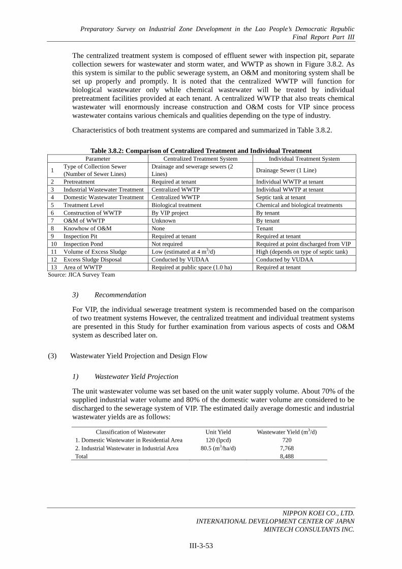
Preparatory Survey on Industrial Zone Development in the Lao People’s Democratic Republic Final Report Part III
NIPPON KOEI CO., LTD.
INTERNATIONAL DEVELOPMENT CENTER OF JAPAN MINTECH CONSULTANTS INC.
III-3-53
The centralized treatment system is composed of effluent sewer with inspection pit, separate collection sewers for wastewater and storm water, and WWTP as shown in Figure 3.8.2. As this system is similar to the public sewerage system, an O&M and monitoring system shall be set up properly and promptly. It is noted that the centralized WWTP will function for biological wastewater only while chemical wastewater will be treated by individual pretreatment facilities provided at each tenant. A centralized WWTP that also treats chemical wastewater will enormously increase construction and O&M costs for VIP since process wastewater contains various chemicals and qualities depending on the type of industry.
Characteristics of both treatment systems are compared and summarized in Table 3.8.2.
Table 3.8.2: Comparison of Centralized Treatment and Individual Treatment Parameter Centralized Treatment System Individual Treatment System
1 Type of Collection Sewer (Number of Sewer Lines)
Drainage and sewerage sewers (2 Lines) Drainage Sewer (1 Line)
2 Pretreatment Required at tenant Individual WWTP at tenant 3 Industrial Wastewater Treatment Centralized WWTP Individual WWTP at tenant 4 Domestic Wastewater Treatment Centralized WWTP Septic tank at tenant 5 Treatment Level Biological treatment Chemical and biological treatments 6 Construction of WWTP By VIP project By tenant 7 O&M of WWTP Unknown By tenant 8 Knowhow of O&M None Tenant 9 Inspection Pit Required at tenant Required at tenant 10 Inspection Pond Not required Required at point discharged from VIP11 Volume of Excess Sludge Low (estimated at 4 m3/d) High (depends on type of septic tank) 12 Excess Sludge Disposal Conducted by VUDAA Conducted by VUDAA 13 Area of WWTP Required at public space (1.0 ha) Required at tenant
Source: JICA Survey Team
3) Recommendation
For VIP, the individual sewerage treatment system is recommended based on the comparison of two treatment systems However, the centralized treatment and individual treatment systems are presented in this Study for further examination from various aspects of costs and O&M system as described later on.
(3) Wastewater Yield Projection and Design Flow
1) Wastewater Yield Projection
The unit wastewater volume was set based on the unit water supply volume. About 70% of the supplied industrial water volume and 80% of the domestic water volume are considered to be discharged to the sewerage system of VIP. The estimated daily average domestic and industrial wastewater yields are as follows:
Classification of Wastewater Unit Yield Wastewater Yield (m3/d) 1. Domestic Wastewater in Residential Area 120 (lpcd) 720 2. Industrial Wastewater in Industrial Area 80.5 (m3/ha/d) 7,768 Total 8,488

Preparatory Survey on Industrial Zone Development in the Lao People’s Democratic Republic Final Report Part III
NIPPON KOEI CO., LTD.
INTERNATIONAL DEVELOPMENT CENTER OF JAPAN MINTECH CONSULTANTS INC.
III-3-54
2) Groundwater Infiltration
Groundwater infiltration and unexpected surface water intrusion shall be considered when designing the capacity of the sewerage collection system. Groundwater infiltration including unexpected surface water intrusion is assumed to be 5% to 10% of daily average wastewater flow (DAWF). In this study, the proposed rate is 10% of DAWF, considering the geological conditions in VIP.
3) Design Wastewater Flow
In this study, three types of wastewater volumes are used for designing various sewerage facilities:
- Daily Average Wastewater flow (DAWF): Generally applied in designing sludge treatment process and basic data for tariff collections
- Daily Maximum Wastewater flow (DMWF): Generally applied in designing wastewater treatment process, which can retain the maximum inflow throughout a year
- Hourly Maximum Wastewater flow (HMWF): Generally applied in designing sewer pipes and pumping station, which can handle peak flow rates due to hourly fluctuation of wastewater inflow
The ratio of each factor (peak factor) was adopted by comparing existing cases from big cities in Asian countries and general practices. The ratios were set as follows:
DAWF : DMWF : HMWF = 1.0 : 1.15 : 1.44
However, as for groundwater infiltration, the volume calculated by DAWF was also applied to DMWF and HMWF. A summary of the Design Wastewater Yield is shown in Table 3.8.3.
Table 3.8.3: Design Wastewater Flow Type of Design Flow Volume (m3/d)
Daily Ave. Wastewater Flow: DAWF 8,490 Daily Max. Wastewater Flow: DMWF 9,740 Hourly Max. Wastewater Flow: HMWF 12,340
Source: JICA Survey Team
(4) Planned Wastewater Quality
1) Unit Pollutant Load and Wastewater Quality
The wastewater discharged from polluters, such as houses and industries, always fluctuates in quality and quantity. In Vientiane Capital, not enough biochemical data of wastewater components discharged from polluters is available. As a result, it is difficult to analyze and conclude the acceptable BOD specific to VIP. Considering this, the planned wastewater quality is determined based on the results of previous studies in Japan and other Asian countries.
Table 3.8.4 presents the pollutant load per capita in hot and temperate countries in Asia. In addition, Japanese data was also analyzed for estimation purposes.

Preparatory Survey on Industrial Zone Development in the Lao People’s Democratic Republic Final Report Part III
NIPPON KOEI CO., LTD.
INTERNATIONAL DEVELOPMENT CENTER OF JAPAN MINTECH CONSULTANTS INC.
III-3-55
Table 3.8.4: Pollutant Load Per Capita in Hot/Temperate Countries BOD SS
Name of Area (Unit: gpcd) (Unit: gpcd)
Indonesia: Jakarta 30 - India 30 – 45 67 S.E. Asia 43 - JAPAN 50 – 60 40 Developing Countries (WHO) 40 - Vietnam: Hanoi 40 – 100 - (Data from Previous Study Reports)
Source: Technical Guideline for Urban Drainage and Wastewater Disposal in Developing Countries, 1993 by IDI in Japan
The planned wastewater quality for VIP is determined as follows:
- Domestic wastewater: 40 gram per capita per day (gpcd) of BOD considering Table 3.8.4.
- Industrial wastewater: 200 mg/L of BOD based on the analyzed data of industrial wastewater in Japan.
2) Design Wastewater Quality
The design wastewater quality is estimated by applying unit pollutant loads to specific wastewater flow at DAWF condition. The total amount of wastewater and pollutant load in VIP is shown in Table 3.8.5.
Table 3.8.5: Summary of Design Wastewater Quality Description Value
1. Daily Ave. Wastewater Flow: DAWF (m3/d) 8,490 a) Domestic Wastewater 720 b) Industrial Wastewater 7,770 2.Unit Pollutant Load a) Domestic (gpcd) 40 b) Industrial (mg/L of BOD) 200 3. Future Pollutant Load (kg/d) 1,792 a) Domestic 240 b) Industrial 1,552 4. Specific Unit a) Specific Yield (m3/d/ha) 61 b) Specific Load (kg/d/ha) 13 5. Influent Wastewater Quality a) BOD (mg/L) 211 b) SS (mg/L) 264 6. Proposed Removal Ratio of Treatment (%) 90 7. Efficiency of Removal (%) a) BOD 86 b) SS 85 8. Treated Wastewater Quality a) BOD (mg/L) 30 b) SS (mg/L) 40 9. Excess Sludge (m3/d) 5.0
Source: JICA Survey Team
By comparing the characteristics of sewerage with that in Japan, the average values of influent wastewater quality with 211 mg/L of BOD and 264 mg/L of SS, as mentioned above, have been considered reasonable for further planning and design purposes.

Preparatory Survey on Industrial Zone Development in the Lao People’s Democratic Republic Final Report Part III
NIPPON KOEI CO., LTD.
INTERNATIONAL DEVELOPMENT CENTER OF JAPAN MINTECH CONSULTANTS INC.
III-3-56
3) Proposed Influent and Effluent Wastewater Qualities
The influent and effluent wastewater qualities are proposed to be 211 mg/L and 30 mg/L at BOD level, respectively, as shown in Table 3.8.5. These were proposed to minimize the environmental impact on water bodies in VIP and meet the environmental quality and effluent standards in the Lao PDR.
3.8.2 Sewerage Plan
(1) Design Policy and Standards
The proposed design policy and standards for sewerage system within the area are as follows:
1) To apply the following regulations and standards:
• Standard for Discharge of Domestic Sewage and Process Wastewater from the Processing Industry Tenants, MoIC, 2006
• Standard for Wastewater Treatment from Public Areas to Environment, STEA, 1998 • National Strategy on Urban Sewerage Management and Investment Plan to the Year
2020, MPWT, 2009 • Draft Agreement of National Standards of Environment in the Lao PDR, March
2009 • Ministerial Decree on The Management of Building Construction, Department of
Housing and Urban Planning, Ministerial Decree, MPWT, 2005 • Japan Sewerage Works Association Standards, 1984 • Guideline of Industrial Wastewater Treatment Method in Japan • Domestic Wastewater Standard - JIS A3302, Japan, April 1988
2) To harmonize with the existing infrastructure, such as 450 Year Road and District Road No. 108.
3) To adopt a separate system with inspection pit and sewer for collecting treated wastewater.
4) For an individual sewerage system, to introduce a combined type septic tank (so called Gappei Johkaso in Japan) for domestic wastewater treatment and for MoIC to oblige the tenants to install the combined type septic tank, as stipulated in their respective contracts.
5) To propose the effluent standard and establish the monitoring system for treated wastewater quality in VIP.
6) To take adequate measures in line with the local conditions so as to protect the landscape, water, and living environment.
(2) Design Criteria
1) Sewerage Collection System
Separated sewer systems for all areas in the VIP shall be applied. In principle, the wastewater produced by industries will be treated prior to discharging into sewerage systems in order to meet the wastewater criteria in VIP. Highly loaded gray water and toxic/hazardous materials will be pretreated individually at the source.
Basically, VIP will be installed with gravity flow sewer system. However, pressure pipelines will also be used when the depth of the installed gravity pipe goes deeper than around 7 m or

Preparatory Survey on Industrial Zone Development in the Lao People’s Democratic Republic Final Report Part III
NIPPON KOEI CO., LTD.
INTERNATIONAL DEVELOPMENT CENTER OF JAPAN MINTECH CONSULTANTS INC.
III-3-57
when pipes must cross rivers/channels to avoid difficult and dangerous construction work, as well as escalating construction cost.
2) Materials of Sewer Pipes and Dimensions
Reinforced Concrete (RC) pipe is to be used for gravity sewer lines and Ductile Cast Iron Pipe (DCIP) is to be adopted for pressure lines. The minimum dimensions of these pipes are set at 200 mm for RC pipe and 250 mm for DCIP.
3) Hydraulic Calculation of Sewer Pipes
For designing the gravity sewerage network, Manning’s formula was applied to decide the proper dimensions for accepting the design flow rate from the area. This formula is given below:
Q = A・V V = (1/n)・R2/3・I1/2 Where, Q: Wastewater discharge (m3/s) A: Sectional area of pipe (m2) V: Mean velocity (m/s) n : Roughness coefficient R: Hydraulic radius (m) I : Hydraulic gradient
The following relrated criteria were applied to the hydraulic design of sewers:
- Roughness Coefficient (n): 0.013
- Allowable flow velocity (V): 0.6-3.0 m/s
- Hydraulic gradient (I): Considered the same as the gradient of sewer pipe (in full capacity condition)
- Allowance of sewer capacity: 100% of design HMWF
4) Minimum Earth Cover
In this study, the minimum earth cover is set at 1.50 m to allow access to discharge pipes from industries and buildings. However, the minimum earth cover for pressure pipes, which will be buried in the sidewalk, is set at 0.6 m.
5) Typical Interval of Manholes
The typical interval of manholes is arranged at 50 m to reduce construction cost and actual work for daily maintenance.
6) Relay Pumping Station
Relay pumping stations will be established to lift wastewater from deeper gravity sewers and send them to pressure lines. Stations will use submersible pumps and will be located underground along sidewalks and in green areas so as not to restrict land use or affect the landscape of VIP.

Preparatory Survey on Industrial Zone Development in the Lao People’s Democratic Republic Final Report Part III
NIPPON KOEI CO., LTD.
INTERNATIONAL DEVELOPMENT CENTER OF JAPAN MINTECH CONSULTANTS INC.
III-3-58
(3) Plan of Centralized Sewerage Treatment System
1) Hydraulic Analysis of Collection Sewer
Collection sewer of the centralized sewerage treatment system is analyzed hydraulically and planned as shown in Figure 3.8.3.
Source: JICA Survey Team
Figure 3.8.3: Wastewater Flow Model of Centralized Treatment System
2) Centralized Wastewater Treatment Method
Considering wastewater volume and quality, the conventional activated sludge process is recommended for wastewater treatment within VIP. For the sludge treatment process, a gravity thickener and mechanical dewatering process are recommended. An outline of the treatment process is shown in Figure 3.8.4.
Source: JICA Survey Team
Figure 3.8.4: Diagram of Conventional Activated Sludge Process

Preparatory Survey on Industrial Zone Development in the Lao People’s Democratic Republic Final Report Part III
NIPPON KOEI CO., LTD.
INTERNATIONAL DEVELOPMENT CENTER OF JAPAN MINTECH CONSULTANTS INC.
III-3-59
3) Overall Plan of Centralized Sewerage Treatment System
Based on the results of hydraulic analysis, an overall plan of the centralized sewerage treatment system is presented in Figure 3.8.5. One relay pumping station will be located at the industrial park center as shown in Figure 3.8.5.
Source: JICA Survey Team
Figure 3.8.5: Overall Plan of Centralized Sewerage Treatment System
The centralized sewerage treatment plan will consist of the following: i) wastewater collection sewer for industrial area, ii) wastewater collection sewer for residential area, and iii) WWTP. Table 3.8.6 presents the components of planned facilities for the centralized sewerage treatment system.
Table 3.8.6: Components of Planned Facilities for Centralized Sewerage Treatment Plan Work Item Quantity
1 Wastewater Collection Sewer for Industrial Area a) Sewer 9,061 m D200 mm RC Pipe, Shallower than 4.0 m 1,852 m D250 mm RC Pipe, Deeper than 4.0 m 2,633 m D300 mm RC Pipe, Deeper than 4.0 m 2,484 m D350 mm RC Pipe, Deeper than 4.0 m 1,772 m D500 mm RC Pipe, Shallower than 4.0 m 147 m D500 mm RC Pipe, Deeper than 4.0 m 173 m

Preparatory Survey on Industrial Zone Development in the Lao People’s Democratic Republic Final Report Part III
NIPPON KOEI CO., LTD.
INTERNATIONAL DEVELOPMENT CENTER OF JAPAN MINTECH CONSULTANTS INC.
III-3-60
Work Item Quantity b) Manhole 366 units Manhole for D200-600, 1.2 m x 1.2 m, H=4 m 224 units Manhole for D200-600, 1.2 m x 1.2 m, H=7 m 141 units
c) Relay Pumping Station
Pumping Station (H=23 m x D250 mm x 22 kW Submersible Pump: 3 units)
1 units
D250 mm Ductile Cast Iron Pipe 3,126 m 2 Wastewater Collection Sewer for Residential Area a) Sewer 1,990 m D200 mm RC Pipe, Shallower than 4.0 m 1,796 m D300 mm RC Pipe, Shallower than 4.0 m 52 m D350 mm RC Pipe, Shallower than 4.0 m 90 m D400 mm RC Pipe, Deeper than 4.0 m 52 m
b) Manhole 40 Manhole for D200-600, 1.2 m x 1.2 m, H=4 m 39 units Manhole for D200-600, 1.2 m x 1.2 m, H=7 m 1 units
3 Wastewater Treatment Plant
a) Wastewater Treatment Plant (Qmax=10,000 m3/d) Conventional Activated Process, Mechanical Sludge Process
1 units
b) Laboratory Equipments & Sampler 1 set Source: JICA Survey Team
(4) Plan of Individual Sewerage Treatment System
1) Industrial Wastewater Treatment Method
Table 3.8.7 presents the industrial wastewater characteristics and typical treatment methods categorized by type of industry. There are multifarious industrial wastewater treatment methods to be adopted not only for the individual sewerage treatment system but also for pretreatment of the centralized sewerage treatment system as shown in Table 3.8.7.

Preparatory Survey on Industrial Zone Development in the Lao People’s Democratic Republic Final Report Part III
NIPPON KOEI CO., LTD.
INTERNATIONAL DEVELOPMENT CENTER OF JAPAN MINTECH CONSULTANTS INC.
III-3-61
Table 3.8.7: Wastewater Characteristics and Treatment Methods Categorized by Industry
2) Combined Type Septic tank
In case of the individual sewerage system, the combined type septic tank is recommended for domestic wastewater treatment at industrial and residential area as shown in Figure 3.8.6. The combined type septic tank is being produced and used in Thailand. The ready-made septic tank accommodates treatment capacity of 0.5 to 100 m3/day by combining many tanks.
Industry BOD PPM COD PPM SS PPM PH Typical Treatment
1. Food Processing 1,000 - 2,700 430 - 2,700 450 - 800 1 - 14 A.S Dairy Products 250 170 200 65 - 11 A.S Seasoning 340 - 2,300 109 - 11,900 76 - 4,250 6 - 8 A.S Milling 1,900 1,600 2,400 6 - 8 OF + A.S Soft Drink 340 330 370 9 - 12 A.S Alcoholic Drink 490 -1,700 127 - 1,400 88 - 776 8 - 11 A.S Frozen 410 170 200 - A.S Confectionery 860 780 610 6 - 8 OF + A.S Feed/Fertilizer 1,200 480 25 - A.S Cooking Oil 4,400 3,100 2,600 1 - 7 OF + A.S Others 450 - 2,400 450 - 1,200 450 - 1,200 6 - 8 A.S
2. Spinning 20 - 300 30 - 610 15 - 630 3, 5 - 9 A.S Tex tile 60 30 100 6 - 8 A.S Garment 10 10 30 6 - 8 A.S Dyeing 200 - 300 160 - 450 80 - 200 3 - 11 C.D
3. Chemical Organic Chemical 300 - 600 460 - 870 100 - 150 1 - 13 N.T + A.S/C.S Plastic/Rubber 10 20 50 - N.T + A.S Petro - Chemical 20 - 200 20 - 200 20 - 100 1 - 13 OF + A.S / G.S Others 500 500 30 - A.S / C.D
4. Wood/Furniture 10 10 30 - 40 - A.S 5. Glass/Ceramic 3 - 10 1 - 13 30 - 20,000 7 - 9 C.S / F.M 6. Cement/Concrete 8 - 30 7 - 17 200 - 1,400 9 - 14 N.T 7. Metal product 20 - 360 20 - 360 20 - 560 2 - 8 N.T / C.S 8. Plate - 30 - 150 1 - 6 N.T / C.D 9. Pulp/Paper 300 250 180 7 - 9 A.S / C.S
10. Machinery 10 30 100 - OF + A.S / C.D11. Automobile 50 90 100 - OF + A.S / C.D12. Electronics 10 30 100 - OF + A.S / C.D13. Miscellaneous 5 10 40 6 - 8 A.S Source: Gridline of Industrial Wastewater Treatment Method in Japan A.S : Activated Sludge Method F.M : Filter MethodC.S : Coagulated Sedimentation N.T : Neutralization TreatO.F : Oil Floating C.D : Chemical Treat

Preparatory Survey on Industrial Zone Development in the Lao People’s Democratic Republic Final Report Part III
NIPPON KOEI CO., LTD.
INTERNATIONAL DEVELOPMENT CENTER OF JAPAN MINTECH CONSULTANTS INC.
III-3-62
(Not to Scale)
Source: JICA Survey Team
Figure 3.8.6: Typical Combined Type Septic Tank (Johkaso)
The combined type septic tank with a capacity of over 100 m3/day will be designed with a cast-in-place RC tank instead of the ready-made tank since installation cost of the latter is higher than the construction cost of the former. For domestic wastewater treatment of residential area, the communal combined type septic tank with cast-in-place RC is planned as shown in Table 3.8.8.
Table 3.8.8: Communal Combined Type Septic Tank for Residential Area Item Description
1 Capacity of Septic Tank 950 m3/d (estimated)
2 Raw Wastewater Quality BOD: 300 mg/L
3 Treatment Method Extended Aeration Process
4 Treated Wastewater Quality BOD: less than 30 mg/L
5 Structure Cast-in-place Concrete
6 Area of Septic Tank Requires about 0.2 ha Source: JICA Survey Team
3) Required Facilities for Individual Sewerage System
The individual sewerage treatment plan consists of the following: i) wastewater collection sewer for industrial area, ii) wastewater collection sewer for residential area, and iii) water quality test equipment as shown in Table 3.8.9. Industries shall provide industrial wastewater treatment plants while residents shall install their own combined type septic tank for domestic wastewater treatment.

Preparatory Survey on Industrial Zone Development in the Lao People’s Democratic Republic Final Report Part III
NIPPON KOEI CO., LTD.
INTERNATIONAL DEVELOPMENT CENTER OF JAPAN MINTECH CONSULTANTS INC.
III-3-63
Table 3.8.9: Components of Individual Sewerage Treatment Plan Work Item Quantity
1 Wastewater Collection Sewer for Industrial Area a) Outlet RC Pipe D300 278 m b) Inspection & Water Sampling Pit, 1.2 x 1.2 m, H=4 m 185 units 2 Wastewater Collection Sewer for Residential Area a) Outlet RC Pipe D300 32 m b) Inspection & Water Sampling Pit, 1.2 x 1.2 m, H=4 m 21 units 3 Water Quality Test Equipment & Sampler 1 set
Source: JICA Survey Team
(5) Recommended Effluent Standard of Wastewater
In order to apply both centralized and individual sewerage and treatment systems, effluent standard of treated wastewater for VIP is proposed as shown in Table 3.8.10.
Table 3.8.10: Effluent Standard of Wastewater for VIP
Parameter Unit Value (not higher than)BOD5 mg/l 30Ammonia Nitrogen mg/l 4Total Suspended Solid (TSS) mg/l 40pH mg/l 6-9.5Temperature* Degree Celsius 40Total dissolved solid (TDS)* mg/l 1,500COD* mg/l 120Total Kjeldahl Nitrogen ( TKN )* mg/l 100Phenols mg/l 0.3Phosphorus mg/l 1Silver mg/l 0.1Zinc mg/l 1Sulphide mg/l 1Free chlorine mg/l 1Chloride mg/l 500Iron mg/l 2Fluoride mg/l 15Cyanide mg/l 0.1Copper mg/l 0.5Lead mg/l 0.2Oil and grease mg/l 5Nickel mg/l 0.2Mercury mg/l 0.005Manganese mg/l 1Arsenic mg/l 0.25Barium mg/l 1Cadmium mg/l 0.03Chromium (+6) mg/l 0.1Total Chromium mg/l 0.5Source: Effluent Standard of MOIC, * Standard For Wastewater Treatment of WREA
(6) O&M Plan
1) Centralized Sewerage Treatment System
The following institutional aspects are taken into account to reinforce the project implementation organization and establish the O&M mechanism in Vientiane Industrial Park Authority-Management Office (VIPA-MO) for the centralized sewerage treatment system in VIP. Sewerage Treatment Works is formed in addition to the Technical Section as shown in Figure 3.8.7 for concentrating on the O&M of the sewerage treatment plant. Regular patrolling

Preparatory Survey on Industrial Zone Development in the Lao People’s Democratic Republic Final Report Part III
NIPPON KOEI CO., LTD.
INTERNATIONAL DEVELOPMENT CENTER OF JAPAN MINTECH CONSULTANTS INC.
III-3-64
and sweeping of wastewater collection sewers are conducted by the technical section on a routine basis. Main activities of the Sewerage Treatment Works are:
• Operation of the sewerage treatment plant, laboratory, relay pumping station and their maintenance;
• Regular water quality analysis for proper plant operation and inspection of wastewater quality discharged from tenants;
• Seasonal maintenance and rehabilitation of sewer lines, etc.; and • Regular measurement and monitoring of water quality and flow discharge.
Figure 3.8.7: Structure of O&M Section
For O&M of all facilities related to the centralized sewerage treatment system, 10 staffs that include a process engineer, four technicians, and four workers will be required as shown in Table 3.8.11.
Table 3.8.11: Required Staff Members for O&M Position Number of Stuff
Process Engineer 1 Process Operator 1
Mechanic 1 Electrician 1
Laboratory Technicians 2 General Workers 2 Security Guards 2
Total 10 Source: JICA Study Team
O&M of the centralized sewerage treatment system is recommended to be executed independently from other infrastructure. For the centralized sewerage project, the ratio of annual O&M cost to the direct construction cost of sewer system and sewerage treatment plant is proposed to be 0.7% and 2%, respectively. Annual O&M cost of about LAK3.91 billion per year (equivalent to JPY41 million) has been estimated for the centralized sewerage treatment system. In general, in most developed countries, O&M cost for a centralized sewerage system is recovered through beneficiaries. Thus, to secure O&M cost, the sewerage levy-based system shall be established prior to implementation of the centralized sewerage system. It is
Source: JICA Survey Team
Technical & EnvironmentalDept.
Sewerage TreatmentWorks
Process Engineer (1)
Process Operator (1)
Laboratory Technicians (2) Mechanics/Electricians (2)
Coordinating Agencies VUDAA NPVC EDL
Telecom Company WREA
Technical Section
General Workers (2) & Security Guard (2)
Environmental Section

Preparatory Survey on Industrial Zone Development in the Lao People’s Democratic Republic Final Report Part III
NIPPON KOEI CO., LTD.
INTERNATIONAL DEVELOPMENT CENTER OF JAPAN MINTECH CONSULTANTS INC.
III-3-65
recommended that sewer charges by means of prorating the O&M cost to the development area should be collected from tenants.
Since operational control of the centralized sewerage treatment system requires frequent sampling and laboratory analysis, O&M equipment are procured and secured for the proper functioning of the centralized sewerage treatment system as listed in Table 3.8.12.
Table 3.8.12: O&M Equipment No Items Unit Quantity
1 Multi water qualities monitor (pH, ORP, Water Depth, Conductivity, Temperature, Turbidity) Set 1
2 Potable DO meter Unit 1 3 pH meter Unit 1 4 Electric conductivity meter Unit 1 5 COD concentration analyzer Unit 1 6 BOD analyzer Unit 1 7 MLSS/Sludge-liquid interface meter Unit 1 8 NPK analyzer Unit 1 9 Scum thickness measure Unit 1
10 Sludge thickness measure Unit 1 11 Sludge sedimentation test graduate cylinder Unit 1 12 Multi temperature control cabinet Set 1 13 Sampler L.S. 1 14 Laboratory equipment L.S. 1 15 Reagents for 6 month use L.S. 1 16 Computer & Printer Set 1 17 Miscellaneous (Vacuum filter, etc.) L.S. 1
Source: JICA Survey Team
2) Individual Sewerage Treatment System
In the individual sewerage treatment system, wastewater is treated by tenants and treated wastewater is discharged through the storm water drainage system through inspection and water sampling pit. O&M of the individual sewerage system is recommended to be executed together with the drainage system and road network. For O&M of all facilities related to road network, drainage, and sewerage, 14 staffs that include a chief engineer, a technician and 10 workers will be required as described in Section 3.6.2. Although the annual O&M cost for the drainage and sewerage systems has been estimated at about LAK294 million per year (equivalent to JPY3.1 million), a sewerage portion of annual O&M cost has been found to be LAK100,000. The O&M cost for drainage and sewerage system shall be levied from each tenant as part of management charge for the whole area of VIP.
Sampling and laboratory analysis that are conducted by tenants and VIPA-MO shall be required to monitor adequate function of individual treatment plant of each tenant. It is recommended that the seasonal sampling and analysis will be conducted by outsourcing the parameters of effluent standard for VIP as indicated in Table 3.8.10. Meanwhile, regular sampling and water quality test will be executed by VIPA-MO using potable measures for simple parameters as shown in Table 3.8.13.

Preparatory Survey on Industrial Zone Development in the Lao People’s Democratic Republic Final Report Part III
NIPPON KOEI CO., LTD.
INTERNATIONAL DEVELOPMENT CENTER OF JAPAN MINTECH CONSULTANTS INC.
III-3-66
Table 3.8.13: Water Quality Test Equipment Item Number
a) Multi water qualities monitor (pH, ORP, Water Depth, Conductivity, Temperature, Turbidity) 1 set
b) Potable DO meter 1 set c) Sampler 1 set
Source: JICA Survey Team
(7) Conclusion and Recommendations
1) Conclusion
Table 3.8.4 presents the results of the comparison between the centralized sewerage treatment system and the individual sewerage treatment system from the aspects of required facilities, construction cost, and O&M expenses. Compared with the costs of the individual system, a huge amount of initial cost and O&M expenses are required for adopting the centralized system.
Table 3.8.14: Construction Cost and O&M Expenses of Centralized and Individual Systems Parameter Centralized Treatment System Individual Treatment System
1) Summary of Planned Facilities
Sewer 11.1 km 0.3 km Wastewater Treatment Plant 1 unit None 2) Construction Rough Cost Sewer JPY172 million JPY22 million Wastewater Treatment Plant JPY2.01 billion - Total JPY2.18 billion JPY22 million 3) Annual O&M Expenses Sewer LAK120 million LAK10 million Wastewater Treatment Plant LAK3.8 billion - Total LAK3.92 billion LAK10 million
Source: JICA Survey Team
For wastewater management in VIP, it is concluded that the individual sewerage treatment system should be adopted due to the following reasons:
i) It is risky to adopt the centralized sewerage treatment system with WWTP in VIP since the Lao PDR lacks sufficient experience and expertise for O&M of the public sewerage system with final WWTP.
ii) Larger construction cost and O&M expenses are necessary for the centralized sewerage treatment system. Moreover, long-term training is required for technology transfer regarding the proper execution of O&M of WWTP.
iii) It is considered that the centralized sewerage treatment system should be introduced gradually on the initiative of the Government of the Lao PDR as the public sewerage system relies heavily on the technology capacity available in an agency responsible for O&M of WWTP.
iv) In case the individual sewerage treatment system is applied in VIP, sewerage management is conducted easily and definitely by tenants. Tenants have sufficient know-how to treat their own industrial wastewater and manage treatment facilities.

Preparatory Survey on Industrial Zone Development in the Lao People’s Democratic Republic Final Report Part III
NIPPON KOEI CO., LTD.
INTERNATIONAL DEVELOPMENT CENTER OF JAPAN MINTECH CONSULTANTS INC.
III-3-67
v) Therefore, the individual sewerage treatment system is acceptable and proposed for sewerage management in VIP.
2) Recommendations
For the implementation of the proposed individual sewerage treatment plan, the following measures are recommended:
a) Structural Measures
• The combined type septic tank is recommended for domestic wastewater treatment at industrial area and residential area in VIP.
• Inspection and water sampling pits should be installed at each tenant to monitor treated wastewater quality.
b) Non-Structural Measures
• O&M of sewer facilities for the individual sewerage treatment system in VIP will be conducted by VIPA-MO.
• The monitoring system of treated wastewater quality shall be established adequately and promptly by VIPA-MO to ensure the reliability of the individual sewerage treatment system.