Embed Size (px)
Citation preview

LECTURE 7
Prepared by:-
KAMARUL AMIN BIN ABDULLAH @ ABU BAKAR
UiTM Faculty of Health SciencesMedical Imaging Department

LESSON OBJECTIVESAt the end of the session, the students should be able to: Briefly explain the purpose, construction
and principles of fluoroscopy. Briefly explain the image intensifier, the
principles and its construction. List the components in II and explain the
function of each components. Briefly explain its viewing and recording
system.
10/18/2012 2Kamarul Amin (c)

INTRODUCTION Fluoro: is dynamic radiographic
examination. Fluoroscopy is primarily domain of the
radiologist. However, the role of radiographer to
assist and routine post-fluoroscopic radiography.
Fluoroscopy was discover 1896.
10/18/2012 3Kamarul Amin (c)
10/18/2012 4Kamarul Amin (c)

10/18/2012 5Kamarul Amin (c)

10/18/2012 6Kamarul Amin (c)

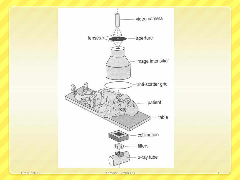
Fluoroscopic Equipment
1. X-ray Tube.
2. Image Receptor (Image Intensification).
3. Viewing Systems
4. Recording Systems
Kamarul Amin (c) 710/18/2012

Cont’d..
X-ray Tube and Image Intensification
are mounted to a C-arm to maintain their
alignment at all times.
C-arm permits the image receptor to be
raised and lower to vary the beam
geometry for maximum resolution while x-
ray tube remains in position.
10/18/2012 8Kamarul Amin (c)

Cont’d..
C-arm can move all direction.
2 types of C-arm:
under couch, and
over couch
10/18/2012 9Kamarul Amin (c)

Cont’d..
Carriage is the arm supports the equipment
suspended over the table include I.I., x-ray
tube, control power drive, spot film selection,
tube shutters, spot filming, cine camera,
video input tube etc.
Exposure cannot commence until the carriage
is return to a full beam intercept position.
10/18/2012 Kamarul Amin (c) 10

1) X-ray Tube
Similar to General X-ray Tubes except:
Designed to operate for longer periods of time at
much lower mA i.e. fluoroscopic range 0.5-5 mA
Tube target must be fixed to prevent an SOD of
less than 15 inch (~ 40 cm).
Fluoroscopic tube can operate by Foot Switch
Equipped with electrically controlled shutter.
10/18/2012 11Kamarul Amin (c)

2) Image Intensification
(II)
Was developed 1948.
Is designed to amplify the brightness of
an image.
New II are capable of increasing image
brightness 500-8000 times.
Kamarul Amin (c) 1210/18/2012

Cont’d..
Major components of an
II are:-
i. Input Window
ii. Input Phosphor
iii. Electrostatic Lenses
iv. Output Phosphor
v. Output Window
vi. Envelope
10/18/2012 Kamarul Amin (c) 13

10/18/2012 Kamarul Amin (c) 14

10/18/2012 Kamarul Amin (c) 15
10/18/2012 16Kamarul Amin (c)

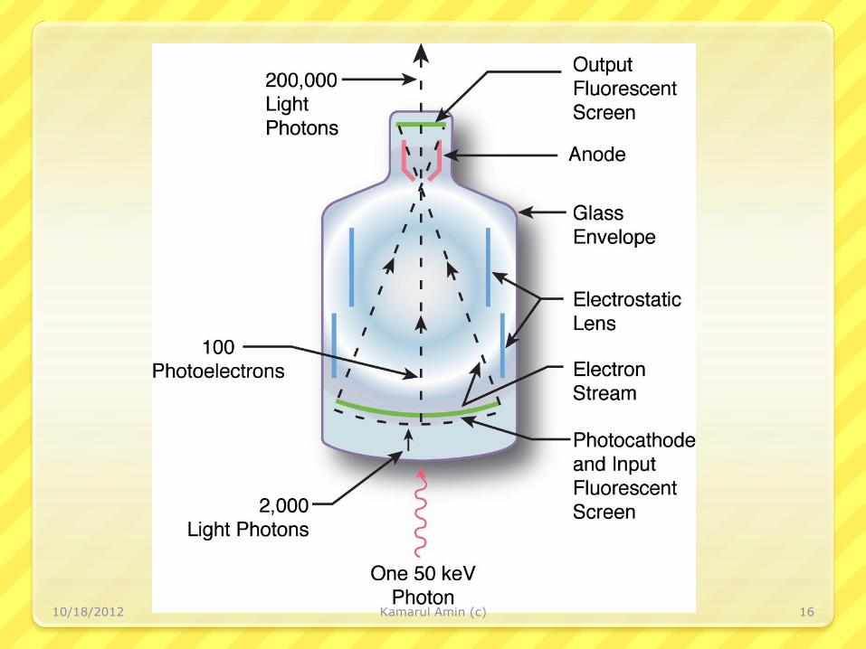
Principle Operation
The primary x-ray beam exits the patient and
strikes the input screen of the II, which is a
vacuum tube with a cathode and an anode.
Fluorescent screen is built into the image
intensifier as input screen, which absorbs the
x-ray photons and emits light photons.
10/18/2012 17Kamarul Amin (c)

Cont’d..
Photocathode is 2nd layer which prevent
divergence of the light.
The photocathode absorb the light and
emits electrons.
10/18/2012 18Kamarul Amin (c)

Cont’d..
Then electrons accelerated from the
cathode toward the anode and the output
screen by 25 kV potential difference.
Electrostatic lenses is used to accelerate
and focus the electron beam.
The output screen absorbs the electrons
and emits light photons.
10/18/2012 19Kamarul Amin (c)

Cont’d..
II is encased in a lead lined housing that
effectively absorbs the primary beam.
A getter is ion pump is used to remove
ions during operation and maintain the
vacuum within the tube.
10/18/2012 20Kamarul Amin (c)


i) Input Window
Older IIs used glass ==> x-ray scattering and absorption effects in this material.
Now use thin sheet ( 0.25 - 0.5 mm) of aluminium or titanium==> strength to sustain vacuum & minimal x-ray attenuation.
10/18/2012 Kamarul Amin (c) 22

ii) Input Phosphor Uses CsI doped with Na, deposited on aluminium
substrate. CsI:Na is grown in a structure of monocrystalline needles, each ~ 0.005 mm in diameter < 0.5 mm long. ==>Uses total internal reflexionto transmit as much light as poss'.
The aluminium substrate ~ 0.5 mm thick The input phosphor is typically 15 to 40 cm in
diameter.
10/18/2012 Kamarul Amin (c) 23

10/18/2012 Kamarul Amin (c) 24

Cont’d.. Cs and I are good absorbers of x-photons at
diagnostic energies: K-edges at 36 and 33 keV,respectively. The CsI:Na phosphor gives emittedblue visible light, directed to photocathode.
Intermediate layer (e.g. indium oxide) ==>highoptical transmission. Also chemically isolates thephosphor and photocathode.
The photocathode usually an alloy of antimonyand caesium SbCs3.
Photons interact mainly via photoelectric events==> they disappear and produce recoilelectrons.
10/18/2012 Kamarul Amin (c) 25

10/18/2012 Kamarul Amin (c) 26
CUT OFF VIEW OF II

iii) Electrostatic Lenses A vacuum enables the electrons to travel
without interacting with anything A voltage ~ 25 to 35 kV accelerates the
electrons. Electrodes are used in places (electron
optics) to guide ( focus) the electrons onto the output phosphor.
10/18/2012 Kamarul Amin (c) 27

Cont’d.. Electron current of ~10-8 to 10-7 A is
produced. Both (i) acceleration and (ii) focusing
of the electrons enables imageintensification.
10/18/2012 Kamarul Amin (c) 28

Cont’d.. The image at the output phosphor is
inverted relative to the input image at theinput phosphor (see the focal point due tothe e-optics).
Input phosphor and photocathode are intruth curved This means the electron pathlengths are equalized and reduces imagedistortion.
10/18/2012 Kamarul Amin (c) 29

iv) Output Phosphor ZnCdS: Ag is deposited on the ouput
window ~ 0.005 mm thick and 25 to 35mm in diameter.
Emits a green light upon absorption ofthe photo-electrons from thephotocathode.
10/18/2012 Kamarul Amin (c) 30

Cont’d.. A thin aluminium film on the inner surface
of the phosphor (i) electrical connection for ANODE (ii) to reflect light back towards the output window – attempts to maximize the output luminance and to prevent these light photons from `going back' into the II and interacting with the photocathode.
10/18/2012 Kamarul Amin (c) 31

10/18/2012 Kamarul Amin (c) 32

v) Output Window Various designs exist and have intention of
enhancing the 'straight thru' transmission ofphotons and preventing back reflections intothe II.
Examples are: (i) a glass window (e.g. 15mm thick) with external anti-reflection layers,(ii) tinted glass window and (ii) fibre-opticwindow
The output window image is transmitted toan optical system to be viewed by a cine-camera, photographic camera, video cameraor combinations of these.
10/18/2012 Kamarul Amin (c) 33

10/18/2012 Kamarul Amin (c) 34

vi) II Envelope II envelope is made from glass or non-
magnetic stainless steel Input window is welded to the envelope. Entire assembly is housed inside a metal
container which contains lead, forradiation shielding, and mu-metal, toshield the electron optics from externalmagnetic fields.
10/18/2012 Kamarul Amin (c) 35

Cont’d.. The input window is typically protected by
an aluminium faceplate (e.g. 0.5 mmthick) and is also a safety device in caseof implosion of the II.
Some IIs also have an anti-scatter gridmounted at the faceplate.
10/18/2012 Kamarul Amin (c) 36

Fluoroscopic Generators
Same as those used for
static/conventional radiography.
10/18/2012 37Kamarul Amin (c)

Brightness Control
Automatic Brightness Control
Automatic adjustments made to exposure factors by
equipment.
Automatic Gain Control
Amplifies video signal rather than adjusting exposure
factors.
10/18/2012 38Kamarul Amin (c)


Image Quality
Contrast
Resolution
Distortion
Quantum Mottle
Kamarul Amin (c) 4010/18/2012

Contrast Controlled by amplitude of the video signal.
It is effected by penumbral light scatter in the
input and output screens.
Affected by scatter radiation.
Back scatter effect from the output to the input
screen→ background fog.
Edge of the image decreases image contrast.
Kamarul Amin (c) 4110/18/2012

Resolution The primary limitation is 525-line raster pattern of the video
camera monitor.
Spot film or direct optical viewing depend on geometrical
factors, includes minification gain, electrostatic focal point,
input and output screen diameter, viewing system resolution
i.e. TV, OID, phosphor size and thickness.
CsI II capable of 4 lp/mm, magnification or multifield image
intensifiers capable of up to 6 lp/mm.
Kamarul Amin (c) 4210/18/2012
Distortion
Size distortion is caused the same factors affect by
static radiographic e.g. OID.
Shape distortion is caused by geometric problems.
Edge distortion problem (vignetting).
Kamarul Amin (c) 4310/18/2012

Quantum Mottle Insufficient radiation which cause grainy appearance.
Should be control by high mA and time setting.
Can be also from video noise.
Factors influence mottle are, total no. of photons
arriving retina which include radiation output, beam
attenuation, conversion efficiency, minification gain, flux
gain, total brightness gain, viewing system, distance of
the eye from the viewing system.
Kamarul Amin (c) 4410/18/2012


Viewing Systems• Older fluoroscopy equipment will have a
television system using a camera tube.
• The camera tube has a glass envelope containing a thin conductive layer coated onto the inside surface of the glass envelope.
• In a PLUMBICON tube, this material is made out of lead oxide, whereas antimony trisulphide is used in a VIDICON tube.
10/18/2012 46Kamarul Amin (c)

10/18/2012 Kamarul Amin (c) 47

10/18/2012 Kamarul Amin (c) 48
• The surface of the photoconductor isscanned with an electron beam and theamount of current flowing is related to theamount of light falling on the televisioncamera input surface.
10/18/2012 Kamarul Amin (c) 49

The scanning electron beam is producedby a heated photocathode. Electrons areemitted into the vacuum and acceleratedacross the television camera tube byapplying a voltage. The electron beam isfocussed by a set of focussing coils.
10/18/2012 Kamarul Amin (c) 50

Viewing Systems
1. Video Viewing System
2. Video Camera Tubes
A. Cathode
B. Anode
3. Video camera charge-coupled device (CCD)
4. Video monitor
5. Digital
Kamarul Amin (c) 5110/18/2012

1. Video Viewing
Systems
Closed circuit television
Video camera coupled to output screen and monitor
Video cameras
Vidicon or Plumbicon tube
CCD
10/18/2012 52Kamarul Amin (c)

2. Video Camera Tubes
Plumbicon and vidicon tubes similar
Different target materials.
Plumbicon has faster response time than vidicon.
10/18/2012 53Kamarul Amin (c)

Cont’d.. Components of Video Camera Tubes:-
1. Cathode
Control grid
2. Electromagnetic focusing coils
3. Electrostatic deflecting coils
4. Anode
Face plate
Signal plate
Target
10/18/2012 54Kamarul Amin (c)

Cont’d..
1) Cathode
Heating assembly
Electron gun
thermionic emission
Control grid
Shapes electron beam
10/18/2012 55Kamarul Amin (c)

Cont’d..
2) Electromagnetic Focusing
coils
Shape electron beam into
single point
3) Deflecting coils
Cause electron stream to
scan target in raster pattern
10/18/2012 56Kamarul Amin (c)

Cont’d..4) Anode
Face plate
Signal plate
Positively charged thin film of
graphite.
Target
Changes light pattern to
electronic signal sent to
video system.
10/18/2012 57Kamarul Amin (c)

Video Camera Charged Coupled
Devices (CCD)
Semiconducting device.
Emits electrons in proportion to amount of light
striking photoelectric cathode.
Fast discharge eliminates lag.
Kamarul Amin (c) 5810/18/2012

3. Video Camera Charged
Coupled Devices (CCD)
Operate at lower voltages than video tubes.
More durable than video tubes.
Kamarul Amin (c) 5910/18/2012

4. Video Monitor
Kamarul Amin (c) 6010/18/2012

5. Digital Fluoroscopy
Image intensifier output screen coupled to TFTs.
TFT photodiodes are connected to each pixel
element.
Resolution limited in favor of radiation exposure
concerns.
Kamarul Amin (c) 6110/18/2012


Recording the Fluoroscopic
Image
1. Dynamic Systems
Cine Film Systems
Videotape Recording
2. Static Spot Filming Systems
Cassettes
105 mm Chip Film
3. Digital Fluoroscopy
Kamarul Amin (c) 6310/18/2012

Dynamic Systems
1. Cine Film System
2. Videotape Recording
Kamarul Amin (c) 6410/18/2012
1. Cine Film Systems Consist of cine camera positioned behind output screen.
Required 90% of image intensity for proper exposure.
16 mm and 35 mm formats are currently use.
More pt dose.
Record series of static image at high speed.
Shutter and pulses of radiation should synchronize for the
exposure.
Generator and fluoro x-ray tube must able to handle large heat
loads.
Kamarul Amin (c) 6510/18/2012

2. Videotape Recording
VHS-S system required.
High resolution camera.
Recorders tape and monitors.
Operate same as home video systems.
Kamarul Amin (c) 6610/18/2012

Static Spot Filming
Systems
1. Cassettes
2. 105 mm Chip Film
Kamarul Amin (c) 6710/18/2012
1. Cassettes
Standard size - 9” x 9”.
Stored in lead-lined compartment until ready for
exposure.
When exposure is made, mA is raised to
radiographic level.
Multiple image formats.
Kamarul Amin (c) 6810/18/2012

2. 105 mm Chip Film
12 frames per second.
Beam splitting mirror.
Kamarul Amin (c) 6910/18/2012

Digital Fluoroscopy
Use CCD to generate electronic signal.
Signal is sent to ADC.
Allows for post processing and electronic storage
and distribution.
Kamarul Amin (c) 7010/18/2012