Embed Size (px)
Citation preview
Effects of secondary containment onsource term modelling
Prepared by WS Atkins Consultants Ltd
for the Health and Safety Executive
CONTRACT RESEARCH REPORT
324/2001

Effects of secondary containment onsource term modelling
S O Clark, D M Deaves, I G Lines and L C HensonWS Atkins Consultants Ltd
Woodcote GroveEpsomSurrey
KT18 5BW
The immediate risk to the surrounding population from an installation storing hazardous materials oftendepends upon the dispersion of vapour from a range of potential release events. The hazard rangesand areas covered by the dispersing releases will depend in turn on the nature of the release, and onthe particular features of the source.
Although the provision of secondary containment is designed to mitigate the impact of any release, theeffect on hazard ranges and risks is not always well understood. This report reviews the types ofsecondary containment available within the chemical industry, the extent of their use and the guidanceand Codes of Practice currently applied. It also addresses the issues of risk mitigation, including areview and discussion of methods of calculating the advantageous effects of secondary containment,and aims to provide a better understanding of the effects of such containment on the risk from aninstallation.
This report and the work it describes were funded by the Health and Safety Executive (HSE). Itscontents, including any opinions and/or conclusions expressed, are those of the authors alone and donot necessarily reflect HSE policy.

ii
© Crown copyright 2001Applications for reproduction should be made in writing to:Copyright Unit, Her Majesty’s Stationery Office,St Clements House, 2-16 Colegate, Norwich NR3 1BQ
First published 2001
ISBN 0 7176 1955 9
All rights reserved. No part of this publication may bereproduced, stored in a retrieval system, or transmittedin any form or by any means (electronic, mechanical,photocopying, recording or otherwise) without the priorwritten permission of the copyright owner.
WSA AM5225-R1/Issue 3 iii August 2000
CONTENTS
Page
1 INTRODUCTION ........................................................................................................................1 1.1 Background.........................................................................................................................1 1.2 Objectives ...........................................................................................................................1 1.3 Scope of work.....................................................................................................................1 1.4 Report outline .....................................................................................................................3
2 REVIEW OF RECENT STUDIES ...............................................................................................4 2.1 Relevant reports and their scope.........................................................................................4 2.2 CIRIA report 164................................................................................................................4
2.2.1 Pollution control ....................................................................................................4 2.2.2 Legislation and guidance.......................................................................................4 2.2.3 Current practice .....................................................................................................5 2.2.4 Relevant containment issues..................................................................................6 2.2.5 Types of containment ............................................................................................6 2.2.6 Developments and trends.......................................................................................7
2.3 SRD Reports .......................................................................................................................7 2.3.1 Scope .....................................................................................................................7 2.3.2 Bund efficiency .....................................................................................................7 2.3.3 Codes of practice ...................................................................................................8 2.3.4 Incident data ..........................................................................................................8 2.3.5 Conclusions and recommendations .......................................................................8
2.4 CCPS Guidelines ................................................................................................................9 2.4.1 Background............................................................................................................9 2.4.2 Guidelines for vapour release mitigation...............................................................9 2.4.3 Guidelines for post-release mitigation technology in the chemical process
industry................................................................................................................10
3 TYPES OF SECONDARY CONTAINMENT...........................................................................11 3.1 Categorisation...................................................................................................................11 3.2 Bunds................................................................................................................................11
3.2.1 Bund design .........................................................................................................11 3.2.2 Marine booms ......................................................................................................13 3.2.3 Mobile/temporary spill containment devices.......................................................14
3.3 Additional Skins ...............................................................................................................14 3.3.1 Vessels.................................................................................................................14 3.3.2 Pipework..............................................................................................................14 3.3.3 Double skinned process equipment .....................................................................15 3.3.4 Flange guards.......................................................................................................15
3.4 Buildings...........................................................................................................................15 3.4.1 Containment ........................................................................................................15 3.4.2 Neutralisation of contained vapours ....................................................................16
3.5 Emergency Relief via Interceptors ...................................................................................16 3.5.1 Background..........................................................................................................16 3.5.2 Relief valves ........................................................................................................16 3.5.3 Bursting discs ......................................................................................................17 3.5.4 Expansion tanks...................................................................................................17 3.5.5 Catchpots .............................................................................................................17 3.5.6 Scrubbers .............................................................................................................18
3.6 Barriers .............................................................................................................................19 3.6.1 Barrier action .......................................................................................................19
WSA AM5225-R1/Issue 3 iv August 2000
3.6.2 Water spray barriers.............................................................................................19 3.6.3 Water monitors ....................................................................................................19 3.6.4 Steam curtains .....................................................................................................20 3.6.5 Air curtains ..........................................................................................................20 3.6.6 Dry powder curtains ............................................................................................20
3.7 Removal of Material at Source.........................................................................................20 3.7.1 Absorbents...........................................................................................................20 3.7.2 Adsorbents...........................................................................................................21
3.8 Blankets or Covers............................................................................................................21 3.8.1 Typical action ......................................................................................................21 3.8.2 Foam....................................................................................................................22 3.8.3 Dry chemicals......................................................................................................22 3.8.4 Physical covers ....................................................................................................22
4 ASSESSMENT OF CURRENT PRACTICE .............................................................................23 4.1 Site Selection ....................................................................................................................23 4.2 Bunds................................................................................................................................24
4.2.1 Bund construction................................................................................................24 4.2.2 Drainage issues....................................................................................................24 4.2.3 Bunding of pumps ...............................................................................................24 4.2.4 Minimisation of evaporation ...............................................................................25 4.2.5 Overtopping issues ..............................................................................................25 4.2.6 Bunding of flammables .......................................................................................25 4.2.7 Bunding of toxic liquids ......................................................................................26 4.2.8 Use of kerbs.........................................................................................................26 4.2.9 Compatibility of materials ...................................................................................26
4.3 Additional Skins ...............................................................................................................26 4.4 Buildings...........................................................................................................................26
4.4.1 Vapour enclosure.................................................................................................26 4.4.2 Containment ........................................................................................................27 4.4.3 Weather sheltering...............................................................................................27
4.5 Emergency Relief .............................................................................................................27 4.6 Barriers .............................................................................................................................28 4.7 Removal of Material at Source.........................................................................................28 4.8 Other Measures Identified ................................................................................................28
4.8.1 Site design ...........................................................................................................28 4.8.2 Covers..................................................................................................................28 4.8.3 Flange guards.......................................................................................................28 4.8.4 Mobile devices.....................................................................................................29 4.8.5 Underground tanks ..............................................................................................29
5 REVIEW OF PERFORMANCE ................................................................................................30 5.1 Relevant Incidents ............................................................................................................30 5.2 Consideration of Secondary Containment Failures ..........................................................33
5.2.1 Lack of secondary containment provisions .........................................................33 5.2.2 Inadequacy of design ...........................................................................................34 5.2.3 Safety management system issues.......................................................................35
5.3 Vapour Cloud Mitigation..................................................................................................36 5.4 Fire Spread and Severity...................................................................................................37 5.5 Incidents Identified During Site Visits .............................................................................38
5.5.1 Hickson & Welch ................................................................................................38 5.5.2 Flexsys.................................................................................................................38 5.5.3 Solvay Interox .....................................................................................................39 5.5.4 Aventis CropScience UK Limited.......................................................................39
WSA AM5225-R1/Issue 3 v August 2000
5.5.5 Site 5...................................................................................................................39
6 CALCULATION METHODOLOGIES .....................................................................................40 6.1 Background.......................................................................................................................40
6.1.1 Consequence reduction........................................................................................40 6.1.2 Frequency considerations ....................................................................................40 6.1.3 Risk reduction......................................................................................................40
6.2 Bunds................................................................................................................................41 6.2.1 Evaporation rate...................................................................................................41 6.2.2 Bund effectiveness...............................................................................................42 6.2.3 Mitigation potential .............................................................................................45
6.3 Additional Skins ...............................................................................................................48 6.3.1 Consequence mitigation ......................................................................................48 6.3.2 Frequency effects.................................................................................................48 6.3.3 Potential for risk mitigation.................................................................................49
6.4 Building containment .......................................................................................................49 6.4.1 Previous studies for HSE.....................................................................................49 6.4.2 Available modelling techniques ..........................................................................50 6.4.3 Mitigation potential .............................................................................................52
6.5 Emergency Relief .............................................................................................................53 6.5.1 Consequence mitigation ......................................................................................53 6.5.2 Risk considerations..............................................................................................54
6.6 Barriers .............................................................................................................................55 6.6.1 Fences and shelterbelts ........................................................................................55 6.6.2 Spray barriers.......................................................................................................55
6.7 Removal of Material at Source.........................................................................................58 6.7.1 Absorbents...........................................................................................................58 6.7.2 Adsorbents...........................................................................................................59
6.8 Blankets or Covers............................................................................................................59 6.8.1 Effects..................................................................................................................59 6.8.2 Mitigation potential .............................................................................................59
6.9 Reduction of fire size and effects .....................................................................................60 6.9.1 Mechanisms .........................................................................................................60 6.9.2 Mitigation potential .............................................................................................60
6.10 Consideration of secondary containment failures.............................................................61 6.10.1 Types of failure....................................................................................................61 6.10.2 Passive equipment integrity failure .....................................................................62 6.10.3 Active equipment unavailability..........................................................................62
7 CONCLUSIONS.........................................................................................................................63 7.1 Current use of secondary containment .............................................................................63 7.2 Scope for risk reduction....................................................................................................63 7.3 Potential for improvement of risk assessment methodologies..........................................64 7.4 General recommendations ................................................................................................65 7.5 Recommendations for further work..................................................................................65
8 REFERENCES ...........................................................................................................................67
WSA AM5225-R1/Issue 3 vi August 2000
APPENDICES
APPENDIX A NOMENCLATURE ......................................................................................... A-1
APPENDIX B SITE VISIT REPORTS.....................................................................................B-1
APPENDIX C INCIDENT REPORTS......................................................................................C-1
APPENDIX D CALCULATION OF POOL EVAPORATION RATES ................................. D-1
APPENDIX E BUND OVERTOPPING CORRELATIONS....................................................E-1
APPENDIX F EFFECTS OF LOW WINDSPEED ON RELEASE RATE FROM BUILDINGS: RESULTS OF APPLICATION OF GRAB-T ........................... F-1

WSA AM5225-R1/Issue 3 1 August 2000
1 INTRODUCTION
1.1 BACKGROUND
The large scale storage of hazardous materials inevitably involves potential hazard in the event of loss of containment. Such hazards affect nearby people in the short term, but may also affect the environment, possibly over a wider area, and definitely over a longer timescale. The adverse effects of any failure of the primary containment can be reduced by the provision of some type of secondary containment.
For the purposes of this study, a secondary containment system is defined as
'any item of equipment which may help to prevent the spread of an accidental release of a hazardous substance'.
This definition encompasses a wide variety of systems, the most obvious and common example being bunding. Although bunds are applied in many cases, they are by no means the only form of secondary containment.
This study was undertaken to determine the current application of various types of secondary containment, and, in particular, to assess their effectiveness and identify methodologies which could be used to calculate their contribution to risk reduction. Such methodologies could, for example, be used in the provision of a Safety Report for an installation to which the COMAH Regulations [1] apply. Indeed the guidance to the regulations refers to equipment for limiting the consequences (Para 410 mentions, inter alia, water-spray vapour screens and secondary containment systems) and to ‘mobilisable resources’ such as booms for spillage containment (Para 412).
The specific objectives and scope are outlined in the following sections.
1.2 OBJECTIVES
The overall objective of this study was to obtain an improved understanding of the prevalence and effectiveness of secondary containment measures used within Major Hazard sites. Although this would cover the storage of hazardous chemicals at nuclear sites, it does not consider the rather different nuclear secondary containment issues. In order to meet this aim, the following specific objectives were set:
a) Ascertain the extent of usage of secondary containment measures.
b) Determine which combination of:
• type of containment • type of storage • type of release • wind speed
would give significant risk mitigation.
c) Identify appropriate methodologies for the assessment of secondary containment effects for the significant combinations considered.
1.3 SCOPE OF WORK
The scope of work for this study comprises the following 5 tasks as identified in the proposal:
WSA AM5225-R1/Issue 3 2 August 2000
Task 1 - Identification of types of secondary containment
The study will commence with a review, firstly of relevant literature which may address the effects of secondary containment. In addition, it is considered desirable to obtain data from real major hazard sites. To this end, details of five real sites will be obtained to ascertain which containment methods are actually in place. It is likely that at least two such sites could be those for which WS Atkins has undertaken Safety Cases and therefore will have relevant background information. The remaining sites will be selected, in discussion with HSE, to ensure that a representative coverage of particular types of site is obtained.
The output from this part of the study will include a list of potential secondary containment devices, such as bunds, buildings, shelters, water sprays, monitors, double skinned vessels, ventilated secondary pipes etc., together with an indication of their overall incidence, and of the types of mitigation which would be associated with each type of plant.
Task 2 - Review of performance of secondary containment
Major hazard incidents covering the last 10-15 years will be reviewed. Information will be obtained from MHIDAS, from HSE internal incident reports and, where available, from companies whose sites have been considered in Task 1. These will be reviewed in relation to the effectiveness of the secondary containment in mitigating the incident.
Task 3 - Critical appraisal of advantages and disadvantages of secondary containment
The review of Task 2 will assist in determining the advantages of secondary containment from a risk point of view. It may also identify cases in which the mitigation has not performed as expected. This will be supplemented by additional review of potential problems such as bund overtopping, water spray activation failure etc. This appraisal will therefore consider the potential for risk reduction, but will also include an assessment of the engineering issues associated with installation or construction, and the procedural issues associated with maintenance and operation.
Task 4 - Assessment of potential for risk mitigation
A number of different types of installation (probably 3) will be chosen to cover the range of materials and types of storage of interest to HSE. Experience from previous studies, together with experience of using dispersion models, will then be used to determine those types of release events which, on the basis of known use of secondary containment measures, would be most likely to be affected.
Typical 'base case' risk assessments will be considered for each type of installation, and the likely reduction of risk due to the incorporation of secondary containment will be considered. Whilst it is not intended to undertake detailed calculations, some order of magnitude assessments, based where possible on previous experience of calculating these effects, will be given.
Task 5 - Consideration of methodologies for calculating effects of secondary containment
The assessments given under Task 4 will be based on simple ad-hoc modifications to the source terms to represent the relevant effects. This task will consider more appropriate methodologies in more detail. It will include the identification of models for such effects as gas build-up in buildings, bund overtopping and impinging jets. Comments will also be
WSA AM5225-R1/Issue 3 3 August 2000
provided on the potential for application of CFD, and on any existing CFD applications, which are relevant to the effects considered.
1.4 REPORT OUTLINE
The report commences with brief reviews of relevant recent documents relating to secondary containment. This is followed, in Section 3, by a more detailed review of the various types of secondary containment which could be applied to major hazard sites, together with details of Codes, Guidelines etc for their application. Current practice is assessed in Section 4, by reference to visits undertaken at 5 representative sites, and performance of the various secondary containment measures used is considered in Section 5, by reference to incident data. Calculation methodologies are discussed in Section 6, in relation to the various types of secondary containment which are available. Conclusions are then presented in Section 7, with the main emphasis on the scope for reducing risks, and also for calculating the risk reductions. Where detailed material would interrupt the flow of the text, it has been included in an appendix. For example, Appendix A contains the Nomenclature, whilst Appendix B contains reports of the site visits which were undertaken.
WSA AM5225-R1/Issue 3 4 August 2000
2 REVIEW OF RECENT STUDIES
2.1 RELEVANT REPORTS AND THEIR SCOPE
Containment systems for the prevention of water pollution have been reviewed in some detail in a recent study reported by CIRIA [2]. The primary emphasis of the report was on the retention of materials that would otherwise contaminate land or water courses, rather than on reduction of risk from major accidents. Nevertheless, there is a wealth of useful information that feeds directly into this study, and a brief overview is given in Section 2.2. The research reported in the CIRIA document was guided by a steering group, with members drawn from Environment Agency, Home Office, Department of Environment, Fire Brigades, Independent Tank Storage Association, Institute of Petroleum, and also from industry.
Previous work, specifically on bunding, was undertaken for HSE by Barnes [3] and by Wilkinson [4]. The emphasis of these studies was on mitigation of hazardous releases, and hence they are directly applicable to this study. Barnes produced a detailed review of the design of bunds, and this was followed by Wilkinson's assessment of overtopping as a result of catastrophic tank failures. A brief review of these two SRD reports is given in Section 2.3.
In the US, Guidelines have been produced by CCPS [5, 6] on pre-release and post-release mitigation measures. These guides are briefly reviewed in Section 2.4.
Note that references to sections, tables and figures etc. given in italics in the remainder of this section relate to the relevant sections etc. in the actual documents concerned.
2.2 CIRIA REPORT 164
2.2.1 Pollution control
As indicated in Section 2.1, the primary objective of the study was to consider secondary containment in relation to pollution control. It is aimed at regulatory bodies, and also includes guidance on design, and, in some cases, considerable constructional detail, including specific methods for ensuring that bund structures are sufficiently sealed that no hazardous material will be lost to the environment.
One area which is particularly prominent is the containment and management of fire-fighting water, which, whilst clearly an environmental issue, does not affect the direct risk to persons off site.
Some useful information is provided on incidents that had severe environmental consequences, and many of these involved major hazard substances. Information is also given on the materials involved in chemical incidents, and on the causes of such incidents. A useful glossary is provided, in which definitions of different types of secondary containment are given.
2.2.2 Legislation and guidance
The legislation given in Section 3 is almost entirely related to environmental issues, and is therefore not directly relevant to the present study. The exception is the reference to the CIMAH Regulations [7], the Highly Flammable Liquids and LPG Regulations [8], and the Planning (Hazardous Substances) Regulations [9]. Technical guidance is discussed in Section 4. The guidance which is most relevant to the present study is that given by HSE [7, 10, 11, 12] and the Home Office [13]:
WSA AM5225-R1/Issue 3 5 August 2000
HSE - CIMAH guidance (1984, 1992) - HS(G)50: storage of flammable liquids, up to 10,000m3 (1990) - HS(G)52: storage of flammable liquids exceeding 10,000m3 (1991) - Specialist Inspector Report 39: bunding of bulk chemical storage vessels
HO - Manual of Firemanship (1991): compartmentation of warehouses Note that HS(G)50 [10] and HS(G) 52 [11] have subsequently been superseded by HS(G)51 [14] and HS(G)176 [15] respectively.
Section 7.2 gives a discussion of the use of hazard and risk assessment in the context of regulatory and public pressure. It includes a useful list of some of the reasons for providing secondary containment:
• bunding of flammable liquids • bunding of toxic, volatile liquids to minimise vapour release • preventing exposure of site operators to toxic materials • recovery and recycling of materials to meet waste minimisation targets.
It then indicates that each of these considerations may point to a different solution, so that it is the responsibility of the designer to balance the competing (and in some cases conflicting) requirements.
2.2.3 Current practice
This is covered in various places in the report. It is covered explicitly in Section 5, where the measures considered are primarily those which prevent or mitigate contamination of local watercourses. Particular types of secondary containment that were considered and are relevant to this study are:
• Bunds • Kerbs or ramps • Tanks • Total containment • Warehouses
Examples are given of existing facilities (in Box 5.1), and current practice regarding the sizing of secondary containment is described in some detail in Section 9.2, including such rules of thumb as the '110% rule'. Section 9.3 deals with these issues in a more fundamental manner, and suggests that secondary containment should be capable of containing:
• the total volume of substance that could be released during an incident • the maximum rainfall that would be likely to accumulate in the secondary
containment either before or after an incident • fire fighting agents (water and/or foam), including cooling water
and that, where bunds are used they should have sufficient freeboard to minimise the risk of substance escaping as a result of dynamic factors such as surge and wave action. It is noted that allowance for these dynamic effects is not specifically included in most codes for bunds at chemical sites.
Current practice is also discussed implicitly in Section 6. This gives case studies describing the results of visits to 6 sites in the UK. Of these, only the first 2, Allied Colloids at Bradford
WSA AM5225-R1/Issue 3 6 August 2000
and Monsanto (Flexsys) at Wrexham were major hazard sites. Although most of the emphasis is on retention of fire water, prevention of run-off etc, some general detail is given in relation to the secondary containment provision of these sites. For example, at the Allied Colloids site, reference is made to the bunding of storage tanks and the segregation of a new warehouse, with similar comments for the Flexsys site. A visit to the Flexsys site was also undertaken as part of the present study and a visit report is included in Appendix B.
2.2.4 Relevant containment issues
The effectiveness of secondary containment depends upon an adequate design which considers all possible failure modes of the primary containment, and ensures that the probability of bund (or other containment) failure is minimised. A number of issues that need to be considered are discussed in some detail in Section 10 including, specifically:
Bund overtopping: Dynamic effects from the wave generated by a catastrophic tank failure should be considered. Some results for typical bund wall shapes are presented in Box 10.2.
Jetting: This is referred to as spigot flow, and occurs where a tank is punctured sufficiently above the level of the bund top that the resulting liquid jet hits the ground beyond the bund. Calculations are presented to demonstrate how this can be avoided.
Overflow design: A layer of flammable liquid could be burning above a layer of water. If the level continues to rise, it is possible to design an overflow system which will result in water being siphoned off from the lower part of the bunding, rather than a running pool fire spreading from the top.
A further issue that is emphasised at various points in the text is that of maintenance. This involves ensuring that seals are adequate, that overflows are not blocked, etc. In practice, although maintenance is important, its effects on the hazardous release scenarios, which are the subject of this report, are likely to be less significant than for the prevention of pollution.
2.2.5 Types of containment
Clearly, given the different scope of the CIRIA study, it is not likely to include all the types of secondary containment relevant to this study. However, it does cover the following types in greater or lesser detail:
• Bunds
• Prefabricated bunds (integral with the tank) • Enhanced primary containment (e.g. double skinned tanks) • Secondary containment tanks • Sacrificial areas (e.g. kerbed car parking areas) • Temporary containment (e.g. sandbags) • Absorbents • Adsorbents • Booms
The detail given for each of these varies considerably, with a complete section given over to bunds, and only passing reference to many of the others. The considerable reference section is usefully categorised under various headings in Appendix A1. These include:
WSA AM5225-R1/Issue 3 7 August 2000
• Bunds • Chemical stores • Flammable liquid stores • Oil storage
2.2.6 Developments and trends
Section 5.4.3 discusses the findings of a CONCAWE report which identified future trends on groundwater protection for the oil industry, although it is noted that they would apply equally to the storage and handling of any hazardous materials. Ten such trends were quoted from the CONCAWE report, and a further 5 were added by the CIRIA document.
The lists include such features as:
• wider use of secondary containment • sleeving of pipework • incorporation of leak detection • testing of tanks and pipework • improved management and operational procedures • increased use of risk assessment to determine secondary containment requirements • bunding of all relevant new plant
2.3 SRD REPORTS
2.3.1 Scope
As indicated in Section 2.1, Barnes [3] dealt only with bunds and did not consider any other form of secondary containment. The introduction includes a list of types of storage with a brief discussion of their relative risks. A section is given on the philosophy of bunding, which includes flow charts which can be used to indicate whether bunding is necessary or not. This is followed by a section on design features, the most useful parts of which are tables giving examples of bund capacities and construction details, mostly from US data sources.
2.3.2 Bund efficiency
This is clearly one of the main thrusts of the report, and is covered by one complete section and one appendix. Consideration is given in the text to:
• size of diked areas • prevention of overtopping • effectiveness of high collar bunds • integrated containment systems (including double skinned tanks) • reduction of evaporation rates • fire fighting requirements
The appendix expands upon two of these features which are particularly relevant to risk mitigation: overtopping and evaporation. Results are given for bund overtopping as a function of the height of the liquid level normalised by the bund height. This is referenced from an HSE guidance note [16] and compares experimental with theoretical results. The effects of spigot flow (jetting over the top of the bund) are also considered, and appropriate formulae given.
WSA AM5225-R1/Issue 3 8 August 2000
Discussion is also provided of the reduction of evaporation rates of volatile liquids. This is given primarily in terms of the properties of the substrate, which has implications for bund construction, rather than on any other effects, such as covering the liquid with foam.
The work on bund overtopping was progressed by Wilkinson [4]. This considered catastrophic liquid releases, and assessed the likely overflow quantities for various slopes of bund wall. The results are discussed in the CIRIA report, where they are given pictorially in Box 10.2. They are also discussed further in Section 6.2.3 of the present report.
2.3.3 Codes of practice
Appendix 1 gives a good discussion of codes of practice which were current in 1990 for the following materials:
• LPG • LNG • Ammonia • Chlorine • Hydrogen • Flammable liquids • Toxic materials • Corrosive materials • Oxygen • Other materials
The codes reviewed are those which apply to storage in general, and may or may not refer to the need for bunds, or give any specific criteria to determine whether they are needed. For example, the sections on hydrogen and oxygen make no reference to bund requirements (not surprisingly), although they do indicate rules for siting in relation to other flammable materials. The section on other materials covers such hazardous substances as bromine, hydrogen fluoride and phosgene. Most of the codes referred to from this section were internal ICI codes developed in the early 1970s.
2.3.4 Incident data
An appendix is devoted to a consideration of incidents involving releases from storage of hazardous materials. These were drawn from a number of reviews, some of UK data and some of US data, but most of which were undertaken in the late 1970s. A few incidents are described in which bunding was clearly inadequate. However, in most of the incidents referenced, no information could be gleaned regarding the performance of the secondary containment. Some statistics are presented from a 1978 US study [17], and these give an indication of the causes of failures and the areas in which they occurred.
2.3.5 Conclusions and recommendations
Most of the conclusions related to the status of current codes of practice, their diversity and, in some cases, their inconsistency. It seems that each has been developed on an ad hoc basis for a particular application with no consideration of other applications. One of the recommendations therefore suggested that a specific code of practice on bunding should be produced to replace the present ad hoc arrangements.
WSA AM5225-R1/Issue 3 9 August 2000
It was also recommended that more information should be obtained on:
• Bund overtopping • Materials of construction • Effect of thermal shock • Cost of bunding, leading to possible cost-benefit analysis • Asymmetric dynamic loading
2.4 CCPS GUIDELINES
2.4.1 Background
Since the mid 1950s, the American Institute of Chemical Engineers has been involved with process safety and loss control issues in the chemical, petrochemical, hydrocarbon process, and related industries and facilities.
The Center for Chemical Process Safety (CCPS), a directorate of AIChE, was established in 1985 to develop and disseminate information for use in the prevention of major chemical incidents. With the support and direction of the CCPS Advisory Managing Boards, a multifaceted programme was established to address the need for process safety management systems to reduce potential exposures to the public, facilities, personnel, and the environment. This programme is ongoing, and involves, amongst other activities, the development and publication of guidelines relating to specific areas of process safety management.
In 1988, Guidelines for Vapour Release Mitigation, a survey of then current industrial practice for controlling accidental releases of hazardous vapours and preventing their escape from the source area, was published [5]. Its focus was primarily on pre-release factors, including inherently safer plants and engineering design matters. In 1997, Guidelines for Postrelease Mitigation Technology in the Chemical Process Industry was published [6]. As the title suggests, it is concerned primarily with mitigation factors which apply after a release has occurred.
2.4.2 Guidelines for vapour release mitigation
Although the focus of this guide is on pre-release factors, there is some useful material relating to the secondary containment issues, which are the subject of this report. For example, after some background discussion of types, causes and consequences of release, there is a section on mitigation approaches. These include inherent safety, engineering design, process operation and emergency action. Of these, engineering design would cover such features as bunds, and emergency action covers activation of sprays and foams.
The section on engineering design includes double containment, catch tanks, absorbers and adsorbers, as well as scrubber systems. The detailed section on containment includes:
• double walled vessels and pipes • enclosures and walls • dikes (bunds), curbs, trenches and impoundments.
Diagrams are given for typical applications, and references are provided to relevant (US) codes.
A chapter on 'mitigation through counter-measures' describes various systems for minimising the impact of a release once it has occurred. It is divided into sections on counteracting vapour releases (via water sprays, and water, steam or air curtains) or liquid releases (via

WSA AM5225-R1/Issue 3 10 August 2000
dilution, neutralisation or covers). A particularly useful table is provided indicating which types of material can be used to cover various types of vaporising liquid spills.
2.4.3 Guidelines for post-release mitigation technology in the chemical process industry
As noted in Section 2.4.1, this guide deals with post-release factors, and is therefore extremely relevant to the subject of secondary containment. After a brief assessment of pre-release mitigation techniques, the overview covers release scenarios, consequences and broad types of post-release mitigation technique. Chapters then follow on vaporisation reduction, fluid curtains and secondary containment. In each of the sections, information is provided about the most appropriate application of each technique, including sizing, materials etc. and in some cases comments are provided on the effectiveness of various measures. For example, it is noted that a single layer of ping-pong balls floating on a liquid surface failed to reduce the vaporisation rate, whereas multiple layers did effect a reduction.
The chapter on secondary containment covers:
• diking
• double wall containment
• enclosures
• transfer vessels
• leak plugging
• physical vapour barriers
Varying levels of detail are given for each of these containment types. For example, the effects of vapour fences on downwind concentration are shown in some detail, whereas the mitigation effect is not quantified for the other cases. Standards are referenced where they are available, and discussion is provided of design, and on the use of materials.
A particularly useful chapter is provided giving examples of mitigation effectiveness. This covers consequence modelling only, rather than the full implications to a risk assessment, but provides useful calculations showing the effectiveness of the following measures:
• Bunds
• Use of Foam
• Refrigeration
• Water Sprays
Results of these calculations (for all except refrigeration) are discussed in Sections 6.2.3, 6.8.2 and 6.6.2 respectively.
WSA AM5225-R1/Issue 3 11 August 2000
3 TYPES OF SECONDARY CONTAINMENT
3.1 CATEGORISATION
This section identifies and describes all the various types of secondary containment that are commonly encountered in the process industries for dealing with potential major hazard situations, and discusses the relevant Codes of Practice or Guidelines as appropriate. The emphasis of the section is on describing the types of secondary containment in use, indicating likely application etc. Section 6 covers the same types of secondary containment measure, but gives more detail on how to assess their effectiveness in relation to the reduction of the consequences of a release, and hence of the risk
Secondary containment systems can be divided into two main types:
• passive systems - which are always in place, ready to contain any release without any further actions being taken (e.g. bunds)
• active systems - which need to be activated or put in place when a release has occurred, or is about to occur (e.g. water sprays)
In some instances, a combination of these approaches is used to contain the spread of material.
The types of secondary containment identified may be broadly classified under the following headings:
• Bunds • Additional Skins • Buildings • Emergency Relief via Interceptors • Barriers • Removal of Material at Source
• Blankets or Covers
3.2 BUNDS
3.2.1 Bund design
Bunds (or Dikes) are structures or equipment that are used to contain spillages of liquid. The bunds may be either active (e.g. mobile booms) or passive (e.g. earth berms). Bunds act to restrict the spread of hazardous liquids and to reduce the maximum surface area of a pool. Bunding can also enable other mitigation techniques to be used in a more effective and efficient manner.
For a cylindrical tank surrounded by a circular bund (Figure 3.1), the following relationship exists for the height of the bund wall required to provide 100% containment (assuming that bund overtopping or spigot flow does not occur):
A ≥ ( R2 H ) / (R + L)2 (3.1)
WSA AM5225-R1/Issue 3 12 August 2000
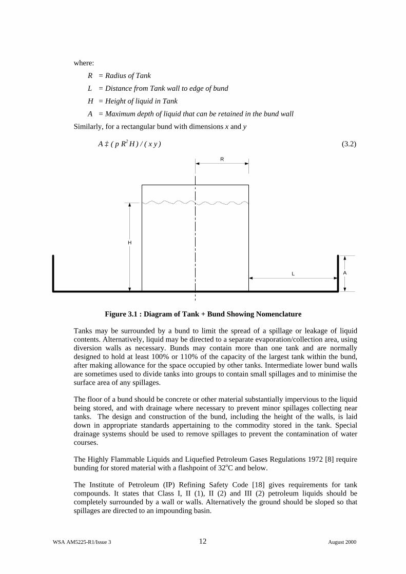
where:
R = Radius of Tank
L = Distance from Tank wall to edge of bund
H = Height of liquid in Tank
A = Maximum depth of liquid that can be retained in the bund wall
Similarly, for a rectangular bund with dimensions x and y
A ≥ ( π R2 H ) / ( x y ) (3.2)
L
H
R
A
Figure 3.1 : Diagram of Tank + Bund Showing Nomenclature
Tanks may be surrounded by a bund to limit the spread of a spillage or leakage of liquid contents. Alternatively, liquid may be directed to a separate evaporation/collection area, using diversion walls as necessary. Bunds may contain more than one tank and are normally designed to hold at least 100% or 110% of the capacity of the largest tank within the bund, after making allowance for the space occupied by other tanks. Intermediate lower bund walls are sometimes used to divide tanks into groups to contain small spillages and to minimise the surface area of any spillages.
The floor of a bund should be concrete or other material substantially impervious to the liquid being stored, and with drainage where necessary to prevent minor spillages collecting near tanks. The design and construction of the bund, including the height of the walls, is laid down in appropriate standards appertaining to the commodity stored in the tank. Special drainage systems should be used to remove spillages to prevent the contamination of water courses.
The Highly Flammable Liquids and Liquefied Petroleum Gases Regulations 1972 [8] require bunding for stored material with a flashpoint of 32oC and below.
The Institute of Petroleum (IP) Refining Safety Code [18] gives requirements for tank compounds. It states that Class I, II (1), II (2) and III (2) petroleum liquids should be completely surrounded by a wall or walls. Alternatively the ground should be sloped so that spillages are directed to an impounding basin.
WSA AM5225-R1/Issue 3 13 August 2000
Guidance on bunding for flammable liquids is also given in HS(G)176 [15]. This document supersedes previous guidance given in HS(G)50 [10] and HS(G)52 [11].
The Standard for the Production, Storage and Handling of Liquefied Natural Gas [19] suggests various alternative types of impounding area to minimise the consequences of accidental LNG releases. These impounding areas should have a volume of 100% of the largest tank within the area. Guidance is also given on the design requirements and construction materials for dikes, although no mention is made of the use of high collar bunds, which are typically specified, for LNG storage.
Guidance on LNG storage is also given by the Institution of Gas Engineers [20]. This suggests that a natural or artificial bund should be provided, and that it should be capable of holding the contents of a full tank. The bund walls should be at least 15 m high, and the distance between the tank and the top of the bund wall is defined by L ≥ 0.6(H-A) subject to L ≥ 15 m, where H is the height of liquid in the full tank and A is the height of the bund. (The factor 0.6 arises as the discharge coefficient of the release from an orifice; CIRIA [2] suggests conservatively replacing this by unity, such that L > H-A. See Section 6.2.2 of the present report). The code also specifies minimum distances between bunds and adjoining buildings, boundaries and other tanks.
A Code of Practice issued by BCGA [21] for the storage of Liquid Oxygen at production sites states that a means of controlling liquid flow should be provided, e.g. catchment ditches, barriers or slopes. However, no specific mention is made of the use of bunds around liquid oxygen storage tanks.
Similarly, the NFPA Code of Practice for Bulk Oxygen systems [22] does not suggest bunding for oxygen storage systems. However, where bulk oxygen systems are located on ground lower than adjacent storage areas for flammable or combustible materials, then dikes, curbs, etc. should be installed around the flammable storage area in order to prevent accumulation of liquids under bulk oxygen storage systems.
3.2.2 Marine booms
Secondary containment devices for containing spills that occur onto water are also available. These normally require active deployment following the onset of a spill.
Solid booms can be manufactured from stainless steel and are seawater and acid proof. These booms are manufactured in fixed lengths and a number may be fixed together to form a retention boom. However, these booms present a storage problem when not in use.
Solid booms that float due to small buoyancy floats attached at intervals along the boom are also available. The floats are made from closed cell polythene and, where they are attached the boom can be bent, thus allowing flexibility to encircle leak points. Ballasting is provided by steel weights along the bottom edge. This type of boom appears as a vertical wall for control of the spill.
Inflatable type booms may also be used to contain spills onto water. The advantage of this type of boom is that it is rolled onto a drum for transportation and quick deployment, and then after use, it can be deflated and rolled back onto the drum for disposal. These types of booms range from a few hundred millimetres in diameter to tens of feet. They may also be used as trail booms in which the boom is towed behind a vessel and the spill is gathered up.
WSA AM5225-R1/Issue 3 14 August 2000
3.2.3 Mobile/temporary spill containment devices
Mobile or temporary bunding devices may also be used on land and involve either passive or active deployment.
When filling liquid waste drums or storing liquid products, the drums can be placed on a passive drip tray type floor. When drums are stored on their side in a rack, small drip trays may also be provided to catch drips and spills.
During maintenance operations on valves, pipes or flanges etc., drip trays or containers may be used to collect residues. Absorbent materials can also be wrapped around the equipment or placed on the floor to soak up spillages.
In the case of spillages occurring where passive containment devices have not been implemented, e.g. in the case of highway incidents, the spillage can be prevented from entering surface drainage systems by the application of mobile devices. For example, drains can be covered with Neoprene mats.
Pre-packed spill kits can be obtained which contain absorbant materials, mats, pillows, mini booms, drain protectors etc. These spill kits can be placed adjacent to vulnerable areas ready for immediate action, for example in loading and off loading areas.
3.3 ADDITIONAL SKINS
For chemicals that pose severe release hazards, an effective but costly way to provide spill containment is to use double walls on the vessels, piping or other process equipment. This type of containment is primarily used for toxic materials since an additional explosion risk may be introduced by the adoption of such measures for flammable materials.
3.3.1 Vessels
Often construction materials for the outer (secondary) wall are the same as those of the primary inner wall. In case of inner-wall failure, the outer wall will have to withstand the temperature, pressure, and corrosivity of the process fluid. Lower design conditions for the outer wall may be acceptable, depending on the type of annular space monitoring provided for detecting primary failure, and the length of time for which the outer wall is expected to function without breach. Typical detection mechanisms include gas analysers or pressure detectors for vapours, conductivity switches for liquids, or “weep” holes routed to drain systems that are periodically monitored. A purge gas is sometimes used as a detection medium, such that contaminants revealed upon analysis of the purge gas exhaust will indicate a leak.
The Chemical Industry Association (UK) recommends a variation in double-containment design where only refrigerated vapours are present in the annular space between the two walls [23].
3.3.2 Pipework
Pipework may also be constructed with double walls, and the detection of leaks can be implemented in a similar way to that described above for vessels. However, some commercially supplied pipes are constructed of special metals suitable for the commodity, both for inner and outer skins, and provided with leak detection using sensor cable. Also, the outer skin may be plastic coated for weather protection and insulation.
WSA AM5225-R1/Issue 3 15 August 2000
Pipework may also be laid in tunnels incorporating a lining to prevent spillages from affecting the surroundings, and also to direct any spillages to secondary containment basins or reservoirs.
In the above circumstances, consideration must also be given to the risk of explosion in confined spaces when dealing with flammable materials.
3.3.3 Double skinned process equipment
In situations where leaks from pumps and valves may cause hazardous situations, these may also be enclosed. In such cases the enclosures should be constructed from materials that are compatible with the process fluid. For example, for use with chlorine the body must be forged steel, as cast iron is not acceptable, and pump and valve gland seals should be PTFE.
3.3.4 Flange guards
These guards are not designed and fitted to prevent leaks but are used to prevent leaks from spraying over adjacent areas and causing large areas of contamination or potentially large fire areas. They also provide protection for personnel located in adjacent areas at the time of a leak. In addition, they effectively mitigate the dispersion of fine sprays of toxic materials in non-volatile solutions, by inducing enhanced liquid rain-out at source.
The guards may be fixed to the flange edges by set screws and can be removed without interfering with the flange security. Some designs fully enclose the flange whilst others leave the flange screws exposed as an anti-corrosion measure.
3.4 BUILDINGS
3.4.1 Containment
Buildings where processes are carried out using one or more chemicals can have containment methods incorporated into their design and construction. To function properly as an enclosure, a structure should be as airtight as possible and able to be purged and vented if a release occurs. Releases from enclosures are typically either scrubbed before being released to the atmosphere, vented to a safe location, or routed to a flare system.
Buildings or enclosures can also be built around loading / unloading bays in order to mitigate any releases associated with the transfer of materials from delivery tankers to plant storage vessels. Again, in order to be effective, such buildings are required to be totally enclosed during delivery operations (tanker access door secured adequately) and to incorporate an effective venting and scrubbing system.
Where the dangerous substances are liquids, floors should be impervious and resistant to the liquid. There should also be bunds to contain the liquid, and sills to prevent its spread through doorways. In areas where the risk of spillage is high, there should be a separate drainage system with sloped floor, a bund and a collection sump.
Small fixed or portable chemical stores can also be employed as enclosures. These may be brick built, or constructed from redundant road vehicle bodies or shipping containers etc. Small hazardous or flammable stores can be obtained from specialist suppliers. These stores are supplied in modular form containing special features for given types of hazardous materials. They can be constructed to customer requirements and usually contain a raised perforated floor.
WSA AM5225-R1/Issue 3 16 August 2000
Enclosures and buildings are most effective when used in conjunction with a leak detection system. Such systems should be continuously monitored and connected to both local and control room alarms.
There are however some safety concerns related to the use of buildings as secondary containment due to the confined space thus created. One concern is the potential for a build up of asphyxiating gases if the building is improperly ventilated. In addition, for processes involving potential releases of flammable gases, the result of poor ventilation could be to concentrate the release above the lower flammability limit and the consequences of an ignition could become more onerous due to the confined nature of the subsequent explosion. Some mitigation of this enhanced explosion risk can, however, be provided by roof vents
3.4.2 Neutralisation of contained vapours
Although buildings will act as a temporary containment, they are never completely air tight, and, if the released material is a vapour, it will eventually be discharged to atmosphere. It is therefore advantageous to consider the incorporation of a vapour scrubbing system to neutralise the hazardous material before discharge to atmosphere. Scrubbing systems are described in detail in Section 3.5.6.
3.5 EMERGENCY RELIEF VIA INTERCEPTORS
3.5.1 Background
Under emergency conditions the consequences of an accidental release or dangerous process deviation may be mitigated by the controlled discharge of the hazardous inventory at a predetermined ‘safe’ location. If direct discharge to the atmosphere is not desirable then relief headers (collection systems) can be designed to retain the relief discharges.
Emergency depressurisation systems can be used to relieve pressure in a process and hence either prevent an accidental release from occurring, or reduce the inventory available for release in the case when a leak does occur. Back pressure on the relief device, and instantaneous load imposed in the relief system, both need to be considered in the design of such systems. The capacity of the relief system should be such that it can cope with initial and subsequent discharges.
Guidelines on the design of such systems are given in API-521 [24].
These depressurisation systems may incorporate a number of relief and interception devices including:
• Relief valves • Bursting discs • Expansion tanks • Catchpots • Scrubbers
3.5.2 Relief valves
Relief valves are commonly used for overpressure protection because they are self closing and can thus limit the duration of the release. An American Society of Mechanical Engineers code [25] limits the back pressure on a relief valve to 10% of the set pressure, unless the valve has a pressure-compensating bellows or similar protection against the effects of back pressure. Pilot operated relief valves may be designed to be unaffected by back pressure, but
WSA AM5225-R1/Issue 3 17 August 2000
they have other limitations (e.g. clogging of pressure sensing lines) that may prevent their use in some service environments.
3.5.3 Bursting discs
If fast action or considerable relief capacity is required, then bursting discs may be necessary. Bursting discs may also be employed in conjunction with relief valves where it is desirable to isolate the relief valve from the process environment, e.g. to prevent corrosion of the valve. In such cases, however, careful attention must be paid to the design and maintenance of the system to prevent inadvertent disabling of the relief system. If the pressure in the chamber between the bursting disc and the relief valve is allowed to increase above atmospheric pressure (e.g. due to a small leak in the disc), the effective bursting pressure of the system will increase since the bursting disc will only relieve when the differential pressure across the disc reaches the design rating. Hence, such a chamber should either be maintained at atmospheric pressure or the pressure should be monitored and alarmed.
Certain installations may warrant special consideration for the design of the bursting disc to prevent undesirable secondary effects following device activation. Some types of disc may yield fragments that could clog or damage a downstream relief valve. In such cases, either a fragmentation chamber can be incorporated into the design, or, preferably, a non-fragmenting disc could be specified.
3.5.4 Expansion tanks
For certain materials, such as chlorine, it is not desirable that pressure relief is discharged to atmosphere. In chlorine systems, pressure relief should be provided by a bursting disc, since chlorine tends to corrode relief valves. The relief should then pass to an expansion vessel, which should be sized with a capacity of at least 10% of that of the largest storage vessel. Absorbers are then generally provided to deal with any material which enters the expansion tank.
3.5.5 Catchpots
Where the vapour being discharged under emergency conditions is a two-phase, vapour-liquid mixture, the stream is often routed to a vapour-liquid separator, with a catch tank or “knock-out drum” being the most common types. These are passive devices that are used to eliminate the liquid phase from the release.
Information for the design of catchtanks is given by Grossel [26]. In the case where a catch tank or 'knock-out drum' is part of the vapour-liquid mixture separation, the design of the catchtank follows two main criteria;
• sufficient diameter to effect good vapour-liquid separation, and
• sufficient total volume to hold the estimated amount of liquid carryover.
For a foamy discharge, the holding volume should be at least 50% greater than the liquid volume in the source vessel.
It is normal practice to provide a drainage system to remove any liquids that are contained within the catchpot. This liquid should ideally be returned to the process for purification and recovery. Inerting or purging of a catchpot may need to be provided where flammable vapours are involved.
WSA AM5225-R1/Issue 3 18 August 2000
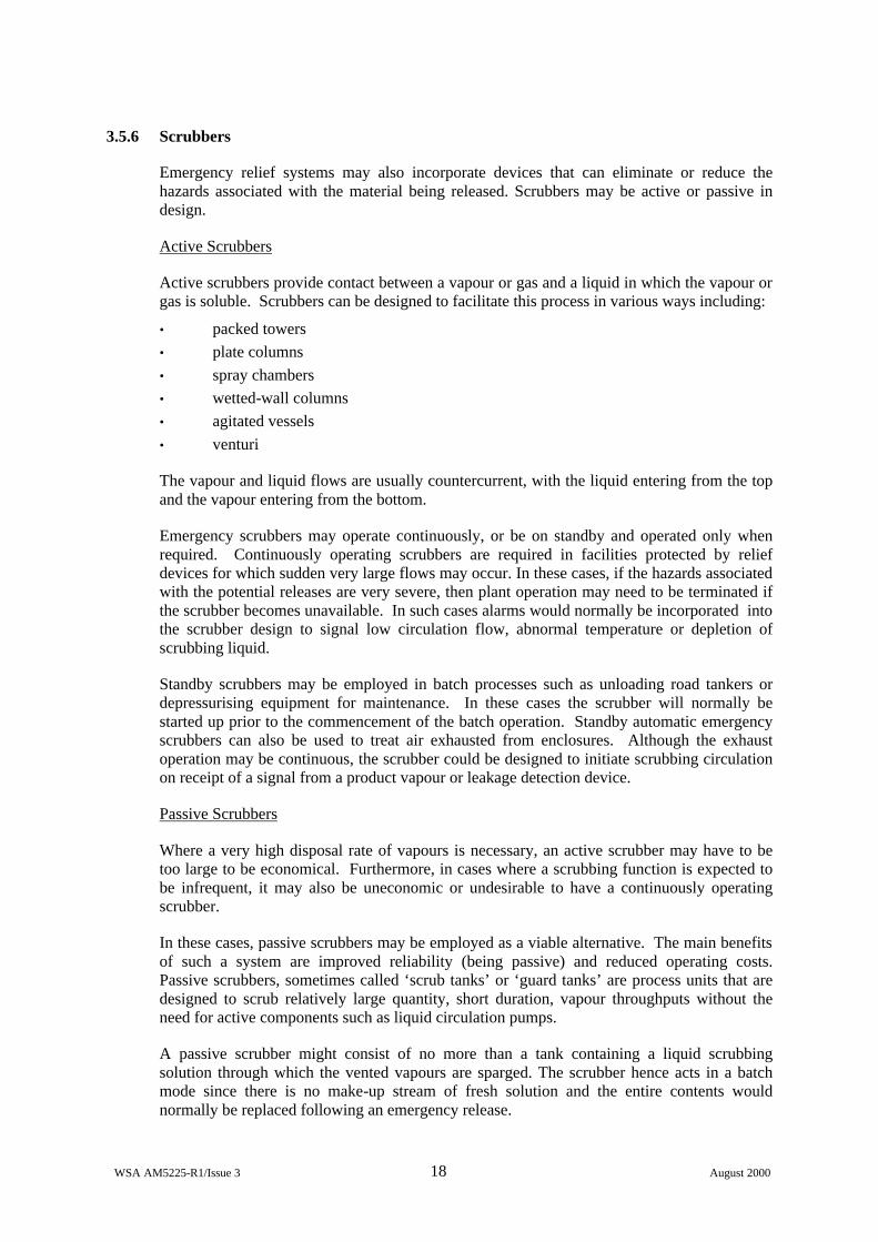
3.5.6 Scrubbers
Emergency relief systems may also incorporate devices that can eliminate or reduce the hazards associated with the material being released. Scrubbers may be active or passive in design.
Active Scrubbers
Active scrubbers provide contact between a vapour or gas and a liquid in which the vapour or gas is soluble. Scrubbers can be designed to facilitate this process in various ways including:
• packed towers • plate columns • spray chambers • wetted-wall columns • agitated vessels • venturi
The vapour and liquid flows are usually countercurrent, with the liquid entering from the top and the vapour entering from the bottom.
Emergency scrubbers may operate continuously, or be on standby and operated only when required. Continuously operating scrubbers are required in facilities protected by relief devices for which sudden very large flows may occur. In these cases, if the hazards associated with the potential releases are very severe, then plant operation may need to be terminated if the scrubber becomes unavailable. In such cases alarms would normally be incorporated into the scrubber design to signal low circulation flow, abnormal temperature or depletion of scrubbing liquid.
Standby scrubbers may be employed in batch processes such as unloading road tankers or depressurising equipment for maintenance. In these cases the scrubber will normally be started up prior to the commencement of the batch operation. Standby automatic emergency scrubbers can also be used to treat air exhausted from enclosures. Although the exhaust operation may be continuous, the scrubber could be designed to initiate scrubbing circulation on receipt of a signal from a product vapour or leakage detection device.
Passive Scrubbers
Where a very high disposal rate of vapours is necessary, an active scrubber may have to be too large to be economical. Furthermore, in cases where a scrubbing function is expected to be infrequent, it may also be uneconomic or undesirable to have a continuously operating scrubber.
In these cases, passive scrubbers may be employed as a viable alternative. The main benefits of such a system are improved reliability (being passive) and reduced operating costs. Passive scrubbers, sometimes called ‘scrub tanks’ or ‘guard tanks’ are process units that are designed to scrub relatively large quantity, short duration, vapour throughputs without the need for active components such as liquid circulation pumps.
A passive scrubber might consist of no more than a tank containing a liquid scrubbing solution through which the vented vapours are sparged. The scrubber hence acts in a batch mode since there is no make-up stream of fresh solution and the entire contents would normally be replaced following an emergency release.
WSA AM5225-R1/Issue 3 19 August 2000
There are clearly reliability and economic advantages in a passive system such as this; however, there would be no benefit from the system if the scrubber does not contain ‘potent’ liquid at the time of a release. Consequently, good administrative controls are essential to ensure that adequate liquid levels are maintained in the scrubber. In very hazardous processes, consideration could be given to an interlock that would prevent the operation of the process if the liquid in the scrubber fell below a certain level.
3.6 BARRIERS
3.6.1 Barrier action
A solid barrier such as a fence or wall can serve either to contain a gas cloud entirely or to effect an appreciable dilution. An impermeable barrier designed for this purpose and erected within the works is generally known as a vapour barrier. A barrier does not need to be impermeable to mitigate a gas release; for example, a plantation of trees may provide a worthwhile degree of dilution of a gas cloud, or even have a ‘scrubbing’ effect on certain gases [27]. However, the introduction of such barriers to limit the spread of vapour clouds may introduce vapour cloud explosion hazards when flammable gases are involved.
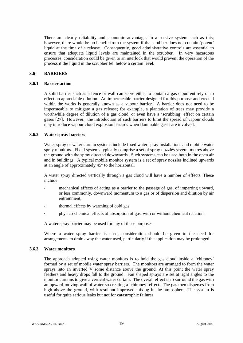
3.6.2 Water spray barriers
Water spray or water curtain systems include fixed water spray installations and mobile water spray monitors. Fixed systems typically comprise a set of spray nozzles several metres above the ground with the spray directed downwards. Such systems can be used both in the open air and in buildings. A typical mobile monitor system is a set of spray nozzles inclined upwards at an angle of approximately 45° to the horizontal.
A water spray directed vertically through a gas cloud will have a number of effects. These include:
• mechanical effects of acting as a barrier to the passage of gas, of imparting upward, or less commonly, downward momentum to a gas or of dispersion and dilution by air entrainment;
• thermal effects by warming of cold gas;
• physico-chemical effects of absorption of gas, with or without chemical reaction.
A water spray barrier may be used for any of these purposes.
Where a water spray barrier is used, consideration should be given to the need for arrangements to drain away the water used, particularly if the application may be prolonged.
3.6.3 Water monitors
The approach adopted using water monitors is to hold the gas cloud inside a ‘chimney’ formed by a set of mobile water spray barriers. The monitors are arranged to form the water sprays into an inverted V some distance above the ground. At this point the water spray feathers and heavy drops fall to the ground. Fan shaped sprays are set at right angles to the monitor curtains to give a vertical water curtain. The overall effect is to surround the gas with an upward-moving wall of water so creating a ‘chimney’ effect. The gas then disperses from high above the ground, with resultant improved mixing in the atmosphere. The system is useful for quite serious leaks but not for catastrophic failures.
WSA AM5225-R1/Issue 3 20 August 2000
3.6.4 Steam curtains
Steam curtains are used as a permanent installation to contain and disperse leaks of heavier than air flammable gases. The arrangement is that a solid but lightly constructed wall surrounds the plant. A horizontal steam pipe with a row of small holes is mounted near the top of the wall. The pipe is divided into sections that are individually supplied with steam from distribution mains with remotely controlled, quick acting valves. The associated monitoring of the leaks is carried out by the flammable gas detection system.
The steam pipe is designed so that individual jets combine to form a planar jet which entrains sufficient air to dilute the vapour cloud below its lower flammability limit. The division of the pipe into sections allows steam to be supplied only to those sections near the leak and down wind. The activation of the system is undertaken automatically by detection or manually by process operators.
3.6.5 Air curtains
This type of curtain works in a similar way to water or steam curtains. However, it offers no potential to absorb a toxic material or increase dispersion from thermal effects, merely providing air movement that promotes mixing and dispersion.
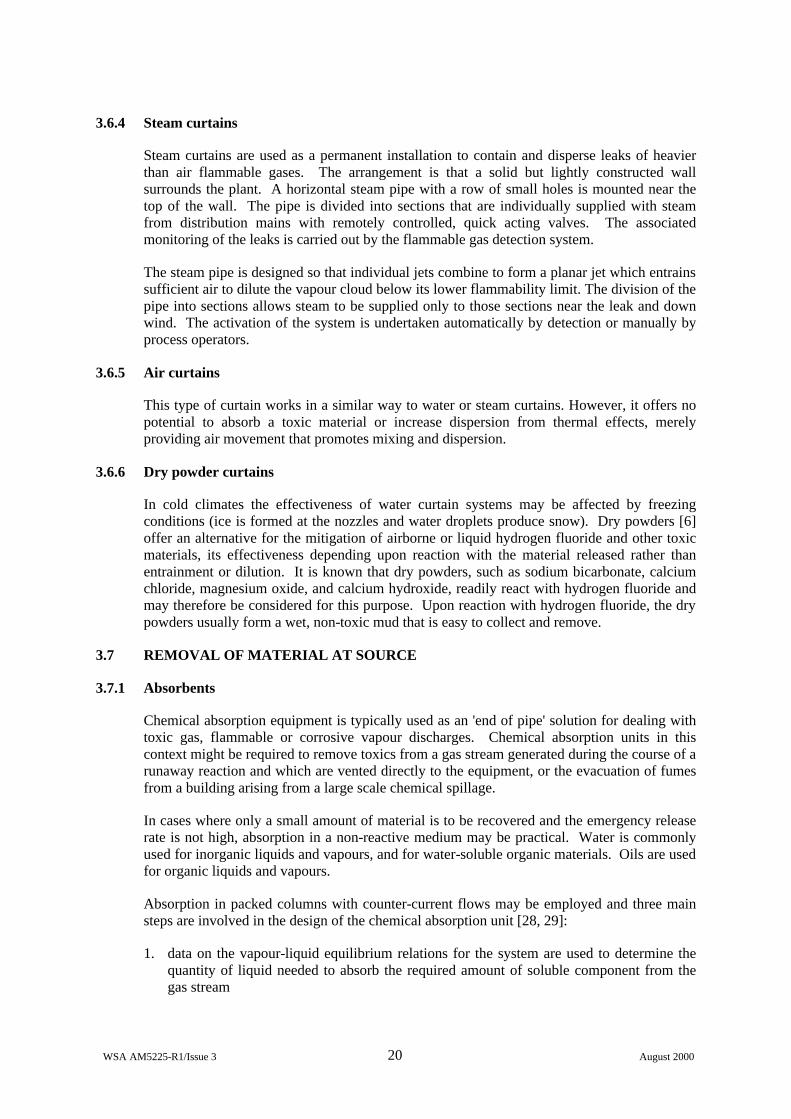
3.6.6 Dry powder curtains
In cold climates the effectiveness of water curtain systems may be affected by freezing conditions (ice is formed at the nozzles and water droplets produce snow). Dry powders [6] offer an alternative for the mitigation of airborne or liquid hydrogen fluoride and other toxic materials, its effectiveness depending upon reaction with the material released rather than entrainment or dilution. It is known that dry powders, such as sodium bicarbonate, calcium chloride, magnesium oxide, and calcium hydroxide, readily react with hydrogen fluoride and may therefore be considered for this purpose. Upon reaction with hydrogen fluoride, the dry powders usually form a wet, non-toxic mud that is easy to collect and remove.
3.7 REMOVAL OF MATERIAL AT SOURCE
3.7.1 Absorbents
Chemical absorption equipment is typically used as an 'end of pipe' solution for dealing with toxic gas, flammable or corrosive vapour discharges. Chemical absorption units in this context might be required to remove toxics from a gas stream generated during the course of a runaway reaction and which are vented directly to the equipment, or the evacuation of fumes from a building arising from a large scale chemical spillage.
In cases where only a small amount of material is to be recovered and the emergency release rate is not high, absorption in a non-reactive medium may be practical. Water is commonly used for inorganic liquids and vapours, and for water-soluble organic materials. Oils are used for organic liquids and vapours.
Absorption in packed columns with counter-current flows may be employed and three main steps are involved in the design of the chemical absorption unit [28, 29]:
1. data on the vapour-liquid equilibrium relations for the system are used to determine the quantity of liquid needed to absorb the required amount of soluble component from the gas stream
WSA AM5225-R1/Issue 3 21 August 2000
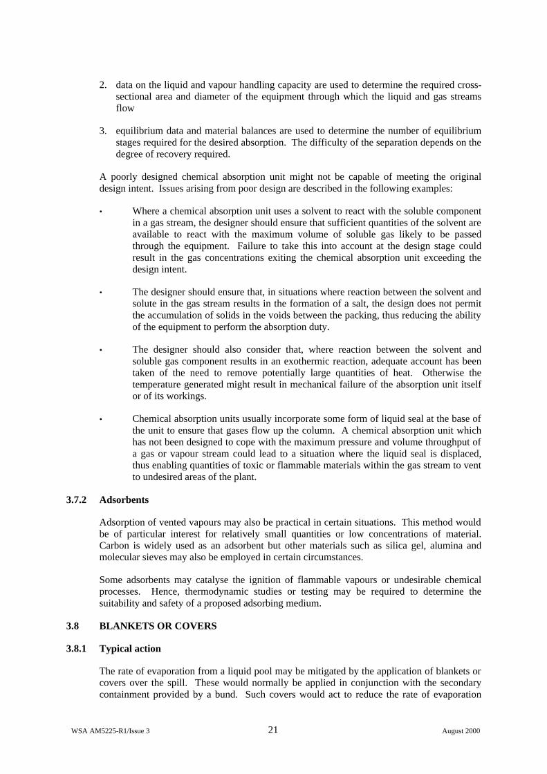
2. data on the liquid and vapour handling capacity are used to determine the required cross-sectional area and diameter of the equipment through which the liquid and gas streams flow
3. equilibrium data and material balances are used to determine the number of equilibrium stages required for the desired absorption. The difficulty of the separation depends on the degree of recovery required.
A poorly designed chemical absorption unit might not be capable of meeting the original design intent. Issues arising from poor design are described in the following examples:
• Where a chemical absorption unit uses a solvent to react with the soluble component in a gas stream, the designer should ensure that sufficient quantities of the solvent are available to react with the maximum volume of soluble gas likely to be passed through the equipment. Failure to take this into account at the design stage could result in the gas concentrations exiting the chemical absorption unit exceeding the design intent.
• The designer should ensure that, in situations where reaction between the solvent and solute in the gas stream results in the formation of a salt, the design does not permit the accumulation of solids in the voids between the packing, thus reducing the ability of the equipment to perform the absorption duty.
• The designer should also consider that, where reaction between the solvent and soluble gas component results in an exothermic reaction, adequate account has been taken of the need to remove potentially large quantities of heat. Otherwise the temperature generated might result in mechanical failure of the absorption unit itself or of its workings.
• Chemical absorption units usually incorporate some form of liquid seal at the base of the unit to ensure that gases flow up the column. A chemical absorption unit which has not been designed to cope with the maximum pressure and volume throughput of a gas or vapour stream could lead to a situation where the liquid seal is displaced, thus enabling quantities of toxic or flammable materials within the gas stream to vent to undesired areas of the plant.
3.7.2 Adsorbents
Adsorption of vented vapours may also be practical in certain situations. This method would be of particular interest for relatively small quantities or low concentrations of material. Carbon is widely used as an adsorbent but other materials such as silica gel, alumina and molecular sieves may also be employed in certain circumstances.
Some adsorbents may catalyse the ignition of flammable vapours or undesirable chemical processes. Hence, thermodynamic studies or testing may be required to determine the suitability and safety of a proposed adsorbing medium.
3.8 BLANKETS OR COVERS
3.8.1 Typical action
The rate of evaporation from a liquid pool may be mitigated by the application of blankets or covers over the spill. These would normally be applied in conjunction with the secondary containment provided by a bund. Such covers would act to reduce the rate of evaporation
WSA AM5225-R1/Issue 3 22 August 2000
from the bund. The covers themselves may be fixed or mobile and could involve various types of material such as:
• Foam
• Dry Chemicals
• Physical covers
3.8.2 Foam
Where a suitable foam is available, its use is an effective means of reducing the rate of evaporation. Foam acts by insulating the surface of the spill and preventing vaporisation. Other modes of action include absorption of the vapour and scrubbing out of aerosol and particulate matter.
Fire fighting foams may be used in ‘no-fire’ situations to suppress the release of vapours from fuels and thereby prevent the formation of a flammable concentration of vapour above the fuel. Specialist foams have also been developed to deal with a wide range of hazardous materials on which fire fighting foams are ineffective. Considerable research has been carried out on the use of aqueous foams to suppress vapours from spills of ‘non-fuel’ materials [30]. These studies concluded that, whilst conventional fire fighting foams are effective on non water-reactive materials which boil at or above 40oC, special foams are required when dealing with materials which either boil below 40oC, or are water-reactive. Best results are obtained with foam generation equipment which produces foam expansion ratios in the order of 50:1.
3.8.3 Dry chemicals
Accidental spills of certain liquids may be treated chemically using dry agents in order to form hard residues which act as a cover over the liquid. This type of treatment may be applied to either acids or caustics using suitable chemical agents which result in salt-based solid residues.
The chemical agent would normally be applied locally by site personnel using shovels or other suitable hand-portable devices, or larger wheeled or stationary units close to the liquid storage area.
3.8.4 Physical covers
Various physical covers may also be applied to accidental spills. Depending upon the nature of the liquid to be covered, the following techniques may be adopted:
• Spheres
• Water
• Sheeting
Hollow spheres (such as ping pong balls) may be applied to the surface of a spill. These would float on the surface of the liquid pool and would help to reduce the rate of vaporisation.
Water may be used to cover liquids which are more dense and are insoluble in water, e.g. bromine or carbon disulphide. The advantage of this type of cover is that the water may be pre-emptively contained within the bund and would therefore be effective immediately any release occurred. Other forms of physical blankets such as plastic sheeting may also be used to cover spills and reduce vaporisation.

WSA AM5225-R1/Issue 3 23 August 2000
4 ASSESSMENT OF CURRENT PRACTICE
4.1 SITE SELECTION
It was agreed that visits to a number of major hazard sites would be undertaken in order to determine the likely current usage of secondary containment. In order to ensure a representative coverage, the following criteria were used to allow the identification of suitable sites:
• Sites for which WS Atkins has undertaken work or for which there was some previous contact with Atkins staff.
• Between them, the sites should cover the range of hazardous materials that are of interest i.e. both toxic and flammable.
• Some sites should be included which are known to be implementing secondary containment measures.
• Only sites at which full management co-operation was forthcoming would be considered.
• HSE should approve the final list.
The final list of sites considered is given in Table 4.1.
Company Location Principal Hazardous Materials
Hickson & Welch Castleford Chlorine LPG HCl Oleum Toluene Methanol
Flexsys Rubber Wrexham Chlorine Ammonia Sodium Cyanide Phenol Aniline Acetone
Solvay Interox Warrington Hydrogen Peroxide
Aventis CropScience Norwich Bromine Ammonia Thionyl chloride Propionitrile Toluene Methanol
Site 5 UK Chlorine Di-methyl formamide Methanol
Table 4.1 : Sites selected for visits
WSA AM5225-R1/Issue 3 24 August 2000
The remainder of this section summarises some of the key issues found from these site visits. For consistency with the remainder of the report, they are grouped under the same sub headings as given in Section 3. There is also an additional section that describes those secondary containment provisions that were observed during the site visits that do not fall into any of the sub-headings from Section 3. Detailed individual site visit reports are contained in Appendix B.
4.2 BUNDS
All of the sites reported bunding around storage vessels. The bunds are generally designed in accordance with HSG50, HSG176 or with company-developed guidelines. The following issues were identified relating to bund design or operation.
4.2.1 Bund construction
Various methods of construction were observed during the site visits. Most bunds were constructed from poured concrete but some instances of brick built bunds were noted. In some cases specialist concrete was employed to minimise heat transfer. In other cases coatings were applied to the surface of the bund floor and walls. These coatings ranged from tiles to specialist coatings such as ‘furane’ or ‘ucrete’.
4.2.2 Drainage issues
One of the main operational problems encountered at one site is emptying rainwater out, and then ensuring that the drain valves are closed after use. At other sites, this problem is overcome by eliminating drain valves and emptying the bunds using steam ejectors. At another site, either steam ejectors or a mobile drainage truck is used.
Potential for bund overflowing was mentioned by one site, where leaks of hydrogen peroxide need to be diluted at source; the addition of diluting water could overwhelm the capacity of the bund.
Water was also cited as a potential problem by another site, whose Newport plant has storage of PCl3, which reacts with water. This is an example of a more general problem where it is important to keep surfaces dry when dealing with water-reactive substances.
4.2.3 Bunding of pumps
Some variation between sites was observed regarding the location of offloading and process transfer pumps. In some cases pumps were located within the main tank bund and in other cases the pumps were located outside the main bund. Clearly the advantage of the former is that any leak from the pump would benefit from the containment capacity of the main bund; however, in this configuration the pump is vulnerable to being submerged by large leaks from the main tanks. Locating the pump outside the main bund protects the pump and makes maintenance easier, but the pump would then need alternative bunding arrangements, which may not be as capacious as the main bund.
On two sites, some pumps have been located at high level such that leaks from the pump drains into the main bund, but the pump is not itself located within the bund. It was noted however that this solution may cause operational problems related to priming the pump.
Where flammable liquids are concerned, it is clearly preferable to have the pumps located outside of the main bund. This was not always the case at the sites visited.
WSA AM5225-R1/Issue 3 25 August 2000
4.2.4 Minimisation of evaporation
Whilst a bund will ensure a limited area for vaporisation, further measures can sometimes also be incorporated to minimise evaporation. At one site, the sump in a chlorine building is constructed of low conductivity concrete. There are also cases of bunds around the storage tanks of very dense liquids being deliberately filled with water. The water thus acts as a cover to reduce evaporation. This was observed for carbon disulphide and bromine.
4.2.5 Overtopping issues
The height of the bund is a key issue with respect to overtopping. One site reported some low bunds which would be inadequate to prevent either spigot flow or dynamic overtopping. Another site reported a company standard that specifies the recommended minimum distance between the bund wall and the nearest tank.
The additional loading which would result from dynamic effects has also been considered by another site, who have sunk their more recent bunds into the ground. This provides greater integrity in the event of a surge wave.
4.2.6 Bunding of flammables
The issues for flammables are slightly different from those for toxics, since a bund full of flammable liquid could ignite and result in escalation of the initial leak (e.g. to a BLEVE).
One site had very stringent company guidance on bund design for flammables which identified the following key points:
• Storage tanks are raised on pedestals
• Storage tanks are equipped with linear tape heat detectors
• Storage tanks have an automatic deluge system
• Bund is equipped with foam inductors
• Bund floor is sloped steeply towards a catchment pit at one end
• Capacity of bund is at least 110% of capacity of largest tank
• The catchment pit is separated from the main bund by a large firewall extending to the full height of the vertical tanks.
• Pumps are located outside the bunds and leaks from the pumps would drain to interceptor pits.
Another site indicated that any spillages of Highly Flammable Liquids (HFLs) into bunds would be protected by foam blankets applied by the fire brigade.
A third site reported the provision of offloading sumps capable of holding the entire contents of a failed road tanker. This would prevent running pool fires impacting on process areas.
WSA AM5225-R1/Issue 3 26 August 2000
4.2.7 Bunding of toxic liquids
Although there are no legislative requirements for the bunding of toxic liquids, all the sites visited had chosen to bund all very toxic liquids and almost all toxic liquids. This is consistent with the provision of the Health & Safety at Work Act in which it is usually considered reasonably practicable to provide bunding where this mitigates consequences. The standard of bunding varied but generally complied with the 110% rule commonly used for flammables. Exceptions tended to involve low hazard toxics, or materials that would solidify upon release.
4.2.8 Use of kerbs
One site has a small kerbed area at the drum storage, to prevent spillages entering the remaining storage area. They also indicated that tanker offloading areas were not well kerbed, and could overflow to surface water drains.
4.2.9 Compatibility of materials
Tanks containing NaBr and HBr were originally contained within a single bund at one site. However, it was realised that cyanide impurities in NaBr could react with HBr to form HCN. As a result, when an additional tank was installed, internal partitioning was introduced so that the bunding for the NaBr tanks was effectively separated from that for the HBr tanks.
4.3 ADDITIONAL SKINS
Double skinned process equipment was employed on two of the sites, and in both cases this was associated with phosgenation plant. In each case a swept air system is employed to detect leaks from the primary containment into the space within the secondary containment. It was noted that in both cases that the leak detection systems would detect the presence of a leak, but would not give an indication of the exact location of the release.
One site considered the installation of double skinned distribution pipework for chlorine. It was decided however that the associated problems with inspection of the inner pipe and the possibility for moisture build up in the annulus could be significant. It was therefore considered to be more effective to install comprehensive and efficient leak detection equipment that could be used to rapidly detect and isolate any leak that may occur.
4.4 BUILDINGS
Buildings are utilised as secondary containment on all sites visited. The nature of the containment provided by the buildings varies and includes:
• Vapour Enclosure
• Liquid Containment
• Weather Sheltering
4.4.1 Vapour enclosure
Buildings can be used to provide an enclosure to contain any vapours that are released from process equipment contained within the confines of the building. In some circumstances a forced ventilation system can also be employed in conjunction with a scrubbing system. Such provisions were in place on the two sites involving chlorine storage. The extent of the facilities within the building did however vary between the sites. On one site only the offloading area was enclosed whereas on another site the offloading area, storage area and

WSA AM5225-R1/Issue 3 27 August 2000
chlorine vaporisers were all enclosed. In both cases the buildings were equipped with chlorine detection equipment to provide a leak alarm. These buildings also incorporated containment features (see Section 4.4.2).
In some cases, where buildings are being used for secondary containment purposes in conjunction with forced ventilation systems, the building had restricted entry provisions, interlocks and in some cases CCTV surveillance.
On one site the use of temporary tenting during maintenance activities was reported. Such tenting was vented through activated carbon. Whilst this is a useful technique, the expense of providing sufficient activated carbon to deal with accidental release rates is likely to be considerable.
4.4.2 Containment
In some cases buildings were effectively used as bunds to contain liquid spills. These often also incorporated special treatments or construction materials for the floor (and partially the walls) of the building. In the case of chlorine low conductivity concrete was used to minimise heat transfer. Where oleum storage was concerned, a plastic (furane) coating was applied.
4.4.3 Weather sheltering
On one site, a building is employed to provide sheltering and prevent rain water from coming into contact with liquid spills. The building encloses the offloading facilities for a number of chlorides, the contact of which with water would greatly increase the rate of evolution of HCl vapour.
4.5 EMERGENCY RELIEF
Most of the sites reported the use of emergency relief systems. These included:
• Bursting discs / relief valves
• Catchtanks
• Cyclones
• Dump tanks
• Quench vessels
Some sites incorporated double bursting disc arrangements for which the inter-spatial pressure is monitored. Cases of bursting discs followed by relief valves were also reported. In one case a bursting disc / relief valve configuration relieved via a catchtank. In another process, which has the potential for runaway reactions to occur, the bursting discs discharge to a quench tank.
Other instances of quench vessels and dump tanks were also reported for the more ‘high risk’ processes. On one site a separate towns water header was installed to provide an emergency water supply in the case of site power failure.
One site reported the retro fitting of cyclones to column vents in order to prevent the potential for droplet solvent discharge to atmosphere during venting.
WSA AM5225-R1/Issue 3 28 August 2000
4.6 BARRIERS
All sites reported the potential use of mobile water sprays to knock down vapour clouds. Although all sites visited had their own site emergency response teams who are trained and equipped to provide water curtains in this way, on only one site did the emergency team routinely set up the water spray equipment during offloading activities (involving ammonia) as a pre-emptive measure.
Only one site claimed mitigation potential involving solid barriers. In this case the nature of the site geography results in potential dispersion of a heavy gas (chlorine) towards populated areas up a steep gradient. In these circumstances, a high solid fence on the site perimeter would form an effective barrier and could act to contain a significant amount of the gas within the site boundary.
4.7 REMOVAL OF MATERIAL AT SOURCE
All sites reported the provision of various absorbing materials that could be utilised for small spills. These include:
• Bicarbonate of soda
• Sand bags
• Absorbent pads
• Absorbent socks
• Wood chips
One site reported the use of scrubbers for all off-gases and in some cases both primary and secondary scrubbers are employed.
4.8 OTHER MEASURES IDENTIFIED
4.8.1 Site design
All sites reported some degree of secondary containment provided by the actual design of the site. In most cases this containment related to site drainage designed to prevent local environmental contamination arising from the discharge of off-specification liquid or firewater run-off. All sites had on-site water treatment facilities.
4.8.2 Covers
The use of emergency drain covers was reported on two sites. On one site the drain covers were pre-installed and deployed by means of a central locking mechanism. On the other site mobile covers were supplied at various strategic locations around the site.
4.8.3 Flange guards
The use of flange guards was reported on only one site, where they were used extensively on the distribution pipework for caustics. Two types of flange guard were being employed, the original type consisting of a jacket that fits around the entire flange including the bolts. However, some problems with bolt corrosion had previously been experienced with this type of guard, and more recently a wrap around tape style of guard has been introduced which leaves the bolts exposed.
WSA AM5225-R1/Issue 3 29 August 2000
It was noted that the flange guards were fitted for personnel protection purposes rather than as a secondary containment provision. This point was re-iterated by another site which, whilst not having a policy to fit flange guards, had recently considered this issue following an incident in which caustic was lost from pipework. The conclusion was that flange guards would merely act to delay an accidental release.
4.8.4 Mobile devices
All sites reported the use of various types of mobile device that could be deployed on demand for various scenarios. These included mobile bunds, various types of absorbent materials and mobile covers as described in the above sections.
In addition, the following mobile devices were also noted on some of the sites visited:-
• Spill pallets for temporary drum storage
• Mobile pumps
• Overdrums
• Drum clamps and patches
• Pneumatic patches for bulk tanks or pipes
4.8.5 Underground tanks
Two sites reported the use of underground tanks.
In one case this was used as containment for surface water run off near the site gate house. This provides secondary containment for any leaks that may occur from road tankers in this area.
A second site was equipped with an underground tank designed to accept leaks of bromine, that are initially collected below a layer of water, in a bromine storage containment pit. The underground tank is equipped with a number of dip pipes at various levels which allow the bromine to be removed for treatment involving a minimum amount of fluid volume.
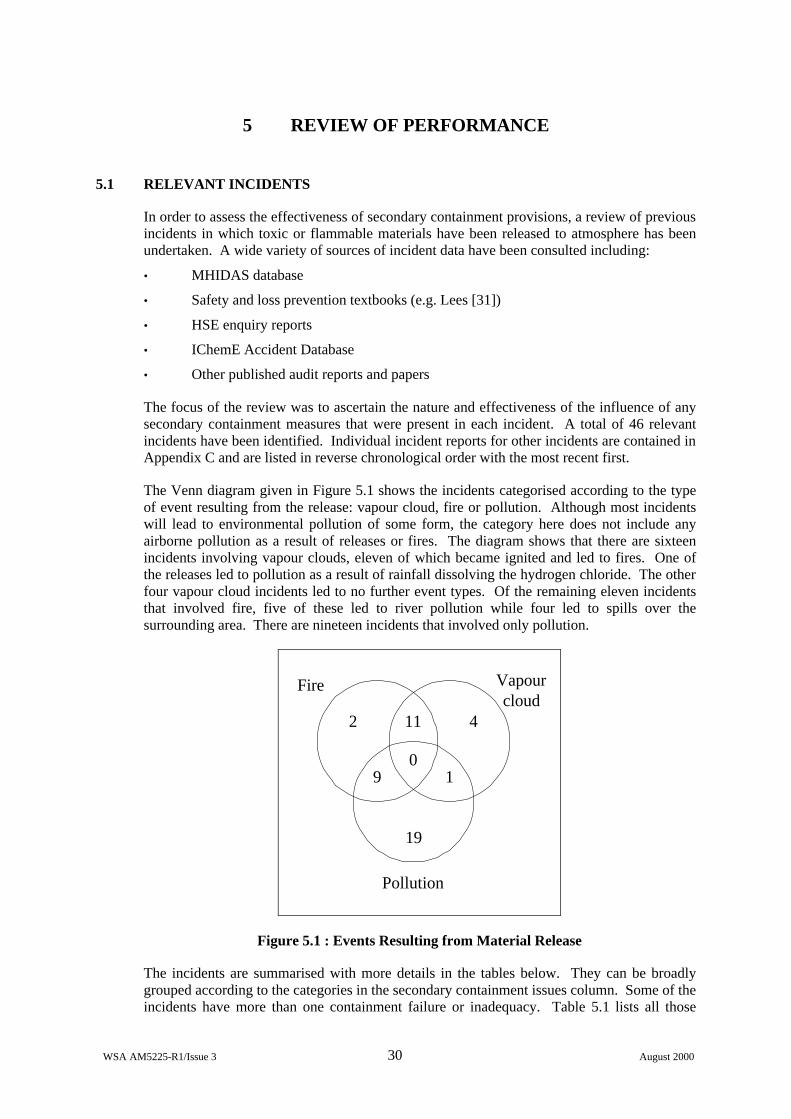
WSA AM5225-R1/Issue 3 30 August 2000
5 REVIEW OF PERFORMANCE
5.1 RELEVANT INCIDENTS
In order to assess the effectiveness of secondary containment provisions, a review of previous incidents in which toxic or flammable materials have been released to atmosphere has been undertaken. A wide variety of sources of incident data have been consulted including:
• MHIDAS database
• Safety and loss prevention textbooks (e.g. Lees [31])
• HSE enquiry reports
• IChemE Accident Database
• Other published audit reports and papers
The focus of the review was to ascertain the nature and effectiveness of the influence of any secondary containment measures that were present in each incident. A total of 46 relevant incidents have been identified. Individual incident reports for other incidents are contained in Appendix C and are listed in reverse chronological order with the most recent first.
The Venn diagram given in Figure 5.1 shows the incidents categorised according to the type of event resulting from the release: vapour cloud, fire or pollution. Although most incidents will lead to environmental pollution of some form, the category here does not include any airborne pollution as a result of releases or fires. The diagram shows that there are sixteen incidents involving vapour clouds, eleven of which became ignited and led to fires. One of the releases led to pollution as a result of rainfall dissolving the hydrogen chloride. The other four vapour cloud incidents led to no further event types. Of the remaining eleven incidents that involved fire, five of these led to river pollution while four led to spills over the surrounding area. There are nineteen incidents that involved only pollution.
4
1
11
0
19
2
9
Vapourcloud
Fire
Pollution
Figure 5.1 : Events Resulting from Material Release
The incidents are summarised with more details in the tables below. They can be broadly grouped according to the categories in the secondary containment issues column. Some of the incidents have more than one containment failure or inadequacy. Table 5.1 lists all those
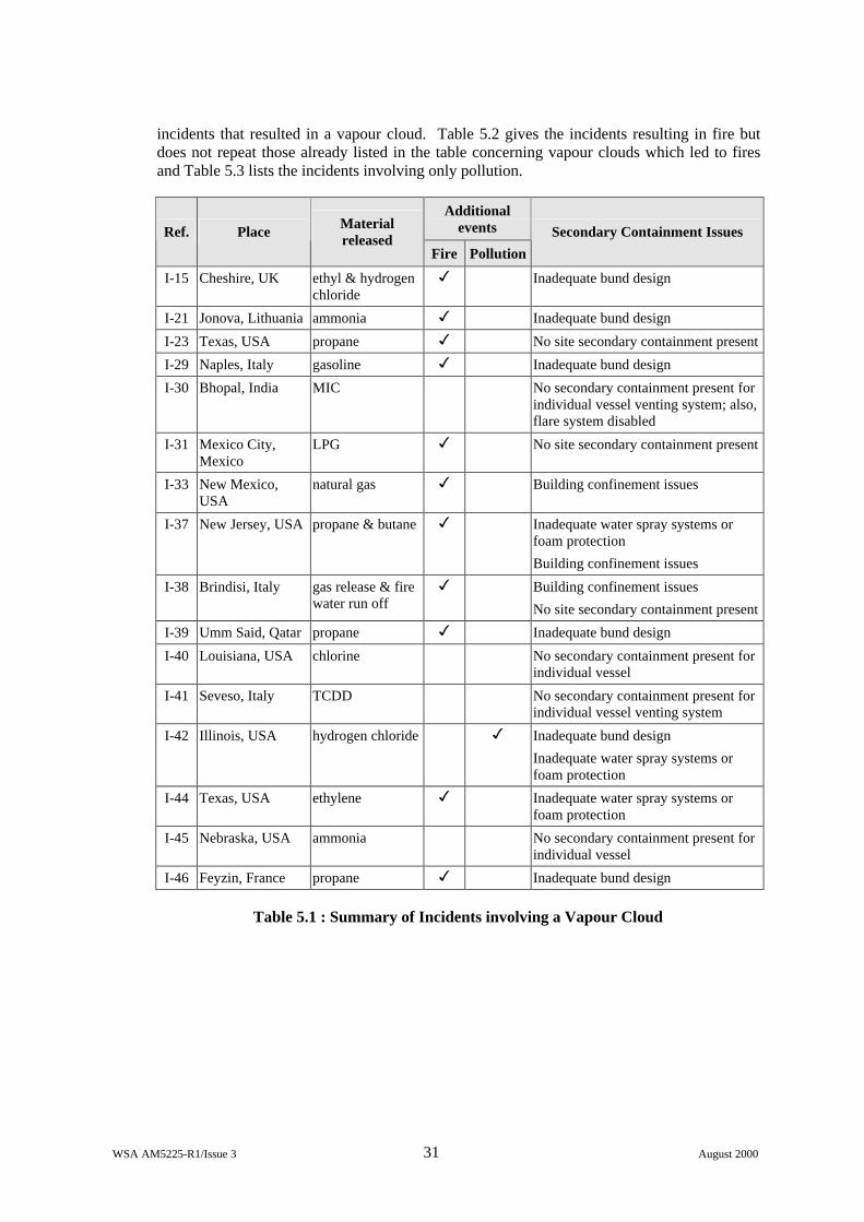
WSA AM5225-R1/Issue 3 31 August 2000
incidents that resulted in a vapour cloud. Table 5.2 gives the incidents resulting in fire but does not repeat those already listed in the table concerning vapour clouds which led to fires and Table 5.3 lists the incidents involving only pollution.
Additional events Ref. Place Material
released Fire Pollution
Secondary Containment Issues
I-15 Cheshire, UK ethyl & hydrogen chloride
3 Inadequate bund design
I-21 Jonova, Lithuania ammonia 3 Inadequate bund design
I-23 Texas, USA propane 3 No site secondary containment present
I-29 Naples, Italy gasoline 3 Inadequate bund design
I-30 Bhopal, India MIC No secondary containment present for individual vessel venting system; also, flare system disabled
I-31 Mexico City, Mexico
LPG 3 No site secondary containment present
I-33 New Mexico, USA
natural gas 3 Building confinement issues
I-37 New Jersey, USA propane & butane 3 Inadequate water spray systems or foam protection
Building confinement issues
I-38 Brindisi, Italy gas release & fire water run off
3 Building confinement issues
No site secondary containment present
I-39 Umm Said, Qatar propane 3 Inadequate bund design
I-40 Louisiana, USA chlorine No secondary containment present for individual vessel
I-41 Seveso, Italy TCDD No secondary containment present for individual vessel venting system
I-42 Illinois, USA hydrogen chloride 3 Inadequate bund design
Inadequate water spray systems or foam protection
I-44 Texas, USA ethylene 3 Inadequate water spray systems or foam protection
I-45 Nebraska, USA ammonia No secondary containment present for individual vessel
I-46 Feyzin, France propane 3 Inadequate bund design
Table 5.1 : Summary of Incidents involving a Vapour Cloud
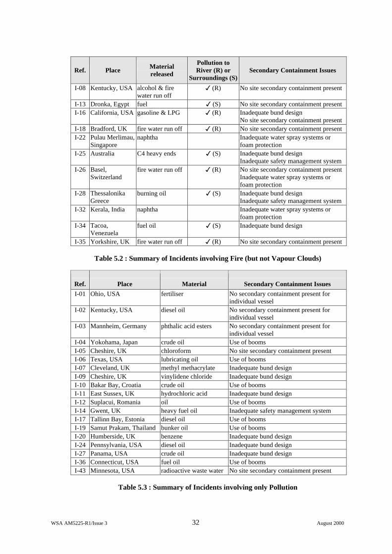
WSA AM5225-R1/Issue 3 32 August 2000
Ref. Place Material released
Pollution to River (R) or
Surroundings (S) Secondary Containment Issues
I-08 Kentucky, USA alcohol & fire water run off
3 (R) No site secondary containment present
I-13 Dronka, Egypt fuel 3 (S) No site secondary containment present I-16 California, USA gasoline & LPG 3 (R) Inadequate bund design
No site secondary containment present I-18 Bradford, UK fire water run off 3 (R) No site secondary containment present I-22 Pulau Merlimau,
Singapore naphtha Inadequate water spray systems or
foam protection I-25 Australia C4 heavy ends 3 (S) Inadequate bund design
Inadequate safety management system I-26 Basel,
Switzerland fire water run off 3 (R) No site secondary containment present
Inadequate water spray systems or foam protection
I-28 Thessalonika Greece
burning oil 3 (S) Inadequate bund design Inadequate safety management system
I-32 Kerala, India naphtha Inadequate water spray systems or foam protection
I-34 Tacoa, Venezuela
fuel oil 3 (S) Inadequate bund design
I-35 Yorkshire, UK fire water run off 3 (R) No site secondary containment present
Table 5.2 : Summary of Incidents involving Fire (but not Vapour Clouds)
Ref. Place Material released
Secondary Containment Issues I-01 Ohio, USA fertiliser No secondary containment present for
individual vessel I-02 Kentucky, USA diesel oil No secondary containment present for
individual vessel I-03 Mannheim, Germany phthalic acid esters No secondary containment present for
individual vessel I-04 Yokohama, Japan crude oil Use of booms I-05 Cheshire, UK chloroform No site secondary containment present I-06 Texas, USA lubricating oil Use of booms I-07 Cleveland, UK methyl methacrylate Inadequate bund design I-09 Cheshire, UK vinylidene chloride Inadequate bund design I-10 Bakar Bay, Croatia crude oil Use of booms I-11 East Sussex, UK hydrochloric acid Inadequate bund design I-12 Suplacui, Romania oil Use of booms I-14 Gwent, UK heavy fuel oil Inadequate safety management system I-17 Tallinn Bay, Estonia diesel oil Use of booms I-19 Samut Prakam, Thailand bunker oil Use of booms I-20 Humberside, UK benzene Inadequate bund design I-24 Pennsylvania, USA diesel oil Inadequate bund design I-27 Panama, USA crude oil Inadequate bund design I-36 Connecticut, USA fuel oil Use of booms I-43 Minnesota, USA radioactive waste water No site secondary containment present
Table 5.3 : Summary of Incidents involving only Pollution
WSA AM5225-R1/Issue 3 33 August 2000
For this report, the main areas of interest are incidents involving toxic and flammable releases. For both types of incident the initial aim is to keep the release as small as possible. In the case of liquid releases, steps need to be taken to reduce vaporisation as much as possible. This is achieved in different ways such as blanketing the release with foam or ensuring rapid drainage of the spill away from any danger areas. This also helps to prevent BLEVE situations and running pool fires if the liquid is flammable. The site should be designed so that congestion is eliminated around areas that contain flammable materials. Toxic releases need to be neutralised. The best option may be to house storage vessels containing toxic materials in an enclosed building, therefore preventing immediate release to the environment. In the case of gaseous releases, the use of water spray systems or steam curtains may help to disperse the vapour.
5.2 CONSIDERATION OF SECONDARY CONTAINMENT FAILURES
5.2.1 Lack of secondary containment provisions
About a third of the incidents involve a lack of secondary containment provision. These can be split into those that lack containment around individual vessels and those which involve sites that do not have any general secondary containment provisions.
No secondary containment present for individual vessels
There are seven incidents that fall into this category. In three of the cases (I-01: Ohio, I-02: Kentucky and I-03: Mannheim) there was a release from a storage unit either due to vessel rupture or inadequately maintained process equipment. If bund walls had been present around these units, the various chemicals – fertiliser, diesel oil and phthalic acid esters – would not have been released from the site and hence contaminated the surrounding environment.
The above incidents involve liquid releases, but secondary containment provisions for gases are also important as demonstrated by the following four incidents (I-30: Bhopal, I-40: Louisiana, I-41: Seveso and I-45: Nebraska). These involved releases of methyl isocyanate (MIC), chlorine, TCDD and ammonia respectively. At Bhopal, the release of MIC gas from a relief valve on a storage tank was the most devastating of these incidents, resulting in 2000 deaths and thousands of people injured. A bursting disc on a reactor at Seveso caused the release of a vapour cloud containing TCDD, which led to animals dying and people falling ill. If there had been some sort of containment to retain the released vapours and direct them through appropriate scrubbers, the results would have been less severe and the deaths and environmental contamination could have been prevented. The losses of chlorine (Louisiana) and ammonia (Nebraska), which did not leak from specific valves but were generally released, would have been very difficult to contain. Fortunately these did not lead to any deaths or serious injuries although in both cases large vapour clouds were formed. Despite the increased difficulty in containing a vapour rather than a liquid, systems should be in place to hold releases from relief valves or bursting discs if the process involves dangerous or toxic gases.
No site secondary containment present
These incidents involve releases from the site rather than the specific failure of one vessel. In one incident (I-05: Cheshire) 144 tonnes of chloroform were lost via a leaking pipe, resulting in contamination of the groundwater and nearby rivers. Another incident (I-43: Minnesota) involved a large loss of radioactive wastewater to a river when the water storage space was over filled.
WSA AM5225-R1/Issue 3 34 August 2000
There are six incidents listed (I-16: California, I-18: Bradford, I-26: Basel, I-35: Yorkshire, I-38: Brindisi and I-43: Minnesota) where the sites did not have sufficient provision for the large volumes of fire fighting water used on the plant. This resulted in run off water containing various different contaminants such as alcohol, petroleum, and mercury compounds, leaving the site and polluting nearby rivers. If drainage systems had been in place on these sites, none of these incidents would have led to releases to the environment.
A few incidents involve fires that have spread as a result of little or no containment. The first of these (I-08: Kentucky) involves a warehouse fire that spread around the site due to flowing burning alcohol. There were no trenches or bunds on site to retain the spill. The resulting damage may have been reduced if fire sprinkler systems had been in place throughout the warehouses and site buildings to contain the fire. The second incident (I-13: Dronka) occurred on a liquid fuel depot and resulted in blazing fuel flowing into the village killing at least 410 people. This spillage would probably have been prevented if site containment had been in place to retain the fuel. The last incident (I-31: Mexico City) originated with a gas release igniting and leading to site fires. Storage spheres of LPG BLEVEd and burning pools of liquid collected under adjacent vessels resulting in further explosions. If proper bunding and drainage systems had been in place across the site, the spread of burning liquid would have been decreased and the consequences would have been reduced.
There is one incident (I-23: Texas) where the ignition of a propane vapour cloud led to an intense fire, which enveloped four blending tanks. The fire spread a distance of 1300 feet through a trench. There were difficulties isolating the tanks and pipelines. A drainage system should have been in place to remove the burning liquid and the site layout should have enabled vessel areas to be readily isolated preventing the fire spreading to other areas. Flame arresters may also have helped to reduce the spread of the fire.
5.2.2 Inadequacy of design
Approximately half of the incidents involve inadequately designed secondary containment or site layout. These incidents have been split further according to the type of containment; bunds, water spray and foam systems, or vessel isolation. Bunds are the most common containment type and consequently a large number of incidents involving bunds were found.
Inadequate bund design
There are sixteen incidents that involve some sort of bund failing through inadequate design. Five of the incidents (I-15: Cheshire, I-28: Thessalonika, I-29: Naples, I-34: Tacoa and I-46: Feyzin) involve bunds that enabled liquid pools to collect below the vessel before being ignited. Bunds should be shaped in such a way as to ensure rapid drainage of any spills away from the vessel in order to prevent escalation. In one case the burning fuel at the base of the tank led to a massive boilover and further site devastation.
There are five incidents (I-11: Sussex, I-20: Humberside, I-24: Pennsylvania, I-25: Australia and I-39: Qatar) where the bund was too small to contain the vessel spillage. This resulted in pollutants such as hydrochloric acid, benzene and diesel entering rivers. In the last of these incidents a wave of liquid propane swept over the bund wall and boiled on the sand; the resulting vapour cloud entered an adjacent plant and ignited. This led to a massive fire that took 8 days to extinguish and killed seven people. Clearly the bund walls should be sized suitably so that they hold the total vessel contents with allowances made for the wave effect that may occur if the release is catastrophic.
There are also two incidents (I-16: California and I-42: Illinois) where the bund could not hold the spill as well as the additional materials used such as fire fighting water and lime for
WSA AM5225-R1/Issue 3 35 August 2000
neutralisation. In the first incident the bund was breached releasing the water and petroleum mixture to the river. In the second incident a further pit had to be dug to take the overflow from the bund.
A couple of the incidents (I-21: Lithuania and I-27: Panama) involved bund walls that were destroyed. The first of these occurred when a storage tank smashed through a surrounding reinforced concrete retention wall and released a large quantity of ammonia. In the second case a tank containing crude oil ruptured and the force of the released oil caused a section of the bund to collapse, releasing oil to the site and surrounding environment.
The last two incidents in this category (I-07: Cleveland and I-09: Cheshire) resulted in seepage from bunds due to site problems or errors. Both of these led to releases to the environment, one of which resulted in prosecution.
Inadequate water spray systems or foam protection
There are two incidents (I-37: New Jersey and I-44: Texas) where water spray systems were in place and fully functional but were ineffective at dispersing the vapour clouds. This resulted in explosions on the site when the vapour became ignited. In a third incident (I-15: Cheshire), a foam blanket was used, but it is understood that ignition occurred as it was being laid.
Four incidents (I-22: Singapore, I-26: Basel, I-32: Kerala and I-42: Illinois) involved the use of foam protection systems, which did not prove to be highly effective in containing or extinguishing the fires. In the first of these incidents, ignition occurred as the foam blanket was being applied. A water curtain that was meant to protect against radiated heat also proved to be ineffective.
5.2.3 Safety management system issues
This group of incidents occurred as a result of a poor site safety management system or inappropriately designed containment.
Three incidents originate from a lack of site communication or as a result of nearby maintenance. The first incident (I-14: Gwent) involved a situation where there was no communication between the staff on site and the delivery company. The fuel oil was pumped into a tank that was undergoing maintenance, as was the surrounding bund wall, and a large spillage resulted. The other two incidents (I-25: Australia and I-28: Thessalonika) occurred as a result of maintenance (flame cutting and hot work respectively) taking place in close proximity to flammable materials, which then led to site fires.
The next three incidents involved building confinement issues. The first one (I-33: New Mexico) occurred following a release of natural gas from a compressor. The gas was confined within a building and ignited leading to an explosion that injured two operators. In this case the equipment might have been more suitably positioned outside, allowing any gas releases to disperse; although the possibility of ignition would still exist, the consequences may have been less severe. The second incident involved propane and butane vapours filling a control room, which then exploded. There is also an incident (I-38: Brindisi) where an ignited release from an ethylene unit resulted in severe blast damage. This may have been avoided if the unit had been placed somewhere less confined.
WSA AM5225-R1/Issue 3 36 August 2000
Use of booms
There are seven incidents (I-04: Japan, I-06: Texas, I-10: Croatia, I-12: Romania, I-17: Estonia, I-19: Thailand and I-36: Connecticut) where booms have been used to contain spillages of oil at sea. They have various rates of success but do not provide a means of total recovery of the oil spill. For most of the incidents the booms helped to stop the slick spreading any further, although bad weather did hamper some efforts.
5.3 VAPOUR CLOUD MITIGATION
The incidents leading to vapour cloud formation had various levels of secondary containment provision and some had more than one containment failure or design inadequacy. Of the sixteen incidents that led to vapour cloud formation, five of these did not have any secondary containment in place to deal with the release. For two of these incidents (I-30: Bhopal and I-41: Seveso), the provision of some form of containment to retain the gas released from the vessel venting system could have reduced the effects significantly. The MIC gas and TCDD would not have formed such large vapour clouds and there would have been fewer deaths and less environmental contamination. The retained gases could then have been redirected through the process system or passed through appropriate scrubbers before being released to the environment.
Two of the other incidents involving releases (I-40: Louisiana and I-45: Nebraska) would have been more difficult to contain as the vapours did not escape through a venting system such as a relief valve or bursting disc, but from the vessel itself. The releases of chlorine and ammonia respectively may have been adequately contained if the vessels had been located inside buildings. However, there are also incidents showing that building confinement may not be the safest option for certain materials. This is demonstrated by the next three incidents (I-33: New Mexico, I-37: New Jersey and I-38: Brindisi). The first of these involved a release into a building of natural gas which then ignited and exploded. The second incident occurred when a release of propane and butane formed a vapour cloud and filled a control room, also resulting in an explosion. In the last incident, a major gas release from an ethylene unit was ignited causing severe blast and fire damage. If the unit had been positioned in a less confined area, the resulting damage could have been reduced. This confirms that vessels with the potential to release flammable vapours are best positioned outside, and well away from any congested areas.
There are three incidents related to inadequate water spray systems or foam protection. In two of the incidents (I-37: New Jersey and I-44: Texas), water sprays were present but they were ineffective in dispersing the vapours. The last of these incidents (I-42: Illinois) involved a release of silicon tetrachloride which formed an irritant cloud containing hydrogen chloride. Foam was added to blanket the released liquid in the bund but this failed, although vaporisation was subsequently reduced dramatically after fuel oil and lime were added. In the case of these incidents, the water spray and foam protection systems did not fulfil their requirements of dispersing the vapour and preventing evaporation respectively. The systems therefore did not prove to be a very effective source of secondary containment for vapour cloud mitigation.
Inadequate bund design was one of the main contributors leading to incidents that involve vapour cloud formation. Three of the incidents (I-15: Cheshire, I-29: Naples and I-46: Feyzin) occurred where the bunds did not drain away the spilt liquid swiftly but allowed pools of ethyl chloride, gasoline and propane respectively, to collect. Despite efforts to suppress the further release of ethyl chloride vapours in the first incident, a pool of liquid continued to collect providing more vapours. For the second incident, the gasoline spillage occurred in a confined area and covered the bund area. The high temperature and low wind speed resulted
WSA AM5225-R1/Issue 3 37 August 2000
in the formation of a large vapour cloud. In the last incident, an uncontrolled release of propane led to further releases after ignition had occurred and escaping liquid accumulated beneath the storage sphere.
Two incidents (I-21: Lithuania and I-39: Qatar) occurred when the secondary containment present was unable to retain the release. The first of these incidents happened when an ammonia tank smashed through the retention wall spilling large quantities of ammonia, which then evaporated. The second incident involved a wave of propane liquid that swept over the bund wall and boiled on the sand beyond the wall. Again, the design was inadequate, in this case to withstand the dynamic effects of the released propane, and hence to prevent overtopping.
These incidents show the importance of proper bund design and drainage systems. Bund walls should be built to retain the entire spillage making them useful for the prevention of spreading and therefore reducing the pool area available for evaporation. This slows down the formation of vapour clouds. Drainage systems that remove the liquid rapidly away from the danger area are highly effective as they reduce the amount of vaporisation possible from surface pools. They also remove the danger of any liquid igniting and heating the vessel contents, which can lead to further releases and BLEVEs.
5.4 FIRE SPREAD AND SEVERITY
This section considers those incidents that led to fires but did not involve vapour clouds. The eleven incidents had a variety of secondary containment weaknesses and only two of them did not lead to some form of pollution.
Six of the incidents had no secondary containment present for the site as a whole. For the first couple of incidents, the lack of secondary containment provision led to the fire spreading across the site. The first incident (I-08: Kentucky) occurred at a whiskey warehouse where an 18 inch deep flood of flaming bourbon covered the main road and spread the fire across the site. The second incident (I-13: Egypt) involved blazing fuel from a depot flowing into a village and killing over 410 people. These incidents clearly demonstrate that, if well designed site containment had been provided, the fire spread would have been significantly reduced, resulting in less fire damage and loss of life.
For the next four incidents, the lack of secondary containment was more a pollution issue than a fire spreading one. For each of the incidents the amount of fire fighting water used led to site containment problems. The first incident (I-18: Bradford) involved the site drains becoming blocked after the store products reacted with water. The fire fighting and cooling water could not be contained on the site and resulted in significant river pollution. The next three incidents (I-16: California, I-26: Basel and I-35: Yorkshire) resulted in chemicals being carried into rivers with the large amounts of fire fighting water which could not be contained on the site. These incidents show the need for adequate containment on site to retain the large amounts of fire water that may be required and therefore prevent pollution to any nearby rivers and the surrounding area.
Inadequate bund design contributed to four of the incidents. In the first incident (I-28: Thessalonika) an oil spillage in a bund was ignited and led to a small fire. Accumulated oil from previous spillages and the existence of common drainage channels through bund walls allowed the fire to spread into adjacent areas. The second incident (I-34: Venezuela) involved an explosion that blew the roof off a fuel oil storage tank, which then burst into flames. Other oil lines were severed allowing more oil to enter the bund where it ignited, adding to the fire. Burning oil was spread a long way by the explosion. These two incidents clearly show the need for good bund design and adequate drainage taking away old spills to prevent fire
WSA AM5225-R1/Issue 3 38 August 2000
escalation and spreading. This should also help to reduce the possibility of fires leading to BLEVEs.
The next incident (I-25: Australia) involved a fire at the base of a tank that ignited flammable vapours. This led to an explosion which released a large amount of flaming C4 heavy ends. The bund did not have sufficient capacity and the flaming liquid overflowed to the surrounding area. The last incident (I-16: California) occurred when a bund was breached due to the large amount of fire fighting water used, resulting in the petroleum and water mixture spilling into the river. Suitably designed bund walls should have prevented both these releases and therefore reduced the damage and pollution to the surrounding area.
There are three incidents (I-22: Singapore, I-26: Basel and I-32: Kerala) that involved the use of foam systems. The indications from these three cases are that the foam systems did not prove to be effective in either containing or extinguishing the fires. In the first incident, a water curtain between the tanks to protect against radiated heat also proved to be ineffective.
Two of the incidents (I-25: Australia and I-28: Thessalonika) involved inadequate safety management systems. Both of these occurred due to maintenance work – flame cutting and hot work respectively – taking place in close proximity to vessels containing hydrocarbons. In both cases ignition occurred, leading to fires and explosions. This highlights the importance of good safety management systems on the site. If the maintenance work is likely to be a source of ignition, gas detectors should be used to warn of any possible danger. If possible, vessels containing flammable materials in the area of maintenance work should be drained.
5.5 INCIDENTS IDENTIFIED DURING SITE VISITS
In addition to the 46 incidents identified during the review of incidents described above, a number of incidents were also identified during the site visits that were undertaken as part of this study. Individual reports for these incidents are contained within the respective site visit reports in Appendix B. The reports from the 5 site visits presented in Appendix B provide a further 13 incidents (or types of incident) involving secondary containment issues. These are summarised and discussed in the following sections
5.5.1 Hickson & Welch
The visit to Hickson & Welch at Castleford identified two incidents, both of which involved bunds. In the first incident, a bund drain valve was left open and a remote computer controlled operation resulted in a leak of methanol. The methanol flowed out of the bund through the open drain valve and created a spillage across a site roadway.
The second incident involved a GRP storage tank containing nitric acid, which failed. The leak was contained in the bund but the acid attacked the connections and seals on some adjacent dichloromethane storage tanks, which then also released their contents. The bund was only designed to hold 110% capacity of a single tank but fortunately the tanks were not full at the time of the incident and the combined release was contained within the bund, preventing a major spill. This clearly indicates that care must be taken to ensure that the release of corrosives would not affect nearby storage of toxic materials.
5.5.2 Flexsys
The visit to Flexsys at Ruabon identified four incidents. The first of these involved an underground effluent pipe that developed a leak allowing aniline to flow into the River Dee.
WSA AM5225-R1/Issue 3 39 August 2000
As a result of this incident, all underground pipework carrying strong effluent was raised above ground.
The second incident involved a release of hydrogen sulphide from a vent stack when a process instrumentation failure occurred. The relief system vented directly to atmosphere.
The next incident occurred when a storage tank containing a white spirit type solvent developed a leak. The bund around the vessel had an annulus type of support for the tank that was filled with bitumen and rubble. The leak ran into this annulus and bypassed the bund.
The final incident on this site involved a chlorine leak from a transfer line due to corrosion. A passing worker saw the leak and initiated an emergency shutdown. The chlorine transfer system has since been redesigned.
5.5.3 Solvay Interox
The visit to Solvay Interox identified several incidents that fall into five basic types. The first type is ‘site fire’ of which the site suffered a series of three in the 1980’s, one of which resulted in the loss of the entire process plant. In each fire there was no significant offsite damage due to aerial release or firewater run-off. The plant has subsequently been rebuilt with much greater separation between processes to reduce the probability of escalation of such fires to involve adjacent plant in the future.
The second type of incident is off-site releases of solvents from dump pits. These were all associated with false fire alarms triggering sequences of events that resulted in collected liquids being discharged via a penstock valve (alternatively known as a sluicegate valve).
The third type of incident involves aerial release of solvents during emergency relief of columns. Cyclones have subsequently been fitted to relevant vents.
A fourth incident occurred when an oxidiser column foamed over. This flooded the carbon absorbers and resulted in the release of a solvent aerosol.
A fifth incident involved the overfilling of a road tanker. This was due to incorrect setting of the tanker capacity and resulted in a spillage of hydrogen peroxide local to the loading area.
5.5.4 Aventis CropScience UK Limited
The visit to Aventis CropScience identified two minor incidents. The first involved a release into a bund which was not contained because a drainage valve had inadvertently been left open.
In the second incident, a release of caustic occurred from a process flange. The release dripped through occupied process areas since the floorings were grated. Although no one was injured, this incident raised the issue of the incorporation of flange guards to enhance the protection of personnel from such releases.
5.5.5 Site 5
No incidents relevant to secondary containment were identified during the visit to the fifth site.
WSA AM5225-R1/Issue 3 40 August 2000
6 CALCULATION METHODOLOGIES
6.1 BACKGROUND
This section summarises the various calculation methodologies that may be used to assess the effects of secondary containment measures on the source terms adopted in risk assessment studies. The calculation methods have been described and, where available, the results and conclusions obtained from the implementation of the methodologies are discussed.
The incorporation of the secondary containment measures identified in this report should enable the effects of accidental releases to be reduced. Whilst this would in many cases relate to the prevention or reduction of pollution to the local area, the situations of greatest interest in this study are major hazard events in which immediate risks to the local population would be reduced. The quantification of such a reduction may be important in some circumstances, for example where a QRA is undertaken as part of a site safety case, as input to an emergency plan, or when considering risk-affected planning issues. Such quantification can be undertaken in a number of ways and may include a number of considerations such as:
• Consequence Reduction • Frequency Considerations • Risk Reduction
The following sub-sections follow, as far as possible, the format of Section 3. There is, however, an additional sub-section relating to the effects of secondary containment on fire sizes. In this case, although it could be related to bunding, the issues considered are more affected by kerbing, channelling and other site detail.
6.1.1 Consequence reduction
In many cases, there will be an obvious reduction in the consequences of an accidental release. Typical examples would be a bund reducing the evaporation rate of a volatile material (see Section 6.2.1) and hence giving reduced hazard ranges. Examples of such calculations have been presented by CCPS [6], and discussed in Section 2.4.3. They are included, together with other examples of the use of similar methodologies, in the following subsections.
6.1.2 Frequency considerations
Secondary containment measures generally have little effect on the frequency of the release which would be considered as part of a QRA. However, there may be circumstances in which frequencies of knock-on events may be modified. A typical example here is that the provision of adequate drainage away from tanks containing flammable gases could significantly reduce the probability of a BLEVE.
A further area in which frequency may need to be considered is when assessing the reliability or availability of secondary containment measures. This is particularly important when active measures, such as water sprays, foam blankets, etc are deployed.
6.1.3 Risk reduction
The reduction in consequences will generally imply a reduction in risk. However, although hazard ranges may be reduced, it is possible, for example, that plume widths are increased.
WSA AM5225-R1/Issue 3 41 August 2000
The overall effects on risk may therefore not be as straightforward as would be implied by simple consequence modelling calculations.
In addition, the frequency considerations discussed above will need to be incorporated in order to give the complete risk picture.
In order to demonstrate the use of the methodologies described in this section, and to indicate how risks would be affected, three example risk assessments have been used. These were described in detail by Lines et al [32], and cover the following materials:
• Chlorine (liquefied toxic gas)
• Bromine (toxic liquid)
• LPG (liquefied flammable gas)
For each QRA, a base case risk assessment is given, in which individual risk is plotted against distance from the release point as an aggregate of the risks from all the scenarios identified. The risk for toxic materials is that of receiving a Dangerous Toxic Load, whilst that for flammables is of a Dangerous Thermal Load, or of being within the flash fire footprint. Sensitivity cases are then given covering the following secondary containment measures:
• Building effects (chlorine) • Bunds (bromine) • Blankets (bromine) • Sprays (chlorine, LPG) • Drainage (LPG)
These are presented in the relevant sub-sections (drainage being covered in conjunction with bunding), where examples using the appropriate methodologies are given, and the overall effects on calculated risk are discussed.
6.2 BUNDS
6.2.1 Evaporation rate
In addition to preventing liquid contamination of soil or groundwater, and the prevention of running pool fires, bunds can act to reduce the rate of evaporation of vapour from spilt liquids.
The major factors that influence the rate of evaporation are:
• Vapour pressure or boiling point of the released material
• The surface area of the spill
• Wind velocity
• Surrounding temperature (ground and atmosphere)
Anything that reduces the surface area of a spill will also result in reduced evaporation rates. Hence, the constraints on pool size imposed by bunding will help to reduce the rate of emission of vapour from a spilt liquid, in some cases quite significantly.
The emission rate from liquid pools may be established experimentally, or estimated using detailed transient mass and energy balances. Some formulae for the calculation of evaporation rates are given in Appendix D. These calculation methodologies for determining
WSA AM5225-R1/Issue 3 42 August 2000
the rate of evaporation from liquid pools can be used to investigate the effects of bund design on the rate of evaporation experienced such as:
• bund size
• bund construction (heat transfer)
• use of blankets or covers
There are also computer models available such as LPOOL [33], or GASP (Gas Accumulation over Spreading Pools) [34] which can be used to predict the spread and vaporisation rates of liquid pools in the absence or presence of a bund.
6.2.2 Bund effectiveness
Any modelling of the benefits of secondary containment must also consider the methods or scenarios by which the containment may prove to be ineffective. These scenarios must also be subject to quantification using appropriate modelling techniques, in order to avoid an unduly optimistic analysis. Such scenarios may include:
• dynamic overtopping
• rainwater / firewater overfilling
• spigot flow
• inadvertent drainage
• bund collapse
Dynamic Overtopping
The potential for overtopping of a bund due to dynamic effects should be considered. The likelihood of this phenomenon will depend upon various factors including:
• bund capacity
• bund design
• release dynamics
Computational methods to determine the amount of stored liquid that could surge over a bund wall following a catastrophic rupture have been outlined in previous studies [35, 36]. The results of these studies, which used non-linear shallow water theory and experimental observations, indicated that, for vertical bund walls, the volume fraction of fluid that escapes due to overtopping depends principally upon the ratio A/H (see Figure 3.1).
The results from both experiment and theory were consistent and indicated relationships between spillage fraction (Q) and the A/H ratio as indicated in Appendix E. This was found to hold true over the range 0.33 ≤ L / R ≤ 4.
An exponential fit has been applied to the data taken from [4], with an intercept at A/H = 0 of Q = 1 (Figure 6.1). This provides a good correlation, especially for those data involving an inclined bund wall (see Appendix E). These correlations are represented by the following generalised equation:
×−
= HA
peQ (6.1)

WSA AM5225-R1/Issue 3 43 August 2000
where:
p = 3.89 for a vertical bund wall
p = 2.43 for a bund wall inclined outwards at 60 degrees from the horizontal
p = 2.28 for a bund wall inclined outwards at 30 degrees from the horizontal
These studies indicate that the angle of inclination of the bund wall has a strong secondary effect on the spillage fraction since, for a positively angled wall, the advancing liquid retained more of its horizontal momentum both during and after impact with the bund wall. As a result, the spilled liquid travelled a much greater distance than for a vertical wall. The spillage associated with a bund wall sloping at an angle of 30o to the horizontal was found to be up to twice that for the equivalent scenario involving a vertical bund wall.
Further experimental work investigated the effect of the bund wall design on the degree of overtopping. It was found that inclining the bund wall toward the storage tank had a significant effect in reducing the fraction of liquid that overtopped the bund. Installation of backward facing lips on the top of an outwardly inclining bund wall was also observed to reduce the degree of overtopping significantly.
0
0.1
0.2
0.3
0.4
0.5
0.6
0.7
0.8
0.9
1
0 0.2 0.4 0.6 0.8 1
A / H
Q
Tank TankTank
30o 60o 90o
Angle of inclination (outwards) of the bund wall from the horizontal in degrees
Figure 6.1 : Maximum Overtopping Spillage Fraction (Q) Against Bund Geometry
In cases where the shock wave that returns from the initial impact of the wave front and the bund wall returns to the storage tank and then continues to reverberate between the tank and the bund wall, additional overspill may occur on successive impacts of the shock wave with the bund wall. Some studies have been carried out on this phenomenon [37]. These effects were found to be relatively small with only around 5% of the total overflow being due to subsequent reverberation when L/R= 2. It was noted however that this effect became increasingly significant as L/A became smaller. This effect therefore becomes very important for high collar bunds.
WSA AM5225-R1/Issue 3 44 August 2000
Rainwater / Firewater Overfilling
Consideration should be given to the possibility of bund overfilling due to excessive inflow of water as a result of either rainfall or fire fighting activities.
Spigot Flow
The possibility of the bund being rendered ineffective by spigot flow should be assessed. Calculations may be performed to determine whether such a scenario is credible for any given situation. The factors to consider when calculating the likelihood of spigot flow are:
• minimum distance from credible release point to the bund wall
• operating pressure and liquid head in the storage tank
For any configuration of atmospheric storage tank and bund, it can be shown by simple mechanics [2] that:
L + A > H (6.2)
or, taking the equality in Equation (3.1) from Section 3,
( )H
LR2LR 2
>+
+ (6.3)
Equation (6.7) is consistent with NFPA guidelines [19] which advise that, in order to prevent spigot flow:
L ≥ H – A (6.4)
For pressurised liquids, high speed jetting or two phase flow may occur, and, because such vessels are normally horizontal cylinders, the jet could issue at any angle. Under these circumstances it may be almost impossible to prevent spigot flow unless a high collar bund is used. However, if a hole does develop, it could easily propagate to cause catastrophic failure, in which case the bunding may become irrelevant as much of the material would become instantaneously airborne. Some fraction may form a liquid pool, and the bund would then be useful to contain this and to stop further spreading.
The NFPA guidelines suggest that, for pressurised liquids, the equation (6.4) remains valid provided that the dimension H is adjusted to include both the height of liquid in the vessel plus the equivalent liquid head associated with the padding pressure in the vessel.
Inadvertent Drainage
A common mechanism by which a bund wall may be breached is the inadvertent operation of drainage facilities. Any analysis claiming benefit due to bunding must also consider the probability that the bund would be breached due to this mechanism. This probability will be dependent upon the method of drainage employed and the management procedures in place.
Bund Collapse
This may occur due to:
• Hydrodynamic forces
• Impact of tank debris
WSA AM5225-R1/Issue 3 45 August 2000
• Thermal Shock (Cryogenic Liquids)
• Common mode failure (earthquake, aircraft crash etc.)
Experimental results by Cuperus [38] indicate that the load history on a high bund wall when subject to the hydrodynamic forces of a catastrophic leak from an inner storage tank consists of two phases. The emerging fluid exerts a maximum pressure of around 1.2 times the hydrostatic head on the bund wall at a position adjacent to the release point. However, as the fluid travels around the bund wall the character of the load starts to change at around 135o from the release point, and a sharp increase in the initial peak pressure occurs. The highest peak pressure reached was 6 times the hydrostatic head and this occurred at a position 180o from the release point. Experimentation in which the annular spacing between the tank and the bund was varied produced very little difference in the peak pressures monitored on the bund wall.
Subsequent theoretical work by Rouzsky et al [39] suggests that the peak pressures observed in the experiments may be overly pessimistic for practical situations. Nevertheless peak pressures of around 3 times hydrostatic head are still predicted, which is larger than the design limits of most of the high collar bunds currently in service.
Moreover, the catastrophic failure of a tank is likely to produce considerable reactive forces on the tank in the opposite direction to the leak. Indeed, several incidents have been recorded in which such forces have resulted in storage tanks becoming detached from their supports and causing destruction of the bund wall (see Appendix C).
In addition, where cryogenic liquids are involved, the bund walls and floor must be able to withstand the thermal shock on initial contact. In such cases, the bund materials need to be chosen carefully with regard to the low temperatures involved.
Freezing of Water
For certain toxic liquids which are heavier than water (e.g. bromine and carbon disulfide) it is common practice to maintain a layer of water within the bund. If a leak occurred, the material would sink beneath the water and vaporisation would be almost completely suppressed. However, in cold climates (including some parts of the UK) there is the potential for the water to freeze, in which case any released material would be fully exposed to the air, and hence be more readily vaporised.
6.2.3 Mitigation potential
Hazard Range Reduction
The potential degree of mitigation provided by bunding as a means of secondary containment has previously been investigated for carbon disulfide [6]. A 50 mm diameter breach from a cylindrical tank having a radius of 4.3 m and a height of 6.5 m was modelled. The tank was assumed to be filled to 60% capacity. This gave a spill rate which decayed from 13 kg/s to zero over about 1 hour.
The hazard distance associated with such a release was investigated for various meteorological conditions, both with and without a bund. For the bunded scenarios the tank was assumed to be surrounded by a bund of diameter 8.4 m and having a vertical wall height of 1.5 m. The hazard distance was defined as the distance to the Emergency Response Planning Guideline (ERPG-2) concentration of 50 ppm for carbon disulphide. This is the maximum airborne concentration below which it is believed that nearly all individuals could be exposed for up to 1 hour without experiencing or developing irreversible or other serious
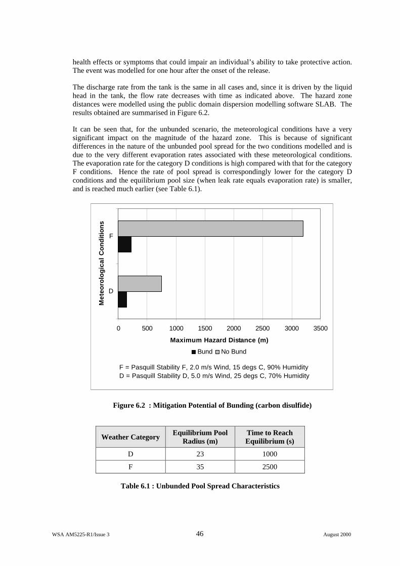
WSA AM5225-R1/Issue 3 46 August 2000
health effects or symptoms that could impair an individual’s ability to take protective action. The event was modelled for one hour after the onset of the release.
The discharge rate from the tank is the same in all cases and, since it is driven by the liquid head in the tank, the flow rate decreases with time as indicated above. The hazard zone distances were modelled using the public domain dispersion modelling software SLAB. The results obtained are summarised in Figure 6.2.
It can be seen that, for the unbunded scenario, the meteorological conditions have a very significant impact on the magnitude of the hazard zone. This is because of significant differences in the nature of the unbunded pool spread for the two conditions modelled and is due to the very different evaporation rates associated with these meteorological conditions. The evaporation rate for the category D conditions is high compared with that for the category F conditions. Hence the rate of pool spread is correspondingly lower for the category D conditions and the equilibrium pool size (when leak rate equals evaporation rate) is smaller, and is reached much earlier (see Table 6.1).
0 500 1000 1500 2000 2500 3000 3500
D
F
Met
eoro
log
ical
Co
nd
itio
ns
Maximum Hazard Distance (m)
Bund No Bund
F = Pasquill Stability F, 2.0 m/s Wind, 15 degs C, 90% HumidityD = Pasquill Stability D, 5.0 m/s Wind, 25 degs C, 70% Humidity
Figure 6.2 : Mitigation Potential of Bunding (carbon disulfide)
Weather Category Equilibrium Pool Radius (m)
Time to Reach Equilibrium (s)
D 23 1000
F 35 2500
Table 6.1 : Unbunded Pool Spread Characteristics
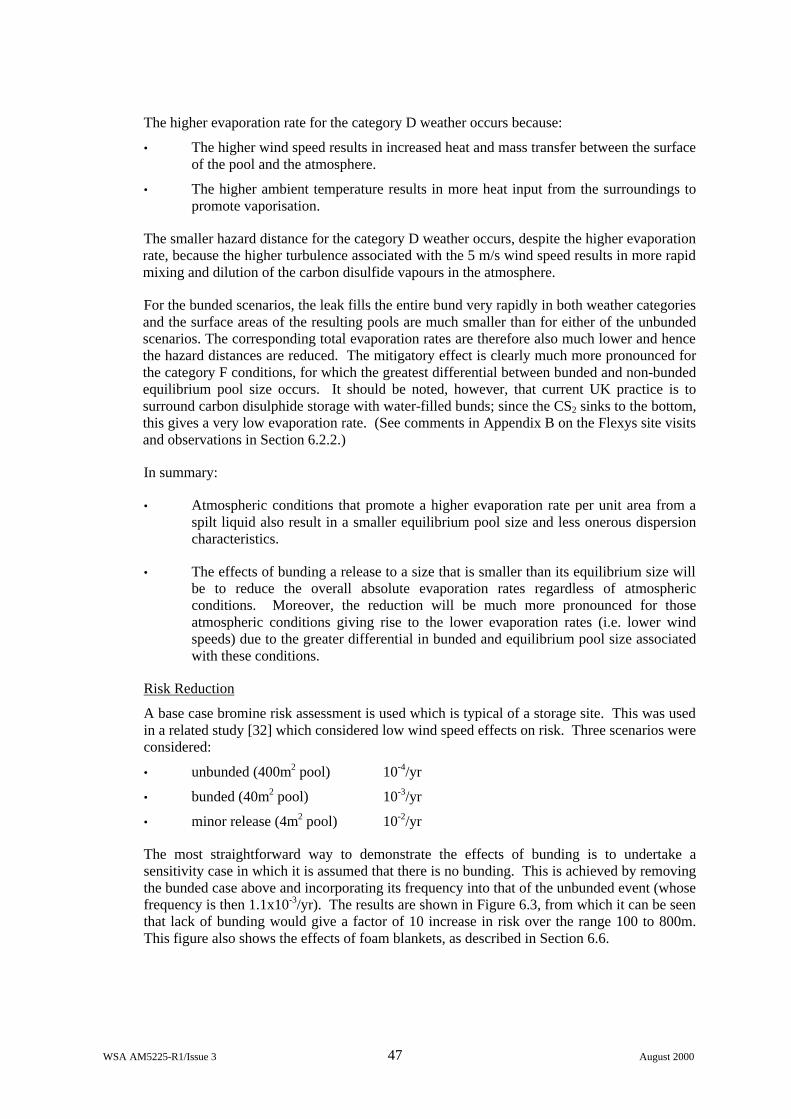
WSA AM5225-R1/Issue 3 47 August 2000
The higher evaporation rate for the category D weather occurs because:
• The higher wind speed results in increased heat and mass transfer between the surface of the pool and the atmosphere.
• The higher ambient temperature results in more heat input from the surroundings to promote vaporisation.
The smaller hazard distance for the category D weather occurs, despite the higher evaporation rate, because the higher turbulence associated with the 5 m/s wind speed results in more rapid mixing and dilution of the carbon disulfide vapours in the atmosphere.
For the bunded scenarios, the leak fills the entire bund very rapidly in both weather categories and the surface areas of the resulting pools are much smaller than for either of the unbunded scenarios. The corresponding total evaporation rates are therefore also much lower and hence the hazard distances are reduced. The mitigatory effect is clearly much more pronounced for the category F conditions, for which the greatest differential between bunded and non-bunded equilibrium pool size occurs. It should be noted, however, that current UK practice is to surround carbon disulphide storage with water-filled bunds; since the CS2 sinks to the bottom, this gives a very low evaporation rate. (See comments in Appendix B on the Flexys site visits and observations in Section 6.2.2.)
In summary:
• Atmospheric conditions that promote a higher evaporation rate per unit area from a spilt liquid also result in a smaller equilibrium pool size and less onerous dispersion characteristics.
• The effects of bunding a release to a size that is smaller than its equilibrium size will be to reduce the overall absolute evaporation rates regardless of atmospheric conditions. Moreover, the reduction will be much more pronounced for those atmospheric conditions giving rise to the lower evaporation rates (i.e. lower wind speeds) due to the greater differential in bunded and equilibrium pool size associated with these conditions.
Risk Reduction
A base case bromine risk assessment is used which is typical of a storage site. This was used in a related study [32] which considered low wind speed effects on risk. Three scenarios were considered:
• unbunded (400m2 pool) 10-4/yr
• bunded (40m2 pool) 10-3/yr
• minor release (4m2 pool) 10-2/yr
The most straightforward way to demonstrate the effects of bunding is to undertake a sensitivity case in which it is assumed that there is no bunding. This is achieved by removing the bunded case above and incorporating its frequency into that of the unbunded event (whose frequency is then 1.1x10⁻³/yr). The results are shown in Figure 6.3, from which it can be seen that lack of bunding would give a factor of 10 increase in risk over the range 100 to 800m. This figure also shows the effects of foam blankets, as described in Section 6.6.
WSA AM5225-R1/Issue 3 48 August 2000
1.0E-09
1.0E-08
1.0E-07
1.0E-06
1.0E-05
1.0E-04
1.0E-03
0 100 200 300 400 500 600 700 800 900 1000
Distance from installation (metres)
Indi
vidu
al r
isk
of r
ecei
ving
a d
ange
rous
dos
e or
wor
se fo
r a
res
iden
tial p
opul
atio
n (p
er y
ear)
Bromine base case
Unbunded case
Foam blanket case
Figure 6.3 Sensitivity of bromine risk assessment to bund and foam blanket effects
6.3 ADDITIONAL SKINS
6.3.1 Consequence mitigation
The presence of an additional skin will modify the mode of release from a vessel or pipe. Very small leaks could be detected and hence contained. Larger leaks, such as full bore guillotine ruptures, are likely to result also in failure of the outer skin, thus hardly affecting the release rate. It will therefore be necessary to assess the nature of the release event carefully to ascertain how, if at all, the source terms should be modified.
Flange guards are included within this section, although they are rather different from a complete additional skin, in that they will deflect rather than contain any release. The main effect from a consequence viewpoint is that the escalation potential of the event may be reduced, for example by preventing an oil mist spraying onto adjacent hot surfaces (see Section 4.8.3). A further effect is to cause rain-out and pool formation from flashing releases which would otherwise be completely airborne.
6.3.2 Frequency effects
If there is an additional skin, it is likely that the vessel or pipework in question would be constructed to a higher integrity than the equivalent item with a single skin. This suggests that the frequencies of initiating events will be reduced relative to those which apply to industry standard pipes and vessels, although it should be noted that there is likely to be considerably less failure data for such vessels etc. on which to base improved frequency estimates.
A further issue in relation to the release frequency relates to the possibility of detection, since many systems of this type would be designed with detectors located within the annular gap.
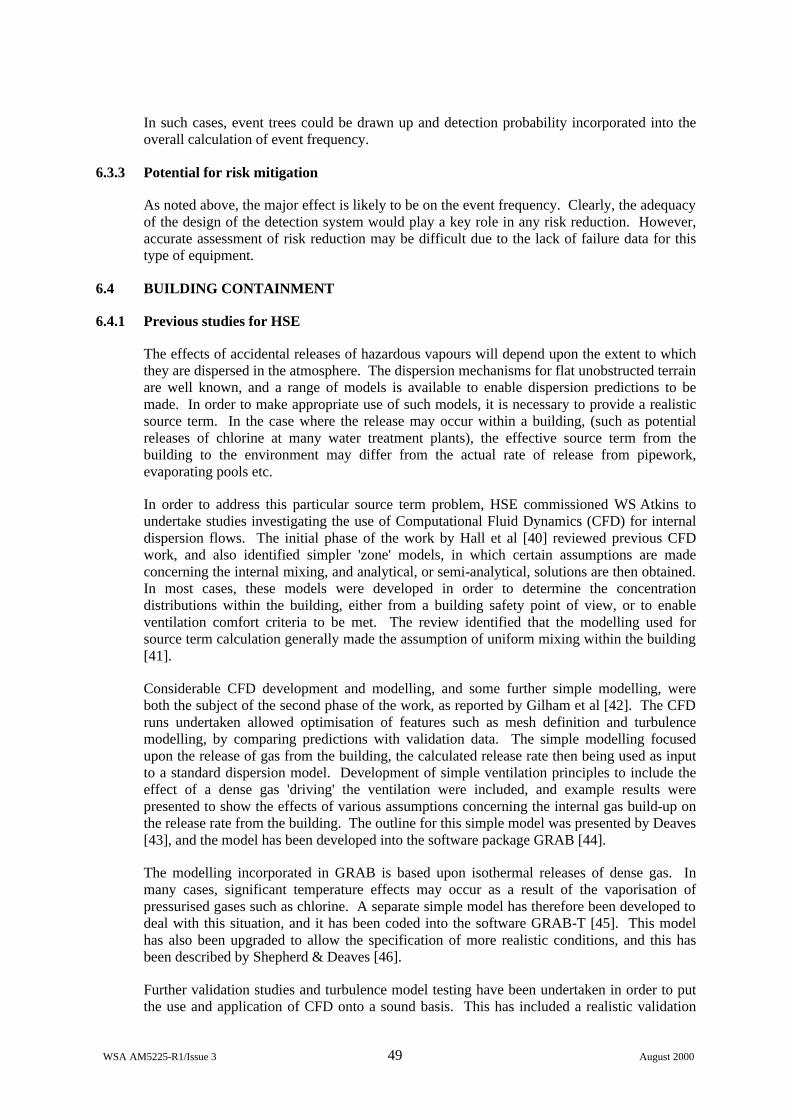
WSA AM5225-R1/Issue 3 49 August 2000
In such cases, event trees could be drawn up and detection probability incorporated into the overall calculation of event frequency.
6.3.3 Potential for risk mitigation
As noted above, the major effect is likely to be on the event frequency. Clearly, the adequacy of the design of the detection system would play a key role in any risk reduction. However, accurate assessment of risk reduction may be difficult due to the lack of failure data for this type of equipment.
6.4 BUILDING CONTAINMENT
6.4.1 Previous studies for HSE
The effects of accidental releases of hazardous vapours will depend upon the extent to which they are dispersed in the atmosphere. The dispersion mechanisms for flat unobstructed terrain are well known, and a range of models is available to enable dispersion predictions to be made. In order to make appropriate use of such models, it is necessary to provide a realistic source term. In the case where the release may occur within a building, (such as potential releases of chlorine at many water treatment plants), the effective source term from the building to the environment may differ from the actual rate of release from pipework, evaporating pools etc.
In order to address this particular source term problem, HSE commissioned WS Atkins to undertake studies investigating the use of Computational Fluid Dynamics (CFD) for internal dispersion flows. The initial phase of the work by Hall et al [40] reviewed previous CFD work, and also identified simpler 'zone' models, in which certain assumptions are made concerning the internal mixing, and analytical, or semi-analytical, solutions are then obtained. In most cases, these models were developed in order to determine the concentration distributions within the building, either from a building safety point of view, or to enable ventilation comfort criteria to be met. The review identified that the modelling used for source term calculation generally made the assumption of uniform mixing within the building [41].
Considerable CFD development and modelling, and some further simple modelling, were both the subject of the second phase of the work, as reported by Gilham et al [42]. The CFD runs undertaken allowed optimisation of features such as mesh definition and turbulence modelling, by comparing predictions with validation data. The simple modelling focused upon the release of gas from the building, the calculated release rate then being used as input to a standard dispersion model. Development of simple ventilation principles to include the effect of a dense gas 'driving' the ventilation were included, and example results were presented to show the effects of various assumptions concerning the internal gas build-up on the release rate from the building. The outline for this simple model was presented by Deaves [43], and the model has been developed into the software package GRAB [44].
The modelling incorporated in GRAB is based upon isothermal releases of dense gas. In many cases, significant temperature effects may occur as a result of the vaporisation of pressurised gases such as chlorine. A separate simple model has therefore been developed to deal with this situation, and it has been coded into the software GRAB-T [45]. This model has also been upgraded to allow the specification of more realistic conditions, and this has been described by Shepherd & Deaves [46].
Further validation studies and turbulence model testing have been undertaken in order to put the use and application of CFD onto a sound basis. This has included a realistic validation

WSA AM5225-R1/Issue 3 50 August 2000
study [47], in which dense jet releases inside buildings were modelled, and a study on the potential for using Reynolds Stress turbulence modelling [48] for both internal and external dispersion calculations. A final study [49] drew together the key results from all these studies to determine the sensitivity of QRA to the inclusion of building containment effects, and to develop a methodology by which such effects could be incorporated into QRAs. This study enabled comparisons to be made between CFD results and those from simple models. It also provided guidance on the best way of incorporating building containment effects.
6.4.2 Available modelling techniques
In general, the degree of mitigation provided by a building will be determined by both the ventilation characteristics of the building and the nature of the release. Where a building is being used for secondary containment, it is assumed that there is little ventilation, so that the extent of mixing will principally be driven by the nature of the release. The location and characteristics of any openings in the building, adventitious or otherwise will then determine the release rate from the building. Hence, in these circumstances the degree of mitigation provided by the building will be driven largely by the source itself, and this may exhibit complex fluid dynamic and thermodynamic behaviour. Moreover, in an industrial situation, the building into which the release occurs is likely to have a complex geometry, typically including tanks, vessels and pipework.
CFD
In principle, all of the above features can be incorporated within a CFD model, as discussed in Section 6.4.1. CFD modelling of building mitigation has been investigated by Gilham et al [50] using the commercial CFD code STAR-CD. This study concentrated on releases into well sealed buildings of materials that form denser than air vapours. This demonstrated that the use of CFD techniques can give good predictions of contaminant release rates from buildings. For both jet and evaporating pool releases, good correlation with experimental data was achieved for concentrations, although the room temperatures were generally under-predicted.
It was also found that the results were highly sensitive to the modelling details, and that considerable care is required when using these techniques to ensure that the modelling accurately reflects the physics of the situation. In particular, care is needed in defining the leak source conditions, both fluid dynamically and thermodynamically, and in modelling the near-wall flow and heat transfer. Furthermore, the use of CFD techniques is still very resource-intensive, and is therefore likely to be too costly for routine practical application within a risk assessment framework. It should also be noted that any additional accuracy (over the use of simpler zone models) provided by the use of CFD modelling is likely to be offset by other uncertainties normally associated with the QRA procedure.
GRAB and GRAB-T
An alternative to CFD modelling is to make gross simplifications and assumptions to enable a simpler 'zone' model to be developed. For vapour releases, it may be assumed that the process is isothermal, whereas for flashing liquid releases the thermodynamic effects are important. Zone model type calculation methodologies for the release rates of pollutants from buildings have been developed for isothermal releases under the GRAB (Gas Release Attenuation by Buildings) project and for non-isothermal releases under the GRAB-T projects [51].
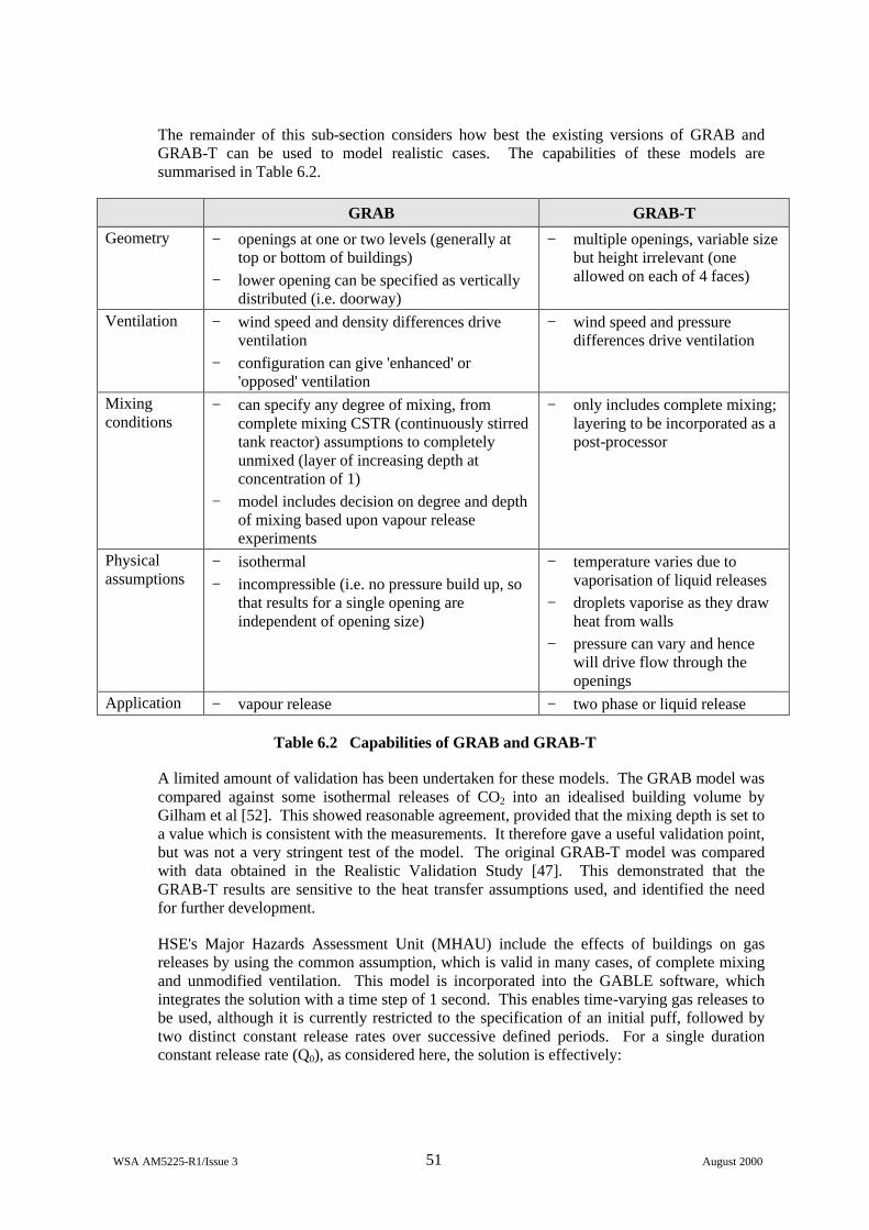
WSA AM5225-R1/Issue 3 51 August 2000
The remainder of this sub-section considers how best the existing versions of GRAB and GRAB-T can be used to model realistic cases. The capabilities of these models are summarised in Table 6.2.
GRAB GRAB-T
Geometry − openings at one or two levels (generally at top or bottom of buildings)
− lower opening can be specified as vertically distributed (i.e. doorway)
− multiple openings, variable size but height irrelevant (one allowed on each of 4 faces)
Ventilation − wind speed and density differences drive ventilation
− configuration can give 'enhanced' or 'opposed' ventilation
− wind speed and pressure differences drive ventilation
Mixing conditions
− can specify any degree of mixing, from complete mixing CSTR (continuously stirred tank reactor) assumptions to completely unmixed (layer of increasing depth at concentration of 1)
− model includes decision on degree and depth of mixing based upon vapour release experiments
− only includes complete mixing; layering to be incorporated as a post-processor
Physical assumptions
− isothermal − incompressible (i.e. no pressure build up, so
that results for a single opening are independent of opening size)
− temperature varies due to vaporisation of liquid releases
− droplets vaporise as they draw heat from walls
− pressure can vary and hence will drive flow through the openings
Application − vapour release − two phase or liquid release
Table 6.2 Capabilities of GRAB and GRAB-T
A limited amount of validation has been undertaken for these models. The GRAB model was compared against some isothermal releases of CO2 into an idealised building volume by Gilham et al [52]. This showed reasonable agreement, provided that the mixing depth is set to a value which is consistent with the measurements. It therefore gave a useful validation point, but was not a very stringent test of the model. The original GRAB-T model was compared with data obtained in the Realistic Validation Study [47]. This demonstrated that the GRAB-T results are sensitive to the heat transfer assumptions used, and identified the need for further development.
HSE's Major Hazards Assessment Unit (MHAU) include the effects of buildings on gas releases by using the common assumption, which is valid in many cases, of complete mixing and unmodified ventilation. This model is incorporated into the GABLE software, which integrates the solution with a time step of 1 second. This enables time-varying gas releases to be used, although it is currently restricted to the specification of an initial puff, followed by two distinct constant release rates over successive defined periods. For a single duration constant release rate (Q0), as considered here, the solution is effectively:
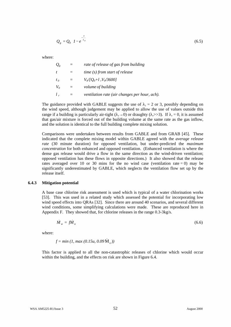
WSA AM5225-R1/Issue 3 52 August 2000
−=
−0e1QQ 0g
ττ
(6.5)
where:
Qg = rate of release of gas from building
τ = time (s) from start of release
τ0 = V0/[Q0+λrV0/3600]
V0 = volume of building
λr = ventilation rate (air changes per hour, ach).
The guidance provided with GABLE suggests the use of λr = 2 or 3, possibly depending on the wind speed, although judgement may be applied to allow the use of values outside this range if a building is particularly air-tight (λr→0) or draughty (λr>>3). If λr = 0, it is assumed that gas/air mixture is forced out of the building volume at the same rate as the gas inflow, and the solution is identical to the full building complete mixing solution.
Comparisons were undertaken between results from GABLE and from GRAB [45]. These indicated that the complete mixing model within GABLE agreed with the average release rate (30 minute duration) for opposed ventilation, but under-predicted the maximum concentration for both enhanced and opposed ventilation. (Enhanced ventilation is where the dense gas release would drive a flow in the same direction as the wind-driven ventilation; opposed ventilation has these flows in opposite directions.) It also showed that the release rates averaged over 10 or 30 mins for the no wind case (ventilation rate = 0) may be significantly underestimated by GABLE, which neglects the ventilation flow set up by the release itself.
6.4.3 Mitigation potential
A base case chlorine risk assessment is used which is typical of a water chlorination works [53]. This was used in a related study which assessed the potential for incorporating low wind speed effects into QRAs [32]. Since there are around 40 scenarios, and several different wind conditions, some simplifying calculations were made. These are reproduced here in Appendix F. They showed that, for chlorine releases in the range 0.3-3kg/s.
ow MfM && = (6.6)
where:
f = min (1, max (0.15u, 0.09 oM& ))
This factor is applied to all the non-catastrophic releases of chlorine which would occur within the building, and the effects on risk are shown in Figure 6.4.
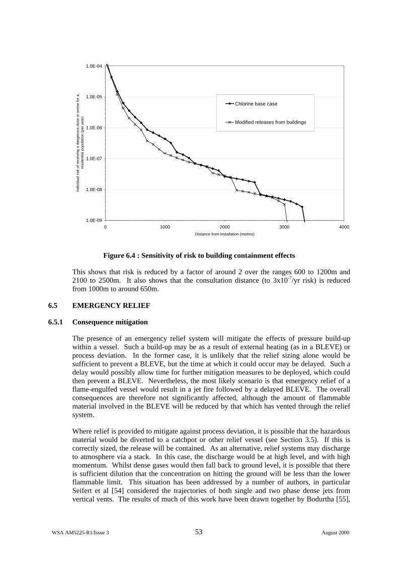
WSA AM5225-R1/Issue 3 53 August 2000
1.0E-09
1.0E-08
1.0E-07
1.0E-06
1.0E-05
1.0E-04
0 1000 2000 3000 4000
Distance from installation (metres)
Indi
vidu
al r
isk
of r
ecei
ving
a d
ange
rous
dos
e or
wor
se fo
r a
res
iden
tial p
opul
atio
n (p
er y
ear)
Chlorine base case
Modified releases from buildings
Figure 6.4 : Sensitivity of risk to building containment effects
This shows that risk is reduced by a factor of around 2 over the ranges 600 to 1200m and 2100 to 2500m. It also shows that the consultation distance (to 3x10⁻⁷/yr risk) is reduced from 1000m to around 650m.
6.5 EMERGENCY RELIEF
6.5.1 Consequence mitigation
The presence of an emergency relief system will mitigate the effects of pressure build-up within a vessel. Such a build-up may be as a result of external heating (as in a BLEVE) or process deviation. In the former case, it is unlikely that the relief sizing alone would be sufficient to prevent a BLEVE, but the time at which it could occur may be delayed. Such a delay would possibly allow time for further mitigation measures to be deployed, which could then prevent a BLEVE. Nevertheless, the most likely scenario is that emergency relief of a flame-engulfed vessel would result in a jet fire followed by a delayed BLEVE. The overall consequences are therefore not significantly affected, although the amount of flammable material involved in the BLEVE will be reduced by that which has vented through the relief system.
Where relief is provided to mitigate against process deviation, it is possible that the hazardous material would be diverted to a catchpot or other relief vessel (see Section 3.5). If this is correctly sized, the release will be contained. As an alternative, relief systems may discharge to atmosphere via a stack. In this case, the discharge would be at high level, and with high momentum. Whilst dense gases would then fall back to ground level, it is possible that there is sufficient dilution that the concentration on hitting the ground will be less than the lower flammable limit. This situation has been addressed by a number of authors, in particular Seifert et al [54] considered the trajectories of both single and two phase dense jets from vertical vents. The results of much of this work have been drawn together by Bodurtha [55],
WSA AM5225-R1/Issue 3 54 August 2000
who gives the following formula for setting the vent height to prevent flammable gas at ground level:
( )702.0
605.11Ls
35.1
s u10xAC/CD8.43
h-β
= (6.7)
where:
hs = stack height (m)
D = stack diameter (mm)
u = wind speed (m/s)
Cs = stack concentration (v/v)
CL = lower flammable limit of gas (v/v)
β = concentration fluctuation factor (2.5)
A1 = (SG2/(SG-1))1/3
SG = specific gravity of stack gas mixture (relative to air)
It is suggested that u = 1 m/s is used as a worst case, and the paper gives an example for the venting of 50 te/h of propane (SG=1.52, Cs/CL ~ 45) through a 10 inch vent, for which hs is 6.6 m.
If the vent flow could exceed the design intent, ground level concentrations could be calculated using a plume type model, such as AEROPLUME. When the plume has touched down, results are fed into the dense gas dispersion model HEGADAS. In such cases, the hazard ranges would be less than if the release were at ground level with low momentum.
6.5.2 Risk considerations
The relief of a fire-engulfed vessel may result in a delayed BLEVE event, as noted above. The calculation of risk would allow for such delays by considering the probability that the system is working correctly, and applying appropriate probabilities within an event tree. For emergency relief of a process vessel, the risk may be reduced, from that of vessel failure with total loss of inventory to that of a limited discharge at high level.
In both these cases, it is necessary to consider the design parameters of the relief systems in relation to the size of scenarios considered. This may allow some of the smaller events to be eliminated completely from the risk calculation, whilst reducing the effective frequency of some of the larger events. The reliability and availability of the scrubber system may also need to be considered when claiming credit for the mitigation potential of these systems.
Where emergency relief systems are used for toxic materials, it would generally be appropriate to incorporate some form of scrubbing, or possibly flaring to neutralise the effects of the discharge. An example where a flare system was inadequate (because it was disabled) was the Bhopal incident (Ref. I-30, Appendix C), which resulted in considerable loss of life.
For flammable materials, hazard ranges are not so great, and risks can be considerably reduced if any discharge allows the material to be detected below the lower flammable limit within a short distance. To this end, it may be possible to design systems such that the location, direction and momentum of the discharge result in the gas being diluted to below LFL before reaching ground level, as discussed in Siefert et al [54].
WSA AM5225-R1/Issue 3 55 August 2000
6.6 BARRIERS
6.6.1 Fences and shelterbelts
Solid fences result in additional dilution to vapour clouds as they drift offsite. This effect is greatest for dense gas releases at ground level. It is not routinely incorporated into dense gas dispersion models, although Webber et al [56] have demonstrated how a simple modification can be incorporated into DRIFT to allow for the enhanced dilution.
Shelterbelts (or 'greenbelts') can have a similar, but less marked, effect. In addition, certain species of tree or shrub can be used to absorb certain vapours, as described by Khan & Abassi [27], who describe examples of the attenuation of sulphur dioxide, hydrogen sulphide and ammonia by up to 40%.
One potential disadvantage of shelterbelts is the increased 'congestion' provided within flammable clouds which would exacerbate flame acceleration in vapour cloud explosions.
6.6.2 Spray barriers
Modes of action
The effectiveness of a water spray barrier as a means of mitigating the consequences of a release of a heavy gas may be assessed using a range of predictive models. Before choosing or applying any particular model it is useful to consider qualitatively the characteristic features of the gas dispersion in question and how these might influence the way in which a water spray barrier might act.
Water or steam curtains are employed to dilute a dispersing plume with air in order to reduce hazard distances following an accidental release. In view of the practicalities of deployment, in particular the inevitable delay in setting them up, such devices would only be appropriate in the event of relatively long duration releases. The natural dispersion of a flammable or toxic gas may be enhanced in this way by one or more of the following mechanisms:
• Mixing of entrained air with gas. This involves the entrainment of air in the water curtain which subsequently enters the gas plume such that the gas is mixed with the air inside the curtain.
• Momentum and turbulence. The water gives momentum and turbulence to the gas which improves the subsequent mixing with air outside the spray.
In addition to dispersion effects, spray curtains may use the following mechanisms to reduce the hazard posed by an accidental release:
• Physically carry gas in a preferred direction (e.g. upwards or away from ignition sources)
• Act as a gas barrier
• Absorb gases (e.g. HF)
• Heat gas to increase buoyancy (e.g. LNG) – although this may also act to increase vaporisation unless applied wholly to the already vaporised release
• Provide protection from thermal radiation
The modelling of the effects of water and steam sprays will therefore clearly depend upon the nature of the accidental release and dispersion mechanisms. The features of the calculation
WSA AM5225-R1/Issue 3 56 August 2000
models appropriate for heavy gas and soluble gas releases are discussed in the following sections.
Heavy-gas dispersion
The principal feature of heavy gas dispersion is the large lateral spread associated with gravitational effects compared with that of neutrally buoyant or passive dispersion. Although the rate of entrainment of air on the top surface of a heavy-gas plume is somewhat lower than that for a passive plume due to the suppression of turbulence by the density difference, this may be offset to some extent by the larger plan area through which entrainment occurs.
In particular, for a large instantaneous release, the large outward movement of the plume edges also causes air to be entrained across these edges. Consequently, the additional mixing through the surfaces of the heavy gas plume may sometimes be sufficient to result in a shorter downwind distance to a given concentration than is the case for a passive plume. The gravitational effects rely on the density difference between the plume and the ambient air.
A water spray barrier acts to enhance the rate of dilution in the plume in order to enhance the downwind dispersion and hence reduce hazard ranges. However, for a heavy-gas plume, the action of a water spray barrier is also to reduce the density difference between the plume and the ambient air, and hence also to reduce the gravitational effects. Thus the rate of dilution due to gravitational effects will reduce and may to some extent counteract the enhanced rate of dilution at the barrier. There is therefore a possibility that the suppression of gravitational effects may to some degree offset the enhanced dilution induced at the spray barrier. However, the overall effect would still be expected to reduce the hazard range, and hence risk, compared with the dispersion that would occur without the action of the water spray.
Soluble gases
Water spray curtains may be used to absorb gases that are soluble in water such that the concentration of the gas is much reduced downwind of the water curtain. The effectiveness of the absorption process depends upon:
• water flow rate
• water drop size
• gas solubility
Fthenakis et al [57, 58, 59] have developed models for evaluating mass transfer induced by water sprays. Trends predicted by these models indicated increased removal efficiency (for Hydrogen Fluoride) with decreasing water drop size and decreasing wind speed. Modelling results also suggested that sprays used in upflow are more effective than those used in downflow for the same water flow rate.
Experiments using Hydrogen Fluoride by Blewitt et al [60] and Schatz & Koopman [61] also concluded that removal efficiency increases with water drop size and that upflows are more efficient than downflows. A further key finding of these experiments was that the water to HF ratio is a key variable. The removal efficiency was observed to increase from around 10% to around 80% over the water to HF mass ratio range of approximately 5:1 to 60:1. These experiments also suggested that wind speed and relative humidity have negligible effects on removal efficiencies under the test conditions for both HF and Alkylation Unit Acid (AUA).
WSA AM5225-R1/Issue 3 57 August 2000
Mitigation Potential
The potential degree of mitigation provided by water sprays as a means of secondary containment has previously been investigated for hydrofluoric acid (HF) in the AIChE guidance document [6]. A 19.1 mm diameter breach from a tank having a capacity of 29 m3 was considered. The HF in the tank was assumed to contain 2% water by weight and the storage conditions were 1.4 bara and 15°C.
The hazard range associated with such a release was investigated for category F Pasquill stability conditions with a wind speed of 1 m/s, an ambient air temperature of 15oC and a 50% relative humidity. These are considered to be extremely onerous conditions with respect to dispersion distances. The hazard distance was defined as the distance to the Emergency Response Planning Guideline (ERPG-2) concentration of 20 ppm for HF. This is the maximum airborne concentration below which it is believed that nearly all individuals could be exposed for up to 1 hour without experiencing or developing irreversible or other serious health effects or symptoms that could impair their ability to take protective action.
Since the HF is being stored below its normal boiling point (BP = 19.5oC), it was assumed that no aerosols would be formed. All of the HF released would therefore form a liquid pool on the ground. The hazard ranges were modelled using the HGSYSTEM dispersion modelling software. It was assumed that the water spray curtain would be activated 1 minute after the initial release occurs and would provide a 86% removal efficiency. This is considered to be towards the high end of what can be achieved using water sprays.
The results of these studies indicated that the maximum hazard range for such a release could be reduced from 5,000 m to 750 m by the use of the water spray. This very significant reduction is due to the absorption effects, which are assumed to be such as to reduce the amount of HF to be dispersed by a factor of around 7. For other materials, which are diluted rather than absorbed, the effects will be rather less. It should be noted, however, that higher concentrations would be experienced at the early stages of release when the spray is being activated. This has implications for the accumulation of dose, or the potential for escape.
The LPG risk assessment used in [32] has been used here in order to determine the sensitivity of risk to the use of water sprays. In this case, the effect is considered purely from the viewpoint of enhanced dispersion, since LPG is not absorbed by the spray, and it is assumed that each of the non-catastrophic liquid and vapour releases has its dispersion enhanced by the inclusion of 12 m3/s of extra entrained air. The results are shown in Figure 6.5, which excludes BLEVE and catastrophic release effects for clarity, and shows only a very small effect close to the source.
These results demonstrate that adding extra dilution from a water spray will have a beneficial effect close to the source, which may be advantageous if there are likely to be ignition sources in this region. However, at greater distances the effects decay rapidly, resulting in little change to the risk.
Further considerations
It is noted that water sprays should be applied when there is vapour to be dispersed. Care should be taken to ensure that it is not applied inappropriately to vaporising pools, where the addition of further heat input from the water could enhance evaporation rates, resulting in larger vapour clouds and greater hazard ranges.

WSA AM5225-R1/Issue 3 58 August 2000
1.0E-07
1.0E-06
1.0E-05
1.0E-04
1.0E-03
0 20 40 60 80 100 120
Distance from installation (metres)
Indi
vidu
al r
isk
of r
ecei
ving
a d
ange
rous
dos
e or
wor
se fo
r a
res
iden
tial p
opul
atio
n (p
er y
ear)
LPG base case
Spray case
Figure 6.5 Sensitivity of LPG risk assessment (excluding BLEVE and catastrophic release events) to water spray effects
6.7 REMOVAL OF MATERIAL AT SOURCE
6.7.1 Absorbents
The overriding factor that influences the effectiveness of chemical absorption units in dealing with the consequences of major accident hazards is the original design basis for the unit. With some major accident hazard scenarios the sheer volume and concentration of gas or vapour released during the event might overload the equipment. In some cases, the concentration of gas or vapour leaving the absorption unit via a vent might exceed the design basis, resulting in employees and/or the public being exposed to concentrations such as to cause acute, or in some cases chronic, effects. In such an example one would conclude that the design basis had been incorrectly specified.
The first task therefore is to define accurately the design basis. If the chemical absorption equipment is required to deal with the consequences of major accident hazards then the design should be based on the worst credible event. Typical parameters to be defined include:
• the type of gas to be absorbed
• the quantity, flowrate and concentration of gas to be absorbed
• the temperature and pressure of the gas to be absorbed at the time of release
• the type of solvent required i.e. liquid to be employed to absorb the gas
• the degree of recovery required
WSA AM5225-R1/Issue 3 59 August 2000
6.7.2 Adsorbents
As for absorbents, the overriding factor that influences the effectiveness of the adsorption process in dealing with the consequences of major accident hazards is the design basis of the adsorption unit. In general the adsorption process would only be suitable for relatively small quantities or low concentrations of material. The effectiveness will also be dependent upon the type of adsorption process involved.
In order to determine the effectiveness of an adsorption unit it is therefore necessary to establish the design basis and then determine the extent by which this may be exceeded by the consequences of a major accident hazard.
6.8 BLANKETS OR COVERS
6.8.1 Effects
A blanket of foam or other material used to cover a liquid spill will reduce the evaporation rate and hence reduce the source term. This will result in a corresponding reduction in hazard range arising from dispersion of the vapours.
The use of such a system would usually also require the presence of a bund, or other additional secondary containment device such as a mobile boom, so that the foam or cover can be maintained in place over the spill. In these cases the calculation of the effect of the cover will take account of two principal factors:
• the length of time following the initial spill before the cover is applied
• the degree to which the evaporation rate is modified by the presence of the cover
6.8.2 Mitigation potential
The mitigation potential of the use of foam to cover an accidental release of n-pentane has previously been investigated [6]. A 50 mm diameter breach from a cylindrical tank having a radius of 4.3 m and a height of 6.5 m was modelled. The tank was assumed to be filled to 60% capacity and surrounded by a bund, of diameter 8.4 m and having a vertical wall height of 1.5 m, in which both the spill and the foam covering is contained.
The hazard distance associated with such a release was investigated for various meteorological conditions, both with and without a foam covering. The hazard distance was defined as the distance to a mean concentration of half the Lower Flammable Limit (LFL). For n-pentane, LFL is 1.4% v/v and hence the hazard distance is the distance to 0.7% v/v.
Two meteorological conditions were modelled as follows:
• Pasquill Stability F, 2.0 m/s Wind, 15 oC, 90% Relative Humidity
• Pasquill Stability D, 5.0 m/s Wind, 25 oC, 70% Relative Humidity
For the mitigated scenarios, the foam is assumed to be applied 15 minutes after the initial leak and a reduction of 50% in the vaporisation rate due to the presence of the foam was assumed. The event was modelled for one hour after the onset of the release.
The discharge rate from the tank is the same in all cases and, since it is driven by the liquid head in the tank, the flow rate decreases with time. The leak fills the bund very quickly and thereafter the pool radius remains fixed by the dimensions of the bund and is the same in all cases.
WSA AM5225-R1/Issue 3 60 August 2000
The results indicated that, for the category D conditions, the hazard zone did not extend beyond the boundaries of the bund even without the application of the foam, implying that the application of the foam has very little mitigation potential. For the category F conditions, the unmitigated release has a maximum hazard range of 15 m. On application of the foam blanket, the hazard range once again becomes confined to the bunded area.
The use of hollow plastic spheres (such as ping-pong balls) to cover a liquid spill in order to reduce evaporation has also been previously studied [62]. In a test involving a spill of liquid ammonia, the resulting pool surface was covered with 0.8 inch diameter polypropylene balls to a depth of one ball. However, when compared with an equivalent uncovered pool, no significant difference in the rate of ammonia vaporisation was observed. When the cover consisted of multiple layers of balls however, a reduction in vaporisation was achieved. On a practical note, the use and effectiveness of such a system will to a large degree depend upon environmental conditions. This is because such balls, being lightweight, can easily be blown by the wind and hence full coverage may not be achieved.
The potential for risk mitigation in this case is determined using the bromine example described in Section 6.2.3. In order to demonstrate the effects of a foam cover, the release rate is reduced by 50%. The results have been presented in Figure 6.3, where a reduction of a factor of around 500 is seen over the distance range 250 to 450m.
6.9 REDUCTION OF FIRE SIZE AND EFFECTS
6.9.1 Mechanisms
Where flammable liquid collects in a bund, any resultant pool fire will be limited in size compared with that of a spreading pool. However, unless there is adequate drainage, it is possible that the bunded fire would last longer, and hence result in greater thermal doses, even though the peak thermal flux may be reduced. Clearly there is a trade off between fire size and duration, although most pool fire models will take the exposure duration to personnel to be limited by an escape time to the nearest shelter.
Drainage is an important feature, and, if correctly designed, could have the effect of channelling flammable liquid away from sensitive areas. The most obvious way in which this will help is the sloping of regions beneath vessels storing flammables; if this is well designed and maintained, it could significantly reduce the probability of escalation to involve other vessels, or a BLEVE (for liquefied flammable gases). A further important case is the elimination of running pool fires which could spread to other parts of the site and cause the scale of the event to escalate. A particular example of this is the Heaven Hills distillery fire, as described in Appendix C (event reference I-08).
6.9.2 Mitigation potential
The reduction of pool size by bunding will reduce the size, and hence severity, of a pool fire. Hazard ranges for a gasoline pool fire covering 40m2 (bunded) or 400m2 (unbunded) have been determined, taking a threshold harm criterion of 1000 thermal dose units. These results have been determined for a wind speed of 5m/s, and using standard assumptions regarding escape speed. The results are presented in Table 6.3, which shows a factor of 2.5 on hazard range.
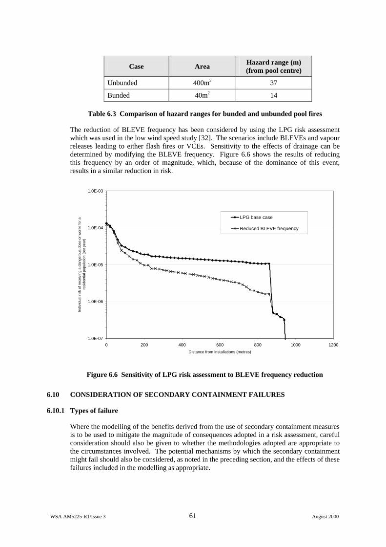
WSA AM5225-R1/Issue 3 61 August 2000
Case Area Hazard range (m) (from pool centre)
Unbunded 400m2 37
Bunded 40m2 14
Table 6.3 Comparison of hazard ranges for bunded and unbunded pool fires
The reduction of BLEVE frequency has been considered by using the LPG risk assessment which was used in the low wind speed study [32]. The scenarios include BLEVEs and vapour releases leading to either flash fires or VCEs. Sensitivity to the effects of drainage can be determined by modifying the BLEVE frequency. Figure 6.6 shows the results of reducing this frequency by an order of magnitude, which, because of the dominance of this event, results in a similar reduction in risk.
1.0E-07
1.0E-06
1.0E-05
1.0E-04
1.0E-03
0 200 400 600 800 1000 1200
Distance from installations (metres)
Indi
vidu
al r
isk
of r
ecei
ving
a d
ange
rous
dos
e or
wor
se fo
r a
res
iden
tial p
opul
atio
n (p
er y
ear)
LPG base case
Reduced BLEVE frequency
Figure 6.6 Sensitivity of LPG risk assessment to BLEVE frequency reduction
6.10 CONSIDERATION OF SECONDARY CONTAINMENT FAILURES
6.10.1 Types of failure
Where the modelling of the benefits derived from the use of secondary containment measures is to be used to mitigate the magnitude of consequences adopted in a risk assessment, careful consideration should also be given to whether the methodologies adopted are appropriate to the circumstances involved. The potential mechanisms by which the secondary containment might fail should also be considered, as noted in the preceding section, and the effects of these failures included in the modelling as appropriate.
WSA AM5225-R1/Issue 3 62 August 2000
Such containment failures may include:
• passive equipment integrity failures
• active equipment unavailability
The overall risk reduction potential of a secondary containment measure having a relatively low hazard reduction potential but a very high reliability may be much higher than that of an alternative system having a very high hazard reduction potential but a poor reliability.
6.10.2 Passive equipment integrity failure
Where the secondary containment measures employed are passive, their availabilities would be expected to be very high. However, consideration should be given to availability issues, and, in particular, the possibility that the secondary containment could become ineffective due to integrity failure. Such a loss of integrity may arise due to inherent failure of the containment or as a result of the release event itself.
Examples of inherent failures include:
• Corrosion of double skinned containment
• Buildings or enclosures which are not leak tight
Examples of failures due to release events include:
• Fluid loading on bund
• Physical damage to bund
• Collapse of bund due to thermal shock arising from contact with cryogenic liquid
• Overpressurisation of building
6.10.3 Active equipment unavailability
Where the secondary containment provisions incorporate active systems, any allowance for the mitigation afforded by these provisions should include consideration of the expected availability of the systems. Such active systems might include:
• Spray barrier
• Scrubber
The availability of these systems will be dependent on the exact configuration of equipment which may vary according to circumstance. The reliability of individual items of equipment should be obtained from site specific sources where available, or alternatively, derived from generic databases [63, 64].

WSA AM5225-R1/Issue 3 63 August 2000
7 CONCLUSIONS
7.1 CURRENT USE OF SECONDARY CONTAINMENT
The visits made to the five sites, reported in Appendix B and summarised in Section 4, have demonstrated a healthy awareness of secondary containment issues over a wide range of industrial installations. This has probably been brought about as a result of increased concern for the environment, since the greatest emphasis was on ensuring that potentially polluting materials cannot be inadvertently lost from the site.
On all sites, bunding was provided for vessels which stored sensitive materials. The discussions revealed a generally good awareness of the requirements and of the issues involved, and also highlighted operational problems such as bund drainage or overflow. Drainage issues were also a common feature of concern at the sites. In all cases, systems were in place to ensure that undesirable materials, including fire water run-off, would not be released from the site. On several of the sites, complex systems involving holding tanks, drainage sumps, and effluent treatment plant, were in place to ensure that no contaminated water reached local watercourses.
There was less consensus regarding other containment measures, with some, such as flange guards, preferred at some sites but rejected at others. Certain general issues did emerge, however, such as the desire to minimise pool evaporation (for example by the use of thermally insulating concrete, or coverings, of water or of foam) and the use of fire hoses to 'knock down' vapour clouds.
In summary, whilst secondary containment was taken seriously, and was implemented to a greater or lesser extent on each of the sites visited, the emphasis was clearly on ensuring that untreated liquid did not reach the environment. The more pertinent consideration for this study is the ability to reduce the scale of the development of any vapour cloud which forms as a result of a leak. The mitigation measures in such cases are less obvious than those used to protect against pollution. Although some measures are in place to reduce vapour cloud sizes and their effects, it is possible that a more structured approach, maybe based upon risk assessment calculations, could be used to identify further improvements.
7.2 SCOPE FOR RISK REDUCTION
The appropriate use of secondary containment measures should enable the off-site risk to be reduced, primarily by the effective reduction of release rates. This could be achieved, for example, with a foam blanket to reduce pool evaporation, or with a building to hold up the vapour before releasing it to atmosphere. Yet other measures, such as water sprays, may serve to dilute clouds or to add heat to make them buoyant (e.g. LNG/methane). In such cases, the scenario considered remains unchanged, but the reduction of effective release rate, or the enhanced dispersion, results in shorter hazard ranges.
Although the reduction of hazard range is the main driver in the reduction of risk, there may also be cases where the scenario is modified. An example is the use of flange guards, whose primary effect may be to prevent escalation, for instance by preventing released flammable material from impinging on a hot surface and igniting. In other cases, effective bund design and drainage provision may prevent the fire engulfment of a bulk flammable liquid vessel, thereby significantly reducing the probability of a BLEVE.
WSA AM5225-R1/Issue 3 64 August 2000
The calculations presented in Section 6 have demonstrated how risk results are affected by the consideration of secondary containment effects. The reductions in risk tend to be greatest for toxic materials, with reductions of up to an order of magnitude in some cases. The greatest scope is evident for volatile materials whose boiling point exceeds normal ambient temperature (e.g. bromine). In such cases, the possibility of vapour cloud formation can be almost eliminated by including measures which minimise vaporisation. For pressure liquefied gases, such as chlorine, it is much harder to reduce the vaporisation significantly. In such cases, the effects of small and moderate leaks can be ameliorated by use of containment buildings, but there is little that can be done to mitigate against the effects of large catastrophic releases.
7.3 POTENTIAL FOR IMPROVEMENT OF RISK ASSESSMENT METHODOLOGIES
The use of bunds is an obvious secondary containment measure which is applied over most sites which store or process significant quantities of hazardous materials. Their effects are relatively straightforward to include, and are currently considered within most risk assessments. Other measures are less obvious in their effect, and could usefully be included to ensure that realistic risk results are obtained. These include:
Buildings
The storage of toxic materials within buildings has a beneficial effect on off-site risk, as shown in the calculations in Section 6.4. Individual building configurations could be considered using the programs GRAB and GRAB-T. Alternatively, it would be possible to extend the calculations presented in Appendix F to give a range of simple formulae for the effective reduction in release rate from the building. The effect could be more realistically modelled by taking a transient release rate as input to a dispersion model, and any further calculations could be used to provide output in this form.
Bunds
Although the effects of bunds are considered routinely, certain additional features which have emerged from this study could be included to render the results more realistic. The first concerns bund drainage, since the bund effectiveness may be reduced if drainage pathways are available. Some assessment of the likelihood of this scenario could be made and, if necessary, further consequence modelling (such as escalation due to spread of fire) undertaken. A more positive feature which could also be considered is the potential for application of foam blankets, or other methods of reducing vaporisation.
The use of sumps in bunds, bund sub-divisions etc varies considerably between sites. Since these features could have a major effect on release rates, it would be appropriate to consider them when undertaking safety cases or risk assessments.
Barriers
Many sites will include fences and other features which, whilst not specifically so designed, would act to enhance dispersion. Although the significant effects are generally confined to the immediate lee of such features, they may be relevant if they enable flammable clouds to be diluted below LFL at locations which contain ignition sources. The effects of shelterbelts could also be considered, especially for toxic releases. An alternative form of barrier is the water or steam spray. Where fixed systems are supplied, their effects should be included, and there may be some scope for improving or simplifying the calculation techniques. Several sites referred to the use of fire fighting sprays to 'knock-down' vapour clouds. Some research into the effectiveness of this procedure, and development of simple calculation methodologies, would be useful.
WSA AM5225-R1/Issue 3 65 August 2000
Maximum pool areas for unconfined pods
The worst case event for hazards involving volatile toxic or flammable liquids is generally a major loss of containment leading to an unconfined pool, because either the release is not in a bunded area or the bund has failed or been overtopped. Current risk assessments often assume that such events lead to very large unconfined pools, which continue to evaporate for 30 minutes or more. However, the controlled drainage arrangements that are now common on many sites imply that the pool area and duration of evaporation from such spills may often be much less than the worse case assumptions would imply. A procedure for incorporating such considerations into risk assessments could have significant effects in reducing the predicted risk and help to focus on the most significant types of event.
7.4 GENERAL RECOMMENDATIONS
Since it has been shown that secondary containment can have a significant effect on risk, the potential for its provision should be considered systematically at each major hazard site. The following factors should be taken into account when determining the most appropriate application of secondary containment:
a) Nature and compatibility of materials
b) Nature of risks, including potential for escalation
c) Drainage and water reactivity issues
d) Whether fixed plant should be installed or mobile equipment deployed
e) Potential for reduction in risk
7.5 RECOMMENDATIONS FOR FURTHER WORK
Although this report has provided a broad overview of the current usage and effectiveness of secondary containment, there is clearly scope for obtaining a greater understanding in some areas. Examples of these are given below, with brief comments on the likely scope of any further studies.
a) Building containment
A range of representative conditions could be used within GRAB and GRAB-T, and look-up tables or simple algorithms provided for ease of application.
b) Bunding for special materials
For highly volatile liquids, or materials which react strongly with water, guidelines could be produced on the appropriate design of bunding, and also on the calculation of the source term in the presence of water.
c) Bund covers
A more detailed review could be undertaken to determine the range of types of such covers (foam/balls etc) and their effectiveness.
d) Bund overtopping
Whilst there are some correlations which can be used, most are for specific failure scenarios and simple bund wall shapes. It may be possible to improve and generalise these correlations by using CFD to model a wider range of scenarios and more complex bund wall shapes.
WSA AM5225-R1/Issue 3 66 August 2000
e) Pool sizes on real sites
The spreading of unbunded liquid pools will in practice be limited by the presence of kerbing, drainage and porosity. It would be possible to undertake a survey of a range of industrial sites which, together with flow modelling, could be used to assess likely maximum pool sizes and to develop a suitable methodology for use in safety cases and QRAs.
f) Vapour cloud 'knock-down'
The use of fire hoses or monitors to knock down vapour clouds seems to be fairly widespread. CFD could be applied to this type of situation in order to provide estimates of the effectiveness of this technique.
g) Disposal of dense vent gases
Vent stacks will normally be designed to ensure that gas concentrations are reduced to safe levels by the time they return to ground level. Where this is not possible (e.g. for a toxic material) or the design flow rate is exceeded, safe levels may be exceeded, and some further dispersion modelling will be necessary after the material returns to ground level. Some modelling of this situation could be undertaken to enable a method to be developed for estimating the characteristics of the source for subsequent dispersion modelling.
h) Failure rates of active systems
Since some of the systems described need to be deployed or activated at the time of the incident, the risk reduction will depend on their reliability and availability. A survey could be undertaken to collate failure rate data for a range of important active secondary containment systems.
i) Pipe bridge safety
Although pipework is vulnerable on pipebridges, little evidence was seen of secondary containment at these locations. A review of pipe bridge incidents could be undertaken, and an assessment made of the potential for consequence reduction by the use of sleeving etc.
j) Fire water run-off
Most sites are well equipped to prevent polluted water from leaving the site untreated. However, it may be possible for flammables to enter sewers etc, with the potential for escalating fire across a site. A detailed review could be undertaken of existing drainage arrangements, and recommendations given for ensuring best practice.
k) Emergency planning
Where deployable secondary containment devices are used, their effectiveness should be considered in drawing up the on-site emergency plan. For example, it may be possible to give consideration to the efficiency of systems in place to deal with accidental or excessive releases of vent gases, (e.g. scrubbing) which will affect source terms, with implications for emergency planning. A risk-based methodology could be developed to allow the integration of these effects.
WSA AM5225-R1/Issue 3 67 August 2000
8 REFERENCES
1. 'A Guide to the Control of Major Accident Hazards Regulations 1999', HSE, L111.
2. Design of containment systems for the prevention of water pollution from industrial incidents, Construction Industry Research and Information Association (CIRIA), Report 164, 1997.
3. The Design of Bunds, D. S. Barnes, SRD/HSE R 500, March 1990.
4. Bund Overtopping – The consequences following catastrophic failure of large volume liquid storage vessels, Wilkinson A, SRD/HSE R530, October 1991.
5. Guidelines for vapour release mitigation, Center for Chemical Process Safety (CCPS), American Institute of Chemical Engineers (AIChE), 1988.
6. Guidelines for Post Release Mitigation Technology in the Chemical Process Industry, Center for Chemical Process Safety (CCPS), American Institute of Chemical Engineers (AIChE), 1997.
7. HSE, HS(R)21 Rev 'A Guide to the Control of Industrial Major Accident Hazards Regulations 1984', HSE.
8. The Highly Flammable Liquids and Liquefied Petroleum Gases Regulations 1972, SI 1972/917 HMSO 1972 ISBN 0 11 020917 6.
9. Planning (Hazardous Substances) Regulations, 1992. [Updated by 'The Planning (Control of Major Accident Hazards) Regulation, 1999, SI 1999/981.]
10. HSE, 'HS(G)50 The storage of flammable liquids in fixed tanks (up to 1000 cu. m in total capacity)', ISBN 0 11 885532 8, 1990. [Note - Replaced in 1998 by HS(G)51 (for less than 1000 litres) and HS(G)176]
11. HSE, 'HS(G)52 The storage of flammable liquids in fixed tanks (exceeding 1000 cu. m in total capacity)', ISBN 0 11 885538 7, 1991. [Note - Replaced in 1998 by HS(G)51 (for less than 1000 litres) and HS(G)176].
12. Guidance on the bunding of bulk chemical storage vessels, Specialist Inspectors Report No. 39, HSE, 1993.
13. Manual of Firemanship, Home Office Fire Department, 1991.
14. HSE, 'HS(G)51 Storage of flammable liquids in containers', ISBN 0 7176 1471 9, 1998.
15. HSE, 'HS(G)176 The storage of flammable liquids in tanks', ISBN 0 7176 1470 0, 1998.
16. The Storage of Highly Flammable Liquids, HSE, Guidance Note CS2, HMSO 1977. (Withdrawn).
17. Buckley & Weaver, Documentation and Analysis of Historical Spill Data to determine Hazardous Material Spill Prevention Research Priorities, EPA Contract 68-03-0317, Report PB-281-090/IGA, April 1978.
WSA AM5225-R1/Issue 3 68 August 2000
18. Institute of Petroleum, 'Refining safety code', Part 3 of Model Code of Safe Practice in the Petroleum Industry, 3rd Edition, ISBN 0 471 261963 3, 1981.
19. Standard for the Production, Storage and Handling of Liquefied Natural Gas. National Fire Protection Association No. 59A, 1985. (Latest 1996).
20. LNG Storage Safety Guidance, IGE/SR/11, Institution of Gas Engineers, 1978.
21. British Compressed Gases Association. Bulk liquid oxygen storage at production sites. CP20 1996 Rev.1.
22. Standard for Bulk Oxygen Systems at Consumer Sites, National Fire Protection Association No. 50, 1985.
23. Chemical Industry Association 1975 Code of Practice for Large-Scale storage of fully refrigerated anhydrous ammonia in the United Kingdom. (2nd Edition June 1997).
24. Guide for pressure-relieving and depressurising systems, API recommended practice 521, 2nd Edition, American Petroleum Institute, 1982. (4th Edition, 1997).
25. American Society of Mechanical Engineers, Boiler and Pressure Vessel Code, Section VIII, 1974. (Latest edition 1998).
26. Design and sizing of knock-out drums / catchtanks for reactor emergency relief, Grossel S, Plant / Oper. Prog. 5 (3), 129, 1986.
27. Khan F. I. & Abassi S.A., Cushioning the impact of toxic releases from runaway industrial accidents with greenbelts, Journal of Loss Prevention, Volume 13, pp109-124, 2000.
28. Perry R.H. and Green D. Perry's Chemical Engineer' Handbook, 6th Edition, Published by McGraw-Hill, 1984.
29. Treybal R.E. Mass Transfer Operations, 3rd Edition, Published by McGraw-Hill, 1988.
30. Aqueous Foams for Vapor Mitigation – Practical Considerations, Norman and DiMaio, 6th International Symposium “Loss Prevention and Safety Promotion in the Process Industries”, Norwegian Society of Chartered Engineers, Oslo June 19-22 1989.
31. Lees, F.P., 'Loss prevention in the process industries', Butterworth-Heinemann, Second Edition, 1996.
32. Lines, I.G., Daycock, J.H. & Deaves, D.M. 'Guidelines for the inclusion of low wind speed conditions into risk assessments'. HSE Contract Research Report. Ref 276/2000, ISBN 0 7176 1812 9, Feb 2000.
33. Post, L. HGSYSTEM manual, 1994.
34. D M Webber, A users guide to GASP, SRD/HSE R496, 1989.
35. Greenspan H P and Young R E, J Fluid Mechanics, Vol 87, P179 (1978).
36. United States General Accounting Office, Liquefied Energy Gases Safety Report to the Congress of the United States, EMD-78-28, 1978.
WSA AM5225-R1/Issue 3 69 August 2000
37. Greenspan H P and Johanson A V, Studies in Applied Mathematics, Vol 64, P211, 1981.
38. Cuperus N J, Sixth International Conference on Liquified Natural Gas, Kyoto, Japan, Session II Paper 13, 1980.
39. Rouzsky et al, Second International Conference on Cryogenic Concrete, Amsterdam 1983.
40. Hall, R.C., Gallagher, P., Harris, M.T.G. and Deaves, D.M. HSE Contractor Report RSU 8000/005, 1995.
41. Brighton, P.W.M. 'Heavy gas dispersion from sources inside buildings or in their wakes', IChemE North Western Branch Symposium 'Refinement of Estimates of the Consequences of Heavy Toxic Vapour Releases', UMIST, Manchester, 8 January 1986.
42. Gilham, S., Ferguson, S. and Deaves, D.M. 'Dispersion of releases of hazardous materials within buildings - Phase II'. HSE Contractor Report. RSU 8000/012/1, 1996.
43. Deaves, D.M. 'Simple modelling of gas release from buildings'. HSE Contractor report RSU 8000/012/2. 1996
44. Spencer, H., & Deaves, D.M. 'Simple modelling of gas releases from buildings: Background to GRAB software'. HSE Contract Research Report 3521/R75.017/A, 1997a
45. Spencer, H., & Deaves, D.M. 'Simple modelling of gas releases from buildings: Background to GRAB software'. HSE Contract Research Report 3521/R75.017/B, 1997b
46. Shepherd, A.M., & Deaves, D.M., 'Gas release attenuations within buildings, effects of temperature GRAB-T'. HSE Contract Research Report Ref 3901/R72.046, Nov 1999.
47. Gillham, S., & Woodburn, P. 'Improved validation of source term modelling'. HSE report WSA/RSU8000/093, 1998.
48. Cowan, I.R., & Gallagher, P., 'Application of Reynolds stress modelling to gas build-up and external dispersion'. HSE Contractor Report RSU8000/096, 1998.
49. Lines, I.G., Luong, H.Y., Gilham, S., Spencer, H., & Deaves, D.M. 'Dispersion within buildings - Phase 3'. HSE Contract Research Report RSU8000/094, Feb 1999.
50. Gilham S, Deaves D M & Woodburn P, Mitigation of dense gas releases in buildings: validation of CFD modelling, Journal of Hazardous Materials, Vol 71, pp193-218, 2000.
51. Deaves D M, Gilham S & Spencer H, Mitigation of dense gas releases in buildings: use of simple models, Journal of Hazardous Materials, Vol 71, pp129-157, 2000.
52. Gillham, S., Deaves, D., Hoxey, R.P., Boon, C.R., & Mercer, A. 'Gas build-up within single building volume - comparison of measurements with both CFD and simple zone modelling', Journal of Hazardous Materials 53, 93-114, 1997.
53. Carter, D.A., Deaves, D.M., & Porter, S.R. 'Reducing the risks from major toxic gas hazards', Loss Prevention and Safety Promotion in the Process Industries, Volume 1, pp 679-689, Edited by J.J. Mewis, H.J. Pasman and E.E. De Rademaeker, Elsevier Science B.V, 1995.
54. Seifert, H., Giesbrecht, H., & Lenckel, W., 1984. 'Dispersion of heavy gases and single and two-phase vapours escaping from vertical outlets', Ger. Chem. Eng. Vol 7, pp126-137.
WSA AM5225-R1/Issue 3 70 August 2000
55. Bodurtha, F.T., 1988, 'Vent heights for emergency releases of heavy gases'. Plant/Operations Progress, Vol 7, no 2, pp122-126.
56. Webber, D.M., Jones, S.J., Martin, D., and Tickle, G.A., 'Modelling complex phenomena in gas dispersion', IChemE Symposium Series No. 139, Presented at 'Major Hazards Onshore and Offshore II', Manchester, 24-26 October, 1995.
57. Fthenakis V M, 1989, The feasibility of controlling unconfined releases of toxic gases by liquid spraying, Chemical Engineering Comm., 83: 173-189.
58. Fthenakis V M and Zakkay V, 1990, A Theoretical Study of Absorbption of Toxic Gases by Liquid Spraying, Journal of Loss Prevention in the Process Industries, 3: 197-206.
59. Fthenakis V M and Schatz K W, 1991, Numerical Simulations of Turbulent Flow Fields Caused by Spraying of Water on Large Releases of Hydrogen Fluoride, Fluid Dynamics of Sprays, FED-131 pp 37-44 ASME.
60. Blewitt, D.N., et al, 1987, Effectiveness of Water Sprays on Mitigating Anhydrous Hydrofluoric Acid Releases, Proceedings of the International Conference on Vapour Cloud Modelling, pp 155-171, AICE
61. Schatz K W and Koopman R P, 1990, Water Spray Mitigation of Hydrofluoric Acid Releases, Journal of Loss Prevention in the Process Industries, 3: 222-233.
62. Feind K, 1975, Reducing Vapour loss in Ammonia Tank Spills, Safety in Ammonia Plants and related Facilities Symposium, 17th Annual Proceedings, pp 114-118 New York, AIChE.
63. Guidelines for Process Equipment Reliability Data with Tables, Centre for Chemical Process Safety, AIChE, 1989.
64. IEEE Guide to the Collection and Presentation of Electrical, Electronic, Sensing Component and Mechanical Equipment Reliability Data, IEEE Standard 500, Corrected Edition, 1993.
65. Mackay D and Matsugu R, 1973, Evaporation rates of hydrocarbon spills on water and land, Canadian Journal of Chemical Engineering, 5: 434.
66. IChemE Hazardous Substances on spillage, Major Hazards Monograph, ed. D.A. Carter, 1995.
67. Dilwali K.M. & Mudan K.S., Dike design alternatives to reduce toxic vapor dispersion hazards, international conference on vapor cloud modelling, Nov 2-4 1987, CCPS.

WSA AM5225-R1/Issue 3 A-1 August 2000
APPENDIX A
NOMENCLATURE
ρ Liquid density
λ Aspect ratio of storage tank (R / H)
β concentration fluctuation factor
∆Hv Heat of vaporisation
∆T Temperature difference between bund floor and liquid
A Bund Height
A1 (SG2/(SG-1))1/3 where SG = specific gravity of stack gas mixture
Af Effective bund floor area
Aw Effective bund wall area
b Bund perimeter
Cl lower flammable limit of gas (v/v)
Cs stack concentration (v/v)
D stack diameter (mm)
H Height of liquid in tank
hs stack height (m)
k gas phase mass transfer coefficient
kf Heat transfer parameter for bund floor
kw Heat transfer parameter for bund wall
L Distance from tank wall to bund wall
M Molecular Weight
mf Boil off contribution from the bund floor
Ml Liquid outflow rate
mw Boil off contribution from the bund wall
N Moles lost to evaporation
Q Volume fraction of stored liquid spilled from bund
R Tank Radius
r pool radius
tr Time for pool to cover bund floor
u wind speed (m/s)
w Liquid regression rate
Y vapour mole fraction in equilibrium with liquid at the pool surface temperature
Yo vapour mole fraction present in the surroundings at ambient conditions
WSA AM5225-R1/Issue 3 B-1 August 2000
APPENDIX B
SITE VISIT REPORTS
CONTENTS
Hickson & Welch Ltd. B-2
Flexsys Rubber Chemicals Ltd. B-7
Solvay Interox B-13
Aventis CropScience UK Limited B-18
Site 5 B-24
WSA AM5225-R1/Issue 3 B-2 August 2000
Site: Hickson & Welch Ltd.
Date of Visit: 5th November 1999
1. Introduction
The Hickson & Welch (H&W) site at Castleford specialises in performing multI-stage chemical reactions such as chlorination, phosgenation, hydrogenation and nitration. They undertake contract manufacture of chemical intermediates for onward supply to various manufacturing industries. The site contains pilot plant areas, small scale production units and main reactor areas.
There are a number of separate manufacturing buildings of which some are dedicated facilities producing nitrotoluenes and downstream derivatives. The remaining equipment is multI-purpose for fine chemical manufacturing comprising:
• glass lined reactors
• stainless steel reactors
• reactors in other materials
• centrifuges with nitrogen inertion
• pressure / vacuum filters
• etc, etc
Some plant areas have local warehousing/ storage areas for in-process materials. A central warehouse facility of 10,000 m2 provides a raw material and final product stock area.
A major river flows through the site so that all the production areas (though not the main warehouse) are within 100m of the river. Part of the site is on an island formed by the river and a canal which is still in commercial use. The site subsoil is believed to be already contaminated due to previous industrial activity prior to the ownership of H&W.
2. Secondary Containment Provisions
A range of secondary containment measures are employed by H&W including:
• site design
• buildings
• fixed bunds
• mobile bunds
• mobile pallets
• absorbing materials
• mobile water spray
• double skinned vessels
WSA AM5225-R1/Issue 3 B-3 August 2000
Site Design
The main site rises slightly away from the river which will prevent spills and fire water from running from the process sector to the office area and eventually offsite. On the river side of the main site there is a continuous site kerb, approximately 300 mm high, formed of propriatory kerbing blocks set in a solid concrete foundation. The site can hold water at about 2,000 m3 per 10mm. The site also has four emergency tanks each of 250 m3 and one of 3000 m3.
Sumps
All spillages and rain water etc flow into site drain sumps (effluent pits). These are emptied using pumps to discharge the contents to a new on-site water treatment plant. All of these drains, from sump to water treatment plant, are overland on gantries. One of these pipes lies within a secondary containment system on the river bank.
There are many off-loading / loading areas for road tanker bulk materials. Offloading areas built or modified within the last few years slope towards a drain sump. In the case of Oleum 25, the off-loading area is also protected to keep the area dry. This is designed to reduce the impact of oleum/water mixing in the event of a spill. The new Oleum 65 offloading shed has a sump under the road tanker offloading area capable of holding all but the biggest spillage. Small spills would run to a secondary sump within the main sump to minimise the area of spill.
Buildings
As secondary containment, the Oleum storage buildings are watertight, but not air tight. The bunds are lined with a plastic coating (furane) to a height of approximately 4 feet.
Fixed Bunds
All Highly Flammable Liquid (HFL) storage vessels are bunded. Spillages of HFLs into bunds would be protected by foam blankets applied by the site fire brigade.
All strong acids are bunded, though one is not bunded to the full 110%. The bunding of the toxic stores is in progress with the majority completed.
There are two aerobic bio-treatment facilities for aqueous waste treatment. These are relatively new facilities and are substantially bunded. The offloading area for the bio-treatment plant is bunded and sloped.
In the case where storage tanks for water may be reassigned for the storage of other materials, then they are bunded.
The bunds around older plant and storage are constructed of brickwork. All new bunds are constructed of continuous, reinforced poured concrete. Bunds made of brick or concrete are of various heights and are designed to contain 110% of contents of the largest tank. However, there are a number of bunds which have low walls which would not contain a catastrophic failure if it created a surge wave.
Mobile Bunds
There is evidence of temporary bunding to prevent spillages or rain water entering specific areas using sand bags and temporary mobile socks.
WSA AM5225-R1/Issue 3 B-4 August 2000
Mobile Pallets
It was noted that there are drums of materials placed temporarily adjacent to process areas. To contain leaks, these drums are stacked on steel containment pallets one drum high. Plastic containment pallets are replacing the traditional steel pallets where corrosive materials are used.
Absorbing Materials
The plant has a chemical spill vehicle that contains all equipment necessary to contain small spills. Bicarbonate of soda and other suitable materials are used for absorbing small spills.
Mobile Water Spray
There are no fixed water spray systems or equipment for the dispersion of vapour clouds. However, where appropriate, dispersion can be attempted using the site fire brigade who are trained and equipped to provide water curtains.
Double Skinned Vessels
The phosgenation plant building itself is not enclosed, but the process equipment is double skinned as follows:
• The phosgene generation unit is double skinned and contains a number of process units. The space between the process units and the outer skin is air purged and monitored for leaks using gas detectors. These detectors indicate if there is a leak inside the phosgene generation equipment, but do not indicate which process unit is leaking.
• The process vessels which use phosgene are contained in a sealed concrete enclosure and this is swept with fresh air. The air exhaust from this enclosure to the scrubbers is monitored to determine whether the unit is leaking.
Covers
The drains in certain areas of the stored process area are covered with drain covers. These covers can be secured by a central locking mechanism, which pulls the cover down tight to seal it.
Although not designed or used as secondary containment, glass equipment is generally protected from potential impact damage by Perspex covers. Therefore, any leaks under pressure are prevented from spraying over adjacent plant and equipment.
3. Codes, Standards and Procedures
The main guidance on bunding that H&W use is HS(G)50 (recently superseded by HS(G)176). They also indicated that they use a number of company standards.
The plant uses a database to keep track of raw material and finished products. As part of this database a register of storage vessel contents is kept. In addition to details of the material stored, this site register also includes information on whether it is bunded and on the state of the bund.
WSA AM5225-R1/Issue 3 B-5 August 2000
All new storages for toxic liquids will be bunded, in line with recently introduced H&W policy.
The only exception is that storage vessels which contain materials that would solidify if a leak occurred might not be bunded, if it was judged not necessary following a risk assessment.
4. Incidents and Operational Experience
Incidents
H&W reported two incidents related to secondary containment.
• In the first, a bund drain valve was inadvertently left open. At the time maintenance work was going on in the bund which had led to a section of pipe being removed. A remote computer controlled operation then resulted in a leak when a valve was opened, by the computer, to charge material to the process. The resulting leak of methanol then flowed out of the bund through the open drain valve and created a spillage across a site roadway.
• The second incident involved a GRP storage tank containing waste nitric acid. The tank was suitable for use with this material but a drain line from the tank had been sealed with a steel blank protected by a rubber gasket. The rubber was not suitable for this duty and it failed, rapidly followed by the blank. Although the resulting leak was contained within the bund, the acid attacked a low level mild steel pipe connecting two adjacent dichloromethane storage tanks. The contents of these tanks were then also released. Fortunately, the tanks were not full at the time of the incident; but had all of the tanks involved in the incident been full, their capacity would have significantly exceeded the capacity of the bund, which was sized for 110 % of the capacity of a single tank. This would have led to the bund being over-topped and material being released to the site drainage network. However, given the containment of the site drainage system, even this secondary release would not have been released to the general environment. Following this incident, the site storage database was enhanced to consider the contents of adjacent tanks.
Operational Experience
One of the main operational problems encountered with the bunds is emptying rainwater out and then making sure that the drain valves are closed after use.
In general, bund pumps are sited outside the bunds. This is for ease of maintenance and in-situ cleaning / access. Bunds and sumps are emptied using drain valves, gulpers, air pumps and a small number of steam ejectors. There is a site procedure for bund emptying, with all bund drains, ejectors or pumps being locked off. The keys are held by nominated site managers and no bund may be drained without the appropriate paperwork being completed.
H&W indicated that, with hindsight, they would locate the phosgene vessel gas detectors more effectively to allow them to pinpoint exact leak locations more easily.
Other Issues
An issue that has arisen regarding the site database is a vessel that continually empties and fills during the process. The vessel had been categorised on the database as a storage vessel and hence should be bunded. However, had it been categorised as a process vessel then
WSA AM5225-R1/Issue 3 B-6 August 2000
bunding would not be required. The vessel is not bunded and the company feel that it is properly regarded as a process vessel, not a storage.
Between the main site and the island site, there is a bridge over the River Aire. This bridge is used to transport materials on and off the island site either by road transport or through pipelines. The bridge is of steel construction with delivery pipework over the top of the roadway. The pipework is not double skinned and there are no containment measures (guttering, trays etc) to prevent leakages spilling directly into the river. It was indicated that the bridge flexes during the traversing of large transport vehicles.
The site is small and compact and many storage tanks are tall with small footprints. It is felt that the bunding around these will not prevent spigot leaks falling outside the bund footprint. However, spigot flow is not considered by H&W to be a major cause for concern being very infrequent compared to other causes of leakage from the site storages.

WSA AM5225-R1/Issue 3 B-7 August 2000
Site: Flexsys Rubber Chemicals Ltd
Date of Visit: 10th January 2000
1. Introduction
The Flexsys Rubber Chemicals site at Ruabon is located on a steep hillside close to the River Dee and is surrounded by three villages. Local housing is sited at a minimum distance of around 150 m from the main process area.
The site was previously owned by Monsanto but became Flexsys Rubber Chemicals in 1995 under joint ownership of Solutia (Monsanto) and Akzo Nobel.
The major products of the company are rubber chemicals including accelerators, vulcanisation inhibitors and antidegradants. The production of these products involves the use of a wide range of raw materials, many of which are toxic or flammable, and are stored on site. These materials include:-
• Chlorine (around 60 tonnes on site)
• Ammonia (around 30 tonnes on site)
• Sodium Cyanide (around 60 tonnes on site)
• Phenol
• Aniline
• Acetone
The site has three separate areas:
• Main Process Area
• Waste Water Treatment Plant (WWTP)
• Warehouse
The main process area is located on a steep gradient and contains various process and storage facilities.
The WWTP is located on a separate site near the river, a short distance from the main process area. Water is taken from the River Dee for use on site and all effluents are treated in the WWTP before being returned to the Dee. Water is abstracted from the Dee downstream of the site by the local water companies to provide the potable supply to about two million consumers. Boreholes are used to test groundwater that is pumped to the WWTP. There are also old mine workings beneath the site which drain into the river. The WWTP is equipped with some underground storage capacity.
The warehouse occupies a separate site and is used to store finished products, many of which are combustible solids. Access to the warehouse from the main process area is possible via an underpass.
WSA AM5225-R1/Issue 3 B-8 August 2000
2. Secondary Containment Provisions
A range of secondary containment measures are employed by Flexsys including:
• site design
• buildings and enclosures
• fixed bunds, sumps and culverts
• relief systems and catchtanks
• fences and solid barriers
• flange guards
• mobile pallets
• absorbing materials
• foam
• water spray
Site Design
The site is sloped and has two separate drainage systems:-
• Weak Effluent
• Strong Effluent
All drainage flows to the WWTP for treatment and subsequent return to the River Dee. In addition, there are three specially constructed lagoons designed to accept surplus stormwater or firewater from the site. These lagoons may be drained using the weak effluent system and are lined with geomembranes.
The site roadways have been designed to contain and channel stormwater or firewater to the lagoons. Roadways are kerbed and provided with gratings and sub-surface channels.
The strong effluent drains are used to transfer process effluents to the WWTP and are all raised above ground. Leakages from these drains would therefore subsequently enter the weak effluent drainage system.
The warehouse is fitted with a smoke detection system. Although it is not bunded, the design of the site is such that any firewater run-off would be contained within the access underpass.
Buildings and Enclosures
Flexsys are currently constructing a dedicated offloading building for chlorine. This building will be commissioned shortly and is designed to house the supply tanker during offloading. It is provided with a ventilation system and caustic scrubber. The scrubber system has been designed to cope with up to 2 kg/s of chlorine (i.e. the chlorine generation rate associated with flashing from a guillotine break in the offloading hose). The building is also equipped with a sump that has been constructed from a special concrete with low conductivity to minimise heat transfer and subsequent evaporation. The building is also equipped with a chlorine detection system. The chlorine storage and vaporising facilities are not enclosed within a building. This decision was based on risk assessment studies that showed that road tanker offloading events dominate the risk.
WSA AM5225-R1/Issue 3 B-9 August 2000
The di-phenol guanidine (DPG) process was converted from a batch process to a continuous process in 1997. As part of this plant modification it was decided to enclose the process within a ventilated building. The extract from the building is stripped prior to discharge to atmosphere. The building has restricted entry, intercom and CCTV surveillance etc.
The chlorine storage tanks are provided with corrugated plastic weather protection. This is intended to shield the storage tanks from direct sunlight. It was noted however that the siting of the enclosure panels may help mitigate spigot flow if this were to occur, since the bund walls are located very close to the tanks.
Temporary tenting is used during maintenance operations involving cyclo-hexane mercaptan. Such tenting is vented through activated carbon drums.
Fixed Bunds, Sumps and Culverts
All flammables and toxics are bunded. All process units drain to local sumps that are sampled.
None of the bunds on site are fitted with drain valves, and all are emptied using steam ejectors. This eliminates the possibility of drain valves being left open following a drainage operation.
All offloading areas are provided with drainage and collection sumps or tanks. The tanks can be drained to the WWTP and mobile pumps would be used to extract spills from the offloading sumps. One of the main functions of these offloading sumps, which can hold the entire contents of a failed road tanker, is to prevent the danger of a running pool fire impacting on process areas. This is particularly important as many of the road tanker operations take place at the top of the steep gradient on which the site is situated.
The site effluents are pumped to the WWTP in pipework that runs in a concrete culvert. This culvert is equipped with sump pumps and dual high level interlocks that shutdown the transfer of effluents at high level.
The bund around the three chlorine storage tanks is segregated, with each tank having a separate section.
The two sodium cyanide storage tanks share a common bund. However, it was noted that these two tanks are in fact equalised and could be considered as effectively a single tank.
The carbon disulphide bund is water filled since this material is heavier than water and would be immiscible. The water is kept at a high level within the bund by an overflow to the weak effluent drainage system. It was not clear how small leaks into this bund would be detected.
The storage tanks for the following liquids are currently not bunded:
• Sodium Hydroxide
• Potassium Hydroxide
• Phthalic Anhydride (Molten)
In addition, tanks containing liquids which would solidify on release to atmosphere are not bunded.
WSA AM5225-R1/Issue 3 B-10 August 2000
Relief Systems and Catchtanks
The Sodium 2 – mercapto benzo thiazole (MBT) process is equipped with an emergency vent tank to allow the autoclaves to be vented if required. The extract from this process is treated prior to discharge to atmosphere to convert any hydrogen sulphide to sulphur dioxide.
The DPG process is equipped with a bursting disc / pressure relief valve arrangement and the vent system also incorporates a catchtank. There is a pressure alarm on high pressure in the vent system upstream of the relief valve.
The plant also incorporates double bursting disc vent arrangements on the liquid sulphur tank and the chlorine storage tanks.
Fences and Solid Barriers
A solid 6 – 7 foot high corrugated iron fence is installed around the top perimeter of the site, adjacent to the public road. This fence is primarily for site security, but the solid nature of its construction would also help mitigate the dispersion of dense gases onto the public land.
Similarly, the sodium cyanide tank bund was surrounded by a solid fence. This is primarily to prevent personnel access, but again may also help prevent spigot flow.
Flange Guards
Flange guards are used extensively on the distribution pipework for caustics. However, this is primarily for personnel protection.
Mobile Pallets
Some raw materials are supplied in drums as solids. These are not bunded in storage but once charged in the melter for process use, the drums are placed on mobile pallets.
Absorbing Materials
Sand bags and wood chips are available on site to cover spills.
Foam
The current site emergency plan involves the application of foam to any large liquid chlorine spills that occur.
Water Spray
Fixed and mobile monitors are provided on the site that could be used to generate water curtains as required.
3. Codes, Standards and Procedures
Flexsys generally adopt Monsanto guidelines for the design of secondary containment provisions.
Monsanto have a civil engineering design guide for bunds (C1040, Issue 3, 11/97). This standard specifies the requirements for bunds for above ground storage tanks and vessels, and for areas storing drums and small containers. The standard is mandatory for new and
WSA AM5225-R1/Issue 3 B-11 August 2000
modified bunds but does not apply retrospectively. The standard references HSE publications HS(G) 50 & 52 and SRD/HSE R500.
Monsanto also provide guidance on the design of reactor vent catchtanks (Guidance Note 11, 1983).
The site has also developed a release containment philosophy for hazardous materials. The notable features of this philosophy with respect to secondary containment are as follows:
• Secondary building containment will be used to contain toxic release sources where it is the industry’s established good practice.
• Processes with both a toxic and flammable hazard, which on release could lead to a flammable atmosphere, will not be enclosed in buildings.
• Direct over-pressure release to atmosphere from vessels containing material above its boiling point or with significant vapour pressure, that can lead to complaint from offsite personnel, should be protected by a re-seating pressure relief valve.
• For in-process vessels, secondary spill protection will be limited to that required for housekeeping, drip containment or maintenance purposes.
• Storage tanks containing flammables, with a flash point less than 32oC, will be bunded in accordance with HS(G)176. The bunding requirement for tanks containing other materials will be assessed for their environmental and safety impact in the event of a leak.
4. Incidents and Operational Experience
Incidents
Flexsys reported four incidents related to secondary containment:
• In 1984 an underground effluent pipe developed a leak which allowed Aniline to penetrate a mine adit from where it flowed into the River Dee. It was as a consequence of this incident that all strong effluent pipework was raised above ground. If such a leak were to occur again, the new drainage configuration would allow the spill to be collected by the weak effluent system and hence would still be discharged offsite via the WWTP.
• In 1995 a quantity of Hydrogen Sulphide was released from the MBT process. This process vents directly to atmosphere and hence, when process instrumentation failed, resulting in a high pressure deviation in the process, the hydrogen sulphide relief valve lifted as designed and a release via the vent stack occurred. The instrumentation on the process has since been upgraded.
• A storage tank containing a white spirit type solvent developed a leak. Although the tank was bunded, the bund had an annulus type of support for the tank. The annulus was filled with bitumen and rubble. The leak ran into the annulus and bypassed the bund by permeating through the annulus.
• A leak occurred in a chlorine transfer line due to corrosion. The leak was spotted by a passing worker who initiated an emergency shutdown. The chlorine transfer system has since been redesigned and vaporisers adjacent to the storage area are now used to
WSA AM5225-R1/Issue 3 B-12 August 2000
supply a gaseous transfer system. This system is equipped with a sensitive automatic shutdown system based upon accurate differential flow measurement across the transfer lines.
Operational Experience
The use of flange guards on the plant has been the subject of some consideration on plant recently due to the difficulties associated with accelerated corrosion of bolts within the flange guards. The need for the guards is under review due to the high integrity of spiral wound gaskets. However, the problem of bolt corrosion has been solved by the adoption of a new style of flange guard, which leaves the bolts exposed to the atmosphere. The new style guards are also less expensive than the old style guards.
It was noted that there is a procedure to ensure that drainage valves on the top road offloading area drain tank are closed while offloading is taking place.
Other Issues
When the chlorine vaporisers were installed, consideration was given to the provision of double skinned distribution pipework for the chlorine gas. This was rejected however due to the associated problems with inspection of the inner pipe and the possibility of moisture build up in the annulus. It was felt that the risks of chlorine releases from these pipes could be adequately managed using a leak detection system based upon automatic flow differential metering on the supply and take-off points. The supply pipelines from each vaporiser are separately monitored and isolatable. Isolation of the system is automatic on detection of flow differential.
It was noted that, although the anhydrous ammonia tank is bunded, the bund wall is not particularly high and is partly intended to prevent spilled flammables from running under the tank. Also, the tank is passively fire protected and clad with stainless steel. Again, this could be considered to be a secondary skin to the vessel but is primarily provided for fire protection.
It was mentioned that a site owned by the Flexsys parent company at Newport has storage facilities for PCl3. This reacts with water and the bunding issues for such a material were thought to be potentially of some interest.
WSA AM5225-R1/Issue 3 B-13 August 2000
Site: Solvay Interox
Date of Visit: 10th March 2000
1. Introduction
The Solvay Interox site occupies around 58 acres and is located adjacent to residential areas in Warrington. The principal products of the company are hydrogen peroxide and related chemicals, which have been produced on the Warrington site since the mid 1940’s. Formerly part of Interox, a joint company owned by Laporte Industries Limited and Solvay SA, the site has been wholly owned by Solvay since 1992.
There are three main processes carried out on site:
• Auto Oxidation (AO) 50,000 tonnes / year (hydrogen peroxide)
• Caprolactone (CAPA) 15,000 tonnes / year
• Persalts 60,000 tonnes / year
Hydrogen peroxide is used as a bleach in the pulp and paper, textiles and consumer products industries. It is distilled on site to various grades ranging from 35% to 87%. The Solvay site is the only UK manufacturer of hydrogen peroxide. The process involves an inventory of around 900 tonnes of solvent.
Caprolactone products are primarily used in the polyurethane and coating industries to improve the performance of plastic materials. Improved stiffness and colour uptake are two useful property enhancements that are utilised in surface coatings and such products as shoe stiffeners and orthopaedic splints.
Persalts products are used in the soap and detergent product industries.
The site is adjacent to both the Mersey Estuary and the Manchester Ship Canal. Fire water is abstracted from the Manchester Ship Canal and a consent dating from 1988 allows discharge of cooling water and effluent to the Mersey. Discharges currently run at around 600 tonnes / hour. A separate discharge consent exists for the discharge of process effluent to the Warrington North Sewage treatment works.
The caprolactone plant and AO process are authorised by the Environment Agency under Integrated Pollution Control (IPC) regulations.
The site has recently completed the installation of a comprehensive effluent monitoring and database system to provide continuous analysis, improved control and data to target areas for improvement.
The site is classified as Top Tier COMAH due to the production and storage of over 200 tonnes of oxidising agent on site.
2. Secondary Containment Provisions
An extensive environmental improvement programme was initiated in 1994. This involved considerable capital investment over a 5 year period. A formalised and structured
WSA AM5225-R1/Issue 3 B-14 August 2000
methodology was used to identify and prioritise areas for possible improvement. This resulted in over 80% of the capital investment programme being allocated to secondary containment provisions.
Many of the secondary containment provisions were retro fitted to existing plant, but some provisions were also introduced in the design of a new CAPA plant in 1997.
The following secondary containment methods are employed on the Solvay site :-
• site design and drainage
• fixed bunds
• buildings
• mobile booms
• cyclones
• bursting discs
• mobile pallets
• water spray
• covers and mobile devices
Site Design and Drainage
The site has an integrated drains system that serves process area spills, waste effluents, storm water, fire water and site spills. The main consideration behind the design of these systems is the problem associated with handling large volumes of normal process effluents, whilst maintaining a capability to contain possible spillages. There is also a relatively large storm water load due to the large plan area of the site.
The AO process is served by a dual stream drainage system. Process effluents and small process spills (collected in process area bunds) flow into a central Stainless Steel drainage channel via tundishes located at each drainage point. These flow through a central drainage channel to a collection pit via a tilt plate separator (TPS). These effluents are tested and adjusted for pH and then discharged to Sewer via an effluent scrubber.
Should the drainage rate from the process area bunds become excessive (e.g. during firewater conditions or extraction column dump), the tundishes are designed to overflow into a secondary (normally flooded) central 36 inch ceramic drainage system. This drain flows to a 100 m3 dump pit. This dump pit incorporates an underflow weir, but does not provide good settlement. The dump pit is emptied to either the effluent collection pit (via the TPS), or to the Ship Canal (via a penstock valve).
The caprolactone monomer plant employs collection and containment pits incorporating an oily water separator (OWS). Process effluents, mostly water soluble organics, are directed to the 50 m3 OWS. Effluent on the clean side of the OWS is analysed for total carbon and pH and then pumped to a 44 m3 neutralisation pit before discharge to Sewer. In the event of high Total Carbon or high pH, the OWS pump stops and overflow occurs to one of the two containment pits Process dumps and peracetic acid storage tank spills are collected in a
WSA AM5225-R1/Issue 3 B-15 August 2000
separate 60 m3 ‘happenings’ pit. The happenings pit may be discharged to either the OWS or the containment pits. Two containment pits provide 330 m3 capacity for overflow from the OWS, or pumped discharge from the happenings pit. The contents of these pits may be emptied by pumping back to the OWS. The containment pits incorporate an emergency overflow that drains to the River Mersey. The process is shutdown if the available ullage (up to the emergency overflow) in the containment pits falls below 50% of the volume of one pit. The process normally operates with both pits available and this is capable of accepting 20 minutes of firewater from two process areas before emergency overflow to the river occurs.
The CAPA polymerisation process incorporates an OWS and a neutralisation pit. The OWS accepts drainage and spills from the process area and is emptied to the neutralisation pit. There is a Total Carbon analyser on the discharge to sewer from the neutralisation pit. Should high total carbon occur in the neutralisation pit discharge, then the contents of the OWS, being the high risk area, are pumped to the 150 m3 bund around the monomer storage tank. This bund can subsequently be slowly pumped back to the process area surface drainage system. The neutralisation pit also accepts ejector effluent. The contents of the neutralisation pit are analysed and adjusted for pH prior to discharge to Sewer.
Gullies have been installed around Road Tanker loading and unloading areas. There are 5 separate tanker loading / unloading areas around the site and the containment systems have all been retro fitted. They are equipped with small sumps that could contain small spills (such as hose leaks), but excess run-off is directed to the site drains. Most sumps are emptied using pumps, but one sodium hydroxide run-off flows under gravity to the relevant tank bund.
Fixed Bunds
The AO Process areas are all bunded; there are 6 separate bunds, each of which is further segregated into various compartments.
The hydrogen peroxide storage tanks are all served by a common interconnected concrete bund which is also served by a 50 m3 spill run off area, sufficient to contain and dilute small spills. The largest storage tanks within this common bunded area are two 1000 m3 tanks containing 70% grade hydrogen peroxide. Facilities are incorporated into the plant to re-circulate the contents of the run-off area back into the main bund for dilution purposes. The contents of the run off area can be analysed for hydrogen peroxide strength and a maximum strength of 1% can be discharged to Sewer.
The AO process sulphuric acid and sodium hydroxide storage tanks are separately bunded by tiled bunds. These bunds may be emptied using separate ejectors. The respective loading area sumps are also drained to the relevant separate bunds.
All significant process pumps are either located within bunded process areas or have separate bunds.
The CAPA plant mostly contains materials that are water soluble. The process is generally run under vacuum and contains an automatic douse system to prevent runaway reactions (the reaction between 85% hydrogen peroxide and organic materials can potentially result in detonation). All strategic materials are bunded (e.g. flammable cyclo-hexanone). The acetic acid tanks are not bunded, but are located within a drained process area..
Buildings and enclosures
The persalts process is the only process that is carried out indoors. The process effluent from this building is discharged to Sewer. There is some caustic used in the process but these
WSA AM5225-R1/Issue 3 B-16 August 2000
systems all have high integrity interlocks. Most tanks in the process have high high level alarms.
Mobile Booms
The site own a small fast response boat and mobile booms for use on water. These may be used to deal with accidental discharges into the Ship Canal. However, the first response to such incidents now forms part of the Ship Canal Emergency Response plan and it is envisaged that the site boat could be decommissioned.
Cyclones
Cyclones have been retro-fitted to the hydrogenation and oxidiser column vents.
Bursting Discs
Bursting discs are incorporated into the CAPA process columns. These discharge into a quench tank in order to prevent runaway reactions.
Mobile Pallets
Drums and IBCs are generally stored in areas that have gullies which drain to the process drains system. IBCs located outside these areas are generally stored on spill pallets.
Water Spray
There are no fixed water curtains, but the site emergency response teams are trained in the use of fire hoses to knock out vapour clouds.
Covers and Mobile Devices
Emergency drain covers and absorbent pads are supplied at various locations around the site. There is also a dedicated spillage response team and a rapid intervention vehicle that contains covers, over packs and absorbent pads etc. A 30 m3 / hour mobile pump is also available for use around site.
3. Codes, Standards and Procedures
The company do not have corporate guidelines on secondary containment. Each site is expected to comply with local regulations and guidelines as appropriate.
The principal guidelines adopted by Solvay Interox in the UK are:
• National Rivers Authority Pollution Prevention Guidance (PPG) guidance notes
• HMIP (Environment Agency) guidance notes
• HSE guidance notes
Reference has also been made to the SRD Barnes report on Bunds.
All bunded storage tanks on site are bunded with a volume of 110% of the size of the largest vessel within the bund.
WSA AM5225-R1/Issue 3 B-17 August 2000
4. Incidents and Operational Experience
Incidents
Solvay reported 5 types of incident related to secondary containment:
• The site suffered a series of three fires during the 1980’s, one of which resulted in the loss of the entire process plant. In each of these fires, there was no significant offsite damage due to aerial release or firewater run-off. The subsequent replacement of the process plant now covers a much larger plan area such that there is minimum congestion of equipment (congestion of the process was identified as a contributory factor in the scale of the loss arising from the previous fire).
• Some releases into the Ship Canal from the AO process dump pit have previously occurred, notably in 1993 and 1998. These have all been associated with false fire alarms resulting in a sequence of events that led to the dump pit being discharged via the penstock valve. In the 1993 incident hold-up of solvent in the dump pit saw a release of solvent to the Ship Canal. Current procedures ensure that the dump pit is maintained in a clean state and the 1998 incident saw only minor solvent releases as a result.
• Some releases of solvent from the AO process have also previously occurred from the emergency vent relief on the hydrogenation columns. It is for this reason that cyclones have been fitted to these vents.
• A foam-over also occurred on the oxidiser column. This flooded the carbon absorbers and resulted in the release of a solvent aerosol.
• An incident where a road tanker accidentally overfilled was also reported. This was due to incorrect setting of the tanker capacity during loading and resulted in a spillage of hydrogen peroxide in the loading area.
Operational Experience
It was noted that it is difficult to install large containment pits on the Solvay site due to ground contamination and the high water table in the area. This results in onerous de-watering and clean up operations being required if large excavations are attempted. It is for this reason that bunds also have dual purpose containment pit functions on site.
Other Issues
It was noted that the bunded area around the hydrogen peroxide storage tanks would be insufficient to contain the entire contents of a 70% grade 1000 m3 storage tank, plus sufficient water to dilute the spill to less than 30% (such that insignificant vapour release would occur). The current emergency procedures therefore stipulate that for such a spillage, water should continue to be applied to achieve the required dilution even if this entailed overtopping the bund. The overtopped release would run-off into the Mersey Estuary. This issue is currently under further consideration.
WSA AM5225-R1/Issue 3 B-18 August 2000
Site: Aventis CropScience UK Limited
Date of Visit: 23rd March 2000
1. Introduction
Aventis CropScience UK Limited was formed in January 2000 by a merger of Rhone-Poulenc Agriculture Ltd and Agrevo in the UK.
The site at Norwich was established in 1956 and is involved in the manufacture, formulation and packaging of a wide range of active ingredients and products including:
• Herbicides and Fungicides for Agricultural use
• Intermediates
• Animal health products
The site is situated on a gentle gradient that runs down from north to south and occupies two distinct areas separated by a public road.
The North site is principally involved in formulation and packaging and includes a tank farm for the storage of herbicides. The South site contains the main process areas and includes around 20 different process plants. Almost all processes are batch or semI-batch.
A river flows to the south of the site. At its closest point it is about 400 m from the site boundary.
Local housing is located adjacent to the north east corner of the site. The prevailing wind direction is south westerly. There is no housing adjacent to the down-wind perimeter of the site, but there are industrial units and an out-of-town supermarket located down wind some distance away.
The site handles a wide variety of chemicals many of which are toxic, flammable or both.
Toxic materials stored on site include:-
• Bromine
• Anhydrous ammonia
• Thionyl chloride
• Propionitrile (also flammable)
Flammable materials stored on site include:-
• Methanol
• Toluene
Processes carried out on site include:
WSA AM5225-R1/Issue 3 B-19 August 2000
• Nitration
• Esterification
• Oxidation
• Halogenation
2. Secondary Containment Provisions
The following secondary containment methods are employed on the Aventis site :-
• site design and drainage
• fixed bunds
• buildings and enclosures
• dump tanks, quench vessels and scrubbers
• bursting discs
• water spray
• covers and mobile devices
Site Design and Drainage
The site has a drains system that serves process area spills, waste effluents, storm water, fire water and site spills.
There are four drainage streams as follows:-
• Surface water
• Trade effluent
• Mixed trade waste
• Domestic soil waste
Surface water is rain-water collected from roofs and roadways. It drains to a surface water dike from where it can be discharged to offsite sewage treatment. The North site is equipped with a 212 m3 dike and the South site has a 1440 m3 dike. The surface water drains would also catch any large surface spillages that are not drained into the trade effluent system. The water collected in the dikes is sampled and tested prior to discharge and can be readily directed into one of the ETP holding tanks if desired. These dikes would also contain fire water run off in the event of a site fire.
Trade effluent contains the aqueous waste drainage from process buildings and tanker offloading areas. Trade effluent from the North site is piped under the public road to the ETP on the South site. It was noted that, although the tanker offloading areas drain to trade effluent, these areas are not well kerbed and excessive releases from tankers could enter the surface water drains. However, in the event of a large release the site emergency procedure would be initiated and the spillage would be isolated in the surface water dike. The drum
WSA AM5225-R1/Issue 3 B-20 August 2000
storage area also drains to the trade effluent stream. This effluent is continuously monitored and treated before discharge to the offsite Whitlington sewage treatment works, or diverted to an ETP holding tank for further treatment as appropriate. Effluent diverted to the holding tanks is treated and discharged to the sewage treatment works if possible, or if the waste is unsuitable for such treatment, it is disposed of as mixed trade waste.
Mixed trade waste contains process waste that is unsuitable for discharge to the sewage treatment works. It is piped in dedicated drainage pipes to holding tanks in the ETP, from where it is taken off-site by tanker for specialist treatment and disposal.
All trade effluent flows under gravity through drains to a waste effluent treatment plant (ETP) which is situated on the southern edge of the south site. More toxic effluents (called mixed trade waste) are transferred via fixed pipes for special treatment. It was noted that some effluent pipework runs in a service trench that is not concreted and hence leaks from the effluent pipes would go to soil.
Current company philosophy is to treat effluent as far as possible at source. The newer process plants (e.g. CPA and NTBN) have their own dedicated effluent processing facilities which treat the effluent prior to transfer to the main ETP.
The ETP incorporates 6 holding tanks providing a total capacity of 3900 m3. In general 2 of these tanks will contain treated trade effluent and it is company policy to keep at least two of the tanks empty. There is also a separate aqueous waste treatment area which provides an additional 700m3 of holding capacity.
Fixed Bunds
All bulk storage tanks containing flammable materials have bunds sized in accordance with the requirements of the HSG-176 110% capacity rule.
None of the bunds on the South site have valved connections for drainage / emptying purposes. Some are equipped with steam ejectors whilst the remainder may be emptied using a tanker.
Most bunds were installed as original plant design. An interesting exception to this is the bund around the NaBr and HBr tanks. Three tanks were originally arranged in line with an HBr tank situated between two NaBr tanks, within a common bund. An additional HBr tank was subsequently required. When the plant was modified it was decided to separate the HBr and NaBr bunds to avoid any release of HBr coming into contact with incompatible impurities in the NaBr if there was a release at the same time. A number of options were considered to address this hazard. The chosen solution involved extending the existing bund to accommodate an additional storage tank on the end of the existing line of tanks. There are therefore now alternate NaBr and HBr tanks in the line and hence an additional bund dividing wall was installed to separate the tanks (see Figure B1). The capacity of each of the two partitions is 110% of the capacity of the largest tank within the partition, and the partition wall has been built to the same height as the external wall.
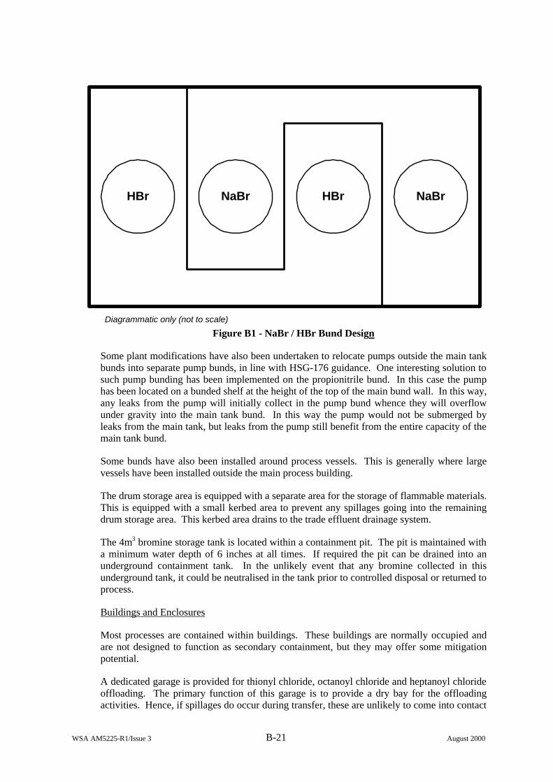
WSA AM5225-R1/Issue 3 B-21 August 2000
HBr NaBr HBr NaBr
Diagrammatic only (not to scale) Figure B1 - NaBr / HBr Bund Design
Some plant modifications have also been undertaken to relocate pumps outside the main tank bunds into separate pump bunds, in line with HSG-176 guidance. One interesting solution to such pump bunding has been implemented on the propionitrile bund. In this case the pump has been located on a bunded shelf at the height of the top of the main bund wall. In this way, any leaks from the pump will initially collect in the pump bund whence they will overflow under gravity into the main tank bund. In this way the pump would not be submerged by leaks from the main tank, but leaks from the pump still benefit from the entire capacity of the main tank bund.
Some bunds have also been installed around process vessels. This is generally where large vessels have been installed outside the main process building.
The drum storage area is equipped with a separate area for the storage of flammable materials. This is equipped with a small kerbed area to prevent any spillages going into the remaining drum storage area. This kerbed area drains to the trade effluent drainage system.
The 4m3 bromine storage tank is located within a containment pit. The pit is maintained with a minimum water depth of 6 inches at all times. If required the pit can be drained into an underground containment tank. In the unlikely event that any bromine collected in this underground tank, it could be neutralised in the tank prior to controlled disposal or returned to process.
Buildings and Enclosures
Most processes are contained within buildings. These buildings are normally occupied and are not designed to function as secondary containment, but they may offer some mitigation potential.
A dedicated garage is provided for thionyl chloride, octanoyl chloride and heptanoyl chloride offloading. The primary function of this garage is to provide a dry bay for the offloading activities. Hence, if spillages do occur during transfer, these are unlikely to come into contact
WSA AM5225-R1/Issue 3 B-22 August 2000
with surface water. Therefore, although the garage does not have a forced ventilation system or scrubber, the building could be considered as a means of secondary containment since any contact of the leaking material with water would greatly increase the ‘source term’ of evolved gases. The extent of the cover provided by the building was subject to some assessment, and it was decided that the majority of the risk reduction could be obtained by covering the offloading area only. The storage tanks and associated bund are therefore not enclosed. It is interesting to note that this is a form of secondary containment that is designed to keep water out rather than preventing gases escaping.
Dump Tanks, Quench Vessels and Scrubbers
Quench vessels are employed in some of the processes. Most distillation stills vent to dump tanks that are located locally within the relevant process building. Every process scrubs off-gases and many processes are equipped with primary and secondary back-up scrubbers.
On some high risk processes, such as those involving ammonia or HBr, towns water header tanks are installed to provide emergency water should site power failure occur.
Bursting Discs
The site incorporates one case of a bursting disc followed by a relief valve vent arrangement.
Water Spray
There are no fixed water curtains, but the site emergency response teams are trained in the use of fire hoses to knock out vapour clouds. The site fire service always mobilise and make provision for a water curtain local to the anhydrous ammonia storage facility whenever offloading activities take place. Typically this is at least once per week.
Covers and Mobile Devices
The site has a dedicated emergency response capability. The on site fire response vehicle is equipped with various absorbents such as pigs, sheets and granules. They also carry absorbent socks that can be used to block off drains in case of a spill.
Overdrums are available on site, as are clamps and drum patches. The emergency response team also have pneumatic patches that could be applied to small ruptures in bulk tanks or pipes.
3. Codes, Standards and Procedures
Aventis adopt Rhone-Poulenc guidance where appropriate; however, the company guidance does not supersede local laws, regulations or guidelines that define the required level of safety. UK guidelines adopted by Aventis include, for example:-
• Specialist Inspectors Report (SIR) 39, Guidance on bunding of bulk chemical storage vessels.
• Chemical Industries Association (CIA) Guidance on the transfer of ammonia.
• HSE guidance notes (HSG-176 for flammables, HSG-30 for ammonia)
Rhone-Poulenc guidance on hazardous liquid storage facilities suggests that the bund capacity should be at least 100% of the volume of the largest tank. In addition, the bund should be

WSA AM5225-R1/Issue 3 B-23 August 2000
capable of containing at least 50% of the entire volume contained within, and the bund wall should be at least 3 feet from the nearest storage tank.
All bunded flammable storage tanks on site are bunded with a volume of 110% of the size of the largest vessel within the bund.
It was noted that there does not appear to be any published HSE guidance on bunding of bromine. Aventis therefore adopt supplier guidance regarding the storage of their bromine.
The preferred site design philosophy is to install vertical bulk storage tanks mounted on skirts such that the base of the tank remains visible. All bunds are concrete and those containing acid storage are additionally painted with resistant coatings (such as, for example, ‘proderite’).
4. Incidents and Operational Experience
Incidents
Incidents relating to secondary containment include:-
• Some years ago a release occurred into a bund on the North site which drained from the bund due to a drainage valve being inadvertently left in the open position. This valve has subsequently been removed.
• Around 200 litres of caustic was lost from a process flange in 1997. The released material dripped through process areas since the floors in the vicinity are grated.
Operational Experience
Flange guards are not widely used on site but some consideration has been given to their usage following the caustic leakage incident described above. Any adoption of such devices would be dependent principally upon flange duty and location, with the main reason for deployment being personnel protection. There is no overall corporate policy to fit flange guards since it is envisaged that they have the drawback of making leaks more difficult to detect and simply act to delay a leakage becoming manifest to the surroundings.
It was noted that raising the level of a pump such that leaks could drain into the main tank bund could cause operational problems with respect to priming the pump. This was not a problem for the propionitrile pump on this site since the storage tank was also raised on pillars.
Other Issues
It is interesting to note that the design of the NaBr / HBr bund partition was complicated by the fact that the existing HBr tank was originally located between the two adjacent NaBr tanks.
WSA AM5225-R1/Issue 3 B-24 August 2000
Site: Site 5
Date of Visit: 24th March 2000
1. Introduction
The operations at Site 5 were established in the 1950’s on a previously greenfield site.
The developed part of the site covers around 90 acres, close to a river. The river is down wind of the prevailing wind direction. The nearest residential area is some three quarters of a km away in an area that is upwind of the prevailing wind direction.
The Company manufactures a range of pharmaceutical intermediates and chemicals for the crop protection and animal health businesses. A small number of products are also toll-manufactured on site for another Company. All processes carried out on site are either batch or semi-batch.
A wide range of flammable materials are stored on site.
The principal toxic materials stored on site are
• Chlorine (23 tonnes maximum)
• Dimethylformamide (DMF)
• Methanol (also flammable)
2. Secondary Containment Provisions
The following secondary containment methods are employed on the site:
• site design and drainage
• fixed bunds
• buildings and enclosures
• dump tanks, quench vessels and scrubbers
• bursting discs/relief valves
• double skinned equipment
• underground tanks
• water spray
• covers and mobile devices
WSA AM5225-R1/Issue 3 B-25 August 2000
Site Design and Drainage
The process buildings are each equipped with separate interceptor pits which each transfer separately to a common Effluent Treatment Plant (ETP). Effluents are initially treated locally at the source process building before being discharged to the ETP. This strategy provides a cost-effective and environmentally acceptable approach and reduces the loading on the ETP. All surface water also transfers to the ETP.
In compliance with Company policy, a large dike is situated along the side of the site to collect and retain firewater run-off from the warehouse. This dike is lined with an impermeable membrane and is drained via a penstock valve to the ETP. The penstock valve is maintained in the open position unless the fire alarm is initiated in which case it is automatically closed.
Potential leaks in the on-site tanker offloading areas would drain to the ETP via the process area drainage.
All site drain covers are colour coded to distinguish between surface water drainage and process area ‘surface’ drainage.
The site has an Environment Agency deemed consent to discharge effluent from the ETP into the deep water channel of the river estuary at a distance of some 1.4 km from the site boundary. All site effluents are ultimately discharged offsite via this route. The effluent discharge is continuously monitored.
Fixed Bunds
All storage tanks containing flammable material are bunded. The majority of these bunds comply with company preferred standards and incorporate the following design features:
• Storage tanks are raised on pedestals
• Storage tanks are equipped with linear tape heat detectors
• Storage tanks have an automatic deluge system
• Bund is equipped with foam inductors
• Bund floor is sloped steeply towards a catchment pit at one end
• Capacity of bund is at least 110% of capacity of largest tank
• The catchment pit is separated from the main bund by a large firewall extending to the full height of the vertical tanks.
All flammables are bunded separately from non-flammables.
The only exception to this is a small pharmaceutical manufacturing facility that has flammable materials stored in a bund which complies with the company ‘minimum’ design standard. This contains highly flammable recovered MEK, amongst other flammables. On this bund the offloading pumps are located outside the bund whereas the process transfer pumps are located inside the bund. The offloading area is sloped towards the process area drainage channels but some surface water drains are located close by.
WSA AM5225-R1/Issue 3 B-26 August 2000
The bunds which conform to the ‘preferred’ company standard for flammable materials have all pumps located outside the bund, including the process transfer pumps. Leaks from these pumps would therefore drain to the appropriate building interceptor pit. Those bunds that contain either caustic or acidic storage tanks are coated with ‘ucrete’.
The chlorine tanks are bunded within a chlorine storage building. The bund is partitioned such that each of the two tanks has a separate bund. The bund is also fitted with chlorine detectors.
It was noted that the pump serving the waste acid tank is mounted on a shelf at a high level on the bund wall. In this way, leaks into the bund would not submerge the pump but a leak from the pump would benefit from the full containment capacity of the tiled bund.
Buildings and Enclosures
The chlorine offloading, storage and vaporising facilities are contained within a building. The offloading and storage facilities are contained within separate sections of the building and are vented through a common scrubber. The scrubber is operated during offloading, during maintenance or if a chlorine leak is detected. The chlorine vaporisers are contained in a further section of the building which is also vented to the scrubber. All sections of the building are equipped with chlorine detectors.
There is a bund beneath the chlorine storage tanks but the tanker offloading area is separately drained.
The chlorine offloading area is served by two roller shutter doors which are interlocked to prevent offloading when the doors are in the open position.
The phosgenation process is housed within a normally unmanned process building. This building is equipped with a scrubber system. The access door to the building is locked and has controlled entry. The building is treated as a confined space with respect to personnel entry. Personnel entry is strictly prohibited whilst phosgenation is underway.
Flammable materials in drums are stored in a flammable drum store. This has enclosures that are equipped with sprinkler systems (except for those bays containing water reactant materials).
Dump Tanks, Quench Vessels and Scrubbers
There are two 35 tonne chlorine storage tanks. The installation is always operated with one of these tanks empty such that, should a failure occur in the ‘duty tank’, the entire contents of the tank could be readily transferred to the empty tank.
The hydrogenation buildings are equipped with dump tanks and associated vent systems.
There are dedicated scrubbers serving each of the process buildings. These scrubbers then feed into a common vent header which is served by a further scrubber. In addition, some process reactions are equipped with dedicated scrubbers, both primary and back-up in some cases.
WSA AM5225-R1/Issue 3 B-27 August 2000
Double Skinned Equipment
The phosgene transfer line is a double pipe line incorporating a swept air system. The air is analysed for phosgene and hence a leak from the primary transfer line could be detected. This system would not necessarily identify the exact location of the leak.
Underground Tanks
Surface water from the gatehouse and visitors car park area is collected in a large underground tank which is equipped with a level detector. This provides secondary containment for any spillages that might occur from road tankers in or near the site entrance.
Bursting Discs
Some processes contain double bursting disc arrangements and in some cases the inter-spatial pressure is monitored.
Water Spray
The site emergency response team is able to set up water curtains as required using mobile fire monitors.
Covers and Mobile Devices
The site policy is to have bulk storage of materials feeding directly to process wherever possible. When drums are required to be moved into a process area, they are stored locally on simple wooden pallets. The site emergency response team is able to apply a range of mobile devices around the site including drum overpacks, absorbents and clamps etc.
3. Codes, Standards and Procedures
The principal company guideline related to secondary containment concerns bund design. The guideline for ‘safety measures for tank farms for flammable liquids’ contains recommended practice for the design of such bunds. This document has previously been reviewed by the HSE and found to satisfy or exceed the provisions of the equivalent HSE guidelines HSG-50 (subsequently superseded by HSG-176). Most bunds on site are constructed to the ‘preferred’ design stipulated in the company guidelines, with only one bund being designed to the ‘minimum’ standard stipulated in the guidelines.
4. Incidents and Operational Experience
Incidents
No incidents relevant to secondary containment issues were reported.
Operational Experience
It was noted that a warehouse annex, sited some distance away from the main warehouse, was also equipped with extended drainage that allowed firewater run-off to drain into the large retention dyke.
WSA AM5225-R1/Issue 3 B-28 August 2000
Other Issues
It was noted that the newest flammable materials bund that conforms to the company preferred standard was constructed by sinking the bund into the ground rather than having elevated bund walls. This would be expected to provide greater integrity with respect to resisting dynamic loading. In addition, a concreted services trench ran immediately adjacent to the bund wall at the opposite side to the catchment pit. This would help to provide some degree of tertiary containment should a leak overtop the bund wall in this area.
WSA AM5225-R1/Issue 3 C-1 August 2000
APPENDIX C
INCIDENT REPORTS
This Appendix gives summaries of a selection of incidents in which secondary containment issues played a significant part, or would have done if they had been present. The overall findings are discussed in Section 5 of the main report.
WSA AM5225-R1/Issue 3 C-2 August 2000
Reference: I-01
Place & Date: Cincinnati, Ohio, USA – 8th January 2000
Type of release: Fertiliser
Overview of Incident:
A storage tank ruptured releasing almost 365,000 gallons of liquid fertiliser into the Ohio River. The force of the liquid flowing from the tank pushed two trucks into the river, breaking a cord that moored a nearby barge.
Review of Secondary Containment Issues:
No secondary containment system was in place to hold the contents of the storage tank. If there had been some form of containment, such as a bund wall around the tank, the release to the environment may have been prevented.
Reference: I-02
Place & Date: Harrodsburg, Kentucky, USA – 2nd October 1999
Type of release: Diesel oil
Overview of Incident:
An above ground diesel oil storage tank ruptured releasing an estimated 38,500 gallons of oil which spilled into the dry bed of Curds Creek. A clean up operation was put into place and at least 20,000 gallons were recovered.
Review of Secondary Containment Issues:
No secondary containment system was in place to hold the contents of the storage tank. Some form of containment, such as a bund wall around the tank, would have prevented the diesel oil from being released and contaminating the riverbed.
Reference: I-03
Place & Date: BASF, Mannheim, Germany – 29th May 1999
Type of release: Phthalic acid esters
Overview of Incident:
Approximately 200m3 of the plasticizer phthalic acid ester leaked from a storage unit and contaminated soil on Frisenheimer Insel, an island in the Rhine. The source of the leak was thought to be a rusty disused pipe. BASF is undertaking clean up of an estimated 10,000 tonnes of soil.
WSA AM5225-R1/Issue 3 C-3 August 2000
Review of Secondary Containment Issues:
No secondary containment system was in place to hold the contents of the storage unit. Some form of containment such as a bund wall around the tank would have prevented the plasticizer from being released and contaminating the soil. Thorough maintenance and inspection routines should have picked up the faulty pipe and therefore prevented the incident.
Reference: I-04
Place & Date: Yokohama, Japan – 2nd July 1997
Type of release: Crude oil
Overview of Incident:
A ship carrying 257,000 tonnes of crude oil ran aground scraping a shallow reef. Two of the fourteen oil tanks on the ships were ruptured. Approximately 1300 tonnes spilt to the sea and oil booms were set up to stop the oil from spreading. After inhaling fumes, 15 people were taken to hospital. Review of Secondary Containment Issues:
Although the booms helped to contain the oil and prevent further spreading, they did not provide a means of total recovery of the oil spill.
Reference: I-05
Place & Date: ICI, Runcorn, Cheshire UK – 9th April 1997
Type of release: Chloroform
Overview of Incident:
A leak from a broken filter resulted in a 3ft fountain of chloroform gushing from a pipe, which went undetected for 4½ hours. In total, 147 tonnes of chloroform escaped with only about three tonnes being recovered. An estimated one tonne leaked into the Weston Canal, 20 tonnes evaporated into the air and the remaining 123 tonnes soaked into the ground. The Weston Canal joins the River Weaver at Sutton Weir where the Environmental Agency regularly tests water quality for compliance with Environmental Quality Standards (EQS). Two days after the spill the reading for chloroform was 493 parts per billion compared with an annual average of 12 parts per billion. The spillage will also cause significant contamination to the site’s groundwater for a considerable amount of time. Although there were no reports of anyone suffering any ill effects due to the spill, the inhalation of chloroform can cause drowsiness, headache, nausea and even unconsciousness. A prolonged exposure can cause kidney and liver damage and could even be fatal.
Review of Secondary Containment Issues:
The pipe designed to carry chloroform was not kept in good condition and ICI failed to install adequate plant-based containment on the site. There was inadequate instrumentation to detect the declining level of chloroform in the stock tank, which was falling at a rate of 30 tonnes per hour during the incident. If secondary containment provisions had been in place to contain plant areas,
WSA AM5225-R1/Issue 3 C-4 August 2000
tank bunds, storage areas, loading bays, wash bays and drainage systems, the surrounding ground water would not have been contaminated.
This chloroform spillage led to prosecution by the Environment Agency resulting in a fine of £300,000 for ICI, who were also ordered to pay £51,193 in costs.
Reference: I-06
Place & Date: Baytown, Texas, USA – 23rd February 1997
Type of release: Lubricating oil
Overview of Incident:
Tanks overflowed during a transfer operation resulting in a large spillage of lubrication oil into the Houston ship channel. Approximately 10,500 gallons were recovered. Despite the deployment of booms and the use of absorbent pads, 4200 gallons reached the boundary of Alexander Island.
Review of Secondary Containment Issues:
Although booms helped to contain the oil and prevent further spreading, they did not provide a means of total recovery of the oil spill.
Reference: I-07
Place & Date: Billingham, Cleveland, UK – 16th January 1997
Type of release: Methyl methacrylate
Overview of Incident:
A problem that caused waste to back up in pipes resulted in 4 tonnes of methyl methacrylate seeping from a bund into the River Tees. The release occurred at a monitored outlet and an alarm sounded. An investigation was launched but the chemical leak continued for almost 5 hours.
Review of Secondary Containment Issues:
Although there was a bund in place it was not of a suitable design to prevent a leakage when the plant was experiencing problems. The long delay in stopping the leak also points to inadequate secondary containment procedures on the site.
Reference: I-08
Place & Date: Heaven Hill Distillery, Kentucky, USA – 7th November 1996
Type of release: Burning alcohol and fire water run off
WSA AM5225-R1/Issue 3 C-5 August 2000
Overview of Incident:
A fire in a Bourbon Whiskey warehouse caused the building to collapse and crushed barrels sent burning alcohol flowing down hill. This spread the fire to two further warehouses, and, as subsequent warehouses collapsed, their contents added to the flaming run off problem. Shallow drainage ditches were filled with flaming alcohol and an 18-inch deep flood of flaming bourbon covered the main road linking the warehouses. The fire totally destroyed 50% of the distillery buildings with minor damage to the remainder. During the fire, alcohol spilled into a creek feeding the Beech Fork River although the pollution hazard was reduced by a rain storm downpour.
Review of Secondary Containment Issues:
None of the warehouses were equipped with sprinkler fire suppression systems, which could have helped to contain the fire and reduce the extent of damage. No secondary containment or drainage system was in place to help prevent the spread of the burning alcohol across the site or to retain the fire water run off. Had there been some form of containment to prevent the escaping water from being released, the river would not have been contaminated.
Tougher state laws in Kentucky require that whiskey warehouses built after 1994 are constructed of concrete and shall include sprinkler suppression systems and drainage systems.
Reference: I-09
Place & Date: Runcorn, Cheshire, UK – 3rd October 1996
Type of release: Vinylidene chloride
Overview of Incident:
An operator was transferring a mixture of vinylidene chloride and water into a separator, which overflowed into a bund when an indicator failed. Following other errors, the mixture leaked from the bund and went into a canal. The company was fined £34,000.
Review of Secondary Containment Issues:
Although there was a bund in place, it failed to retain the leakage during the course of errors that occurred. The secondary containment should have prevented any spillage from the bund to the canal.
Reference: I-10
Place & Date: Bakar Bay, Croatia – 19th March 1996
Type of release: Crude oil
Overview of Incident:
A large leak from a tank at a refinery resulted in 30 tonnes of oil spilling to sea off the Adriatic Coast. Booms close to the tank contained all but 2 tonnes of oil but high winds spread the slick to 90 fishing vessels, several harbours and a sandy beach.
WSA AM5225-R1/Issue 3 C-6 August 2000
Review of Secondary Containment Issues:
Although booms helped to contain the oil and prevent further spreading, they did not provide a means of total recovery of the oil spill. The bad weather further reduced their effectiveness in this case.
Reference: I-11
Place & Date: Hailsham, East Sussex, UK – 17th July 1995
Type of release: Hydrochloric acid
Overview of Incident:
A leakage of 250 tonnes of hydrochloric acid occurred from a cone roof tank. A bund wall contained half of the spill; the rest escaped into a river and required neutralisation.
Review of Secondary Containment Issues:
It is not clear from this incident report if the bund wall was insufficiently sized for the spillage or if there was a structural failure. Well designed and maintained secondary containment could have prevented this release and subsequent pollution of the river.
Reference: I-12
Place & Date: Suplacui, Romania – 30th December 1994
Type of release: Oil
Overview of Incident:
Oil leaked into the river during a refinery processing accident leading to down stream pollution. The clean-up operation was hampered by adverse weather. Booms downstream in Hungary halted the further spread of oil.
Review of Secondary Containment Issues:
The use of booms prevented the oil from spreading any further and helped to contain the spill. Although they provided some secondary containment, they did not give a means of total recovery of the spill.
Reference: I-13
Place & Date: Dronka, Egypt – 2nd November 1994
Type of release: Liquid fuel
WSA AM5225-R1/Issue 3 C-7 August 2000
Overview of Incident:
A release of liquid fuel from a depot of eight tanks occurred during a rainstorm, thought to be a result of lightning. The blazing fuel flowed into the village of Dronka and the death toll was put at more than 410.
Review of Secondary Containment Issues:
There was no secondary containment in place to contain the release. If well designed bunding and good drainage systems had been in place, the burning fuel may have been contained on the site without spreading the fire.
Reference: I-14
Place & Date: Newport, Gwent, UK – February 1994
Type of release: Heavy fuel oil
Overview of Incident:
A site delivery of 550 gallons of heavy fuel oil was pumped into a tank that was being repaired. The fuel oil flowed through the tank, and thence through the bund, which was also being maintained, and into the River Ebbw. The delivery was unsupervised and the tank was not marked with any warning signs. The two companies were both fined £15,000 for polluting the river.
Review of Secondary Containment Issues:
As there was a bund wall in place to retain any spillages, the secondary containment requirements were satisfied. It was unfortunate that the maintenance coincided with the oil delivery and a breakdown in site communication.
Reference: I-15
Place & Date: Associated Octel Company Limited, Cheshire, UK – 1st Feb 1994
Type of release: Ethyl chloride mixed with hydrogen chloride
Overview of Incident:
A release of reactor solution from a recirculating pump occurred near the base of a 25 tonne ethyl chloride reactor vessel. The reactor solution was highly flammable, corrosive and toxic, mainly consisting of ethyl chloride, mixed with hydrogen chloride and small quantities of solid catalyst, aluminium chloride. A dense white cloud enveloped the plant and began to move off-site. The on-site and external emergency services were called in accordance with pre-arranged procedures for major incidents involving chemical release. Action was taken to isolate the leak and suppress further release of the vapour, and prevent the cloud spreading. Despite this, a pool of liquid continued to collect, and the flammable vapours of ethyl chloride ignited almost two hours after the release, causing a major pool fire, which was most intense at the base of the reactor. As the incident developed there were also fires at flanges damaged in the fire, including jet flames at the top of two large process vessels on the plant.
WSA AM5225-R1/Issue 3 C-8 August 2000
Review of Secondary Containment Issues:
The escaping reactor solution collected resulting in intense flames at the base of the reactor. If properly designed secondary containment had been in place, the reactor solution would have drained away to a place where it could have been allowed to burn harmlessly.
Reference: I-16
Place & Date: Long Beach, California, USA – 23rd November 1992
Type of release: Gasoline and LPG
Overview of Incident:
A fire destroyed one storage tank and damaged many others. The large amount of water used to fight the fire resulted in the bund wall being breached. The petroleum and water mixture spilled into the storm sewers and the river.
Review of Secondary Containment Issues:
There was a bund wall to retain any spillages; however, a drainage system to hold the fire water should have been in place. This would have prevented the bund wall failure and subsequent release to the environment.
Reference: I-17
Place & Date: Tallinn Bay, Estonia – 2nd September 1992
Type of release: Diesel oil
Overview of Incident:
A tank wagon derailed leaking 50 tonnes of diesel oil to the harbour. Booms were put in place, but were unable to retain the resulting oil and the resulting slick, which spread over three quarters of the bay.
Review of Secondary Containment Issues:
Although booms helped to contain the oil and prevent further spreading, they did not provide a means of total recovery of the oil spill.
Reference: I-18
Place & Date: Allied Colloids Limited, Low Moor, Bradford, UK – 21st July 1992
Type of release: Fire water run off
WSA AM5225-R1/Issue 3 C-9 August 2000
Overview of Incident:
A series of explosions led to an intense fire in a warehouse that took 3 hours to bring under control. The stored products reacted with water in such a way that site drains and pumping systems became blocked. The four million gallons of water used for cooling and extinguishing purposes could not be contained on the site or the treatment plant and were eventually released finding their way into the Aire and Calder rivers causing significant pollution. The location of the warehouse at the top of the site slope resulted in water and chemical debris flowing down into several manufacturing areas making them uninhabitable. The fire gave rise to a toxic plume and 33 people (including residents, fire fighters and police officers) were taken to hospital, mostly suffering from smoke inhalation.
Review of Secondary Containment Issues:
The secondary containment or drainage system in place was insufficient to deal with the fire water run off from the site. Had there been more suitable containment measures in place to prevent the water from being released, the rivers would not have been contaminated.
Since the fire, efforts have been concentrated on designing and installing a water supply and drainage and retention systems. These systems ensure that sufficient water is available for fire fighting, with fire water, rain water and contaminants monitored and treated if required before disposal. A system of bunding has been incorporated which should only allow overflow through the front loading doors and then into the site-wide water catchment system. The hazardous storage areas have been designed to ensure that any spillages are contained at source by bunding around each group of units. The warehousing facilities were changed with separate stores designated for holding non hazardous materials, raw materials and finished products.
Reference: I-19
Place & Date: Bangkok, Samut Prakam, Thailand – 25th April 1992
Type of release: Bunker oil
Overview of Incident:
Crew opened the wrong valve on a coastal tanker carrying 60,000 litres of bunker oil. As a result, water entered the vessel, which later sank. The resulting oil slick was surrounded with 200m of booms and a skimmer was used to suck it up. An estimated 10,000 litres of bunker oil escaped to the river.
Review of Secondary Containment Issues:
Although booms helped to contain the oil and prevent further spreading, they did not provide a means of total recovery of the oil spill.
Reference: I-20
Place & Date: Immingham, Humberside, UK – 14th November 1989
Type of release: Benzene
WSA AM5225-R1/Issue 3 C-10 August 2000
Overview of Incident:
A shore storage tank was overfilled, resulting in a spillage of benzene. The main part of the spill was retained in the bund, but 20 tonnes was released into a river.
Review of Secondary Containment Issues:
It is not clear whether the bund capacity was insufficient or whether there was a structural failure. The secondary containment provisions in place should have been sufficient to prevent any chemical contaminants from leaving the site, therefore preventing any environmental damage.
Reference: I-21
Place & Date: Azotas Fertiliser Plant, Jonova, Lithuania – 20th March 1989
Type of release: Ammonia
Overview of Incident:
A storage tank experienced over-pressurisation and burst on one side, releasing ammonia. At the same time, the whole tank was dislodged from the foundation and smashed with great force through the surrounding retention wall of reinforced concrete. Devastation around the tank was enormous and liquid ammonia around the fertiliser factory and stores was up to 0.70m in depth. Large quantities of ammonia evaporated and suddenly the vapour caught fire and the whole area was engulfed in flames. The ammonia vapour and nitrous fumes (resulting from fertiliser decomposition) spread up to 35km, forming a contamination zone with an area up to 400km2. After 12 hours all the ammonia had evaporated but the fertiliser continued to burn for three days, evolving great quantities of nitrous fumes. The official number of fatalities was seven.
Review of Secondary Containment Issues:
The retention wall surrounding the ammonia tank was made of reinforced concrete with a thickness of 0.4m and a height of 14.1m, so there were secondary containment provisions in place. However, the design was not sufficient to prevent the ammonia tank crashing through the wall and the subsequent loss of ammonia.
Reference: I-22
Place & Date: Pulua Merlimau, Singapore – 25th October 1988
Type of release: Naphtha
Overview of Incident:
After two days of heavy rain, a floating roof on a naphtha tank became jammed whilst operators were pumping out the tank. A foam blanket was being applied over the exposed naphtha surface when ignition occurred. The ignition source is believed to have been from friction sparks generated by contact between the floating roof and the antI-rotation bar. About 2 hours later a second naphtha tank ignited, with a third tank igniting a further 8 hours later. Another tank was ignited 30 hours later.
WSA AM5225-R1/Issue 3 C-11 August 2000
Review of Secondary Containment Issues:
The tank seal areas were foam protected and there was a water curtain between the tanks to protect against radiated heat, but these systems proved to be ineffective.
Reference: I-23
Place & Date: Port Arthur, Texas, USA – 8th June 1988
Type of release: Propane
Overview of Incident:
A catastrophic failure of a 6-inch propane line at a refinery tank farm pump station led to ignition of the resulting vapour cloud. Numerous other lines in the 50-foot trench subsequently failed and the intense fire quickly enveloped four floating roof tanks containing raffinate, debutanized aromatic concentrate and slop. There was difficulty isolating the tanks and pipelines and the fire spread for a distance of 1300 feet through the trench. The fire was extinguished 20 hours later.
Review of Secondary Containment Issues:
The secondary containment provisions should have enabled easier isolation of the tanks and prevented the fire spreading through the trench.
Reference: I-24
Place & Date: Monongahela River, Pittsburgh, Pennsylvania, USA – 2nd Jan 1988
Type of release: Diesel fuel
Overview of Incident:
A 48 year old cone roof tank was undergoing its initial fill after relocation to a river terminal when the tank failed catastrophically, spilling 92,400 barrels of diesel fuel. The fuel overflowed the tank bund wall and a large part of it entered the Monongahela River.
Review of Secondary Containment Issues:
It is not clear whether the bund capacity was insufficient or whether there was a structural failure. The secondary containment provisions in place should have been sufficient to prevent any chemical contaminants from leaving the site, thus preventing any environmental damage.
Reference: I-25
Place & Date: Australia – 29th November 1986
Type of release: C4 heavy ends
WSA AM5225-R1/Issue 3 C-12 August 2000
Overview of Incident:
Sparks resulting from flame cutting 3m away from a tank vent caused a fire at the base of the tank. This ignited flammable vapours in the tank vent, resulting in an explosion, which separated the tank bottom from the shell. The shell and roof of the tank rocketed 90m from the site. This released 28,000 litres of flaming C4 heavy ends into the bund, which did not have sufficient capacity. As a result, the flaming liquid overflowed to surrounding areas.
Review of Secondary Containment Issues:
The secondary containment provisions in place were inadequate, as they should have been sufficient to hold the tank contents. This might have reduced the severity of the fire damage and would have prevented any environmental damage.
Reference: I-26
Place & Date: Sandoz Schweizerhalle Works, Basel, Switzerland – 1st Nov 1986
Type of release: Fire water run off
Overview of Incident:
A fire broke out in a warehouse containing large quantities of agrochemicals. Attempts to extinguish the fire using foam were ineffective, and water had to be used in large quantities. It was not possible to contain this water on site and, as a result, 10,000m3 entered the river Rhine carrying with it 30 tonnes of chemicals including an estimated 150kg of highly toxic mercury compounds dissolved in aqueous concentrates. Severe ecological damage occurred as a result of this incident.
Review of Secondary Containment Issues:
No secondary containment or drainage system was in place to hold the large amount of fire water run off from the site. Some form of containment to prevent the escaping water from being released would have prevented ecological damage to the river.
Since the fire the following steps have been taken:
• the production of insecticides was reduced by 60% by the end of 1986
• the stock of agrochemicals was cut by one third
• the manufacture of all substances which require phosgene was discontinued and no phosgene has been stored at the works since December 1986
• the production and scale of all products containing mercury was discontinued worldwide as from 1st January 1987.
The groupwide safety regulations for storing toxic and flammable substances were redefined taking into account:
• the characteristics of buildings and their equipment
• storage density, volume and procedures
• packaging materials and storage records.
WSA AM5225-R1/Issue 3 C-13 August 2000
Reference: I-27
Place & Date: Panama, USA – 27th April 1986
Type of release: Crude oil
Overview of Incident:
A refinery storage tank containing 35000 tonnes of light crude oil ruptured spilling its entire contents. The force of the oil caused a section of the bund wall to collapse allowing about 7500 tonnes of oil to flow into the refinery area. Some of the oil drained into run-off channels where the oil-water separator could not recover the amount of oil involved. Around 3500 tonnes of oil eventually drained into a bay, which opens into the Caribbean Sea.
An extensive clean up operation was started on the same day.
Review of Secondary Containment Issues:
A bund wall had been constructed around the tank in order to contain any spills. Unfortunately, the design was inadequate for the transient hydrodynamic loads which it experienced. Thus the secondary containment provisions in place were insufficient to prevent any chemical contaminants from leaving the site and preventing any environmental damage.
Reference: I-28
Place & Date: Oil Terminal, Thessalonika, Greece – 24th February 1986
Type of release: Burning oil
Overview of Incident:
An oil spillage in a bund was ignited by hot work and led to a small fire. Due to accumulated oil from previous spillages and common drainage channels through bund walls, the fire spread into adjacent areas. The terminal had twelve fixed and floating roof storage tanks holding crude oil, fuel oil and gasoline. Over the course of 7 days, ground fires escalated until they covered 75% of the terminal area and involved ten of the twelve storage tanks. The escalation of the initial small fire was mainly due to the accumulation of oil from previous spillages; to leaks from flanges exposed to the fire which then fed it; and to the failure of fire fighting efforts in the early stages. During the following days, several events occurred which led to major escalations. On tank 3, overpressure caused the shell floor seam to burst so that the whole contents flowed out, feeding the fire and involving two more tanks. Tank 8 suffered a boilover with a fire ball 300m high and ejection of burning oil over a wide area, some travelling up to 150m. The fire fighting was hampered, and firemen endangered, by burn-back of flame in areas where the oil fire had already been extinguished by foam.
Review of Secondary Containment Issues:
The bunds and drainage systems in place at the terminal should have been designed to enable any oil spillages to drain away safely. This would have helped to prevent pool fires from spilt oil starting and to reduce the chances of escalation. Provision for fire fighting run-off (in this case the foam oil mixture) should also have been in place to ensure that it was safely drained away from the hazardous source, therefore preventing re-ignition.
WSA AM5225-R1/Issue 3 C-14 August 2000
Reference: I-29
Place & Date: Naples, Italy – 21st December 1985
Type of release: Gasoline
Overview of Incident:
A spill of gasoline occurred during a filling operation from a ship berthed in the Naples harbour. Gasoline overflowed through the floating roof of a tank for about 1.5 hours. The fuel storage area was highly confined by walls, buildings and by an embankment, with a mean height of 8m. The total amount of spilled fuel was estimated to be about 700 tonnes. The resulting pool covered the bund area of the tank and the adjacent pumping area, which were connected through a drain duct. A large homogeneous vapour cloud formed due to the low wind speed, relatively high ambient temperature and a long delay prior to ignition. The ignition source was in a pumping station and the resulting blast wave caused 5 casualties within the area. The fire lasted for over a week and destroyed all the buildings and equipment within the area.
Review of Secondary Containment Issues:
There was a bund present to retain spillages but the design did not seem to allow fast draining of the gasoline away from the area. If it had, it may have prevented the build up of the vapour cloud and lessened the amount of fuel available for burning. The connecting drain duct may have also added to the problem.
Reference: I-30
Place & Date: Union Carbide India Ltd., Bhopal, India – 3rd December 1984
Type of release: Methyl isocyanate (MIC)
Overview of Incident:
Early in the morning, the control room operator noticed that the pressure in a storage tank containing highly toxic methyl isocyanate had increased. The relief valve on the tank lifted and a cloud of MIC gas was released. There was a slight wind and inversion conditions which spread the cloud from the plant towards the populated areas to the south. People in the surrounding housing felt the irritant effect of the gas and within a short period, animals and people began to die. The cloud of toxic gas hung over the area for the whole day, moving on towards the city during the night. The two hospitals were overwhelmed with casualties and the situation was made worse since it was not known what the gas was and what its effects were. This resulted in a conflict of views on the appropriate treatment and the company provided little advice. Almost 2000 people died within a short period and tens of thousands were injured.
Review of Secondary Containment Issues:
No secondary containment was in place to contain the venting release from the storage tank. If the MIC gas had been passed through appropriate scrubbers before being released to the environment, the severity of the incident would have been considerably reduced.

WSA AM5225-R1/Issue 3 C-15 August 2000
Reference: I-31
Place & Date: PEMEX LPG Terminal, Mexico City, Mexico – 19th November 1984
Type of release: LPG
Overview of Incident:
The terminal was used for the distribution of LPG that came by pipeline from three different refineries. On the day of the incident the plant was being filled from a refinery 400km away when a drop in pressure was registered in the control room and at a pipeline pumping station as a result of the rupture of an 8-inch pipe. The cause of the pressure drop was not identified by personnel in the control room and the LPG release continued for 5-10 minutes. The slight wind and sloping terrain carried the gas cloud towards the south-west. When it reached the terminal it was ignited by the flare, resulting in a high flame and causing violent ground shock. The first BLEVE occurred 5 minutes later, followed quickly by others, which led to a 300m fireball. There were a further 15 explosions as more vessels underwent BLEVEs in the next 90 minutes. The bursting vessels generated numerous missiles, which travelled up to 1200m causing damage by impact and setting houses alight. The traffic chaos in the area prevented good access for the emergency services. Considerable risk was taken by the fire services because of the potential for further BLEVEs occurring on the site. The terminal was destroyed due to the failure of the overall system of protection. This includes layout, emergency isolation and water spray systems. The high death toll – 500 people were killed – occurred primarily because shanty type housing had been constructed in an uncontrolled manner, too close to the plant. Over the years the development of housing had gradually approached the site.
Review of Secondary Containment Issues:
There was no gas detection system on the site. More effective gas detection and emergency isolation may have averted the disaster. Well designed bunding and good drainage systems may have prevented the storage spheres from overheating and generating BLEVEs, by rapidly removing any burning liquid from around the vessel bases.
Reference: I-32
Place & Date: Kerala, India – 8th March 1984
Type of release: Naphtha
Overview of Incident:
An explosion at a refinery caused fires in two naphtha tanks, a JP-5 tank and a chemical warehouse. Naphtha from damaged pipelines spilled into the bund and ignited. Another tank developed a leak and it also fuelled a bund fire before becoming enveloped. The fire station at the refinery, situated 375 feet from the cooling tower, was damaged and the foam truck disabled. There were delays in the fire fighting until the public service arrived from a station 8 miles away. Although almost 16,000 gallons of foam concentrate was used to fight the fires, they continued for a further 77 hours before burning themselves out.
Review of Secondary Containment Issues:
The foam concentrate did not prove to be effective in either containing or extinguishing the fire.
WSA AM5225-R1/Issue 3 C-16 August 2000
Reference: I-33
Place & Date: El Paso Natural Gas Company, Bloomfield, New Mexico, USA – 26th May 1983
Type of release: Natural gas
Overview of Incident:
A gasket on a compressor failed and natural gas began to escape into the building. The operators attempted to shut off the gas supply to the compressors and shut down the compressor engine. Before this could be done the gas ignited and exploded. Both operators were severely burned and the equipment destroyed.
Review of Secondary Containment Issues:
In this case, it would have been preferable to locate the vessel outside any buildings. Flammable gases that leak outside have a chance of dispersion, although ignition would still be a factor.
Reference: I-34
Place & Date: Tacoa, Venezuela – 19th December 1982
Type of release: Fuel oil
Overview of Incident:
There was an explosion that blew the roof off a storage tank containing 83,000 barrels of fuel oil. The tank burst into flames and oil lines entering through the tank roof were severed allowing oil to enter the bund where it ignited and added to the fire. The tanks had fixed foam fire extinguishing systems, a water cooling system and fog nozzles, but these were damaged in the explosion. The site did not have its own fire brigade and the nearest fire station was 20 minutes away via a dangerous narrow and winding road which soon became crowded with spectators. Hence the fire fighting efforts were extremely limited. After a few hours the fire was considered to be under control and the fires were left to burn themselves out with fire fighters, media and other personnel standing 30 – 60m away. Six hours after the start of the fire there was an unexpected violent boilover, which threw the tank contents hundreds of metres into the air. There was a giant fireball and burning oil overflowed the bund spreading over a distance of 400m. Many people were killed instantly and others were caught in the burning oil as it flowed down the hill. Nearby buildings ignited and burned and 60 vehicles were destroyed. More than 150 people were killed and many homes were destroyed.
Review of Secondary Containment Issues:
Although there was a bund in place, the burning oil was spread a long way by the explosion. If the additional oil added by the oil lines had been drained more quickly away from the bund, the effects of a fire around the base of the tank may have been reduced. This in turn may have lessened or prevented the boilover and the consequential site damage.
WSA AM5225-R1/Issue 3 C-17 August 2000
Reference: I-35
Place & Date: Morley, Yorkshire, UK – 1982
Type of release: Fire water run off
Overview of Incident:
This was similar to the 1986 incident in Switzerland (I-26), although on a smaller scale. A fire in a herbicide warehouse resulted in chemicals being carried by fire fighting water into the river Calder.
Review of Secondary Containment Issues:
No secondary containment or drainage system was in place to hold fire water run off from the site. Some form of containment to prevent the fire water from being released would have prevented contamination of the river.
Reference: I-36
Place & Date: Wethersfield, Connecticut, USA – 22nd December 1980
Type of release: Fuel oil
Overview of Incident:
The pressure of ice against an earthen supporting dock on Connecticut River caused pipelines to rupture with a consequent spillage of around 55,000 gallons of fuel oil into the river. This resulted in a 15 mile long slick. Approximately half of the oil was recovered using booms and a vacuum truck.
Review of Secondary Containment Issues:
Although booms help to contain the oil and prevent further spreading, they do not provide a means of total recovery of the oil spill.
Reference: I-37
Place & Date: Linden, New Jersey, USA – 20th March 1979
Type of release: Propane and butane
Overview of Incident:
A section of piping in a fluid catalytic cracking (FCC) unit failed allowing the release of propane and butane. A vapour cloud developed and covered an area of approximately 1.5 acres to a depth of 5-6 feet when it was ignited. The water sprays were ineffective in dispersing the vapours. An unused control room exploded after filling with vapours. Flying bricks and other debris severed lines in the area releasing hydrocarbons.
WSA AM5225-R1/Issue 3 C-18 August 2000
Review of Secondary Containment Issues:
The water sprays were in place and fully functional, although they were inadequate when faced with the task.
Reference: I-38
Place & Date: Brindisi, Italy – 8th December 1977
Type of release: Gas release from an ethylene unit and fire water run off
Overview of Incident:
A major gas release in the cold section of an ethylene unit was ignited causing severe blast and fire damage. Two nearby ethylene units were also damaged. The control building had brick panel walls within a reinforced concrete frame. The panel walls were blown out by the blast overpressures and the controls were destroyed. The large volume of fire fighting water applied could not be carried off by the sewers, which then resulted in an 18-inch backup of floating burning liquid throughout the process area. After eight hours the fires were brought under control and were extinguished 3 days later. Three people died and over twenty were injured.
Review of Secondary Containment Issues:
The unit should have been positioned away from areas where a release of flammable vapour may have led to severe blast damage. If the unit had been placed in a less confined area the resulting blast damage would have been considerably less.
No secondary containment or drainage system was in place to deal with the large volume of fire water run off from the site. If a system had been in place to enable faster drainage, the fire may not have been spread so far, leading to easier containment by the fire brigade.
Reference: I-39
Place & Date: Umm Said, Qatar – 3rd April 1977
Type of release: Propane
Overview of Incident:
A single walled carbon steel refrigerated atmospheric storage tank holding 37,000m3 of liquid propane catastrophically failed. A wave of propane liquid swept over the bund wall and boiled on the sand. The resulting vapour cloud entered the adjacent separation plant and was ignited. There was a massive fire, which did extensive damage burning out of control for two days and was eventually extinguished after 8 days. Seven people were killed and thirteen were injured.
Review of Secondary Containment Issues:
The bund wall was not suitably designed to retain the leaking propane from the storage tank. If adequate secondary containment had been provided, the resulting consequences may not have been so severe.
WSA AM5225-R1/Issue 3 C-19 August 2000
Reference: I-40
Place & Date: Baton Rouge, Louisiana, USA – 10th December 1976
Type of release: Chlorine
Overview of Incident:
A chlorine storage vessel experienced an internal explosion causing it to fall off its supports and become pierced by a metal stand. Just over 90 tonnes of chlorine were released over a period of almost 6 hours. The resulting gas cloud was 42 miles long and lay over the Mississippi River and sparsely populated areas. Ten thousand people were evacuated and three were treated for minor irritation.
Review of Secondary Containment Issues:
If the storage vessel had been located within a building with scrubbing facilities, the release could have been contained, preventing any damage to the surrounding population or environment.
Reference: I-41
Place & Date: Icmesa Chemical Company, Seveso, Italy – 9th July 1976
Type of release: Vapour cloud including TCDD
Overview of Incident:
A bursting disc ruptured on a chemical reactor resulting in a vapour cloud release from a vent on the roof. The release lasted for 20 minutes and the dense white cloud drifted downwind with material settling out. Among the substances deposited was a small amount of TCDD, one of the most toxic chemicals known. Over the days following the release there was confusion due to the lack of communication between the company and the authorities in dealing with this type of situation. People fell ill and animals died within the contaminated area before a partial and belated evacuation was carried out. No human deaths were attributed to TCDD but a number of pregnant women who had been exposed had abortions.
Review of Secondary Containment Issues:
No secondary containment was in place to hold the vent release from the bursting disc. Had there been some form of containment to prevent the escaping vapour from being released to atmosphere, the surrounding area would not have been contaminated and there would have been no resulting illnesses or deaths.
Reference: I-42
Place & Date: Bulks Terminal Complex, Chicago, Illinois, USA – 26th April 1974
Type of release: Silicon tetrachloride leading to hydrogen chloride cloud
WSA AM5225-R1/Issue 3 C-20 August 2000
Overview of Incident:
A pressure relief valve on a 6 inch line leading into a 3300m3 tank of silicon tetrachloride had been inadvertently closed, resulting in sufficient pressure in the system to burst a flexible coupling in the line. This shifted the piping system and cracked a 3 inch line on the tank wall, resulting in liquid silicon tetrachloride escaping and forming an irritant cloud containing hydrogen chloride. The site emergency plan was not developed, resulting in a situation where nobody knew whose responsibility it was to take action. The cloud was 400m wide, 300-450 m high and 1600m long, 2.5 hours after the release. Almost 16 hours after the release, foam was added to blanket the liquid in the bund, but this failed. After a further 4.5 hours, fuel oil and lime were added which reduced the vaporisation dramatically, and operations began to transfer liquid from the damaged tank. It began to rain 11 hours later resulting in power lines being corroded by the hydrochloric acid and four pumps becoming inoperable due to corrosion before a general power failure stopped all pumping. It was not until 3 days later that the leak was successfully sealed using quick drying cement. It took a further 4 days to empty the tank and another 12 days before the emissions had reduced to tolerable levels.
Review of Secondary Containment Issues:
The materials added to blanket the released liquid reduced the capacity of the bund and a further pit had to be dug to take the overflow from the bund in case of a tank failure. The secondary containment was therefore inadequate considering that blanketing and absorbent materials would need to be added in the event of a major spill.
Reference: I-43
Place & Date: Northern States Power Company, Minnesota, USA – 19th Nov 1971
Type of release: Radioactive waste water
Overview of Incident:
The water storage space at the Northern States Power Company’s reactor filled to capacity and spilled over, dumping about 50,000 gallons of radioactive wastewater into the Mississippi River.
Review of Secondary Containment Issues:
If adequate secondary containment had been in place to retain any overfill, then the escaping wastewater would not have been released. This would have prevented contamination of the river.
Reference: I-44
Place & Date: Longview, Texas, USA – 25th February 1971
Type of release: Ethylene
Overview of Incident:
A 0.5 inch high pressure gas line broke releasing 1000lb of ethylene. The leak was too large for the high density water spray to disperse and the vapour cloud exploded, breaking numerous other pipes and causing the tonnage release of ethylene. The resultant larger vapour cloud ignited giving a violent explosion that was felt over 9 km away. Four people were killed and sixty were treated in hospital.
WSA AM5225-R1/Issue 3 C-21 August 2000
Review of Secondary Containment Issues:
Although there was a water spray in place, it was not adequate for dealing with the released gas cloud. The spray should have been designed to cope with the secondary containment issues that it might face.
Reference: I-45
Place & Date: Gulf Oil Company, Blair, Nebraska USA – 16th November 1970
Type of release: Ammonia
Overview of Incident:
An overflow occurred on a 40,000 tonne refrigerated anhydrous ammonia storage tank as a result of an operator error. The high level alarm and shut down system failed to operate and the isolation valve on the overflow line was impossible to reach due to the ammonia cloud. The release continued for 2.5 hours. Weather conditions were at their most unfavourable for dispersion and a low ammonia cloud formed covering approximately 900 acres and stretching over 9000ft from the tank. A light breeze later helped to keep the cloud from populated areas. There were no deaths or serious injuries.
Review of Secondary Containment Issues:
There was no secondary containment in place to contain the release.
Reference: I-46
Place & Date: Refinery, Feyzin, France – 4th January 1966
Type of release: Propane
Overview of Incident:
Improper sampling procedures on a 12,580-barrel propane sphere led to an uncontrolled release of liquid propane. The alarm was raised and traffic on the nearby motorway was stopped. A car around 200m away ignited the resulting vapour cloud. The storage tank was enveloped in a fierce fire and upon lifting of the relief valve, a stream of escaping vapour ignited above the sphere. The fire brigade arrived on site but was inexperienced in dealing with refinery fires. About 90 minutes after the initial leakage, the sphere ruptured, killing the men nearby. A wave of liquid propane flowed over the compound wall and fragments of the ruptured sphere cut through the legs of the next sphere which toppled over. The relief valve on this tank began to emit liquid. The fire killed 18 people and injured 81 others. Five of the storage spheres were destroyed.
Review of Secondary Containment Issues:
The escaping liquid accumulated beneath the storage sphere rather than draining away from it to a place where it could have been allowed to burn harmlessly. If properly designed secondary containment had been in place, the consequences of the propane leak may have been much less serious.
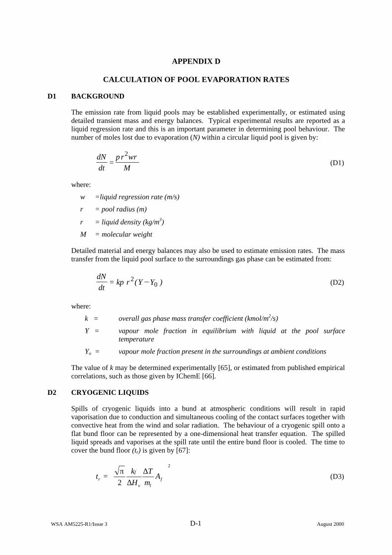
WSA AM5225-R1/Issue 3 D-1 August 2000
APPENDIX D
CALCULATION OF POOL EVAPORATION RATES
D1 BACKGROUND
The emission rate from liquid pools may be established experimentally, or estimated using detailed transient mass and energy balances. Typical experimental results are reported as a liquid regression rate and this is an important parameter in determining pool behaviour. The number of moles lost due to evaporation (N) within a circular liquid pool is given by:
Mwr
dtdN ρπ 2
= (D1)
where:
w =liquid regression rate (m/s)
r = pool radius (m)
ρ = liquid density (kg/m3)
M = molecular weight
Detailed material and energy balances may also be used to estimate emission rates. The mass transfer from the liquid pool surface to the surroundings gas phase can be estimated from:
)YY(rkdtdN
02= π (D2)
where:
k = overall gas phase mass transfer coefficient (kmol/m2/s)
Y = vapour mole fraction in equilibrium with liquid at the pool surface temperature
Yo = vapour mole fraction present in the surroundings at ambient conditions
The value of k may be determined experimentally [65], or estimated from published empirical correlations, such as those given by IChemE [66].
D2 CRYOGENIC LIQUIDS
Spills of cryogenic liquids into a bund at atmospheric conditions will result in rapid vaporisation due to conduction and simultaneous cooling of the contact surfaces together with convective heat from the wind and solar radiation. The behaviour of a cryogenic spill onto a flat bund floor can be represented by a one-dimensional heat transfer equation. The spilled liquid spreads and vaporises at the spill rate until the entire bund floor is cooled. The time to cover the bund floor (tr) is given by [67]:
2
2
∆
∆π
= flv
f
r AmT
Hk
t (D3)
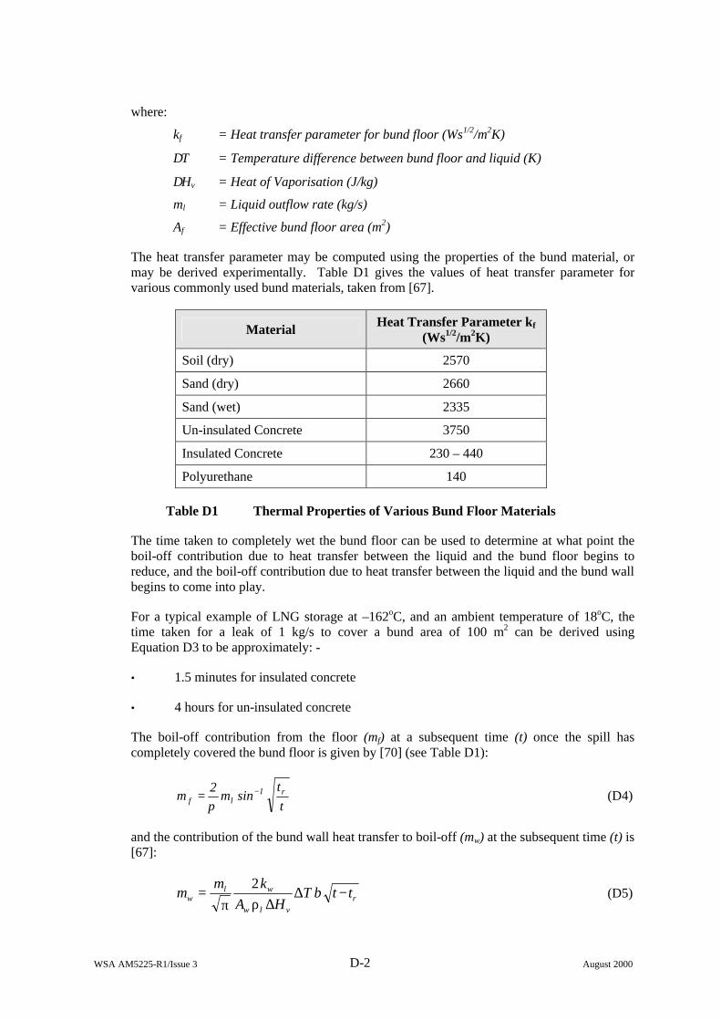
WSA AM5225-R1/Issue 3 D-2 August 2000
where:
kf = Heat transfer parameter for bund floor (Ws1/2/m2K)
∆T = Temperature difference between bund floor and liquid (K)
∆Hv = Heat of Vaporisation (J/kg)
ml = Liquid outflow rate (kg/s)
Af = Effective bund floor area (m2)
The heat transfer parameter may be computed using the properties of the bund material, or may be derived experimentally. Table D1 gives the values of heat transfer parameter for various commonly used bund materials, taken from [67].
Material Heat Transfer Parameter kf (Ws1/2/m2K)
Soil (dry) 2570
Sand (dry) 2660
Sand (wet) 2335
Un-insulated Concrete 3750
Insulated Concrete 230 – 440
Polyurethane 140
Table D1 Thermal Properties of Various Bund Floor Materials
The time taken to completely wet the bund floor can be used to determine at what point the boil-off contribution due to heat transfer between the liquid and the bund floor begins to reduce, and the boil-off contribution due to heat transfer between the liquid and the bund wall begins to come into play.
For a typical example of LNG storage at –162oC, and an ambient temperature of 18oC, the time taken for a leak of 1 kg/s to cover a bund area of 100 m2 can be derived using Equation D3 to be approximately: -
• 1.5 minutes for insulated concrete
• 4 hours for un-insulated concrete
The boil-off contribution from the floor (mf) at a subsequent time (t) once the spill has completely covered the bund floor is given by [70] (see Table D1):
tt
sinm2
m r1lf
−=π
(D4)
and the contribution of the bund wall heat transfer to boil-off (mw) at the subsequent time (t) is [67]:
rvlw
wlw ttbT
HAkm
m −∆∆ρπ
=2
(D5)
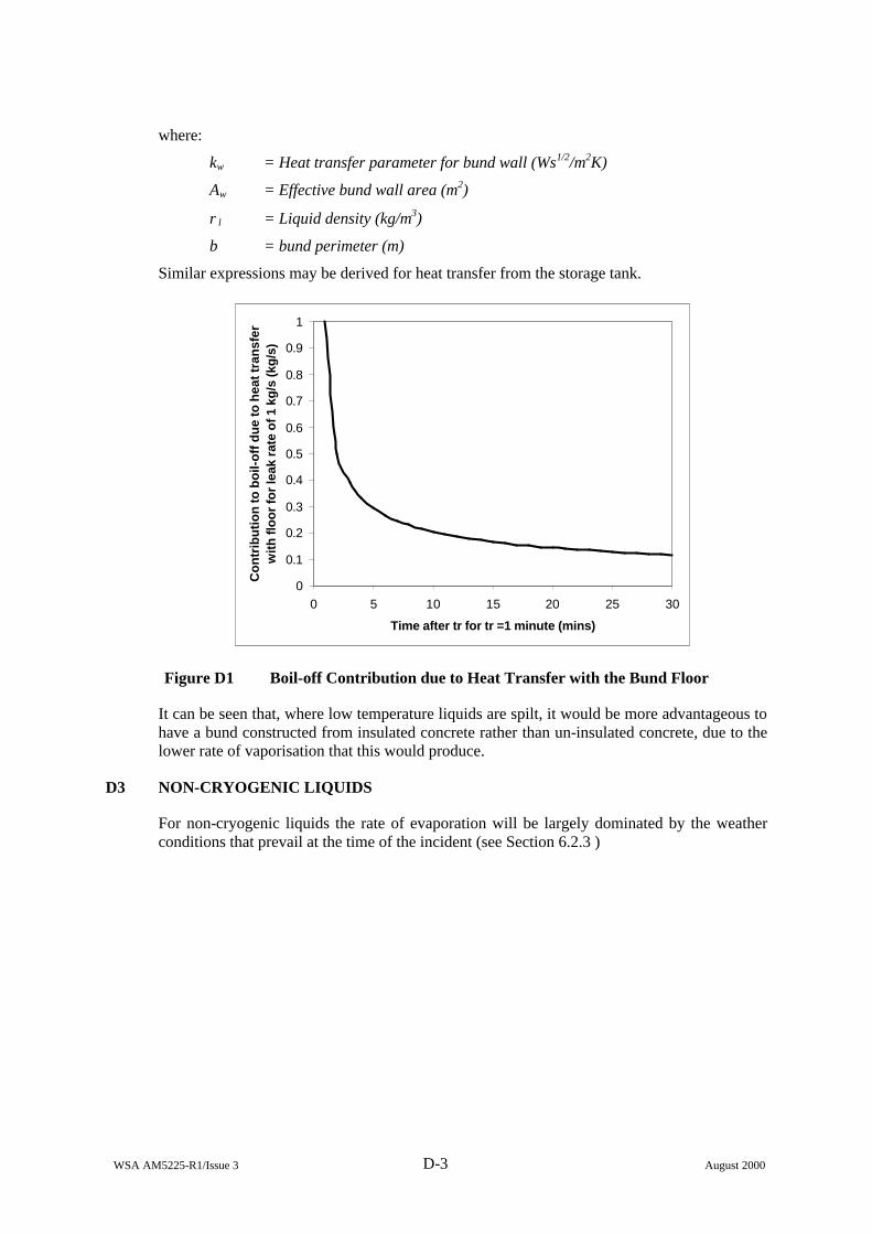
WSA AM5225-R1/Issue 3 D-3 August 2000
where:
kw = Heat transfer parameter for bund wall (Ws1/2/m2K)
Aw = Effective bund wall area (m2)
ρl = Liquid density (kg/m3)
b = bund perimeter (m)
Similar expressions may be derived for heat transfer from the storage tank.
0
0.1
0.2
0.3
0.4
0.5
0.6
0.7
0.8
0.9
1
0 5 10 15 20 25 30
Time after tr for tr =1 minute (mins)
Co
ntr
ibu
tio
n to
bo
il-o
ff d
ue
to h
eat t
ran
sfer
w
ith fl
oo
r fo
r le
ak r
ate
of 1
kg
/s (k
g/s
)
Figure D1 Boil-off Contribution due to Heat Transfer with the Bund Floor
It can be seen that, where low temperature liquids are spilt, it would be more advantageous to have a bund constructed from insulated concrete rather than un-insulated concrete, due to the lower rate of vaporisation that this would produce.
D3 NON-CRYOGENIC LIQUIDS
For non-cryogenic liquids the rate of evaporation will be largely dominated by the weather conditions that prevail at the time of the incident (see Section 6.2.3 )
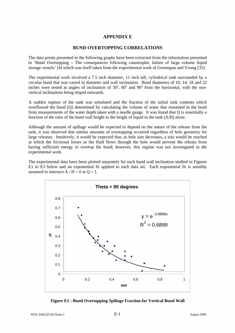
WSA AM5225-R1/Issue 3 E-1 August 2000
APPENDIX E
BUND OVERTOPPING CORRELATIONS
The data points presented in the following graphs have been extracted from the information presented in ‘Bund Overtopping – The consequences following catastrophic failure of large volume liquid storage vessels’ [4] which was itself taken from the experimental work of Greenspan and Young [35].
The experimental work involved a 7.5 inch diameter, 11 inch tall, cylindrical tank surrounded by a circular bund that was varied in diameter and wall inclination. Bund diameters of 10, 14, 18 and 22 inches were tested at angles of inclination of 30o, 60o and 90o from the horizontal, with the non-vertical inclinations being sloped outwards.
A sudden rupture of the tank was simulated and the fraction of the initial tank contents which overflowed the bund (Q) determined by calculating the volume of water that remained in the bund from measurements of the water depth taken with a needle gauge. It was found that Q is essentially a function of the ratio of the bund wall height to the height of liquid in the tank (A/H) alone.
Although the amount of spillage would be expected to depend on the nature of the release from the tank, it was observed that similar amounts of overtopping occurred regardless of hole geometry for large releases. Intuitively, it would be expected that, as hole size decreases, a size would be reached at which the frictional losses as the fluid flows through the hole would prevent the release from having sufficient energy to overtop the bund; however, this regime was not investigated in the experimental work.
The experimental data have been plotted separately for each bund wall inclination studied in Figures E1 to E3 below and an exponential fit applied to each data set. Each exponential fit is sensibly assumed to intersect A / H = 0 at Q = 1.
Theta = 90 degrees
y = e -3.8898x
R2 = 0.6899
0
0.1
0.2
0.3
0.4
0.5
0.6
0.7
0.8
0 0.2 0.4 0.6 0.8 1
A/H
Q
Figure E1 : Bund Overtopping Spillage Fraction for Vertical Bund Wall
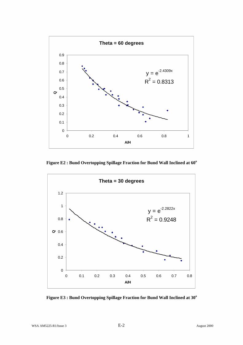
WSA AM5225-R1/Issue 3 E-2 August 2000
Theta = 60 degrees
y = e-2.4309x
R2 = 0.8313
0
0.1
0.2
0.3
0.4
0.5
0.6
0.7
0.8
0.9
0 0.2 0.4 0.6 0.8 1
A/H
Q
Figure E2 : Bund Overtopping Spillage Fraction for Bund Wall Inclined at 60o
Theta = 30 degrees
y = e-2.2822x
R2 = 0.9248
0
0.2
0.4
0.6
0.8
1
1.2
0 0.1 0.2 0.3 0.4 0.5 0.6 0.7 0.8
A/H
Q
Figure E3 : Bund Overtopping Spillage Fraction for Bund Wall Inclined at 30o

WSA AM5225-R1/Issue 3 F-1 August 2000
APPENDIX F
EFFECTS OF LOW WINDSPEED ON RELEASE RATE FROM BUILDINGS: RESULTS OF APPLICATION OF GRAB-T
F1. INTRODUCTION
The current version of GRAB-T allows the user to input any desired windspeed and release (leak) rate for modelling purposes. One of the outputs available is the ventilation flow rate through the chosen openings; an example of which is illustrated below in Figure F1. This shows the flow out from a room through two openings (A in the windward face and B in the leeward face) for a 3kg/s release of chlorine into a full-scale test room, with an external windspeed of 1m/s acting on face A.
-1.5
-1
-0.5
0
0.5
1
1.5
0 200 400 600 800 1000 1200
Time (s)
Flo
w r
ate
(kg
/s)
Figure F1: Mixture flow rate from test room (via two openings)
It should be observed that there is a negative scale on the flow rate axis, which indicates a flow rate into the room through both openings during the early stages of the transient. For such a flow into the room the medium will be air at the defined ambient temperature, whereas for the flow out from the room the medium will be the gas/air mixture at the calculated room temperature.
The driving force behind the flow rates through an opening is the pressure difference between the room contents and that applied to the external wall (with an opening). The pressure inside the room is governed mainly by the release (leak) rate of the pollutant whilst the external pressure is influenced by the ambient windspeed. For the particular case illustrated in Figure F1, the leak rate is sufficient to overcome the wind pressure; for rather lower leak rates, there would only be outflow (of gas/air mixture) from opening B, with inflow (of fresh air) through opening A.
A
B
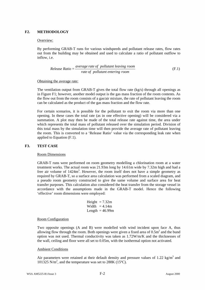
WSA AM5225-R1/Issue 3 F-2 August 2000
F2. METHODOLOGY
Overview:
By performing GRAB-T runs for various windspeeds and pollutant release rates, flow rates out from the building may be obtained and used to calculate a ratio of pollutant outflow to inflow, i.e.
room entering pollutant of rateroom leaving pollutant of rate average
Ratio Release = (F.1)
Obtaining the average rate:
The ventilation output from GRAB-T gives the total flow rate (kg/s) through all openings as in Figure F1; however, another model output is the gas mass fraction of the room contents. As the flow out from the room consists of a gas/air mixture, the rate of pollutant leaving the room can be calculated as the product of the gas mass fraction and the flow rate.
For certain scenarios, it is possible for the pollutant to exit the room via more than one opening. In these cases the total rate (as in one effective opening) will be considered via a summation. A plot may then be made of the total release rate against time, the area under which represents the total mass of pollutant released over the simulation period. Division of this total mass by the simulation time will then provide the average rate of pollutant leaving the room. This is converted to a ‘Release Ratio’ value via the corresponding leak rate when applied to Equation (F.1).
F3. TEST CASE
Room Dimensions
GRAB-T runs were performed on room geometry modelling a chlorination room at a water treatment works. The actual room was 21.93m long by 14.61m wide by 7.32m high and had a free air volume of 1424m3. However, the room itself does not have a simple geometry as required by GRAB-T, so a surface area calculation was performed from a scaled diagram, and a pseudo room geometry constructed to give the same volume and surface area for heat transfer purposes. This calculation also considered the heat transfer from the storage vessel in accordance with the assumptions made in the GRAB-T model. Hence the following ‘effective’ room dimensions were employed:
Height = 7.32m Width = 4.14m Length = 46.99m
Room Configuration
Two opposite openings (A and B) were modelled with wind incident upon face A, thus allowing flow through the room. Both openings were given a fixed area of 0.5m2 and the bund option was not used. Thermal conductivity was taken as 1.72W/m/K and the thicknesses of the wall, ceiling and floor were all set to 0.05m, with the isothermal option not activated.
Ambient Conditions
Air parameters were retained at their default density and pressure values of 1.22 kg/m3 and 101325 N/m2, and the temperature was set to 288K (15ºC).
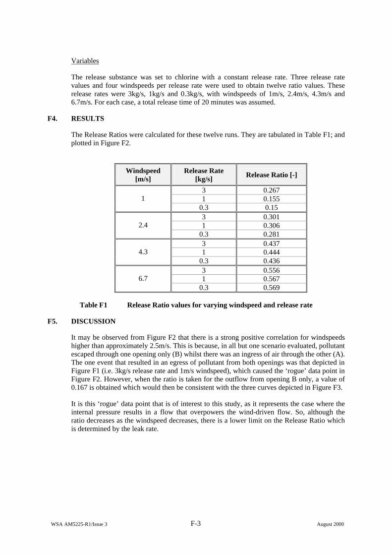
WSA AM5225-R1/Issue 3 F-3 August 2000
Variables
The release substance was set to chlorine with a constant release rate. Three release rate values and four windspeeds per release rate were used to obtain twelve ratio values. These release rates were 3kg/s, 1kg/s and 0.3kg/s, with windspeeds of 1m/s, 2.4m/s, 4.3m/s and 6.7m/s. For each case, a total release time of 20 minutes was assumed.
F4. RESULTS
The Release Ratios were calculated for these twelve runs. They are tabulated in Table F1; and plotted in Figure F2.
Windspeed [m/s]
Release Rate [kg/s] Release Ratio [-]
3 0.267 1 0.155 1
0.3 0.15 3 0.301 1 0.306 2.4
0.3 0.281 3 0.437 1 0.444 4.3
0.3 0.436 3 0.556 1 0.567 6.7
0.3 0.569
Table F1 Release Ratio values for varying windspeed and release rate
F5. DISCUSSION
It may be observed from Figure F2 that there is a strong positive correlation for windspeeds higher than approximately 2.5m/s. This is because, in all but one scenario evaluated, pollutant escaped through one opening only (B) whilst there was an ingress of air through the other (A). The one event that resulted in an egress of pollutant from both openings was that depicted in Figure F1 (i.e. 3kg/s release rate and 1m/s windspeed), which caused the ‘rogue’ data point in Figure F2. However, when the ratio is taken for the outflow from opening B only, a value of 0.167 is obtained which would then be consistent with the three curves depicted in Figure F3.
It is this ‘rogue’ data point that is of interest to this study, as it represents the case where the internal pressure results in a flow that overpowers the wind-driven flow. So, although the ratio decreases as the windspeed decreases, there is a lower limit on the Release Ratio which is determined by the leak rate.
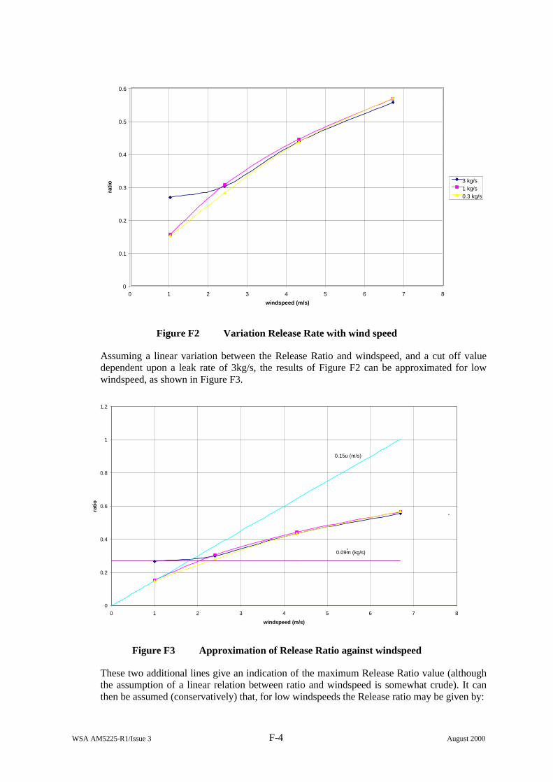
WSA AM5225-R1/Issue 3 F-4 August 2000
0
0.1
0.2
0.3
0.4
0.5
0.6
0 1 2 3 4 5 6 7 8
windspeed (m/s)
rati
o 3 kg/s1 kg/s0.3 kg/s
Figure F2 Variation Release Rate with wind speed
Assuming a linear variation between the Release Ratio and windspeed, and a cut off value dependent upon a leak rate of 3kg/s, the results of Figure F2 can be approximated for low windspeed, as shown in Figure F3.
0
0.2
0.4
0.6
0.8
1
1.2
0 1 2 3 4 5 6 7 8
windspeed (m/s)
rati
o
.
0.15u (m/s)
0.09m (kg/s).
Figure F3 Approximation of Release Ratio against windspeed
These two additional lines give an indication of the maximum Release Ratio value (although the assumption of a linear relation between ratio and windspeed is somewhat crude). It can then be assumed (conservatively) that, for low windspeeds the Release ratio may be given by:
WSA AM5225-R1/Issue 3 F-5 August 2000
( )m09.0,u15.0maxr &= (F.2)
where:
u = windspeed (m/s)
m& = leak rate (kg/s)
and the coefficients (0.15 and 0.09) are estimated from the curve.
Clearly, this can only sensibly be applied to u ≤ 6.7 m/s and m& ≤ 11 kg/s, since the Release Ratio cannot exceed 1.
F6. CONCLUSION
Although for higher windspeeds the average rate at which pollutant escapes from the room may be calculated via the Release Ratio approach, the clear correlation breaks down at lower windspeeds, at which there is a possibility of gas escaping from both leeward and windward openings. In these instances however, the Release ratio may be conservatively estimated by the maximum of 15% of the windspeed or 9% of the leak rate.
It should be noted that the calculations in this Appendix relate to a particular building volume and particular opening areas. Thus, whilst it gives a general indication of the Release Rates variation, it should be used with caution. Any specific building could be analysed in a similar way in order to determine the most appropriate parameters to be used. GRAB-T could also be used to determine the time-varying release rate, which could then be applied directly in the dispersion modelling in place of the Release Rates approach.

WSA AM5225-R1/Issue 3 F-6 August 2000
Printed and published by the Health and Safety Executive C1 02/01
CRR 324
£20.00 9 780717 619559
ISBN 0-7176-1955-9