Embed Size (px)
Citation preview

© 2018 Pella CorporationRevised 06/08/2018NF – 3
YOU WILL NEED TO SUPPLY: TOOLS REQUIRED:
• Moisture resistant shims/spacers
• Fasteners (see nail fin anchor instructions and tables at the end of this booklet)
• Closed cell foam backer rod/sealant backer
• Pella® SmartFlash™ foil backed butyl window and door flashing tape or equivalent
• Low expansion, low pressure polyurethane insulating window and door foam sealant DO NOT use high pressure or latex foams.
• Pella Window and Door Installation Sealant or equivalent high quality, multi-purpose sealant
• Tape measure
• Level
• Square
• Hammer
• Stapler
• Scissors or utility knife
• Small flat blade screwdriver
• Sealant Gun
• Screw Gun with a Phillips Driver bit
• 1/8" Allen wrench
SEALANTSEALANT
INSTALLATION WILL REQUIRE (2) OR MORE PERSONS FOR SAFETY REASONS.
A. Confirm the opening is plumb and level.NOTE: It is critical the bottom is level and it does not slope to the interior.
B. Remove dirt, oil or debris from the opening and surrounding wall surfaces.C. Confirm the window will fit the opening. Measure all four sides of the opening to make sure it is 1/2" to
3/4" larger than the window in both width and height. On larger openings measure the width and height in several places to ensure the header or studs are not bowed.NOTE: 1-1/2" or more of solid wood blocking is typically required around the perimeter of the opening. Fix any problems with the rough opening before proceeding.
D. For continuous exterior insulation panels up to 1" thick, utilize standard installation methods. For insulating panels 1.5" to 2" thick, Rough Opening Support Brackets or solid wood blocking is required.
DISCA
RD
PUSH
D
ISCARD
PU
SH
Shipping Clip
Pull screen nearshipping clip
A. Remove plastic wrap and cardboard packaging from window. DO NOT cut checkrail bands (if present) or remove plastic or foam shipping spacers located between the window sash and frame. DO NOT open the window until it is securely fastened.
B. Inspect the product for any damage such as cracks, dents or scratches. DO NOT install damaged windows.
C. Remove screens and hardware (if necessary). Label them and set them aside in a protected area. Windows with Half Screens: From the exterior, pull one side of the screen near the shipping clips until the
clips disengage from the frame. Rotate the shipping clips toward the exterior of the screen until they snap free from the screen.
Half screens of some vinyl windows can be removed from the interior.D. Fold out installation fin to 90° (units with fold up fin only).
Be careful not to remove or tear the fin corners.NOTE: If the fin is not at 90°, the window will not line up correctly on the interior.
E. Units with painted head drip cap fin and no pre-punched holes: Pre-drill holes through the fin (refer to the anchor page for spacing)
Curved top units with flexible fins: Prepare the window frame for attachment by pilot drilling through the frame or securing installation clips (refer to the anchor page).
Units with EnduraClad Exterior trim and narrow fins with NO pre-punched holes: Install clips or pre-drill holes for frame screws.
See the anchor instruction pages at the end of this booklet. Additional preparation may be required for performance upgrade, impact resistant products or to comply
with local building code requirements.F. Read the entire instruction before proceeding.
Interior
1A
Interior
1B
ROUGH OPENING VERIFICATION
PREPARE THE WINDOW FOR INSTALLATION
AB
2C
Fixed Extruded Fin
D
6“ from end
Lip
#6 x 5/8” corrosionresistant screws
2DE
E
Other construction materials may be required. Read and understand the instructions and inspect the wall conditions before you begin.
Store windows in upright position, out of direct sunlight.
PREPARING FOR NAIL FIN WINDOW INSTALLATION
These instructions were developed and tested for use with wall systems designed to manage water. These instructions are not to be used with any other construction methods or window frame types. Installation instructions for use with other construction methods or frame types may be obtained from Pella Corporation, your local Pella® retailer or www.installpella.com. Building designs, construction methods, building materials, and site conditions unique to your project may require an installation method different from these instructions and/or additional care. Determining the appropriate installation method is the responsibility of you, your architect, or construction professional.
Always read the Limited Warranty before purchasing or installing Pella® products. By installing this product, you are acknowledging that this Limited Warranty is part of the terms of the sale. Failure to comply with all Pella installation and maintenance instructions may void your Pella product warranty. See written Limited Warranty for details, including exceptions and limitations at pella.com/warranty, or contact Pella Customer Service at 877-473-5527.
NF – 3 NC_NFBW
© 2018 Pella CorporationRevised 06/08/2018NF – 6
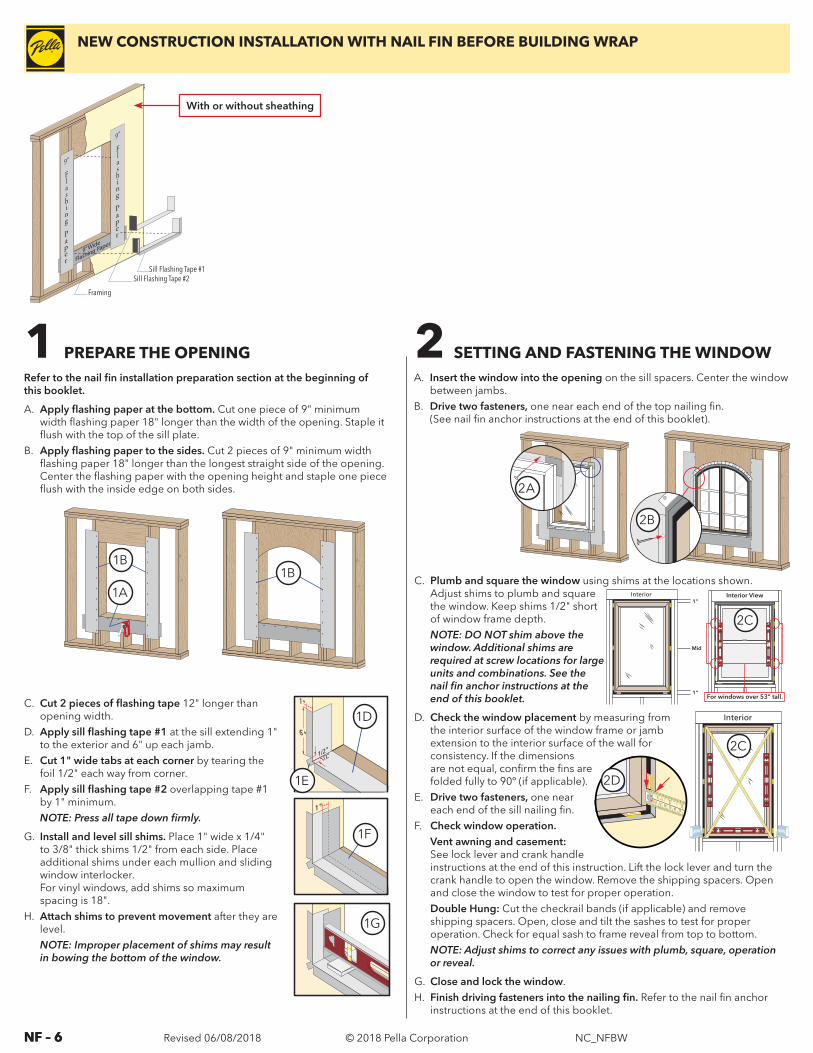
C. Plumb and square the window using shims at the locations shown. Adjust shims to plumb and square the window. Keep shims 1/2" short of window frame depth.NOTE: DO NOT shim above the window. Additional shims are required at screw locations for large units and combinations. See the nail fin anchor instructions at the end of this booklet.
D. Check the window placement by measuring from the interior surface of the window frame or jamb extension to the interior surface of the wall for consistency. If the dimensions are not equal, confirm the fins are folded fully to 90º (if applicable).
E. Drive two fasteners, one near each end of the sill nailing fin.
F. Check window operation. Vent awning and casement:
See lock lever and crank handle instructions at the end of this instruction. Lift the lock lever and turn the crank handle to open the window. Remove the shipping spacers. Open and close the window to test for proper operation.
Double Hung: Cut the checkrail bands (if applicable) and remove shipping spacers. Open, close and tilt the sashes to test for proper operation. Check for equal sash to frame reveal from top to bottom.NOTE: Adjust shims to correct any issues with plumb, square, operation or reveal.
G. Close and lock the window. H. Finish driving fasteners into the nailing fin. Refer to the nail fin anchor
instructions at the end of this booklet.
1 PREPARE THE OPENINGRefer to the nail fin installation preparation section at the beginning of this booklet.
A. Apply flashing paper at the bottom. Cut one piece of 9" minimum width flashing paper 18" longer than the width of the opening. Staple it flush with the top of the sill plate.
B. Apply flashing paper to the sides. Cut 2 pieces of 9" minimum width flashing paper 18" longer than the longest straight side of the opening. Center the flashing paper with the opening height and staple one piece flush with the inside edge on both sides.
C. Cut 2 pieces of flashing tape 12" longer than opening width.
D. Apply sill flashing tape #1 at the sill extending 1" to the exterior and 6" up each jamb.
E. Cut 1" wide tabs at each corner by tearing the foil 1/2" each way from corner.
F. Apply sill flashing tape #2 overlapping tape #1 by 1" minimum.NOTE: Press all tape down firmly.
G. Install and level sill shims. Place 1" wide x 1/4" to 3/8" thick shims 1/2" from each side. Place additional shims under each mullion and sliding window interlocker. For vinyl windows, add shims so maximum spacing is 18".
H. Attach shims to prevent movement after they are level.NOTE: Improper placement of shims may result in bowing the bottom of the window.
A. Insert the window into the opening on the sill spacers. Center the window between jambs.
B. Drive two fasteners, one near each end of the top nailing fin. (See nail fin anchor instructions at the end of this booklet).
1F
1"
1/2"
1/2"
6"
1E
1"
1G
2A
2 SETTING AND FASTENING THE WINDOW
Interior View
For windows over 53” tall.
Interior1”
1”
Mid
2C
12 0 3 0 4 0 5 0 6 0 7 0
23
INCHESmm
2D
Interior
2C
1D1B
1A
1B
1D
1E
1F
1G
2D2A
2B
9” Wide
Flashing Paper
Sill Flashing Tape #2Sill Flashing Tape #1
Framing
With or without sheathing
NEW CONSTRUCTION INSTALLATION WITH NAIL FIN BEFORE BUILDING WRAP
NF – 6 NC_NFBW
© 2018 Pella CorporationRevised 06/08/2018NF – 7
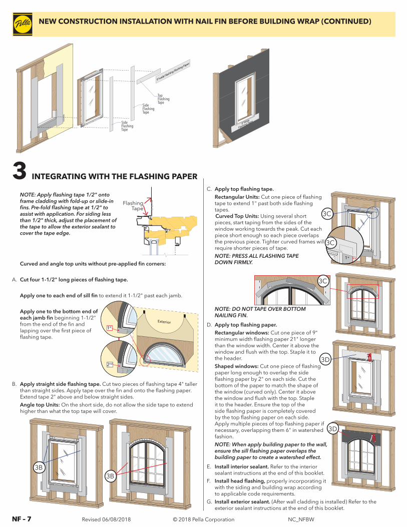
NOTE: DO NOT TAPE OVER BOTTOM NAILING FIN.
D. Apply top flashing paper. Rectangular windows: Cut one piece of 9"
minimum width flashing paper 21" longer than the window width. Center it above the window and flush with the top. Staple it to the header.
Shaped windows: Cut one piece of flashing paper long enough to overlap the side flashing paper by 2" on each side. Cut the bottom of the paper to match the shape of the window (curved only). Center it above the window and flush with the top. Staple it to the header. Ensure the top of the side flashing paper is completely covered by the top flashing paper on each side. Apply multiple pieces of top flashing paper if necessary, overlapping them 6" in watershed fashion.NOTE: When apply building paper to the wall, ensure the sill flashing paper overlaps the building paper to create a watershed effect.
E. Install interior sealant. Refer to the interior sealant instructions at the end of this booklet.
F. Install head flashing, properly incorporating it with the siding and building wrap according to applicable code requirements.
G. Install exterior sealant. (After wall cladding is installed) Refer to the exterior sealant instructions at the end of this booklet.
C. Apply top flashing tape. Rectangular Units: Cut one piece of flashing
tape to extend 1" past both side flashing tapes. Curved Top Units: Using several short pieces, start taping from the sides of the window working towards the peak. Cut each piece short enough so each piece overlaps the previous piece. Tighter curved frames will require shorter pieces of tape. NOTE: PRESS ALL FLASHING TAPE DOWN FIRMLY.
TopFlashingTape
SideFlashingTape
SideFlashingTape
9” wide Flashing Flashing Paper
Flashing Tape
3 INTEGRATING WITH THE FLASHING PAPER
NOTE: Apply flashing tape 1/2" onto frame cladding with fold-up or slide-in fins. Pre-fold flashing tape at 1/2" to assist with application. For siding less than 1/2" thick, adjust the placement of the tape to allow the exterior sealant to cover the tape edge.
Curved and angle top units without pre-applied fin corners:
A. Cut four 1-1/2" long pieces of flashing tape.
Apply one to each end of sill fin to extend it 1-1/2" past each jamb.
Apply one to the bottom end of each jamb fin beginning 1-1/2" from the end of the fin and lapping over the first piece of flashing tape.
B. Apply straight side flashing tape. Cut two pieces of flashing tape 4" taller than straight sides. Apply tape over the fin and onto the flashing paper. Extend tape 2" above and below straight sides.Angle top Units: On the short side, do not allow the side tape to extend higher than what the top tape will cover.
3B
1”
3B
3B3B
1st
2nd
3C
3C
3B3C
3D
3D
9” Wide 9” Wide
Flashing Tape
NEW CONSTRUCTION INSTALLATION WITH NAIL FIN BEFORE BUILDING WRAP (CONTINUED)
NF – 7 NC_NFBW

© 2018 Pella CorporationRevised 06/08/2018NF – 16
PLACE FASTENERS AT THE LOCATIONS INDICATED.
ProductPG
RatingMax Frame
Width (inches)
Max Frame Height (inches)
EdgeSpacing
(E)
Max. Intermediate
Spacing(s)
Anchor TypeAnchor Cluster
Wood *
Encompass and ThermaStar Windows
< 50 Any Any Every Other Pre-Punched 2" 11 Ga. Roofing NailAdditional nails at 3" and 6" on both sides of
the transition mullion at head and sill.
50 Any Any Every Pre-Punched Hole #8 x 2" Screw with Washer
** High Performance DH: (3) #10 x 2" jamb frame screws, 4" apart at checkrails. Use (4) #10 x 2" screws at head mullion ends and 4 clips at sill mullion ends 3" and 6" from
mullion.
25
0 S
ER
IES
Windows/CM/AW
< 50 Any AnyEvery Other Pre-Punched
Hole1.5" 11 Ga. Roofing Nail High Performance DH: (3) #8 x 2" jamb frame
screws, 4" apart at checkrails.SH/SW/FX 50 Any Any Every Pre-Punched Hole 1.5" 11 Ga. Roofing Nail
DH 50 Any Any Every Pre-Punched Hole #10 x 2" Screw with Washer ** 3 jamb frame screws, 4" apart at Checkrails.
CM/AW 50 Any Any Every Pre-Punched Hole #10 x 2" Screw with Washer None
Combinations < 35 Any AnyEvery Other Pre-Punched
Hole#8 x 2" Screw with Washer
(6) #8 x 2" screws at head mullion ends spaced 2" apart OR (4) #10 x 2" screws in
each end anchor.Combinations > 35 Any Any Every Pre-Punched Hole #8 x 2" Screw with Washer
35
0 S
ER
IES
SH and DH
30 40" 63" 6" 8" 1.5" 11 Ga. Roofing Nail None
40 40" 63" 6" 8" 1.5" 11 Ga. Roofing Nail 5 nails, 2" apart at Checkrails
+40/-60 Any Any 6" 8" 1.5" 11 Ga. Roofing Nail5 nails, 2" apart at Checkrails
and Mullion Ends
2-Panel Sliding
Windows
30 76" 48" 6" 8" 1.5" 11 Ga. Roofing Nail None
40 76" 62" 6" 8" 1.5" 11 Ga. Roofing Nail 5 nails, 2 inches apart Meeting Stiles
+40/-60 76" 72" 6" 8" #10 x 2" Screw with Washer 3 Screws, 2" apart at Meeting Stiles
3-Panel Sliding
Windows
30 123" 48" 6" 8" 1.5" 11 Ga. Roofing Nail None
40 123" 62" 6" 8" 1.5" 11 Ga. Roofing Nail 5 nails, 2" apart at Meeting Stiles
All Other Any Any 6" 8" #10 x 2" Screw with Washer 5 Screws, 2" apart at Meeting Stiles
CM/AW/FX40 Any Any 6" 8" 1.5" 11 Ga. Roofing Nail None
60 Any Any 4" 4" 1.5" 11 Ga. Roofing Nail None
FX Composites
All Any Any 4" 4" 1.5" 11 Ga. Roofing Nail 5 nails, 2" apart at Mullion Ends
ENCOMPASS BY PELLA®/THERMASTAR BY PELLA® / PELLA® 250 SERIES AND PELLA® 350 SERIES WINDOWS
* For light gauge steel framing, use #10 self-drilling modified truss head screws.
** High Performance Frame Fillers are required at each jamb anchor location.
NOTE: Do not over-drive fasteners, but allow for movement of building materials.
Refer to the supplemental instruction included with the unit for securing mullion end anchors (if applicable).
When screws are used in the Nail-Fin, a 1" fender washer is required at each screw anchor location.
Sliding Window XOX
Single-, Double-Hung Sliding Window XO / OX
E
E
E
S S E E EVERY
SEVERY
Casement
E
E
S S E E EVERY
SEVERY
E E S S EVERY
E
E
SEVERY
E E S S EVERY
E
SEVERY
Anchor clusters, see table.
Note: Standard performance only. Additional anchoring may be required for performance upgrade, impact resistant products or to comply with local building code requirements.
250 SERIES
SW Vent Track
HP Frame Filler
SW Pocket Filler
5/32" drill
3/8" drill for clearance hole
HP Nail Fin Frame with Frame Filler
Pocket Cover Removal
Attachment clip
Sill accessory groove
1/2”
1/2”
Attachment clip
3/8”
Clip Installation for Mullions
Plug
Drill (2) 5/32" holes and install (2) #10 x 1-1/2" screws per clip.
Self-adhesive spacer
NAIL FIN WINDOW ANCHOR INSTRUCTIONS
IMPORTANT: For installations over continuous exterior insulation, the anchor length must be increased by the thickness of the insulating panels
NF – 16 NC_NFBW
© 2018 Pella CorporationRevised 06/08/2018NF – 17
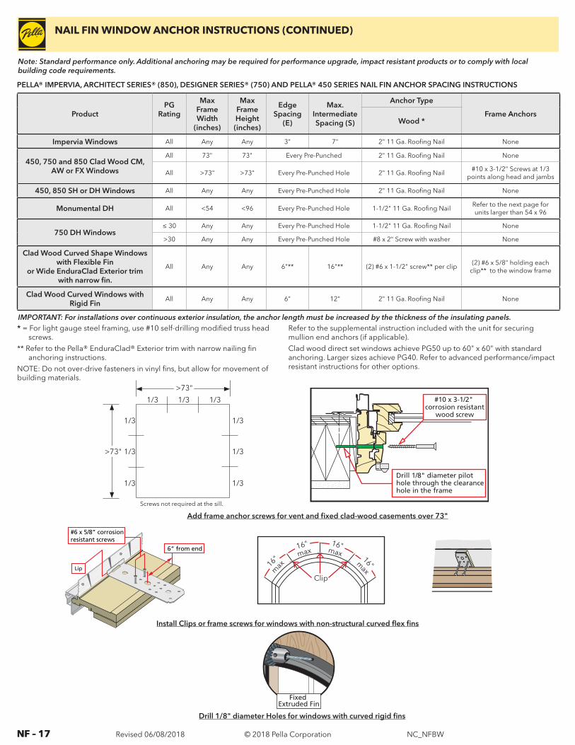
PELLA® IMPERVIA, ARCHITECT SERIES® (850), DESIGNER SERIES® (750) AND PELLA® 450 SERIES NAIL FIN ANCHOR SPACING INSTRUCTIONS
* = For light gauge steel framing, use #10 self-drilling modified truss head screws.
** Refer to the Pella® EnduraClad® Exterior trim with narrow nailing fin anchoring instructions.
NOTE: Do not over-drive fasteners in vinyl fins, but allow for movement of building materials.
Refer to the supplemental instruction included with the unit for securing mullion end anchors (if applicable).Clad wood direct set windows achieve PG50 up to 60" x 60" with standard anchoring. Larger sizes achieve PG40. Refer to advanced performance/impact resistant instructions for other options.
6“ from end
Lip
#6 x 5/8” corrosionresistant screws
16"
max
16" max
16" max
16" max
Clip
1/3 1/3 1/3
1/3
1/3
1/3
1/3
1/3
1/3
Screws not required at the sill.
>73"
>73"
Fixed Extruded Fin
#10 x 3-1/2" corrosion resistant
wood screw
Drill 1/8" diameter pilot hole through the clearance hole in the frame
Add frame anchor screws for vent and fixed clad-wood casements over 73"
Install Clips or frame screws for windows with non-structural curved flex fins
Drill 1/8" diameter Holes for windows with curved rigid fins
ProductPG
Rating
Max Frame Width
(inches)
Max Frame Height (inches)
EdgeSpacing
(E)
Max. IntermediateSpacing (S)
Anchor Type
Frame AnchorsWood *
Impervia Windows All Any Any 3" 7" 2" 11 Ga. Roofing Nail None
450, 750 and 850 Clad Wood CM, AW or FX Windows
All 73" 73" Every Pre-Punched 2" 11 Ga. Roofing Nail None
All >73" >73" Every Pre-Punched Hole 2" 11 Ga. Roofing Nail#10 x 3-1/2" Screws at 1/3
points along head and jambs
450, 850 SH or DH Windows All Any Any Every Pre-Punched Hole 2" 11 Ga. Roofing Nail None
Monumental DH All <54 <96 Every Pre-Punched Hole 1-1/2" 11 Ga. Roofing NailRefer to the next page for units larger than 54 x 96
750 DH Windows≤ 30 Any Any Every Pre-Punched Hole 1-1/2" 11 Ga. Roofing Nail None
>30 Any Any Every Pre-Punched Hole #8 x 2" Screw with washer None
Clad Wood Curved Shape Windows with Flexible Fin
or Wide EnduraClad Exterior trim with narrow fin.
All Any Any 6"** 16"** (2) #6 x 1-1/2" screw** per clip(2) #6 x 5/8" holding each
clip** to the window frame
Clad Wood Curved Windows with Rigid Fin
All Any Any 6" 12" 2" 11 Ga. Roofing Nail None
Note: Standard performance only. Additional anchoring may be required for performance upgrade, impact resistant products or to comply with local building code requirements.
NAIL FIN WINDOW ANCHOR INSTRUCTIONS (CONTINUED)
IMPORTANT: For installations over continuous exterior insulation, the anchor length must be increased by the thickness of the insulating panels.
NF – 17 NC_NFBW

© 2018 Pella CorporationRevised 06/08/2018NF – 18
E
E
E
EVERY
S
ESEVERY
M2
M1M1
M2
E
E
EVERY
S
M1
M2 M2
M1EE S S
EVERY
M1
M2 M2
M1S
SEVERY
E
E
SEVERY
SEVERY
E
S
M1M2
M2M1
SEVERY
E
EE
M1
M2
M2
M1
SEVERYE E
S
PLACE FRAME SCREWS OR CLIPS AT THE LOCATIONS INDICATED
ProductEdge
Spacing (E)
Max. Intermediate
Spacing (S)
First Mullion Anchor
(M1)
Second Mullion Anchor
(M2)
Fastener
Special NotesWood **
Casement / Awning 6" 16" 3"* 6"
#8 x 3" Finish Screw
Double- or Single- Hung 6" 16" 3"* 6"
#8 x 3" Finish Screw
Fixed Frame 6" 16" 3"* 6"#8 x 3" Finish
Screw
Monumental DH > 54" x 96" 6" (head) 16" (head) 3" * 6" * #8 x 3" Screw
Remove sashes and jamb liners. Drive 1 screw though each jamb liner support clip (top, bottom, checkrail and center of each sash). Drive 2 additional screws through the frame (or secure clips) 3" above and below the checkrail on each jamb. Drive additional screws through the frame (or secure clips) centered between each jamb liner support clip.
ARCHITECT SERIES® (850), DESIGNER SERIES® (750) AND PELLA® 450 SERIES WINDOW ANCHOR SPACING INSTRUCTIONS
* M1 anchor required if design pressure exceeds 20 psf.** For light gauge steel framing, use #10 self-drilling/self-tapping screws; For concrete or masonry, use 3/16" masonry
screws with 1-1/4" minimum embedment.
1/8" Pilot Hole Locations
Head
Jam
bSi
ll
Casement/Awning Designer/450 Series Double-Hung Architect Series Double-Hung Monumental-Hung
Do not install fasteners through operator cutout.
Pry Here
Sill anchors not required.
Designer Series
450 Series
Note: Standard performance only. Additional anchoring may be required for performance upgrade, impact resistant products or to comply with local building code requirements.
Units with narrow fins and NO pre-punched holes must be anchored using frame screws or installation clips. These fins are for flashing purposes only.
Units installed over continuous exterior insulation must be anchored using installation clips
6“ from end
#6 x 5/8” corrosionresistant screws
Lip
Exterior trim with narrow fin
UNITS WITH WIDE PELLA® ENDURACLAD® EXTERIOR TRIM WITH NARROW FINS AND NO PRE-PUNCHED HOLES ANCHOR INSTRUCTIONS AND MONUMENTAL HUNG > 54" X 96"
Monumental Hung jamb liner support clip
Pry off Monumental Double-Hung jamb liner
#6 x 1-1/2" screw
Clad Frame Head/Jamb/Sill
NF – 18 NC_NFBW

© 2018 Pella CorporationRevised 06/08/2018NF – 19
Interior Sealant InstructionsCAUTION: Use low pressure polyurethane window and door insulating foams. Follow the directions on the can. Do not use high pressure or latex foams.
A. Insert the nozzle or straw between the rough opening and window frame from the interior. Use a pliers (if necessary) to compress the end of a straw tube to allow it to fit in tight openings.
B. Place a 1" deep bead of foam approximately 1" from the interior of the frame to allow for expansion. DO NOT fill the entire depth of the rough opening cavity. NOTE: Apply foam between the frame and rough opening, NOT between jamb extensions and the rough opening.
C. To ensure a continuous interior seal, apply sealant over the interior surface of any shims or clips interrupting the foam seal. Backer rod (as necessary) and sealant can be used in place of the low expansion foam to create the interior seal. However, foam has greater insulating properties. Fiberglass batt or similar insulation is not recommended as it can absorb water and does not act as an air seal.NOTE: Use a low odor, paintable sealant such as Pella Window and Door Installation Sealant.
Re-check window operation and remove shipping spacers after foam installation. Excess foam may be removed with a serrated knife after it cures.
Exterior Sealant InstructionsCAUTION: Use a high quality, multi-purpose exterior sealant such as Pella Window and Door Installation Sealant. Follow the directions on the cartridge.
When applying siding, brick veneer , flashing, or other exterior finish materials, leave adequate space between the window frame and the material for sealant application.
A. Insert backer rod 3/8" deep in the space around the window. Backer rod adds shape and controls the depth of the sealant line.
B. Apply a continuous bead of sealant to the entire perimeter of the window.C. Shape, tool and clean excess sealant. When finished, the sealant should be the shape of an hourglass.
NOTE: The siding details below apply to windows without a J-mould as part of the frame. The J-mould frame is only intended for vinyl or metal sidings where the siding is extended behind the J-mould portion of the frame. The J-mould should be removed and replaced with backer rod and sealant with all other siding or trim types.
InteriorA
A
B
INTERIOR AND EXTERIOR SEALANT
SIDINGWITH TRIM
3/8" Clearance
InsulatingFoam
Perimeter Sealant must extend to roomside of Accessory Groove.
Accessory Groove
Sealant typical
3/8"Min.
3/8"
BRICK VENEER
3/8" Clearance
Backer Rod andSealant typical
Perimeter Sealant must extend to roomside of Accessory Groove.
Accessory GrooveInsulatingFoam
3/8"Min.
3/8"
SIDING
InsulatingFoam
1/8" Clearance
Sealant typical
AccessoryGroove
1/8"
NF – 19 NC_NFBW
© 2018 Pella CorporationRevised 06/08/2018NF – 20
Exterior Finish of Existing Frame (Pocket Replacement)It is the responsibility of the homeowner, contractor or installer to ensure any exposed unfinished wood is covered or finished. Possible methods include, however are not limited to, covering with aluminum coil stock or painting.
Cleaning InstructionsGLASS—Remove any protective film and labels and clean the glass, using a soft, clean, grit-free cloth and mild soap or detergent. Be sure to remove all liquid by wiping dry or use a clean squeegee.
Pella® ALUMINUM CLAD OR IMPERVIA FRAMES—The interior and exterior frame and sash are protected with a tough factory finish. Clean this surface with mild soap and water. Stubborn stains and deposits may be removed with mineral spirits. DO NOT use abrasives. DO NOT scrape or use tools that might damage the surface.
Notice: DO NOT use inappropriate solvents or brickwash or cleaning chemicals. If you do, permanent damage can result and the product failure, loss or damage would not be covered by the Limited Warranty.
Encompass by Pella®/Thermastar by Pella® and Pella® 350 Series Windows FRAMES—The vinyl frame may be cleaned using the same method as the glass. For stubborn dirt, a “non-abrasive" cleaner such as Bon-Ami® or Soft Scrub® may be used. Do not use solvents such as mineral spirits, toluene, xylene, naphtha or muriatic acid as they can dull the finish, soften the vinyl and/or cause failure of the insulated unit seal. Keep door tracks clear of dirt and debris. Keep weep holes open and clear of obstructions.
Interior Finish (Wood Windows)If products cannot be finished immediately, cover with clear plastic to protect from dirt, damage and moisture. Remove any construction residue before finishing. Sand all wood surfaces lightly with 180 grit or finer sandpaper. DO NOT use steel wool. BE CAREFUL NOT TO SCRATCH THE GLASS. Remove sanding dust. Pella products must be finished per the below instructions; failure to follow these instructions voids the Limited Warranty.
• On casement and awnings, it is optional to paint, stain or finish the vertical and horizontal sash edges.
• On single-hungs and double-hungs, do not paint, stain or finish the vertical sash edges, any finish on the vertical sash edges may cause the sash to stick; it is optional to paint, stain or finish the horizontal sash edges.
Note: To maintain proper product performance do not paint, finish or remove the weatherstripping, mohair dust pads, gaskets or vinyl parts. Air and water leakage will result if these parts are removed. After finishing, allow venting windows and doors to dry completely before closing them.
Pella Corporation is not responsible for interior paint and stain finish imperfections for any product that is not factory-applied by Pella Corporation. For additional information on finishing see the Pella Owner’s Manual or go to www.pella.com.
Care and MaintenanceCare and maintenance information is available by contacting your local Pella retailer. This information is also available at www.pella.com.
IMPORTANT NOTICEBecause all construction must anticipate some water infiltration, it is important that the wall system be designed and constructed to properly manage moisture. Pella Corporation is not responsible for claims or damages caused by anticipated and unanticipated water infiltration; deficiencies in building design, construction and maintenance; failure to install Pella products in accordance with Pella’s installation instructions; or the use of Pella products in wall systems which do not allow for proper management of moisture within the wall systems. The determination of the suitability of all building components, including the use of Pella products, as well as the design and installation of flashing and sealing systems are the responsibility of the Buyer or User, the architect, contractor, installer, or other construction professional and are not the responsibility of Pella.
Pella products should not be used in barrier wall systems which do not allow for proper management of moisture within the wall systems, such as barrier Exterior Insulation and Finish Systems (EIFS) (also known as synthetic stucco) or other non-water managed systems. Except in the states of California, New Mexico, Arizona, Nevada, Utah and Colorado, Pella makes no warranty of any kind on and assumes no responsibility for Pella windows and doors installed in barrier wall systems. In the states listed above, the installation of Pella Products in barrier wall or similar systems must be in accordance with Pella’s installation instructions.
Product modifications that are not approved by Pella Corporation will void the warranty.
For Casement Hardware Installation go to: www.installpella.com/trimaccessory/hardware
NF – 20 NC_NFBW