Embed Size (px)
Citation preview

Preparing repair capability of
ovens and water heaters for
Airbus A320 and A350 aircraft
Finnair Technical Services Ltd
LAHTI UNIVERSITY OF APPLIED SCIENCES LTD
Faculty of Technology Degree in Mechanical and Production Engineering Production Oriented Mechatronics Bachelor´s Thesis Spring 2017 Rudolf Silander

Lahti University of Applied Sciences Degree Programme in Mechanical and Production Engineering
SILANDER, RUDOLF: Preparing repair capability of ovens and water heaters for Airbus A320 and A350 aircraft
Finnair Technical Services Ltd
Bachelor’s Thesis in Production Oriented Mechatronics, 30 pages, 6 pages of appendices
Spring 2017
ABSTRACT
The aim of this thesis was to prepare and arrange all needed resources for Finnair Technical Services repair capability of Essence® Inserts Collection ovens and water heaters manufactured by B/E Aerospace. Finnair Technical Services was the mandator for this thesis.
The new model ovens and water heaters are being incorporated into the Finnair fleet and it has been seen beneficial to repair them in-house. These new components have been previously repaired at the manufacturer´s facility, but will be soon done internally.
Research objectives included test bench facility management, training coordination, document collection and control, procurement coordination and other project coordination related duties. Considering the explored subjects, this thesis could be thought to be widely multidisciplinary and educational for future work assignments.
All phases from ordering to implementation were to be studied, planned and managed, to ensure smooth flow throughout. Principles behind project management, work safety and functionality of components were explored as well.
The thesis created an information base for starting the repair operations of the mentioned ovens and water heaters.
Key words: Airbus, oven, project management, repair shop, user documentation, water heater

Lahden ammattikorkeakoulu Kone- ja tuotantotekniikan koulutusohjelma
SILANDER, RUDOLF: Airbus A320 ja A350 uunien ja vesikeittimien korjausvalmiuksien nosto
Finnair Technical Services Oy
Tuotantopainotteisen mekatroniikan opinnäytetyö, 30 sivua, 6 liitesivua
Kevät 2017
TIIVISTELMÄ
Opinnäytetyön tarkoituksena oli valmistella kaikki tarvittavat resurssit Finnair Technical Servicesille B/E Aerospacen valmistamien Essence® Insertions Collection -uunien ja -vedenkeittimien korjaustoiminnan aloittamiseksi. Toimeksiantajana toimi Finnair Technical Services.
Uuden malliset uunit ja vedenkeittimet ovat tulossa käyttöön ja niiden korjausvalmius on katsottu kannattavaksi suorittaa itse. Nämä uudet laitteet on aiemmin huollettu valmistajan korjaamolla ja tarkoituksena on tuottaa tämä palvelu sisäisesti.
Selvityksen kohteina olivat erityisesti testipenkin tilajärjestelyt, koulutuksien koordinointi, dokumenttien kerääminen ja hallinta, hankintojen koordinointi ja kaikki projektin koordinointiin liittyvät tehtävät. Tämän johdosta työtä voitiin pitää erittäin monialaisena ja opettavaisena tulevia työtehtäviä varten.
Kaikki työnvaiheet tilauksesta käyttöönoton jälkeiseen aikaan tarkasteltiin, suunniteltiin tai hallinnoitiin. Työssä tutkittiin myös projektinhallinnan, työturvallisuuden ja laitteiden toiminnallisuuksia perusteita soveltuvin osin.
Työllä saavutettiin tietoperusta edellä mainittujen uunien- ja vedenkeittimienkorjaamotoiminnan nostamiseksi.
Asiasanat: Airbus, korjaamo, käyttäjän dokumentaatio, projektinhallinta, uuni, vedenkeitin

TABLE OF CONTENTS
1 INTRODUCTION 1
2 BACKGROUND INFORMATION 2
2.1 Ovens 2
2.1.1 Convection 2
2.1.2 Steam 3
2.2 Water Heater 4
2.3 Component Count 5
2.4 Test Equipment 7
2.5 Workshop 9
2.5.1 Present 10
2.5.2 Future 11
3 PROJECT MANAGEMENT 12
3.1 Project Definition 12
3.2 Life Cycle of a Project 12
3.3 Risk Management 13
3.4 Identifying, Analyzing, Prioritizing and Controlling 13
3.5 Handling Chaos 14
4 PLANNING AND PREPARATIONS 17
4.1 Overall Project 17
4.2 Procurement 18
4.2.1 Spare Components and Parts for Components 18
4.2.2 Spare Parts for Test Bench 20
4.2.3 Tooling 20
4.3 Safety 20
4.4 Preventive Actions 20
4.5 Documentation 21
4.6 Listing Repair Capability 22
5 IMPLEMENTATION 23
5.1 Training 23
5.2 Facilities 24
5.3 Test Bench 24
5.3.1 Logistics 25

5.3.2 Calibration 25
6 CONCLUSION 26
6.1 Summary 26
6.2 Review 27
BIBLIOGRAPHY 28
APPENDICES 31

ABBREVIATIONS
ARINC Aeronautical Radio, Incorporated
ATA ATA 100 numbering system for aircraft documentation
CMM Component Maintenance Manual
FTS Finnair Technical Services Ltd
HMI Human Machine Interface
MOE Maintenance Organization Exposition
MTBF Mean Time Between Failures
MTTR Mean Time To Repair
OEM Original Equipment Manufacturer
RSPL Recommended Spare Parts List
SB Service Bulletin
SQMM Safety and Quality Management Manual
TOPI Technical Operations Procedures and Instructions

1 INTRODUCTION
This thesis was made for Finnair Technical Services Ltd (FTS), located at
Helsinki-Vantaa Airport. The subject for the thesis was mutually agreed
upon together with the company, as it was deemed necessary and
beneficial.
A new line of Essence® ovens and water heaters are slowly being
incorporated to the entire Airbus fleet, which creates a need for a new
repair capability.
FTS currently has line maintenance and components maintenance in three
hangars located at Helsinki-Vantaa Airport. The in-house repair capability
of the components discussed in this thesis are planned to be repaired in
the largest of them, hangar 7. The preceding models of these components
are repaired in the same room.
Formerly all Essence® line ovens and water heaters installed on Finnair
aircraft have been repaired at the manufacturer´s repair facility, at
Nieuwegein in the Netherlands. For the initiation period of in-house
repairs, it was decided to partially use the manufacturer´s repair facilities
to ensure no disturbances in flight operations and customer experience
due to the necessity of the equipment during flight.
Long experience of in-house repairs brings valuable knowledge when
preparing for this new line of components. Finnair has also been able to
collect valuable data on the reliability and common problems in the
components starting from the first Airbus A350 delivery in October 2015. It
is a good starting point for establishing in-house repair capability. All data
is retrieved from MRO production software called AMOS produced by
Swiss AS, which has all aircraft-related maintenance data Finnair needs.
The Essence® line has been chosen to be used on many current and
future A320 and A350- series aircraft that Finnair operates. At the moment
the line is only installed on A350-series, but later on it will be either
retrofitted or factory-installed on A320-series.

2
2 BACKGROUND INFORMATION
Here is gathered information of the components to be repaired, the
facilities and the test bench. Present and future workshop functions are
presented as well.
2.1 Ovens
Two types of ovens are used in aircraft convection and steam. Here is
presented the specific models that will be installed in most Finnair
operated aircraft. They will serve for a long period of time. Functionality is
also explored and visualized.
2.1.1 Convection
The convection type oven is DF3500-series oven and is manufactured by
B/E Aerospace. The oven can be seen in Image 1.
IMAGE 1. DF3500 Series Oven (B/E Aerospace 2017b, 1)

3
Forced convection is used in this specific case. It occurs when air is
heated and circulated via an integrated fan (Bahram 2015, 1).
To operate, both ovens use standard aircraft power 115V at 360-800Hz.
Unlike the steam oven, the convection type requires only a power source
to operate. (B/E Aerospace 2016a, 4)
All the presented products have an interface to connect it the aircraft
nervous system. The operation and status can be monitored through a
mobile application made by the manufacturer to ease use in the aircraft.
(Schlieske, 2017) A human machine interface (HMI) with a display is used
to control all functions of the ovens and view errors (B/E Aerospace
2016a, 8).
2.1.2 Steam
The steam oven is externally identical to the convection oven and is a
DS3500 -series oven. The image is left out due to similarity.
Internally the steam oven is slightly more complicated than the convection
oven. In addition to a power source, it requires a water source as well,
which makes it technically more complex than its counterpart. (B/E
Aerospace 2016b, 4) The water connection between the aircrafts galley
and the oven is produced by the ARINC 810 standard, which specifies
standard interfaces to be used in galley inserts (B/E Aerospace 2016, 10).
An image of the HMI is displayed on the next page.
Steam ovens are superior to the convection oven in two aspects, in
cooking quality and heat transfer. The moisture content and flavor of the
food are both preserved well, therefore creating a quality meal for
customers. Due to the steam, the heat transfer properties are improved
and lower cooking temperatures can be achieved. (Oslin 1994)

4
IMAGE 2. HMI Display and Buttons (B/E Aerospace 2016b, 12)
2.2 Water Heater
The water heater belongs to the same line of products as the ovens and
therefore is visually similar. It is a 4660-series water heater.
As with the steam oven, the water heater requires a power and water
source. Simplicity of function makes it technically more robust for example
IMAGE 3. 4660 Series Water Heater (B/E Aerospace 2017a, 1)

5
by means of a missing front control panel. (B/E Aerospace 2014, 1) The
heater is available in high and low tap models, both found in Finnair fleet.
Two tap models are required to enable installation into varying galley
shapes.
Operationally the water heater is much simpler than the ovens. It is
operated through a single button, whereas the oven has an HMI. The
water heater has a couple of indicators to indicate either readiness or an
error. (B/E Aerospace 2017a, 4)
An example of an installation configuration inside a Finnair aircraft is
presented below.
IMAGE 4. Photo of an Airbus A321 AFT Galley Configuration
2.3 Component Count
Total count of components installed on aircraft and stored as spares was
checked from AMOS-software at time of publishing the thesis. Aircrafts on
order and arriving with set components or being retrofitted were

6
considered when analyzing the future numbers. Steam ovens are not
installed on A320-series at all due to shorter hauls.
A350-series is configured as follows:
8 convection ovens
6 steam ovens
11 water heaters.
A320-series is configured as follows:
6 convection ovens
5 water heaters.
Having a harmonized component inventory throughout the majority of the
fleet brings several benefits. Once a spare inventory has been established
for the components, it will be applicable to a much broader component
count than having a diverse combination of components. It allows an edge
in inventory turnover rate.
Another advantage that is gained through the harmonized line of products
is reduced training requirements and complexity for flight crews and
technical personnel. Rather than having to attend trainings for each
varying line of products or manufacturer, all related personnel can attend a
much narrower range of trainings sessions. This will result in less training
required per person and increase familiarity to products in use.
As understanding and experience is gained, it could be thought to have a
positive effect on various areas, such as:
fault isolation
user related defects
unnecessary removal from aircraft.

7
2.4 Test Equipment
The test bench used is model CS 710-530 manufactured by AWL-
Techniek B.V. according to B/E Aerospace specifications. It is a double
test bench capable of testing two units at once. A picture of the test bench
is presented in Image 5.
IMAGE 5. CS 710-530 Test Bench (B/E Aerospace 2016c, 7)
The test bench is equipped to provide electricity, water and air pressure to
the operator. Key meters needed for testing can be found on a control
panel, including:
voltage
current
temperature
flow
water pressure.

8
The digital pressure meter for water is there to ensure sufficient input
pressure from the mains to both the steam oven and the water heater.
(B/E Aerospace 2016c, 16)
The control panel includes the main power connector, plug socket, temp
sensor and ESD connector. While testing, the main connector supplies
aircraft grade power to the component and the temp sensor will be used to
track the oven temperature development and function. The component
itself can run several tests, but also external computer software connected
via USB-cable can assist with fault isolation and testing. The computer
software is also used to upload and update the components (B/E
Aerospace 2016b, 11009).
Below are some labeled views of the control panel in Image 6 and switch
board in Image 7.
IMAGE 6. Front view of control panel (B/E Aerospace 2016c, 16)
Location of the switch board has been modified from the previous design,
from beneath the control panel to the front of the working surface. This
was done for customer convenience. (Schlieske 2017)

9
IMAGE 7. Switch board (B/E Aerospace 2016c, 17)
On the 23rd of February 2017, a one-day excursion was made to B/E
Aerospace Netherlands Nieuwegein repair workshop to see the test bench
in action. This workshop handles ovens and water heaters of many
European customers, including FTS at the time of publishing. Meeting B/E
Aerospace personnel in person was truly helpful as a great deal of
interaction was required during the thesis process. Overall, the excursion
gave many practical insights and a short video was filmed to be shown to
FTS mechanics.
2.5 Workshop
Up to date, Finnair has had capability for all its ovens and water heaters
installed on its Airbus fleet. The long experience has refined operations to
well suit the entire fleet. The retrofits to A320-series and factory
installations to A350-series, will not affect the total amount of units
circulating drastically at first. The old A340-series, and later A330-series,
will all be replaced by a total of 19 aircraft from the A350-series.
The personnel working in the workshop have a long solid experience with
aircraft components and are easily trainable for new ones. The persons
chosen for training have been working with the preceding models of the
components.

10
2.5.1 Present
The layout of the current workshop has been planned well, but minor
changes will be made to accommodate the new test bench. As other
sensitive electrical components are currently being repaired in the same
room, they are to be moved to an isolated room close by. This will help to
keep different type components separate, especially from the water
needed to test the ovens and water heaters.
IMAGE 8. Photo of the current test bench at the workshop
The functionalities are fairly similar to the existing ones, but updated to
current standards and requirements. Image 8 above presents the current
test bench with additional equipment on-top.

11
2.5.2 Future
Once the test bench is set up and all personnel is trained, Finnair will have
an efficient and updated workshop ready to serve both in-house and
external repair needs. To ensure future competitiveness and quality, FTS
will monitor the mean time between failures (MTBF), mean time to repair
(MTTP) and repair costs. Components will still be sent for external repair
to the manufacturer from time to time to benchmark FTS operative
success and quality in repairs.
The facility that will enclose the workshop consists of several working
benches, a chemical treatment room and the final test bench. With this
configuration, it is possible to have multiple units in repair simultaneously
and still maintain cleanliness and order during operations.

12
3 PROJECT MANAGEMENT
In this section, project management, project life cycle and further details of
projects will be explored. Especially risk management and approaches to
cope with unforeseen events are looked into. In a risky and competitive
environment, such as the aviation industry, it is valuable to recognize and
analyze these conditions in order to effectively deal with them.
3.1 Project Definition
A project can often be defined by the characteristics presented here
(Paasivaara, et al 2008, 7-8):
unique and definite task
pre-defined scope of work
set objective.
In general, projects are non-routine tasks that are aimed at a specified
problem, improvement requirement or implementation of something new.
One of its strengths is the fact that it can be aimed accurately at each task
needing attention, enabling focus on one rather than a group of tasks. This
requires giving each individual project a proper context and thorough
examination to succeed. (Paasivaara, et al 2008, 8):
3.2 Life Cycle of a Project
Each project, whether short or long, has a life cycle. They can be divided
into multiple phases, of which a five-phase life cycle is presented here
below (Paasivaara, et al 2008, 103):
recognizing the necessity
planning and initiation
experimentation and implementation
closing and assessment of effectiveness
handing over and integrating the project outcome to its function.
13
3.3 Risk Management
With all projects and operations there are risks that may compromise or
delay the desired end-results. It is always good practice to map all risks
that can be identified beforehand and minimize their effects. Sometimes
unexpected risks can arise and they have to be dealt with ad hoc.
(Karlsson & Marttala 2001, 130-131) In this project for example a sudden
change of the chosen facility or major delivery problems could both result
in delays of the workshop initiation.
Here are explored the detected risks and guidelines how to manage them.
3.4 Identifying, Analyzing, Prioritizing and Controlling
Various ways of categorizing risk sources have been identified, of which
some common ones are listed below (Artto, et al 2006, 205):
external
internal
communication
decision making
human factors
unforeseen events
project adjacent factors
complications in coordination.
Due to the uniqueness of each project, each one has to be assessed
separately and with creativity when predicting risks. Project management
experience can bring certain benefits to recognizing risks. However,
diverse views are required to get a comprehensive idea. It may also
benefit the overall team spirit, help to motivate and enhance the focus of
the project participants. (Artto, et al 2006, 204-205)
In this project, the risks were first assessed superficially based on prior
knowledge of the author and later assessed together will all participants.
14
This brought contrast between views and helped realize why it is important
to have as many people involved as possible.
A risk assessment matrix was prepared to display identified risks together
with their probability, impact and preventive actions. It can be found in
Attachment 4. (Karlsson & Marttala 2001, 130-131) The matrix provides
risk assessment from all phases up to the date of workshop initiation.
3.5 Handling Chaos
Even if a team consisting of the world´s leading experts, project managers
and employees were put together, things can still go horribly wrong. To
completely avoid this, there is no other option than to either not participate
in such projects or to only choose risk-free projects. The problem is that
this attitude hardly ever spawns successful projects or project managers.
(Berkun 2006, 272)
It requires a certain type of knowledge to understand that after things have
gone wrong, they cannot be undone. So, it can be thought to be crucial for
the project's success to have a team that can overcome the problems and
find solution effectively. (Berkun 2006, 272) Personally having noticed this
as well, it gives greater motivation to help others comprehend and cope in
tough situations. Here below is a quote to help bring self-awareness in
problem solving:
You can blame people who knock things over in the dark or you can start lighting candles. You are only at fault if you know about a problem and choose to do nothing.
-Paul Hawken (Berkun 2006, 272)

15
Here are a few general steps to apply when facing difficult situations
(Berkun 2006, 273-275):
Calm down.
Asses the problem in respect to the project.
Keep yourself calm.
Assemble the right people.
Explore the options.
Come up with a simplistic plan.
Execute the plan.
Organize a debriefing of the situation afterwards.
Although theories and visuals of project management might give a general
understanding on how to cope with difficult situations, the only way to
master them is to learn through practical simulations together, with trial
and error. It has to be kept in mind that it is a long process and cannot be
learned overnight. It is also important to do a post-analysis of what were
the root causes and what improvements to make for the next time. (Berkun
2006, 281)
Before plunging into the real world and problems, it is beneficial to
recognize when you in fact are in a tough situation. Presented below are a
few common characteristics of how to recognize one (Berkun 2006, 277):
There is a gap between reality and the current plan that needs
urgent attention.
It is unclear where the gap is, what caused it and whose job it is to
solve or whether it is even there.
It is unclear what resources should be used to fill the gap. Also,
there might be a fear that taking initiative or doing nothing will make
things worse.
Through personal experience, it can be noted that the times something
has failed or gone wrong are the ones that can be recalled with ease.

16
At the time of occurrence, the situations have been recognized and
researched thoroughly for future occurrences. This has led to a much
deeper learning experience and overall situational awareness.
Minimizing the damages the problems might cause has to be given some
thought. Once an unforeseen urgent problem arises, there might not be
time to research and ponder it in depth, but it requires immediate actions
to be taken. Good examples are astronauts and pilots when confronted
with a serious problem. They have to start diagnosing and isolating the
problem systematically through a procedure manual. Procedure manuals
may not be available for the projects manager and therefore it is advised
to have guidelines on how to proceed efficiently. (Berkun 2006, 284-286)
A guideline is presented below in Image 9 with steps to help with
minimizing damages in urgent problematic situations.
IMAGE 9. Minimizing Damages (Berkun 2006, 285-286)

17
4 PLANNING AND PREPARATIONS
This section will discuss measures and phases that must be considered
before the implementation stage of the project. Overall project success
and on-time initiation of the workshop depend highly on this stage.
4.1 Overall Project
Before the workshop can be initiated and the first authorized release
certificate given to a part, multiple internal preparations relating to aviation
regulations are required. A comprehensive evaluation of tooling, spares,
personnel and facilities is to be made and compared to the requirements
set forth by the CMM and manufacturer. A considerable factor is the scope
of work to be performed, which is required to be defined. For example, a
defined work scope of overhaul or bench test require entirely different
resources. These components are removed only when faulty and they
require repair.
A widely use planning and scheduling technique is called Gantt -chart.
Dividing the project into tasks and sub-tasks makes it easier to monitor the
progress of the project and keep track of planned versus realistic
workload. (Paasivaara, et al 2008, 108) One shall be prepared to track the
remainder of the project. Below, in Image 10, is an example of a Gantt -
chart. Additional information can be added to columns, such as:
start and end-date
responsible person
resource needs.
IMAGE 10. Example Gantt Chart (Paasivaara, et al 2008, 107)
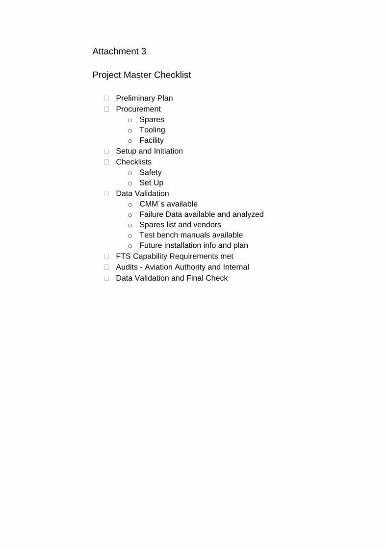
In Attachment 3, a supporting checklist can be found.
18
4.2 Procurement
To successfully operate a workshop, it is required to have a sufficient
spare part inventory, as well as proper tooling to be able to complete
repair and maintenance tasks on any components in a timely manner.
Here is explored the different procurement needs and guidelines on how
they will be fulfilled.
4.2.1 Spare Components and Parts for Components
Ensuring minimal operational disruptions and maximal customer
satisfaction is one of the core goals of FTS. It is required to have a
sufficient component inventory together with optimal turn-around-times for
repairs. Calculating the annual demand of spare components is a key
contributor and therefore it is vital to do so. The formula used to
accomplish this is similar to the one presented below in Formula 1:
In which "Da" represents annual demand, "FH" flight hours per aircraft per
yer, "FS" number of aircraft in the specified period, "QPA" quantity per
aircraft and "MTBUR" mean time between unscheduled removals. The
term "MTBUR" can be calculated from the formula below in Formula 2:
Where "Rus" represents the number of unscheduled removals during that
period and others as mentioned previously. These calculations will be
performed during the project.
Together with the components, the manufacturer has provided
recommended spare parts lists (RSPL) that identify a set of parts
recommended to be available during workshop activities. An RSPL for only
𝐷𝑎 =𝐹𝐻 ∗ 𝐹𝑆 ∗ 𝑄𝑃𝐴
𝑀𝑇𝐵𝑈𝑅
FORMULA 1 Calculating Annual Demand of Spares (SAP 2017)
𝑀𝑇𝐵𝑈𝑅 =𝐹𝐻 ∗ 𝑄𝑃𝐴
𝑅𝑢𝑠
FORMULA 2 Calculating MTBUR (Carroll 2005)

19
line maintenance activities was provided as well, but the workshop level
RSPL is more detailed and better suited for the planned operations.
Due to the volume of parts listed on the RSPL, it must be thoroughly
analyzed before a decision is made on which parts are economically and
operationally wise to procure. During analysis, it is expected that some
parts might already be available in stock because of on-going workshop
operations with preceding ovens and water heaters. The manufacturer of
the currently repaired components is the same and therefore it is
reasonable to expect some similarities in parts, especially standard issue
parts.
In today’s world, inventory turnover must be monitored carefully. It is
essential for a company´s success not to have capital fixed to an inventory
which has low turnover. (Sakki 2001, 156) FTS is currently using supply
chain management software, synchronized with AMOS, to manage and
optimize its inventory. Especially in the aircraft maintenance industry, lead
times of parts vary greatly, in worst cases to over 120 days, but at the
same time the parts might be essential to operating the aircraft. These two
programs play a key role in assisting in finding harmony between parts
availability and inventory turnover management.
To assist with the analysis, information on used parts was gathered from
all shop reports available in the production software AMOS. The listed
parts indicate commonly failed parts and reasons leading to scrapped
parts. Although most shop reports were from warranty orders, they still had
the information available.
After a decision has been made on parts to be procured, an order will be
placed with the manufacturer and followed up to ensure on-time delivery.
Based on current knowledge, the workshop might be initiated by the end-
of 2017 and therefore it is recommended to have procurement lists ready
not later than the end-of May 2017. Should the schedule change, an order
is recommended to be made a minimum of 120 days in advance.

20
4.2.2 Spare Parts for Test Bench
A spare parts list is available for the test bench, but it was decided that
parts will be purchased on an ad hoc basis due to commercial availability.
Also, the ability to utilize existing test benches via adapters creates a
back-up for any defects that may arise with the new test bench.
4.2.3 Tooling
The CMM provides a comprehensive list of tooling required to complete
workshop activities. In addition to hardware, some software is required as
well and therefore a computer needs to be integrated on top of the test
bench. (B/E Aerospace 2016b, 1003) An evaluation of needed tools
versus existing ones will be made during the months following the
completion of this thesis. Preceding components have not been digitally
advanced and therefore software has not been required before.
4.3 Safety
Safety comes first in any work situation and therefore great emphasis is
put on it. Every day the goal is to return home safely and go to work
without feeling afraid of something happening. Here is explored how we
can achieve this goal and other safety measures that must be taken into
account.
4.4 Preventive Actions
Finnair has a Safety and Quality Management Manual that lays down a
Just Culture and the general line for safety. Safety must be implemented
at an organizational level, not just as each individual´s own responsibility.
The Just Culture enables finding root causes and preventing future
occurrences without shifting blame. It is also possible to freely report
safety issues and openmindedly discuss them for the benefit of everyone.
(Finnair Plc 2017b)

21
Proper safety gear has always been easily accessible to all personnel
working in conditions requiring protection. By observing current operations,
it can be noted that safety measures are followed well. With the oven and
water heater a few risks are present, but by following instructions and
having awareness of the job at hand can go a long way in preventing
them. Here below are presented the easily noticeable risks:
chemical contact
falling object on body part
minor scratches from sharp edges
presence of hot parts during and after test cycles
presence of electricity and water.
Warnings included in the CMM and common awareness help to prevent
these unpleasant incidents. To ensure that the project itself has safety
nets to implement safety on its part, a check list including safety related
aspects was prepared. It may be found in Attachment 1. It was prepared to
assist the tracking of safety items. (Robinson & Choudhuri 2011, 6)
4.5 Documentation
Here are listed documents that have to be gathered before starting
operations:
CMM´s for each component part number
user manual for components
user manual for test bench
calibration manual for test bench
spares list for components and test bench
certificate of conformity for test bench
training certificates from manufacturer
CE-certificate.

22
4.6 Listing Repair Capability
All components, that are to be repaired under the company´s EASA Part
145 license, must be listed in the capability list. The MOE of the company
specifies what information is required for a component to be listed on the
capability list. Current listing holds more than 800 individual part numbers.
(Finnair Plc 2017a)
Here below is listed information needed for each part number according to
MOE (Finnair Plc 2017a, 21):
manufacture part number or model number including the dash-number
description
manufacturer
ATA chapter
scope of capability
overhaul, repair, inspection and/or testing
responsible work shop
category in accordance with EASA Part-145 approval (C1-C20)
date of incorporation to the list or date of last amendment of the scope of the work.
Additionally, the following information is required to maintain the repair
capability and future compliance with all applicable requirements (Finnair
Plc 2017a, 21):
current manufacturer maintenance data or other CAA FI acceptable specification
trained and authorized personnel
appropriate facilities
required equipment and tools (an opportunity to lease tool or
equipment when needed shall be demonstrated to the authority by
letter of intent or by other means).
According to procedures a FTS standard capability list amendment form
1051 will be filled in and signed by the production manager. After all
requirements and the form have been fulfilled it is possible to start
operations. (Finnair Plc 2017a, 21): The forms will be completed during the
project.

23
5 IMPLEMENTATION
This thesis will be completed before the actual hardware needed to set up
the workshop has arrived and therefore great effort is put into describing
and analyzing each phase in depth to ensure a smooth start of operations.
5.1 Training
For both components, B/E Aerospace will arrange separate training at
different locations. The product and maintenance training for the oven will
be held in Nieuwegein, Netherlands, and for the water heater in Lenexa,
USA. Training will be held in two separate locations, as it will provide the
best training results. (Schlieske, 2017) It was seen beneficial for Finnair to
have me attend both training sessions later this year together with the
attending mechanics. It enables me to understand the component in depth
and give minor engineering support to production when necessary.
Attendance to training will be arranged in groups to ensure uninterrupted
flow in production. It is also seen optimal to attend the trainings after all
annual leaves have been held in the summer. This will also give a
possibility for mechanics to try out the test bench before attending training
and come up with any questions related to use.
According to EU directive 2006/42/EY, if a machine is seen to require
training for safe use, the manufacturer shall arrange some form of
familiarization or instruction to ensure this. A fully comprehensive training
is not expected, but a training enabling safe use of the machine. (The
European Parliament and Council 2006/42/EC 2006) In this case, the
training discussed is mainly for product and maintenance. However, it will
include usage of the test bench and therefore could be thought to cover
safe use of the test bench. A certificate will be issued by the manufacturer
for each participant completing the training.

24
5.2 Facilities
The existing workshop handling preceding components has made the
facility capable of housing the new test bench with minimal modifications,
allowing cost-efficient adaptation for the successive components. The
main requirements are (B/E Aerospace 2016c, 13):
115V 400Hz aircraft power
230V 50Hz standard power
internet connection
water supply
air pressure supply
drainage.
All these can be found in existing test benches in the same room. The only
task is to run the existing connections to where the test bench will be
installed. This will be done by the standard facility management company
outsourced by FTS.
Should changes to the chosen location of the workshop arise later in the
project, they will be dealt with within the guidelines discussed in the project
management section of this thesis. This is due to the fact that the changes
will be unforeseen and will also affect other operations present at the
current location. It can be considered to be a major risk to the schedule if
the facility is later on decided to be established in another location. Further
risk assessment, with possible preventive actions, can be found in
Attachment 4.
5.3 Test Bench
The test bench is scheduled to arrive after 28 July 2017 per current
information received from the manufacturer. Slight delays will not have
considerable effects as the training will be held from October 2017
onwards. After the arrival of the test bench, it will be set-up as per
instructions and a comprehensive deployment inspection will be made.

25
Set-up instructions are required in the user manual of the test bench (The
European Parlament and Council 2006/42/EC, 2006). The employer is
required by law to do a deployment check and scheduled checks to
ensure safety of the equipment at all times (Occupational Safety and
Health Act 738/2002, 43§). FTS has a form 3035 for completing the
deployment inspection as described in the MOE Part 2.4 (Finnair Plc
2017a, 13).
5.3.1 Logistics
The test bench will be shipped in a specially designed crate. The FTS
logistics department has decades of experience shipping aircraft goods to
and from Europe. The shipment of the test bench will not pose a great
challenge. Once it arrives at Finnair facilities it will be opened and moved
to the workshop. The elevator inside the hangar will be able to lift the test
bench to the workshop located on an upper floor. Measurements were
made to ensure that the test bench can be maneuvered to its final location
(AWL-TECHNIEK B.V. 2015) The only risks posed are improper handling
during transportation or poor packaging. Having shipped many units
before, the manufacturer has ensured their shipping crate is capable of
safe transport of the test bench (Schlieske 2017).
5.3.2 Calibration
For procedures and data required for calibration, the B/E Aerospace User
Manual Calibration Procedure must be used. As per manufacturer's
manual and internal manuals calibration is required at an annual interval.
The test bench will arrive readily calibrated and must be calibrated next in
late 2018. Per previous knowledge and calibration procedures, the
calibration itself should take no more than one working day to complete
and can be done on site. (B/E Aerospace 2013)

26
6 CONCLUSION
The thesis was successfully finished on time and the desired state to
continue further along the project was achieved. Knowledge and
resources gathered during the making will help in the next phases and
until initiation of the workshop. In these last sections, a summary and a
review of the thesis process and project will be looked into.
6.1 Summary
Starting this thesis and the project was exciting event and it was truly a
great learning experience. Without much prior experience of projects or
their management, it was clear almost everything would be new. It was
motivating to research the world of project management; especially
studying how to manage conflicts and unforeseen events was thought-
provoking.
Although working in high pressure conditions and a hectic environment is
familiar, the ability to handle these tough situations has been a weakness
and quite unknown so far. Now that a solid knowledge base has been set,
the learning experience will continue as new situations are faced. It is
beneficial to keep a learning mindset in the future and keep on top of
current knowledge as well.
Preparing the repair capability will continue as specified in the thesis
together will all related groups. FTS procedures from MOE and TOPI
together with other applicable laws, will be followed to ensure compliance
with aviation regulations and safety in every aspect.
At the time of publishing the thesis it is estimated that the workshop will be
fully functional during the year 2017. Great effort will be put into meeting
this goal.

27
6.2 Review
Continuous learning and improvement in any task requires awareness of
the whole process and the end result. Enhancing performance for the next
round of tasks requires evaluation and reflection of the performed tasks.
Meeting the evaluation criteria set for the thesis was also a goal to be
achieved.
Theoretical background data and documentation was successfully
harvested. The big picture was well perceived and a solid base was
created to continue with the project management. Also, valuable
connections, both internally and externally, were made to assist with each
phase of the project. It was challenging at first, due to a new working
environment, but thanks to an open and supportive atmosphere it was
manageable. Active cooperation and interaction has to be maintained with
all parties to address both positive and negative subjects that may arise. A
more precise grip on scheduling and managing meetings is required for
the remainder of the project.
A rigorous familiarization with the thesis guidelines assisted in writing it
efficiently. Having all appropriate resources at hand and knowing how to
utilize them, was the key to being efficient. Albeit a firm schedule was not
prepared, excluding the deadline, a preliminary plan and adaptive
scheduling worked well during the process. As mentioned earlier, a
specific plan will be prepared to track the rest of the project.
New and challenging things can often require leaving one´s comfort zone,
but doing so is rewarding and educational. This requires a modern, multi-
disciplinary and versatile work place, which FTS has proven to be. It is a
pleasure to learn and implement the knowledge in such an environment.

28
BIBLIOGRAPHY
Artto, K., Martinsuo, M. & Kujala, J. 2006. Projektiliiketoiminta. Helsinki:
WSOY.
AWL-TECHNIEK B.V. 2015. Main Assembly Dubbele Testbank CAD
Drawing No T178452
B/E Aerospace. 2013. Test Bench Calibration Procedure. Nieuwegein.
B/E Aerospace. 2014. 4660-Series Water Heater Component Maintenance
Manual. Lenexa.
B/E Aerospace. 2016a. DF3500 Convection Series Oven Component
Maintenance Manual. Nieuwegein.
B/E Aerospace. 2016b. DS3500 Steam Series Oven Component
Maintenance Manual. Nieuwegein.
B/E Aerospace. 2016c. User Manual Test Bench CS 170-530.
Nieuwegein.
B/E Aerospace. 2017a. Operation Manual 4660 Water Heater.
B/E Aerospace. 2017b. Operation Manual DF3500 Convection Oven.
Bahrami, M. 2015. Forced Convection. [Accessed 2 April 2017].
Available at:
http://www.sfu.ca/~mbahrami/ENSC%20388/Notes/Forced%20Convection
Berkun, S. 2006. Projektihallinnan Taito. 1st ed. Helsinki: Readme.fi.
Carroll, T. 2005. The Fallacy of MTBUR & MTBF as Reliability Metrics.
[Accessed 7 April 2017].
Available at:
http://www.sae.org/events/dod/presentations/2005tomcarroll.pdf

29
Finnair Plc. 2017a. Maintenance Organization Exposition Rev. 1. Vantaa.
Finnair Plc. 2017b. Safety and Quality Management Manual Rev. 7.
Vantaa.
Karlsson, Å. & Marttala, A. 2001. Projektikirja. 1st ed. Helsinki: Talentum
Media Oy.
Ministry of Social Affairs and Health. 2002. Occupational Safety and
Health Act No. 738/2002, 43§. [Accessed 19 March 2017].
Available at: http://www.finlex.fi/fi/laki/ajantasa/2002/20020738
Oslin, R. G. 1994. Steamer apparatus US 5368008 A Grant. [Accessed 12
April 2017].
Available at: https://www.google.com/patents/US5368008?hl=en
Paasivaara, L., Suhonen, M. & Nikkilä, J. 2008. Innostavat projektit. 1st
ed. Helsinki: Suomen sairaanhoitajaliitto ry.
Robinson, N. & Choudhuri, A. 2011. Bridging Industry Best Practices in
Project Management and Safety Assurance to Academic Propulsion
Research. San Diego, 47th AIAA/ASME/SAE/ASEE Joint Propulsion
Conference & Exhibit.
Sakki, J. 2001. Tilaus-toimitusketjun hallinta. 5th ed. Espoo: Jouni Sakki
Oy.
SAP. 2017. Parameters used in the Spare Parts Stock Calculation.
[Accessed 7 April 2017].
Available at:
https://help.sap.com/saphelp_dimp50/helpdata/en/23/e67674c3e3477b89
3fb48ec13a3c48/content.htm
Schlieske, T. 2017. Product Support Engineer. B/E Aerospace
Nieuwegein. [Interview] (23 February 2017).

30
The European Parlament and Council 2006/42/EC. 2006. Machinery
Directive 2006/42/EC of the European parliament and of the Council.
Official Journal of the European Union.

31
APPENDICES
Attachment 1: Safety Checklist
Attachment 2: Set-Up Checklist
Attachment 3: Project Master Checklist
Attachment 4: Finnair 3035 Form Koneturvallisuustarkastuspöytäkirja
Attachment 5: Risk Assessment Matrix
Attachment 6: Finnair 1051 Form Capability List Amendment

Attachment 1
Safety Checklist
Safety instruction sheet available in Finnish (Turvaohjeet)
CE- label found on test bench
Machinery Directive -Certificate of Conformity for test bench
(2006/42/EC)
EMV-Directive -Certificate of Conformity for test bench
(2006/30/EC)
Low Voltage Directive -Certificate of Conformity for test bench
(2006/95/EC)
Test bench and product user training by manufacturer
Finnair internal risk assessment completed
Preliminary inspection and test before use, documented
Connect ESD between test bench and ground, verify continuity
All safety related documentation archived digitally and physically

Attachment 2
Set-Up Checklist
Unpack the test bench from shipping crate
Inspect completed for possible damages
Navigate the test bench to designated installation location
Clear and clean installation area
Place test bench on spot and adjust to height
Connect 3x 115V 400Hz to power supply
Connect 1x 230V 50Hz to switch board
Water connection to water supply
Air connection to air pressure supply
Place the PC on the test bench as planned, make all needed
connections and setups required for use
Connect ESD between test bench and ground, verify continuity
Drainage connection to sewage line
Place PVC/Teflon protector plates on test bench table and fasten
Complete preliminary inspection and test, with documentation
Attachment 3
Project Master Checklist
Preliminary Plan
Procurement
o Spares
o Tooling
o Facility
Setup and Initiation
Checklists
o Safety
o Set Up
Data Validation
o CMM´s available
o Failure Data available and analyzed
o Spares list and vendors
o Test bench manuals available
o Future installation info and plan
FTS Capability Requirements met
Audits - Aviation Authority and Internal
Data Validation and Final Check

Attachment 4 Risk Assesment Matrix
Attachment 4 Finnair Form 3035 Koneturvallisuuspöytäkirja (Finnair Plc 2017a)
FO
R R
EF
ER
EN
CE
ON
LY

Attachment 5 Risk Assesment Matrix

FO
R R
EF
EN
CE
ON
LY
Attachment 6 Finnair Form 1051 Capability Amendment (Finnair Plc 2017a)
FO
R R
EF
ER
EN
CE
ON
LY