Embed Size (px)
Citation preview

http://www.diva-portal.org
Preprint
This is the submitted version of a paper published in IEEE Internet of Things Journal.
Citation for the original published paper (version of record):
Ramazanali, H., Vinel, A. (2015)Performance Evaluation of LTE/LTE-A DRX: A Markovian Approach.IEEE Internet of Things Journal, 3(3): 386-397http://dx.doi.org/10.1109/JIOT.2015.2493370
Access to the published version may require subscription.
N.B. When citing this work, cite the original published paper.
Permanent link to this version:http://urn.kb.se/resolve?urn=urn:nbn:se:hh:diva-29336

Performance Evaluation of LTE/LTE-A DRX:A Markovian Approach
Hawar Ramazanali and Alexey Vinel
Abstract—LTE/LTE-A are emerging communication technolo-gies on the way towards 5G telecommunication systems. Ubiq-uitous adoption of connectivity in between different kinds ofsensors, wearable devices and other low-power equipment raisesan importance of the energy-efficient wireless communications.In LTE/LTE-A the Discontinuous Reception Mechanism (DRX)aims at power saving of User Equipment (UE) devices. In thepaper we present an analysis of DRX, which is novel in twodimensions. First, our analytical approach is different to existingones due to the use of Markov chain instead of the semi-Markovones. Secondly, along with the generic traffic models we alsoanalyze the efficiency of DRX for military training applicationsystems, what has not been done before. We suggest few practicalrecommendations regarding the DRX parameters tuning also.
Index Terms—LTE/LTE-A, DRX, power saving, energy effi-ciency, wake-up delay, machine-to-machine communication, mil-itary training, IoT.
I. INTRODUCTION
Emerging concept of the Internet of Things (IoT) assumesthe ubiquitous machine-to-machine (M2M) communications,what shall result in new applications and services. Roadvehicles, industrial automation, healthcare systems are the fewexamples of areas where M2M connectivity is foreseen tohave an impressive potential. Military training systems, thoughbeing discussed in the literature less often, yet introduceanother example of IoT paradigm.
The radio networks in military training systems are objectsof emerging requirements for multimedia streaming and lowerlatencies for data transmission. These radio networks haveuntil recently been proprietary systems aimed at Non-Line-of-Sight (NLOS) and very low data rates. Due to the newrequirements, commercial systems have been evaluated andLTE/LTE-A has also been put in use. However in order toprovide realistic training there is a need for long operatingtime for the mobile nodes, User Equipments (UEs), in thetraining network. To check the ability of meeting this demand,the advanced DRX mechanism is investigated in the paper. Weaim at maximizing the power saving factor to increase UEs’operating time in a military training applications with differenttypes of traffic.
In this paper we present Markov models for the LTE/LTE-A DRX mechanism for both uplink and downlink traffic. Theresults are verified by simulations. We show the impact ofthe DRX parameters on the power saving factor and on themean wake-up delay for the UE. Particularly we present results
H. Ramazanali is with SAAB Training and Simulation, Husqvarna, Sweden.E-mail: [email protected] (corresponding author);
A. Vinel is with Halmstad University, Halmstad Sweden. E-mail:[email protected]
for a simple traffic model representing military traffic and atraffic model for multimedia using simplified bounded-Paretodistribution. Our results show that the DRX mechanism is cru-cial for power saving in LTE/LTE-A devices by discontinuousreception, also it can be designed to meet a traffic deadlineand provides flexibility to adjust the mechanism through itsparameters to achieve power saving for bursty traffic.
One of the earlier research works performed on the DRXmechanism was [1] where a 4 state semi-Markov model waspresented and verified against simulation experiments, for theuniversal mobile telecommunications system (UMTS) powersaving mechanism using traffic with exponentially distributedinter-packet times. Following on this work a number of pa-pers, amongst them [2]-[8] has been published with similarapproaches using at least 3 state semi-Markov models withdifferent types of traffic models. Out of these [4] uses thelowest resolution of the DRX mechanism representation for itsmodel states, and this is down to the level of ON duration andsleep cycles. There are also other works that either do not rep-resent all DRX model states in their model states [9], presentonly analytic expressions for performance metrics without aMarkov chain model [10], use simulation only [11], or arepure measurement based research work [12]. Out of the paperspresenting analytical models we have in Table I presented themodel type and traffic model used for respective work. Ourwork is the only LTE/LTE-A DRX mechanism using Markovchain approach with a model state for every DRX sub frame(SF), enabling the lowest resolution analysis which gives alarger flexibility for analyzing the behavior of the system.This could for example be used to calculate the contributionto the delay from the respective states, ON and sleep, inwhich the traffic was originally generated. Other methods forpower efficiency in wireless communication systems are powerefficient designs [13] or power allocation/control [14]-[15].
The main contributions of this work are the following:
● a novel Markov chain model of the LTE/LTE-A DRXmechanism with long and short DRX cycles, which isdifferent to previously reported semi-Markovian models;
● an analysis of the power saving maximization, whilst stillmeeting a wake-up delay requirement;
● performance evaluation of the DRX mechanism for mil-itary training scenarios including multimedia.
The remaining paper is structured as follows. In Section II,the DRX mechanism is presented. In Section III, the modelfor the complete DRX mechanism is presented. In Section IV,the “reduced” model for the DRX mechanism without shortcycles is presented accompanied by propositions on how to

meet a wake-up delay and maximize the power saving factor.In section V the results are presented and discussed in twosubsections for different kinds of traffic. Section VI concludesthe paper.
II. POWER SAVING IN LTE/LTE-AA. LTE/LTE-A DRX Mechanism
An LTE device can be either in RRC Idle orRRC Connected mode [16]. DRX mechanism can beused in both modes [17] but is in this work described onlyfor RRC Connected mode. The data transmission which isof interest is handled in this mode only, while the RRC Idlehandles control signaling and there is no data transmission(since a RRC connection has not been established). TheDRX mechanism is an optional feature in the LTE networkto save power in the UEs [17]. It allows the UE to transitfrom a continuous reception mode where the radio moduleis turned on and monitoring the Physical Downlink ControlChannel (PDCCH) (active mode) to a discontinuous receptionmode (DRX cycle) where the radio module is turned on andmonitoring the PDCCH only during a fraction of the timeto save power once an inactivity timer has expired. TheDRX cycle consists of an ON duration where the UE radiomodule is turned on and monitors the PDCCH for indicationof scheduled transmissions and a sleep mode where the radiomodule is turned off to save power. If traffic is indicatedduring the ON duration then the UE will wake up to activestate after the completed DRX cycle and the inactivity timerwill be started.
During the active period, the inactivity timer will berestarted whenever there is any transmission or reception,or scheduled traffic is indicated in the PDCCH. The DRXmechanism consists also of two types of DRX cycles, shortand long. The short DRX cycle is optional and once enabled itwill be cycled until expiry of the Short DRX timer, expressedin number of consecutive short DRX cycles, whilst there isno traffic. After the expiry of Short DRX cycle timer the longDRX cycle is started and it is cycled until traffic is indicatedin ON and UE wakes up. Traffic will be indicated only in theON duration which means that when traffic intended for theUE is generated in the base station during UE sleep cycle, itwill be indicated in the next ON duration and the UE wakesup after the following completed DRX cycle.
The operation of DRX is summarized in Fig. 1 with thefollowing notations: N1 is an onDurationTimer in short DRXcycle, N2+N1 is a shortDRX-Cycle, N3 is an onDurationTimerin long DRX cycle, N4+N3 is a longDRX-Cycle, N5 is a drx-InactivityTimer and Ns is a drxShortCycleTimer for maximumnumber of short DRX cycles. The ON duration have the samelength for both short and long DRX cycle. All parameters,beside Ns, are expressed in number of SFs with the durationof 1 ms which is the shortest scheduling interval for LTEdownlink and uplink.
B. Simplifications in DRX Mechanism OperationFor simplicity and clarity when describing the DRX mech-
anism and the results, our DRX model is deviating from thestandard [16]-[17] on the following points:
� � � � � � � �
� � � �
� ���
Fig. 1: Illustration of the DRX operation
● PDCCH is monitored in the same SF as when the Inac-tivity timer is restarted, i.e. the first SF in the inactivityperiod, instead of the next SF according to the standard.This change is done to simplify the operation and themodelling since it is expected to have a minor impact onthe performance.
● DRX cycle is started immediately after the Inactivitytimer expiry instead of on the drxStartOffset SF that inthe standard [17] specifies where the DRX cycle starts.This simplification is made since this parameter is notnecessary for the performance evaluation and has notbeen considered in previous work with analytical models.However if it would have been used the UE would havebeen kept in active state for a longer time until it isallowed to start DRX cycle at the specified SF.
● When either uplink or downlink traffic is detected dur-ing the ON duration, the UE transitions to active stateafter the completed DRX cycle, i.e. both ON and sleepcycle. The standard [17] states that if the PDCCH indi-cates a new transmission (downlink or uplink) then drx-InactivityTimer shall be started or restarted. But no furtherdetails are stated explicitly explaining the procedure. Thisassumption is made to maintain the DRX mechanismstructure as well as applying the same procedure to bothdownlink and uplink data. The advantages are a clearunderstanding of the mechanism procedures and usingonly one model for both traffic directions. The influenceof the results may be longer delays but we present theworst case delay for both traffic directions and the DRXmechanism.
● For each DRX cycle a separate timer is used for ONduration, N1 or N3, and the sleep cycle, N2 or N4, seeFig. 1. In the standard a timer is used for the whole DRXcycle, either shortDRX-Cycle or longDRX-Cycle, with theaddition of a timer for ON duration. There is however noimpact on the results since this difference is just in howthe timers are applied.
● Three states are distinguished, ON, sleep and active, whilethe standard assumed that ON is part of the active state.This assumption do not have any impact on the results.
C. Traffic Model
It is assumed that traffic is generated/arriving with a prob-ability p in each sub frame as long as no traffic has arrivedyet in DRX state. For the uplink (UL) the traffic is generatedin the UE and for the downlink (DL) this traffic is generated
in the base station. However is it assumed that both generateduplink and downlink traffic affects the DRX mechanism inthe same way, i.e. both UL and DL generates the same wakeup procedure. The traffic direction is still used in this workfor distinction of traffic models based on the traffic direction.When there is any traffic schedule for the UE this is indicatedin the PDCCH. The PDCCH is monitored by the UE duringON and active state.
Summarizing the traffic model is as follows:● A probability that traffic arrives during the SF is denoted
as p. Arrivals of traffic in different SFs are statisticallyindependent.
● If traffic arrives during an active period then it is trans-mitted immediately. If traffic arrives during a non-activeperiod then it is placed in the queue.
● Only the arrival of the first traffic during DRX is modeledand placed in the buffer until the device wakes-up.
● Each UE is able to update the content of traffic in itsbuffer by the newly arrived one.
The resulting modeled LIFO queue with size one is a validassumption for military training systems and IoT where thenewest data is of interest.
In addition to the above described traffic model, a simplemodel representing military training traffic is used. Alsoa traffic model for multimedia traffic based on simplifiedbounded-Pareto distribution is presented and evaluated by asimulator with a queue registering all generated traffic (alsoduring DRX). These additional traffic models are presented inSection V.
D. Performance metrics
Our performance metrics are the mean wake-up delay andthe power saving factor. The latter is defined as the fractionof time the UE device is in the sleep mode.
The wake-up delay is defined as the time from the traffic isgenerated to when the device wakes up (enters active state).The maximum wake-up delay for UE occurs when traffic isgenerated in the first SF in the sleep cycle and sums upto a complete sleep cycle and a complete DRX cycle. Thisassumption is made both for downlink and uplink to obtaina unified worst case delay, even if uplink could be detectedduring any state and hence shorter wake-up delay could havebeen assumed.
III. LTE/LTE-A DRX “COMPLETE” MARKOVIAN MODEL
A. Preliminaries
A Markov chain has been developed to model the completeDRX mechanism including short and long DRX cycles as wellas an active mode. The model is started at zero SF and initiatedin the active period. Once inactivity timer has expired the shortDRX cycle is entered, and if no traffic arrived waking the UEup and Ns short DRX cycles has been cycled then next DRXcycle will be of a long DRX type. The long DRX cycle willbe cycled as long as there is no traffic coming.
The model is Markovian with discrete time and a statetransition every SF. The time spent in the state is therebygeometrically distributed.
TABLE I: Related work models
Reference Traffic Model[1] ETSI traffic model Semi-Markov[2] ETSI and Semi-Markov
background[3] Simplified Semi-Markov
bounded-Pareto[4] Poisson Semi-Markov[5] Poisson Semi-Markov[6] Poisson Semi-Markov[7] ETSI traffic model Semi-Markov[8] ETSI traffic model Semi-Markov[9] Poisson Semi-Markov
The advantage of our proposed complete model is that notonly can stationary probabilities for the short and long DRXand active states be obtained but also the probability of eachindividual SF which gives a larger flexibility for analyzingthe behavior of the system. State probabilities for groups ofSFs can be calculated as well for different analysis purposes.Buffer status, i.e. if the buffer is empty or not for a specific SF,is also available in the states enabling further delay analysis.
B. Markov Chain: States
The following notation {Q, a, bi, j
} is used to describethe DRX states of the Markovian model where Q ∈
{ON,Sleep,Active} is the DRX mechanism states, a ∈
{short, long} annotates the DRX cycle type, and b ∈
{no, yes, yes∗} indicates if there is traffic in the buffer whereyes indicates that the traffic in the buffer was generated duringON duration which will wake up the UE after the completedDRX cycle and yes* indicates that the traffic was generatedonly during the sleep cycle which will wake-up the UE afterthe next completed DRX cycle. Notation i is the current SFindex or likewise the current timer value given in number ofSFs, within the specified DRX state and j gives the currentvalue of the drxShortCycleTimer, given in maximum numberof consecutive short DRX cycles also denoted as Ns. With thisnotation for the model states every sub frame in every DRXstate can be addressed and expressed in clarity.
Following the presented notation convention our Markovchain comprises of the states as presented in Table II.
C. Markov Chain: Transition Probabilities
The transition probability between states can be any of thefollowing:
● p probability that traffic arrives, as long as there is notraffic in the UE buffer;
● 1−p probability that traffic do not arrive, as long as thereis no traffic in the UE buffer;
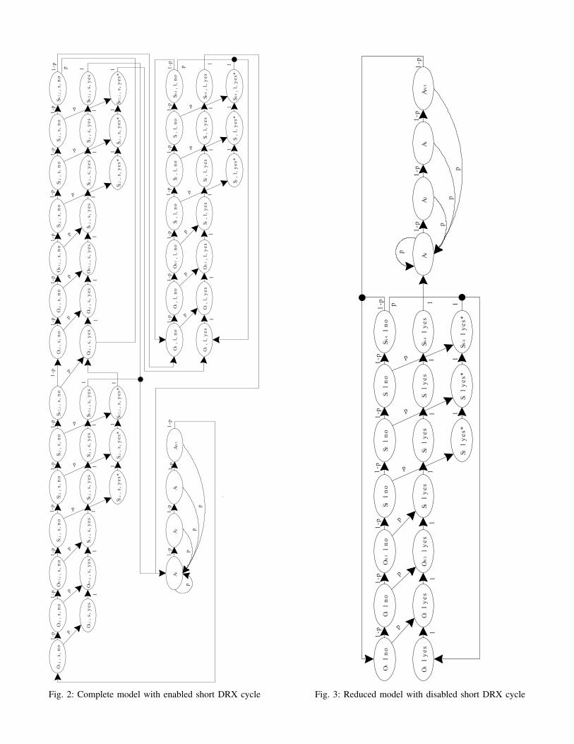
● 1 there is a traffic in the UE buffer.The Markov chain is presented in Fig. 2. The notations in thefigure is different from the description in III-B by using thisrepresentation {Qi,j a, b} and the following abbreviations: ON(O), Sleep (S), Active (A), short (s), long (l).
������
���
�����
���
������
���
������
���
������
���
�����
���
������
���
� �
� �
� �
� �
� �
�����
����
������
����
������
����
������
����
�����
����
������
����
��
��
�
������
����
���
���
����
��
�����
����
��
�
�
�
�
�
�
�
� �
�
����
��
��
�
��
� �
������
���
�����
���
������
���
������
���
������
���
�����
���
������
���
� �
� �
� �
� �
� �
�����
����
������
����
������
����
������
����
�����
����
������
����
��
��
�
������
����
���
���
����
��
�����
����
��
�
�
�
�
�
�
�
� �
����
���
���
���
����
���
����
���
����
���
���
���
����
���
� �
� �
� �
� �
� �
���
����
����
����
����
����
����
����
���
����
����
����
��
��
�
����
����
����
����
��
���
����
��
�
�
�
��
�
�
� �
������
����
�
����
����
�
��
� �
�
� �
�
�
�
� �
�
�� �
�
� �
�
Fig. 2: Complete model with enabled short DRX cycle
����
����
���
�
��
���
���
����
��
��
��
���
���
���
���
���
���
�����
���
����
� �
���
� �
���
� �
���
� �
����
��
��
��
����
�� �
���
�� �
����
���
�
�
�
�
�
�
�
���
�����
��
���
���
�
��� � �
���
�
�
Fig. 3: Reduced model with disabled short DRX cycle

TABLE II: Markov Chain: States
N Notation UE State / Wake up moment i,j ranges [number of SFs]
1 {ON,short,no
i,j} UE in the i-th SF of the j-th short DRX sleep cycle. 1 ≤ i ≤ N1, N1 (onDurationTimer)
There is no traffic in the UE buffer. 1 ≤ j ≤ Ns, Ns (drxShortCycleTimer)1a {
ON,long,noi
} UE in the i-th SF of the long DRX sleep cycle. 1 ≤ i ≤ N3, N3 (onDurationTimer)There is no traffic in the UE buffer.
2 {ON,short,yes
i,j} UE in the i-th SF of the j-th short DRX sleep cycle. 1 ≤ i ≤ N1, N1 (onDurationTimer)
There is traffic in the UE buffer, 2 ≤ j ≤ Ns, Ns (drxShortCycleTimer)wake up after completed DRX cycle
2a {ON,long,yes
i} UE in the i-th SF of the long DRX sleep cycle. 1 ≤ i ≤ N1, N1 (onDurationTimer)
There is traffic in the UE buffer,wake up after completed DRX cycle
3 {Sleep,short,no
i,j} UE in the i-th SF of the j-th short DRX sleep cycle. 1 ≤ i ≤ N2, N2 (shortDRX-Cycle - onDurationTimer)
There is no traffic in the UE buffer. 1 ≤ j ≤ Ns, Ns (drxShortCycleTimer)3a {
Sleep,long,noi
} UE in the i-th SF of the long DRX sleep cycle. 1 ≤ i ≤ N4, N4 (longDRX-Cycle - onDurationTimer)There is no traffic in the UE buffer.
4 {Sleep,short,yes
i,j} UE in the i-th SF of the j-th short DRX sleep cycle. 1 ≤ i ≤ N2, N2 (shortDRX-Cycle - onDurationTimer)
There is traffic in the UE buffer, 1 ≤ j ≤ Ns, Ns (drxShortCycleTimer)wake up after completed DRX cycle
4a {Sleep,long,yes
i} UE in the i-th SF of the long DRX sleep cycle. 1 ≤ i ≤ N4, N4 (longDRX-Cycle - onDurationTimer)
There is traffic in the UE buffer,wake up after completed DRX cycle.
5 {Sleep,short,yes∗
i,j} UE in the i-th SF of the j-th short DRX sleep cycle. 2 ≤ i ≤ N2, N2 (shortDRX-Cycle - onDurationTimer)
Traffic in the UE buffer was generated during sleep. 1 ≤ j ≤ Ns, Ns (drxShortCycleTimer)UE will wake up after next completed DRX cycle
5a {Sleep,long,yes∗
i} UE in the i-th SF of the long DRX sleep cycle. 2 ≤ i ≤ N4, N4 (longDRX-Cycle - onDurationTimer)
Traffic in the UE buffer was generated during sleep.UE will wake up after next completed DRX cycle
6 {Active
i} UE in the i-th SF of the active state. 1 ≤ i ≤ N5, N5 (drx-InactivityTimer)
Zero wake-up delay
D. Markov Chain: Stationary Distribution
Since all states for the Markov chain are aperiodic, recurrentand nonnull, they are all ergodic and the Markov chain is thenergodic. The system then has equilibrium state probabilities.The notation used for the stationary probabilities of the modelstates is Pr {Q, a, b
i, j} where the model notations follow the
same convention as previously.Our strategy is to express all the stationary probabilities
from the state probability of Pr {ON, short, no1, 1
} expressedin (1) with its sub functions (2),(3) and (4). The stationaryprobabilities for: ON duration for short DRX cycle (5), shortDRX sleep cycle (6), ON duration for long DRX cycle(7), long DRX sleep cycle (8) and active state (9) are thenexpressed with (1). Expression (1) as well as the pattern of thestationary state probabilities (5)-(9) has been extracted fromthe normalization equation.
Pr {ON,short, no
1,1} =
1
A +B +C(1)
A = (N1 +N2) ⋅ (1 +1
(1 − p)N1+N2
− 1) ⋅ (2)
⋅ ((1 − p)Ns(N1+N2)
(1 − p)−N2
− (1 − p)N1
)
B = (N3 +N4) ⋅ (1 − p)Ns(N1+N2)
⋅ (3)
⋅
⎛
⎝
(1 − p)N3
1 − (1 − p)N3+N4
+ (1 − p)−N2
⎞
⎠
C =
⎛
⎜
⎝
(1 − (1 − p)Ns(N1+N2)
)
(1 − p)N5
+ (4)
+
(1−p)Ns(N1+N2)
1−(1−p)N3+N4⋅ (1 − (1 − p)
Ns(N3+N4))
(1 − p)N5
⎞
⎟⎟
⎠
⋅1 − (1 − p)
N2
p
Pr {ON in short DRX cycle} = {ON,short, no
1,1} ⋅ (5)
⋅(N1 +N1
(1 − p)N1+N2
− 1⋅ (1 − p)
Ns(N1+N2)
N2 − (1 − p)N1
)
Pr {Sleep in short DRX cycle} = {ON,short, no
1,1} ⋅ (6)
⋅(N2 +N2
(1 − p)N1+N2
− 1⋅ (1 − p)
Ns(N1+N2)
N2 − (1 − p)N1
)
Pr {ON in long DRX cycle} = {ON,short, no
1,1} ⋅ (7)
⋅N3 (1 − p)Ns(N1+N2)
⋅
⎛
⎝
(1 − p)N3
1 − (1 − p)N3+N4
+ (1 − p)−N2
⎞
⎠
Pr {Sleep in long DRX cycle} = {ON,short, no
1,1} ⋅ (8)
⋅N4 ⋅ (1 − p)Ns(N1+N2)
⋅
⎛
⎝
(1 − p)N3
1 − (1 − p)N3+N4
+ (1 − p)−N2
⎞
⎠

Pr {Active} = 1 − (Pr {ON in short DRX cycle}+ (9)+Pr {ON in long DRX cycle}+
+Pr {Sleep in short DRX cycle}+
+Pr {Sleep in long DRX cycle})
E. Performance metrics
The mean wake-up delay is obtained from Little’s law thatexpresses the average time spent waiting in the queue as a ratiobetween the average number of customers in the queue andthe average arrival rate. As explained previously the systemis assumed to have a LIFO queue with size one and only thedelay for the first arrived traffic is obtained. Let X (10) bethe stationary probability that there is traffic in the buffer. Itconsists of two components: Xs for short DRX cycle and Xl
for long DRX cycle each expressing the probability that thereis traffic in the buffer:
X =Xs +Xl (10)
Xs = {ON,short, no
1,1} ⋅ (11)
⋅
⎛
⎝
⎛
⎝
(1 − p)Ns(N1+N2)
− (1 − p)N1+N2
(1 − p)N1+N2
− 1
⎞
⎠
⋅
⋅((N1 +N2) (1 − p)−N2
− 1 +(1 − p)
N1− (1 − p)
p−
−N2 (1 − p)N1
) + (1 − p)N1
⎛
⎝
(1 − p)Ns(N1+N2)
− 1
(1 − p)N1+N2
− 1
⎞
⎠
⋅
⋅
⎛
⎝
N2 +(1 − p)
N2− 1
p
⎞
⎠
+N1 +N2 − 1+
+(1 − p)
N1− (1 − p)
p−N2 (1 − p)
N1⎞
⎠
Xl = {ON,short, no
1,1} ⋅
⎛
⎝
(1 − p)Ns(N1+N2)
1 − (1 − p)N3+N4
⎞
⎠
⋅ (12)
⋅
⎛
⎝
N3 +N4 − 1 − (1 − p)N3
+ (N3 +N4) (1 − p)N3
−
− (N3 +N4) (1 − p)N3+N4
+(1 − p)
N3− (1 − p)
p+
+ (1 − p)N3 (1 − p)
N4− (1 − p)
p
⎞
⎠
+
+{ON,short, no
1,1}
⎛
⎝
(1 − p)(Ns−1)(N1+N2)
((1 − p)N1
−
− (1 − p)N1+N2
(N3 +N4)⎞
⎠
Finally, Little’s law is written as follows. The mean wake-updelay is defined as the probability that there is traffic in the
longDRX-Cycle [ms]500 1000 1500 2000 2500
Mea
n w
ake-
up d
elay
[m
s]
0
500
1000
1500
2000
2500
3000
3500
4000
4500Analytical 1, p=1e-5Analytical 2, p=1e-4Analytical 3, p=1e-3Analytical 4, p=1e-2Analytical 5, p=1e-1Simulation 1, p=1e-5Simulation 2, p=1e-4Simulation 3, p=1e-3Simulation 4, p=1e-2Simulation 5, p=1e-1
Fig. 4: Verification of complete model – Mean wake-up delay
longDRX-Cycle [ms]500 1000 1500 2000 2500
Pow
er s
avin
g fa
ctor
0.4
0.5
0.6
0.7
0.8
0.9
1
Analytical 1, p=1e-5Analytical 2, p=1e-4Analytical 3, p=1e-3Analytical 4, p=1e-2Analytical 5, p=1e-1Simulation 1, p=1e-5Simulation 2, p=1e-4Simulation 3, p=1e-3Simulation 4, p=1e-2Simulation 5, p=1e-1
Fig. 5: Verification of complete model – Power saving factor
buffer divided by the probability that traffic will be generatedinto the buffer:
E [d] =X
p (1 −X)
(13)
The power saving factor η is obtained according to (14) andis defined as the portion of time the UE spends time in sleepstate, both short and long DRX sleep cycle.
η = Pr {Sleep in short DRX cycle}+ (14)+Pr {Sleep in long DRX cycle}
F. Validation
The model is verified by using traffic with different interar-rival times t = {100e3,10e3,1e3,1e2,1e1} in ms converted top = 1
t. The analytical model is verified against the simulator
for this interval of traffic for both mean wake-up delay Fig. 4and power saving factor Fig. 5. The values of the used DRXparameter set are N1 = N3 = 2,N2 = 10, N5 = 10 and Ns = 8.
IV. LTE/LTE-A DRX “REDUCED” MARKOVIAN MODELWITH DISABLED SHORT DRX CYCLE
A. Propositions
The model presented in this section is referred to as areduced one since the short DRX cycle is disabled. Thedisabling of the short DRX cycle and the consideration ofthis model is motivated by propositions below.

Proposition 1: Let the short and long DRX cycles both beenabled and dmax be a deadline for a wake-up delay. Thenthe deadline is always met if 2N4 +N3 < dmax, where N3 isthe ON duration and N4 is the long DRX sleep cycle.
Proof: This proposition directly follows from the operationof the DRX. In the worst delay case traffic is generated withdeadline dmax in the first SF of the long sleep cycle. Theworst case delay is then N4 +N3 +N4 and the deadline willthen always be met if N4 +N3 +N4 < dmax. ∎
Proposition 2: Let the short DRX cycles be disabled anddmax be a deadline for a wake-up delay. Then the deadline isalways met if 2N4+N3 < dmax, where N3 is the ON durationand N4 is the long DRX sleep cycle.
Proof: The proof is analogous to the proof of proposition1. ∎
Therefore, enabling/disabling of the short DRX cycle doesnot influence the conditions for meeting the wake-up deadline.Proposition 3: Let the short DRX cycles be disabled and theinactivity timer N5 be set to its minimum value, then the powersaving factor is maximized.
Proof: Since the same ON state duration is used for bothshort and long DRX cycles, the percentage of time in the sleepstate, is larger for a long DRX cycle compared to a short cyclewhile N4 > N2. It is also necessary to keep the inactivity timervalue as low as possible, to further avoid consuming power bystaying in active state when there is no scheduled traffic. ∎
B. Markov Chain
By disabling the short DRX cycle the reduced model isobtained, Fig. 3. The notation from section III is generic andvalid also here. The states for the reduced model are describedin Table III. The reduced Markov chain is presented in Fig. 3and follows the same logic as the complete one. The approachfor obtaining the stationary probabilities is also the same. Fromthe normalization equation the expression for {
ON, long, no1
}
(15) is obtained and the stationary probabilities for the statesare obtained for ON duration (16), sleep state (17) and activestate (18).
Pr {ON, long,no
1} =
1
A0 +B0 +C0(15)
A0 = N3 +N3 ⋅ ((1 − p)N3
− (1 − p)N3+N4
)
B0 = N4 +N4 ⋅ ((1 − p)N3
− (1 − p)N3+N4
)
C0 =
(1 − (1 − p)N3+N4
) ⋅ (1 − (1 − p)N5
)
p (1 − p)N5
Pr {ON in long DRX cycle} = {ON, long,no
1} ⋅ (16)
⋅ (N3 +N3 ⋅ ((1 − p)N3
− (1 − p)N3+N4
))
Pr {Sleep in long DRX cycle} = {ON, long,no
1} ⋅ (17)
⋅ (N4 +N4 ⋅ ((1 − p)N3
− (1 − p)N3+N4
))
Pr {Active} = 1 − (Pr {ON in long DRX cycle}+ (18)+Pr {Sleep in long DRX cycle})
C. Performance metrics
The same as in complete model, the mean wake-up delay iscomputed by Little’s law. Let X0 be the sum of all probabilitieswhere traffic has arrived i.e. when b ∈ {Y es, Y es∗}:
E [d0] =X0
p (1 −X0)(19)
where
X0 = Pr {ON, long,no
1} ⋅
1
p⋅ (20)
⋅(p2(N1 +N2) (1 − p)
N1+N2−1−
−p (1 − p)N1
(N1 +N2) (1 − p)N2−1
+
+ ((1 − p)N2
+ (N1 +N2)p) (1 − p)N1
− 1 + (N1 +N2)p).
The power saving factor is defined as the portion of timethe UE spends in sleep and it is simply:
η0 = Pr {Sleep in long DRX cycle} (21)
D. Validation
The reduced model is verified, in the same way as thecomplete model, for both mean wake-up delay Fig. 6 andpower saving factor Fig. 7. The values of the used DRXparameter set are N3 = 2 and N5 = 10.
V. PERFORMANCE EVALUATION
A. Preliminaries
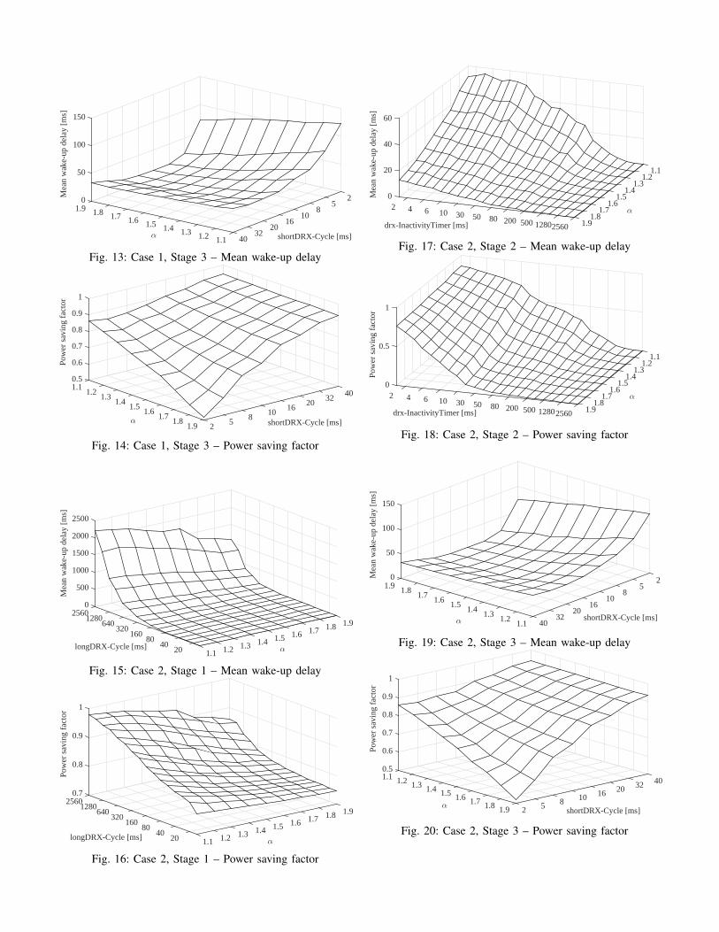
The results for the DRX mechanism evaluation are dividedinto two subsections presenting firstly military training trafficresults and secondly multimedia traffic results. In subsectionV-B propositions 2 and 3 have been used for meeting the wake-up deadlines while maximizing power saving factor by usingthe reduced DRX mechanism. Results are presented using asimple traffic model representing military training application.In subsection V-C results are presented for the complete DRXmechanism using a simulator enabled to queue all trafficduring DRX cycle together with a multimedia traffic modelwith simplified bounded-Pareto distribution. Since the trafficarrival model used here does not have memoryless properties,the simulators are used for this evaluation instead.
The valid DRX parameter values from the 3GPP standard[16]-[17] are used. A short and fixed ON duration parameteris assumed and it is not further investigated due to it being

TABLE III: Markov Chain: States for model with disabled short DRX cycle
N Notation UE State / Wake up moment i ranges [number of SFs]
1 {ON,long,no
i} UE in the i-th SF of the long DRX sleep cycle. 1 ≤ i ≤ N3, N3 (onDurationTimer)
There is no traffic in the UE buffer.2 {
ON,long,yesi
} UE in the i-th SF of the long DRX sleep cycle. 1 ≤ i ≤ N3, N3 (onDurationTimer)There is traffic in the UE buffer,
wake up after completed DRX cycle
3 {Sleep,long,no
i} UE in the i-th SF of the long DRX sleep cycle. 1 ≤ i ≤ N4, N4 (longDRX-Cycle - onDurationTimer)
There is no traffic in the UE buffer.4 {
Sleep,long,yesi
} UE in the i-th SF of the long DRX sleep cycle. 1 ≤ i ≤ N4, N4 (longDRX-Cycle - onDurationTimer)There is traffic in the UE buffer,
wake up after completed DRX cycle.5 {
Sleep,long,yes∗i
} UE in the i-th SF of the long DRX sleep cycle. 2 ≤ i ≤ N4, N4 (longDRX-Cycle - onDurationTimer)Traffic in the UE buffer was generated during sleep.UE will wake up after next completed DRX cycle
6 {Active
i} UE in the i-th SF of the active state. 1 ≤ i ≤ N5, N5 (drx-InactivityTimer)
Zero wake-up delay
longDRX-Cycle [ms]500 1000 1500 2000 2500
Mea
n w
ake-
up d
elay
[m
s]
0
500
1000
1500
2000
2500
3000
3500
4000
4500Analytical 1, p=1e-5Analytical 2, p=1e-4Analytical 3, p=1e-3Analytical 4, p=1e-2Analytical 5, p=1e-1Simulation 1, p=1e-5Simulation 2, p=1e-4Simulation 3, p=1e-3Simulation 4, p=1e-2Simulation 5, p=1e-1
Fig. 6: Verification of reduced model – Mean wake-up delay
longDRX-Cycle [ms]500 1000 1500 2000 2500
Pow
er s
avin
g fa
ctor
0.4
0.5
0.6
0.7
0.8
0.9
1
Analytical 1, p=1e-5Analytical 2, p=1e-4Analytical 3, p=1e-3Analytical 4, p=1e-2Analytical 5, p=1e-1Simulation 1, p=1e-5Simulation 2, p=1e-4Simulation 3, p=1e-3Simulation 4, p=1e-2Simulation 5, p=1e-1
Fig. 7: Verification of reduced model – Power saving factor
a parameter primarily used for providing the scheduler flex-ibility, even if it certainly influences both power saving anddelay. The valid range and the values for the DRX parametersare according to Table IV.
B. Military training traffic results
In this case the impact of the DRX mechanism on thedelay and the power saving factor is investigated for a militarytraining application. Military training traffic can be comparedto IoT traffic with long latencies and large mean interarrivaltimes, in the order of seconds. The mobile nodes (UEs) in
TABLE IV: DRX Parameters
Name Notation Range [SFs]onDurationTimer N1 = N3 1, 2, 3, 4, 5
6, 8, 10, 20, 30, 4050, 60, 80, 100, 200
shortDRX-Cycle N1 +N2 2, 5, 8, 10, 16, 2032, 40, 64, 80, 128, 160
256, 320, 525, 640longDRX-Cycle N3 +N4 10, 20, 32, 40, 64, 80
128, 160, 256, 320, 512640, 1024, 1280, 2048
2560drx-InactivityTimer N5 1, 2, 3, 4, 5, 6, 8, 10, 20
30, 40, 50, 60, 80, 100200, 300, 500, 7501280, 1920, 2560
drxShortCycleTimer Ns 1,...,16
a military training network consist of mostly two kinds ofplayer types; soldiers and vehicles. Their traffic pattern andrequirements specifically within a LTE network has been char-acterized for a realistic military training application scenarioand resulted in the traffic model in Table V. For each playertype there may be several types of traffic for each direction,uplink or downlink. Each traffic type is expressed with auniformly distributed mean interarrival time that representsthe average behavior of a specific traffic type and a maximumlatency. For each player type all traffic in each direction ismerged into a new mean interarrival time t which is usedtogether with the lowest latency requirement.
This results in the 4 stages of traffic as in Table V withthe combination of uplink or downlink traffic for soldiers andvehicles. It should be noted as already has been described thatthe division of uplink and downlink traffic is for presentationof military traffic purpose since it is assumed that boththe uplink and downlink traffic are detected with the sameprocedure, i.e. during the ON duration only. Meaning thatwake-up delay is calculated in the same way for both trafficdirections.
Mean interarrival time t, is expressed in number of SFs orms, then p = 1
t.

TABLE V: Military application traffic model
Soldier VehicleUplink Latency= 3s Latency=0.5s
t = 10e3+100e32
= 55e3 t = 5e3+30e32
= 17.5e3
p = 155e3
p = 117.5e3
Downlink Latency=1-3s Latency=1-3st = 250+30e3
2= 15.125e3 t = 250+60e3
2= 30.125e3
p = 15.125e3
p = 130.125e3
longDRX-Cycle [ms]500 1000 1500 2000 2500
Mea
n w
ake-
up d
elay
[m
s]
0
500
1000
1500
2000
2500
3000
3500
4000Analytical 1, p=1/55e3Analytical 2, p=1/17.5e3Analytical 3, p=1/5.125e3Analytical 4, p=1/30.125e3Simulation 1, p=1/55e3Simulation 2, p=1/17.5e3Simulation 3, p=1/5.125e3Simulation 4, p=1/30.125e3
Fig. 8: Military traffic model – Mean wake-up delay
longDRX-Cycle [ms]500 1000 1500 2000 2500
Pow
er s
avin
g fa
ctor
0.8
0.85
0.9
0.95
1
Analytical 1, p=1/55e3Analytical 2, p=1/17.5e3Analytical 3, p=1/5.125e3Analytical 4, p=1/30.125e3Simulation 1, p=1/55e3Simulation 2, p=1/17.5e3Simulation 3, p=1/5.125e3Simulation 4, p=1/30.125e3
Fig. 9: Military traffic model – Power saving factor
The results for the military traffic model can be seen inFig. 8 and 9 for mean wake-up delay and power saving factorrespectively. Since the results are almost indistinguishable forthe player types and the traffic directions, it is assumed thecurrent difference in mean interarrival times do not affect thewake-up delay of the power saving factor in a noticeable way.The four different cases then just need to meet their respectivewake-up deadlines for fulfilling the traffic latency requirementsaccording to proposition 2. This gives that the longDRX-Cycleshall be N4 <
(dmax−N3)2
and selected from the valid range ofvalues from Table IV. The N3 = 2ms, parameter is fixed andthe N5 = 1 parameter is selected based on proposition 3 tomaximize the power saving factor.
Vehicle player type with uplink traffic needs to meet a wake-up deadline dmax = 500 ms so the longDRX-Cycle shall beN4 <
(dmax−N3)2
= 249 ms, this gives a valid value of 160 ms.The maximum power saving factor will then be 0.9875 forthis player type using current parameter values.
Both vehicle and soldier with downlink traffic need to meeta deadline of dmax = 1 s so the longDRX-Cycle shall be N4 <
(dmax−N3)2
= 499 ms, this gives a valid value of 320 ms. Themaximum power saving factor will then be 0.9937 for theseplayer types using current parameter values.
Soldier with uplink traffic needs to meet a deadline of 3slongDRX-Cycle shall be N4 <
(dmax−N3)2
= 1499 ms, this givesa valid value of 1280 ms. The maximum power saving factorwill then be 0.9984 for this player type using current parametervalues.
C. Multimedia results
In this subsection the complete DRX mechanism as de-scribed in section III is used together with a traffic modelgenerating interarrival times modeling multimedia traffic forevaluation of the DRX mechanism behavior.
1) Traffic model: In [3] it is described that multimediatraffic exhibits self-similarity properties and that the Paretodistribution fits well into the packet interarrival time of self-similar traffic. In the 3GPP traffic model [18] the bounded-Pareto distribution is used and it provides a lower L andalso an upper H limit for the distribution, that in our modelrepresents the traffic interarrival times. Additionally to avoidcomplicated mathemathical derivations, a simplified bounded-Pareto distribution is used in the 3GPP traffic model and alsoin [3] that we adopt. By using inverse transform samplingthe formula for generating truncated Pareto distribution is ob-tained. Given a random number U with a uniform distributionon the interval ((
LH)α,1] the formula for generating random
numbers of simplified bounded-Pareto distribution is:
x =L
U1/α (22)
where 1.1 ≤ α ≤ 1.9 for self-similair traffic.Two cases are investigated in detail for evaluating the effect
of the DRX mechanism on the wake-up delay and the powersaving factor when self-similar traffic is used. In case one onlythe delay caused by the DRX cycle is investigated withoutconsidering the active state. In case two the active part is alsoconsidered and hence the impact of the inactivity timer/activestate on the delay. For both cases it is assumed that traffic canarrive and will be registered at any SF during the DRX cycle,unlike the models in section III and IV that only registers thefirst arrived traffic during the DRX cycle. This means that aqueue is used that during DRX cycle registers all the generatedtraffic and is emptied upon entering active state whereby the(DRX created) wake-up delay is obtained for all the trafficthat was generated since previous active state.
2) Case 1 - Do not consider active state: In this case it isassumed that traffic can arrive and will be registered in anySF in the UE or in the base station during DRX. Howeveronly the delay incurred by the DRX cycle is considered forthe mean wake-up delay and not the contribution of the activestate, i.e. traffic generated during active state with zero wakeup delay do not contribute to the mean wake-up delay for theUE.
If multimedia traffic according to the traffic model aboveis generated in a UE, it can be assumed that there will notbe a big difference of the pattern of the traffic if the military

traffic model in Table V is added onto the multimedia traffic.Assuming that the multimedia traffic is a uplink stream forsupervision purpose, we then use a deadline of 500 ms forthis traffic. The shortest wake-up deadline that needs to be metis then dmax = 500ms and proposition 1 gives us that N4 <
(dmax−N3)2
= 249 when N3 = 2ms. From the range of DRXparameter values in Table IV it is obtained that N4 = 160msis the largest long DRX cycle value fulfilling this requirement.
The onDurationTimer and the drxShortCycleTimer parame-ters will affect the results but they are not crucial for designingthe DRX functionality which leaves us with 3 parameters toevaluate. The evaluation is performed in three stages with oneDRX parameter at each stage. The most important parameteris selected first which is the long sleep cycle since it iscritical to meet a wake-up delay. Out of the remaining twoparameters the drxInactivityTimer is selected as second sinceit can affect the result drastically, for example for certain typeof traffic if the drxInactivityTimer is large enough then theUE can spend a large portion of the time in active modeand drastically decrease both delay and possible power savingfactor. The shortDRX-Cycle is selected as the third parametersince it is not critical for meeting the traffic deadline as long asN3 ≤ N4 as is indirectly given since largeDRX-Cycle shall bea multiple of shortDRX-Cycle according to the standard [16]-[17], also selecting drxShortCycleTimer within any of its validrange is not immediately foreseen to cause a drastic changein terms of the impact of the shortDRX-Cycle parameter. Foreach stage both the evaluations are done based on the definedperformance metrics.
If nothing else is stated then the following parameter valuesare used; N1 = N3 = 2ms, N2 = 10ms, N4 = 160ms, N5 =
1ms and Ns = 8. The Pareto parameter α is evaluated in therange of self-similair traffic in every stage.
Stage 1: It is clear from Fig. 10 and 11 that increasinglongDRX-Cycle increases the power saving factor with in-creased mean wake-up delay as a result. The pattern is similairfor all α values.
Stage 2: It can not be determined that the drxInactivityTimercan affect the mean-wake up delay if its contribution is notconsidered in the delay, so mean wake-up delay is not analyzedfurther here. Evaluating the drxInactivityTimer (Fig. 12) itis clear that when this timer value is increased the UE isspending more time in active state than in DRX cycle andthe power saving factor is decreased to zero for higher valuesof drxInactivityTimer in precence of the traffic.
Stage 3: Having evaluated the drastic effect of drxInac-tivityTimer on the power saving factor without consideringits effect on the mean wake-up delay, we show that undercurrent parameter set, the maximum difference in power savingfactor is not more than ≈ 9 − 33% within the valid ranges ofshortDRX-Cycle values (Fig. 14). The mean wake-up delay isat the lowest in the middle of the valid range of shortDRX-Cycle values (Fig. 13). It can be seen that very short valuescreates the longest mean wake-up delays values since it putsthe UE into long sleep faster.
3) Case 2 - Consider active state: Similar to case 1 thereis no queuing restriction during DRX however the active statecontribution to mean wake-up delay is considered here, i.e.
1.91.81.71.6
α
1.51.41.31.21.120 40
80 longDRX-Cycle [ms]
160 320
640 1280
1500
1000
500
0
2000
2500
2560
Mea
n w
ake-
up d
elay
[m
s]
Fig. 10: Case 1, Stage 1 – Mean wake-up delay
1.91.81.71.61.5
α 1.41.31.21.120
40 80
longDRX-cycle [ms]
160 320
640 1280
0.7
0.8
0.9
1
2560Po
wer
sav
ing
fact
or
Fig. 11: Case 1, Stage 1 – Power saving factor
1.11.2
1.3
α
1.41.5
1.61.7
1.81.925601280500 200 80 50
drx-InactivityTimer [ms]
30 10 6 4 2 0
1
0.5
Pow
er s
avin
g fa
ctor
Fig. 12: Case 1, Stage 2 – Power saving factor
traffic generated during active state have zero wake-up delayand will contribute to the mean wake-up delay.
Stage 1: The impact of the longDRX-Cycle on the per-formance metrics when considering the active state (Fig. 15-16) are not distinguishable compared to when active state isnot considered (Fig. 10-11). The trend is the same, longerlongDRX-Cycle increases delay and power saving factor.
Stage 2: The expected result of the increase of the drxInac-tivityTimer upon the mean wake-up delay is verified by Fig. 17where the mean wake-up delay is zero after sufficiently longtimer value. Comparing the impact of drxInactivityTimer onthe power saving delay, no clear difference is distinguishablebetween case 1 (Fig. 12) and case 2 (Fig. 18).
Stage 3: The difference between the impact of shortDRX-
2
shortDRX-Cycle [ms]
5 8
1016
2032
401.11.21.31.4α
1.51.61.71.81.90
100
50
150
Mea
n w
ake-
up d
elay
[m
s]
Fig. 13: Case 1, Stage 3 – Mean wake-up delay
40
shortDRX-Cycle [ms]
3220
1610
8 5
2 1.91.8
1.71.6
1.5
α
1.41.3
1.2
1
0.8
0.7
0.5
0.9
0.6
1.1
Pow
er s
avin
g fa
ctor
Fig. 14: Case 1, Stage 3 – Power saving factor
1.91.81.71.6
α 1.51.41.31.21.120
40 80
longDRX-Cycle [ms]
160 320
640 1280
2500
0
500
1500
1000
2000
2560
Mea
n w
ake-
up d
elay
[m
s]
Fig. 15: Case 2, Stage 1 – Mean wake-up delay
1.91.81.71.61.5
α 1.41.31.21.120
40 80
longDRX-Cycle [ms]
160 320
640 1280
0.7
0.8
1
0.9
2560
Pow
er s
avin
g fa
ctor
Fig. 16: Case 2, Stage 1 – Power saving factor
1.11.2
1.31.4
α
1.51.6
1.71.8
1.925601280500 200 80 50 30 drx-InactivityTimer [ms]
10 6 4 2
20
0
60
40
Mea
n w
ake-
up d
elay
[m
s]
Fig. 17: Case 2, Stage 2 – Mean wake-up delay
1.11.2
1.3
α
1.41.5
1.61.7
1.81.925601280500 200 80 50
drx-InactivityTimer [ms]30 10 6 4 2
1
0
0.5
Pow
er s
avin
g fa
ctor
Fig. 18: Case 2, Stage 2 – Power saving factor
2
shortDRX-Cycle [ms]
5 8
1016
2032
401.11.2
1.31.4
α
1.51.6
1.71.8
1.9
150
100
0
50
Mea
n w
ake-
up d
elay
[m
s]
Fig. 19: Case 2, Stage 3 – Mean wake-up delay
4032
shortDRX-Cycle [ms]
2016108 5 2 1.91.81.71.61.5
α
1.41.31.2
0.5
0.6
0.7
0.8
0.9
1
1.1
Pow
er s
avin
g fa
ctor
Fig. 20: Case 2, Stage 3 – Power saving factor

Cycle upon the performance metrics when active state isconsidered (Fig. 19-20) or not (Fig. 13-14), can not bedistinguished.
VI. CONCLUSIONS
We have presented probabilistic models to evaluate theDiscontinuous Reception Mechanism (DRX) of LTE/LTE-Anetworks. With a special emphasis on the military training ap-plication types of traffic, we have quantitatively characterizedthe performance of the network in terms of mean wake-updelay and power saving factor.
Our future work will be dedicated to the energy-efficiencymanagement methods, when they are implemented at the basestation side.
REFERENCES
[1] S. R. Yang, S. Y. Yan, and H. N. Hung, “Modeling UMTS Power Savingwith Bursty Packet Data Traffic,” IEEE Trans. on Mobile Comput., vol.6, no. 12, pp. 1398-1409, Dec. 2007.
[2] A. Koc, S. C. Jha, R. Vannithamby, and M. Torlak, “Device powersaving and latency optimization in LTE-A networks through DRXconfiguration,” IEEE Trans. Wireless Commun., vol. 13, no. 5, pp. 2614-2625, May 2014.
[3] K. Wang, X. Li, H. Ji, and X. Du, “Modeling and optimizing theLTE discontinuous reception mechanism under self-similar traffic,” IEEETrans. Veh. Technol., to be published.
[4] K. Zhou, N. Nikaein, and T. Spyropoulos, “LTE/LTE-A discontinuousreception modeling for machine type communications,” IEEE WirelessCommun. Lett., vol. 2, no. 1, pp. 102-105, Feb. 2013.
[5] S. Baek and B. D. Choi, “Analysis of discontinuous reception (DRX)with both downlink and uplink packet arrivals in 3GPP LTE,” in Proc.6th Int. Conf. Queueing Theory and Network Appl., New York, 2011,pp. 8-16.
[6] H. C. Wang, C. C. Tseng, G. Y. Chen, F. C. Kuo, and K. C. Ting,“Power saving by LTE DRX mechanism using a mixture of short andlong cycles,” in Proc. IEEE Region 10 Conference (31194) TENCON2013, Xi’an, 2013, pp. 1-6.
[7] Y. Y. Mihov, K.M. Kassev, and B.P. Tsankov, “Analysis and performanceevaluation of the DRX mechanism for power saving in LTE,” in Proc.IEEE 26th Conv. Elect. and Electron. Eng. Israel, 2010, pp. 520-524.
[8] S. Fowler, R. S. Bhamber, and A. Mellouk, “Analysis of adjustableand fixed DRX mechanism for power saving in LTE/LTE-Advanced,”in Proc. IEEE Int. Conf. Commun., 2012, pp. 1964-1969.
[9] Z. Zhang, Z. Zhao, H. Guan, L. Du, and Z. Tan, “Performance analysisof an adaptive DRX mechanism with flexible short/long cycle switchingin LTE network,” in Proc. IEEE 5th Int. Symp. Microwave, Antenna,Propagation EMC Technologies Wireless Commun., 2013, pp. 27-32.
[10] C. S. Bontu and E. Illidge, “DRX mechanism for power saving in LTE,”IEEE Commun. Mag., vol. 47, no. 6, pp. 48-55, June 2009.
[11] J. M. Liang, J. J. Chen, H. H. Cheng, and Yu-Chee Tseng, “Anenergy-efficient sleep scheduling with QoS consideration in 3GPP LTE-advanced networks for internet of things,” IEEE J. Emerg. Sel. TopicsCircuits and Syst., vol. 3, no. 1, pp. 13-22, Mar. 2013.
[12] A. Elnashar and M. A. El-Saidny, “Extending the Battery Life ofSmartphones and Tablets: A Practical Approach to Optimizing the LTENetwork,” IEEE Veh. Technol. Mag., vol. 9, no. 2, pp. 38-49, June 2014.
[13] C. Zarakovitis and Q. Ni, “Energy efficient designs for communicationsystems: resolutions on inverse resource allocation principles,” IEEECommun. Lett., vol. 17, no. 12, pp. 2264-2267, Dec. 2013.
[14] Q. Ni and C. Zarakovitis, “Nash bargaining game theoretic schedulingfor joint channel and power allocation in cognitive radio systems,” IEEEJ. Sel. Areas Commun., vol. 30, no. 1, pp. 70-81, Jan. 2012.
[15] C. Zarakovitis, Q. Ni, D.E. Skordoulis, and M.G. Hadjinicolaou, “Power-efficient cross-layer design for OFDMA systems with heterogeneousQoS, imperfect CSI, and outage considerations,” IEEE Trans. Veh.Technol., vol. 61, no. 2, pp. 781-798, Feb. 2012.
[16] Technical specification group radio access network; evolved universalterrestrial radio access (E-UTRA); radio resource control (RRC); pro-tocol specification, 3GPP TS 36.331 V8.9.0, 2010.
[17] Technical specification group radio access network; evolved universalterrestrial radio access (E-UTRA); medium access control (MAC) pro-tocol specification, 3GPP TS 36.321 V8.8.0, 2012.
[18] Feasibility study for ofdm for utran enhancement, 3GPP TR 25.892,Tech. Rep. 2.0.0 (Release 6), 2004.
Hawar Ramazanali received the Master’s degree inelectronics design from Linkoping University, Cam-pus Norrkoping, Norrkoping, Sweden in 2006. Heis currently an industrial PhD student at HalmstadUniversity and has been working with radio systemsat Saab Training and Simulation since 2008.
Alexey Vinel (M’07–SM’12) received the Bache-lor’s (Hons.) and Master’s (Hons.) degrees in infor-mation systems from Saint-Petersburg State Univer-sity of Aerospace Instrumentation, Saint Petersburg,Russia, in 2003 and 2005, respectively; the Ph.D.degree in technology from the Institute for Infor-mation Transmission Problems, Moscow, Russia, in2007; and Ph.D. degree in technology from Tam-pere University of Technology, Tampere, Finland, in2013.
He is currently a Professor of data communi-cations with the School of Information Technology, Halmstad University,Halmstad, Sweden. He has been involved in research projects on vehicularnetworking standards, advanced driver-assistance systems, and autonomousdriving.
Dr. Vinel has been an Associate Editor for the IEEE COMMUNICATIONSLETTERS since 2012 and IEEE WIRELESS COMMUNICATIONS MAGA-ZINE since 2015.