Embed Size (px)
Citation preview

U.S. Department of Housing and Urban Development Office of Policy Development and Research
PRESCRIPTIVE METHOD FOR INSULATING CONCRETE FORMS IN RESIDENTIAL
CONSTRUCTION Second Edition
ICCF BLOCK SYSTEMS 8960 W. Larkspur Drive Ste. 105
Peoria, Arizona 85381
www.theperfectblock.com888-623-4223

PATH (Partnership for Advancing Technology in Housing) is a new private/public effort to develop, demonstrate, and gain widespread market acceptance for the “Next Generation” of American housing. Through the use of new or innovative technologies, the goal of PATH is to improve the quality, durability, environmental efficiency, and affordability of
tomorrow’s homes.
PATH is managed and supported by the U.S. Department of Housing and Urban Development (HUD). In addition, all
federal agencies that engage in housing research and technology development are PATH Partners, including the
Departments of Energy, Commerce, and Agriculture as well as the Environmental Protection Agency (EPA) and the
Federal Emergency Management Agency (FEMA). State and local governments and other participants from the public
sector are also partners in PATH. Product manufacturers, home builders, insurance companies, and lenders represent
private industry in the PATH Partnership.
To learn more about PATH, please contact
451 7th Street, SW
Suite B 133 Washington, DC 20410
202-708-5873 (fax) 202-708-4277 (phone)
e-mail: [email protected] website: www.pathnet.org
Visit PD&R's website
www.huduser.org to find this report and others sponsored by
HUD's Office of Policy Development and Research (PD&R).
Other services of HUD USER, PD&R's Research Information Service, include list servs; special interest, bimonthly
publications (best practices, significant studies from other sources); access to public use databases; and a hotline 1-
800-245-2691 for help accessing the information you need.

PRESCRIPTIVE METHOD FOR INSULATING CONCRETE FORMS IN
RESIDENTIAL CONSTRUCTION Second Edition
Prepared for
U.S. Department of Housing and Urban Development
Office of Policy Development and Research Washington, DC
and
Portland Cement Association
Skokie, IL
and
National Association of Home Builders Washington, DC
by
NAHB Research Center, Inc. Upper Marlboro, MD
Contract H-21172CA
January 2002

DISCLAIMER
Neither the U.S. Department of Housing and Urban Development of the U.S. Government, nor the
Portland Cement Association, nor the National Association of Home Builders, nor the NAHB
Research Center, Inc., nor its employees or representatives makes any warranty, guarantee, or
representation, expressed or implied, with respect to the accuracy or completeness of information
contained in this document or its fitness for any particular purpose, or assumes any liability for
damages or injury resulting from the applications of such information. Users are directed to perform all
work in accordance with applicable building code requirements.
NOTICE
The contents of this report are the views of the contractor and do not necessarily reflect the views or
policies of the U.S. Department of Housing and Urban Development or the U.S. government. The
U.S. government does not endorse products or manufacturers. Trade or manufacturer names appear
herein solely because they are considered essential to the object of this report.

PRESCRIPTIVE METHOD FOR INSULATING CONCRETE FORMS
IN RESIDENTIAL CONSTRUCTION, Second Edition
Foreword In the past several years the U.S. Department of Housing and Urban Development (HUD) has
focused on a variety of innovative building materials and systems for use in residential construction.
HUD’s efforts have addressed barriers to innovations and promoted education of home builders, home
buyers, code officials, and design professionals. Key issues include building material or system
limitations, advantages, availability, technical guidelines, and installed cost. Efforts on these issues have
fostered the development, acceptance, and implementation of innovative construction technologies by
the home building industry. Innovative design and construction approaches using wood, steel, and
concrete materials have thus far been addressed as viable alternatives to conventional residential
construction methods and materials.
Insulating Concrete Forms (ICFs) represent a category of building product that is receiving greater
attention among builders. ICFs are hollow blocks, planks, or panels that can be constructed of rigid
foam plastic insulation, a composite of cement and foam insulation, a composite of cement and
wood chips, or other suitable insulation material that has the ability to act as forms for cast-in-place
concrete walls. The forms typically remain in place after the concrete has cured, providing well-
insulated construction. ICFs continue to gain popularity because they are competitive with light-
frame construction and offer a strong, durable, and energy-efficient wall system for housing.
The first edition of the Prescriptive Method for Insulating Concrete Forms in Residential
Construction represented the outcome of an initial effort to fulfill the need for prescriptive
construction requirements and to improve the overall affordability of homes constructed with
insulating concrete forms. The first edition also served as the source document for building code
provisions in the International Residential Code (IRC).
The second edition expands on the first edition by adding provisions for Seismic Design Categories
C and D (Seismic Zones 3 and 4). Wall construction requirements utilizing Grade 60 reinforcing
steel and concrete mixes with selected compressive strengths are included. In addition, tables
throughout the document have been simplified as a result of additional evaluation and user input.
We believe that providing this type of information to the home building industry promotes healthy
competition, helps to define optimal use of our nation’s natural resources, and enhances housing
affordability.
Lawrence L. Thompson
General Deputy Assistant Secretary for Policy Development and Research
PRESCRIPTIVE METHOD FOR INSULATING CONCRETE FORMS
IN RESIDENTIAL CONSTRUCTION, Second Edition
Acknowledgments
This report was prepared by the NAHB Research Center, Inc., under sponsorship of the U.S.
Department of Housing and Urban Development (HUD). We wish to recognize the Portland
Cement Association (PCA) and the National Association of Home Builders (NAHB) whose co
funding and participation made the project possible. Special appreciation is extended to William
Freeborne of HUD and David Shepherd of PCA, for guidance throughout the project. Joseph J.
Messersmith and Stephen V. Skalko of PCA are also recognized for their technical review and
insights.
The principal authors of this document are Shawn McKee (Second Edition) and Andrea Vrankar, P.E.,
R.A. (First Edition) with technical review and assistance provided by Jay Crandell, P.E.
Administrative support was provided by Lynda Marchman. Special appreciation is also extended to
Nader Elhajj, P.E., a co-author of the first edition of the Prescriptive Method for Insulating
Concrete Forms in Residential Construction. Appreciation is especially extended to members of the
review committee (listed below) who provided guidance on the second edition of the document and
whose input contributed to this work. Steering committee members who participated in the
development of the first edition are also recognized below.
Second Edition Review Committee Ron Ardres, Reddi-Form, Inc.
Karen Bexton, P.E., Tadrus Associates, Inc.
Pat Boeshart, Lite-Form, Inc.
Kelly Cobeen, S.E., GFDS Engineers
Jay Crandell, P.E., NAHB Research Center, Inc.
Dan Dolan, PhD., Virginia Polytechnic and State
University
Kelvin Doerr, P.E., Reward Wall Systems, Inc.
William Freeborne, P.E., U.S. Department of
Housing and Urban Development
S.K. Ghosh, PhD., SK Ghosh and Associates
Shawn McKee, NAHB Research Center, Inc. Jim
Messersmith, Portland Cement Association Rich
Murphy, American Polysteel Forms
David Shepherd, Portland Cement Association
Robert Sculthorpe, ARXX Building Products,
Inc.
Steven Skalko, Portland Cement Association
Andrea Vrankar, P.E., R.A, U.S. Department of
Housing and Urban Development
Robert Wright, P.E., R.W. Wright Design
The NAHB Research Center, Inc., appreciates and recognizes the following companies that
provided ICFs, tools, and other materials to support various research and testing efforts.
AAB Building System, Inc. Reddi-Form, Inc.
American Polysteel Forms Reward Wall Systems
Avalon Concepts Corp. Topcraft Homes, Inc.
Lite-Form, Inc.
First Edition Steering Committee
Ron Ardres, Reddi-Form, Inc. Pat Boeshart, Lite-Form, Inc.
Barney Barnett, Superior Built Jonathan Childres, North State Polysteel
Lance Berrenberg, American Polysteel Jay Crandell, P.E., NAHB Research Center,
Forms Inc.

PRESCRIPTIVE METHOD FOR INSULATING CONCRETE FORMS IN
RESIDENTIAL CONSTRUCTION, Second Edition
Bill Crenshaw, Perma-Form Components, Inc.
Ken Demblewski, Sr., P.E., K and B Associates,
Inc.
Nader Elhajj, P.E., NAHB Research Center, Inc.
Anne Ellis, P.E., National Ready-Mix Concrete
Association
William Freeborne, P.E., U.S. Department of Housing and Urban Development
Thomas Greeley, BASF Corporation
David Hammerman, P.E., Howard County
(Maryland) Department of Inspections,
Licenses, and Permits
Bob Hartling, Poly-Forms, LLC
Gary Holland, Perma-Form Components, Inc.
Byron Hulls, Owens-Corning
Raj Jalla, Consulting Engineers Corp.
Lionel Lemay, P.E., Portland Cement
Association
Paul Lynch, Fairfax County (Virginia)
Department of Inspection Services
Roger McKnight, Romak & Associates, Inc.
Andrew Perlman, Alexis Homes
T. Reid Pocock, Jr., Dominion Building Group,
Inc.
Frank Ruff, TopCraft Homes, Inc.
Robert Sculthorpe, AAB Building System, Inc.
Dean Seibert, Avalon Concepts Corp.
Jim Shannon, Huntsman Chemical Corp.
Steven Skalko, P.E., Portland Cement
Association
Herbert Slone, Owens-Corning
Glen Stoltzfus, VA Polysteel Wall Systems Donn
Thompson, Portland Cement Association Stan
Traczuk, Avalon Concepts Corp.
Ned Trautman, Owens-Corning
Andrea Vrankar, P.E.,R.A., NAHB Research
Center, Inc.
Hansruedi Walter, K-X Industries, Inc.
Dick Whitaker, Insulating Concrete Form
Association
Lee Yost, Advanced Building Structure
Roy Yost, Advanced Building Structure

PRESCRIPTIVE METHOD FOR INSULATING CONCRETE FORMS
IN RESIDENTIAL CONSTRUCTION, Second Edition
Table of Contents
Page
Foreword .......................................................................................................................................iii
Acknowledgments ........................................................................................................................... v
Executive Summary ...................................................................................................................... xvi
PART I - PRESCRIPTIVE METHOD
Introduction ...................................................................................................................................I-1
1.0 General ..............................................................................................................................I-2
1.1 Purpose .................................................................................................................. I-2
1.2 Approach ............................................................................................................... I-2
1.3 Scope .....................................................................................................................I-2
1.4 ICF System Limitations .........................................................................................I-3
1.5 Definitions .............................................................................................................I-5
2.0 Materials, Shapes, and Standard Sizes .............................................................................I-11
2.1 Physical Dimensions ............................................................................................I-11
2.2 Concrete Materials ............................................................................................... I-11
2.3 Form Materials .................................................................................................... I-12
3.0 Foundations .....................................................................................................................I-15
3.1 Footings ............................................................................................................... I-16
3.2 ICF Foundation Wall Requirements .....................................................................I-16
3.3 ICF Foundation Wall Coverings .......................................................................... I-17
3.4 Termite Protection Requirements ......................................................................... I-18
4.0 ICF Above-Grade Walls ..................................................................................................I-30
4.1 ICF Above-Grade Wall Requirements .................................................................I-30
4.2 ICF Above-Grade Wall Coverings .......................................................................I-30
5.0 ICF Wall Opening Requirements .....................................................................................I-38
5.1 Minimum Length of ICF Wall without Openings ................................................I-38
5.2 Reinforcement around Openings .......................................................................... I-38
5.3 Lintels ..................................................................................................................I-37
6.0 ICF Connection Requirements .........................................................................................I-64
6.1 ICF Foundation Wall-to-Footing Connection ....................................................... I-64
6.2 ICF Wall-to-Floor Connection .............................................................................I-64
6.3 ICF Wall-to-Roof Connection ..............................................................................I-66

PRESCRIPTIVE METHOD FOR INSULATING CONCRETE FORMS IN
RESIDENTIAL CONSTRUCTION, Second Edition
7.0 Utilities ............................................................................................................................I-73
7.1 Plumbing Systems ...............................................................................................I-73
7.2 HVAC Systems ...................................................................................................I-73
7.3 Electrical Systems ............................................................................................... I-73
8.0 Construction and Thermal Guidelines ............................................................................. I-74
8.1 Construction Guidelines ......................................................................................I-74
8.2 Thermal Guidelines ............................................................................................. I-74
9.0 References .......................................................................................................................I-75
PART II - COMMENTARY
Introduction ................................................................................................................................. II-1
C1.0 General ............................................................................................................................. II-2
C1.1 Purpose ..................................................................................................................II-2
C1.2 Approach ............................................................................................................... II-2
C1.3 Scope .....................................................................................................................II-2
C1.4 ICF System Limitations .........................................................................................II-4
C1.5 Definitions ............................................................................................................. II-4
C2.0 Materials, Shapes, and Standard Sizes ............................................................................ II-5
C2.1 Physical Dimensions ..............................................................................................II-5
C2.2 Concrete Materials ................................................................................................. II-6
C2.3 Form Materials ...................................................................................................... II-7
C3.0 Foundations ..................................................................................................................... II-8
C3.1 Footings ................................................................................................................. II-8
C3.2 ICF Foundation Wall Requirements ......................................................................II-8
C3.3 ICF Foundation Wall Coverings ..........................................................................II-10
C3.4 Termite Protection Requirements ........................................................................ II-11
C4.0 ICF Above-Grade Walls ................................................................................................ II-12
C4.1 ICF Above-Grade Wall Requirements .................................................................II-12
C4.2 ICF Above-Grade Wall Coverings .....................................................................II-13
C5.0 ICF Wall Opening Requirements .................................................................................. II-14
C5.1 Minimum Length of ICF Wall without Openings ............................................... II-14
C5.2 Reinforcement around Openings ......................................................................... II-14
C5.3 Lintels .................................................................................................................. II-15
C6.0 ICF Connection Requirements ...................................................................................... II-18
C6.1 ICF Foundation Wall-to-Footing Connection ......................................................II-18
C6.2 ICF Wall-to-Floor Connection ............................................................................. II-18
C6.3 ICF Wall-to-Roof Connection ............................................................................ II-18

PRESCRIPTIVE METHOD FOR INSULATING CONCRETE FORMS
IN RESIDENTIAL CONSTRUCTION, Second Edition
C7.0 Utilities ........................................................................................................................... II-19
C7.1 Plumbing Systems ...............................................................................................II-19
C7.2 HVAC Systems ...................................................................................................II-19
C7.3 Electrical Systems ............................................................................................... II-19
C8.0 Construction and Thermal Guidelines............................................................................ II-20
C9.0 References ...................................................................................................................... II-22
APPENDIX A - Illustrative Example
APPENDIX B - Engineering Technical Substantiation
APPENDIX C - Metric Conversion Factors

PRESCRIPTIVE METHOD FOR INSULATING CONCRETE FORMS
IN RESIDENTIAL CONSTRUCTION, Second Edition
List of Tables
Page
PART I - PRESCRIPTIVE METHOD
Table 1.1 - Applicability Limits .....................................................................................................I-3
Table 2.1 - Dimensional Requirements for Cores and Webs In Waffle- and Screen- Grid
ICF Walls .................................................................................................................. I-12
Table 3.1 - Minimum Width of ICF and Concrete Footings for ICF Walls ..................................I-18
Table 3.2 - Minimum Vertical Wall Reinforcement for ICF Crawlspace Walls .......................... I-19
Table 3.3 - Minimum Horizontal Wall Reinforcement for ICF Basement Walls ......................... I-19
Table 3.4 - Minimum Vertical Wall Reinforcement for 5.5-Inch- (140-mm-) Thick Flat
ICF Basement Walls ..................................................................................................I-20 Table 3.5 - Minimum Vertical Wall Reinforcement for 7.5-Inch- (191-mm-) Thick Flat
ICF Basement Walls ..................................................................................................I-21 Table 3.6 - Minimum Vertical Wall Reinforcement for 9.5-Inch- (241-mm-) Thick Flat
ICF Basement Walls ..................................................................................................I-22 Table 3.7 - Minimum Vertical Wall Reinforcement for 6-Inch (152-mm) Waffle-Grid
ICF Basement Walls ..................................................................................................I-23 Table 3.8 - Minimum Vertical Wall Reinforcement for 8-Inch (203-mm) Waffle-Grid
ICF Basement Walls ..................................................................................................I-24
Table 3.9 - Minimum Vertical Wall Reinforcement for 6-Inch (152-mm) Screen-Grid ICF
Basement Walls .........................................................................................................I-25
Table 4.1 - Design Wind Pressure for Use With Minimum Vertical Wall Reinforcement
Tables for Above Grade Walls .................................................................................. I-31
Table 4.2 - Minimum Vertical Wall Reinforcement for Flat ICF Above-Grade Walls ................ I-32
Table 4.3 - Minimum Vertical Wall Reinforcement for Waffle-Grid ICF Above-Grade
Walls ......................................................................................................................... I-33
Table 4.4 - Minimum Vertical Wall Reinforcement for Screen-Grid ICF Above-Grade
Walls ......................................................................................................................... I-34
Table 5.1 - Wind Velocity Pressure for Determination of Minimum Solid Wall Length ............. I-39 Table 5.2A - Minimum Solid End Wall Length Requirements for Flat ICF Walls
(Wind Perpendicular To Ridge) ...............................................................................I-40
Table 5.2B - Minimum Solid End Wall Length Requirements for Flat ICF Walls
(Wind Perpendicular To Ridge) .............................................................................. I-41 Table 5.2C - Minimum Solid Side Wall Length Requirements for Flat ICF Walls
(Wind Parallel To Ridge) ........................................................................................ I-42 Table 5.3A - Minimum Solid End Wall Length Requirements for Waffle-Grid ICF Walls
(Wind Perpendicular To Ridge) ................................................................................I-43 Table 5.3B - Minimum Solid End Wall Length Requirements for Waffle-Grid ICF Walls
(Wind Perpendicular To Ridge) .............................................................................. I-44 Table 5.3C - Minimum Solid Side Wall Length Requirements for Waffle-Grid ICF Walls
(Wind Parallel To Ridge) ........................................................................................I-45

PRESCRIPTIVE METHOD FOR INSULATING CONCRETE FORMS IN
RESIDENTIAL CONSTRUCTION, Second Edition
Table 5.4A - Minimum Solid End Wall Length Requirements for Screen-Grid ICF Walls
(Wind Perpendicular To Ridge) .............................................................................. I-46
Table 5.4B - Minimum Solid End Wall Length Requirements for Screen-Grid ICF Walls
(Wind Perpendicular to Ridge) ................................................................................ I-47
Table 5.4C - Minimum Solid Side Wall Length Requirements for Screen-Grid ICF Walls
(Wind Parallel To Ridge) ........................................................................................I-48
Table 5.5 - Minimum Percentage of Solid Wall Length Along Exterior Wall Lines for
Seismic Design Category C and D.............................................................................I-49
Table 5.6 - Minimum Wall Opening Reinforcement Requirements in ICF Walls ....................... I-49 Table 5.7 - Maximum Allowable Clear Spans for ICF Lintels Without Stirrups In Load-
Bearing Walls(No. 4 or No. 5 Bottom Bar Size) ....................................................... I-50
Table 5.8A - Maximum Allowable Clear Spans for Flat ICF Lintels with Stirrups in
Load-Bearing Walls (No. 4 Bottom Bar Size) ........................................................ I-51 Table 5.8B - Maximum Allowable Clear Spans for Flat ICF Lintels with Stirrups in
Load-Bearing Walls(No. 5 Bottom Bar Size) ........................................................I-52 Table 5.9A - Maximum Allowable Clear Spans for Waffle-Grid ICF Lintels with Stirrups
in Load-Bearing Walls (No. 4 Bottom Bar Size) ....................................................I-53
Table 5.9B - Maximum Allowable Clear Spans for Waffle-Grid ICF Lintels with Stirrups
in Load-Bearing Walls (No. 5 Bottom Bar Size) .................................................... I-54 Table 5.10A - Maximum Allowable Clear Spans for Screen-Grid ICF Lintels in Load-
Bearing Walls(No. 4 Bottom Bar Size) ................................................................ I-55
Table 5.10B - Maximum Allowable Clear Spans for Screen-Grid ICF Lintels in Load-
Bearing Walls(No. 5 Bottom Bar Size) ................................................................ I-55 Table 5.11 - Minimum Bottom Bar ICF Lintel Reinforcement for Large Clear Spans with
Stirrups In Load-Bearing Walls ...............................................................................I-56 Table 5.12 - Middle Portion of Span, A, Where Stirrups are Not Required for Flat ICF
Lintels (No. 4 or No. 5 Bottom Bar Size) ................................................................I-57
Table 5.13 - Middle Portion of Span, A, Where Stirrups are Not Required for Waffle-
Grid ICF Lintels (No. 4 or No. 5 Bottom Bar Size) .................................................. I-58
Table 5.14 - Maximum Allowable Clear Spans for ICF Lintels in Gable End (Non-Load
Bearing) Walls Without Stirrups (No. 4 Bottom Bar Size) ......................................I-59
Table 6.1 - Floor Ledger-ICF Wall Connection (Side-Bearing Connection) Requirements ......... I-67
Table 6.2 - Minimum Design Values (plf) for Floor Joist-to-Wall Anchors Required in
Seismic Design Categories C, D1, and D2 .................................................................................................. I-68
Table 6.3 - Top Sill Plate-ICF Wall Connection Requirements .................................................... I-68
PART II - COMMENTARY
Table C1.1 - Wind Speed Conversions.......................................................................................... II-4
Table C3.1 - Load-Bearing Soil Classification ............................................................................ II-11
Table C3.2 - Equivalent Fluid Density Soil Classification ........................................................... II-11
Table C8.1 - Typical Fasteners for Use With ICFs ...................................................................... II-20
Table C8.2 - Recommended Tools for ICF Construction ............................................................ II-21

PRESCRIPTIVE METHOD FOR INSULATING CONCRETE FORMS IN
RESIDENTIAL CONSTRUCTION, Second Edition
List of Figures
Page
PART I - PRESCRIPTIVE METHOD
Figure 1.1 - ICF Wall Systems Covered by this Document ............................................................ I-4
Figure 2.1 - Flat ICF Wall System Requirements .........................................................................I-13
Figure 2.2 - Waffle-Grid ICF Wall System Requirements ............................................................ I-13
Figure 2.3 - Screen-Grid ICF Wall System Requirements ............................................................ I-15
Figure 2.4 - Lap Splice Requirements .......................................................................................... I-15
Figure 3.1 - ICF Stem Wall and Monolithic Slab-on-Grade Construction ....................................I-26
Figure 3.2 - ICF Crawlspace Wall Construction .......................................................................... I-28
Figure 3.3 - ICF Basement Wall Construction .............................................................................I-29
Figure 4.1 - ICF Wall Supporting Light-Frame Roof ...................................................................I-35
Figure 4.2 - ICF Wall Supporting Light-Frame Second Story and Roof ......................................I-36
Figure 4.3 - ICF Wall Supporting ICF Second Story and Light-Frame Roof ...............................I-37
Figure 5.1 - Variables for Use with Tables 5.2 through 5.4 .......................................................... I-60
Figure 5.2 - Reinforcement of Openings ......................................................................................I-61
Figure 5.3 - Flat ICF Lintel Construction .....................................................................................I-61
Figure 5.4 - Waffle-Grid ICF Lintel Construction ........................................................................I-62
Figure 5.5 - Screen-Grid ICF Lintel Construction ........................................................................ I-63
Figure 6.1 - ICF Foundation Wall-to-Footing Connection ...........................................................I-69
Figure 6.2 - Floor on ICF Wall Connection (Top-Bearing Connection) .......................................I-69
Figure 6.3 - Floor on ICF Wall Connection (Top-Bearing Connection) .......................................I-70
Figure 6.4 - Floor Ledger-ICF Wall Connection (Side-Bearing Connection) ...............................I-70
Figure 6.5 - Floor Ledger-ICF Wall Connection (Side-Bearing Connection) ...............................I-71
Figure 6.6 - Floor Ledger-ICF Wall Connection (Through-Bolt Connection) ..............................I-71
Figure 6.7 - Floor Ledger-ICF Wall Connection (Through-Bolt Connection) ..............................I-72
Figure 6.8 - Top Wood Sill Plate-ICF Wall System Connection ..................................................I-72

PRESCRIPTIVE METHOD FOR INSULATING CONCRETE FORMS IN
RESIDENTIAL CONSTRUCTION, Second Edition
Executive Summary The Prescriptive Method for Insulating Concrete Forms in Residential Construction was developed as a
guideline for the construction of one- and two-family residential dwellings using insulating concrete
form (ICF) systems. It provides a prescriptive method for the design, construction, and inspection of
homes that take advantage of ICF technology. This document standardizes the minimum
requirements for basic ICF systems and provides an identification system for the different types of ICFs.
It specifically includes minimum wall thickness tables, reinforcement tables, lintel span tables,
percentage of solid wall length, and connection requirements. The requirements are supplemented
with appropriate construction details in an easy-to-read format. The provisions, including updated
engineering calculations, are consistent with the latest U.S. building codes, engineering standards,
and industry specifications.
This second edition includes improvements upon the previous edition in the following areas:
• Improved lintel reinforcement and span tables.
• Expanded provisions covering high seismic hazard areas, specifically Seismic Design Category D (Seismic Zones 3 and 4).
• Inclusion of conversions between fastest-mile wind speeds and newer 3-second gust wind
speeds.
• Expanded provisions recognizing 3,000 psi and 4,000 psi concrete compressive strengths and Grade 60 steel reinforcement.
• New connection details.
• New table formatting for above grade walls and required solid wall length to resist wind and seismic lateral loads.
This document is divided into two parts.
I. Prescriptive Method
The Prescriptive Method is a guideline to facilitate the use of ICF wall systems in the construction of
one- and two-family dwellings. The provisions in this document were developed by applying accepted engineering practices and practical construction techniques; however, users of the
document should verify its compliance with local building code requirements.
II. Commentary
The Commentary facilitates the use of the Prescriptive Method by providing the necessary
background, supplemental information, and engineering data for the Prescriptive Method. The
individual sections, figures, and tables are presented in the same sequence as in the Prescriptive
Method.
Three appendices are also provided. Appendix A contains a design example illustrating the proper
application of the Prescriptive Method for a typical home. Appendix B contains the engineering
calculations used to generate the wall, lintel, percentage of solid wall length, and connection tables

PRESCRIPTIVE METHOD FOR INSULATING CONCRETE FORMS
IN RESIDENTIAL CONSTRUCTION, Second Edition
in the Prescriptive Method. Appendix C provides the conversion relationship between U.S.
customary units and the International System (SI) units. A complete guide to the SI system and its
use can be found in ASTM E 380 [1].

PRESCRIPTIVE METHOD FOR INSULATING CONCRETE FORMS
IN RESIDENTIAL CONSTRUCTION, Second Edition
PART I
PRESCRIPTIVE METHOD

PRESCRIPTIVE METHOD FOR INSULATING CONCRETE FORMS
IN RESIDENTIAL CONSTRUCTION, Second Edition
Introduction
The Prescriptive Method is a guideline to facilitate the use of ICF wall systems in the construction of
one- and two-family dwellings. By providing a prescriptive method for the construction of typical homes
with ICF systems, the need for engineering can be eliminated in most applications. The provisions in
this document were developed by applying accepted engineering practices and practical
construction techniques. The provisions in this document comply with the loading requirements of
the most recent U.S. model building codes at the time of publication. However, users of this
document should verify compliance of the provisions with local building code requirements. The
user is strongly encouraged to refer to Appendix A before applying the Prescriptive Method to a
specific house design.
This document is not a regulatory instrument, although it is written for that purpose. The user
should refer to applicable building code requirements when exceeding the limitations of this
document, when requirements conflict with the building code, or when an engineered design is
specified. This document is not intended to limit the appropriate use of concrete construction not
specifically prescribed. This document is also not intended to restrict the use of sound judgment
or engineering analysis of specific applications that may result in designs with improved
performance and economy.
PART I - PRESCRIPTIVE METHOD I-1

PRESCRIPTIVE METHOD FOR INSULATING CONCRETE FORMS
IN RESIDENTIAL CONSTRUCTION, Second Edition 1.0 - General
1.0 General
1.1 Purpose
This document provides prescriptive requirements for the use of insulating concrete form systems in
the construction of residential structures. Included are definitions, limitations of applicability,
below-grade and above-grade wall design tables, lintel tables, various construction and thermal
guidelines, and other related information for home builders, building code officials, and design
professionals.
1.2 Approach
The prescriptive requirements are based primarily on the Building Code Requirements for Structural
Concrete [2] and the Structural Design of Insulating Concrete Form Walls in Residential
Construction [3] for member strength and reinforcement requirements. The requirements are also based
on Minimum Design Loads for Buildings and Other Structures [4], the International Building
Code [5], and the International Residential Code [6]. In addition, the requirements incorporate
construction practices from the Guide to Residential Cast-in-Place Concrete Construction [7].
The engineering calculations that form the basis for this document are discussed in Appendix B,
Engineering Technical Substantiation.
The provisions represent sound engineering and construction practice, taking into account the need for
practical and affordable construction techniques for residential buildings. This document is not
intended to restrict the use of sound judgment or exact engineering analysis of specific applications that
may result in improved designs.
1.3 Scope
The provisions of the Prescriptive Method apply to the construction of detached one- and twofamily
homes, townhouses, and other attached single-family dwellings in compliance with the general
limitations of Table 1.1. The limitations are intended to define the appropriate use of this document for
most one- and two-family dwellings. An engineered design shall be required for houses built along
the immediate, hurricane-prone coastline subjected to storm surge (i.e., beach front property) or in
near-fault seismic hazard conditions (i.e., Seismic Design Category E). Intermixing of ICF
systems with other construction materials in a single structure shall be in accordance with the
applicable building code requirements for that material, the general limitations set forth in Table 1.1,
and relevant provisions of this document. An engineered design shall be required for applications that
do not meet the limitations of Table 1.1.
The provisions of the Prescriptive Method shall not apply to irregular structures or portions of
structures in Seismic Design Categories C, D1, and D2. Only such irregular portions of structures shall
be designed in accordance with accepted engineering practice to the extent such irregular features
affect the performance of the structure. A portion of the building shall be considered to be irregular
when one or more of the following conditions occur:
I-2 PART I - PRESCRIPTIVE METHOD

PRESCRIPTIVE METHOD FOR INSULATING CONCRETE FORMS
IN RESIDENTIAL CONSTRUCTION, Second Edition 1.0 - General
• When exterior shear wall lines are not in one plane vertically from the foundation to the
uppermost story in which they are required.
• When a section of floor or roof is not laterally supported by shear walls on all edges.
• When an opening in the floor or roof exceeds the lesser of 12 ft (3.7 m) or 50 percent of
the least floor dimension.
• When portions of a floor level are vertically offset.
• When shear walls (i.e., exterior ICF walls) do not occur in two perpendicular directions.
• When shear walls are constructed of dissimilar systems on any one story level.
1.4 ICF System Limitations
There are three categories of ICF systems based on the resulting shape of the formed concrete wall. The
shape of the concrete wall may be better understood by visualizing the form stripped away from the
concrete, thereby exposing it to view as shown in Figure 1.1. The three categories of ICF wall types
covered in this document are (1) flat, (2) waffle-grid, and (3) screen-grid.
The provisions of this document shall be used for concrete walls constructed with flat, waffle-grid, or
screen-grid ICF systems as shown in Figure 1.1, defined in Section 1.5, and in accordance with the
limitations of Section 2.0. Other systems, such as post-and-beam, shall be permitted with an approved
design and in accordance with the manufacturer’s recommendations.
TABLE 1.1 APPLICABILITY LIMITS
ATTRIBUTE
General
Number of Stories
Design Wind Speed
Ground Snow Load
Seismic Design Category
Foundations
Unbalanced Backfill Height
Equivalent Fluid Density of Soil
Presumptive Soil Bearing Value
Walls
Unit Weight of Concrete
Wall Height (unsupported)
Floors
Floor Dead Load
First-Floor Live Load
Second-Floor Live Load (sleeping rooms)
Floor Clear Span (unsupported)
Roofs
Maximum Roof Slope
Roof and Ceiling Dead Load
Roof Live Load (ground snow load)
Attic Live Load
Roof Clear Span (unsupported)
MAXIMUM LIMITATION
2 stories above grade plus a basement
150 mph (241 km/hr) 3-second gust (130 mph (209 km/hr)
fastest-mile)
70 psf (3.4 kPa)
A, B, C, D1, and D2 (Seismic Zones 0, 1, 2, 3, and 4)
9 feet (2.7 m)
60 pcf (960 kg/m3)
2,000 psf (96 kPa)
150 pcf (23.6 kN/m3)
10 feet (3 m)
15 psf (0.72 kPa)
40 psf (1.9 kPa)
30 psf (1.4 kPa)
32 feet (9.8 m)
12:12
15 psf (0.72 kPa)
70 psf (3.4 kPa)
20 psf (0.96 kPa)
40 feet (12 m)
For SI: 1 foot = 0.3048 m; 1 psf = 47.8804 Pa; 1 pcf = 157.0877 N/m3 = 16.0179 kg/m3; 1 mph = 1.6093 km/hr
PART I - PRESCRIPTIVE METHOD I-3

PRESCRIPTIVE METHOD FOR INSULATING CONCRETE FORMS
IN RESIDENTIAL CONSTRUCTION, Second Edition 1.0 - General
Figure 1.1 - ICF Wall Systems Covered by this Document
I-4 PART I - PRESCRIPTIVE METHOD

PRESCRIPTIVE METHOD FOR INSULATING CONCRETE FORMS
IN RESIDENTIAL CONSTRUCTION, Second Edition 1.0 – General
1.5 Definitions
Accepted Engineering Practice: An engineering approach that conforms with accepted principles, tests, technical standards, and sound judgment.
Anchor Bolt: A J-bolt or L-bolt, headed or threaded, used to connect a structural member of
different material to a concrete member.
Approved: Acceptable to the building official or other authority having jurisdiction. A rational
design by a competent design professional shall constitute grounds for approval.
Attic: The enclosed space between the ceiling joists of the top-most floor and the roof rafters of a
building, not intended for occupancy but sometimes used for storage.
Authority Having Jurisdiction: The organization, political subdivision, office, or individual
charged with the responsibility of administering and enforcing the provisions of applicable building
codes.
Backfill: The soil that is placed adjacent to completed portions of a below-grade structure (i.e.,
basement) with suitable compaction and allowance for settlement.
Basement: That portion of a building that is partly or completely below grade and which may be used
as habitable space.
Bond Beam: A continuous horizontal concrete element with steel reinforcement located in the
exterior walls of a structure to tie the structure together and distribute loads.
Buck: A frame constructed of wood, plastic, vinyl, or other suitable material set in a concrete wall opening that provides a suitable surface for fastening a window or door frame.
Building: Any one- or two-family dwelling or portion thereof that is used for human habitation.
Building Length: The dimension of a building that is perpendicular to roof rafters, roof trusses, or floor joists (L).
Building Width: The dimension of a building that is parallel to roof rafters, roof trusses, or floor joists
(W).
Construction joint: A joint or discontinuity resulting from concrete cast against concrete that has
already set or cured.
Compressive Strength: The ability of concrete to resist a compressive load, usually measured in
pounds per square inch (psi) or Mega Pascals (MPa). The compressive strength is based on compression tests of concrete cylinders that are moist-cured for 28 days in accordance with ASTM C
31 [8] and ASTM C 39 [9].
PART I - PRESCRIPTIVE METHOD I-5

PRESCRIPTIVE METHOD FOR INSULATING CONCRETE FORMS
IN RESIDENTIAL CONSTRUCTION, Second Edition 1.0 - General
Crawlspace: A type of building foundation that uses a perimeter foundation wall to create an under
floor space which is not habitable.
Dead Load: Forces resulting from the weight of walls, partitions, framing, floors, ceilings, roofs, and
all other permanent construction entering into, and becoming part of, a building.
Deflection: Elastic movement of a loaded structural member or assembly (i.e., beam or wall).
Design Professional: An individual who is registered or licensed to practice their respective design profession as defined by the statutory requirements of the professional registration laws of the state or jurisdiction in which the project is to be constructed.
Design (or Basic) Wind Speed: Related to winds that are expected to be exceeded once every 50
years at a given site (i.e., 50-year return period). Wind speeds in this document are given in units of
miles per hour (mph) by 3-second gust measurements in accordance with ASCE 7 [4].
Dwelling: Any building that contains one or two dwelling units.
Eccentric Load: A force imposed on a structural member at some point other than its center-line,
such as the forces transmitted from the floor joists to wall through a ledger board connection.
Enclosure Classifications: Used for the purpose of determining internal wind pressure. Buildings are
classified as partially enclosed or enclosed as defined in ASCE 7 [4].
Equivalent Fluid Density: The mass of a soil per unit volume treated as a fluid mass for the purpose of determining lateral design loads produced by the soil on an adjacent structure such as a
basement wall. Refer to the Commentary for suggestions on relating equivalent fluid density to soil
type.
Exposure Categories: Reflects the effect of the ground surface roughness on wind loads in
accordance with ASCE 7 [4]. Exposure Category B includes urban and suburban areas, or other
terrain with numerous closely spaced obstructions having the size of single-family dwellings or
larger. Exposure Category C includes open terrain with scattered obstructions having heights
generally less than 30 ft (9.1 m) and shorelines in hurricane prone regions. Exposure D includes open
exposure to large bodies of water in non-hurricane-prone regions.
Flame-Spread Rating: The combustibility of a material that contributes to fire impact through flame
spread over its surface; refer to ASTM E 84 [10].
Flat Wall: A solid concrete wall of uniform thickness produced by ICFs or other forming systems; Refer to Figure 1.1.
Floor Joist: A horizontal structural framing member that supports floor loads.
Footing: A below-grade foundation component that transmits loads directly to the underlying earth. I-6 PART I - PRESCRIPTIVE METHOD

PRESCRIPTIVE METHOD FOR INSULATING CONCRETE FORMS
IN RESIDENTIAL CONSTRUCTION, Second Edition 1.0 - General
Form Tie: The element of an ICF system that holds both sides of the form together. Form ties can be
steel, solid plastic, foam plastic, a composite of cement and wood chips, a composite of cement and
foam plastic, or other suitable material capable of resisting the loads created by wet concrete. Form ties
remain permanently embedded in the concrete wall.
Foundation: The structural elements through which the load of a structure is transmitted directly to the
earth.
Foundation Wall: The structural element of a foundation that resists lateral earth pressure, if any,
and transmits the load of a structure to the earth; includes basement, stem, and crawlspace walls.
Grade: The finished ground level adjoining the building at all exterior walls.
Grade Plane: A reference plane representing the average of the finished ground level adjoining the
building at all exterior walls.
Ground Snow Load: Measured load on the ground due to snow accumulation developed from a
statistical analysis of weather records expected to be exceeded once every 50 years at a given site.
Horizontal Reinforcement: Steel reinforcement placed horizontally in concrete walls to provide resistance to temperature and shrinkage cracking. Horizontal reinforcement is required for
additional strength around openings and in high loading conditions such as experienced in hurricanes and earthquakes.
Insulating Concrete Forms (ICFs): A concrete forming system using stay-in-place forms of foam
plastic insulation, a composite of cement and foam insulation, a composite of cement and wood chips, or other insulating material for constructing cast-in-place concrete walls. Some systems are designed
to have one or both faces of the form removed after construction.
Interpolation: A mathematical process used to compute an intermediate value of a quantity between two given values assuming a linear relationship.
Lap Splice: Formed by extending reinforcement bars past each other a specified distance to permit
the force in one bar to be transferred by bond stress through the concrete and into the second bar.
Permitted when the length of one continuous reinforcement bar is not practical for placement.
Lateral Load: A horizontal force, created by earth, wind, or earthquake, acting on a structure or its
components.
Lateral Support: A horizontal member providing stability to a column or wall across its smallest dimension. Walls designed in accordance with Section 5.0 provide lateral stability to the whole building when experiencing wind or earthquake events.
Ledger: A horizontal structural member fastened to a wall to serve as a connection point for other
structural members, typically floor joists.
PART I - PRESCRIPTIVE METHOD I-7

PRESCRIPTIVE METHOD FOR INSULATING CONCRETE FORMS
IN RESIDENTIAL CONSTRUCTION, Second Edition 1.0 - General
Lintel: A horizontal structural element of reinforced concrete located above an opening in a wall to
support the construction above.
Live Load: Any gravity vertical load that is not permanently applied to a structure; typically transient and sustained gravity forces resulting from the weight of people and furnishings, respectively.
Load-Bearing Value of Soil: The allowable load per surface area of soil. It is usually expressed in
pounds per square foot (psf) or Pascals (Pa).
Post-and-Beam Wall: A perforated concrete wall with widely spaced (greater than that required for
screen-grid walls) vertical and horizontal concrete members (cores) with voids in the concrete
between the cores created by the ICF form. The post-and-beam wall resembles a concrete frame
rather than a monolithic concrete (i.e., flat, waffle-, or screen-grid) wall and requires a different
engineering analysis per ACI 318 [2]; therefore, it is not addressed in this edition of the Prescriptive
Method.
Presumptive: Formation of a judgment on probable grounds until further evidence is received.
R-Value: Coefficient of thermal resistance. A standard measure of the resistance that a material
offers to the flow of heat; it is expressed as °F • hr • ft 2
Btu
Roof Snow Load: Uniform load on the roof due to snow accumulation; typically 70 to 80 percent of
the ground snow load in accordance with ASCE 7 [4].
Screen-Grid Wall: A perforated concrete wall with closely spaced vertical and horizontal concrete members (cores) with voids in the concrete between the members created by the ICF form; refer to Figure 1.1. It is also called an interrupted-grid wall or post-and-beam wall in other publications.
Seismic Load: The force exerted on a building structure resulting from seismic (earthquake)
ground motions.
Seismic Design Categories: Designated seismic hazard levels associated with a particular level or
range of seismic risk and associated seismic design parameters (i.e., spectral response acceleration
and building importance). Seismic Design Categories A, B, C, D1, and D2 (Seismic Zones 0, 1, 2, 3,
and 4) correspond to successively greater seismic design loads; refer to the IBC [5] and IRC [6].
Sill Plate: A horizontal member constructed of wood, vinyl, plastic, or other suitable material that is
fastened to the top of a concrete wall, providing a suitable surface for fastening structural
members constructed of different materials to the concrete wall.
Slab-on-Grade: A concrete floor, which is supported by, or rests on, the soil directly below.
Slump: A measure of consistency of freshly mixed concrete equal to the amount that a cone of
uncured concrete sags below the mold height after the cone-shaped mold is removed in accordance
with ASTM C 143 [11].
I-8 PART I - PRESCRIPTIVE METHOD

PRESCRIPTIVE METHOD FOR INSULATING CONCRETE FORMS
IN RESIDENTIAL CONSTRUCTION, Second Edition 1.0 - General
Smoke-Development Rating: The combustibility of a material that contributes to fire impact
through life hazard and property damage by producing smoke and toxic gases; refer to ASTM E 84
[10].
Span: The clear horizontal or vertical distance between supports.
Stem Wall: A below-grade foundation wall of uniform thickness supported directly by the soil or on a
footing. Wall thickness and height are determined as that which can adequately distribute the building
loads safely to the earth and to resist any lateral load.
Stirrup: Steel bars, wires, or welded wire fabric generally located perpendicular to horizontal
reinforcement and extending across the depth of the member in concrete beams, lintels, or similar
members subject to shear loads in excess of those permitted to be carried by the concrete alone.
Story: That portion of the building included between the upper surface of any floor and the upper surface of the floor next above, except that the top-most story shall be that habitable portion of a building included between the upper surface of the top-most floor and the ceiling or roof above.
Story Above-Grade: Any story with its finished floor surface entirely above grade except that a
basement shall be considered as a story above-grade when the finished surface of the floor above the
basement is (a) more than 6 feet (1.8 m) above the grade plane, (b) more than 6 feet (1.8 m) above
the finished ground level for more than 50 percent of the total building perimeter, or (c) more than 12
feet (3.7 m) above the finished ground level at any point.
Structural Fill: An approved, non-cohesive material such as crushed rock or gravel.
Townhouse: Single-family dwelling unit constructed in a row of attached units separated by fire
walls at property lines and with open space on at least two sides.
Unbalanced Backfill Height: Typically the difference between the interior and exterior finish ground level. Where an interior concrete slab is provided, the unbalanced backfill height is the
difference in height between the exterior ground level and the interior floor or slab surface of a basement or crawlspace.
Unsupported Wall Height: The maximum clear vertical distance between the ground level or finished floor and the finished ceiling or sill plate.
Vapor Retarder: A layer of material used to retard the transmission of water vapor through a
building wall or floor.
Vertical Reinforcement: Steel reinforcement placed vertically in concrete walls to strengthen the
wall against lateral forces and eccentric loads. In certain circumstances, vertical reinforcement is
required for additional strength around openings.
PART I - PRESCRIPTIVE METHOD I-9

PRESCRIPTIVE METHOD FOR INSULATING CONCRETE FORMS
IN RESIDENTIAL CONSTRUCTION, Second Edition 1.0 - General
Waffle-Grid Wall: A solid concrete wall with closely spaced vertical and horizontal concrete
members (cores) with a concrete web between the members created by the ICF form; refer to Figure
1.1. The thicker vertical and horizontal concrete cores and the thinner concrete webs create the
appearance of a breakfast waffle. It is also called an uninterrupted-grid wall in other publications.
Web: A concrete wall segment, a minimum of 2 inches (51 mm) thick, connecting the vertical and
horizontal concrete members (cores) of a waffle-grid ICF wall or lintel member. Webs may contain
form ties but are not reinforced (i.e., vertical or horizontal reinforcement or stirrups). Refer to Figure
1.1.
Wind Load: The force or pressure exerted on a building structure and its components resulting from
wind. Wind loads are typically measured in pounds per square foot (psf) or Pascals (Pa).
Yield Strength: The ability of steel to withstand a tensile load, usually measured in pounds per square inch (psi) or Mega Pascals (MPa). It is the highest tensile load that a material can resist
before permanent deformation occurs as measured by a tensile test in accordance with ASTM A
370 [12].
I-10 PART I - PRESCRIPTIVE METHOD

PRESCRIPTIVE METHOD FOR INSULATING CONCRETE FORMS
IN RESIDENTIAL CONSTRUCTION, Second Edition 2.0 - Materials, Shapes, and Standard Sizes
2.0 Materials, Shapes, and Standard Sizes
2.1 Physical Dimensions
Concrete walls constructed with ICF systems in accordance with this document shall comply with the shapes and minimum concrete cross-sectional dimensions required in this section. ICF systems
resulting in concrete walls not in compliance with this section shall be used in accordance with the manufacturer’s recommendations and as approved.
2.1.1 Flat ICF Wall Systems
Flat ICF wall systems shall comply with Figure 2.1 and shall have a minimum concrete thickness of
5.5 inches (140 mm) for basement walls and 3.5 inches (89 mm) for above-grade walls.
2.1.2 Waffle-Grid ICF Wall Systems
Waffle-grid ICF wall systems shall have a minimum nominal concrete thickness of 6 inches (152 mm)
for the horizontal and vertical concrete members (cores). The actual dimension of the cores and web
shall comply with the dimensional requirements of Table 2.1 and Figure 2.2.
2.1.3 Screen-Grid ICF Wall System
Screen-grid ICF wall systems shall have a minimum nominal concrete thickness of 6 inches (152 mm)
for the horizontal and vertical concrete members (cores). The actual dimensions of the cores shall
comply with the dimensional requirements of Table 2.1 and Figure 2.3.
2.2 Concrete Materials
2.2.1 Concrete Mix
Ready-mixed concrete for ICF walls shall meet the requirements of ASTM C 94 [13]. Maximum slump shall not be greater than 6 inches (152 mm) as determined in accordance with ASTM C 143 [11]. Maximum aggregate size shall not be larger than 3/4 inch (19 mm).
Exception: Maximum slump requirements may be exceeded for approved concrete mixtures resistant to segregation, meeting the concrete compressive strength requirements, and in accordance with the ICF manufacturer’s recommendations.
2.2.2 Compressive Strength
The minimum specified compressive strength of concrete, fc’, shall be 2,500 psi (17.2 MPa) at 28 days as determined in accordance with ASTM C 31 [8] and ASTM C 39 [9]. For Seismic Design Categories D1 and D2, the minimum compressive strength of concrete, fc’, shall be 3,000 psi.
PART I - PRESCRIPTIVE METHOD I-11

PRESCRIPTIVE METHOD FOR INSULATING CONCRETE FORMS
IN RESIDENTIAL CONSTRUCTION, Second Edition 2.0 - Materials, Shapes, and Standard Sizes
2.2.3 Reinforcing Steel
Reinforcing steel used in ICFs shall meet the requirements of ASTM A 615 [14], ASTM A 996
[15], or ASTM A 706 [16]. In Seismic Design Categories D1 and D2, reinforcing steel shall meet the
requirements of ASTM A706 [16] for low-alloy steel. The minimum yield strength of the
reinforcing steel shall be Grade 40 (300 MPa). Reinforcement shall be secured in the proper
location in the forms with tie wire or other bar support system such that displacement will not occur
during the concrete placement operation. Steel reinforcement shall have a minimum 3/4-inch (19
mm) concrete cover. Horizontal and vertical wall reinforcement shall not vary outside of the middle
third of columns, horizontal and vertical cores, and flat walls for all wall sizes. Vertical and
horizontal bars in basement walls shall be permitted to be placed no closer than 3/4-inch (19-mm)
from the inside face of the wall.
Vertical and horizontal wall reinforcement required in Sections 3.0, 4.0, and 5.0 shall be the longest
lengths practical. Where joints occur in vertical and horizontal wall reinforcement, a lap splice shall be
provided in accordance with Figure 2.4. Lap splices shall be a minimum of 40db in length, where db is
the diameter of the smaller bar. The maximum gap between noncontact parallel bars at a lap splice shall
not exceed 8db, where db is the diameter of the smaller bar.
2.3 Form Materials
Insulating concrete forms shall be constructed of rigid foam plastic meeting the requirements of
ASTM C 578 [17], a composite of cement and foam insulation, a composite of cement and wood
chips, or other approved material. Forms shall provide sufficient strength to contain concrete during the
concrete placement operation. Flame-spread rating of ICF forms that remain in place shall be less than
75 and smoke-development rating of such forms shall be less than 450, tested in accordance
with ASTM E 84 [10].
TABLE 2.1
DIMENSIONAL REQUIREMENTS FOR CORES AND WEBS IN
WAFFLE- AND SCREEN- GRID ICF WALLS1
NOMINAL
SIZE
inches (mm)
Waffle-Grid
6 (152)
8 (203)
Screen-Grid
6 (152)
MINIMUM MINIMUM
WIDTH OF THICKNESS OF
VERTICAL CORE, W VERTICAL CORE, T
inches (mm) inches (mm)
6.25 (159) 5 (127)
7 (178) 7 (178)
5.5 (140) 5.5 (140)
MAXIMUM MAXIMUM
SPACING OF SPACING OF
VERTICAL HORIZONTAL
CORES CORES
inches (mm) inches (mm)
12 (305) 16 (406)
12 (305) 16 (406)
12 (305) 12 (305)
MINIMUM
WEB
THICKNESS
inches (mm)
2 (51)
2 (51)
0
For SI: 1 inch = 25.4 mm
1Width “W”, thickness “T”, and spacing are as shown in Figures 2.2 and 2.3.
I-12 PART I - PRESCRIPTIVE METHOD

PRESCRIPTIVE METHOD FOR INSULATING CONCRETE FORMS
IN RESIDENTIAL CONSTRUCTION, Second Edition 2.0 - Materials, Shapes, and Standard Sizes
Figure 2.1 Flat ICF Wall System Requirements
Figure 2.2 Waffle-Grid ICF Wall System Requirements
PART I - PRESCRIPTIVE METHOD I-13

PRESCRIPTIVE METHOD FOR INSULATING CONCRETE FORMS
IN RESIDENTIAL CONSTRUCTION, Second Edition 2.0 - Materials, Shapes, and Standard Sizes
I-14 PART I - PRESCRIPTIVE METHOD

PRESCRIPTIVE METHOD FOR INSULATING CONCRETE FORMS
IN RESIDENTIAL CONSTRUCTION, Second Edition 2.0 - Materials, Shapes, and Standard Sizes
Figure 2.3 Screen-Grid ICF Wall System Requirements
Figure 2.4 Lap Splice Requirements
PART I - PRESCRIPTIVE METHOD I-15

PRESCRIPTIVE METHOD FOR INSULATING CONCRETE FORMS
IN RESIDENTIAL CONSTRUCTION, Second Edition 3.0 - Foundations
3.0 Foundations
3.1 Footings
All exterior ICF walls shall be supported on continuous concrete footings or other approved systems
of sufficient design to safely transmit the loads imposed directly to the soil. Except when erected on
solid rock or otherwise protected from frost, the footings shall extend below the frost line as
specified in the local building code. Footings shall be permitted to be located at a depth above the
frost line when protected from frost in accordance with the Design and Construction of Frost-
Protected Shallow Foundations [18]. Minimum sizes for concrete footings shall be as set forth in
Table 3.1. In no case shall exterior footings be less than 12 inches (305 mm) below grade. Footings
shall be supported on undisturbed natural soil or approved structural fill. Footings shall be stepped
where it is necessary to change the elevation of the top surface of the footings. Foundations erected
on soils with a bearing value of less than 2,000 psf (96 kPa) shall be designed in accordance with
accepted engineering practice.
3.2 ICF Foundation Wall Requirements
The minimum wall thickness shall be greater than or equal to the wall thickness of the wall story above. A minimum of one No. 4 bar shall extend across all construction joints at a spacing not to
exceed 24 inches (610 mm) on center. Construction joint reinforcement shall have a minimum of 12
inches (305 mm) embedment on both sides of all construction joints.
Exception: Vertical wall reinforcement required in accordance with this section is
permitted to be used in lieu of construction joint reinforcement.
Vertical wall reinforcement required in this section and interrupted by wall openings shall be placed
such that one vertical bar is located within 6 inches (152 mm) of each side of the opening. A
minimum of one No. 4 vertical reinforcing bar shall be placed in each interior and exterior corner of
exterior ICF walls. Horizontal wall reinforcement shall be required in the form of one No. 4 rebar
within 12 inches (305 mm) from the top of the wall, one No. 4 rebar within 12 inches (305 mm)
from the finish floor, and one No. 4 rebar near one-third points throughout the remainder of the
wall.
3.2.1 ICF Walls with Slab-on-Grade
ICF stem walls and monolithic slabs-on-grade shall be constructed in accordance with Figure 3.1.
Vertical and horizontal wall reinforcement shall be in accordance with Section 4.0 for the aboveand
below-grade portions of stem walls.
3.2.2 ICF Crawlspace Walls
ICF crawlspace walls shall be constructed in accordance with Figure 3.2 and shall be laterally
supported at the top and bottom of the wall in accordance with Section 6.0. A minimum of one
continuous horizontal No. 4 bar shall be placed within 12 inches (305 mm) of the top of the
crawlspace wall. Vertical wall reinforcement shall be the greater of that required in Table 3.2 or, if
supporting an ICF wall, that required in Section 4.0 for the wall above.
I-16 PART I - PRESCRIPTIVE METHOD

PRESCRIPTIVE METHOD FOR INSULATING CONCRETE FORMS
IN RESIDENTIAL CONSTRUCTION, Second Edition 3.0 - Foundations
3.2.3 ICF Basement Walls
ICF basement walls shall be constructed in accordance with Figure 3.3 and shall be laterally supported at the top and bottom of the wall in accordance with Section 6.0. Horizontal wall
reinforcement shall be provided in accordance with Table 3.3. Vertical wall reinforcement shall be
provided in accordance with Tables 3.4 through 3.9.
3.2.4 Requirements for Seismic Design Categories C, D1, and D2
Concrete foundation walls supporting above-grade ICF walls in Seismic Design Category C shall be
reinforced with minimum No. 5 rebar at 24 inches (610 mm) on center (both ways) or a lesser
spacing if required by Tables 3.2 through 3.9.
Concrete foundation walls supporting above grade ICF walls in Seismic Design Categories D1 and
D2 shall be reinforced with minimum No. 5 rebar at a maximum spacing of 18 inches (457 mm) on
center (both ways) or a lesser spacing if required by Tables 3.2 through 3.9 and the minimum
concrete compressive strength shall be 3,000 psi (20.5 MPa). Vertical reinforcement shall be
continuous with ICF above grade wall vertical reinforcement. Alternatively, the reinforcement shall
extend a minimum of 40db into the ICF above grade wall, creating a lap-splice with the above-grade
wall reinforcement or extend 24 inches (610 mm) terminating with a minimum 90º bend of 6 inches
in length.
3.3 ICF Foundation Wall Coverings
3.3.1 Interior Covering
Rigid foam plastic on the interior of habitable spaces shall be covered with a minimum of 1/2-inch (13-mm) gypsum board or an approved finish material that provides a thermal barrier to limit the
average temperature rise of the unexposed surface to no more than 250 degrees F (121 degrees C)
after 15 minutes of fire exposure in accordance with ASTM E 119 [19].
The use of vapor retarders shall be in accordance with the authority having jurisdiction.
3.3.2 Exterior Covering
ICFs constructed of rigid foam plastics shall be protected from sunlight and physical damage by the application of an approved exterior covering. All ICFs shall be covered with approved materials
installed to provide an adequate barrier against the weather. The use of vapor retarders and air
barriers shall be in accordance with the authority having jurisdiction.
ICF foundation walls enclosing habitable or storage space shall be dampproofed from the top of the
footing to the finished grade. In areas where a high water table or other severe soil-water conditions
are known to exist, exterior ICF foundation walls enclosing habitable or storage space shall be
waterproofed with a membrane extending from the top of the footing to the finished grade.
Dampproofing and waterproofing materials for ICF forms shall be nonpetroleum-based and
compatible with the form. Dampproofing and waterproofing materials for forms other than foam
insulation shall be compatible with the form material and shall be applied in accordance with the
manufacturer’s recommendations.
PART I - PRESCRIPTIVE METHOD I-17

PRESCRIPTIVE METHOD FOR INSULATING CONCRETE FORMS
IN RESIDENTIAL CONSTRUCTION, Second Edition 3.0 - Foundations
3.4 Termite Protection Requirements
Structures consisting of materials subject to termite attack (i.e., untreated wood) shall be protected
against termite infestation in accordance with the local building code. When materials susceptible to
termite attack are placed on or above ICF construction, the ICF foundation walls in areas subject to
termite infestation shall be protected by approved chemical soil treatment, physical barriers (i.e.,
termite shields), borate-treated form material, or any combination of these methods in accordance
with the local building code and acceptable practice.
TABLE 3.1
MINIMUM WIDTH OF ICF AND CONCRETE FOOTINGS FOR ICF WALLS
1,2,3 (inches)
MAXIMUM
NUMBER OF
STORIES4
MINIMUM LOAD-BEARING VALUE OF SOIL (psf)
2,000 2,500 3,000 3,500 4,000
5.5-Inch Flat, 6-Inch Waffle-Grid, or 6-Inch Screen-Grid ICF Wall Thickness5
One Story6
15 12 10 9 8
Two Story6
20 16 13 12 10
7.5-Inch Flat or 8-Inch Waffle-Grid, or 8-Inch Screen-Grid ICF Wall Thickness5
One Story7
18 14 12 10 8
Two Story7
24 19 16 14 12
9.5-Inch Flat ICF Wall Thickness5
One Story 20 16 13 11 10
Two Story 27 22 18 15 14
For SI: 1 foot = 0.3048 m; 1 inch = 25.4 mm; 1 psf = 47.8804 Pa
1Minimum footing thickness shall be the greater of one-third of the footing width, 6 inches (152 mm), or 11 inches (279 mm) when a dowel is required in accordance with Section 6.0. 2Footings shall have a width that allows for a nominal 2-inch (51-mm) projection from either face of the concrete in the wall to the
edge of the footing. 3Table values are based on 32 ft (9.8 m) building width (floor and roof clear span). 4Basement walls shall not be considered as a story in determining footing widths. 5Actual thickness is shown for flat walls while nominal thickness is given for waffle- and screen-grid walls. Refer to Section 2.0 for actual waffle- and screen-grid thickness and dimensions. 6Applicable also for 7.5-inch (191-mm) thick or 9.5-inch (241-mm) thick flat ICF foundation wall supporting 3.5-inch (88.9-mm) thick flat ICF stories. 7Applicable also for 9.5-inch (241-mm) thick flat ICF foundation wall story supporting 5.5-inch (140-mm) thick flat ICF stories.
I-18 PART I - PRESCRIPTIVE METHOD
PRESCRIPTIVE METHOD FOR INSULATING CONCRETE FORMS
IN RESIDENTIAL CONSTRUCTION, Second Edition 3.0 - Foundations
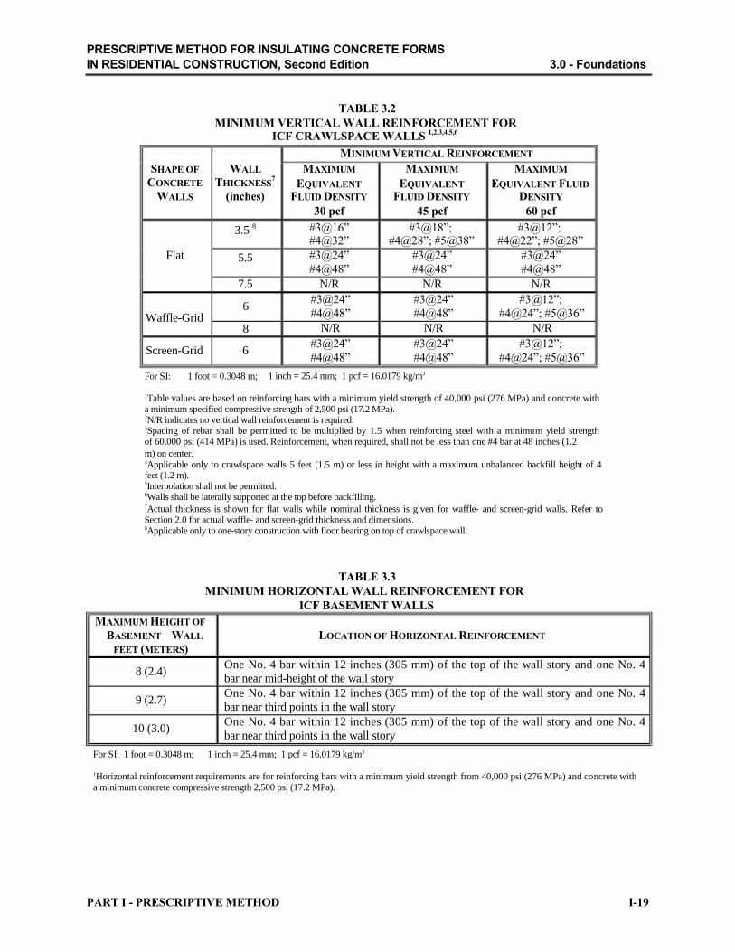
TABLE 3.2
MINIMUM VERTICAL WALL REINFORCEMENT FOR ICF CRAWLSPACE WALLS
1,2,3,4,5,6
MINIMUM VERTICAL REINFORCEMENT
SHAPE OF WALL MAXIMUM MAXIMUM MAXIMUM
CONCRETE THICKNESS7
EQUIVALENT EQUIVALENT EQUIVALENT FLUID
WALLS (inches) FLUID DENSITY FLUID DENSITY DENSITY
30 pcf 45 pcf 60 pcf
3.5 8 #3@16” #3@18”; #3@12”;
#4@32” #4@28”; #5@38” #4@22”; #5@28”
Flat 5.5 #3@24” #3@24” #3@24”
#4@48” #4@48” #4@48”
7.5 N/R N/R N/R
6 Waffle-Grid 8
Screen-Grid 6 For SI: 1 foot = 0.3048 m;
#3@24” #3@24” #3@12”;
#4@48” #4@48” #4@24”; #5@36”
N/R N/R N/R
#3@24” #3@24” #3@12”;
#4@48” #4@48” #4@24”; #5@36”
1 inch = 25.4 mm; 1 pcf = 16.0179 kg/m3
1Table values are based on reinforcing bars with a minimum yield strength of 40,000 psi (276 MPa) and concrete with a minimum specified compressive strength of 2,500 psi (17.2 MPa). 2N/R indicates no vertical wall reinforcement is required. 3Spacing of rebar shall be permitted to be multiplied by 1.5 when reinforcing steel with a minimum yield strength of 60,000 psi (414 MPa) is used. Reinforcement, when required, shall not be less than one #4 bar at 48 inches (1.2
m) on center. 4Applicable only to crawlspace walls 5 feet (1.5 m) or less in height with a maximum unbalanced backfill height of 4 feet (1.2 m). 5Interpolation shall not be permitted. 6Walls shall be laterally supported at the top before backfilling. 7Actual thickness is shown for flat walls while nominal thickness is given for waffle- and screen-grid walls. Refer to Section 2.0 for actual waffle- and screen-grid thickness and dimensions. 8Applicable only to one-story construction with floor bearing on top of crawlspace wall.
TABLE 3.3
MINIMUM HORIZONTAL WALL REINFORCEMENT FOR
ICF BASEMENT WALLS
MAXIMUM HEIGHT OF
BASEMENT WALL
FEET (METERS)
8 (2.4)
9 (2.7)
10 (3.0)
For SI: 1 foot = 0.3048 m;
LOCATION OF HORIZONTAL REINFORCEMENT
One No. 4 bar within 12 inches (305 mm) of the top of the wall story and one No. 4
bar near mid-height of the wall story
One No. 4 bar within 12 inches (305 mm) of the top of the wall story and one No. 4
bar near third points in the wall story
One No. 4 bar within 12 inches (305 mm) of the top of the wall story and one No. 4
bar near third points in the wall story
1 inch = 25.4 mm; 1 pcf = 16.0179 kg/m3
1Horizontal reinforcement requirements are for reinforcing bars with a minimum yield strength from 40,000 psi (276 MPa) and concrete with a minimum concrete compressive strength 2,500 psi (17.2 MPa).
PART I - PRESCRIPTIVE METHOD I-19

PRESCRIPTIVE METHOD FOR INSULATING CONCRETE FORMS
IN RESIDENTIAL CONSTRUCTION, Second Edition 3.0 - Foundations
TABLE 3.4
MINIMUM VERTICAL WALL REINFORCEMENT FOR
5.5-inch- (140-mm-) THICK FLAT ICF BASEMENT WALLS 1,2,3,4,5
MAXIMUM
MAX. WALL UNBALANCED
HEIGHT BACKFILL
(feet) HEIGHT6
(feet)
4
MINIMUM VERTICAL REINFORCEMENT
MAXIMUM MAXIMUM MAXIMUM
EQUIVALENT FLUID EQUIVALENT FLUID EQUIVALENT FLUID
DENSITY DENSITY DENSITY
30 pcf 45 pcf 60 pcf
#4@48” #4@48” #4@48”
#3@12”; #4@22”; #3@8”; #4@14”;
8
5
6
#4@48”
#3@12”; #4@22”;
#5@30”; #6@40”
#5@32”; #6@40” #5@20”; #6@26”
#3@8”; #4@14”; #3@6”; #4@10”;
#5@20”; #6@24” #5@14”; #6@20”
7
4
5
#3@8”; #4@14”;
#5@22”; #6@26”
#4@48”
#4@48”
#3@5”; #4@10”; #3@4”; #4@6”;
#5@14”; #6@18” #5@10”; #6@14”
#4@48” #4@48”
#3@12”; #4@20”; #3@8”; #4@14”;
#5@28”; #6@36” #5@20”; #6@22”
6 #3@10”; #4@20”; #3@6”; #4@12”; #4@8”; 9 #5@28”; #6@34” #5@18”; #6@20” #5@14”; #6@16”
7 #3@8”; #4@14”; #4@8”; #4@6”; #5@20”; #6@22” #5@12”; #6@16” #5@10”; #6@12”
8
4
5
#3@6”; #4@10”;
#5@14”; #6@16”
#4@48”
#4@48”
#4@6”; #4@4”;
#5@10”; #6@12” #5@6”; #6@8”
#4@48” #4@48”
#3@10”; #4@18”; #3@6”; #4@14”;
#5@26”; #6@30” #5@18”; #6@20”
10
6
7
#3@10”; #4@18”;
#5@24”; #6@30”
#3@6”; #4@12”;
#5@16”; #6@18”
#3@6”; #4@12”; #3@4”; #4@8”;
#5@16”; #6@18” #5@12”; #6@14”
#3@4”; #4@8”; #4@6”;
#5@12” #5@8”; #6@10”
8
9
#3@4”; #4@8”;
#5@12”; #6@14”
#3@4”; #4@6”;
#5@10”; #6@12”
#4@6”; #4@4”;
#5@8”; #6@12” #5@6”; #6@8”
#4@4”; #5@4”; #6@6”
#5@6”; #6@8”
For SI: 1 foot = 0.3048 m; 1 inch = 25.4 mm; 1 pcf = 16.0179 kg/m3
1Table values are based on reinforcing bars with a minimum yield strength of 40,000 psi (276 MPa) and concrete with a minimum specified compressive strength of 2,500 psi (17.2 MPa). 2Spacing of rebar shall be permitted to be multiplied by 1.5 when reinforcing steel with a minimum yield strength of 60,000 psi (414 MPa) is used. Reinforcement shall not be less than one #4 bar at 48 inches (1.2 m) on center. 3Deflection criterion is L/240, where L is the height of the basement wall in inches. 4Interpolation shall not be permitted. 5Walls shall be laterally supported at the top before backfilling. 6Refer to Section 1.0 for the definition of unbalanced backfill height.
I-20 PART I - PRESCRIPTIVE METHOD

PRESCRIPTIVE METHOD FOR INSULATING CONCRETE FORMS
IN RESIDENTIAL CONSTRUCTION, Second Edition 3.0 - Foundations
TABLE 3.5
MINIMUM VERTICAL WALL REINFORCEMENT FOR 7.5-inch- (191-mm-) THICK FLAT ICF BASEMENT WALLS
1,2,3,4,5,6
MAX. WALL
HEIGHT
(feet)
8
MAXIMUM
UNBALANCED
BACKFILL HEIGHT7
(feet)
4
5
6
MINIMUM VERTICAL REINFORCEMENT
MAXIMUM MAXIMUM MAXIMUM
EQUIVALENT FLUID EQUIVALENT FLUID EQUIVALENT FLUID
DENSITY DENSITY DENSITY
30 pcf 45 pcf 60 pcf
N/R N/R N/R
N/R N/R N/R
N/R N/R N/R
#4@14”; #4@10”; 7
4
5
6
9
7
N/R
N/R
N/R
N/R
N/R
#5@20”; #6@28”
N/R
N/R
N/R
#4@12”;
#5@18”; #6@26”
#5@16”; #6@20”
N/R
N/R
#4@14”;
#5@20”; #6@28”
#4@8”;
#5@14”; #6@18”
10
8
4
5
6
7
#4@14”; #4@8”;
#5@22”; #6@28” #5@14”; #6@18”
N/R N/R
N/R N/R
N/R N/R
#4@12”; N/R
#5@18”; #6@24”
#4@6”;
#5@10”; #6@14”
N/R
N/R
#4@12”;
#5@18”; #6@26”
#4@8”;
#5@12”; #6@18”
8 #4@12”; #4@8”; #4@6”; #5@20”; #6@26” #5@12”; #6@16” #5@8”; #6@12”
9 #4@10”; #4@6”; #4@4”;
#5@14”; #6@20” #5@10”; #6@12” #5@6”; #6@10”
For SI: 1 foot = 0.3048 m; 1 inch = 25.4 mm; 1 pcf = 16.0179 kg/m3
1Table values are based on reinforcing bars with a minimum yield strength of 40,000 psi (276 MPa) and concrete with a minimum specified compressive strength of 2,500 psi (17.2 MPa). 2Spacing of rebar shall be permitted to be multiplied by 1.5 when reinforcing steel with a minimum yield strength of 60,000 psi (414 MPa) is used. Reinforcement, when required, shall not be less than one #4 bar at 48 inches (1.2 m) on center. 3N/R indicates no reinforcement is required. 4Deflection criterion is L/240, where L is the height of the basement wall in inches. 5Interpolation shall not be permitted. 6Walls shall be laterally supported at the top before backfilling. 7Refer to Section 1.0 for the definition of unbalanced backfill height.
PART I - PRESCRIPTIVE METHOD I-21

PRESCRIPTIVE METHOD FOR INSULATING CONCRETE FORMS
IN RESIDENTIAL CONSTRUCTION, Second Edition 3.0 - Foundations
TABLE 3.6
MINIMUM VERTICAL WALL REINFORCEMENT FOR 9.5-inch- (241-mm-) THICK FLAT ICF BASEMENT WALLS
1,2,3,4,5,6
MAX. WALL
HEIGHT
(feet)
8
9
MAXIMUM
UNBALANCED
BACKFILL HEIGHT7
(feet)
4
5
6
7
4
5
6
MINIMUM VERTICAL REINFORCEMENT
MAXIMUM MAXIMUM MAXIMUM
EQUIVALENT FLUID EQUIVALENT FLUID EQUIVALENT FLUID
DENSITY DENSITY DENSITY
30 pcf 45 pcf 60 pcf
N/R N/R N/R
N/R N/R N/R
N/R N/R N/R
N/R N/R N/R
N/R N/R N/R
N/R N/R N/R
N/R N/R N/R
#4@12”; 7
8
4
5
6
10 7
8
9 For SI: 1 foot = 0.3048 m; 1 inch = 25.4 mm;
N/R
N/R
N/R
N/R
N/R
N/R
N/R
N/R
1 pcf = 16.0179 kg/m3
N/R
#4@12”;
#5@18”; #6@26”
N/R
N/R
N/R
N/R
#4@12”;
#5@16”; #6@24”
#4@8”;
#5@12”; #6@18”
#5@18”; #6@26”
#4@8”;
#5@14”; #6@18”
N/R
N/R
#4@18”;
#5@26”; #6@36”
#4@10”;
#5@18”; #6@24”
#4@8”;
#5@12”; #6@16”
#4@6”;
#5@10”; #6@12”
1Table values are based on reinforcing bars with a minimum yield strength of 40,000 psi (276 MPa) and concrete with a minimum specified compressive strength of 2,500 psi (17.2 MPa). 2Spacing of rebar shall be permitted to be multiplied by 1.5 when reinforcing steel with a minimum yield strength of 60,000 psi (414 MPa) is used. Reinforcement, when required, shall not be less than one #4 bar at 48 inches (1.2 m) on center. 3N/R indicates no reinforcement is required. 4Deflection criterion is L/240, where L is the height of the basement wall in inches. 5Interpolation shall not be permitted. 6Walls shall be laterally supported at the top before backfilling. 7Refer to Section 1.0 for the definition of unbalanced backfill height.
I-22 PART I - PRESCRIPTIVE METHOD

PRESCRIPTIVE METHOD FOR INSULATING CONCRETE FORMS
IN RESIDENTIAL CONSTRUCTION, Second Edition 3.0 - Foundations
TABLE 3.7
MINIMUM VERTICAL WALL REINFORCEMENT FOR 6-inch (152-mm) WAFFLE-GRID ICF BASEMENT WALLS
1,2,3,4,5
MAX. WALL
HEIGHT
(feet)
MAXIMUM
UNBALANCED
BACKFILL HEIGHT6
(feet)
MINIMUM VERTICAL REINFORCEMENT
MAXIMUM MAXIMUM MAXIMUM
EQUIVALENT FLUID EQUIVALENT FLUID EQUIVALENT FLUID
DENSITY DENSITY DENSITY
30 pcf 45 pcf 60 pcf
#4@24”; 4
8 5
6
7
4
5
9 6
7
8
4
5
10 6
7
8
9
For SI: 1 foot = 0.3048 m; 1 inch = 25.4 mm;
#4@48”
#4@12”;
#5@24”
#4@12”;
#5@12”
Design Required
#4@48”
#4@12”
#5@12”;
#6@12”
Design Required
Design Required
#4@48”
#3@12”;
#4@12”
Design Required
Design Required
Design Required
Design Required
1 pcf = 16.0179 kg/m3
#5@24”
#4@12”;
#5@12”
Design Required
Design Required
#4@12”;
#5@24”
#4@12”;
#5@12”
Design Required
Design Required
Design Required
#4@12”;
#5@12”
Design Required
Design Required
Design Required
Design Required
Design Required
#4@12”
Design Required
Design Required
Design Required
#3@12”;
#4@12”
Design Required
Design Required
Design Required
Design Required
#5@12”;
#6@12”
Design Required
Design Required
Design Required
Design Required
Design Required
1Table values are based on reinforcing bars with a minimum yield strength of 40,000 psi (276 MPa) and concrete with a minimum specified compressive strength of 2,500 psi (17.2 MPa). 2Spacing of rebar shall be permitted to be increased by 12 inches (305 mm) when reinforcing steel with a minimum yield strength of 60,000 psi (414 MPa) is used. Reinforcement shall not be less than one #4 bar at 48 inches (1.2 m) on center. 3Deflection criterion is L/240, where L is the height of the basement wall in inches. 4Interpolation shall not be permitted. 5Walls shall be laterally supported at the top before backfilling. 6Refer to Section 1.0 for the definition of unbalanced backfill height.
PART I - PRESCRIPTIVE METHOD I-23

PRESCRIPTIVE METHOD FOR INSULATING CONCRETE FORMS
IN RESIDENTIAL CONSTRUCTION, Second Edition 3.0 - Foundations
TABLE 3.8
MINIMUM VERTICAL WALL REINFORCEMENT FOR 8-inch (203-mm) WAFFLE-GRID ICF BASEMENT WALLS
1, 2, 3,4,5,6
MAX. WALL
HEIGHT
(feet)
MAXIMUM
UNBALANCED
BACKFILL HEIGHT7
(feet)
4
MINIMUM VERTICAL REINFORCEMENT
MAXIMUM MAXIMUM MAXIMUM
EQUIVALENT FLUID EQUIVALENT FLUID EQUIVALENT FLUID
DENSITY DENSITY DENSITY
30 pcf 45 pcf 60 pcf
N/R N/R N/R
#4@24”; #4@12”;
8 5 N/R #5@36”
#5@24”
6 #4@24”; #4@12”; #4@12”;
#5@36” #5@24” #5@12”
7
4
5
9 6
7
8
4
5
10 6
7
8
9 For SI: 1 foot = 0.3048 m; 1 inch = 25.4 mm;
#4@12”;
#5@12”; #6@24”
N/R
N/R
#4@24”;
#5@24”
#4@12”;
#5@24”
#4@12”;
#5@12”
N/R
N/R
#4@12”
#5@24”
#4@12”;
#5@12”
#4@12”;
#5@12”
#5@12”; #6@12”
1 pcf = 16.0179 kg/m3
#4@12”;
#5@12”
N/R
#4@12”;
#5@24”
#4@12”;
#5@12”
#5@12”;
#6@12”
#5@12”;
#6@12”
#4@24”;
#5@24”; #6@36”
#3@12”; #4@24”;
#5@24”; #6@36”
#4@12”;
#5@12”
#5@12”;
#6@12”
#6@12”
Design Required
#5@12”;
#6@12”
N/R
#4@12”;
#5@24”
#4@12”;
#5@12”
#5@12”;
#6@12”
Design Required
#3@12”;
#4@12”; #5@24”
#4@12”;
#5@24”
#5@12”;
#6@12”
#6@12”
Design Required
Design Required
1Table values are based on reinforcing bars with a minimum yield strength of 40,000 psi (276 MPa) and concrete with a minimum specified compressive strength of 2,500 psi (17.2 MPa). 2Spacing of rebar shall be permitted to be increased by 12 inches (305 mm) when reinforcing steel with a minimum yield strength of 60,000 psi
(414 MPa) is used. Reinforcement, when required, shall not be less than one #4 bar at 48 inches (1.2 m) on center. 3N/R indicates no reinforcement is required. 4Deflection criterion is L/240, where L is the height of the basement wall in inches. 5Interpolation shall not be permitted. 6Walls shall be laterally supported at the top before backfilling. 7Refer to Section 1.0 for the definition of unbalanced backfill height.
I-24 PART I - PRESCRIPTIVE METHOD

PRESCRIPTIVE METHOD FOR INSULATING CONCRETE FORMS
IN RESIDENTIAL CONSTRUCTION, Second Edition 3.0 - Foundations
TABLE 3.9
MINIMUM VERTICAL WALL REINFORCEMENT FOR 6-inch (152-mm) SCREEN-GRID ICF BASEMENT WALLS
1,2,3,4,5
MAX. WALL
HEIGHT
(feet)
MAXIMUM
UNBALANCED
BACKFILL HEIGHT6
(feet)
MINIMUM VERTICAL REINFORCEMENT
MAXIMUM MAXIMUM MAXIMUM
EQUIVALENT FLUID EQUIVALENT FLUID EQUIVALENT FLUID
DENSITY DENSITY DENSITY
30 pcf 45 pcf 60 pcf
#3@12”; #3@12”; 4
8 5
6
7
4
5
9 6
7
8
4
5
10 6
7
8
9
For SI: 1 foot = 0.3048 m; 1 inch = 25.4 mm;
#4@48”
#3@12”;
#4@24”; #5@24”
#4@12”;
#5@12”
Design Required
#4@48”
#3@12”;
#4@12”; #5@24”
#4@12”;
#5@12”
Design Required
Design Required
#4@48”
#3@12”;
#4@12”
#4@12”;
#5@12”
Design Required
Design Required
Design Required
1 pcf = 16.0179 kg/m3
#4@24”; #5@36”
#3@12”;
#4@12”
#5@12”;
#6@12”
Design Required
#3@12”;
#4@24”; #5@24”
#4@12”; #5@12”
Design Required
Design Required
Design Required
#3@12”; #4@12”;
#5@24”; #6@24”
#4@12”;
#5@12”
Design Required
Design Required
Design Required
Design Required
#4@12”; #5@24”
#4@12”;
#5@12”
Design Required
Design Required
#3@12”; #4@12”;
#5@12”; #6@24”
Design Required
Design Required
Design Required
Design Required
#3@12”;
#4@12”
Design Required
Design Required
Design Required
Design Required
Design Required
1Table values are based on reinforcing bars with a minimum yield strength of 40,000 psi (276 MPa) and concrete with a minimum specified compressive strength of 2,500 psi (17.2 MPa). 2Spacing of rebar in shaded cells shall be permitted to be increased by 12 inches (305 mm) when reinforcing steel with a minimum yield strength of 60,000 psi (414 MPa) is used. Reinforcement shall not be less than one #4 bar at 48 inches (1.2 m) on center. 3Deflection criterion is L/240, where L is the height of the basement wall in inches. 4Interpolation shall not be permitted. 5Walls shall be laterally supported at the top before backfilling. 6Refer to Section 1.0 for the definition of unbalanced backfill height.
PART I - PRESCRIPTIVE METHOD I-25

PRESCRIPTIVE METHOD FOR INSULATING CONCRETE FORMS
IN RESIDENTIAL CONSTRUCTION, Second Edition 3.0 - Foundations
Figure 3.1 ICF Stem Wall and Monolithic Slab-on-Grade Construction
I-26 PART I - PRESCRIPTIVE METHOD

PRESCRIPTIVE METHOD FOR INSULATING CONCRETE FORMS
IN RESIDENTIAL CONSTRUCTION, Second Edition 3.0 - Foundations
PART I - PRESCRIPTIVE METHOD I-27

PRESCRIPTIVE METHOD FOR INSULATING CONCRETE FORMS
IN RESIDENTIAL CONSTRUCTION, Second Edition 3.0 - Foundations
Figure 3.2 ICF Crawlspace Wall Construction
I-28 PART I - PRESCRIPTIVE METHOD

PRESCRIPTIVE METHOD FOR INSULATING CONCRETE FORMS
IN RESIDENTIAL CONSTRUCTION, Second Edition 3.0 - Foundations
Figure 3.3 ICF Basement Wall Construction
PART I - PRESCRIPTIVE METHOD I-29

PRESCRIPTIVE METHOD FOR INSULATING CONCRETE FORMS
IN RESIDENTIAL CONSTRUCTION, Second Edition 4.0 - ICF Above-Grade Walls
4.0 ICF Above-Grade Walls
4.1 ICF Above-Grade Wall Requirements
ICF above-grade walls shall be constructed in accordance with Figures 4.1, 4.2, or 4.3 and this
section. The minimum length of ICF wall without openings, reinforcement around openings, and
lintel requirements above wall openings shall be in accordance with Section 5.0. Lateral support for
above-grade ICF walls shall be provided by the roof and floor framing systems in accordance with
Section 6.0. The minimum wall thickness shall be greater than or equal to the wall thickness of the
wall above.
Design wind pressures of Table 4.1 shall be used to determine the vertical wall reinforcement
requirements in Tables 4.2, 4.3, and 4.4. The minimum vertical reinforcement shall be one No. 4
rebar (Grade 40) at 48 inches (1.2 m) on center and at all inside and outside corners of exterior ICF
walls. Horizontal wall reinforcement shall be required in the form of one No. 4 rebar within 12
inches (305 mm) from the top of the wall, one No. 4 rebar within 12 inches (305 mm) from the
finish floor, and one No. 4 rebar near one-third points throughout the remainder of the wall.
In Seismic Design Category C, the minimum vertical and horizontal reinforcement shall be one No.
5 rebar at 24 inches (610 m) on center. In Seismic Design Categories D1 and D2, the minimum vertical and horizontal reinforcement shall be one No. 5 rebar at a maximum spacing of 18 inches (457 mm) on center and the minimum concrete compressive strength shall be 3,000 psi (20.5 MPa).
For design wind pressure greater than 40 psf (1.9 kPa) or Seismic Design Category C or greater,
all vertical wall reinforcement in the top-most ICF story shall be terminated with a 90 degree bend.
The bend shall result in a minimum length of 6 inches (152 mm) parallel to the horizontal wall
reinforcement and lie within 4 inches (102 mm) of the top surface of the ICF wall. In addition,
horizontal wall reinforcement at exterior building corners shall be terminated with a 90 degree bend
resulting in a minimum lap splice length of 40db with the horizontal reinforcement in the
intersecting wall. The radius of bends shall not be less than 4 inches (102 mm).
Exception: In lieu of bending horizontal or vertical reinforcement, separate bent
reinforcement bars shall be permitted provided that the minimum lap splice with vertical and
horizontal wall reinforcement is not less than 40db.
4.2 ICF Above-Grade Wall Coverings
4.2.1 Interior Covering
Rigid foam plastic on the interior of habitable spaces shall be covered with a minimum of 1/2-inch
(13-mm) gypsum board or an approved finish material that provides a thermal barrier to limit the
average temperature rise of the unexposed surface to no more than 250 degrees F (139 degrees C)
after 15 minutes of fire exposure in accordance with ASTM E 119 [19]. The use of vapor retarders and
air barriers shall be in accordance with the authority having jurisdiction.
I-30 PART I - PRESCRIPTIVE METHOD

PRESCRIPTIVE METHOD FOR INSULATING CONCRETE FORMS
IN RESIDENTIAL CONSTRUCTION, Second Edition 4.0 - ICF Above-Grade Walls
4.2.2 Exterior Covering
ICFs constructed of rigid foam plastics shall be protected from sunlight and physical damage by the
application of an approved exterior covering. All ICFs shall be covered with approved materials
installed to provide a barrier against the weather. Use of air barriers and vapor retarders shall be in accordance with the authority having jurisdiction.
TABLE 4.1
DESIGN WIND PRESSURE FOR USE WITH MINIMUM VERTICAL WALL REINFORCEMENT
TABLES FOR ABOVE GRADE WALLS1
DESIGN WIND PRESSURE (psf)
WIND ENCLOSED2
PARTIALLY ENCLOSED2
SPEED Exposure3 Exposure3
(mph) B C D B C D
85 18 24 29 23 31 37
90 20 27 32 25 35 41
100 24 34 39 31 43 51
110 29 41 48 38 52 61
120 35 48 57 45 62 73
130 41 56 66 53 73 854
140 47 65 77 61 844
994
150 54 75 884
70 964
1144
For SI: 1 psf = 0.0479 kN/m2; 1 mph = 1.6093 km/hr
1This table is based on ASCE 7-98 components and cladding wind pressures using a mean roof height of 35 ft (10.7 m) and a tributary area of 10 ft2 (0.9 m2). 2Enclosure Classifications are as defined in Section 1.5. 3Exposure Categories are as defined in Section 1.5. 4For wind pressures greater than 80 psf (3.8 kN/m2), design is required in accordance with accepted practice and approved manufacturer guidelines.
PART I - PRESCRIPTIVE METHOD I-31

PRESCRIPTIVE METHOD FOR INSULATING CONCRETE FORMS
IN RESIDENTIAL CONSTRUCTION, Second Edition 4.0 - ICF Above-Grade Walls
TABLE 4.2
MINIMUM VERTICAL WALL REINFORCEMENT FOR FLAT ICF ABOVE-GRADE WALLS
1,2,3
DESIGN MAXIMUM
WIND WALL
PRESSURE HEIGHT
(TABLE 4.1) PER STORY
(psf) (feet)
8
20 9
10
8
MINIMUM VERTICAL REINFORCEMENT4,5
SUPPORTING ROOF OR SUPPORTING LIGHT- SUPPORTING ICF SECOND
NON-LOAD BEARING FRAME SECOND STORY STORY AND LIGHT-FRAME
WALL AND ROOF ROOF
MINIMUM WALL THICKNESS (inches)
3.5 5.5 3.5 5.5 3.5 5.5
#4@48 #4@48 #4@48 #4@48 #4@48 #4@48
#4@48 #4@48 #4@48 #4@48 #4@48 #4@48
#4@38 #4@48 #4@40 #4@48 #4@42 #4@48
#4@42 #4@48 #4@46 #4@48 #4@48 #4@48
#4@32; #4@34; #4@34; 30 9
10
8
40 9
10
8
50 9
#5@48
Design
Required
#4@30;
#5@48
Design
Required
Design
Required
#4@20;
#5@30
Design
Required
#4@48
#4@48
#4@48
#4@42
#4@32;
#5@48
#4@42
#4@34;
#5@48
#4@48 #5@48 Design
#4@48 Required
#4@30; #4@48 #5@48
Design #4@46 Required
Design #4@34;
Required #5@48
#4@22; #4@46 #5@34
Design #4@34;
Required #5@48
#4@48 #5@48 Design
#4@48 Required
#4@32; #4@48 #5@48
Design #4@48 Required
Design #4@38 Required
#4@24; #4@48 #5@36
Design #4@38 Required
10
8
60 9
Design #4@26;
Required #5@38
Design #4@34;
Required #5@48
Design #4@26;
Required #5@38
Design #4@26;
Required #5@38
Design #4@36 Required
Design #4@28;
Required #5@46
Design #4@28;
Required #5@46
Design #4@40 Required
Design #4@34;
Required #5@48
10 Design #4@22; Design #4@22; Design #4@26;
Required #5@34 Required #5@34 Required #5@38
8
70 9
Design #4@28;
Required #5@46
Design #4@22;
Required #5@34
Design #4@30;
Required #5@48
Design #4@22;
Required #5@34
Design #4@34;
Required #5@48
Design #4@24;
Required #5@36
10 Design #4@16; Design #4@18; Design #4@20;
Required #5@26 Required #5@28 Required #5@30
8
80 9
Design #4@26;
Required #5@38
Design #4@20;
Required #5@30
Design #4@26;
Required #5@38
Design #4@20;
Required #5@30
Design #4@28;
Required #5@46
Design #4@21;
Required #5@34
10 Design #4@14; Design #4@14; Design #4@16;
Required #5@24 Required #5@24 Required #5@26
For SI: 1 foot = 0.3048 m; 1 inch = 25.4 mm; 1 mph = 1.6093 km/hr
1This table is based on reinforcing bars with a minimum yield strength of 40,000 psi (276 MPa) and concrete with a minimum specified compressive strength of 2,500 psi (17.2 MPa). 2Deflection criterion is L/240, where L is the height of the wall story in inches. 3Interpolation shall not be permitted. 4Reinforcement spacing for 3.5 inch (88.9 mm) walls shall be permitted to be multiplied by 1.6 when reinforcing steel with a minimum yield strength of 60,000 psi (414 MPa) is used. Reinforcement shall not be less than one #4 bar at 48 inches (1.2 m) on center. 5Reinforcement spacing for 5.5 inch (139.7 mm) walls shall be permitted to be multiplied by 1.5 when reinforcing steel with a minimum yield strength of 60,000 psi (414 MPa) is used. Reinforcement shall not be less than one #4 bar at 48 inches (1.2 m) on center.
I-32 PART I - PRESCRIPTIVE METHOD

PRESCRIPTIVE METHOD FOR INSULATING CONCRETE FORMS
IN RESIDENTIAL CONSTRUCTION, Second Edition 4.0 - ICF Above-Grade Walls
TABLE 4.3
MINIMUM VERTICAL WALL REINFORCEMENT FOR WAFFLE-GRID ICF ABOVE-GRADE WALLS
1,2,3
DESIGN MAXIMUM
WIND WALL
PRESSURE HEIGHT
(TABLE 4.1) PER STORY
(psf) (feet)
8
20 9
10
8
30 9
MINIMUM VERTICAL REINFORCEMENT4
SUPPORTING ROOF OR SUPPORTING LIGHT- SUPPORTING ICF SECOND
NON-LOAD BEARING FRAME SECOND STORY STORY AND LIGHT-FRAME
WALL AND ROOF ROOF
MINIMUM WALL THICKNESS (inches)
6 8 6 8 6 8
#4@48 #4@48 #4@48 #4@48 #4@48 #4@48
#4@48 #4@48 #4@48 #4@48 #4@48 #4@48
#4@48 #4@48 #4@48 #4@48 #4@48 #4@48
#4@48 #4@48 #4@48 #4@48 #4@48 #4@48
#4@48 #4@48 #4@48 #4@48 #4@48 #4@48
#4@36; #4@36; #4@36; 10
8
40 9
10
8
50 9
10
8
60 9
10
8
70 9
#5@48
#4@36;
#5@48
#4@36;
#5@48
#4@24;
#5@36
#4@36;
#5@48
#4@24;
#5@36
Design
Required
#4@24;
#5@36
Design
Required
Design
Required
#4@24;
#5@36
Design
Required
#4@48
#4@48
#4@48
#4@36;
#5@48
#4@48
#4@36;
#5@48
#4@36;
#5@48
#4@48
#4@36;
#5@48
#4@24;
#5@36
#4@36;
#5@48
#4@24;
#5@36
#4@48 #5@48
#4@48 #4@48
#4@36; #4@48 #5@48
#4@24; #4@48 #5@36
#4@36; #4@48 #5@48
#4@24; #4@48 #5@36
Design #4@36;
Required #5@48
#4@24; #4@48 #5@36
Design #4@36;
Required #5@48
Design #4@24;
Required #5@36
#4@24; #4@36;
#5@36 #5@48
Design #4@24; Required #5@48
#4@48 #5@48
#4@48 #4@48
#4@36; #4@48 #5@48
#4@24; #4@48 #5@36
#4@36; #4@48 #5@48
#4@24; #4@48 #5@48
Design #4@36;
Required #5@48
#4@24; #4@48 #5@48
Design #4@36; Required #5@48
Design #4@24;
Required #5@48
#4@24; #4@48 #5@36
Design #4@24;
Required #5@48
10 Design #4@12; Design #4@24; Design #4@24;
Required #5@36 Required #5@36 Required #5@36
8
80 9
10
For SI: 1 foot = 0.3048 m;
#4@12;
#5@24
Design
Required
Design
Required
1 inch = 25.4 mm;
#4@24; #4@12;
#5@48 #5@24
#4@24; Design #5@36 Required
#4@12; Design
#5@24 Required
1 mph = 1.6093 km/hr
#4@24;
#5@48
#4@24;
#5@36
#4@12;
#5@24
#4@12; #4@36;
#5@24 #5@48
Design #4@24; Required #5@36
Design #4@12;
Required #5@24
1This table is based on reinforcing bars with a minimum yield strength of 40,000 psi (276 MPa) and concrete with a minimum specified compressive strength of 2,500 psi (17.2 MPa). 2Deflection criterion is L/240, where L is the height of the wall story in inches. 3Interpolation shall not be permitted. 4Reinforcement spacing shall be permitted to be increased by 12 inches (305 mm) when reinforcing steel with a minimum yield strength of 60,000 psi (414 MPa) is used or #4 reinforcing bars shall be permitted to be substituted for #5 bars when reinfor cing steel with a minimum yield strength of 60,000 psi (414 MPa) is used with the same spacing. Reinforcement shall not be less than one #4 bar at 48 inches (1.2 m) on center.
PART I - PRESCRIPTIVE METHOD I-33

PRESCRIPTIVE METHOD FOR INSULATING CONCRETE FORMS
IN RESIDENTIAL CONSTRUCTION, Second Edition 4.0 - ICF Above-Grade Walls
TABLE 4.4
MINIMUM VERTICAL WALL REINFORCEMENT FOR SCREEN-GRID ICF ABOVE-GRADE WALLS
1,2,3
MINIMUM VERTICAL REINFORCEMENT4
DESIGN MAXIMUM
WIND WALL
PRESSURE HEIGHT PER
(TABLE 4.1) STORY
(psf) (feet)
SUPPORTING ROOF OR
NON-LOAD BEARING
WALL
SUPPORTING LIGHT- SUPPORTING ICF
FRAME SECOND SECOND STORY AND
STORY AND ROOF LIGHT-FRAME ROOF
MINIMUM WALL THICKNESS (inches)
6 6 6
8 #4@48 #4@48 #4@48
20 9 #4@48 #4@48 #4@48
10 #4@48 #4@48 #4@48
8 #4@48 #4@48 #4@48
30 9 #4@48 #4@48 #4@48
10 #4@36; #5@48 #4@48 #4@48
8 #4@48 #4@48 #4@48
40 9 #4@36; #5@48 #4@36; #5@48 #4@48
10 #4@24; #5@48 #4@24; #5@48 #4@24; #5@48
8 #4@36; #5@48 #4@36; #5@48 #4@48
50 9 #4@24; #5@48 #4@24; #5@48 #4@24; #5@48
10 Design Required Design Required Design Required
8 #4@24; #5@48 #4@24; #5@48 #4@36; #5@48
60 9 #4@24; #5@36 #4@24; #5@36 #4@24; #5@36
10 Design Required Design Required Design Required
8 #4@24; #5@36 #4@24; #5@36 #4@24; #5@36
70 9 Design Required Design Required Design Required
10 Design Required Design Required Design Required
8 #4@12; #5@36 #4@24; #5@36 #4@24; #5@36
80 9 Design Required Design Required Design Required
10 Design Required Design Required Design Required
For SI: 1 foot = 0.3048 m; 1 inch = 25.4 mm; 1 mph = 1.6093 km/hr 1This table is based on reinforcing bars with a minimum yield strength of 40,000 psi (276 MPa) and concrete with a minimum specified compressive strength of 2,500 psi (17.2 MPa). 2Deflection criterion is L/240, where L is the height of the wall story in inches. 3Interpolation shall not be permitted. 4Reinforcement spacing shall be permitted to be increased by 12 inches (305 mm) when reinforcing steel with a
minimum yield strength of 60,000 psi (414 MPa) is used. Reinforcement shall not be less than one #4 bar at 48
inches (1.2 m) on center.
I-34 PART I - PRESCRIPTIVE METHOD

PRESCRIPTIVE METHOD FOR INSULATING CONCRETE FORMS
IN RESIDENTIAL CONSTRUCTION, Second Edition 4.0 - ICF Above-Grade Walls
Figure 4.1 ICF Wall Supporting Light-Frame Roof
PART I - PRESCRIPTIVE METHOD I-35

PRESCRIPTIVE METHOD FOR INSULATING CONCRETE FORMS
IN RESIDENTIAL CONSTRUCTION, Second Edition 4.0 - ICF Above-Grade Walls
Figure 4.2 ICF Wall Supporting Light-Frame Second Story and Roof
I-36 PART I - PRESCRIPTIVE METHOD

PRESCRIPTIVE METHOD FOR INSULATING CONCRETE FORMS
IN RESIDENTIAL CONSTRUCTION, Second Edition 4.0 - ICF Above-Grade Walls
Figure 4.3 ICF Wall Supporting ICF Second Story and Light-Frame Roof
PART I - PRESCRIPTIVE METHOD I-37

PRESCRIPTIVE METHOD FOR INSULATING CONCRETE FORMS
IN RESIDENTIAL CONSTRUCTION, Second Edition 5.0 - ICF Wall Opening Requirements
5.0 ICF Wall Opening Requirements
5.1 Minimum Length of ICF Wall without Openings
The wind velocity pressures of Table 5.1 shall be used to determine the minimum amount of solid wall length in accordance with Tables 5.2 through 5.4 and Figure 5.1. Table 5.5 shall be used to
determine the minimum amount of solid wall length for Seismic Design Categories C, D1, and D2. The greater amount of solid wall length required by Tables 5.2 through 5.5 shall apply.
The amount of solid wall length shall include only those solid wall segments that are a minimum of
24 inches (610 mm) in length. The maximum allowable spacing of wall segments at least 24 inches
(610 mm) in length shall be 18 feet (5.5 m) on center. A minimum length of 24 inches (610 mm) of solid wall segment, extending the full height of each wall story, shall occur at all interior and
exterior corners of exterior walls.
For Seismic Design Categories D1 and D2, the amount of solid wall length shall include only those
solid wall segments that are a minimum of 48 inches (1.2 mm) in length. A minimum length of 24
inches (610 mm) of solid wall segment, extending the full height of each wall story, shall occur at all
interior and exterior corners of exterior walls. The minimum nominal wall thickness shall be 5.5 inches
(140 mm) for all wall types.
5.2 Reinforcement around Openings
Openings in ICF walls shall be reinforced in accordance with Table 5.6 and Figure 5.2 in addition to the minimum wall reinforcement of Sections 3 and 4. Wall openings shall have a minimum depth of concrete over the length of the opening of 8 inches (203 mm) in flat and waffle-grid ICF walls and
12 inches (305 mm) in screen-grid ICF wall lintels. Wall openings in waffle- and screen-grid ICF
walls shall be located such that no less than one-half of a vertical core occurs along each side of the
opening.
Exception: Continuous horizontal wall reinforcement placed within 12 (305 mm)
inches of the top of the wall story as required in Sections 3.0 and 4.0 is permitted to be
used in lieu of top or bottom lintel reinforcement provided that the continuous horizontal wall
reinforcement meets the location requirements specified in Figures 5.3, 5.4, and 5.5 and the
size requirements specified in Tables 5.7 through 5.14.
All opening reinforcement placed horizontally above or below an opening shall extend a minimum of
24 inches (610 mm) beyond the limits of the opening. Where 24 inches (610 mm) cannot be
obtained beyond the limit of the opening, the bar shall be bent 90 degrees in order to obtain a
minimum 12-inch (305-mm) embedment.
I-38 PART I - PRESCRIPTIVE METHOD

PRESCRIPTIVE METHOD FOR INSULATING CONCRETE FORMS
IN RESIDENTIAL CONSTRUCTION, Second Edition 5.0 - ICF Wall Opening Requirements
5.3 Lintels
5.3.1 Load-Bearing ICF Wall Lintels
Lintels shall be provided in load-bearing walls over all openings greater than or equal to 2 feet (0.6
m) in width. Lintels without stirrup reinforcement shall be permitted for flat or waffle-grid ICF
construction in load-bearing walls in accordance with Table 5.7. Lintels with stirrups for flat ICF
walls shall be constructed in accordance with Figure 5.3 and Tables 5.8A and 5.8B. Lintels with
stirrups for waffle-grid ICF walls shall be constructed in accordance with Figure 5.4 and Tables 5.9A and 5.9B. Lintels for screen-grid ICF walls shall be constructed in accordance with Figure
5.5 and Tables 5.10A and 5.10B. Lintel construction in accordance with Figure 5.3 and Tables
5.8A and 5.8B shall be permitted to be used with waffle-grid and screen-grid ICF wall
construction. Lintels spanning between 12 feet - 3 inches (3.7 m) to 16 feet - 3 inches (5.0 m)
shall be constructed in accordance with Table 5.11.
When required, No. 3 stirrups shall be installed in lintels at a maximum spacing of d/2 where d
equals the depth of the lintel, D, less the bottom cover of the concrete as shown in Figures 5.3,
5.4, and 5.5. For flat and waffle-grid lintels, stirrups shall not be required in the middle portion of the
span, A, in accordance with Figure 5.2 and Tables 5.12 and 5.13.
5.3.2 ICF Lintels Without Stirrups in Non Load-Bearing Walls
Lintels shall be provided in non-load bearing walls over all openings greater than or equal to 2 feet (0.6 m) in length in accordance with Table 5.14. Stirrups shall not be required for lintels in gable end walls with spans less than or equal to those listed in Table 5.14.
TABLE 5.1
WIND VELOCITY PRESSURE FOR DETERMINATION OF MINIMUM SOLID WALL LENGTH
1
WIND VELOCITY PRESSURE (psf)
SPEED Exposure2
(mph) B C D
85 14 19 23
90 16 21 25
100 19 26 31
110 23 32 37
120 27 38 44
130 32 44 52
140 37 51 60
150 43 59 693
For SI: 1 psf = 0.0479 kN/m2; 1 mph = 1.6093 km/hr 1Table values are based on ASCE 7-98 Figure 6-4 wind velocity pressures for low-rise buildings using a mean roof height of 35 ft (10.7 m). 2Exposure Categories are as defined in Section 1.5. 3Design is required in accordance with acceptable practice and approved
manufacturer guidelines.
PART I - PRESCRIPTIVE METHOD I-39

PRESCRIPTIVE METHOD FOR INSULATING CONCRETE FORMS
IN RESIDENTIAL CONSTRUCTION, Second Edition 5.0 - ICF Wall Opening Requirements
TABLE 5.2A
MINIMUM SOLID END WALL LENGTH
REQUIREMENTS FOR FLAT ICF WALLS
(WIND PERPENDICULAR TO RIDGE)1,2,3,4,5
DESIGN VELOCITY PRESSURE (psf) 20 25 30 35 40 45 50 60
BUILDING
WALL SIDE WALL ROOF
CATEGORY LENGTH, L SLOPE
(feet)
MINIMUM SOLID WALL LENGTH ON BUILDING END WALL (feet)
≤ 1:12 4.00 4.00 4.00 4.00 4.00 4.00 4.00 4.00
16 5:12 4.00 4.00 4.00 4.00 4.00 4.00 4.25 4.50
7:124
4.00 4.25 4.25 4.50 4.75 4.75 5.00 5.50
12:124
4.25 4.50 4.75 5.00 5.25 5.50 5.75 6.25
≤ 1:12 4.00 4.00 4.00 4.00 4.00 4.00 4.25 4.50
24 5:12 4.00 4.00 4.00 4.25 4.25 4.50 4.50 4.75
7:124
4.25 4.50 4.75 5.00 5.25 5.50 5.75 6.25
12:124
4.75 5.00 5.25 5.75 6.00 6.50 6.75 7.50
≤ 1:12 4.00 4.00 4.00 4.00 4.25 4.25 4.50 4.75
32
One-Story or
Top Story of
Two-Story
40
5:12
7:124
12:124
≤ 1:12
5:12
7:124
12:124
4.00 4.00 4.25
4.50 5.00 5.25
5.00 5.50 6.00
4.00 4.00 4.25
4.00 4.25 4.50
4.75 5.25 5.75
5.50 6.00 6.50
4.50 4.50 4.75 5.00 5.25
5.50 6.00 6.25 6.50 7.25
6.50 7.00 7.25 7.75 8.75
4.25 4.50 4.50 4.75 5.00
4.75 4.75 5.00 5.25 5.50
6.00 6.50 7.00 7.25 8.00
7.25 7.75 8.25 8.75 10.00
≤ 1:12 4.00 4.25 4.25 4.50 4.75 4.75 5.00 5.50
50 5:12 4.25 4.50 4.75 5.00 5.25 5.50 5.75 6.00
7:124
5.25 5.75 6.25 6.75 7.25 7.75 8.25 9.25
12:124
6.00 6.75 7.50 8.00 8.75 9.50 10.25 11.50
≤ 1:12 4.00 4.25 4.50 4.75 5.00 5.25 5.25 5.75
60 5:12 4.50 4.75 5.00 5.25 5.50 5.75 6.00 6.75
7:124
5.50 6.25 6.75 7.50 8.00 8.50 9.25 10.25
12:124
6.50 7.25 8.25 9.00 9.75 10.50 11.50 13.00
For SI: 1 foot = 0.3048 m; 1 inch = 25.4 mm; 1 psf = 0.0479 kN/m2
1Table values are based on reinforcing bars with a minimum yield strength of 40,000 psi (276 MPa) and concrete with a minimum specified
compressive strength of 2,500 psi (17.2 MPa). 2Table values are based on a 3.5 in (88.9 mm) thick flat wall. For a 5.5 in (139.7 mm) thick flat wall, multiply the table values by 0.9. The adjusted values shall not result in solid wall lengths less than 4 ft. 3Table values are based on a maximum unsupported wall height of 10 ft (3.0 m). 4Values are based on a 30 feet (9.1 m) building end wall width. For a 45 ft (13.7 m) building end wall and roof pitches greater than 7:12, multiply the
table values by 1.2. For a 60 ft (18.3 m) building end wall and roof pitches greater than 7:12, multiply the table values by 1.4. 5Linear interpolation shall be permitted.
I-40 PART I - PRESCRIPTIVE METHOD

PRESCRIPTIVE METHOD FOR INSULATING CONCRETE FORMS
IN RESIDENTIAL CONSTRUCTION, Second Edition 5.0 - ICF Wall Opening Requirements
TABLE 5.2B
MINIMUM SOLID END WALL LENGTH
REQUIREMENTS FOR FLAT ICF WALLS
(WIND PERPENDICULAR TO RIDGE)1,2,3,4,5
DESIGN VELOCITY PRESSURE (psf) 20 25 30 35 40 45 50 60
BUILDING
WALL SIDE WALL ROOF
CATEGORY LENGTH, L SLOPE
(feet)
MINIMUM SOLID WALL LENGTH ON BUILDING END WALL (feet)
≤ 1:12 4.00 4.25 4.50 4.75 5.00 5.25 5.25 5.75
16 5:12 4.50 4.75 5.00 5.25 5.50 5.75 6.00 6.75
7:124
4.50 5.00 5.25 5.75 6.00 6.25 6.75 7.25
12:124
5.00 5.25 5.75 6.25 6.50 7.00 7.25 8.25
≤ 1:12 4.50 4.75 5.00 5.25 5.50 5.75 6.00 6.75
24 5:12 4.75 5.25 5.50 6.00 6.25 6.75 7.00 7.75
7:124
5.25 5.75 6.25 6.75 7.00 7.50 8.00 9.00
12:124
5.50 6.25 6.75 7.25 8.00 8.50 9.00 10.25
≤ 1:12 4.75 5.00 5.50 5.75 6.25 6.50 6.75 7.50
32
First Story of
Two-Story
40
5:12
7:124
12:124
≤ 1:12
5:12
7:124
12:124
5.25 5.75 6.25
5.75 6.50 7.00
6.25 7.00 7.75
5.00 5.50 5.75
5.50 6.25 6.75
6.25 7.00 7.75
7.00 8.00 8.75
6.75 7.25 7.50 8.00 9.00
7.75 8.25 9.00 9.50 10.75
8.50 9.25 10.00 10.75 12.25
6.25 6.75 7.25 7.50 8.50
7.25 8.00 8.50 9.00 10.25
8.75 9.50 10.25 11.00 12.50
9.75 10.75 11.50 12.50 14.25
≤ 1:12 5.50 6.00 6.50 7.00 7.50 8.00 8.50 9.50
50 5:12 6.00 6.75 7.50 8.25 9.00 9.75 10.50 11.75
7:124
7.00 8.00 9.00 10.00 10.75 11.75 12.75 14.50
12:124
7.75 9.00 10.00 11.25 12.25 13.50 14.75 17.00
≤ 1:12 5.75 6.50 7.00 7.50 8.25 8.75 9.50 10.75
60 5:12 6.75 7.50 8.25 9.25 10.00 10.75 11.75 13.25
7:124
7.75 9.00 10.00 11.00 12.25 13.25 14.50 16.75
12:124
8.75 10.00 11.50 12.75 14.00 15.50 16.75 19.50
For SI: 1 foot = 0.3048 m; 1 inch = 25.4 mm; 1 psf = 0.0479 kN/m2
1Table values are based on reinforcing bars with a minimum yield strength of 40,000 psi (276 MPa) and concrete with a minimum specified
compressive strength of 2,500 psi (17.2 MPa). 2Table values are based on a 3.5 in (88.9 mm) thick flat wall. For a 5.5 in (139.7 mm) thick flat wall, multiply the table values by 0.9. The adjusted values shall not result in solid wall lengths less than 4 ft. 3Table values are based on a maximum unsupported wall height of 10 ft (3.0 m). 4Values are based on a 30 feet (9.1 m) building end wall width. For a 45 ft (13.7 m) building end wall and roof pitches greater than 7:12, multiply the
table values by 1.2. For a 60 ft (18.3 m) building end wall and roof pitches greater than 7:12, multiply the table values by 1.4. 5Linear interpolation shall be permitted.
PART I - PRESCRIPTIVE METHOD I-41

PRESCRIPTIVE METHOD FOR INSULATING CONCRETE FORMS
IN RESIDENTIAL CONSTRUCTION, Second Edition 5.0 - ICF Wall Opening Requirements
TABLE 5.2C
MINIMUM SOLID SIDE WALL LENGTH
REQUIREMENTS FOR FLAT ICF WALLS
(WIND PARALLEL TO RIDGE)1,2,3,4,5
DESIGN VELOCITY PRESSURE (psf) 20 25 30 35 40 45 50 60
WALL
CATEGORY
BUILDING END
WALL WIDTH, W MINIMUM SOLID WALL LENGTH ON BUILDING SIDE WALL (feet)
(feet)
16 4.00 4.00 4.00 4.00 4.25 4.25 4.50 4.75
One-Story or
Top Story of
Two-Story
24 4.00 4.25
32 4.50 4.75
40 5.00 5.50
50 5.75 6.25
4.50 4.75 4.75 5.00 5.25 5.50
5.00 5.25 5.50 6.00 6.25 6.75
5.75 6.25 6.75 7.00 7.50 8.25
7.00 7.50 8.25 8.75 9.50 10.75
60 6.50 7.50 8.25 9.25 10.00 10.75 11.75 13.25
16 4.25 4.50 4.75 5.00 5.25 5.50 5.75 6.50
24 4.75 5.25 5.50 6.00 6.25 6.75 7.00 8.00
First Story of 32 5.50 6.00 6.50 7.00 7.50 8.00 8.75 9.75
Two-Story 40 6.25 7.00 7.50 8.25 9.00 9.75 10.50 12.00
50 7.25 8.25 9.25 10.25 11.25 12.25 13.25 15.25
60 8.50 9.75 11.00 12.25 13.50 15.00 16.25 18.75
For SI: 1 foot = 0.3048 m; 1 inch = 25.4 mm; 1 psf = 0.0479 kN/m2
1Table values are based on reinforcing bars with a minimum yield strength of 40,000 psi (276 MPa) and concrete with a minimum specified
compressive strength of 2,500 psi (17.2 MPa). 2Table values are based on a 3.5 in (88.9 mm) thick flat wall. For a 5.5 in (139.7 mm) thick flat wall, multiply the table values by 0.9. The adjusted values may not result in solid wall lengths less than 4 ft. 3Table values are based on a maximum unsupported wall height of 10 ft (3.0 m). 4Table values are based on a maximum 12:12 roof pitch. 5Linear interpolation shall be permitted.
I-42 PART I - PRESCRIPTIVE METHOD

PRESCRIPTIVE METHOD FOR INSULATING CONCRETE FORMS
IN RESIDENTIAL CONSTRUCTION, Second Edition 5.0 - ICF Wall Opening Requirements
TABLE 5.3A
MINIMUM SOLID END WALL LENGTH
REQUIREMENTS FOR WAFFLE-GRID ICF WALLS
(WIND PERPENDICULAR TO RIDGE) 1,2,5,4,5
DESIGN VELOCITY PRESSURE (psf) 20 25 30 35 40 45 50 60
BUILDING
WALL SIDE WALL ROOF
CATEGORY LENGTH, L SLOPE
(feet)
MINIMUM SOLID WALL LENGTH ON BUILDING END WALL (feet)
≤ 1:12 4.00 4.00 4.00 4.00 4.00 4.00 4.00 4.25
16 5:12 4.00 4.00 4.00 4.00 4.25 4.25 4.50 4.75
7:124
4.00 4.25 4.50 4.75 5.00 5.25 5.50 6.00
12:124
4.50 4.75 5.00 5.50 5.75 6.00 6.50 7.00
≤ 1:12 4.00 4.00 4.00 4.00 4.25 4.25 4.50 4.75
24 5:12 4.00 4.00 4.25 4.25 4.50 4.75 4.75 5.25
7:124
4.50 4.75 5.25 5.50 5.75 6.25 6.50 7.25
12:124
5.00 5.50 6.00 6.50 7.00 7.50 7.75 8.75
≤ 1:12 4.00 4.00 4.00 4.25 4.50 4.50 4.75 5.00
32
One-Story or
Top Story of
Two-Story
40
5:12
7:124
12:124
≤ 1:12
5:12
7:124
12:124
4.00 4.25 4.50
5.00 5.25 5.75
5.50 6.25 6.75
4.00 4.00 4.25
4.25 4.50 4.75
5.25 5.75 6.25
6.25 7.00 7.75
4.75 4.75 5.00 5.25 5.75
6.25 6.75 7.00 7.50 8.50
7.50 8.00 8.75 9.25 10.50
4.50 4.75 5.00 5.00 5.50
5.00 5.25 5.50 5.75 6.25
7.00 7.50 8.00 8.50 9.50
8.50 9.25 10.00 10.75 12.25
≤ 1:12 4.00 4.25 4.50 4.75 5.00 5.25 5.50 6.00
50 5:12 4.50 4.75 5.00 5.25 5.75 6.00 6.25 7.00
7:124
5.75 6.50 7.25 7.75 8.50 9.25 9.75 11.00
12:124
6.75 7.75 8.75 9.50 10.50 11.50 12.50 14.25
≤ 1:12 4.25 4.50 4.75 5.00 5.25 5.75 6.00 6.50
60 5:12 4.75 5.25 5.50 5.75 6.25 6.50 7.00 7.75
7:124
6.25 7.25 8.00 8.75 9.50 10.25 11.00 12.75
12:124
7.50 8.75 9.75 10.75 12.00 13.00 14.25 16.25
For SI: 1 foot = 0.3048 m; 1 inch = 25.4 mm; 1 psf = 0.0479 kN/m2
1Table values are based on reinforcing bars with a minimum yield strength of 40,000 psi (276 MPa) and concrete with a minimum specified
compressive strength of 2,500 psi (17.2 MPa). 2Table values are based on a 6 in (152.4 mm) thick nominal waffle-grid wall. For a 8 in (203.2 mm) thick nominal waffle-grid wall, multiply the table values by 0.9. 3Table values are based on a maximum unsupported wall height of 10 ft (3.0 m). 4Table values are based on a 30 feet (9.1 m) building end wall width, W. For a 45 ft (13.7 m) building end wall and roof pitches greater than 7:12,
multiply the table values by 1.2. For a 60 ft (18.3 m) building end wall and roof pitches greater than 7:12, multiply the table values by 1.4. 5Linear interpolation shall be permitted.
PART I - PRESCRIPTIVE METHOD I-43

PRESCRIPTIVE METHOD FOR INSULATING CONCRETE FORMS
IN RESIDENTIAL CONSTRUCTION, Second Edition 5.0 - ICF Wall Opening Requirements
TABLE 5.3B
MINIMUM SOLID END WALL LENGTH
REQUIREMENTS FOR WAFFLE-GRID ICF WALLS
(WIND PERPENDICULAR TO RIDGE) 1,2,3,4,5
DESIGN VELOCITY PRESSURE (psf) 20 25 30 35 40 45 50 60
BUILDING
WALL SIDE WALL ROOF
CATEGORY LENGTH, L SLOPE
(feet)
MINIMUM SOLID WALL LENGTH ON BUILDING END WALL (feet)
≤ 1:12 4.25 4.50 4.75 5.00 5.25 5.75 6.00 6.50
16 5:12 4.75 5.00 5.50 5.75 6.25 6.50 7.00 7.75
7:124
5.00 5.50 5.75 6.25 6.75 7.25 7.75 8.50
12:124
5.25 6.00 6.50 7.00 7.50 8.00 8.75 9.75
≤ 1:12 4.75 5.00 5.50 5.75 6.25 6.50 7.00 7.75
24 5:12 5.25 5.75 6.25 6.75 7.25 7.75 8.25 9.25
7:124
5.75 6.25 7.00 7.75 8.25 9.00 9.50 11.00
12:124
6.25 7.00 7.75 8.50 9.50 10.25 11.00 12.50
≤ 1:12 5.00 5.50 6.00 6.50 7.00 7.50 8.00 9.00
32
First Story of
Two-Story
40
5:12
7:124
12:124
≤ 1:12
5:12
7:124
12:124
5.75 6.50 7.00
6.50 7.25 8.25
7.25 8.25 9.25
5.50 6.00 6.75
6.25 7.00 7.75
7.25 8.25 9.25
8.00 9.25 10.50
7.75 8.25 9.00 9.75 11.00
9.00 9.75 10.75 11.50 13.25
10.25 11.25 12.25 13.25 15.25
7.25 7.75 8.50 9.00 10.25
8.75 9.50 10.25 11.00 12.50
10.25 11.50 12.50 13.50 15.50
11.75 13.00 14.25 15.50 18.00
≤ 1:12 6.00 6.75 7.50 8.00 8.75 9.50 10.25 11.75
50 5:12 7.00 8.00 9.00 9.75 10.75 11.75 12.75 14.75
7:124
8.25 9.50 10.75 12.00 13.25 14.50 15.75 18.50
12:124
9.25 10.75 12.25 13.75 15.50 17.00 18.50 21.50
≤ 1:12 6.50 7.25 8.25 9.00 9.75 10.75 11.50 13.25
60 5:12 7.75 8.75 10.00 11.00 12.25 13.25 14.50 16.75
7:124
9.25 10.75 12.25 13.75 15.25 16.75 18.25 21.25
12:124
10.50 12.25 14.00 15.75 17.75 19.50 21.25 25.00
For SI: 1 foot = 0.3048 m; 1 inch = 25.4 mm; 1 psf = 0.0479 kN/m2
1Table values are based on reinforcing bars with a minimum yield strength of 40,000 psi (276 MPa) and concrete with a minimum specified
compressive strength of 2,500 psi (17.2 MPa). 2Table values are based on a 6 in (152.4 mm) thick nominal waffle-grid wall. For a 8 in (203.2 mm) thick nominal waffle-grid wall, multiply the table values by 0.9. 3Table values are based on a maximum unsupported wall height of 10 ft (3.0 m). 4Table values are based on a 30 feet (9.1 m) building end wall width, W. For a 45 ft (13.7 m) building end wall and roof pitches greater than 7:12,
multiply the table values by 1.2. For a 60 ft (18.3 m) building end wall and roof pitches greater than 7:12, multiply the table values by 1.4. 5Linear interpolation shall be permitted.
I-44 PART I - PRESCRIPTIVE METHOD

PRESCRIPTIVE METHOD FOR INSULATING CONCRETE FORMS
IN RESIDENTIAL CONSTRUCTION, Second Edition 5.0 - ICF Wall Opening Requirements
TABLE 5.3C
MINIMUM SOLID SIDE WALL LENGTH
REQUIREMENTS FOR WAFFLE-GRID ICF WALLS
(WIND PARALLEL TO RIDGE) 1,2,3,4,5
DESIGN VELOCITY PRESSURE (psf) 20 25 30 35 40 45 50 60
WALL
CATEGORY
BUILDING END
WALL WIDTH, W MINIMUM SOLID WALL LENGTH ON BUILDING SIDE WALL (feet)
(feet)
16 4.00 4.00 4.00 4.25 4.50 4.50 4.75 5.00
One-Story or
Top Story of
Two-Story
24 4.25 4.50
32 4.75 5.00
40 5.50 6.00
50 6.50 7.25
4.75 5.00 5.25 5.50 5.75 6.25
5.50 6.00 6.25 6.75 7.00 8.00
6.50 7.00 7.75 8.25 8.75 10.00
8.00 9.00 9.75 10.50 11.50 13.00
60 7.75 8.75 10.00 11.00 12.25 13.25 14.50 16.75
16 4.50 5.00 5.25 5.50 6.00 6.25 6.75 7.25
24 5.25 5.75 6.25 6.75 7.25 7.75 8.25 9.25
First Story of 32 6.00 6.75 7.50 8.25 9.00 9.75 10.25 11.75
Two-Story 40 7.00 8.00 9.00 10.00 11.00 12.00 13.00 14.75
50 8.50 9.75 11.25 12.50 13.75 15.25 16.50 19.25
60 10.00 11.75 13.50 15.25 17.00 18.75 20.50 24.00
For SI: 1 foot = 0.3048 m; 1 inch = 25.4 mm; 1 psf = 0.0479 kN/m2
1Table values are based on reinforcing bars with a minimum yield strength of 40,000 psi (276 MPa) and concrete with a minimum
specified compressive strength of 2,500 psi (17.2 MPa). 2Table values are based on a 6 in (152.4 mm) thick nominal waffle-grid wall. For a 8 in (203.2 mm) thick nominal waffle-grid wall, multiply the table values by 0.9. 3Table values are based on a maximum unsupported wall height of 10 ft (3.0 m). 4Table values are based on a maximum 12:12 roof pitch. 5Linear interpolation shall be permitted.
PART I - PRESCRIPTIVE METHOD I-45

PRESCRIPTIVE METHOD FOR INSULATING CONCRETE FORMS
IN RESIDENTIAL CONSTRUCTION, Second Edition 5.0 - ICF Wall Opening Requirements
TABLE 5.4A
MINIMUM SOLID END WALL LENGTH
REQUIREMENTS FOR SCREEN-GRID ICF WALLS
(WIND PERPENDICULAR TO RIDGE) 1,2,3,4,5
DESIGN VELOCITY PRESSURE (psf) 20 25 30 35 40 45 50 60
BUILDING
WALL SIDE WALL ROOF
CATEGORY LENGTH, L SLOPE
(feet)
MINIMUM SOLID WALL LENGTH ON BUILDING END WALL (feet)
≤ 1:12 4.00 4.00 4.00 4.00 4.00 4.00 4.00 4.25
16 5:12 4.00 4.00 4.00 4.00 4.00 4.25 4.25 4.50
7:124
4.00 4.25 4.50 4.75 5.00 5.25 5.50 6.00
12:124
4.25 4.75 5.00 5.50 5.75 6.00 6.50 7.00
≤ 1:12 4.00 4.00 4.00 4.00 4.00 4.25 4.25 4.50
24 5:12 4.00 4.00 4.00 4.25 4.50 4.50 4.75 5.00
7:124
4.50 4.75 5.00 5.50 5.75 6.25 6.50 7.25
12:124
5.00 5.50 6.00 6.50 7.00 7.25 7.75 8.75
≤ 1:12 4.00 4.00 4.00 4.25 4.25 4.50 4.75 5.00
32
One-Story or
Top Story of
Two-Story
40
5:12
7:124
12:124
≤ 1:12
5:12
7:124
12:124
4.00 4.00 4.25
4.75 5.25 5.75
5.50 6.25 6.75
4.00 4.00 4.25
4.00 4.25 4.50
5.25 5.75 6.25
6.00 6.75 7.75
4.50 4.75 5.00 5.25 5.75
6.25 6.50 7.00 7.50 8.50
7.50 8.00 8.75 9.25 10.50
4.50 4.50 4.75 5.00 5.50
5.00 5.25 5.50 5.75 6.25
7.00 7.50 8.00 8.50 9.75
8.50 9.25 10.00 10.75 12.25
≤ 1:12 4.00 4.25 4.50 4.75 5.00 5.25 5.50 6.00
50 5:12 4.25 4.75 5.00 5.25 5.50 6.00 6.25 7.00
7:124
5.75 6.50 7.00 7.75 8.50 9.25 9.75 11.25
12:124
6.75 7.75 8.75 9.75 10.75 11.50 12.50 14.50
≤ 1:12 4.25 4.50 4.75 5.00 5.25 5.50 5.75 6.50
60 5:12 4.50 5.00 5.25 5.75 6.00 6.50 6.75 7.75
7:124
6.25 7.00 8.00 8.75 9.50 10.25 11.25 12.75
12:124
7.50 8.75 9.75 11.00 12.00 13.25 14.25 16.50
For SI: 1 foot = 0.3048 m; 1 inch = 25.4 mm; 1 psf = 0.0479 kN/m2
1Table values are based on reinforcing bars with a minimum yield strength of 40,000 psi (276 MPa) and concrete with a minimum specified
compressive strength of 2,500 psi (17.2 MPa). 2Table values are based on a 6 in (152.4 mm) thick nominal screen-grid wall. 3Table values are based on a maximum unsupported wall height of 10 ft (3.0 m). 4 Table values are based on a 30 feet (9.1 m) building end wall width, W. For a 45 ft (13.7 m) building end wall and roof pitches greater than 7:12,
multiply the table values by 1.2. For a 60 ft (18.3 m) building end wall and roof pitches greater than 7:12, multiply the table values by 1.4. 5Linear interpolation shall be permitted.
I-46 PART I - PRESCRIPTIVE METHOD
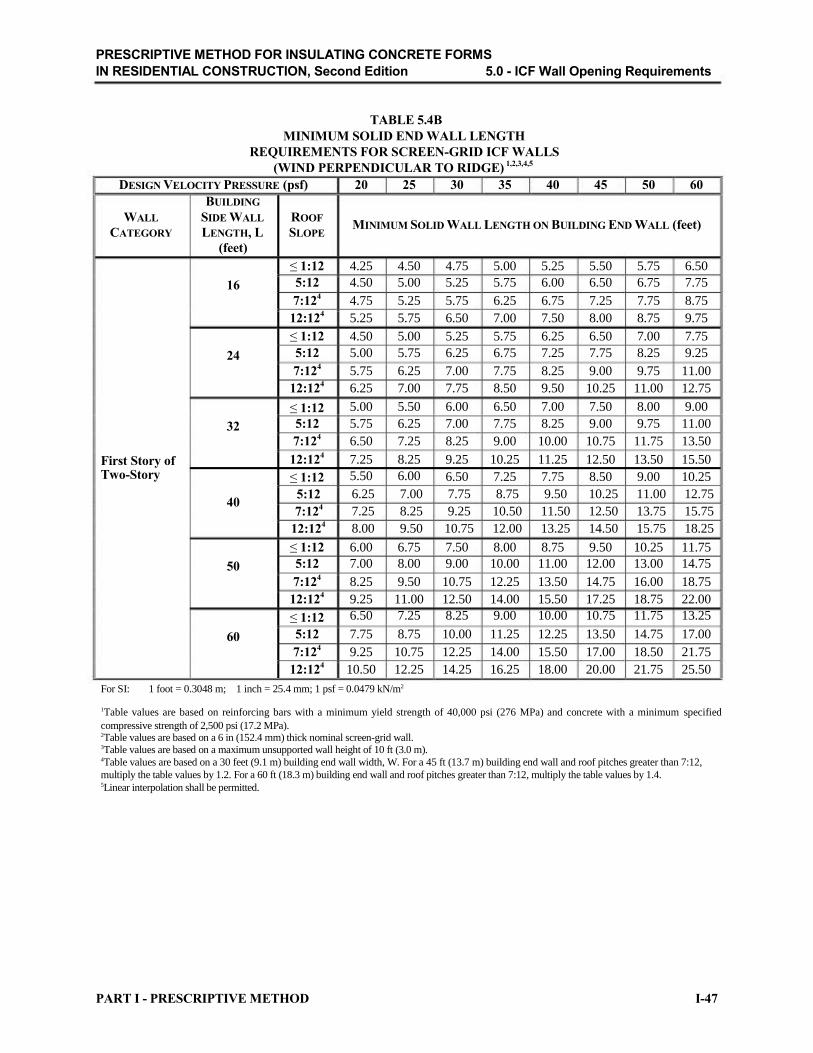
PRESCRIPTIVE METHOD FOR INSULATING CONCRETE FORMS
IN RESIDENTIAL CONSTRUCTION, Second Edition 5.0 - ICF Wall Opening Requirements
TABLE 5.4B
MINIMUM SOLID END WALL LENGTH
REQUIREMENTS FOR SCREEN-GRID ICF WALLS
(WIND PERPENDICULAR TO RIDGE) 1,2,3,4,5
DESIGN VELOCITY PRESSURE (psf) 20 25 30 35 40 45 50 60
BUILDING
WALL SIDE WALL ROOF
CATEGORY LENGTH, L SLOPE
(feet)
MINIMUM SOLID WALL LENGTH ON BUILDING END WALL (feet)
≤ 1:12 4.25 4.50 4.75 5.00 5.25 5.50 5.75 6.50
16 5:12 4.50 5.00 5.25 5.75 6.00 6.50 6.75 7.75
7:124
4.75 5.25 5.75 6.25 6.75 7.25 7.75 8.75
12:124
5.25 5.75 6.50 7.00 7.50 8.00 8.75 9.75
≤ 1:12 4.50 5.00 5.25 5.75 6.25 6.50 7.00 7.75
24 5:12 5.00 5.75 6.25 6.75 7.25 7.75 8.25 9.25
7:124
5.75 6.25 7.00 7.75 8.25 9.00 9.75 11.00
12:124
6.25 7.00 7.75 8.50 9.50 10.25 11.00 12.75
≤ 1:12 5.00 5.50 6.00 6.50 7.00 7.50 8.00 9.00
32 5:12 5.75 6.25 7.00 7.75 8.25 9.00 9.75 11.00
7:124
6.50 7.25 8.25 9.00 10.00 10.75 11.75 13.50
First Story of 12:124
7.25 8.25 9.25 10.25 11.25 12.50 13.50 15.50
Two-Story ≤ 1:12 5.50 6.00 6.50 7.25 7.75 8.50 9.00 10.25
40 5:12
7:124
12:124
6.25 7.00 7.75
7.25 8.25 9.25
8.00 9.50 10.75
8.75 9.50 10.25 11.00 12.75
10.50 11.50 12.50 13.75 15.75
12.00 13.25 14.50 15.75 18.25
≤ 1:12 6.00 6.75 7.50 8.00 8.75 9.50 10.25 11.75
50 5:12 7.00 8.00 9.00 10.00 11.00 12.00 13.00 14.75
7:124
8.25 9.50 10.75 12.25 13.50 14.75 16.00 18.75
12:124
9.25 11.00 12.50 14.00 15.50 17.25 18.75 22.00
≤ 1:12 6.50 7.25 8.25 9.00 10.00 10.75 11.75 13.25
60 5:12 7.75 8.75 10.00 11.25 12.25 13.50 14.75 17.00
7:124
9.25 10.75 12.25 14.00 15.50 17.00 18.50 21.75
12:124
10.50 12.25 14.25 16.25 18.00 20.00 21.75 25.50
For SI: 1 foot = 0.3048 m; 1 inch = 25.4 mm; 1 psf = 0.0479 kN/m2
1Table values are based on reinforcing bars with a minimum yield strength of 40,000 psi (276 MPa) and concrete with a minimum specified
compressive strength of 2,500 psi (17.2 MPa). 2Table values are based on a 6 in (152.4 mm) thick nominal screen-grid wall. 3Table values are based on a maximum unsupported wall height of 10 ft (3.0 m). 4Table values are based on a 30 feet (9.1 m) building end wall width, W. For a 45 ft (13.7 m) building end wall and roof pitches greater than 7:12,
multiply the table values by 1.2. For a 60 ft (18.3 m) building end wall and roof pitches greater than 7:12, multiply the table values by 1.4. 5Linear interpolation shall be permitted.
PART I - PRESCRIPTIVE METHOD I-47

PRESCRIPTIVE METHOD FOR INSULATING CONCRETE FORMS
IN RESIDENTIAL CONSTRUCTION, Second Edition 5.0 - ICF Wall Opening Requirements
TABLE 5.4C
MINIMUM SOLID SIDE WALL LENGTH
REQUIREMENTS FOR SCREEN-GRID ICF WALLS
(WIND PARALLEL TO RIDGE) 1,2,3,4,5
DESIGN VELOCITY PRESSURE (psf) 20 25 30 35 40 45 50 60
WALL
CATEGORY
BUILDING END
WALL WIDTH, W MINIMUM SOLID WALL LENGTH ON BUILDING SIDE WALL (feet)
(feet)
16 4.00 4.00 4.00 4.25 4.25 4.50 4.75 5.00
One-Story or
Top Story of
Two-Story
24 4.00 4.25
32 4.50 5.00
40 5.25 6.00
50 6.50 7.25
4.50 5.00 5.25 5.50 5.75 6.25
5.50 5.75 6.25 6.75 7.00 8.00
6.50 7.00 7.75 8.25 8.75 10.00
8.00 9.00 9.75 10.75 11.50 13.25
60 7.75 8.75 10.00 11.25 12.25 13.50 14.50 17.00
16 4.50 4.75 5.25 5.50 5.75 6.25 6.50 7.25
24 5.00 5.75 6.25 6.75 7.25 7.75 8.25 9.50
First Story of 32 6.00 6.75 7.50 8.25 9.00 9.75 10.50 12.00
Two-Story 40 7.00 8.00 9.00 10.00 11.00 12.00 13.00 15.00
50 8.50 9.75 11.25 12.50 14.00 15.25 16.75 19.50
60 10.25 12.00 13.75 15.50 17.25 19.00 21.00 24.50
For SI: 1 foot = 0.3048 m; 1 inch = 25.4 mm; 1 psf = 0.0479 kN/m2
1Table values are based on reinforcing bars with a minimum yield strength of 40,000 psi (276 MPa) and concrete with a minimum specified compressive strength of 2,500 psi (17.2 MPa). 2Table values are based on a 6 in (152.4 mm) thick nominal screen-grid wall. 3Table values are based on a maximum unsupported wall height of 10 ft (3.0 m). 4Table values are based on a maximum 12:12 roof pitch. 5Linear interpolation shall be permitted.
I-48 PART I - PRESCRIPTIVE METHOD

PRESCRIPTIVE METHOD FOR INSULATING CONCRETE FORMS
IN RESIDENTIAL CONSTRUCTION, Second Edition 5.0 - ICF Wall Opening Requirements
TABLE 5.5
MINIMUM PERCENTAGE OF SOLID WALL LENGTH ALONG EXTERIOR WALL LINES FOR SEISMIC DESIGN CATEGORY C AND D
1,2
ICF WALL TYPE AND
MINIMUM WALL THICKNESS
(inches)
Seismic Design Category C3
Seismic Design Category D14
Seismic Design Category D24
MINIMUM SOLID WALL LENGTH (percent)
ONE-STORY OR WALL SUPPORTING WALL SUPPORTING
TOP STORY OF LIGHT FRAME SECOND ICF SECOND STORY
TWO-STORY STORY AND ROOF AND ROOF
20 percent 25 percent 35 percent
25 percent 30 percent 40 percent
30 percent 35 percent 45 percent
For SI: 1 inch = 25.4 mm; 1 mph = 1.6093 km/hr
1Base percentages are applicable for maximum unsupported wall height of 10-feet (3.0-m), light-frame gable construction, all ICF wall types in
Seismic Design Category C, and all ICF wall types with a nominal thickness greater than 5.5 inches (140 mm) for Seismic Design
Category D1 and D2. 2For all walls, the minimum required length of solid walls shall be based on the table percent value multiplied by the minimum dimension of a rectangle inscribing the overall building plan. 3Walls shall be reinforced with minimum No. 5 rebar (grade 40 or 60) spaced a maximum of 24 inches (609.6 mm) on center each way or
No. 4 rebar (Grade 40 or 60) spaced at a maximum of 16 inches (406.4 mm) on center each way. 4Walls shall be constructed with a minimum concrete compressive strength of 3,000 psi (20.7 MPa) and reinforced with minimum #5 rebar (Grade 60, ASTM A706) spaced a maximum of 18 inches (457.2 mm) on center each way or No. 4 rebar (Grade 60 ASTM A706) spaced at a maximum of 12 inches (304.8 mm) on center each way.
TABLE 5.6
MINIMUM WALL OPENING REINFORCEMENT REQUIREMENTS IN ICF WALLS
WALL TYPE AND MINIMUM
OPENING WIDTH, L HORIZONTAL OPENING
feet (m) REINFORCEMENT
Flat, Waffle-, and None Required
Screen-Grid:
L < 2 (0.61)
Provide lintels in accordance with Section
5.3. Top and bottom lintel reinforcement
shall extend a minimum of 24 inches (610
mm) beyond the limits of the opening.
Flat, Waffle-, and
Screen-Grid: Provide one No. 4 bar within of 12 inches
L ≥ 2 (0.61) (305 mm) from the bottom of the opening. Each No. 4 bar shall extend 24 inches (610 mm) beyond the limits of the opening.
PART I - PRESCRIPTIVE METHOD
MINIMUM
VERTICAL OPENING
REINFORCEMENT
None Required
In locations with wind speeds less than or
equal to 110 mph (177 km/hr) or in Seismic
Design Categories A and B, provide one
No. 4 bar for the full height of the wall
story within 12 inches (305 mm) of each
side of the opening.
In locations with wind speeds greater than
110 mph (177 km/hr) or in Seismic Design
Categories C, D1 and D2, provide two No. 4
bars or one No. 5 bar for the full height of
the wall story within 12 inches (305 mm) of
each side of the opening.
I-49
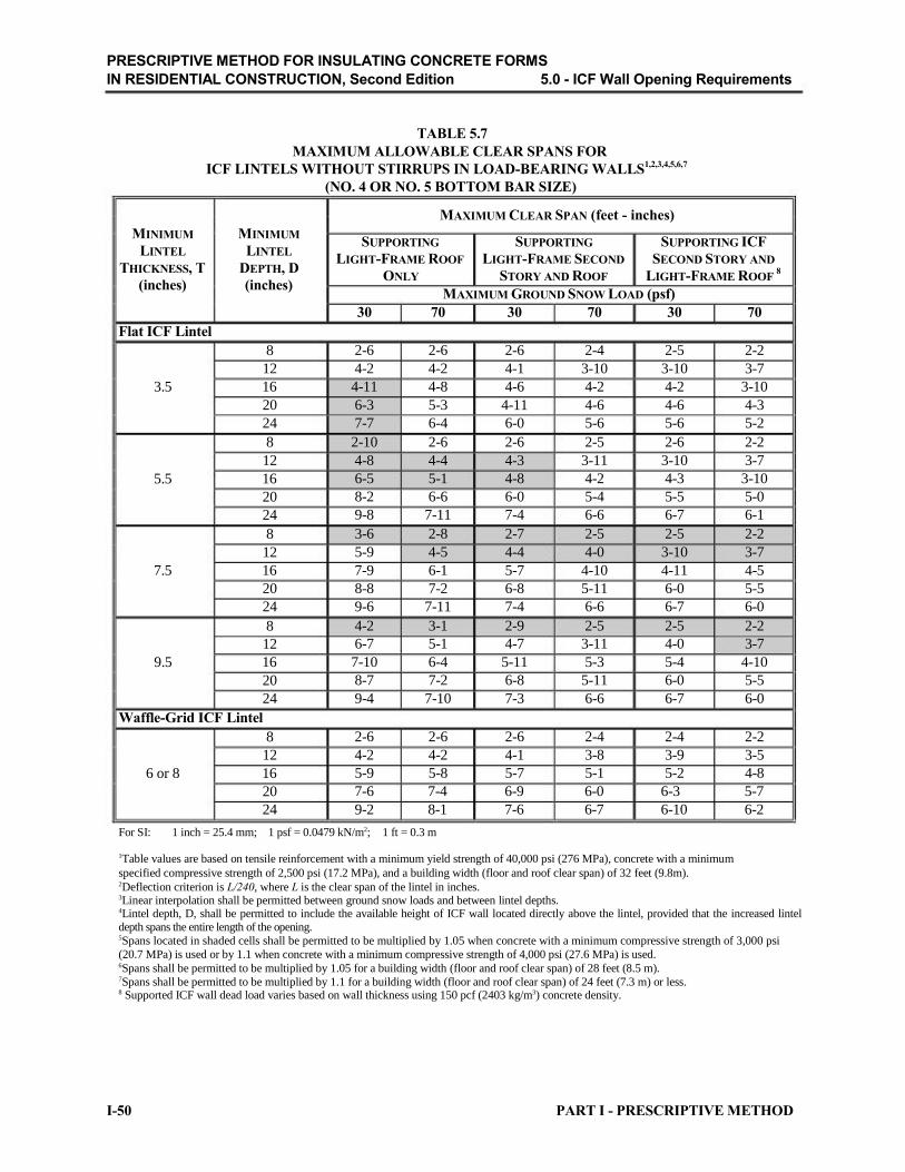
PRESCRIPTIVE METHOD FOR INSULATING CONCRETE FORMS
IN RESIDENTIAL CONSTRUCTION, Second Edition 5.0 - ICF Wall Opening Requirements
TABLE 5.7
MAXIMUM ALLOWABLE CLEAR SPANS FOR
ICF LINTELS WITHOUT STIRRUPS IN LOAD-BEARING WALLS1,2,3,4,5,6,7
(NO. 4 OR NO. 5 BOTTOM BAR SIZE)
MAXIMUM CLEAR SPAN (feet - inches)
MINIMUM MINIMUM
LINTEL LINTEL
THICKNESS, T DEPTH, D
(inches) (inches)
Flat ICF Lintel
8
12
3.5 16
20
24
8
12
5.5 16
20
24
8
12
7.5 16
20
24
8
12
9.5 16
20
24
Waffle-Grid ICF Lintel
8
12
6 or 8 16
20
24
SUPPORTING SUPPORTING SUPPORTING ICF
LIGHT-FRAME ROOF LIGHT-FRAME SECOND SECOND STORY AND
ONLY STORY AND ROOF LIGHT-FRAME ROOF 8
MAXIMUM GROUND SNOW LOAD (psf)
30 70 30 70 30 70
2-6 2-6 2-6 2-4 2-5 2-2
4-2 4-2 4-1 3-10 3-10 3-7
4-11 4-8 4-6 4-2 4-2 3-10
6-3 5-3 4-11 4-6 4-6 4-3
7-7 6-4 6-0 5-6 5-6 5-2
2-10 2-6 2-6 2-5 2-6 2-2
4-8 4-4 4-3 3-11 3-10 3-7
6-5 5-1 4-8 4-2 4-3 3-10
8-2 6-6 6-0 5-4 5-5 5-0
9-8 7-11 7-4 6-6 6-7 6-1
3-6 2-8 2-7 2-5 2-5 2-2
5-9 4-5 4-4 4-0 3-10 3-7
7-9 6-1 5-7 4-10 4-11 4-5
8-8 7-2 6-8 5-11 6-0 5-5
9-6 7-11 7-4 6-6 6-7 6-0
4-2 3-1 2-9 2-5 2-5 2-2
6-7 5-1 4-7 3-11 4-0 3-7
7-10 6-4 5-11 5-3 5-4 4-10
8-7 7-2 6-8 5-11 6-0 5-5
9-4 7-10 7-3 6-6 6-7 6-0
2-6 2-6 2-6 2-4 2-4 2-2
4-2 4-2 4-1 3-8 3-9 3-5
5-9 5-8 5-7 5-1 5-2 4-8
7-6 7-4 6-9 6-0 6-3 5-7
9-2 8-1 7-6 6-7 6-10 6-2
For SI: 1 inch = 25.4 mm; 1 psf = 0.0479 kN/m2; 1 ft = 0.3 m
1Table values are based on tensile reinforcement with a minimum yield strength of 40,000 psi (276 MPa), concrete with a minimum
specified compressive strength of 2,500 psi (17.2 MPa), and a building width (floor and roof clear span) of 32 feet (9.8m). 2Deflection criterion is L/240, where L is the clear span of the lintel in inches. 3Linear interpolation shall be permitted between ground snow loads and between lintel depths. 4Lintel depth, D, shall be permitted to include the available height of ICF wall located directly above the lintel, provided that the increased lintel depth spans the entire length of the opening. 5Spans located in shaded cells shall be permitted to be multiplied by 1.05 when concrete with a minimum compressive strength of 3,000 psi
(20.7 MPa) is used or by 1.1 when concrete with a minimum compressive strength of 4,000 psi (27.6 MPa) is used. 6Spans shall be permitted to be multiplied by 1.05 for a building width (floor and roof clear span) of 28 feet (8.5 m). 7Spans shall be permitted to be multiplied by 1.1 for a building width (floor and roof clear span) of 24 feet (7.3 m) or less. 8 Supported ICF wall dead load varies based on wall thickness using 150 pcf (2403 kg/m3) concrete density.
I-50 PART I - PRESCRIPTIVE METHOD

PRESCRIPTIVE METHOD FOR INSULATING CONCRETE FORMS
IN RESIDENTIAL CONSTRUCTION, Second Edition 5.0 - ICF Wall Opening Requirements
TABLE 5.8A
MAXIMUM ALLOWABLE CLEAR SPANS FOR
FLAT ICF LINTELS WITH STIRRUPS IN LOAD-BEARING WALLS1,2,3,4,5,6,7
(NO. 4 BOTTOM BAR SIZE)
MAXIMUM CLEAR SPAN (feet - inches)
MINIMUM MINIMUM
LINTEL LINTEL
THICKNESS, T DEPTH, D
(inches) (inches)
8
12
3.5 16
20
24
8
12
5.5 16
20
24
8
12
7.5 16
20
24
8
12
9.5 16
20
24
SUPPORTING SUPPORTING SUPPORTING ICF
LIGHT-FRAME ROOF LIGHT-FRAME SECOND SECOND STORY AND
ONLY STORY AND ROOF LIGHT-FRAME ROOF 8
MAXIMUM GROUND SNOW LOAD (psf)
30 70 30 70 30 70
4-9 4-2 3-10 3-4 3-5 3-1
6-8 5-5 5-0 4-5 4-6 4-0
7-11 6-5 6-0 5-3 5-4 4-10
8-11 7-4 6-9 6-0 6-1 5-6
9-10 8-1 7-6 6-7 6-9 6-1
5-2 4-2 3-10 3-5 3-5 3-1
6-8 5-5 5-0 4-5 4-6 4-1
7-10 6-5 6-0 5-3 5-4 4-10
8-10 7-3 6-9 6-0 6-1 5-6
9-8 8-0 7-5 6-7 6-8 6-0
5-2 4-2 3-11 3-5 3-6 3-2
6-7 5-5 5-0 4-5 4-6 4-1
7-9 6-5 5-11 5-3 5-4 4-10
8-8 7-2 6-8 5-11 6-0 5-5
9-6 7-11 7-4 6-6 6-7 6-0
5-2 4-2 3-11 3-5 3-6 3-2
6-7 5-5 5-0 4-5 4-6 4-1
7-8 6-4 5-11 5-3 5-4 4-10
8-7 7-2 6-8 5-11 6-0 5-5
9-4 7-10 7-3 6-6 6-7 6-0
For SI: 1 inch = 25.4 mm; 1 psf = 0.0479 kN/m2; 1 ft = 0.3 m 1Table values are based on concrete with a minimum specified compressive strength of 2,500 psi (17.2 MPa), reinforcing steel with a minimum yield strength of 40,000 psi (276 MPa), and a building width (floor and roof clear span) of 32 feet (9.8m). 2Deflection criterion is L/240, where L is the clear span of the lintel in inches. 3Linear interpolation is permitted between ground snow loads and between lintel depths. 4Lintel depth, D, is permitted to include the available height of ICF wall located directly above the lintel, provided that the increased lintel depth spans the entire length of the lintel. 5Spans located in shaded cells shall be permitted to be multiplied by 1.2 when reinforcing steel with a minimum yield strength of 60,000 psi (414 MPa) is used. 6Spans shall be permitted to be multiplied by 1.05 for a building width (floor and roof clear span) of 28 feet (8.5 m). 7Spans shall be permitted to be multiplied by 1.1 for a building width (floor and roof clear span) of 24 feet or less (7.3 m). 8Supported ICF wall dead load is 69 psf (3.3 kPa).
PART I - PRESCRIPTIVE METHOD I-51

PRESCRIPTIVE METHOD FOR INSULATING CONCRETE FORMS
IN RESIDENTIAL CONSTRUCTION, Second Edition 5.0 - ICF Wall Opening Requirements
TABLE 5.8B
MAXIMUM ALLOWABLE CLEAR SPANS FOR
FLAT ICF LINTELS WITH STIRRUPS IN LOAD-BEARING WALLS1,2,3,4,5,6,7
(NO. 5 BOTTOM BAR SIZE)
MAXIMUM CLEAR SPAN (feet - inches)
MINIMUM MINIMUM
LINTEL LINTEL
THICKNESS, T DEPTH, D
(inches) (inches)
8
12
3.5 16
20
24
8
12
5.5 16
20
24
8
12
7.5 16
20
24
8
12
9.5 16
20
24
SUPPORTING SUPPORTING SUPPORTING ICF
LIGHT-FRAME ROOF LIGHT-FRAME SECOND SECOND STORY AND
ONLY STORY AND ROOF LIGHT-FRAME ROOF 8
MAXIMUM GROUND SNOW LOAD (psf)
30 70 30 70 30 70
4-9 4-2 3-11 3-7 3-7 3-5
7-2 6-3 5-11 5-5 5-5 5-0
9-6 8-0 7-4 6-6 6-7 5-11
11-1 9-1 8-4 7-5 7-6 6-9
12-2 10-0 9-3 8-2 8-4 7-6
5-6 4-10 4-7 4-2 4-2 3-10
8-3 6-9 6-3 5-6 5-7 5-0
9-9 8-0 7-5 6-6 6-7 6-0
10-11 9-0 8-4 7-5 7-6 6-9
12-0 9-11 9-3 8-2 8-3 7-6
6-1 5-2 4-9 4-3 4-3 3-10
8-2 6-9 6-3 5-6 5-7 5-0
9-7 7-11 7-4 6-6 6-7 6-0
10-10 8-11 8-4 7-4 7-6 6-9
11-10 9-10 9-2 8-1 8-3 7-5
6-4 5-2 4-10 4-3 4-4 3-11
8-2 6-8 6-2 5-6 5-7 5-0
9-6 7-11 7-4 6-6 6-7 5-11
10-8 8-10 8-3 7-4 7-5 6-9
11-7 9-9 9-0 8-1 8-2 7-5
For SI: 1 inch = 25.4 mm; 1 psf = 0.0479 kN/m2; 1 ft = 0.3 m
1Table values are based on concrete with a minimum specified compressive strength of 2,500 psi (17.2 MPa), reinforcing steel with a
minimum yield strength of 40,000 psi (276 MPa), and a building width (floor and roof clear span) of 32 feet (9.8m). 2Deflection criterion is L/240, where L is the clear span of the lintel in inches. 3Linear interpolation is permitted between ground snow loads and between lintel depths. 4Lintel depth, D, is permitted to include the available height of ICF wall located directly above the lintel, provided that the increased lintel depth spans the entire length of the lintel. 5Spans located in shaded cells shall be permitted to be multiplied by 1.2 when reinforcing steel with a minimum yield strength of 60,000 psi (414 MPa) is used. 6Spans shall be permitted to be multiplied by 1.05 for a building width (floor and roof clear span) of 28 feet (8.5 m). 7Spans shall be permitted to be multiplied by 1.1 for a building width (floor and roof clear span) of 24 feet (7.3 m) or less. 8Supported ICF wall dead load is 69 psf (3.3 kPa).
I-52 PART I - PRESCRIPTIVE METHOD

PRESCRIPTIVE METHOD FOR INSULATING CONCRETE FORMS
IN RESIDENTIAL CONSTRUCTION, Second Edition 5.0 - ICF Wall Opening Requirements
TABLE 5.9A
MAXIMUM ALLOWABLE CLEAR SPANS FOR
WAFFLE-GRID ICF LINTELS WITH STIRRUPS IN LOAD-BEARING WALLS1,2,3,4,5,6,7
(NO. 4 BOTTOM BAR SIZE)
MAXIMUM CLEAR SPAN (feet - inches)
MINIMUM MINIMUM
LINTEL LINTEL
THICKNESS, T8
DEPTH, D
(inches) (inches)
8
12
6 16
20
24
8
12
8 16
20
24
SUPPORTING SUPPORTING SUPPORTING ICF
LIGHT-FRAME ROOF LIGHT-FRAME SECOND SECOND STORY AND
ONLY STORY AND ROOF LIGHT-FRAME ROOF 9
MAXIMUM GROUND SNOW LOAD (psf)
30 70 30 70 30 70
5-2 4-2 3-10 3-5 3-6 3-2
6-8 5-5 5-0 4-5 4-7 4-2
7-11 6-6 6-0 5-3 5-6 4-11
8-11 7-4 6-9 6-0 6-3 5-7
9-10 8-1 7-6 6-7 6-10 6-2
5-2 4-3 3-11 3-5 3-7 3-2
6-8 5-5 5-1 4-5 4-8 4-2
7-10 6-5 6-0 5-3 5-6 4-11
8-10 7-3 6-9 6-0 6-2 5-7
9-8 8-0 7-5 6-7 6-10 6-2
For SI: 1 inch = 25.4 mm; 1 psf = 0.0479 kN/m2; 1 ft = 0.3 m
1Table values are based on concrete with a minimum specified compressive strength of 2,500 psi (17.2 MPa), reinforcing steel with a
minimum yield strength of 40,000 psi (276 MPa), and a building width (floor and roof clear span) of 32 feet (9.8m). 2Deflection criterion is L/240, where L is the clear span of the lintel in inches. 3Linear interpolation is permitted between ground snow loads and between lintel depths. 4Lintel depth, D, is permitted to include the available height of ICF wall located directly above the lintel, provided that the increased lintel depth spans the entire length of the lintel. 5Spans located in shaded cells shall be permitted to be multiplied by 1.2 when reinforcing steel with a minimum yield strength of 60,000 psi (414 MPa) is used. 6Spans shall be permitted to be multiplied by 1.05 for a building width (floor and roof clear span) of 28 feet (8.5 m). 7Spans shall be permitted to be multiplied by 1.1 for a building width (floor and roof clear span) of 24 feet (7.3 m) or less. 8Lintel thickness corresponds to the nominal waffle-grid ICF wall thickness with a minimum web thickness of 2 inches (51 mm). For actual
wall thickness, refer to section 2.0. 9Supported ICF wall dead load is 55 psf (2.6 kPa).
PART I - PRESCRIPTIVE METHOD I-53

PRESCRIPTIVE METHOD FOR INSULATING CONCRETE FORMS
IN RESIDENTIAL CONSTRUCTION, Second Edition 5.0 - ICF Wall Opening Requirements
TABLE 5.9B
MAXIMUM ALLOWABLE CLEAR SPANS FOR
WAFFLE-GRID ICF LINTELS WITH STIRRUPS IN LOAD-BEARING WALLS1,2,3,4,5,6,7
(NO. 5 BOTTOM BAR SIZE)
MAXIMUM CLEAR SPAN (feet - inches)
MINIMUM MINIMUM
LINTEL LINTEL
THICKNESS, T8
DEPTH, D
(inches) (inches)
8
12
6 16
20
24
SUPPORTING SUPPORTING SUPPORTING ICF
LIGHT-FRAME ROOF LIGHT-FRAME SECOND SECOND STORY AND
ONLY STORY AND ROOF LIGHT-FRAME ROOF 9
MAXIMUM GROUND SNOW LOAD (psf)
30 70 30 70 30 70
5-4 4-8 4-5 4-1 4-5 3-10
8-0 6-9 6-3 5-6 6-3 5-1
9-9 8-0 7-5 6-6 7-5 6-1
11-0 9-1 8-5 7-5 8-5 6-11
12-2 10-0 9-3 8-2 9-3 7-8
8 6-0 5-2 4-9 4-3 4-9 3-11
12 8-3 6-9 6-3 5-6 6-3 5-2
8 16 9-9 8-0 7-5 6-6 7-5 6-1
20 10-11 9-0 8-4 7-5 8-4 6-11
24 12-0 9-11 9-2 8-2 9-2 7-8
For SI: 1 inch = 25.4 mm; 1 psf = 0.0479 kN/m2; 1 ft = 0.3 m
1Table values are based on concrete with a minimum specified compressive strength of 2,500 psi (17.2 MPa), reinforcing steel with a
minimum yield strength of 40,000 psi (276 MPa), and a building width (floor and roof clear span) of 32 feet (9.8m). 2Deflection criterion is L/240, where L is the clear span of the lintel in inches. 3Linear interpolation is permitted between ground snow loads and between lintel depths. 4Lintel depth, D, is permitted to include the available height of ICF wall located directly above the lintel, provided that the increased lintel depth spans the entire length of the lintel. 5Spans located in shaded cells shall be permitted to be multiplied by 1.2 when reinforcing steel with a minimum yield strength of 60,000 psi (414 MPa) is used. 6Spans shall be permitted to be multiplied by 1.05 for a building width (floor and roof clear span) of 28 feet (8.5 m). 7Spans shall be permitted to be multiplied by 1.1 for a building width (floor and roof clear span) of 24 feet (7.3 m) or less. 8Lintel thickness corresponds to the nominal waffle-grid ICF wall thickness with a minimum web thickness of 2 inches (51 mm). For actual
wall thickness, refer to section 2.0. 9Supported ICF wall dead load is 55 psf (2.6 kPa).
I-54 PART I - PRESCRIPTIVE METHOD

PRESCRIPTIVE METHOD FOR INSULATING CONCRETE FORMS
IN RESIDENTIAL CONSTRUCTION, Second Edition 5.0 - ICF Wall Opening Requirements
TABLE 5.10A
MAXIMUM ALLOWABLE CLEAR SPANS FOR
SCREEN-GRID ICF LINTELS IN LOAD-BEARING WALLS1,2,3,4,5,6,7,8
(NO. 4 BOTTOM BAR SIZE)
MAXIMUM CLEAR SPAN (feet - inches)
MINIMUM MINIMUM
LINTEL LINTEL
THICKNESS, T9
DEPTH, D
(inches) (inches)
6 12
24
SUPPORTING SUPPORTING SUPPORTING ICF
LIGHT-FRAME ROOF LIGHT-FRAME SECOND SECOND STORY AND
ONLY STORY AND ROOF LIGHT-FRAME ROOF 10
MAXIMUM GROUND SNOW LOAD (psf)
30 70 30 70 30 70
3-7 2-10 2-5 2-0 2-0 D/R
9-10 8-1 7-6 6-7 6-11 6-2
For SI: 1 inch = 25.4 mm; 1 psf = 0.0479 kN/m2; 1 ft = 0.3 m 1Table values are based on concrete with a minimum specified compressive strength of 2,500 psi (17.2 MPa), reinforcing steel with a minimum yield strength of 40,000 psi (276 MPa), and a building width (floor and roof clear span) of 32 feet (9.8m); D/R indicates design required. 2Stirups are not required for 12 in (304.8 mm) deep screen-grid lintels. Stirrups shall be required at a maximum spacing of 12 inches (304.8 mm) on center for 24 in (609.6 mm) deep screen-grid lintels. 3Deflection criterion is L/240, where L is the clear span of the lintel in inches. 4Linear interpolation is permitted between ground snow loads and between lintel depths. 5Spans located in shaded cells shall be permitted to be multiplied by 1.2 when reinforcing steel with a minimum yield strength of 60,000 psi (414 MPa) is used. 6Spans shall be permitted to be multiplied by 1.05 for a building width (floor and roof clear span) of 28 feet (8.5 m). 7Spans shall be permitted to be multiplied by 1.10 for a building width (floor and roof clear span) of 24 feet (7.3 m). 8Flat ICF lintels may be used in lieu of screen-grid lintels. 9Lintel thickness corresponds to the nominal screen-grid ICF wall thickness. For actual wall thickness, refer to section 2.0. 10Supported ICF wall dead load is 53 psf (2.5 kPa).
TABLE 5.10B MAXIMUM ALLOWABLE CLEAR SPANS FOR
SCREEN-GRID ICF LINTELS IN LOAD-BEARING WALLS1,2,3,4,5,6,7,8
(NO. 5 BOTTOM BAR SIZE)
MAXIMUM CLEAR SPAN (feet - inches)
MINIMUM MINIMUM
LINTEL LINTEL
THICKNESS, T9
DEPTH, D
(inches) (inches)
6 12
24
SUPPORTING SUPPORTING SUPPORTING ICF
LIGHT-FRAME ROOF LIGHT-FRAME SECOND SECOND STORY AND
ONLY STORY AND ROOF LIGHT-FRAME ROOF 10
MAXIMUM GROUND SNOW LOAD (psf)
30 70 30 70 30 70
3-7 2-10 2-5 1-10 2-0 D/R
12-2 10-0 9-3 8-3 8-7 7-8
For SI: 1 inch = 25.4 mm; 1 psf = 0.0479 kN/m2; 1 ft = 0.3 m
1Table values are based on concrete with a minimum specified compressive strength of 2,500 psi (17.2 MPa), reinforcing steel with a minimum
yield strength of 40,000 psi (276 MPa), and a building width (floor and roof clear span) of 32 feet (9.8m); D/R indicates design required. 2Stirups are not required for 12 in (304.8 mm) deep screen-grid lintels. Stirrups shall be required at a maximum spacing of 12 inches
(304.8 mm) on center for 24 in (609.6 mm) deep screen-grid lintels. 3Deflection criterion is L/240, where L is the clear span of the lintel in inches. 4Linear interpolation is permitted between ground snow loads and between lintel depths. Lintel depth, D, is permitted to include the available
height of any ICF wall located directly above the lintel, provided that the increased lintel depth spans the entire length of the lintel. 5Spans located in shaded cells shall be permitted to be multiplied by 1.2 when reinforcing steel with a minimum yield strength of 60,000 psi
(414 MPa) is used. 6Spans shall be permitted to be multiplied by 1.05 for a building width (floor and roof clear span) of 28 feet (8.5 m). 7Spans shall be permitted to be multiplied by 1.10 for a building width (floor and roof clear span) of 24 feet (7.3 m). 8Flat ICF lintel may be used in lieu of screen-grid lintels. 9Lintel thickness corresponds to the nominal screen-grid ICF wall thickness. For actual wall thickness, refer to section 2.0. 10Supported ICF wall dead load is 53 psf (2.5 kPa).
PART I - PRESCRIPTIVE METHOD I-55

PRESCRIPTIVE METHOD FOR INSULATING CONCRETE FORMS
IN RESIDENTIAL CONSTRUCTION, Second Edition 5.0 - ICF Wall Opening Requirements
TABLE 5.11
MINIMUM BOTTOM BAR ICF LINTEL REINFORCEMENT FOR LARGE CLEAR SPANS WITH STIRRUPS IN LOAD-BEARING WALLS
1,2,3,4,5
MINIMUM BOTTOM LINTEL REINFORCEMENT (quantity - size)
MINIMUM MINIMUM
LINTEL LINTEL
THICKNESS, T6
DEPTH, D
(inches) (inches)
SUPPORTING SUPPORTING SUPPORTING ICF
LIGHT-FRAME ROOF LIGHT-FRAME SECOND SECOND STORY AND
ONLY STORY AND ROOF LIGHT-FRAME ROOF 7
MAXIMUM GROUND SNOW LOAD (psf)
30 70 30 70 30 70
Flat ICF Lintel, 12 feet - 3 inches Maximum Clear Span
3.5 24 1-#5 D/R D/R D/R D/R D/R
5.5 20 1-#6; 2-#4 2-#5 D/R D/R D/R D/R
24 1-#5 2-#5 2-#5 2-#6 2-#6 D/R
16 2-#5 D/R D/R D/R D/R D/R
7.5 20 1-#6; 2-#4 2-#5 2-#6 D/R D/R D/R
24 1-#6; 2-#4 2-#5 2-#5 2-#6 2-#6 2-#6
9.5 16 2-#5 D/R D/R D/R D/R D/R
20 1-#6; 2-#4 2-#5 2-#6 2-#6 2-#6 2-#6
24 1-#6; 2-#4 2-#5 2-#5 2-#6 2-#6 2-#6
Flat ICF Lintel, 16 feet - 3 inches Maximum Clear Span
5.5 24 2-#5 D/R D/R D/R D/R D/R
7.5 24 2-#5 D/R D/R D/R D/R D/R
9.5 24 2-#5 2-#6 2-#6 D/R D/R D/R
Waffle-Grid ICF Lintel, 12 feet - 3 inches Maximum Clear Span
6 20 1-#6; 2-#4 D/R D/R D/R D/R D/R
24 1-#5 2-#5 2-#5 2-#6 2-#6 D/R
16 2-#5 D/R D/R D/R D/R D/R
8 20 1-#6; 2-#4 2-#5 2-#6 D/R D/R D/R
24 1-#5 2-#5 2-#5 2-#6 2-#6 2-#6
Screen-Grid ICF Lintel, 12 feet - 3 inches Maximum Clear Span
6 24 1-#5 D/R D/R D/R D/R D/R
For SI: 1 inch = 25.4 mm; 1 psf = 0.0479 kN/m2; 1 ft = 0.3 m
1Table values are based on concrete with a minimum specified compressive strength of 2,500 psi (17.2 MPa), reinforcing steel with a minimum
yield strength of 40,000 psi (276 MPa), and a building width (floor and roof clear span) of 32 feet (9.8m). 2D/R indicates design is required. 3Deflection criterion is L/240, where L is the clear span of the lintel in inches. 4Linear interpolation is permitted between ground snow loads and between lintel depths. Lintel depth, D, is permitted to include the available height of ICF wall located directly above the lintel, provided that the increased lintel depth spans the entire length of the lintel. 5 The required reinforcement(s) in the shaded cells shall be permitted to be reduced to the next smallest bar diameter when reinforcing steel with a minimum yield strength of 60,000 psi (414 MPa) is used. 6Actual thickness is shown for flat lintels while nominal thickness is given for waffle-grid and screen-grid lintels. Refer to Section 2.0 for actual wall thickness of waffle-grid and screen-grid ICF construction. 7Supported ICF wall dead load varies based on wall thickness using 150 pcf (2403 kg/m3) concrete density.
I-56 PART I - PRESCRIPTIVE METHOD

PRESCRIPTIVE METHOD FOR INSULATING CONCRETE FORMS
IN RESIDENTIAL CONSTRUCTION, Second Edition 5.0 - ICF Wall Opening Requirements
TABLE 5.12
MIDDLE PORTION OF SPAN, A, WHERE STIRRUPS ARE NOT REQUIRED FOR FLAT ICF LINTELS
1,2,3,4,5,6,7
(NO. 4 or NO. 5 BOTTOM BAR SIZE)
MIDDLE SPAN NOT REQUIRING STIRRUPS (feet - inches)
MINIMUM MINIMUM SUPPORTING SUPPORTING SUPPORTING ICF
LINTEL LINTEL LIGHT-FRAME ROOF LIGHT-FRAME SECOND SECOND STORY AND
THICKNESS, T DEPTH, D ONLY STORY AND ROOF LIGHT-FRAME ROOF
(inches) (inches) MAXIMUM GROUND SNOW LOAD (psf)
30 70 30 70 30 70
8 1-2 0-9 0-8 0-6 0-6 0-5
12 1-11 1-3 1-1 0-10 0-10 0-8
3.5 16 2-7 1-9 1-6 1-2 1-2 1-0
20 3-3 2-3 1-11 1-6 1-6 1-3
24 3-11 2-8 2-4 1-10 1-10 1-6
8 1-10 1-2 1-0 0-9 0-10 0-8
12 3-0 2-0 1-8 1-4 1-4 1-1
5.5 16 4-1 2-9 2-4 1-10 1-11 1-6
20 5-3 3-6 3-0 2-4 2-5 2-0
24 6-3 4-3 3-8 2-10 2-11 2-5
8 2-6 1-8 1-5 1-1 1-1 0-11
12 4-1 2-9 2-4 1-10 1-10 1-6
7.5 16 5-7 3-9 3-3 2-6 2-7 2-1
20 7-1 4-10 4-1 3-3 3-4 2-9
24 8-6 5-9 5-0 3-11 4-0 3-3
8 3-2 2-1 1-9 1-4 1-5 1-2
12 5-2 3-5 2-11 2-3 2-4 1-11
9.5 16 7-1 4-9 4-1 3-2 3-3 2-8
20 9-0 6-1 5-3 4-1 4-2 3-5
24 10-9 7-4 6-4 4-11 5-1 4-2
For SI: 1 inch = 25.4 mm; 1 psf = 0.0479 kN/m2; 1 ft = 0.3 m
1This table is applicable to Tables 5.8A and 5.8B. The values are based on concrete with a minimum specified compressive strength of 2,500
psi (17.2 MPa), reinforcing steel with a minimum yield strength of 40,000 psi (276 MPa), and a building width (floor and roof clear span) of 32 feet (9.8m). 2Deflection criterion is L/240, where L is the clear span of the lintel in inches. 3Linear interpolation is permitted between ground snow loads and between lintel depths. Lintel depth, D, is permitted to include the available height of ICF wall located directly above the lintel, provided that the increased lintel depth spans the entire length of the lintel. 4The middle portion of the span, A, shall be permitted to be multiplied by 1.09 when concrete with a minimum compressive strength of 3,000 psi (20.7 MPa) is used. 5The middle portion of the span, A, shall be permitted to be multiplied by 1.26 when concrete with a minimum compressive strength of
4,000 psi (27.6 MPa) is used. 6The middle portion of the span, A, shall be permitted to be multiplied by 1.1 for a building width (floor and roof clear span) of 28 feet (8.5 m). 7The middle portion of the span, A, shall be permitted to be multiplied by 1.2 for a building width (floor and roof clear span) of 24 feet (7.3 m).
PART I - PRESCRIPTIVE METHOD I-57

PRESCRIPTIVE METHOD FOR INSULATING CONCRETE FORMS
IN RESIDENTIAL CONSTRUCTION, Second Edition 5.0 - ICF Wall Opening Requirements
TABLE 5.13
MIDDLE PORTION OF SPAN, A, WHERE STIRRUPS ARE NOT REQUIRED FOR WAFFLE-GRID ICF LINTELS
1,2,3,4,5,6,7,8
(NO. 4 or NO. 5 BOTTOM BAR SIZE)
MIDDLE SPAN NOT REQUIRING STIRRUP
MINIMUM MINIMUM SUPPORTING SUPPORTING SUPPORTING ICF
LINTEL LINTEL LIGHT-FRAME ROOF LIGHT-FRAME SECOND SECOND STORY AND
THICKNESS, T9
DEPTH, D ONLY STORY AND ROOF LIGHT-FRAME ROOF
(inches) (inches) MAXIMUM GROUND SNOW LOAD (psf)
30 70 30 70 30 70
8 0-10 0-7 0-5 0-4 0-5 0-4
12 1-5 0-11 0-9 0-7 0-8 0-6
6 or 8 16 1-11 1-4 1-1 0-10 0-11 0-9
20 2-6 1-8 1-5 1-1 1-2 0-11
24 3-0 2-0 1-9 1-4 1-5 1-2
For SI: 1 inch = 25.4 mm; 1 psf = 0.0479 kN/m2; 1 ft = 0.3 m
1This table is applicable to Tables 5.9A and B. The values are based on concrete with a minimum specified compressive strength of 2,500
psi (17.2 MPa), reinforcing steel with a minimum yield strength of 40,000 psi (276 MPa), and a building width (floor and roof clear span) of 32 feet (9.8m). 2Deflection criterion is L/240, where L is the clear span of the lintel in inches. 3Linear interpolation is permitted between ground snow loads and between lintel depths. Lintel depth, D, is permitted to include the available
height of any ICF wall located directly above the lintel, provided that the increased lintel depth spans the entire length of the lintel. 4The middle portion of the span, A, shall be permitted to be multiplied by 1.09 when concrete with a minimum compressive strength of
3,000 psi (20.7 MPa) is used. 5The middle portion of the span, A, shall be permitted to be multiplied by 1.26 when concrete with a minimum compressive strength of 4,000 psi (27.6 MPa) is used. 6The middle portion of the span, A, shall be permitted to be multiplied by 1.1 for a building width of (floor and roof clear span) 28 feet
(8.5 m). 7The middle portion of the span, A, shall be permitted to be multiplied by 1.2 for a building width of (floor and roof clear span) 24 feet (7.3 m). 8When required, stirrups shall be placed in each vertical core. 9Lintel thickness corresponds to the nominal waffle-grid ICF wall thickness with a minimum web thickness of 2 inches (51 mm). For actual
wall thickness, refer to Section 2.0.
I-58 PART I - PRESCRIPTIVE METHOD

PRESCRIPTIVE METHOD FOR INSULATING CONCRETE FORMS
IN RESIDENTIAL CONSTRUCTION, Second Edition 5.0 - ICF Wall Opening Requirements
TABLE 5.14
MAXIMUM ALLOWABLE CLEAR SPANS FOR
ICF LINTELS IN GABLE END (NON-LOAD-BEARING) WALLS WITHOUT STIRRUPS1,2
(NO. 4 BOTTOM BAR SIZE)
MINIMUM MINIMUM
LINTEL LINTEL
THICKNESS, T DEPTH, D
(inches) (inches)
Flat ICF Lintel
8
12 3.5 16
20
22
8
12 5.5 16
20
22
8
12 7.5 16
20
22
8
12 9.5 16
20
22
Waffle-Grid ICF Lintel
8
12 6 or 8 16
20
22
Screen-Grid Lintel
6 12
24
MAXIMUM CLEAR SPAN
SUPPORTING SUPPORTING ICF
LIGHT-FRAME GABLE SECOND STORY AND
END WALL GABLE END WALL
(feet-inches) (feet-inches)
11-1 3-1
15-11 5-1
16-3 6-11
16-3 8-8
16-3 10-5
16-3 4-4
16-3 7-0
16-3 9-7
16-3 12-0
16-3 14-3
16-3 5-6
16-3 8-11
16-3 12-2
16-3 15-3
16-3 16-3
16-3 6-9
16-3 10-11
16-3 14-10
16-3 16-3
16-3 16-3
9-1 2-11
13-4 4-10
16-3 6-7
16-3 8-4
16-3 9-11
5-8 4-1
16-3 9-1
For SI: 1 foot = 0.3048 m; 1 inch = 25.4 mm; 1 psf = 47.8804 Pa
1Deflection criterion is L/240, where L is the clear span of the lintel in inches. 2Linear interpolation is permitted between lintel depths.
PART I - PRESCRIPTIVE METHOD I-59

PRESCRIPTIVE METHOD FOR INSULATING CONCRETE FORMS
IN RESIDENTIAL CONSTRUCTION, Second Edition 5.0 - ICF Wall Opening Requirements
Figure 5.1 Variables for Use with Tables 5.2 through 5.4
I-60 PART I - PRESCRIPTIVE METHOD
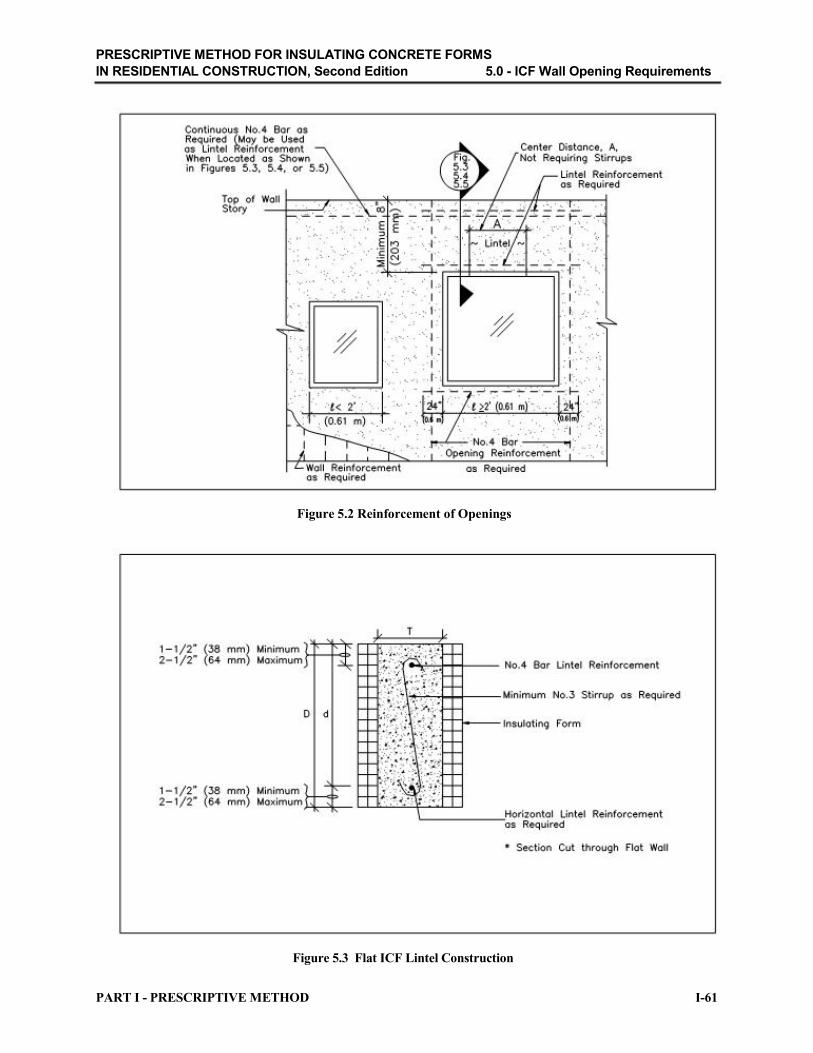
PRESCRIPTIVE METHOD FOR INSULATING CONCRETE FORMS
IN RESIDENTIAL CONSTRUCTION, Second Edition 5.0 - ICF Wall Opening Requirements
Figure 5.2 Reinforcement of Openings
Figure 5.3 Flat ICF Lintel Construction
PART I - PRESCRIPTIVE METHOD I-61

PRESCRIPTIVE METHOD FOR INSULATING CONCRETE FORMS
IN RESIDENTIAL CONSTRUCTION, Second Edition 5.0 - ICF Wall Opening Requirements
Figure 5.4 Waffle-Grid ICF Lintel Construction
I-62 PART I - PRESCRIPTIVE METHOD
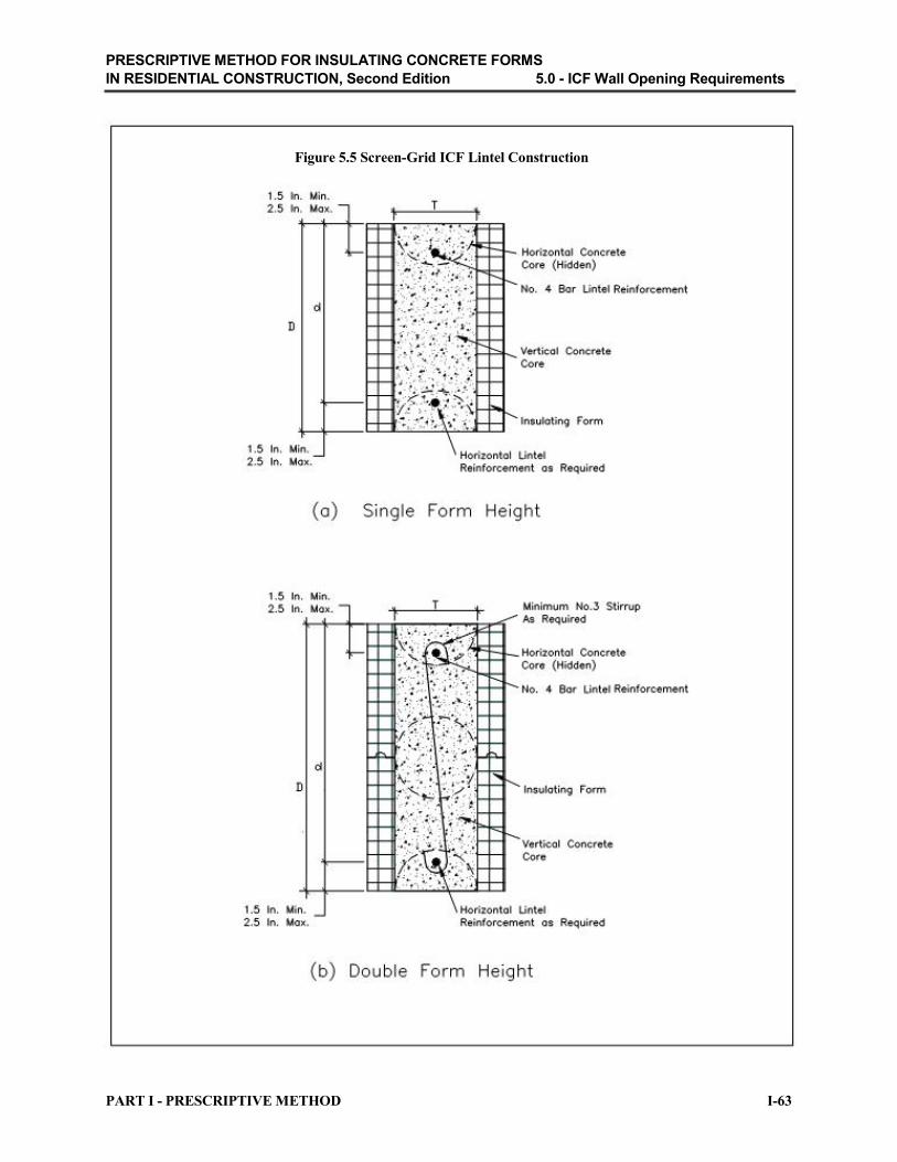
PRESCRIPTIVE METHOD FOR INSULATING CONCRETE FORMS
IN RESIDENTIAL CONSTRUCTION, Second Edition 5.0 - ICF Wall Opening Requirements
Figure 5.5 Screen-Grid ICF Lintel Construction
PART I - PRESCRIPTIVE METHOD I-63

PRESCRIPTIVE METHOD FOR INSULATING CONCRETE FORMS
IN RESIDENTIAL CONSTRUCTION, Second Edition 6.0 - ICF Connection Requirements
6.0 ICF Connection Requirements
All ICF walls shall be connected to footings, floors, and roofs in accordance with this section.
Requirements for installation of brick veneer and other finishes on exterior ICF walls and other
construction details not covered in this section shall comply with the manufacturer’s approved
recommendations, applicable building code requirements, and accepted practice.
6.1 ICF Foundation Wall-to-Footing Connection
No vertical reinforcement (i.e., dowels) across the joint between the foundation wall and the
footing is required when one of the following exists:
• The unbalanced backfill height does not exceed 4 feet (1.2 m).
• The interior floor slab is installed in accordance with Figure 3.3 before backfilling.
• Temporary bracing at the bottom of the foundation wall is erected before backfilling and
remains in place during construction until an interior floor slab is installed in accordance
with Figure 3.3 or the wall is backfilled on both sides (i.e., stem wall).
For foundation walls that do not meet one of the above requirements, vertical reinforcement (i.e.,
dowel) shall be installed across the joint between the foundation wall and the footing at 48 inches
(1.2 m) on center in accordance with Figure 6.1. Vertical reinforcement (i.e., dowels) shall be
provided for all foundation walls for buildings located in regions with 3-second gust design wind
speeds greater than 130 mph (209 km/hr) or located in Seismic Design Categories D1 and D2 at 18 inches (457 mm) on center.
Exception: The foundation wall’s vertical wall reinforcement, at intervals of 4 feet
(1.2 m) on center, shall extend 8 inches (203 mm) into the footing in lieu of using a dowel
as shown in Figure 6.1.
6.2 ICF Wall-to-Floor Connection
6.2.1 Floor on ICF Wall Connection (Top-Bearing Connection)
Floors bearing on ICF walls shall be constructed in accordance with Figure 6.2 or 6.3. The wood sill
plate or floor system shall be anchored to the ICF wall with 1/2-inch- (13-mm-) diameter bolts
placed at a maximum spacing of 6 feet (1.8 m) on center and not more than 12 inches (305 mm) from
joints in the sill plate.
A maximum anchor bolt spacing of 4 feet (1.2 m) on center shall be required when the 3-second
gust design wind speed is 110 mph (177 km/hr) or greater. Anchor bolts shall extend a minimum
of 7 inches (178 mm) into the concrete and a minimum of 2 inches beyond horizontal
reinforcement in the top of the wall. Also, additional anchorage mechanisms shall be installed
connecting each joist to the sill plate. Light-frame construction shall be in accordance with the
applicable building code. I-64 PART I - PRESCRIPTIVE METHOD

PRESCRIPTIVE METHOD FOR INSULATING CONCRETE FORMS
IN RESIDENTIAL CONSTRUCTION, Second Edition 6.0 - ICF Connection Requirements
In Seismic Design Category C, wood sill plates attached to ICF walls shall be anchored with
Grade A 307, 3/8-inch (9.5 mm) diameter anchor bolts embedded a minimum of 7 inches (178
mm) and placed at a maximum spacing of 36 inches (914 mm) on center. In Seismic Design
Category D1, wood sill plates attached to ICF walls shall be anchored with Grade A 307, 3/8
inch (9.5 mm) diameter anchor bolts embedded a minimum of 7 inches (178 mm) and placed at a
maximum spacing of 24 inches (610 mm) on center. In Seismic Design Category D2, wood sill
plates attached to ICF walls shall be anchored with Grade A 307, 3/8-inch (9.5 mm) diameter
anchor bolts embedded a minimum of 7 inches (178 mm) and placed at a maximum spacing of
16 inches (406 mm) on center. The minimum edge distance from the edge of concrete to edge of anchor bolt shall be 2.5 inches (63.5 mm).
In Seismic Design Category C, each floor joist shall be attached to the sill plate with an 18-gauge
angle bracket using 3 - 8d common nails per leg. In Seismic Design Category D1, each floor joist
shall be attached to the sill plate with an 18-gauge angle bracket using 4 - 8d common nails per leg.
In Seismic Design Category D2, each floor joist shall be attached to the sill plate with an 18 gauge
angle bracket using 6 - 8d common nails per leg.
6.2.2 Floor Ledger-ICF Wall Connection (Side-Bearing Connection)
Wood ledger boards shall be anchored to flat ICF walls having a minimum thickness of 5.5
inches (140 mm) thickness and to waffle- or screen-grid ICF walls having a minimum nominal
thickness of 6 inches (152 mm) in accordance with Figure 6.4 or 6.5 and Table 6.1. Wood ledger
boards shall be anchored to flat ICF walls having a minimum thickness of 3.5 inches (89 mm) in
accordance with Figure 6.6 or 6.7 and Table 6.1. Minimum wall thickness shall be 5.5 inches
(140 mm) in Seismic Design Category C, D1, and D2.
Additional anchorage mechanisms shall be installed at a maximum spacing of 6 feet (1.8 m) on
center for Seismic Design Category C and 4 feet (1.2 m) on center for Seismic Design Categories
D1 and D2. The additional anchorage mechanisms shall be attached to the ICF wall reinforcement
and joist, rafters, or blocking in accordance with Figures 6.4 through 6.7. The blocking shall be
attached to floor or roof sheathing in accordance with sheathing panel edge fastener spacing.
Such additional anchorage shall not be accomplished by the use of toe nails or nails subject to
withdrawal nor shall such anchorage mechanisms induce tension stresses perpendicular to grain
in ledgers or nailers. The capacity of such anchors shall result in connections capable of resisting
the design values listed in Table 6.2. The diaphragm sheathing fasteners applied directly to a
ledger shall not be considered effective in providing the additional anchorage required by this
section.
6.2.3 Floor and Roof diaphragm Construction in Seismic Design Categories D1 and D2.
Edge spacing of fasteners in floor and roof sheathing shall be 4 inches (102 mm) on center for
Seismic Design Category D1 and 3 inches (76 mm) on center for Seismic Design Category D2. In
Seismic Design Categories D1 and D2, all sheathing edges shall be attached to framing or
blocking. Minimum sheathing fastener size shall be 0.113 inch (2.8 mm) diameter with a
minimum penetration of 1-3/8 inches (35 mm) into framing members supporting the sheathing.
Minimum wood structural panel thickness shall be 7/16 inch (11 mm) for roof sheathing and
23/32 inch (18 mm) for floor sheathing.
PART I - PRESCRIPTIVE METHOD I-65

PRESCRIPTIVE METHOD FOR INSULATING CONCRETE FORMS
IN RESIDENTIAL CONSTRUCTION, Second Edition 6.0 - ICF Connection Requirements
6.3 ICF Wall-to-Roof Connection
Wood sill plates attaching roof framing to ICF walls shall be anchored to the ICF wall in
accordance with Table 6.3 and Figure 6.8. Anchor bolts shall be located in the middle one-third of
the flat ICF wall thickness or the middle one-third of the vertical core thickness of the waffle-grid
and screen-grid ICF wall system and shall have a minimum embedment of 7 inches (178 mm). Roof
framing attachment to wood sill plates shall be in accordance with the applicable building code.
In conditions where the 3-second gust design wind speed is 110 mph (177 km/hr) or greater, an
approved uplift connector (i.e., strap or bracket) shall be used to attach roof assemblies to wood sill plates in accordance with the applicable building code. Embedment of strap connectors shall be in
accordance with the strap connector manufacturer’s approved recommendations.
In Seismic Design Category C, wood sill plates attaching roof framing to ICF walls shall be anchored with a Grade A 307, 3/8 inch (9.5 mm) diameter anchor bolt embedded a minimum of
7 inches (178 mm) and placed at a maximum spacing of 36 inches (914 mm) on center. Wood
sill plates attaching roof framing to ICF walls shall be anchored with a minimum Grade A 307,
3/8 inch (9.5 mm) diameter anchor bolt embedded a minimum of 7 inches (178 mm) and placed
at maximum spacing of 24 inches (609 mm) on center for Seismic Design Category D1 and a
maximum spacing of 16 inches (406 mm) on center for Seismic Design Category D2. The
minimum edge distance from the edge of concrete to edge of anchor bolt shall be 2.5 inches
(63.5 mm).
In Seismic Design Category C, each rafter or truss shall be attached to the sill plate with an 18
gauge angle bracket using 3 - 8d common nails per leg. For all buildings in Seismic Design
Category D1, each rafter or truss shall be attached to the sill plate with an 18-gauge angle bracket
using 4 - 8d common nails per leg. For all buildings in Seismic Design Category D2, each rafter
or truss shall be attached to the sill plate with an 18-gauge angle bracket using 6 - 8d common
nails per leg.
I-66 PART I - PRESCRIPTIVE METHOD

PRESCRIPTIVE METHOD FOR INSULATING CONCRETE FORMS
IN RESIDENTIAL CONSTRUCTION, Second Edition 6.0 - ICF Connection Requirements
TABLE 6.1
FLOOR LEDGER-ICF WALL CONNECTION (SIDE-BEARING CONNECTION) REQUIREMENTS
1,2,3
MAXIMUM ANCHOR BOLT SPACING5 (inches)
MAXIMUM FLOOR
CLEAR SPAN4
(feet)
8
10
12
14
16
18
20
22
24
26
28
30
32
For SI: 1 foot = 0.3048 m; 1 inch = 25.4 mm
STAGGERED STAGGERED
1/2-INCH- 5/8-INCH-
DIAMETER DIAMETER
ANCHOR ANCHOR
BOLTS BOLTS
18 20
16 18
14 18
12 16
10 14
9 13
8 11
7 10
7 9
6 9
6 8
5 8
5 7
TWO TWO
1/2-INCH- 5/8-INCH-
DIAMETER DIAMETER
ANCHOR ANCHOR
BOLTS6
BOLTS6
36 40
32 36
28 36
24 32
20 28
18 26
16 22
14 20
14 18
12 18
12 16
10 16
10 14
1Minimum ledger board nominal depth shall be 8 inches (203 mm). The actual thickness of the ledger board shall be a minimum of 1.5 inches (38 mm). Ledger board shall be minimum No. 2 Grade. 2Minimum edge distance shall be 2 inches (51 mm) for 1/2-inch- (13-mm-) diameter anchor bolts and 2.5 inches (64 mm) for 5/8-inch- (16 mm-) diameter anchor bolts. 3Interpolation is permitted between floor spans. 4Floor span corresponds to the clear span of the floor structure (i.e., joists or trusses) spanning between load-bearing walls or beams. 5Anchor bolts shall extend through the ledger to the center of the flat ICF wall thickness or the center of the horizontal or vertical core thickness of the waffle-grid or screen-grid ICF wall system. 6Minimum vertical clear distance between bolts shall be 1.5 inches (38 mm) for 1/2-inch- (13-mm-) diameter anchor bolts and 2 inches (51 mm) for 5/8-inch- (16-mm-) diameter anchor bolts.
PART I - PRESCRIPTIVE METHOD I-67

PRESCRIPTIVE METHOD FOR INSULATING CONCRETE FORMS
IN RESIDENTIAL CONSTRUCTION, Second Edition 6.0 - ICF Connection Requirements
TABLE 6.2
MINIMUM DESIGN VALUES (plf) FOR FLOOR JOIST-TO-WALL ANCHORS REQUIRED IN
SEISMIC DESIGN CATEGORIES C, D1, AND D2
WALL SEISMIC DESIGN CATEGORY TYPE C D1 D2
Flat 3.5 193 320 450
Flat 5.5 303 502 708
Flat 7.5 413 685 965
Flat 9.5 523 867 1,223
Waffle 6 246 409 577
Waffle 8 334 555 782
Screen 6 233 387 546
For SI: 1plf = 14.59 N/m
1. Table values are based on IBC Equation 16-63 using a tributary wall height of 11 feet (3,353 mm). Table values may be reduced for tributary wall heights less than 11 feet (3.3 m) by multiplying the table values by X/11, where X is the tributary wall height.
2. Table values may be reduced by 30 percent to determine minimum allowable stress design values for anchors.
TABLE 6.3
TOP SILL PLATE-ICF WALL CONNECTION REQUIREMENTS
MAXIMUM WIND MAXIMUM ANCHOR BOLT SPACING
SPEED (mph) 1/2-INCH-DIAMETER ANCHOR BOLT
90 6’-0”
100 6’-0”
110 6’-0”
120 4’-0”
130 4’-0”
140 2’-0”
150 2’-0”
For SI: 1 foot = 0.3048 m; 1 inch = 25.4 mm; 1 mph = 1.609344 km/hr
I-68 PART I - PRESCRIPTIVE METHOD

PRESCRIPTIVE METHOD FOR INSULATING CONCRETE FORMS
IN RESIDENTIAL CONSTRUCTION, Second Edition 6.0 - ICF Connection Requirements
Figure 6.1 ICF Foundation Wall-to-Footing Connection
Figure 6.2 Floor on ICF Wall Connection (Top-Bearing Connection)
PART I - PRESCRIPTIVE METHOD I-69

PRESCRIPTIVE METHOD FOR INSULATING CONCRETE FORMS
IN RESIDENTIAL CONSTRUCTION, Second Edition 6.0 - ICF Connection Requirements
Figure 6.3 Floor on ICF Wall Connection (Top-Bearing Connection) (Not Permitted is Seismic Design Categories C, D1, or D2 Without Use of Out-of-Plane Wall Anchor in Accordance with Figure 6.5)
Figure 6.4 Floor Ledger-ICF Wall Connection (Side-Bearing Connection)
I-70 PART I - PRESCRIPTIVE METHOD

PRESCRIPTIVE METHOD FOR INSULATING CONCRETE FORMS
IN RESIDENTIAL CONSTRUCTION, Second Edition 6.0 - ICF Connection Requirements
Figure 6.5 Floor Ledger-ICF Wall Connection (Side-Bearing Connection)
Figure 6.6 Floor Ledger-ICF Wall Connection (Through-Bolt Connection)
PART I - PRESCRIPTIVE METHOD I-71

PRESCRIPTIVE METHOD FOR INSULATING CONCRETE FORMS
IN RESIDENTIAL CONSTRUCTION, Second Edition 6.0 - ICF Connection Requirements
Figure 6.7 Floor Ledger-ICF Wall Connection (Through-Bolt Connection)
Figure 6.8 Top Wood Sill Plate-ICF Wall System Connection
I-72 PART I - PRESCRIPTIVE METHOD

PRESCRIPTIVE METHOD FOR INSULATING CONCRETE FORMS
IN RESIDENTIAL CONSTRUCTION, Second Edition 7.0 – Utilities
7.0 Utilities
7.1 Plumbing Systems
Plumbing system installation shall comply with the applicable plumbing code.
7.2 HVAC Systems
HVAC system installation shall comply with the applicable mechanical code.
7.3 Electrical Systems
Electrical system installation shall comply with the National Electric Code.
PART I - PRESCRIPTIVE METHOD I-73

PRESCRIPTIVE METHOD FOR INSULATING CONCRETE FORMS
IN RESIDENTIAL CONSTRUCTION, Second Edition 8.0 - Construction and Thermal Guidelines
8.0 Construction and Thermal Guidelines
8.1 Construction Guidelines
Before placing concrete, formwork shall be cleaned of debris and shall be free from frost. Concrete shall not be deposited into formwork containing snow, mud, or standing water or on or against any frozen material.
Before placing concrete, vertical and horizontal reinforcement shall be secured in place within the
insulating concrete form as required in Section 2.0. Concrete placing methods and equipment shall be
such that the concrete is conveyed and deposited at the specified slump, without segregation and
without significantly changing any of the other specified qualities of the concrete.
An adequate method shall be followed to prevent freezing of concrete in cold-weather during the
placement and curing process. The insulating form shall be considered as adequate protection
against freezing when approved.
8.2 Thermal Guidelines
8.2.1 Energy Code Compliance
The insulation value (R-value) of all ICF wall systems shall meet or exceed the applicable
provisions of the local energy code or the Model Energy Code [20].
8.2.2 Moisture
Form materials shall be protected against moisture intrusion through the use of approved exterior wall
finishes in accordance with Sections 3.0 and 4.0.
8.2.3 Ventilation
The natural ventilation rate of ICF buildings shall not be less than that required by the local code or
0.35 ACH. When required, mechanical ventilation shall be provided to meet the minimum air
exchange rate of 0.35 ACH in accordance with the Model Energy Code [20] or ASHRAE 62 [21].
I-74 PART I - PRESCRIPTIVE METHOD

PRESCRIPTIVE METHOD FOR INSULATING CONCRETE FORMS
IN RESIDENTIAL CONSTRUCTION, Second Edition 9.0 - References
9.0 References
[1] ASTM E 380 Standard Practice for Use of the International System of Units (SI) (the
Modernized Metric System). American Society for Testing and Materials (ASTM), West
Conshohocken, Pennsylvania. 1992.
[2] Building Code Requirements for Structural Concrete (ACI 318-99). American Concrete
Institute, Detroit, Michigan. 1999.
[3] Structural Design of Insulating Concrete Form Walls in Residential Construction.
Portland Cement Association, Skokie, Illinois. 1998.
[4] Minimum Design Loads for Buildings and Other Structures (ASCE 7-98). American
Society of Civil Engineers, New York, New York. 1998.
[5] International Building Code. International Code Council (ICC). Falls Church, Virginia.
2000.
[6] International Residential Code. International Code Council (ICC). Falls Church,
Virginia. 2000.
[7] Guide to Residential Cast-in-Place Concrete Construction (ACI 322R-84). American
Concrete Institute, Detroit, Michigan. 1984.
[8] ASTM C 31/C 31M-96 Standard Practice for Making and Curing Concrete Test
Specimens in the Field. American Society for Testing and Materials (ASTM), West
Conshohocken, Pennsylvania. 1997.
[9] ASTM C 39-96 Standard Test Method for Compressive Strength of Cylindrical Concrete
Specimens. American Society for Testing and Materials (ASTM), West Conshohocken,
Pennsylvania. 1996.
[10] ASTM E 84-96a Standard Test Method for Surface Burning Characteristics of Building
Materials. American Society for Testing and Materials (ASTM), West Conshohocken,
Pennsylvania. 1996.
[11] ASTM C 143-90a Standard Test Method for Slump of Hydraulic Cement. American
Society for Testing and Materials (ASTM), West Conshohocken, Pennsylvania. 1978.
[12] ASTM A 370-96 Standard Test Methods and Definitions for Mechanical Testing of Steel
Products. American Society for Testing and Materials (ASTM), West Conshohocken, Pennsylvania. 1996.
[13] ASTM C 94-96e1 Standard Specification for Ready-Mixed Concrete. American Society for
Testing and Materials (ASTM), West Conshohocken, Pennsylvania. 1996. PART I - PRESCRIPTIVE METHOD I-75

PRESCRIPTIVE METHOD FOR INSULATING CONCRETE FORMS
IN RESIDENTIAL CONSTRUCTION, Second Edition 9.0 - References
[14] ASTM A615/A615 M-96a Standard Specification for Deformed and Plain Billet-Steel
Bars for Concrete Reinforcement. American Society for Testing and Materials (ASTM), West
Conshohocken, Pennsylvania. 1996.
[15] ASTM A996/A996 M-01 Standard Specification for Rail-Steel and Axle-Steel Deformed
Bars for Concrete Reinforcement. American Society for Testing and Materials (ASTM), West
Conshohocken, Pennsylvania. 2001.
[16] ASTM A706/A706 M-96b Standard Specification for Low-Alloy Steel Deformed and Plain Bars for Concrete Reinforcement. American Society for Testing and Materials (ASTM), West Conshohocken, Pennsylvania. 1996.
[17] ASTM C 578-95 Standard Specification for Rigid, Cellular Polystyrene Thermal Insulation.
American Society for Testing and Materials (ASTM). West Conshohocken, Pennsylvania. 1995.
[18] Design and Construction of Frost-Protected Shallow Foundations. ASCE Standard 32-
01, American Society of Civil Engineers, Reston, Virginia. 2001.
[19] ASTM E 119-95a Standard Test Methods for Fire Tests of Building Construction and Materials. American Society for Testing and Materials (ASTM), West Conshohocken,
Pennsylvania. 1995.
[20] Model Energy Code. The Council of American Building Officials (CABO). Falls Church,
Virginia. 1995.
[21] ASHRAE 62-1999 Ventilation for Acceptable Indoor Air Quality. American Society of
Heating, Refrigerating, and Air-Conditioning Engineering, Inc., Atlanta, Georgia. 1999.
I-76 PART I - PRESCRIPTIVE METHOD

PRESCRIPTIVE METHOD FOR INSULATING CONCRETE FORMS
IN RESIDENTIAL CONSTRUCTION, Second Edition
PART II
COMMENTARY

PRESCRIPTIVE METHOD FOR INSULATING CONCRETE FORMS
IN RESIDENTIAL CONSTRUCTION, Second Edition Introduction
Introduction The Commentary is provided to facilitate the use of, and provide background information for, the
Prescriptive Method. It also includes supplemental information and engineering data supporting the
development of the Prescriptive Method. Individual sections, figures, and tables are presented in the
same sequence found in the Prescriptive Method. For detailed engineering calculations, refer to
Appendix B, Engineering Technical Substantiation.
Information is presented in both U.S. customary units and International System (SI).
Reinforcement bar sizes are presented in U.S. customary units; refer to Appendix C for the
corresponding reinforcement bar size in SI units.
PART II - COMMENTARY II-1

PRESCRIPTIVE METHOD FOR INSULATING CONCRETE FORMS
IN RESIDENTIAL CONSTRUCTION, Second Edition C1.0 - General
C1.0 General
C1.1 Purpose
The goal of the Prescriptive Method is to present prescriptive criteria (i.e., tables, figures,
guidelines) for the construction of one- and two-story dwellings with insulating concrete forms.
Before development of the First Edition of this document, no “generic” prescriptive standards were
available to builders and code officials for the purpose of constructing concrete homes with
insulating concrete forms without the added expense of a design professional and the other costs
associated with using a “nonstandard” material for residential construction.
The Prescriptive Method presents minimum requirements for basic residential construction using
insulating concrete forms. The requirements are consistent with the safety levels contained in the
current U.S. building codes governing residential construction.
The Prescriptive Method is not applicable to all possible conditions of use and is subject to the
applicability limits set forth in Table 1.1 of the Prescriptive Method. The applicability limits
should be carefully understood as they define important constraints on the use of the Prescriptive
Method. This document is not intended to restrict the use of either sound judgment or exact
engineering analysis of specific applications that may result in improved designs and economy.
C1.2 Approach
The requirements, figures, and tables provided in the Prescriptive Method are based primarily on the
Building Code Requirements for Structural Concrete [C1] and the Structural Design of Insulating
Concrete Form Walls in Residential Construction [C2], and the pertinent requirements of the
Minimum Design Loads for Buildings and Other Structures [C3], the International Residential
Code [C4], and the International Building Code [C5]. Construction practices from the Guide to
Residential Cast-in-Place Concrete Construction [C6] have also been used. Engineering decisions
requiring interpretations or judgments in applying the above references are documented in this
Commentary and in Appendix B.
C1.3 Scope
It is unrealistic to develop an easy-to-use document that provides prescriptive requirements for all
types and styles of ICF construction. Therefore, the Prescriptive Method is limited in its
applicability to typical one- and two-family dwellings. The requirements set forth in the
Prescriptive Method apply only to the construction of ICF houses that meet the limits set forth in Table
1.1 of the Prescriptive Method. The applicability limits are necessary for defining reasonable
boundaries to the conditions that must be considered in developing prescriptive construction
requirements. The Prescriptive Method, however, does not limit the application of alternative
methods or materials through engineering design by a design professional.
The basic applicability limits are based on industry convention and experience. Detailed applicability limits were documented in the process of developing prescriptive design requirements for
various elements of the structure. In some cases, engineering sensitivity analyses were
performed to help define appropriate limits.
II-2 PART II - COMMENTARY

PRESCRIPTIVE METHOD FOR INSULATING CONCRETE FORMS
IN RESIDENTIAL CONSTRUCTION, Second Edition C1.0 - General
The applicability limits strike a reasonable balance among engineering theory, available test data, and proven field practices for typical residential construction applications. They are intended to
prevent misapplication while addressing a reasonably large percentage of new housing conditions.
Special consideration is directed toward the following items related to the applicability limits.
Building Geometry
The provisions in the Prescriptive Method apply to detached one- or two-family dwellings,
townhouses, and other attached single-family dwellings not more than two stories in height above grade. Application to homes with complex architectural configurations is subject to careful
interpretation and sound judgment by the user and design support may be required.
Site Conditions
Snow loads are typically given in a ground snow load map such as that provided in ASCE 7 [C3] or
by local practice. The 0 to 70 psf (0 to 3.4 kPa) ground snow load used in the Prescriptive
Method covers approximately 90 percent of the United States, which includes the majority of the
houses that are expected to use this document. In areas with higher ground snow loads, this
document cannot be used and a design professional should be consulted.
All areas of the United States fall within the 85 to 150 mph (137 to 241 km/hr) range of 3-second
gust design wind speeds [C3][C4][C5]. Houses built along the immediate, hurricane-prone
coastline subjected to storm surge (i.e., beach-front property) cannot be designed with this
document and a design professional should be consulted. The National Flood Insurance Program
(NFIP) requirements, administered by the Federal Emergency Management Agency (FEMA),
should also be employed for structures located in coastal high-hazard zones as locally applicable.
Buildings constructed in accordance with the Prescriptive Method are limited to sites designated as Seismic Design Categories A, B, C, D1, and D2 [C4][C5].
Soil borings are rarely required for residential construction except where there are known risks or a
history of problems (i.e., organic deposits, landfills, expansive soils) associated with building in
certain areas. The presumptive soil-bearing value of 2,000 psf (96 kPa) is based on typical soil
conditions in the United States except in areas of high risk or where local experience or
geotechnical investigation proves otherwise.
Loads
Loads and load combinations requiring calculations to analyze the structural components and
assemblies of a home are presented in Appendix B, Engineering Technical Substantiation. PART II - COMMENTARY II-3
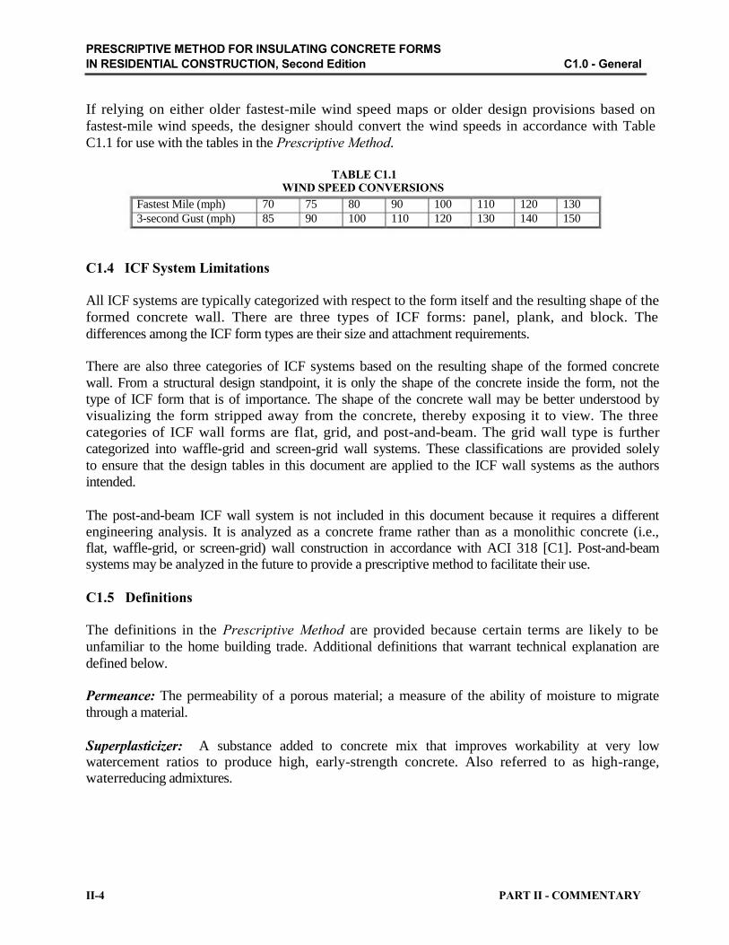
PRESCRIPTIVE METHOD FOR INSULATING CONCRETE FORMS
IN RESIDENTIAL CONSTRUCTION, Second Edition C1.0 - General
If relying on either older fastest-mile wind speed maps or older design provisions based on
fastest-mile wind speeds, the designer should convert the wind speeds in accordance with Table
C1.1 for use with the tables in the Prescriptive Method.
TABLE C1.1 WIND SPEED CONVERSIONS
Fastest Mile (mph) 70 75 80 90 100 110 120 130
3-second Gust (mph) 85 90 100 110 120 130 140 150
C1.4 ICF System Limitations
All ICF systems are typically categorized with respect to the form itself and the resulting shape of the
formed concrete wall. There are three types of ICF forms: panel, plank, and block. The
differences among the ICF form types are their size and attachment requirements.
There are also three categories of ICF systems based on the resulting shape of the formed concrete
wall. From a structural design standpoint, it is only the shape of the concrete inside the form, not the
type of ICF form that is of importance. The shape of the concrete wall may be better understood by
visualizing the form stripped away from the concrete, thereby exposing it to view. The three
categories of ICF wall forms are flat, grid, and post-and-beam. The grid wall type is further
categorized into waffle-grid and screen-grid wall systems. These classifications are provided solely
to ensure that the design tables in this document are applied to the ICF wall systems as the authors
intended.
The post-and-beam ICF wall system is not included in this document because it requires a different
engineering analysis. It is analyzed as a concrete frame rather than as a monolithic concrete (i.e.,
flat, waffle-grid, or screen-grid) wall construction in accordance with ACI 318 [C1]. Post-and-beam systems may be analyzed in the future to provide a prescriptive method to facilitate their use.
C1.5 Definitions
The definitions in the Prescriptive Method are provided because certain terms are likely to be
unfamiliar to the home building trade. Additional definitions that warrant technical explanation are
defined below.
Permeance: The permeability of a porous material; a measure of the ability of moisture to migrate
through a material.
Superplasticizer: A substance added to concrete mix that improves workability at very low watercement ratios to produce high, early-strength concrete. Also referred to as high-range, waterreducing admixtures.
II-4 PART II - COMMENTARY

PRESCRIPTIVE METHOD FOR INSULATING CONCRETE FORMS
IN RESIDENTIAL CONSTRUCTION, Second Edition C2.0 - Materials, Shapes, and Standard Sizes
C2.0 Materials, Shapes, and Standard Sizes
C2.1 Physical Dimensions
Due to industry variations related to the dimensions of ICFs, dimensions were standardized (i.e.,
thickness, width, spacing) to allow for the development of the Prescriptive Method. This
prescriptive approach may result in a conservative design for ICFs where thickness and width are
greater than the minimum allowable or the spacing of vertical cores is less than the maximum
allowable. Consult a design professional if a more economical design is desired.
C2.1.1 Flat ICF Wall Systems
Wall Thickness: The actual wall thickness of flat ICF wall systems is limited to 3.5 inches (89
mm), 5.5 inches (140 mm), 7.5 inches (191 mm), or 9.5 inches (241 mm) in order to
accommodate systems currently available. ICF flat wall manufacturers whose products have a wall thickness different than those listed above shall use the tables in the Prescriptive Method for the nearest available wall thickness that does not exceed the actual wall thickness.
C2.1.2 Waffle-Grid ICF Wall Systems
Core Thickness and Width: The vertical and horizontal core thickness and width are limited per
Table 2.1 in the Prescriptive Method in order to accommodate ICF waffle-grid wall systems
currently available. Variation among the ICF waffle-grid manufacturers is minimal; therefore,
the tables in the Prescriptive Method should produce economical designs for buildings meeting
the applicability limits of Table 1.1 in the Prescriptive Method. ICF waffle-grid manufacturers
that offer concrete cross sections larger than those required in Table 2.1 of the Prescriptive
Method shall use the tables for the nominal size that has the nearest available core thickness not
exceeding the actual wall thickness. Although Figure 2.2 in the Prescriptive Method shows the
ICF waffle-grid vertical core shape as elliptical, the shape of the vertical core may be round,
square, or rectangular provided that the minimum dimensions in Table 2.1 are met.
Core Spacing: The vertical and horizontal core spacing is limited per Table 2.1 of the
Prescriptive Method in order to accommodate the ICF waffle-grid wall systems currently
available. Variation in the products offered by the ICF waffle-grid manufacturers is minimal;
therefore, the tables in the Prescriptive Method should produce economical designs for buildings
meeting the applicability limits of Table 1.1 in the Prescriptive Method.
Web Thickness: The minimum web thickness of 2 inches (51 mm) is based on ICF waffle-grid
systems currently available. Variation in the products offered by the ICF waffle-grid manufacturers is
minimal; therefore, the tables in the Prescriptive Method should produce economical designs for
buildings meeting the applicability limits of Table 1.1 in the Prescriptive Method.
PART II - COMMENTARY II-5

PRESCRIPTIVE METHOD FOR INSULATING CONCRETE FORMS
IN RESIDENTIAL CONSTRUCTION, Second Edition C2.0 - Materials, Shapes, and Standard Sizes
C2.1.3 Screen-Grid ICF Wall System
Core Thickness and Width: The vertical and horizontal core thickness and width are limited per
Table 2.1 in the Prescriptive Method in order to accommodate ICF screen-grid wall systems
currently available. ICF screen-grid manufacturers that offer concrete cross sections larger than
those required in Table 2.1 shall use the tables for the nominal size that has the nearest available
core thickness not exceeding the actual wall thickness. Although Figure 2.3 of the Prescriptive
Method shows the ICF screen-grid vertical core shape as round, the shape of the vertical core
may be square, rectangular, elliptical, or other shape provided that the minimum dimensions in
Table 2.1 are met.
Core Spacing: The vertical and horizontal core spacing is limited per Table 2.1 of the
Prescriptive Method in order to accommodate the large number of ICF screen-grid wall systems
currently available. Due to a lack of test data to suggest otherwise, the maximum allowable
horizontal and vertical core spacing is a value agreed on by the steering committee members.
The core spacing is the main requirement differentiating an ICF screen-grid system from an ICF
post-and-beam system. Future testing is required to determine the maximum allowable core
spacing without adversely affecting the wall system’s ability to act as a wall rather than as a
frame.
C2.2 Concrete Materials
C2.2.1 Concrete Mix
The maximum slump and aggregate size requirements are based on current ICF practice. Considerations included in the prescribed maximums are ease of placement, ability to fill cavities thoroughly, and limiting the pressures exerted on the form by wet concrete.
Concrete for walls less than 8 inches (203 mm) thick is typically placed in the forms by using a 2-
inch- (51-mm-) to 4-inch- (102-mm-) diameter boom or line pump; aggregates larger than the
maximums prescribed may clog the line. To determine the most effective mix, the industry is
planning to conduct experiments that vary slump and aggregate size, and use admixtures (i.e.,
superplasticizers). The research may not produce an industry wide standard due to the variety of
available form material densities and ICF types; therefore, an exception for higher allowable
slumps is provided in the Prescriptive Method.
C2.2.2 Compressive Strength
The minimum concrete compressive strength of 2,500 psi is based on the minimum current ICF
practice, which corresponds to minimum compressive strength permitted by building codes. This
edition of the Prescriptive Method provides adjustment factors in the footnotes of tables that
recognize the benefits of using higher strength concrete. For Seismic Design Categories D1 and D2, a
minimum concrete compressive strength of 3,000 psi is required [C1][C5].
It is believed that concrete cured in ICFs produce higher strengths than conventional concrete
construction because the formwork creates a “moist cure” environment for the concrete;
however, the concrete compressive strength specified herein is based on cylinder tests cured outside the ICF in accordance with ASTM C31 [C7] and ASTM C 39 [C8].
II-6 PART II - COMMENTARY

PRESCRIPTIVE METHOD FOR INSULATING CONCRETE FORMS
IN RESIDENTIAL CONSTRUCTION, Second Edition C2.0 - Materials, Shapes, and Standard Sizes
C2.2.3 Reinforcing Steel
Materials: The Prescriptive Method applies to reinforcing steel with a minimum yield strength of
40 ksi (300 MPa). In certain instances, this prescriptive approach results in a conservative
design for ICFs where reinforcement with a greater yield strength is used. This edition of the
Prescriptive Method provides adjustment factors in the footnotes of tables that recognize the
benefits of using Grade 60 (420 MPa) reinforcing steel. Low-alloy reinforcing steel is required in
Seismic Design Categories D1 and D2 for improved ductility [C1][C5].
Placement: The Prescriptive Method requires vertical and horizontal wall reinforcement to be
placed in the middle third of the wall thickness. The requirements for vertical and horizontal wall
reinforcement placement are based on current construction practice for a large number of ICF
manufacturers. They provide deviations from the center of the wall on which the calculations are
based for reinforcement lap splices and intersections of horizontal and vertical wall
reinforcement.
A few ICF manufacturers produce a groove or loop in the form tie allowing for easier
reinforcement placement. These manufacturers may locate the groove or loop closer to the
interior or exterior face of the wall to reap the maximum benefit from the steel reinforcement; the
location depends on the wall’s loading conditions and is reflected in the exception for basement walls
as well as in the middle-third requirement for above-grade walls.
Lap splices are provided to transfer forces from one bar to another where continuous
reinforcement is not practical. Lap splices are typically necessary at the top of basement and first
story walls, between wall stories, at building corners, and for continuous horizontal wall reinforcement. The lap splice requirements are based on ACI 318 [C1].
C2.3 Form Materials
The materials listed in the Prescriptive Method are based on currently available ICFs. From a
structural standpoint, the material can be anything that has sufficient strength to contain the concrete
during pouring and curing. From a thermal standpoint, the form material should provide the R-value
required by the local building code; however, the required R-value could be met by installing
additional insulation to the exterior of the form, provided that it does not reduce the minimum
concrete dimensions as specified in Section 2.0. From a life-safety standpoint, the form material can
be anything that meets the criteria for flame-spread and smoke development. The Prescriptive
Method addresses other concerns (i.e., water vapor transmission, termite resistance) that must be
considered when using materials other than those specifically listed here. This section is not
intended to exclude the use of either a current or future material provided that the requirements of
this document are met.
PART II - COMMENTARY II-7

PRESCRIPTIVE METHOD FOR INSULATING CONCRETE FORMS
IN RESIDENTIAL CONSTRUCTION, Second Edition C3.0 - Foundations
C3.0 Foundations
C3.1 Footings
The loads imposed on the footings do not vary from those of conventional concrete construction;
however, the Prescriptive Method provides a table for minimum footing widths with ICF
construction. ICF footing forms are currently available and may be used if they meet the
minimum footing dimensions required in Table 3.1 in the Prescriptive Method. Table 3.1 is
similar to the requirements in the IRC [C4] for 8-inch- (203-mm-) solid or fully grouted
masonry. The minimum footing width values are based on a 28-foot- (8.5-m-) wide building.
Minimum footing widths are based on the maximum loading conditions found in Table 1.1 of the
Prescriptive Method, a minimum footing depth of 12 inches (305 mm) below grade, unsupported
wall story heights up to 10 feet (3 m), and the assumption that all stories are the same thickness and
are constructed of ICFs unless otherwise noted.
The values in Table 3.1 of the Prescriptive Method for a one-story ICF structure account for one
ICF story above-grade. The values in Table 3.1 for a two-story ICF structure account for two ICF
stories above-grade. The values in the table account for an ICF basement wall in all cases.
Footnote 1 to Table 3.1 in the Prescriptive Method provides guidance for sizing an unreinforced
footing based on rule of thumb. This requirement may be relaxed when a professional designs
the footing. Soil borings are rarely required for residential construction except where there are
known risks or a history of problems (i.e., organic deposits, landfills, expansive soils) associated
with building in certain areas. For an approximate relationship between soil type and
loadbearing value, refer to Table C3.1.
C3.2 ICF Foundation Wall Requirements
The Prescriptive Method provides reinforcement tables for foundation walls constructed within the applicability limits of Table 1.1 in the Prescriptive Method. The maximum design conditions are Seismic Design Category D2, ground snow load of 70 psf (3.4 kPa), and equivalent fluid density of
60 pcf (960 kg/m3). The Prescriptive Method provides the minimum required vertical and horizontal
wall reinforcement for various equivalent fluid densities, wall heights, and unbalanced backfill
heights. Vertical wall reinforcement tables are limited to foundation walls (non load-bearing) with
unsupported wall heights up to 10 feet (3 m).
Residential construction makes widespread use of 8-foot (2.4-m) walls; however, ICF homes are
often constructed with higher ceilings. Walls are grouped into three categories as follows:
• walls with soil backfill having a maximum 30 pcf (481 kg/m3) equivalent fluid density;
• walls with soil backfill having a maximum 45 pcf (721 kg/m3) equivalent fluid density;
• walls with soil backfill having a maximum 60 pcf (960 kg/m3) equivalent fluid density.
The following design assumptions were used to analyze the walls:
II-8 PART II - COMMENTARY

PRESCRIPTIVE METHOD FOR INSULATING CONCRETE FORMS
IN RESIDENTIAL CONSTRUCTION, Second Edition C3.0 - Foundations
• Walls support either one or two stories above. The load case considered in the
development of the second edition of the Prescriptive Method is conservative in that no
dead, live or other gravity loads are considered which would increase the moment
capacity, even with considerable eccentricity of axial load toward the outside face of the
foundation wall. This method is consistent with the development of the plain concrete
and reinforced concrete ICF foundation wall provisions in the International Residential
Code [C4].
• Walls are simply supported at the top and bottom of each story.
• Walls contain no openings.
• Bracing is provided for the wall by the floors above and floor slabs below.
• Roof slopes range from 0:12 to 12:12.
• Deflection criterion is the height of the wall, in inches, divided by 240.
Deflection limits are primarily established with regard to serviceability concerns. The intent is to
prevent excessive deflection, which may result in cracking of finishes. For walls, most codes
generally agree that L/240 represents an acceptable serviceability limit for deflection. For walls with
flexible finishes, less stringent deflection limits may be used. The reader is referred to Appendix B,
Engineering Technical Substantiation for an example calculation for a foundation wall. In cases
where the calculations required no vertical wall reinforcement, a minimum wall reinforcement of one
vertical No. 4 bar at 48 inches (1.2 m) on center is a recommended practice to account for
temperature, shrinkage, potential honeycombing, voids, or construction errors.
Minimum horizontal wall reinforcement is based on recommendations in Design Criteria for
Insulating Concrete Form Wall Systems [C10]. The minimum allows for temperature, shrinkage,
potential honeycombing, voids, or construction errors.
C3.2.1 ICF Walls with Slab-on-Grade
ICF stem wall thickness and height are determined as those which can distribute the building loads
safely to the earth. The stem wall thickness should be greater than or equal to the thickness of the
above-grade wall it supports. Given that stem walls are relatively short and are backfilled on both sides,
lateral earth loads induce a small bending moment in the walls; accordingly, lateral bracing should not
be required before backfilling.
C3.2.2 ICF Crawlspace Walls
Table 3.2 in the Prescriptive Method applies to crawlspace walls 5 feet (1.5 m) or less in height
with a maximum unbalanced backfill height of 4 feet (1.2 m). These values were derived from
the Structural Design of Insulating Concrete Form Walls in Residential Construction [C2].
Loading conditions were based on a maximum 32-foot- (9.8-m-) wide building with the lightest
practical gravity loads experienced in residential construction (i.e., a zero dead load as described
previously). The values for minimum vertical wall reinforcement are based on the controlling
loading condition. For detailed engineering calculations, refer to Appendix B, Engineering
Technical Substantiation. PART II - COMMENTARY II-9

PRESCRIPTIVE METHOD FOR INSULATING CONCRETE FORMS
IN RESIDENTIAL CONSTRUCTION, Second Edition C3.0 - Foundations
Soil borings are rarely required for residential construction except where there are known risks or a
history of problems (i.e., organic deposits, landfills, expansive soils) associated with building in
certain areas. Refer to Table C3.2 for an approximate relationship between soil classifications and
equivalent fluid density [C3].
Backfilling should not occur without lateral support at the top of the wall from either the first
floor structure or temporary bracing unless the backfill height is less than one-half the
crawlspace wall height. This requirement ensures that the backfill does not cause the wall to
overturn. Concrete walls can withstand the higher lateral load created from the backfill when the top
of the wall is braced and axial loads are present on the wall. Typically, providing lateral
bracing at the top of the wall until the structure above is in place is sufficient. Moreover,
backfilling should not occur before seven days after the concrete pour; waiting seven days
typically allows the concrete to reach sufficient strength.
C3.2.3 ICF Basement Walls
Tables 3.3 through 3.9 in the Prescriptive Method pertain to basement walls. The values were
derived from the Structural Design of Insulating Concrete Form Walls in Residential
Construction [C2]. Loading conditions were based on lightest possible gravity loads experienced
in residential construction (i.e., a zero dead load as described previously). The values for
minimum vertical wall reinforcement are based on the controlling loading condition. For detailed
engineering calculations, refer to the Appendix B, Engineering Technical Substantiation.
Soil borings are rarely required for residential construction except where there are known risks or a
history of problems (i.e., organic deposits, landfills, expansive soils) associated with building in
certain areas. Refer to Table C3.2 for an approximate relationship between soil classifications and
equivalent fluid density.
Backfilling should not occur without lateral support at the top of the wall from either the first
floor structure or temporary bracing unless the unbalanced backfill height is less than one-half
the basement wall height. This requirement ensures that the backfill does not cause the wall to
overturn. Concrete walls can withstand the higher lateral loads created from the backfill when the
top of the wall is braced and axial loads are present on the wall. Typically, providing lateral
bracing at the top of the wall until the structure above is in place is sufficient. Moreover,
backfilling should not occur before seven days after the concrete pour; waiting seven days
typically allows the concrete to reach sufficient strength.
C3.3 ICF Foundation Wall Coverings
The requirements for interior covering of habitable spaces are based on current building codes and are
self-explanatory.
It is generally accepted that a monolithic concrete wall is a solid wall through which water and air
cannot readily flow; however, there is a possibility that the concrete wall may have honeycombs,
voids, or hairline cracks through which water may enter. Voids between ICF blocks are inherent in
current screen-grid ICF walls and will allow ground water to enter the structure. As a result, a
moisture barrier on the exterior face of all ICF below-grade walls is generally required and should
be considered good practice. Due to the variety of materials on the market, waterproofing and
damp proofing materials are typically specified by the ICF manufacturer. The limitation in the
II-10 PART II - COMMENTARY

PRESCRIPTIVE METHOD FOR INSULATING CONCRETE FORMS
IN RESIDENTIAL CONSTRUCTION, Second Edition C3.0 - Foundations
Prescriptive Method regarding nonpetroleum-based materials reflects the concern that many ICFs are
usually manufactured of rigid foam plastic, which is generally incompatible with petroleum based
materials.
A vapor retarder may be required on the interior face of the ICF wall in some cases. Test results
have shown a potential exists for condensation occurring on the interior face of above-grade ICFs
with a permeance as little as 0.5 perms in colder climates. Few problems have been reported when the
exterior wall finishes are properly designed and constructed to prevent water intrusion. The reader
is referred to Mitigation of Moisture in Insulating Concrete Form Wall Systems [C11] for more
information on the testing and suggested construction recommendations.
C3.4 Termite Protection Requirements
Termites need wood (cellulose) and moisture to survive. Rigid foam plastic provides termites with no
nutrition but can provide access to the wood structural elements. Recently, some building codes have
prohibited rigid foam plastics for near- or below-grade use in heavy termite infestation areas. Code officials and termite treaters fear that foam insulation provides a “hidden pathway”. Local building
code requirements, a local pest control company, and the ICF manufacturer should be consulted
regarding this concern to determine if additional protection is necessary. A brief list of some possible
termite control measures follow.
• Rely on soil treatment as a primary defense against termites. Periodic retreatment and
inspection should be carried forth by the homeowner or termite treatment company.
• Install termite shields.
• Provide a 6-inch- (152-mm-) high clearance above finish grade around the perimeter of the
structure where the foam has been removed to allow visual detection of termites.
• The use of borate treated ICF forms will kill insects that ingest them, and testing of borate treated EPS foam shows that it reduces tunneling compared to untreated EPS.
TABLE C3.1
LOAD-BEARING SOIL CLASSIFICATION
MINIMUM LOAD-BEARING VALUE
psf (kPa)
2,000 (96)
3,000 (144)
4,000 (192)
> 4,000 (192)
SOIL DESCRIPTION
Clay, sandy clay, silty clay, and clayey silt
Sand, silty sand, clayey sand, silty gravel, and clayey gravel
Sandy gravel and medium-stiff clay
Stiff clay, gravel, sand, sedimentary rock, and crystalline bedrock
TABLE C3.2
EQUIVALENT FLUID DENSITY SOIL CLASSIFICATION
MAXIMUM EQUIVALENT UCS1
FLUID DENSITY pcf (kg/m3) CLASSIFICATION
30 (481) GW, GP, SW, SP, GM
45 (721) GC, SM
60 (961) SC, MH, CL, CH, ML-CL
SOIL
DESCRIPTION
Well-drained, cohesionless soils such as clean (few
or no fines) sand and gravels
Well-drained, cohesionless soils such as sand and
gravels containing silt or clay
Well-drained, inorganic silts and clays that are
broken up into small pieces
1UCS - Uniform Soil Classification system
PART II - COMMENTARY II-11

PRESCRIPTIVE METHOD FOR INSULATING CONCRETE FORMS
IN RESIDENTIAL CONSTRUCTION, Second Edition C4.0 - ICF Above-Grade Walls
C4.0 ICF Above-Grade Walls
C4.1 ICF Above-Grade Wall Requirements
The Prescriptive Method provides reinforcement tables for walls constructed above-grade within the
applicability limits of Table 1.1 in the Prescriptive Method. The maximum design conditions are
Seismic Design Category D2, ground snow load of 70 psf (3.4 kPa), and a design wind pressure of 80
psf (3.8 kPa). The Prescriptive Method provides the minimum required vertical and horizontal wall
reinforcement for different design wind pressures and wall heights. Vertical wall reinforcement tables
are limited to one- and two-story buildings for non-load bearing and load-bearing walls laterally
unsupported up to 10 feet (3 m).
Residential construction makes widespread use of 8-foot (2.4-m) walls; however, ICF homes are
often constructed with higher ceilings. Walls are grouped into three categories as follows:
• walls for one-story or the second floor of a two-story building (supporting a roof only);
• walls for the first story of a two-story building where the second story is light-frame
construction (supporting light-frame second story and roof); and
• walls for the first story of a two-story building where the second story is ICF construction (supporting ICF second story and roof).
The following design assumptions were made in analyzing the walls:
• Walls are simply supported at each floor and roof providing lateral support.
• Walls contain no openings.
• Lateral support is provided for the wall by the floors, slab-on-grade, and roof.
• Roof slopes range from 0:12 to 12:12.
• Deflection criterion is the laterally unsupported height of the wall, in inches, divided by 240.
• The minimum possible axial load is considered for each case.
• Wind loads were calculated in accordance with ASCE 7 [C3] using components and
cladding coefficients, interior zone, and mean roof height of 35 feet (11 m).
Deflection limits are primarily established with regard to serviceability concerns. The intent is to prevent excessive deflection, which may result in cracking of finishes. For walls, most codes
generally agree that L/240 represents an acceptable serviceability limit for deflection. For walls with flexible finishes, less stringent deflection limits may be used. The reader is referred to Appendix B,
Engineering Technical Substantiation for an example calculation for an above-grade wall. In cases
where the calculations required no vertical wall reinforcement, the following minimum wall
reinforcement is required.
A minimum of one vertical No. 4 bar at 48 inches (1.2 m) on center is required for all above-grade
wall applications. This requirement establishes a minimum “good practice” in ICF construction
and provides for crack control, continuity, and a “safety factor” for conditions where concrete
consolidation cannot be verified due to the stay-in-place formwork. In addition, structural testing
was conducted at the NAHB Research Center, Inc. to determine the in-plane shear resistance of
concrete walls cast with ICFs [C9]. All test specimens had one No. 4 vertical bar at 48 inches on
II-12 PART II - COMMENTARY
PRESCRIPTIVE METHOD FOR INSULATING CONCRETE FORMS
IN RESIDENTIAL CONSTRUCTION, Second Edition C4.0 - ICF Above-Grade Walls
center. Upon review of the data, this requirement allows the in-plane shear analysis to be
calculated as reinforced concrete instead of plain structural concrete. This allows for lower
minimum solid wall lengths for wind and seismic design. This minimum reinforcement allows all
shear walls to be analyzed identically and provides consistency in all table values. Details on the
analysis approach are found in Appendix B.
Minimum horizontal wall reinforcement is based on recommendations in Design Criteria for
Insulating Concrete Form Wall Systems [C10]. The minimum allows for temperature, shrinkage, or
potential construction errors.
The more stringent requirement that vertical wall reinforcement be terminated with a bend or hook in
high wind areas is based on current standards for conventional masonry construction. The
requirement has proven very effective in masonry construction in conditions with wind speeds 110
mph (177 km/hr) or greater. The bend or hook provides additional tensile strength in the concrete wall
to resist the large roof uplift loads in high wind areas. A similar detailing requirement is used in high
seismic conditions as required in ACI 318 [C1].
C4.2 ICF Above-Grade Wall Coverings
The requirements for interior covering of habitable spaces are based on current building codes
and are self-explanatory.
It is generally accepted that a monolithic concrete wall is a solid wall through which water and air
cannot readily flow; however, there is a possibility that the concrete wall may have honeycombs,
voids, or hairline cracks through which water may enter. Voids between ICF blocks are inherent in
current screen-grid ICF walls and may allow water to enter the structure. As a result, a moisture
barrier on the exterior face of the ICF wall is generally required and should be considered good
practice.
A vapor retarder may also be required on the interior face of the ICF wall in some cases. Test results
have shown a potential exists for condensation occurring on the interior face of above-grade ICFs
with a permeance as little as 0.5 perms in colder climates. Few problems have been reported when the
exterior wall finishes are properly designed and constructed to prevent water intrusion. The reader
is referred to Mitigation of Moisture in Insulating Concrete Form Wall Systems [C11] for more
information on the testing and suggested construction recommendations.
PART II - COMMENTARY II-13

PRESCRIPTIVE METHOD FOR INSULATING CONCRETE FORMS
IN RESIDENTIAL CONSTRUCTION, Second Edition C5.0 - ICF Wall Opening Requirements
C5.0 ICF Wall Opening Requirements
C5.1 Minimum Length of ICF Wall without Openings
The tables in Sections 3.0 and 4.0 are based on ICF walls without door or window openings. This
simplified approach rarely arises in residential construction since walls generally contain windows and
doors to meet functional needs. The amount of openings affects the lateral (racking) strength of the
building parallel to the wall, particularly for wind and seismic loading conditions. The
Prescriptive Method provides recommendations for the amount and placement location of
additional reinforcement required around openings. It also addresses the minimum amount of solid
wall required to resist in-plane shear loads from wind and seismic forces.
The values for the minimum solid wall length along exterior wall lines listed in Tables 5.2 to 5.5 of the
Prescriptive Method were calculated using the main wind force resisting wind loads and seismic loads in
accordance with ASCE 7 [C3] and the IBC [C5]. The ICF solid wall amounts were checked using
resistance models for buildings with differing dimensions.
A shear model following the methods outlined in UBC Chapter 21 regarding shear walls was used
[C12]. This method linearly varies the resistance of a wall segment from a cantilevered beam model
at an aspect ratio (height-to-width) greater than 4.0 to a solid shear wall for all segments less than
2.0. The Prescriptive Method requires all walls to have a minimum 2 foot (0.6 m) solid wall
segment adjacent to all corners. Therefore, the flexural capacity of the 2 foot (0.6 m) elements at the
corners of the walls was first determined. This value was then subtracted from the required design
load for the wall line, resulting in the design load required by the remainder of the wall. The amount of
solid wall required to resist the remaining load was determined using shear elements. Refer to
Appendix B for detailed calculations.
For Seismic Design Categories D1 and D2, all walls are required to have a minimum 4 foot (1.2 m)
solid wall segment adjacent to all corners. In addition, all wall segments in the wall line are required to
have minimum 4 foot (1.2 m) solid wall segments in order to be included in the total wall length. This
requirement is based on tested performance [C9].
C5.2 Reinforcement around Openings
The requirements for number and placement of reinforcement around openings in the Prescriptive
Method are based on ACI [C1] and IBC [C5]. Per ACI [C1], the designer is required to provide two
No. 5 bars on each side of all window and door openings; this is considered impractical for
residential ICF construction. The IBC [C5] has clauses modifying this requirement to one No. 4 bar,
provided that the vertical bars span continuously from support to support and that horizontal bars
extend a minimum of 24 inches (610 mm) beyond the opening. The requirement for two No. 4 bars or
one No. 5 bar in locations with 3-second gust design wind speeds greater than 110 mph (177 km/hr)
is provided to resist uplift loads.
II-14 PART II - COMMENTARY

PRESCRIPTIVE METHOD FOR INSULATING CONCRETE FORMS
IN RESIDENTIAL CONSTRUCTION, Second Edition C5.0 - ICF Wall Opening Requirements
C5.3 Lintels
C5.3.1 Load-Bearing ICF Wall Lintels
Lintels are horizontal members used to transfer wall, floor, roof, and attic dead and live loads
around openings in walls. Lintels are divided into three categories as follows:
• lintels in a one-story building or in the second story of a two-story building (supporting a
roof only);
• lintels in the first story of a two-story building where the second story is light-frame
construction (supporting light-frame second story and roof); and
• lintels in the first story of a two-story building where the second story is ICF construction (supporting ICF second story and roof).
The following design assumptions were made in analyzing the lintels:
• Lintels have fixed end restraints since the walls and lintels are cast monolithically.
• A vertical core occurs at each end of the lintel for proper bearing.
• Lateral resistance is provided for the lintel by the floor or roof system above.
• Roof slopes range from 0:12 to 12:12.
• Deflection criterion is the clear span of the lintel, in inches, divided by 240.
• Ceilings, roofs, attics, and floors span the full width of the house (assume no interior load-
bearing walls or beams).
• Floor and roof clear span is maximum 32 feet (9.8 m).
• Roof snow loads were calculated by multiplying the ground snow load by 0.7. Therefore,
the roof snow load was taken as P = 0.7Pg, where Pg is the ground snow load in pounds per
square foot.
• Loads experienced by the lintel are uniform loads and do not take into account any arching
action that might occur because opening locations above the lintel cannot be determined for
all cases.
• Shear reinforcement in the form of No. 3 stirrups are provided based on ACI [C1] and lintel
test results; refer to Lintel Testing for Reduced Shear Reinforcement in Insulating Concrete
Form Systems [C13] and Testing and Design of Lintels Using Insulating Concrete Forms
[C14].
All live and dead loads from the roof, attic, floor, wall above, and lintel itself were taken into
account in the calculations using the ACI 318 [C1] load combination, U = 1.4D + 1.7L. Adjustment
factors are provided for clear spans of 28 feet (8.5 m) and 24 feet (7.3 m). Typically, the full dead
load and a percentage of the live load is considered in lintel analysis where information regarding
opening placement in the story is known. The area of load combinations or lintels, particularly when
multiple transient live loads from various areas of the building are considered, must be refined to
produce more economical and rational designs.
PART II - COMMENTARY II-15
PRESCRIPTIVE METHOD FOR INSULATING CONCRETE FORMS
IN RESIDENTIAL CONSTRUCTION, Second Edition C5.0 - ICF Wall Opening Requirements
The calculations are based on the lintel occurring in an above-grade wall with a floor live load of 30 psf
(1.4 kPa). Due to the conservative nature of the lintel load analysis, the tables may be used for lintels
located in foundation walls where the maximum floor live load is 40 psf (1.9 kPa) and additional
wall dead loads from the story above are present.
Deflection limits are established primarily with regard to serviceability concerns. The intent is to
prevent excessive deflection that may result in cracking of finishes. Windows and doors are also
sensitive to damage caused by excessive lintel deflection; therefore, a conservative deflection limit
of L/480 for service dead loads and sustained live loads is often suggested. This limit is very
conservative when the installation of the window and door components is properly detailed.
Accounting for the conservative lintel load analysis discussed above, L/240 for full service dead and
live loads was used. The lintel section is assumed cracked and a stiffness factor of 0.1EcIg is used in
accordance with test results and recommendations made in Design Criteria for Insulating Concrete
Form Wall Systems [C10].
Additional tables are provided in the second edition of the Prescriptive Method to provide
additional options for lintels. Many of the new tables are based on the design methodologies
outlined in the research report entitled Testing and Design of Lintels Using Insulating Concrete
Forms [C14]. The reader is referred to Appendix B, Engineering Technical Substantiation for
example calculations of lintels in bearing walls.
Because the maximum allowable lintel spans seldom account for garage door openings in homes
with a story above using a single No. 4 or No. 5 bottom bar for lintel reinforcement, requirements
are provided for larger wall openings such as those commonly used for one- and two-car garage
doors.
C5.3.2 ICF Non Load-Bearing Wall Lintels
Lintels are horizontal members used to transfer wall dead loads around openings in non loadbearing walls. Lintels are divided into two categories as follows:
• lintels in a one-story building or the second story of a two-story building and where the
gable end wall is light-frame construction (supporting light-frame gable end wall); and
• lintels in the first story of a two-story building where the second story is ICF construction
(supporting ICF second-story gable end wall).
The following design assumptions were made in analyzing the lintels:
• Lintels have fixed end restraints since the walls and lintels are cast monolithically.
• A vertical core occurs at each end of the lintel for proper bearing.
• Lateral resistance is provided for the lintel by the floor or roof system above.
• Deflection criterion is the clear span of the lintel, in inches, divided by 240.
• Lintels support only dead loads from the wall above.
Loads experienced by the lintel are uniform loads and do not take into account any arching action
that might occur above the lintel within a height equal to the lintel clear span because opening
II-16 PART II - COMMENTARY

PRESCRIPTIVE METHOD FOR INSULATING CONCRETE FORMS
IN RESIDENTIAL CONSTRUCTION, Second Edition C5.0 - ICF Wall Opening Requirements
locations above the lintel cannot be determined for all cases. Lintel dead weight and the dead load of
the wall above were taken into account in the calculations using ACI 318 [C1] load combination, U
= 1.4D + 1.7L. This analysis is conservative because arching action is not accounted for above the
lintel within a height equal to the lintel clear span because wall opening locations above the lintel
cannot be determined for all cases. The calculations are based on the lintel occurring in an above-
grade wall. Due to the conservative nature of the lintel load analysis, the tables may be used for
foundation walls where additional wall dead loads from the story above may be present.
Deflection limits are established primarily with regard to serviceability concerns. The intent is to
prevent excessive deflection that may result in cracking of finishes. Windows and doors are also
sensitive to damage caused by lintel deflection; therefore, a conservative deflection limit of L/480 for service dead loads and sustained live loads is often suggested. This limit is very conservative
when the installation of window and door components is properly detailed. Accounting for the
conservative lintel load analysis discussed above, L/240 for full service dead and full service live
loads was used.
The lintel section is assumed cracked and a stiffness factor of 0.1EcIg is used in accordance with test
results and recommendations made in Design Criteria for ICF Wall Systems [C10]. The reader is referred to Appendix B, Engineering Technical Substantiation for an example calculation of a non
load-bearing lintel.
PART II - COMMENTARY II-17

PRESCRIPTIVE METHOD FOR INSULATING CONCRETE FORMS
IN RESIDENTIAL CONSTRUCTION, Second Edition C6.0 - ICF Connection Requirements
C6.0 ICF Connection Requirements
C6.1 ICF Foundation Wall-to-Footing Connection
The requirements of the Prescriptive Method are based on typical residential construction
practice for light-frame construction. Due to the heavier axial loads of ICF construction,
frictional resistance at the footing-ICF wall interface is higher and provides a greater factor of
safety than in light-frame residential construction except for Seismic Design Categories D1 and D2
where dowels are required.
C6.2 ICF Wall-to-Floor Connection
C6.2.1 Floor on ICF Wall Connection (Top-Bearing Connection)
The requirements of the Prescriptive Method are based on typical residential construction and the IRC [C4] for foundations constructed of concrete or masonry units. In high wind and high
seismic conditions, connections are analyzed and detailed in accordance with ACI [C1] and the
IBC [C5].
C6.2.2 Floor Ledger-ICF Wall Connection (Side-Bearing Connection)
The requirements of the Prescriptive Method are based on the Structural Design of Insulating
Concrete Form Walls in Residential Construction [C2]. Although other materials, such as cold-
formed metal framing and concrete plank systems, may be used for the construction of floors in
ICF construction, the majority of current ICF residential construction uses wood floor framing.
Consult the manufacturer for proper connection details when using floor systems constructed of
other materials. Consult a design professional when constructing buildings with floor systems
which exceed the limits set forth in Table 1.1 of the Prescriptive Method. In high wind and high
seismic conditions, connections are analyzed and detailed in accordance with ACI [C1] and the
IBC [C5].
C6.3 ICF Wall-to-Roof Connection
The requirements of the Prescriptive Method are based on typical residential construction and the IRC [C4] for walls constructed of concrete or masonry units. In high wind and high seismic
conditions, connections are analyzed and detailed in accordance with ACI [C1] and the IBC
[C5].
II-18 PART II - COMMENTARY

PRESCRIPTIVE METHOD FOR INSULATING CONCRETE FORMS
IN RESIDENTIAL CONSTRUCTION, Second Edition C7.0 - Utilities
C7.0 Utilities
C7.1 Plumbing Systems
Due to the different ICF materials available, the reader is advised to refer to the local building
code for guidance.
Typical construction practice with ICFs made of rigid plastic foam calls for cutting a chase into the
foam for small pipes. Almost all ICFs made of rigid plastic foam will accommodate up to a 1-inch-
(25-mm-) diameter pipe and some may accommodate up to a 2-inch- (51-mm-) diameter pipe. The
pipes are typically fastened to the concrete with plastic or metal ties or concrete nails. The foam is
then replaced with adhesive foam installed over the pipe. Larger pipes are typically installed on
the inside face of the wall with a chase constructed around the pipe to conceal it; alternatively,
pipes are routed through interior light-frame walls.
C7.2 HVAC Systems
Due to the different ICF materials available, the reader is advised to refer to the local building
code for guidance.
ICF walls are considered to have high R-values and low air infiltration rates; therefore HVAC equipment may be sized smaller than in typical light-frame construction. Refer to Sizing AirConditioning and Heating Equipment for Residential Buildings with ICF Walls [C15].
C7.3 Electrical Systems
Due to the different ICF materials available, the reader is advised to refer to the local building
code and the ICF manufacturer for guidance.
PART II - COMMENTARY II-19

PRESCRIPTIVE METHOD FOR INSULATING CONCRETE FORMS
IN RESIDENTIAL CONSTRUCTION, Second Edition C8.0 - Construction and Thermal Guidelines
C8.0 Construction and Thermal Guidelines The construction and thermal guidelines are provided to supplement the requirements of the
Prescriptive Method and are considered good construction practices. These guidelines should not be
considered comprehensive. Manufacturer’s catalogs, recommendations, and other technical
literature should also be consulted. Refer to Guidelines for Using the CABO Model Energy Code with
Insulating Concrete Forms [C16].
Proper fasteners and tools are essential to any trade. Tables C8.1 and C8.2 provide a list of
fasteners and tools that are commonly used in residential ICF construction. Adhesives used on foam
forms shall be compatible with the form material. TABLE C8.1
TYPICAL FASTENERS FOR USE WITH ICFs
FASTENER TYPE
Galvanized nails, ringed nails, and drywall
screws
Adhesives
Anchor bolts or steel straps
Duplex nails
Concrete nails or screw anchors
II-20
USE/APPLICATION
Attaching items to furring strips or form fastening surfaces
Attaching items to form for light- and medium-duty connections such as
gypsum wallboard and base trim
Attaching structural items to concrete core for medium- and heavy-duty
connections such as floor ledger board and sill plate
Attaching items to concrete core for medium-duty connections Attaching
items to concrete core for medium-duty connections such as interior
light-frame partitions to exterior ICF walls
PART II - COMMENTARY

PRESCRIPTIVE METHOD FOR INSULATING CONCRETE FORMS
IN RESIDENTIAL CONSTRUCTION, Second Edition C8.0 - Construction and Thermal Guidelines
TABLE C8.2
RECOMMENDED TOOLS FOR ICF CONSTRUCTION
TOOL
CUTTING
Drywall saw
Keyhole saw
PVC or miter saw
Rasp or coarse sandpaper
Hand saw
Circular saw
Reciprocating saw
Thermal cutter
Utility knife
Router
Hot knife
MISCELLANEOUS
Mason’s trowel
Wood glue, construction
adhesive, or adhesive foam
Cutter-bender
Small-gauge wire or precut
tie wire or wire spool
Nylon tape
Nylon twine
Chalk line
Tin snips
MOVING/PLACING
Forklift, manual lift, or
boom or crane truck
Chute
Line pump
Boom pump
PART II - COMMENTARY
USE/
APPLICATION
Small, straight, or curved cuts and holes
Precise holes for utility penetrations
Small, straight cuts and for shaving edges of forms
Shaving edges of forms; removing small high spots after
concrete pour
Fast, straight cuts
Fast, precise cuts; ensure proper blade is used
Fast cuts, good for utility cuts, ensure proper blade is used
Fast, very precise cuts; removing large bulges in wall after
concrete pour
Small, straight, or curved cuts and holes
Fast, precise utility cuts; use with 1/2-inch drive for deep
cutting
Fast, very precise utility cuts
Leveling concrete after pour; striking excess concrete from
form after pour
Applying thin mortar bed to forms
Gluing forms together at joints
Cutting and bending steel reinforcement to required lengths
and shapes
Tying horizontal and vertical reinforcement together
Reinforcing seams before concrete is poured Tying
horizontal and vertical reinforcement together
Plumbing walls and foundation
Cutting metal form ties
Carrying large units or crates of units and setting them in
place
Placing concrete in forms for below-grade pours
Placing concrete in forms; use with a 2-inch hose
Placing concrete in forms; use with two “S” couplings and
reduce the hose to a 2-inch diameter
APPLICABLE
FORM
MATERIAL
Foam
All
Foam
Foam
All
All
All
Foam
Foam
Foam
Foam
All
Composite
Foam
All
All
Foam
All
All
Foam
All
All
All
All
II-21

PRESCRIPTIVE METHOD FOR INSULATING CONCRETE FORMS
IN RESIDENTIAL CONSTRUCTION, Second Edition C9.0 - References
C9.0 References
[C1] Building Code Requirements for Structural Concrete (ACI 318-99). American Concrete
Institute, Detroit, Michigan. 1999.
[C2] Structural Design of Insulating Concrete Form Walls in Residential Construction. Portland Cement Association, Skokie, Illinois. 1998.
[C3] Minimum Design Loads for Buildings and Other Structures (ASCE 7-98). American
Society of Civil Engineers, New York, New York. 1998.
[C4] International Residential Code. International Code Council (ICC). Falls Church,
Virginia. 2000.
[C5] International Building Code. International Code Council (ICC). Falls Church, Virginia.
2000.
[C6] Guide to Residential Cast-in-Place Concrete Construction (ACI 322R-84). American
Concrete Institute, Detroit, Michigan. 1984.
[C7] ASTM C 31/C 31M-96 Standard Practice for Making and Curing Concrete Test Specimens in the Field. American Society for Testing and Materials (ASTM), West
Conshohocken, Pennsylvania. 1997.
[C8] ASTM C 39-96 Standard Test Method for Compressive Strength of Cylindrical Concrete
Specimens. American Society for Testing and Materials (ASTM), West Conshohocken, Pennsylvania. 1996.
[C9] In-Plane Shear Resistance of Insulating Concrete Form Walls. Prepared for the U.S. Department of Housing and Urban Development, Portland Cement Association, and the National
Association of Home Builders by the NAHB Research Center, Inc., Upper Marlboro, Maryland. 2001
[C10] Design Criteria for Insulating Concrete Form Wall Systems, (RP 116). Prepared for the
Portland Cement Association by Construction Technology Laboratories, Inc., Skokie, Illinois.
1996.
[C11] Mitigation of Moisture in Insulating Concrete Form Wall Systems. Prepared for the
Portland Cement Association by Construction Technology Laboratories, Inc., Skokie, Illinois.
1998.
[C12] Uniform Building Code. International Conference of Building Officials. Whittier, California.
1997.
II-22 PART II - COMMENTARY

PRESCRIPTIVE METHOD FOR INSULATING CONCRETE FORMS
IN RESIDENTIAL CONSTRUCTION, Second Edition C9.0 - References
[C13] Lintel Testing for Reduced Shear Reinforcement in Insulating Concrete Form Systems .
Prepared for the U.S. Department of Housing and Urban Development, Portland Cement
Association, and the National Association of Home Builders by NAHB Research Center, Inc.,
Upper Marlboro, Maryland. 1998.
[C14] Testing and Design of Lintels Using Insulating Concrete Forms, Prepared for the U.S.
Department of Housing and Urban Development, Portland Cement Association, and the National
Association of Home Builders by the NAHB Research Center, Inc., Upper Marlboro, Maryland.
2000.
[C15] Sizing Air-Conditioning and Heating Equipment for Residential Buildings with ICF
Walls, (No. 2159). Prepared for the Portland Cement Association by Construction Technology
Laboratories, Inc., Skokie, Illinois. 1998.
[C16] Guidelines for Using the CABO Model Energy Code with Insulating Concrete Forms (No.
2150). Prepared for the Portland Cement Association by Construction Technology Laboratories, Inc.,
Skokie, Illinois. 1998.
PART II - COMMENTARY II-23