Embed Size (px)
Citation preview

Copyr ight © 2 0 0 8 Am er ican Forest & Paper Associa t io n, I nc.
Prescriptive Residential Wood
Deck Construction Guide Based on the 2006 International Residential Code
Where applicable, provisions and details contained in this document are based on the International Residential Code (IRC) [bracketed text references applicable sections of the IRC]. Prescriptive construction methods recommended meet or exceed minimum requirements of the IRC. Provisions that are not found in the IRC are recommended as good industry practice. Where differences exist between provisions of this document and the IRC, provisions of the IRC shall apply. This document is not intended to preclude the use of other construction methods or materials. All construction and materials must be approved by the authority having jurisdiction. Every effort has been made to reflect the language and intent of the IRC. However, no assurance can be given that designs and construction made in accordance with this document meet the requirements of any particular jurisdiction.

2 PRESCRIPTIVE RESIDENTIAL WOOD DECK CONSTRUCTION GUIDE
Am er ican W ood Council
CONTENTS
MINIMUM REQUIREMENTS..........................................2
DECKING REQUIREMENTS...........................................3
JOIST SIZE.........................................................................3
BEAM SIZE & ASSEMBLY REQUIREMENTS .............5
DECK FRAMING PLAN...................................................6
JOIST-TO-BEAM CONNECTION....................................7
JOIST HANGERS ..............................................................7
POST REQUIREMENTS...................................................7
RIM JOIST REQUIREMENTS..........................................8
FOOTINGS.........................................................................9
LEDGER ATTACHMENT REQUIREMENTS...............10
PROHIBITED LEDGER ATTACHMENTS................... 12
LEDGER BOARD FASTENERS .................................... 12
FREE-STANDING DECKS............................................. 14
DECK STABILITY.......................................................... 14
GUARD REQUIREMENTS ............................................ 15
GUARD POST ATTACHMENTS .................................. 16
STAIR REQUIREMENTS............................................... 17
STAIR HANDRAIL REQUIREMENTS......................... 18
STAIR FOOTING REQUIREMENTS ............................ 19
STAIR LIGHTING REQUIREMENTS........................... 19
FRAMING AT CHIMNEY OR BAY WINDOW ........... 19
MINIMUM REQUIREMENTS
1. This document applies to single level residential
wood decks only.
2. All lumber shall be identified by the grade mark of,
or certificate of inspection issued by, an approved
lumber grading or inspection bureau or agency
(www.alsc.org). All lumber shall be a naturally
durable species (such as Redwood or Western
Cedars) or be pressure-treated with an approved
process and preservative in accordance with
American Wood Protection Association standards
(Table 1) [R319.1 and R320.1]. All lumber in
contact with the ground shall be approved
preservative treated wood suitable for ground
contact. [R319.1.2]
3. All nails shall meet the requirements of ASTM F
1667. Wood screws shall meet the requirements of
ANSI/ASME B18.6.1. Bolts and lag screws shall
meet the requirements of ANSI/ASME B18.2.1.
4. To resist corrosion, the following is required
[R319.3]:
All screws, bolts, and nails for use with
preservative treated wood shall be hot-dipped
galvanized, stainless steel, silicon bronze or
copper. Fasteners to be hot-dipped galvanized
shall meet the requirements of ASTM A 153,
Standard Specification for Zinc Coating (Hot-
Dip) on Iron and Steel Hardware, Class D for
fasteners 3/8" in diameter and smaller or Class C
for fasteners with diameters over 3/8".
Fasteners other than nails and timber rivets shall
be permitted to be of mechanically deposited
zinc-coated steel with coating weights in
accordance with ASTM B 695, Class 55,
minimum.
All hardware (joist hangers, cast-in-place post
anchors, etc.) shall be galvanized or shall be
stainless steel. Hardware to be hot-dipped prior
to fabrication shall meet ASTM A 653, Standard
Specification for Steel Sheet, Zinc-Coated
(Galvanized) or Zinc-Iron Alloy-Coated
(Galvannealed) by the Hot-Dip Process, G-185
coating. Hardware to be hot-dipped galvanized
after fabrication shall meet ASTM A123,
Specification for Zinc (Hot-Dip Galvanized)
Coatings on Iron and Steel Products.
Fasteners and connectors exposed to, and
located within 300 feet of, a salt water shoreline
shall be stainless steel grade 304 or 316.
Other coated or non-ferrous fasteners or
hardware shall be as approved by the authority
having jurisdiction.
5. Decks supporting hot tubs are beyond the scope of
this document.
6. This document does not apply to decks which will
experience snow loads, snow drift loads, or sliding
snow loads that exceed 40 psf. This document does
not address lateral loads on decks such as wind or
seismic.
7. Flashing shall be corrosion-resistant metal of
minimum nominal 0.019-inch thickness or approved
non-metallic material [R703.8].
8. Decks shall not be used or occupied until final
inspection and approval is obtained.
9. This document is not intended to preclude the use of
other construction methods or materials not shown
herein.

PRESCRIPTIVE RESIDENTIAL WOOD DECK CONSTRUCTION GUIDE 3
Am er ican Forest & Paper Associa t ion
Table 1. Common preservative treatments and retention levels (pcf) for sawn lumber in ground contact.a
Species ACQ-B ACQ-C ACQ-D CA-B CuN-W
Southern Pine 0.40 0.40 0.40 0.21 0.11
Douglas Fir-Larch 0.40 0.40 NR 0.21 0.11
Hem-Fir 0.40 0.40 0.40 0.21 0.11
Ponderosa Pine 0.40 0.40 0.40 0.21 0.11
Red Pine 0.40 0.40 0.40 0.21 0.11
Spruce-Pine-Fir NR 0.40 NR NR NR
Redwood NR NR NR NR NR a Preservatives and retentions listed in Table 1 are based on the American Wood Protection
Association (AWPA) Book of Standards. NR = Treatments Not Recommended.
DECKING REQUIREMENTS
All decking material shall be composed of dimension
lumber (2" nominal thickness) or span rated decking in
accordance with the American Lumber Standard
Committee Policy for Evaluation of Recommended
Spans for Span Rated Decking Products (November 5,
2004). Attach decking to each joist with 2-8d threaded
nails or 2-#8 screws. Space decking boards
approximately 1/8" apart. See Figure 11 for decking
connection requirements at the rim joist. Decking may
be placed from an angle perpendicular to the joists to an
angle of 45 degrees to the joists. Each segment of
decking must bear on a minimum of 4 joists.
Decking not meeting the above requirements may be
substituted when the product has been approved by the
authority having jurisdiction.
JOIST SIZE
The span of a joist is measured from the centerline of
bearing at one end of the joist to the centerline of bearing
at the other end of the joist and does not include the
length of the overhangs. Use Table 2 to determine joist
span based on lumber size and joist spacing. See Figure
1 and Figure 2 for joist span types.
Table 2. Maximum Joist Spans (LJ)1
Joist Spacing (o.c.)
Species Size 12" 16" 24"
2x8 10' - 6" 10' - 6" 10' - 2"
2x10 15' - 2" 15' - 2" 13' - 1"Southern Pine
2x12 18' - 0" 18' - 0" 15' - 5"
2x8 9' - 3" 9' - 3" 9' - 1"
2x10 13' - 4" 13' - 4" 11' - 1"
Douglas Fir-Larch, Hem-
Fir, SPF2
2x12 17' -10" 15' - 9" 12' -10"
2x8 8' - 4" 8' - 4" 8' - 4"
2x10 12' - 0" 12' - 0" 10' - 7"
Redwood, Western Cedars,
Ponderosa Pine3,
Red Pine3 2x12 16' - 1" 15' - 1" 12' - 3"
1. Assumes 40 psf live load, 10 psf dead load, L/180 cantilever deflection with 230 lb point load, No. 2 grade, and wet service conditions. See span calculator at www.awc.org for simple span conditions without cantilevers. 2. Incising assumed for refractory species including Douglas fir-larch, hem-fir, and spruce-pine-fir. 3. Design values based on northern species with no incising assumed.

4 PRESCRIPTIVE RESIDENTIAL WOOD DECK CONSTRUCTION GUIDE
Am er ican W ood Council
Figure 1A: Joist Span – Deck Attached at House and Bearing Over Beam
Figure 1B: Joist Span – Joists Attached at House and to Side of Beam
Figure 2: Joist Span – Free Standing Deck

PRESCRIPTIVE RESIDENTIAL WOOD DECK CONSTRUCTION GUIDE 5
Am er ican Forest & Paper Associa t ion
BEAM SIZE & ASSEMBLY REQUIREMENTS
Deck beam spans shall be in accordance with Table 3
and can extend past the post centerline up to LB/4 as
shown in Figure 3. Joists may bear on the beam and
extend past the beam centerline up to LJ/4 as shown in
Figures 1A and 2, or the joists may attach to the side of
the beam with joist hangers as shown in Figure 1B
(however, joists shall not be attached to opposite sides of
the same beam). See JOIST-TO-BEAM CONNECTION
details, Figure 6.
Where multiple 2x members are used, the deck’s beam is
assembled by attaching the members identified in Table
3 in accordance with Figure 4. [R602.3(1)]
Table 3. Deck Beam Spans (LB)1
Joist Spans (LJ) Less Than or Equal to:
Species Size 6' 8' 10' 12' 14' 16' 18'
2-2x6 7' - 1" 6' - 2" 5' - 6" 5' - 0" 4' - 8" 4' - 4" 4' - 1"
2-2x8 9' - 2" 7' - 11" 7' - 1" 6' - 6" 6' - 0" 5' - 7" 5' - 3"
2-2x10 11' - 10" 10' - 3" 9' - 2" 8' - 5" 7' - 9" 7' - 3" 6' - 10"
2-2x12 13' - 11" 12' - 0" 10' - 9" 9' - 10" 9' - 1" 8' - 6" 8' - 0"
3-2x6 8' - 7" 7' - 8" 6' - 11" 6' - 3" 5' - 10" 5' - 5" 5' - 2"
3-2x8 11' - 4" 9' - 11" 8' - 11" 8' - 1" 7' - 6" 7' - 0" 6' - 7"
3-2x10 14' - 5" 12' - 10" 11' - 6" 10' - 6" 9' - 9" 9' - 1" 8' - 7"
Southern Pine
3-2x12 17' - 5" 15' - 1" 13' - 6" 12' - 4" 11' - 5" 10' - 8" 10' - 1"
3x6 or 2-2x6 5' - 5" 4' - 8" 4' - 2" 3' - 10" 3' - 6" 3' - 1" 2' - 9"
3x8 or 2-2x8 6' - 10" 5' - 11" 5' - 4" 4' - 10" 4' - 6" 4' - 1" 3' - 8"
3x10 or 2-2x10 8' - 4" 7' - 3" 6' - 6" 5' - 11" 5' - 6" 5' - 1" 4' - 8"
3x12 or 2-2x12 9' - 8" 8' - 5" 7' - 6" 6' - 10" 6' - 4" 5' - 11" 5' - 7"
4x6 6' - 5" 5' - 6" 4' - 11" 4' - 6" 4' - 2" 3' - 11" 3' - 8"
4x8 8' - 5" 7' - 3" 6' - 6" 5' - 11" 5' - 6" 5' - 2" 4' - 10"
4x10 9' - 11" 8' - 7" 7' - 8" 7' - 0" 6' - 6" 6' - 1" 5' - 8"
4x12 11' - 5" 9' - 11" 8' - 10" 8' - 1" 7' - 6" 7' - 0" 6' - 7"
3-2x6 7' - 4" 6' - 8" 6' - 0" 5' - 6" 5' - 1" 4' - 9" 4' - 6"
3-2x8 9' - 8" 8' - 6" 7' - 7" 6' - 11" 6' - 5" 6' - 0" 5' - 8"
3-2x10 12' - 0" 10' - 5" 9' - 4" 8' - 6" 7' - 10" 7' - 4" 6' - 11"
Douglas Fir-
Larch2,
Hem-Fir2,
SPF2,
Redwood, Western Cedars,
Ponderosa Pine
3, Red
Pine3
3-2x12 13' - 11" 12' - 1" 10' - 9" 9' - 10" 9' - 1" 8' - 6" 8' - 1"1. Assumes 40 psf live load, 10 psf dead load, L/360 simple span beam deflection limit, L/180 cantilever deflection limit, No. 2
grade, and wet service conditions. 2. Incising assumed for refractory species including Douglas fir-larch, hem-fir, and spruce-pine-fir. 3. Design values based on northern species with no incising assumed.
Figure 3: Beam Span Types

6 PRESCRIPTIVE RESIDENTIAL WOOD DECK CONSTRUCTION GUIDE
Am er ican W ood Council
Figure 4: Beam Assembly Details
DECK FRAMING PLAN
A framing plan shows the joist and beam layout; the
location of the ledger board, posts, and footings, and the
type, size, and spacing of the ledger board fasteners. See
Figure 5 for an example of a typical deck framing plan.
Figure 5 : Typica l Deck Fram ing Plan
PRESCRIPTIVE RESIDENTIAL WOOD DECK CONSTRUCTION GUIDE 7
Am er ican Forest & Paper Associa t ion
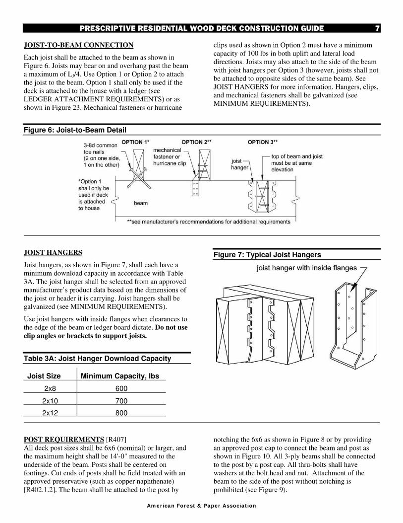
JOIST-TO-BEAM CONNECTION
Each joist shall be attached to the beam as shown in
Figure 6. Joists may bear on and overhang past the beam
a maximum of LJ/4. Use Option 1 or Option 2 to attach
the joist to the beam. Option 1 shall only be used if the
deck is attached to the house with a ledger (see
LEDGER ATTACHMENT REQUIREMENTS) or as
shown in Figure 23. Mechanical fasteners or hurricane
clips used as shown in Option 2 must have a minimum
capacity of 100 lbs in both uplift and lateral load
directions. Joists may also attach to the side of the beam
with joist hangers per Option 3 (however, joists shall not
be attached to opposite sides of the same beam). See
JOIST HANGERS for more information. Hangers, clips,
and mechanical fasteners shall be galvanized (see
MINIMUM REQUIREMENTS).
Figure 6: Joist-to-Beam Detail
JOIST HANGERS
Joist hangers, as shown in Figure 7, shall each have a
minimum download capacity in accordance with Table
3A. The joist hanger shall be selected from an approved
manufacturer’s product data based on the dimensions of
the joist or header it is carrying. Joist hangers shall be
galvanized (see MINIMUM REQUIREMENTS).
Use joist hangers with inside flanges when clearances to
the edge of the beam or ledger board dictate. Do not use
clip angles or brackets to support joists.
Table 3A: Joist Hanger Download Capacity
Joist Size Minimum Capacity, lbs
2x8 600
2x10 700
2x12 800
Figure 7: Typical Joist Hangers
POST REQUIREMENTS [R407]
All deck post sizes shall be 6x6 (nominal) or larger, and
the maximum height shall be 14'-0" measured to the
underside of the beam. Posts shall be centered on
footings. Cut ends of posts shall be field treated with an
approved preservative (such as copper naphthenate)
[R402.1.2]. The beam shall be attached to the post by
notching the 6x6 as shown in Figure 8 or by providing
an approved post cap to connect the beam and post as
shown in Figure 10. All 3-ply beams shall be connected
to the post by a post cap. All thru-bolts shall have
washers at the bolt head and nut. Attachment of the
beam to the side of the post without notching is
prohibited (see Figure 9).

8 PRESCRIPTIVE RESIDENTIAL WOOD DECK CONSTRUCTION GUIDE
Am er ican W ood Council
Figure 8: Post-to-Beam Attachment Requirements
Figure 9: Prohibited Post-to-Beam Attachment Condition
RIM JOIST REQUIREMENTS
Attach a continuous rim joist to the ends of joists as
shown in Figure 11. Attach decking to the rim joist as
shown in Figure 11. For more decking attachment
requirements, see DECKING REQUIREMENTS.
Figure 10: Alternate Approved Post-to-Beam Post Cap Attachment
Figure 11: Rim Joist Connection Details

PRESCRIPTIVE RESIDENTIAL WOOD DECK CONSTRUCTION GUIDE 9
Am er ican Forest & Paper Associa t ion
FOOTINGS [R403]
See Figure 12 and Table 4 for footing size, footing
thickness, and post attachment options and requirements.
All footings shall bear on solid ground and shall be
placed at least 12 inches below the undisturbed ground
surface or below the frost line, whichever is deeper;
bearing conditions shall be verified in the field by the
building official prior to placement of concrete. Where
the building official determines that in-place soils with
an allowable bearing capacity of less than 1,500 psf are
likely to be present at the site, the allowable bearing
capacity shall be determined by a soils investigation.
DECK FOOTINGS CLOSER THAN 5'-0" TO AN
EXISTING EXTERIOR HOUSE WALL MUST BEAR
AT THE SAME ELEVATION AS THE FOOTING OF
THE EXISTING HOUSE FOUNDATION.
Do not construct footings over utility lines or
enclosed meters. Call the local utilities before
digging.
Pre-manufactured post anchors shall be galvanized. See
MINIMUM REQUIREMENTS.
Table 4. Footing Sizes2
Beam
Span, LB
Joist
Span, LJ
Round1 Footing
Diameter
Footing
Thickness3
<10' 15" 6"
<14' 17" 6"
6'
<18' 20" 7"
<10' 17" 6"
<14' 20" 8"
8'
<18' 23" 9"
<10' 19" 7"
<14' 22" 9"
10'
<18' 25" 10"
<10' 21" 8"
<14' 24" 10"
12'
<18' 28" 11"
<10' 22" 9"
<14' 26" 11" 14'
<18' 30" 12"
<10' 24" 9"
<14' 28" 12"
16'
<18' 32" 13"
<10' 25" 10"
<14' 30" 12"
18'
<18' 34" 14" 1. Square footings are permitted to have widths 2" less
than the given diameter of round footings. 2. Assumes 1,500 psf soil bearing capacity. 3. Assumes 2,500 psi compressive strength of concrete.
Coordinate footing thickness with post base and anchor requirements.
Figure 12: Typical Footing Options

10 PRESCRIPTIVE RESIDENTIAL WOOD DECK CONSTRUCTION GUIDE
Am er ican W ood Council
LEDGER ATTACHMENT REQUIREMENTS
[R502.2.1]
GENERAL: Attach the ledger board, which shall be
equal to or greater than the deck joist depth, but less than
or equal to the rim joist depth, to the existing exterior
wall in accordance with Figure 14 through Figure 16.
When attachments are made to the existing house band
joist, the band joist shall be capable of supporting the
new deck. If this cannot be verified or conditions at the
existing house differ from the details herein, then either
a free-standing deck or full plan submission is required.
See FREE-STANDING DECKS.
SIDING AND FLASHING: House siding, or the
exterior finish system, must be removed prior to
installation of the ledger board. Approved corrosion
resistant flashing is required at any ledger board
connection to a wall of wood framed construction (see
MINIMUM REQUIREMENTS). See Figure 14 for
continuous flashing with drip edge. The threshold shall
be carefully flashed and caulked to prevent water
intrusion due to splash from the deck or melting snow
and ice.
MANUFACTURED WOOD I-JOIST: The term “I-
Joist” denotes manufactured wood “I” joists (see Figure
13A). Many new homes constructed with wood I-joists
include 1" or thicker engineered wood products (EWP) –
such as oriented strand board (OSB) or structural
composite lumber (SCL) including laminated veneer
lumber (LVL) – as band joists (or rim boards) that can
support the attachment of a deck (see Figure 14).
However, some older homes might be constructed with
band boards that are too thin (less than 1") to support a
deck. In such cases, a free-standing deck or a full plan
submission is required.
MANUFACTURED WOOD TRUSS: A metal plate
connected wood truss (MPCWT) is an engineered,
prefabricated structural component designed for each
specific application. MPCWT’s used in residential floors
are often installed with a 2x4 lumber “ribbon” at the
ends of the trusses (see Figure 13B), the purpose of
which is to tie the ends of the trusses together. The
ribbon board, by itself, is not intended to support the
deck ledger and deck. Installing residential decks when
the floor system for the house uses MPCWT requires a
standard detail provided by the truss designer, a free-
standing deck, or a full plan submission. Refer to the
WTCA Technical Note – Attachment of Residential
Decks to Wood Truss Floor Systems for special blocking
details and attachment requirements
(www.sbcindustry.com).
Figure 13A: Wood I-Joist Profile
Figure 13B: Metal Plate Connected (MPC) Wood Floor Trusses with a 2x4 Lumber “Ribbon” at the Ends of the Trusses

PRESCRIPTIVE RESIDENTIAL WOOD DECK CONSTRUCTION GUIDE 11
Am er ican Forest & Paper Associa t ion
Figure 14: General Attachment of Ledger Board to Band Joist or Rim Board
Figure 15: Attachment of Ledger Board to Foundation Wall (Concrete or Solid Masonry)
Figure 16: Attachment of Ledger Board to Foundation Wall (Hollow Masonry)

12 PRESCRIPTIVE RESIDENTIAL WOOD DECK CONSTRUCTION GUIDE
Am er ican W ood Council
PROHIBITED LEDGER ATTACHMENTS
Attachments to exterior veneers (brick, masonry, stone)
and to cantilevered floor overhangs or bay windows are
prohibited (see Figures 17 and 18). In such cases the
Figure 17: No Attachment to or Through Exterior Veneers (Brick, Masonry, Stone)
deck shall be free-standing (see FREE-STANDING
DECKS).
Figure 18: No Attachment to House Overhang
LEDGER BOARD FASTENERS
Deck ledger connection to band joist or rim board.
The connection between a deck ledger and a 2-inch
nominal lumber band joist (1-½" actual) or EWP rim
board bearing on a sill plate or wall plate shall be
constructed with ½" lag screws or bolts with washers per
Table 5 and Figure 19 (see MINIMUM
REQUIREMENTS). Only those fasteners noted below
are permitted. LEAD ANCHORS ARE PROHIBITED.
Table 5. Fastener Spacing for a Southern Pine, Douglas Fir-Larch, or Hem-Fir Deck Ledger and a 2-inch Nominal Solid-Sawn Spruce-Pine-Fir7,9 Band Joist or EWP Rim Board6 (Deck Live Load = 40 psf, Deck Dead Load = 10 psf)
3,6
Joist Span Rim Board
or Band Joist
6'-0" and less
6'-1" to
8'-0"
8'-1" to
10'-0"
10'-1" to
12'-0"
12'-1" to
14'-0"
14'-1" to
16'-0"
16'-1" to
18'-0"
Connection Details On-Center Spacing of Fasteners4,5
½" diameter lag screw with 15
/32" maximum sheathing1
1" EWP6
1-1/8" EWP
6
1-½" Lumber7,9
24" 28" 30"
18" 21" 23"
14" 16" 18"
12" 14" 15"
10" 12" 13"
9" 10" 11"
8" 9"
10"
½" diameter bolt with 15
/32" maximum sheathing
1" EWP6
1-1/8" EWP
6
1-½" Lumber7,9
24" 28" 36"
18" 21" 36"
14" 16" 34"
12" 14" 29"
10" 12" 24"
9" 10" 21"
8" 9"
19"
½" diameter bolt with 15
/32" maximum sheathing and ½" stacked washers
2,8
1" EWP6
1-1/8" EWP
6
1-½" Lumber7,9
24" 28" 36"
18" 21" 36"
14" 16" 29"
12" 14" 24"
10" 12" 21"
9" 10" 18"
8" 9"
16" 1 The t ip of the lag screw shall fully extend beyond the inside face of the band joist . 2 The m axim um gap between the face of the ledger board and face of the wall sheathing shall be ½". 3 Ledgers shall be flashed or caulked to prevent water from contact ing the house band joist ( see Figures 14, 15, and 16) . 4 Lag screws and bolts shall be staggered per Figure 19. 5 Deck ledgers shall be m inimum 2x8 pressure-preservat ive- t reated No.2 grade lum ber, or other approved m aterials as established
by standard engineering pract ice. 6 When solid-sawn pressure-preservat ive- t reated deck ledgers are at tached to engineered wood products (m inim um 1" thick wood
st ructural panel band joist or st ructural com posite lum ber including lam inated veneer lumber) , the ledger at tachment shall be designed in accordance with accepted engineering pract ice. Tabulated values based on 300 lbs and 350 lbs for 1" and 1- 1/ 8" EWP r im board, respect ively.
7 A m inim um 1"x9½" Douglas fir- larch lam inated veneer lum ber r im board shall be perm it ted in lieu of the 2" nom inal band joist . 8 Wood st ructural panel sheathing, gypsum board sheathing, or foam sheathing not exceeding one inch thickness shall be perm it ted.
The m axim um distance between the face of the ledger board and the face of the band joist shall be one inch. 9 Fastener spacing also applies to southern pine, Douglas f ir - larch, and hem - fir band joists.

PRESCRIPTIVE RESIDENTIAL WOOD DECK CONSTRUCTION GUIDE 13
Am er ican Forest & Paper Associa t ion
Placement of lag screws or bolts in deck ledgers
The lag screws or bolts shall be placed two inches from
the bottom or top of the deck ledgers and between two
and five inches from the ends. The lag screws or bolts
shall be staggered from the top to the bottom along the
horizontal run of the deck ledger (see Figure 19). Proper
installation of lag screws or bolts shall be verified by the
building official.
Figure 19: Ledger Board Fastener Spacing and Clearances
Thru-Bolts
Thru-bolts shall have a diameter of ½". Pilot holes for
thru-bolts shall be 17
/32" to 9/16" in diameter. Thru-bolts
require washers at the bolt head and nut.
Expansion and Adhesive Anchors
Use approved expansion or adhesive anchors when
attaching a ledger board to a concrete or solid masonry
wall as shown in Figure 15 or a hollow masonry wall
with a grouted cell as shown in Figure 16. Expansion
and adhesive anchor bolts shall have a diameter of ½".
Minimum embedment length shall be per the
manufacturer’s recommendations. All anchors must have
washers.
Lag Screws
Lag screws shall have a diameter of ½" (see MINIMUM
REQUIREMENTS). Lag screws may be used only when
the field conditions conform to those shown in Figure
14. See Figure 20 for lag screw length and shank
requirements. All lag screws shall be installed with
washers.
Figure 20: Lag Screw Requirements
Lag screw installation requirements: Each lag screw
shall have pilot holes drilled as follows: 1) Drill a ½"
diameter hole in the ledger board, 2) Drill a 5/16"
diameter hole into the band board of the existing house.
DO NOT DRILL A ½" DIAMETER HOLE INTO THE
BAND BOARD.
The threaded portion of the lag screw shall be inserted
into the pilot hole by turning. DO NOT DRIVE LAG
SCREWS WITH A HAMMER. Use soap or a wood-
compatible lubricant as required to facilitate tightening.
Each lag screw shall be thoroughly tightened (snug but
not over-tightened to avoid wood damage).

14 PRESCRIPTIVE RESIDENTIAL WOOD DECK CONSTRUCTION GUIDE
Am er ican W ood Council
FREE-STANDING DECKS
Decks which are free-standing do not utilize the exterior
wall of the existing house to support vertical loads (see
Figure 21); instead, an additional beam with posts is
provided at or within L/4 of the existing house. THE
ASSOCIATED DECK POST FOOTINGS SHALL BE
PLACED AT THE SAME ELEVATION AS THE
EXISTING HOUSE FOOTING (see Figure 2 and Figure
12). For houses with basements, a cylindrical footing
(caisson) is recommended to minimize required
excavation at the basement wall. Beam size is
determined by Table 3.
Figure 21: Free-Standing Deck
DECK STABILITY
Decks greater than 2 feet above grade shall be provided
with diagonal bracing.
Figure 22: Diagonal Bracing Requirements

PRESCRIPTIVE RESIDENTIAL WOOD DECK CONSTRUCTION GUIDE 15
Am er ican Forest & Paper Associa t ion
Diagonal Bracing: Provide diagonal bracing both
parallel and perpendicular to the beam at each post as
shown in Figure 22. When parallel to the beam, the
bracing shall be bolted to the post at one end and beam
at the other. When perpendicular to the beam, the
bracing shall be bolted to the post at one end and a joist
or blocking between joists at the other. When a joist
does not align with the bracing location, provide
blocking between the next adjacent joists. Decks
attached to the house do not require diagonal bracing
perpendicular to the house.
Attachment to House: Attach the deck rim joist to the
existing house exterior wall as shown in Figure 23 for a
free-standing deck or attach the deck ledger to the house
as shown in Figures 14, 15, or 16. The wall must be
sheathed with minimum 3/8" wood structural panel
sheathing. Use lag screws or thru-bolts when fastening
to an existing band joist or wall stud; use expansion
anchors or epoxy anchors when fastening to concrete or
masonry. DO NOT ATTACH TO BRICK VENEERS.
VERIFY THIS CONDITION IN THE FIELD PRIOR
TO UTILIZING THIS METHOD. Fasteners shall be 16"
on center and staggered in 2 rows for free-standing
decks. Flashing over the rim joist is required and must
be installed in accordance with the flashing provisions in
the LEDGER ATTACHMENT REQUIREMENTS.
Figure 23: Attachment of Free-Standing Deck to House for Deck Stability
GUARD REQUIREMENTS
All decks greater than 30" above grade are required to
have a guard [R312.1] - one example is shown in Figure
24. Other methods and materials may be used for guard
construction when approved by the authority having
jurisdiction.
Figure 24: Example Guard Detail

16 PRESCRIPTIVE RESIDENTIAL WOOD DECK CONSTRUCTION GUIDE
Am er ican W ood Council
GUARD POST ATTACHMENTS
Deck guard posts shall be a minimum 4x4 (nominal)
No.2 or higher grade (for species listed in Table 1) with
an adjusted bending design value not less than 1,050 psi.
GUARD POST TO OUTSIDE JOIST: Guard posts
for guards which run parallel to the deck joists shall be
attached to the outside joist per Figure 25.
Figure 25: Guard Post to Outside Joist Example
GUARD POST TO RIM JOIST: Guard posts for
guards that run perpendicular to the deck joists shall be
attached to the rim joist in accordance with Figure 26.
As shown in Figure 26, hold-down anchors must be
installed to attach the guard post and rim joist to the
deck joists. There shall be a minimum of two ½"
diameter bolts at the hold-down anchors' attachment to
the joist. Only hold-down anchor models meeting these
minimum requirements shall be used.
Figure 26: Guard Post to Rim Joist Example

PRESCRIPTIVE RESIDENTIAL WOOD DECK CONSTRUCTION GUIDE 17
Am er ican Forest & Paper Associa t ion
STAIR REQUIREMENTS
Stairs, stair stringers, and stair guards shall meet the
requirements shown in Figure 27 through Figure 34 and
Table 6 except where amended by the local jurisdiction.
All stringers shall be a minimum of 2x12. Stair stringers
shall not span more than the dimensions shown in Figure
28. If the stringer span exceeds these dimensions, then a
4x4 post may be provided to support the stringer and
shorten its span length. The 4x4 post shall be notched
and bolted to the stringer with (2) ½" diameter through-
bolts with washers per Figure 8. The post shall be
centered on a 12" diameter or 10" square, 6" thick
footing. The footing shall be constructed as shown in
Figure 34 and attached to the post as shown in Figure 12.
An intermediate landing may also be provided to shorten
the stringer span (see provisions below). If the total
vertical height of a stairway exceeds 12'-0", then an
intermediate landing shall be required. All intermediate
stair landings must be designed and constructed as a
free-standing deck using the details in this document.
Stairs shall be a minimum of 36" in width as shown in
Figure 33 [R311.5]. If only cut stringers are used, a
minimum of three are required. For stairs greater than
36" in width, a combination of cut and solid stringers
can be used, but shall be placed at a maximum spacing
of 18" on center (see Figure 29). The width of each
landing shall not be less than the width of the stairway
served. Every landing shall have a minimum dimension
of 36" measured in the direction of travel and no less
than the width of the stairway served [R311.5].
Figure 27: Tread and Riser Detail
Figure 28: Stair Stringer Requirements
Figure 29: Tread Connection Requirements
Table 6: Minimum Tread Size for Cut and Solid Stringers1
Species Cut
Stringer Solid
Stringer
Southern Pine 2x4 or 5/4 2x6
Douglas Fir Larch, Hem-Fir, SPF
2 2x4 or 5/4 2x8 or 3x4
Redwood, Western Cedars, Ponderosa Pine
3, Red Pine
3 2x4 or 5/4 2x10 or 3x4
1. Assumes 300 lb concentrated load, L/288 deflection limit, No. 2 grade, and wet service conditions.
2. Incising assumed for refractory species including Douglas fir-larch, hem-fir, and spruce-pine-fir.
3. Design values based on northern species with no incising assumed.

18 PRESCRIPTIVE RESIDENTIAL WOOD DECK CONSTRUCTION GUIDE
Am er ican W ood Council
Figure 30: Stair Guard Requirements
Figure 31: Stair Stringer Attachment Detail
STAIR HANDRAIL REQUIREMENTS
All stairs with 4 or more risers shall have a handrail on
at least one side (see Figure 32A) [R311.5.6]. The
handrail height measured vertically from the sloped
plane adjoining the tread nosing shall be not less than 34
inches and not more than 38 inches (see Figure 30)
[R311.5.6.1]. Handrails shall be graspable and shall be
composed of decay-resistant and/or corrosion resistant
material. Handrails shall be Type I, Type II, or provide
equivalent graspability (see Figure 32B). Type I shall
have a perimeter dimension of at least 4" and not greater
than 6-¼". Type II rails with a perimeter greater than
6-¼" shall provide a graspable finger recess area on both
sides of the profile [R311.5.6.3]. All shapes shall have a
smooth surface with no sharp corners. Handrails shall
run continuously from a point directly over the lowest
riser to a point directly over the highest riser and shall
return to the guard at each end (see Figure 33). Handrails
may be interrupted by guard posts at a turn in the stair
[R311.5.6.2].
Figure 32A: Handrail Mounting Examples
Figure 32B: Handrail Grip Size

PRESCRIPTIVE RESIDENTIAL WOOD DECK CONSTRUCTION GUIDE 19
Am er ican Forest & Paper Associa t ion
STAIR FOOTING REQUIREMENTS [R403]
Where the stairway meets grade, attach the stringers to
the stair guard posts as shown in Figure 34. Posts shall
bear on footings. All footings shall bear on solid ground
and shall be placed at least 12 inches below the
undisturbed ground surface or below the frost line,
whichever is deeper (see Figure 34). Stringers shall not
bear on new or existing concrete pads or patios that are
not founded below this depth. When guards are not
required (see GUARD REQUIREMENTS), posts may
terminate below the bottom tread elevation.
STAIR LIGHTING REQUIREMENTS [R303.6]
Stairways shall have a light source located at the top
landing such that all stairs and landings are illuminated.
The light switch shall be operated from inside the house.
However, motion detected or timed switches are
acceptable.
Figure 33: Miscellaneous Stair Requirements
Figure 34: Stair Footing Detail
FRAMING AT CHIMNEY OR BAY WINDOW
All members at a chimney or bay window shall be
framed in accordance with Figure 35. Headers may span
a maximum of 6'-0". When a chimney or bay window is
wider than 6'-0", one or more 6x6 posts may be added to
reduce header spans to less than 6'-0". In such cases, the
post footing must meet the requirements in the
FOOTINGS section. Headers with a span length greater
than 6'-0" require a plan submission.
Figure 35: Detail for Framing Around a Chimney or Bay Window

20 PRESCRIPTIVE RESIDENTIAL WOOD DECK CONSTRUCTION GUIDE
Am er ican W ood Council
It is intended that this document be used in conjunction with competent design, accurate fabrication, and adequate supervision of construction. While every effort has been made to insure the accuracy of the information presented, the American Forest & Paper Association and its members do not assume responsibility for errors or omissions in the document, nor for designs, plans, or construction prepared from it. Those using this document assume all liability arising from its use.
Copyright © 2007, 2008
American Forest & Paper Association, Inc. 05-08

![epssweden.comepssweden.com/files/Stop [VENS] and Regulating Valves [VENR] acc.pdf · asme/ansi b16.10 asme-ansi b16.5 asme-ansi b16.10 asme/ansi b16.25 ... 14 43 85 128 48 96 144](https://img.pdfslide.net/doc/110x75/5a9ff4687f8b9a8e178d6630/vens-and-regulating-valves-venr-accpdfasmeansi-b1610-asme-ansi-b165-asme-ansi.jpg)


![INDEX [assets.tequipment.net] · INDEX 491 A Abbreviations, ... ANSI B94.25 391 ANSI keyseat dimensions 262 ... ANSI/ASME B1.13M-1983 280, 396 ANSI/ASME B18.3 314](https://img.pdfslide.net/doc/110x75/5b6991367f8b9a68538e3fe0/index-index-491-a-abbreviations-ansi-b9425-391-ansi-keyseat-dimensions.jpg)